SlideShare a Scribd company logo
Schema Integration, View Integration and Database Integration, ER
Model & Diagrams and Object-Oriented Model
Mobarok Hossen 17-90216-2, Abdulla Al Mamun 17-90217-2
Rajib Chowdhury 17-90189-2, D.M. Anisuzzaman 17-90119-2
February 27, 2018
1 ER Model & Diagram
An entity relationship model, also called an entity-
relationship (ER) diagram, is a graphical repre-
sentation of entities (which will become your ta-
bles) and their relationships to each other. ER
Diagrams are most often used to design or de-
bug relational databases in the fields of software
engineering, business information systems, educa-
tion and research. Also known as ERDs or ER
Models, they use a defined set of symbols such as
rectangles, diamonds, ovals and connecting lines
to depict the interconnectedness of entities, rela-
tionships and their attributes.
ER diagrams are related to data structure di-
agrams (DSDs), which focus on the relationships
of elements within entities instead of relationships
between entities themselves. ER diagrams also are
often used in conjunction with data flow diagrams
(DFDs), which map out the flow of information for
processes or systems.
Entity: Entity, which are represented by rect-
angles. An entity is an object or concept about
which you want to store information.
Weak Entity: A weak entity is an entity that de-
pends on the existence of another entity.
Fig. 1: Entity Fig. 2: Weak Entity
Attributes: Attributes, which are represented
by ovals. A key attribute is the unique, distin-
guishing characteristic of the entity. An entity can
have as many attributes as necessary. There are
some attribute type such as:
Primary Key: It’s sketched the same as a normal
attribute but with underline.
Fig. 3: Attribute
Fig. 4: Primary key
Attr.
Composite Attribute: It’s a value that com-
posed of some other values. For example, you may
have Address that’s composed of street, city and
number
Fig. 5: Composite Attribute
Multivalued Attribute: If an attribute can have
more than one value it is called a multi valued
attribute. For example, a teacher entity can have
multiple subject values.
Derived Attribute: When you have a column
where it’s value could be calculated from another
column. This is found rarely in ER diagrams
Fig. 6: Multivalued
Attribute
Fig. 7: Derived At-
tribute
Actions: Actions which are represented by di-
amond shapes, show how two entities share infor-
mation in the database using their relationship.
Fig. 8: Relationship/Action
There are so many Entity Relationship Diagram
Style:
1. Information Engineering Style
2. Chen Style
3. Bachman Style
4. Martin Style
1
Fig. 9: Information Engineering Style Fig. 10: Chen Style
Fig. 11: Bachman Style Fig. 12: Martin Style
Fig. 13: ER Model & Diagram
2
How to Draw ER Diagrams?
Below points show how to go about creating
an ER diagram: Identify all the entities. Cre-
ate rectangles for all entities and name them
properly. Identify relationships between entities
Connect them using a line and add a diamond
in the middle describing the relationship. Add
attributes for entities. Give meaningful at-
tribute names so they can be understood easily.
Benefits of ER diagrams: ER diagrams con-
stitute a very useful framework for creating and
manipulating databases. ER diagrams are easy to
understand. ER diagrams to easily communicate
with developers, customers, and end users, regard-
less of their IT proficiency ER diagrams are read-
ily translatable into relational tables which can be
used to quickly build databases ER diagrams may
be applied in other contexts such as describing the
different relationships and operations within an or-
ganization.
2 Object Oriented Database
Model
OODMS: Database that stores data elements
as objects. Uses object-oriented concepts. Object
- like an entity in an E-R Diagram.
Fig. 14: Object based ER Model
Why use OODMS: Complex data or rela-
tionship requirements. Lack of unique, natural
identification. Large numbers of many to many
relationships. Frequent use of type codes such as
those found in the relational schema.
Typical Applications for OODMS:
Computer-aided design (CAD). Computer-
aided software engineering (CASE). Multimedia
databases: Images, video, games, etc. Office
automation systems (OIS). Expert database
systems.
Object Oriented Concept: Vari-
ables/Attributes – Object Data. Relationships –
References to other objects. Methods – Object
Functions. Messages – Accessing Methods
Fig. 15: Object based ER Model
Advantages of OODMS: Designer can
specify the structure of objects and their behavior
(methods). Better interaction with object-
oriented languages such as Java and C++. Defi-
nition of complex and user-defined types. Encap-
sulation of operations and user-defined methods.
Disadvantages of OODMS: Still develop-
ing: Lack of accepted standards, Lack of de-
velopment tools,Change is more likely to occur
in model. More complicated than the relational
model. Takes longer to learn. Not as efficient when
data and relations are simple.
3 Schema Integration
Database Schema: Overall description of the
database which is represented by diagrammat-
ically, visually, graphically is called database
schema. It is also defined by a relation of the
database.
Instance: Collection of information stored in
the database at a particular moment of time is
called database instance which keeps on changing
by insertion, deletion or updating. Every differ-
ent instance, there can be a different state of the
database.
Sub-Schema: It is the lower level or the sub level
of the schema which actually corresponds to an
application where programmers or users view of
the data item types and record types, which they
use.
Schema Integration: Schema integration is
the activity of integrating the schemas of exist-
ing or proposed databases into a global, unified
schema. It actually merges the schemas into a sin-
gle global schema where fundamental problems are
to take two or more database schemas and also to
produce a mapping between attributes of the two
or more schemas
Fig. 16: Integrated schema and mappings
Fig. 17: Integrated schema with ER Model3
Framework for Schema Integration:
1) Local Schemas: Existing and proposed
schemas of the database are taken as local schemas
for producing a global unified schema.
2) Schema Transformation: In this part, n
source local schemas act as input and which are
transformed into n source homogenized schemas
by using the method of model and Design Homog-
enization.
a. Data Model Homogenization: Here all data
sources are described using the same model.
b. Design Homogenization: Enforce standard
design rules to reduce the number of structural
conflicts.
3) Schema Matching: Relies on information
such as name, description, data type, relationship
type, constraints etc.
Match Cardinality: a. 1:1 match: one element
in one schema matches one element of another
schema.
b. 1: m match: one element in one schema
matches m elements of another schema.
c. m :n match: m elements in one schema
matches n elements of another schema.
Fig. 18: Framework for Schema Integration
4) Schema Integration: Merge the schemas into
a single global schema using different integration
strategy which’s are:
i. One shot strategy: It is an efficient integra-
tion process where many correspondences between
concepts have to be considered together.
ii. Pair at a time strategy: It is more efficient
integration process which gives priority to most
relevant and stable schemas.
iii. Balanced strategy: It will be preferred when
the cohesion among schemas is high (e.g.: Produc-
tion, marketing, sales).
Fig. 19: (a) One shot strategy, (b) Pair at a time
strategy, (c) Balanced strategy
4 View Integration
We have to wait a little bit to go to the topic
of view integration. Let’s see where the concept
of view integration fit in the database system de-
velopment process (DSDP). DSDP can be divided
into four steps: requirements analysis; conceptual
design; logical design and physical design. The
step ‘conceptual design’ is divided into two steps:
view modeling and modification and view integra-
tion. And here comes the concept of view integra-
tion.
In view integration step individual database in-
tegrated into a global database schema. There
are two view integration approaches: syntac-
tic approach and semantic approach. Syntactic
approach employs functional relationships (func-
tional dependencies) among attributes in different
database views to perform view integration. Se-
mantic approach uses the meaning of the elements
in database views to perform view integration. Se-
mantic approach uses the meaning of the elements
in database views to perform view integration.
View integration is not as easy as it sounds. It
arises some conflict when we try to integrate differ-
ent view. There are mainly two types of conflicts:
naming conflict and structural conflict. Table 1
shows the brief description of these conflicts. Nam-
ing conflict contains: Homonyms and Synonyms
and the rest four are structural conflict.
Table 1: Conflicts in View Integration
Conflict Name Meaning Example
Homonyms Same name for elements
representing different real
world objects in different
database views.
4
Conflict Name Meaning Example
Synonyms Elements representing
the same real world
object; described by dif-
ferent names in different
database views.
Type Conflicts The same real world
object is represented
by different modeling
constructs in different
database views.
Key Conflicts Different keys are assigned
to entities or relationships
representing the same real
world object in different
database views..
Cardinalities
Conflicts
The min-card or max-
card within an entity-
relationship association
are incompatible in
different database views.
Semantic Con-
flicts
Different semantic inter-
pretations are abstracted
into different database
views.
When a conflict is found between two
database views, a solution has to be found.
All case solutions are combinations of a
set of 11 elementary solution operations:
1. A relationship becomes an entity
2. A relationship attribute becomes an entity
3. An entity attribute becomes an E-R construct
4. Association of an entity to a relationship
5. Relocation of a relationship after creation of
new superset or subset classes.
6. Representation of containment.
7. Representation of a common role (W- relation-
ship).
8. Representation of a common superset without
overlap
9. Representation of a common superset with over-
lap
10. Renaming of homonyms and synonyms.
11. Addition of missing objects.
5 Database Integration
Database Integration involves combining data
from several disparate sources, which are stored
using various technologies and provide a unified
view of the data. In simple terms, sharing infor-
mation between two different computer systems is
database integration.
Fig. 20:
5
Three types of database integration:
1) Physical: Coping the data to warehouse.
2) Virtual: Keep the data only at the sources.
3) Within a single organization: Integrating data from different departments or sectors.
The core problem associated with database integration is heterogeneity among the data sources. There exist 6
types of heterogeneity. Table 2 gives a brief description of these 6 types.
Table 2: Heterogeneities in Database Integration
Heterogeneity
Name
Meaning Example
Source Type The source’s system of storing
data can be different.
Communication 1) Some systems have web inter-
face others do not. 2) Some sys-
tems allow direct query language
others offer APIs.
Schema The source’s structure of the ta-
bles storing the data can be dif-
ferent (even if storing the same
data).
Data Type Storing the same data (and val-
ues) but with different data
types.
Value Same logical values stored in dif-
ferent ways.
Semantic Same values in different sources
can mean different things.
6
Three models (Federated Databases; Data Warehousing and Mediation) of database integration are described
briefly below:
Table 3: Heterogeneities in Database Integration
Name Meaning Example
Federated
Databases
It contains the simplest architecture. Every
pair of sources can build their own mapping
and transformation.
Advantage: If many sources and only very
few are communicating.
Disadvantages: 1) If most sources are com-
municating (n2 mappings) and 2) If sources
are dynamic (need to change many mappings).
Data Warehous-
ing
It is a very common approach. Data from mul-
tiple sources are copied and stored in a ware-
house. Data is materialized in the warehouse.
Users can then query the warehouse database
only.
Mediation Mediator is a virtual view over the data (it
does not store any data). Data is stored only
at the sources. Mediator has a virtual schema
that combines all schemas from the sources.
The mapping takes place at query time. This
is unlike warehousing where mapping takes
place at upload time.
7

More Related Content

PPTX
Object Oriented Testing
PPTX
Patterns
PPTX
Presentation on uml
PPTX
Threads (operating System)
PPT
Introduction to Rational Rose
PDF
Agile model
PDF
Algorithms Lecture 2: Analysis of Algorithms I
PPTX
Architectural Modeling
Object Oriented Testing
Patterns
Presentation on uml
Threads (operating System)
Introduction to Rational Rose
Agile model
Algorithms Lecture 2: Analysis of Algorithms I
Architectural Modeling

What's hot (20)

PPT
Use case Diagram
DOCX
Processes and threads
PPT
UML Diagrams
PPTX
Control Structure in JavaScript (1).pptx
PDF
State chart diagram
PPTX
Link and association in Java
PPT
10 component diagram
PPT
Client-Server Computing
PPTX
Organized and disorganized complexity
PPTX
object oriented methodologies
PPTX
System testing
PDF
Thread
PPTX
Sequence diagram
PPT
Software design, software engineering
PPTX
Predicate logic
PPT
Object and class relationships
PPTX
Language and Processors for Requirements Specification
PPT
Lecture04- Use Case Diagrams
Use case Diagram
Processes and threads
UML Diagrams
Control Structure in JavaScript (1).pptx
State chart diagram
Link and association in Java
10 component diagram
Client-Server Computing
Organized and disorganized complexity
object oriented methodologies
System testing
Thread
Sequence diagram
Software design, software engineering
Predicate logic
Object and class relationships
Language and Processors for Requirements Specification
Lecture04- Use Case Diagrams
Ad

Similar to Schema Integration, View Integration and Database Integration, ER Model & Diagrams and Object-Oriented Model (20)

PDF
chapter 2-DATABASE SYSTEM CONCEPTS AND architecture [Autosaved].pdf
PPTX
Unit-1-DBMS-SUN-4 everything you need to know.pptx
DOCX
Student POST  Database processing models showcase the logical s.docx
DOCX
Data Modeling.docx
PPT
Week 4 The Relational Data Model & The Entity Relationship Data Model
PDF
Data Warehouse Designing: Dimensional Modelling and E-R Modelling
PDF
Mapping object to_data_models_with_the_uml
PDF
Database Concepts & SQL(1).pdf
PPT
software_engg-chap-03.ppt
PPTX
DBMS-2.pptx
PPTX
Database System Concepts AND architecture [Autosaved].pptx
PDF
2. Chapter Two.pdf
PPTX
Data models
DOCX
Data models
DOCX
Data models
DOCX
Database
DOC
DATA BASE MANAGEMENT SYSTEM - SHORT NOTES
PPTX
Database Management System(UNIT 1)
PPTX
Database Management System(UNIT 1)
PPTX
Data resource management
chapter 2-DATABASE SYSTEM CONCEPTS AND architecture [Autosaved].pdf
Unit-1-DBMS-SUN-4 everything you need to know.pptx
Student POST  Database processing models showcase the logical s.docx
Data Modeling.docx
Week 4 The Relational Data Model & The Entity Relationship Data Model
Data Warehouse Designing: Dimensional Modelling and E-R Modelling
Mapping object to_data_models_with_the_uml
Database Concepts & SQL(1).pdf
software_engg-chap-03.ppt
DBMS-2.pptx
Database System Concepts AND architecture [Autosaved].pptx
2. Chapter Two.pdf
Data models
Data models
Data models
Database
DATA BASE MANAGEMENT SYSTEM - SHORT NOTES
Database Management System(UNIT 1)
Data resource management
Ad

Recently uploaded (20)

PDF
Diabetes mellitus diagnosis method based random forest with bat algorithm
PDF
Blue Purple Modern Animated Computer Science Presentation.pdf.pdf
PDF
cuic standard and advanced reporting.pdf
PPTX
Cloud computing and distributed systems.
PDF
Machine learning based COVID-19 study performance prediction
PDF
NewMind AI Weekly Chronicles - August'25 Week I
PDF
Encapsulation theory and applications.pdf
PPTX
Big Data Technologies - Introduction.pptx
PPTX
A Presentation on Artificial Intelligence
PDF
Dropbox Q2 2025 Financial Results & Investor Presentation
PDF
Architecting across the Boundaries of two Complex Domains - Healthcare & Tech...
PPT
Teaching material agriculture food technology
PPTX
Detection-First SIEM: Rule Types, Dashboards, and Threat-Informed Strategy
PDF
Shreyas Phanse Resume: Experienced Backend Engineer | Java • Spring Boot • Ka...
PPTX
Digital-Transformation-Roadmap-for-Companies.pptx
PPTX
VMware vSphere Foundation How to Sell Presentation-Ver1.4-2-14-2024.pptx
PDF
Network Security Unit 5.pdf for BCA BBA.
PPTX
Effective Security Operations Center (SOC) A Modern, Strategic, and Threat-In...
PDF
Agricultural_Statistics_at_a_Glance_2022_0.pdf
PDF
Advanced methodologies resolving dimensionality complications for autism neur...
Diabetes mellitus diagnosis method based random forest with bat algorithm
Blue Purple Modern Animated Computer Science Presentation.pdf.pdf
cuic standard and advanced reporting.pdf
Cloud computing and distributed systems.
Machine learning based COVID-19 study performance prediction
NewMind AI Weekly Chronicles - August'25 Week I
Encapsulation theory and applications.pdf
Big Data Technologies - Introduction.pptx
A Presentation on Artificial Intelligence
Dropbox Q2 2025 Financial Results & Investor Presentation
Architecting across the Boundaries of two Complex Domains - Healthcare & Tech...
Teaching material agriculture food technology
Detection-First SIEM: Rule Types, Dashboards, and Threat-Informed Strategy
Shreyas Phanse Resume: Experienced Backend Engineer | Java • Spring Boot • Ka...
Digital-Transformation-Roadmap-for-Companies.pptx
VMware vSphere Foundation How to Sell Presentation-Ver1.4-2-14-2024.pptx
Network Security Unit 5.pdf for BCA BBA.
Effective Security Operations Center (SOC) A Modern, Strategic, and Threat-In...
Agricultural_Statistics_at_a_Glance_2022_0.pdf
Advanced methodologies resolving dimensionality complications for autism neur...

Schema Integration, View Integration and Database Integration, ER Model & Diagrams and Object-Oriented Model

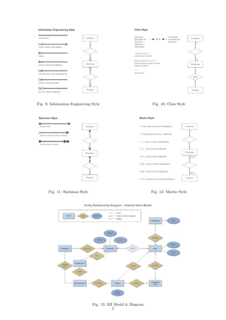
  • 1. Schema Integration, View Integration and Database Integration, ER Model & Diagrams and Object-Oriented Model Mobarok Hossen 17-90216-2, Abdulla Al Mamun 17-90217-2 Rajib Chowdhury 17-90189-2, D.M. Anisuzzaman 17-90119-2 February 27, 2018 1 ER Model & Diagram An entity relationship model, also called an entity- relationship (ER) diagram, is a graphical repre- sentation of entities (which will become your ta- bles) and their relationships to each other. ER Diagrams are most often used to design or de- bug relational databases in the fields of software engineering, business information systems, educa- tion and research. Also known as ERDs or ER Models, they use a defined set of symbols such as rectangles, diamonds, ovals and connecting lines to depict the interconnectedness of entities, rela- tionships and their attributes. ER diagrams are related to data structure di- agrams (DSDs), which focus on the relationships of elements within entities instead of relationships between entities themselves. ER diagrams also are often used in conjunction with data flow diagrams (DFDs), which map out the flow of information for processes or systems. Entity: Entity, which are represented by rect- angles. An entity is an object or concept about which you want to store information. Weak Entity: A weak entity is an entity that de- pends on the existence of another entity. Fig. 1: Entity Fig. 2: Weak Entity Attributes: Attributes, which are represented by ovals. A key attribute is the unique, distin- guishing characteristic of the entity. An entity can have as many attributes as necessary. There are some attribute type such as: Primary Key: It’s sketched the same as a normal attribute but with underline. Fig. 3: Attribute Fig. 4: Primary key Attr. Composite Attribute: It’s a value that com- posed of some other values. For example, you may have Address that’s composed of street, city and number Fig. 5: Composite Attribute Multivalued Attribute: If an attribute can have more than one value it is called a multi valued attribute. For example, a teacher entity can have multiple subject values. Derived Attribute: When you have a column where it’s value could be calculated from another column. This is found rarely in ER diagrams Fig. 6: Multivalued Attribute Fig. 7: Derived At- tribute Actions: Actions which are represented by di- amond shapes, show how two entities share infor- mation in the database using their relationship. Fig. 8: Relationship/Action There are so many Entity Relationship Diagram Style: 1. Information Engineering Style 2. Chen Style 3. Bachman Style 4. Martin Style 1
  • 2. Fig. 9: Information Engineering Style Fig. 10: Chen Style Fig. 11: Bachman Style Fig. 12: Martin Style Fig. 13: ER Model & Diagram 2
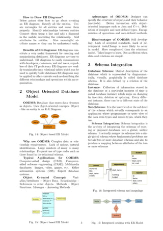
  • 3. How to Draw ER Diagrams? Below points show how to go about creating an ER diagram: Identify all the entities. Cre- ate rectangles for all entities and name them properly. Identify relationships between entities Connect them using a line and add a diamond in the middle describing the relationship. Add attributes for entities. Give meaningful at- tribute names so they can be understood easily. Benefits of ER diagrams: ER diagrams con- stitute a very useful framework for creating and manipulating databases. ER diagrams are easy to understand. ER diagrams to easily communicate with developers, customers, and end users, regard- less of their IT proficiency ER diagrams are read- ily translatable into relational tables which can be used to quickly build databases ER diagrams may be applied in other contexts such as describing the different relationships and operations within an or- ganization. 2 Object Oriented Database Model OODMS: Database that stores data elements as objects. Uses object-oriented concepts. Object - like an entity in an E-R Diagram. Fig. 14: Object based ER Model Why use OODMS: Complex data or rela- tionship requirements. Lack of unique, natural identification. Large numbers of many to many relationships. Frequent use of type codes such as those found in the relational schema. Typical Applications for OODMS: Computer-aided design (CAD). Computer- aided software engineering (CASE). Multimedia databases: Images, video, games, etc. Office automation systems (OIS). Expert database systems. Object Oriented Concept: Vari- ables/Attributes – Object Data. Relationships – References to other objects. Methods – Object Functions. Messages – Accessing Methods Fig. 15: Object based ER Model Advantages of OODMS: Designer can specify the structure of objects and their behavior (methods). Better interaction with object- oriented languages such as Java and C++. Defi- nition of complex and user-defined types. Encap- sulation of operations and user-defined methods. Disadvantages of OODMS: Still develop- ing: Lack of accepted standards, Lack of de- velopment tools,Change is more likely to occur in model. More complicated than the relational model. Takes longer to learn. Not as efficient when data and relations are simple. 3 Schema Integration Database Schema: Overall description of the database which is represented by diagrammat- ically, visually, graphically is called database schema. It is also defined by a relation of the database. Instance: Collection of information stored in the database at a particular moment of time is called database instance which keeps on changing by insertion, deletion or updating. Every differ- ent instance, there can be a different state of the database. Sub-Schema: It is the lower level or the sub level of the schema which actually corresponds to an application where programmers or users view of the data item types and record types, which they use. Schema Integration: Schema integration is the activity of integrating the schemas of exist- ing or proposed databases into a global, unified schema. It actually merges the schemas into a sin- gle global schema where fundamental problems are to take two or more database schemas and also to produce a mapping between attributes of the two or more schemas Fig. 16: Integrated schema and mappings Fig. 17: Integrated schema with ER Model3
  • 4. Framework for Schema Integration: 1) Local Schemas: Existing and proposed schemas of the database are taken as local schemas for producing a global unified schema. 2) Schema Transformation: In this part, n source local schemas act as input and which are transformed into n source homogenized schemas by using the method of model and Design Homog- enization. a. Data Model Homogenization: Here all data sources are described using the same model. b. Design Homogenization: Enforce standard design rules to reduce the number of structural conflicts. 3) Schema Matching: Relies on information such as name, description, data type, relationship type, constraints etc. Match Cardinality: a. 1:1 match: one element in one schema matches one element of another schema. b. 1: m match: one element in one schema matches m elements of another schema. c. m :n match: m elements in one schema matches n elements of another schema. Fig. 18: Framework for Schema Integration 4) Schema Integration: Merge the schemas into a single global schema using different integration strategy which’s are: i. One shot strategy: It is an efficient integra- tion process where many correspondences between concepts have to be considered together. ii. Pair at a time strategy: It is more efficient integration process which gives priority to most relevant and stable schemas. iii. Balanced strategy: It will be preferred when the cohesion among schemas is high (e.g.: Produc- tion, marketing, sales). Fig. 19: (a) One shot strategy, (b) Pair at a time strategy, (c) Balanced strategy 4 View Integration We have to wait a little bit to go to the topic of view integration. Let’s see where the concept of view integration fit in the database system de- velopment process (DSDP). DSDP can be divided into four steps: requirements analysis; conceptual design; logical design and physical design. The step ‘conceptual design’ is divided into two steps: view modeling and modification and view integra- tion. And here comes the concept of view integra- tion. In view integration step individual database in- tegrated into a global database schema. There are two view integration approaches: syntac- tic approach and semantic approach. Syntactic approach employs functional relationships (func- tional dependencies) among attributes in different database views to perform view integration. Se- mantic approach uses the meaning of the elements in database views to perform view integration. Se- mantic approach uses the meaning of the elements in database views to perform view integration. View integration is not as easy as it sounds. It arises some conflict when we try to integrate differ- ent view. There are mainly two types of conflicts: naming conflict and structural conflict. Table 1 shows the brief description of these conflicts. Nam- ing conflict contains: Homonyms and Synonyms and the rest four are structural conflict. Table 1: Conflicts in View Integration Conflict Name Meaning Example Homonyms Same name for elements representing different real world objects in different database views. 4
  • 5. Conflict Name Meaning Example Synonyms Elements representing the same real world object; described by dif- ferent names in different database views. Type Conflicts The same real world object is represented by different modeling constructs in different database views. Key Conflicts Different keys are assigned to entities or relationships representing the same real world object in different database views.. Cardinalities Conflicts The min-card or max- card within an entity- relationship association are incompatible in different database views. Semantic Con- flicts Different semantic inter- pretations are abstracted into different database views. When a conflict is found between two database views, a solution has to be found. All case solutions are combinations of a set of 11 elementary solution operations: 1. A relationship becomes an entity 2. A relationship attribute becomes an entity 3. An entity attribute becomes an E-R construct 4. Association of an entity to a relationship 5. Relocation of a relationship after creation of new superset or subset classes. 6. Representation of containment. 7. Representation of a common role (W- relation- ship). 8. Representation of a common superset without overlap 9. Representation of a common superset with over- lap 10. Renaming of homonyms and synonyms. 11. Addition of missing objects. 5 Database Integration Database Integration involves combining data from several disparate sources, which are stored using various technologies and provide a unified view of the data. In simple terms, sharing infor- mation between two different computer systems is database integration. Fig. 20: 5
  • 6. Three types of database integration: 1) Physical: Coping the data to warehouse. 2) Virtual: Keep the data only at the sources. 3) Within a single organization: Integrating data from different departments or sectors. The core problem associated with database integration is heterogeneity among the data sources. There exist 6 types of heterogeneity. Table 2 gives a brief description of these 6 types. Table 2: Heterogeneities in Database Integration Heterogeneity Name Meaning Example Source Type The source’s system of storing data can be different. Communication 1) Some systems have web inter- face others do not. 2) Some sys- tems allow direct query language others offer APIs. Schema The source’s structure of the ta- bles storing the data can be dif- ferent (even if storing the same data). Data Type Storing the same data (and val- ues) but with different data types. Value Same logical values stored in dif- ferent ways. Semantic Same values in different sources can mean different things. 6
  • 7. Three models (Federated Databases; Data Warehousing and Mediation) of database integration are described briefly below: Table 3: Heterogeneities in Database Integration Name Meaning Example Federated Databases It contains the simplest architecture. Every pair of sources can build their own mapping and transformation. Advantage: If many sources and only very few are communicating. Disadvantages: 1) If most sources are com- municating (n2 mappings) and 2) If sources are dynamic (need to change many mappings). Data Warehous- ing It is a very common approach. Data from mul- tiple sources are copied and stored in a ware- house. Data is materialized in the warehouse. Users can then query the warehouse database only. Mediation Mediator is a virtual view over the data (it does not store any data). Data is stored only at the sources. Mediator has a virtual schema that combines all schemas from the sources. The mapping takes place at query time. This is unlike warehousing where mapping takes place at upload time. 7