


over head insulators
- 2. What is an electric insulator An electrical insulator is a material whose internal electric charges do not flow freely, and therefore make it nearly impossible to conduct an electric current under the influence of an electric field. This contrasts with other materials, semiconductors and conductors, which conduct electric current more easily. The property that distinguishes an insulator is its resistivity; insulators have higher resistivity than semiconductors or conductors
- 3. • A perfect insulator does not exist, but some materials such as glass, paper and Teflon, which have high resistivity, are very good electrical insulators. • Insulators are used in electrical equipment to support and separate electrical conductors without allowing current through themselves • Insulators for overhead line provide insulation to power conductors from ground.
- 4. Characteristics of solid insulator It must be mechanically strong enough to carry tension and weight of conductors. It must have very high dielectric strength to withstand the voltage stresses in High Voltage system. It must possesses high Insulation Resistance to prevent leakage current to the earth. The insulating material must be free from unwanted impurities..
- 5. Cont… It should not be porous. There must not be any entrance on the surface of electrical insulator so that the moisture or gases can enter in it. There physical as well as electrical properties must be less effected by changing temperature Withstand flashover phenomenon
- 6. Some terms dielectric strength has the following meanings: Of an insulating material, the maximum electric field that a pure materialcan withstand under ideal conditions without breaking down (i.e., without experiencing failure of its insulating properties). Compressive strength is the maximum compressive stress that, under a gradually applied load, a given solid material can sustain without fracture. Compressive strength is calculated by dividing the maximum load by the original cross-sectional area of a specimen in a compression test. Tensile strength is a measurement of the force required to pull something such as rope, wire, or a structural beam to the point where it breaks. The tensile strength of a material is the maximum amount of tensile stress that it can take before failure, for example breaking.
- 7. Insulators materials Porcelain Insulator Porcelain in most commonly used material for over head insulator in present days. The porcelain is aluminium silicate. The aluminium silicate is mixed with plastic kaolin, feldspar and quartz to obtain final hard and glazed porcelain insulator material. The surface of the insulator should be glazed enough so that water should not be traced on it. Porcelain also should be free from porosity since porosity is the main cause of deterioration of its dielectric property. It must also be free from any impurity and air bubble inside the material which may affect the insulator properties.
- 8. Cont.. Properties of Porcelain Insulator Property Value(Approximate) Dielectric Strength 60 KV / cm Compressive Strength 70,000 Kg / cm2 Tensile Strength 500 Kg / cm2
- 11. Glass Insulator Now days glass insulator has become popular in transmission and distribution system. Annealed tough glass is used for insulating purpose. Glass insulator has numbers of advantages over conventional porcelain insulator.
- 14. Advantages of Glass Insulator 1. It has very high dielectric strength compared to porcelain. 2. Its resistivity is also very high. 3. It has low coefficient of thermal expansion. 4. It has higher tensile strength compared to porcelain insulator. 5. As it is transparent in nature the is not heated up in sunlight as porcelain. 6. The impurities and air bubble can be easily detected inside the glass insulator body because of its transparency. 7. Glass has very long service life as because mechanical and electrical properties of glass do not be affected by ageing. 8. After all, glass is cheaper than porcelain.
- 15. Disadvantages of Glass Insulator 1. Moisture can easily condensed on glass surface and hence air dust will be deposited on the wed glass surface which will provide path to the leakage current of the system. 2. For higher voltage glass can not be cast in irregular shapes since due to irregular cooling internal cooling internal strains are caused.
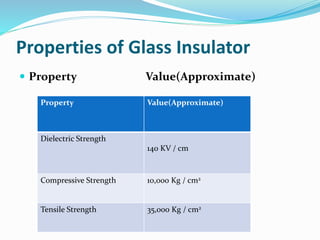
- 16. Properties of Glass Insulator Property Value(Approximate) Property Value(Approximate) Dielectric Strength 140 KV / cm Compressive Strength 10,000 Kg / cm2 Tensile Strength 35,000 Kg / cm2
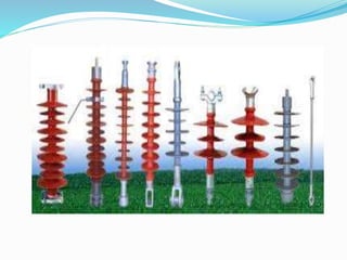
- 17. Polymer Insulator In a polymer insulator has two parts, one is glass fiber reinforced epoxy resin rod shaped core and other is silicone rubber or EPDM (Ethylene Propylene Diene Monomer) made weather sheds. Rod shaped core is covered by weather sheds. Weather sheds protect the insulator core from outside environment. As it is made of two parts, core and weather sheds, polymer insulator is also called composite insulator. The rod shaped core is fixed with Hop dip galvanized cast steel made end fittings in both sides.
- 20. Advantages of Polymer Insulator 1. It is very light weight compared to porcelain and glass insulator. 2. As the composite insulator is flexible the chance of breakage becomes minimum. 3. Because of lighter in weight and smaller in size, this insulator has lower installation cost. 4. It has higher tensile strength compared to porcelain insulator. 5. Its performance is better particularly in polluted areas. 6. Due to lighter weight polymer insulator imposes less load to the supporting structure. 7. Less cleaning is required due to hydrophobic nature of the insulator.
- 21. Disadvantages of Polymer Insulator 1. Moisture may enter in the core if there is any unwanted gap between core and weather sheds. This may cause electrical failure of the insulator. 2. Over crimping in end fittings may result to cracks in the core which leads to mechanical failure of polymer insulator.
- 22. There are several types of insulators but the most commonly used are : 1) Pin Insulator 2) Suspension Insulator 3) Strain Insulator and 4) Shackle insulator.
- 24. A pin insulator consists of a nonconducting material such as porcelain, glass, plastic, polymer, or wood. As the name suggests, the pin type insulator is secured to the cross-arm on the pole. There is a groove on the upper end of the insulator for housing the conductor. The conductor passes through this groove and is bound by the annealed wire of the same material as the conductor. Pin type insulators are used for transmission and distribution of electric power at voltages upto 33 kV. Beyond operating voltage of 33 kV, the pin type insulators become too bulky and hence uneconomical
- 25. Pin Insulator
- 27. For high voltages (>33 kV), it is a usual practice to use suspension type insulators consist of a number of porcelain discs connected in series by metal links in the form of a string. The conductor is suspended at the bottom end of this string while the other end of the string is secured to the cross-arm of the tower. Each unit or disc is designed for low voltage, say 11 kV. The number of discs in series would obviously depend upon the working voltage. For instance, if the working voltage is 66 kV, then six discs in series will be provided on the string.
- 30. When there is a dead end of the line or there is corner or sharp curve, the line is subjected to greater tension. In order to relieve the line of excessive tension, strain insulators are used. For low voltage lines (< 11 kV), shackle insulators are used as strain insulators. However, for high voltage transmission lines, strain insulator consists of an assembly of suspension insulators as shown in Figure. The discs of strain insulators are used in the vertical plane. When the tension in lines is exceedingly high, at long river spans, two or more strings are used in parallel.
- 32. Efficiency of string efficiency=Voltage across the string (n ×Voltage across disc nearest to conductor) Where n = number of discs in the strin
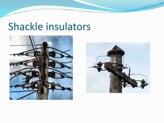
- 34. In early days, the shackle insulators were used as strain insulators. But now a days, they are frequently used for low voltage distribution lines. Such insulators can be used either in a horizontal position or in a vertical position. They can be directly fixed to the pole with a bolt or to the cross arm.
- 36. Causes of Insulator Failure There are different causes due to which failure of insulation in electrical power system may occur 1- Cracking of Insulator The porcelain insulator mainly consists of three different materials. The main porcelain body, steel fitting arrangement and cement to fix the steel part with porcelain. Due to changing climate conditions, these different materials in the insulator expand and contract in different rate. These unequal expansion and contraction of porcelain, steel and cement are the chief cause of cracking of insulator. 2- Defective Insulation Material If the insulation material used for insulator is defective anywhere, the insulator may have a high chance of being puncher from that place.
- 37. . 2- Porosity in The Insulation Materials If the porcelain insulator is manufactured at low temperatures, it will make it porous, and due to this reason it will absorb moisture from air thus its insulation will decrease and leakage current will start to flow through the insulator which will lead to insulator failure. 3-Improper Glazing on Insulator Surface If the surface of porcelain insulator is not properly glazed, moisture can stick over it. This moisture along with deposited dust on the insulator surface, produces a conducting path. As a result the flash over distance of the insulator is reduced. As the flash over distance is reduced, the chance of failure of insulator due to flash over becomes more.
- 38. . 4- Flash Over Across Insulator If flash over occurs, the insulator may be over heated which may ultimately results into shuttering of it. 5- Mechanical Stresses on Insulator If an insulator has any weak portion due to manufacturing defect, it may break from that weak portion when mechanical stress is applied on it by its conductor. These are the main causes of insulator failure. Now we will discuss the different insulator test procedures to ensure minimum chance of failure of insulation.
- 39. Insulator Testing the electrical insulator must undergo the following tests 1. Flashover tests of insulator, 2. Performance tests and 3. Routine tests
- 40. Flashover Test There are mainly 4 types of flashover test performed on an insulator Power Frequency Dry Flashover Test of Insulator 1. First the insulator to be tested is mounted in the manner in which it would be used practically. 2. Then terminals of variable power frequency voltage source are connected to the both electrodes of the insulator. 3. Now the power frequency voltage is applied and gradually increased up to the specified value. This specified value is below the minimum flashover voltage. 4. This voltage is maintained for one minute and observe that there should not be any flash-over or puncher occurred. The insulator must be capable of sustaining the specified minimum voltage for one minute without flash over.
- 41. Cont.. Power Frequency Wet Flashover Test or Rain Test of Insulator 1. In this test also the insulator to be tested is mounted in the manner in which it would be used practically. 2. Then terminals of variable power frequency voltage source are connected to the both electrodes of the insulator. 3. After that the insulator is sprayed with water at an angle of 45o in such a manner that its precipitation should not be more 5.08 mm per minute. The resistance of the water used for spraying must be between 9 kΩ 10 11 kΩ per cm3 at normal atmospheric pressure and temperature. In this way we create artificial raining condition. 4. Now the power frequency voltage is applied and gradually increased up to the specified value. 5. This voltage is maintained for either one minute or 30 second as specified and observe that there should not be any flash-over or puncher occurred. The insulator must be capable of sustaining the specified minimum power frequency voltage for specified period without flash over in the said wet condition.
- 42. Cont… Power Frequency Flashover Voltage test of Insulator 1. The insulator is kept in similar manner of previous test. 2. In this test the applied voltage is gradually increased in similar to that of previous tests. 3. But in that case the voltage when the surroundings air breaks down, is noted.
- 43. Cont.. Impulse Frequency Flashover Voltage Test of Insulator The overhead outdoor insulator must be capable of sustaining high voltage surges caused by lightning etc. So this must be tested against the high voltage surges. 1. The insulator is kept in similar manner of previous test. 2. Then several hundred thousands Hz very high impulse voltage generator is connected to the insulator. 3. Such a voltage is applied to the insulator and the spark over voltage is noted. The ratio of this noted voltage to the voltage reading collected from power frequency flashover voltage test is known as impulse ratio of insulator. This ratio should be approximately 1.4 for pin type insulator and 1.3 for suspension type insulators.
- 44. Performance Test of Insulator Now we will discuss performance test of insulator one by one- Temperature Cycle Test of Insulator 1. The insulator is first heated in water at 70oC for one hour. 2. Then this insulator immediately cooled in water at 7oC for another one hour. 3. This cycle is repeated for three times. 4. After completion of these three temperature cycles, the insulator is dried and the glazing of insulator is thoroughly observed. After this test there should not be any damaged or deterioration in the glaze of the insulator surface. Puncture Voltage Test of Insulator 1. The insulator is first suspended in an insulating oil. 2. Then voltage of 1.3 times of flash over voltage, is applied to the insulator. A good insulator should not puncture under this condition.
- 45. Cont Porosity Test of Insulator 1. The insulator is first broken into pieces. 2. Then These broken pieces of insulator are immersed in a 0.5 % alcohol solution of fuchsine dye under pressure of about 140.7 kg ⁄ cm2 for 24 hours. 3. After that the sample are removed and examine. The presence of a slight porosity in the material is indicated by a deep penetration of the dye into it. Mechanical Strength Test of Insulator 1. The insulator is applied by 2½ times the maximum working strength for about one minute. The insulator must be capable of sustaining this much mechanical stress for one minute without any damage in it.
- 46. Routine Test of Insulator Each of the insulator must undergo the following routine test before they are recommended for using at site. Proof Load Test of Insulator In proof load test of insulator, a load of 20% in excess of specified maximum working load is applied for about one minute to each of the insulator. Corrosion Test of Insulator In corrosion test of insulator, 1. The insulator with its galvanized or steel fittings is suspended into a copper sulfate solution for one minute. 2. Then the insulator is removed from the solution and wiped, cleaned. 3. Again it is suspended into the copper sulfate solution for one minute. 4.The process is repeated for four times.
- 47. Arcing horns "Arcing horns" are projecting conductors used to protect insulators on high voltage electric power transmission systems from damage during flashover. Overvoltages on transmission lines, due to atmospheric electricity, lightning strikes, or electrical faults, can cause arcs across insulators that can damage them
- 48. Arcing horns