

![As such, clinicians and researchers, device manufacturers, and reg-
ulatory agencies all stand to benefit from these standards, because
they will bring greater uniformity into clinical care, clinical trial design,
and the conduct of imaging core laboratories.
Finally, the echocardiographic and Doppler study of patients
before and after surgical and transcatheter therapies involving the
IAS also requires guidelines and standardization of the methodology.
The results of these therapies and their complications must be fully
and competently assessed, characterized, and reported by the mod-
ern echocardiography laboratory.
DEVELOPMENT AND ANATOMY OF THE ATRIAL SEPTUM
Normal Anatomy
Understanding atrial septal communications requires comprehension
of the underlying development and anatomy of the IAS.13
The atrial
septum has three components: the septum primum, septum secun-
dum, and atrioventricular (AV) canal septum. The sinus venosus is
not a component of the true atrial septum but is an adjacent structure
through which an atrial communication can occur.14
Septal defects
can be classified according to their anatomic location in the IAS
(Figure 1).
Figure 2 depicts a schematic of normal atrial septal development.
The atria first develop as a common cavity. At approximately
28 days of gestation, the septum primum, derived from the atrial
roof, begins to migrate toward the developing endocardial cushions.
During this transition, the space between the septum primum and
the endocardial cushion is termed the ‘‘embryonic ostium primum’’
or the ‘‘foramen primum.’’14
The septum secundum, in contrast, is
an infolding of the atrial roof rather than a true membranous struc-
ture; it develops adjacent to the developing truncus and to the right
of the septum primum.14
In the normal heart, the ostium primum
closes by fusion of the mesenchymal cells of the septum primum
(the so-called mesenchymal cap of the vestibular spine) with the supe-
rior and inferior endocardial cushions.14
The leading edge of the
septum secundum becomes the superior limbic band. By 2 months
into gestation, the septum secundum and septum primum fuse, leav-
ing the foramen ovale as the only residual communication. The flap of
the foramen ovale is termed the ‘‘fossa ovalis’’ and is formed by the
septum secundum, septum primum (which attaches on the left atrial
[LA] side of the septum secundum), and the AV canal septum.15
The
septum primum becomes contiguous with the systemic venous tribu-
taries to form the inflow of the superior and inferior vena cavae. The
sinus venosus septum is an adjacent structure to the atrial septum that
separates the right pulmonary veins from the superior vena cava
(SVC) and posterior right atrium (RA).15
The coronary sinus is sepa-
rated from the LA by a wall of tissue called the coronary sinus septum.
The anterosuperior portion of the atrial septum is adjacent to the right
aortic sinus of Valsalva. A more detailed description of atrial septum
development is available for additional information.14
Anatomy of Atrial Septal Defects and Associated Atrial
Septal Abnormalities
Patent Foramen Ovale. A (PFO is not a true deficiency of atrial
septal tissue but rather a potential space or separation between the
septum primum and septum secundum located in the anterosuperior
portion of the atrial septum (Figure 3A,B).16
It is not considered a true
ASD, because no structural deficiency of the atrial septal tissue is pre-
sent.14,17
The foramen remains functionally closed as long as the LA
pressure is greater than the RA pressure. In many cases, a PFO might
be only functionally patent and have a tunnel-like appearance,
because the septum primum forms a flap valve. The relative differ-
ences in left and RA pressure can result in intermittent shunting of
blood. A PFO can also be a circular or elliptical true opening between
the two atria. Some cases of PFO result from ‘‘stretching’’ of the supe-
rior limbic band of the septum secundum from atrial dilation and re-
modeling (Figures 4–6). In other cases, the septum primum is truly
aneurysmal and as such cannot completely close the atrial
communication18
(Figure 7). In fetal life, patency of the foramen ovale
is essential to provide oxygenated blood from the placenta to the vital
organs, including the developing central nervous system.18
After birth,
the foramen ovale generally closes within the first 2 months of age. Up
to 20%–25% of the normal population has a PFO present in adult-
hood.18-21
The incidence and size of a PFO can change with age. In an autopsy
study of 965 human hearts, the overall incidence of PFO was 27.3%,
but it progressively declined with increasing age from 34.3% during
the first 3 decades of life to 25.4% during the 4th through 8th decades
and 20.2% during the 9th and 10th decades.5
The size of a PFO on
autopsy in that series ranged from 1 to 19 mm in the maximal diam-
eter (mean 4.9 mm). In 98% of these cases, the foramen ovale was
1–10 mm in diameter. The size tended to increase with increasing
age, from a mean of 3.4 mm in the first decade to 5.8 mm in the
10th decade of life.5
For purposes of consistency in nomenclature, a ‘‘patent foramen
ovale’’ has been referred to when right to left shunting of blood has
been demonstrated by Doppler or saline contrast injection without
a true deficiency of the IAS. A ‘‘PFO with left to right flow’’ has
been referred to when the atrial hemodynamics have resulted in
opening the potential communication of the foramen, resulting in
left to right shunting of blood demonstrated by Doppler imaging
(Figures 4–6). When a PFO is stretched open by atrial
hemodynamics, thus creating a defect in the septum, it is referred
to as a ‘‘stretched’’ PFO. This can result in left to right or right to left
shunting of blood flow demonstrated by Doppler, depending on
the differences in the right and LA pressure.
Closure of the foramen ovale occurs by fusion of the septum pri-
mum and septum secundum at the caudal limit of the zone of overlap
Figure 1 Subtypes of atrial septal communications when
viewed from RA. PFO not illustrated.
912 Silvestry et al Journal of the American Society of Echocardiography
August 2015](https://image.slidesharecdn.com/2015asd-pfo-221129131810-614b431a/85/2015_ASD-PFO-pdf-3-320.jpg)


![An ostium secundum ASD is often amenable to percutaneous
transcatheter closure.30-33
The evaluation for the suitability of
transcatheter closure is reviewed in detail in the present document.
A rare form of ostium secundum ASD occurs when the superior
limbic band of the septum secundum is absent. In such cases, the atrial
communication is ‘‘high’’ in the septum, in close proximity to the SVC.
However, these defects should not be confused with the sinus veno-
sus defect of the SVC type. Importantly, the high ostium secundum
ASD is not associated with anomalous pulmonary venous return.
An absence of the septum secundum can also occur in the presence
of left-sided juxtaposition of the atrial appendages. Juxtaposition of
the atrial appendages describes the condition in which both atrial ap-
pendages (or one appendage and part of the other) lie beside each
other and to one side of the great arterial vessels. The juxtaposition
is commonly associated with significant congenital heart disease,
including transposition of the great vessels.34
In juxtaposition, the
normal infolding of the atrial roof (that forms the septum secundum)
often does not occur because the great arteries are positioned abnor-
mally (such as is seen with a double outlet ventricle or transposition of
the great arteries).18
Although these defects do not involve the vena
cavae, AV valves, pulmonary veins, or coronary sinus, it is important
to recognize how close the defect is to these surrounding structures
when considering catheter-based device closure.31
Ostium Primum Atrial Septal Defect. An ostium primum ASD
is a congenital anomaly that exists within the spectrum of an AV canal
defect (Figure 13). In early embryologic development, these defects
occur when the endocardial cushions fail to fuse because of abnormal
migration of mesenchymal cells.35
With an endocardial cushion
defect, the canal portion of the AV septum and the AV valves can
all be variably affected. Ostium primum ASD is otherwise known as
partial or incomplete AV canal defect; these names are used inter-
changeably. The defect is characterized by an atrial communication re-
sulting from absence of the AV canal portion of the atrial septum in
association with a common AV valve annulus and two AV valve ori-
fices. The AV valve tissue is adherent to the crest of the ventricular
septum such that no ventricular level shunt is present. The leaflets of
the two AV valves are abnormal with two bridging leaflets that straddle
from the RV to the left ventricle (LV) rather than a normal anterior
mitral valve leaflet and septal tricuspid valve leaflet. The bridging leaf-
lets (superior and inferior) meet at the ventricular septum and are thus
often erroneously termed ‘‘cleft mitral valve.’’ This term is indelibly in
the lexicon of congenital heart disease. However, it is more accurate to
use the left and right AV valves when describing an ostium primum
ASD because both valves will always be abnormal in this setting. AV
valve regurgitation through the so-called cleft is extremely common
because of an abnormality or absence of valve tissue.
The borders of an ostium primum ASD include the septum pri-
mum superiorly and posteriorly and the common AV valve annulus
anteriorly. Because these communications have the AV valve orifice
as one of the margins, percutaneous transcatheter device closure is
not possible.31
Sinus Venosus Defects. Sinus venosus defects are less common
than ostium secundum ASDs and are not true ASDs.28
These defects
occur as a result of a partial or complete absence of the sinus venosus
septum between the SVC and the right upper pulmonary vein (SVC
type) or the right lower and middle pulmonary veins and the RA (infe-
rior vena cava [IVC] type; Figures 14–16). In most cases of sinus
venosus defects of the SVC type, the right upper pulmonary vein is
connected normally but drains anomalously to the RA. However, in
some cases, the right pulmonary vein or veins will be abnormally
connected to the SVC superior to the RA. The shunt that occurs is
therefore similar to that seen in a partial anomalous pulmonary
venous connection in that the pulmonary venous flow is directed
toward the RA. The resulting left-to-right shunt is typically large.
Occasionally, the patient will be mildly desaturated because SVC
blood is able to enter the LA. Sinus venosus defects of the IVC type
Figure 6 (A) Two-dimensional ICE of a ‘‘stretched’’ PFO and (B) with color Doppler in an adult patient. Yellow arrow indicates the
septum secundum; white arrow, septum primum; blue arrow, left to right flow through PFO. See also Video 2.
Journal of the American Society of Echocardiography
Volume 28 Number 8
Silvestry et al 915](https://image.slidesharecdn.com/2015asd-pfo-221129131810-614b431a/85/2015_ASD-PFO-pdf-6-320.jpg)


2015_ASD-PFO.pdf
- 1. ASE GUIDELINES & STANDARDS Guidelines for the Echocardiographic Assessment of Atrial Septal Defect and Patent Foramen Ovale: From the American Society of Echocardiography and Society for Cardiac Angiography and Interventions Frank E. Silvestry, MD, FASE, Chair, Meryl S. Cohen, MD, FASE, Co-Chair, Laurie B. Armsby, MD, FSCAI, Nitin J. Burkule, MD, DM, FASE, Craig E. Fleishman, MD, FASE, Ziyad M. Hijazi, MD, MPH, MSCAI, Roberto M. Lang, MD, FASE, Jonathan J. Rome, MD, and Yan Wang, RDCS, Philadelphia, Pennsylvania; Portland, Oregon; Thane, India; Orlando, Florida; Doha, Qatar; and Chicago, Illinois (J Am Soc Echocardiogr 2015;28:910-58.) TABLE OF CONTENTS Target Audience 911 Objectives 911 Introduction 911 Development and Anatomy of the Atrial Septum 912 Normal Anatomy 912 Anatomy of Atrial Septal Defects and Associated Atrial Septal Abnormalities 912 Patent Foramen Ovale 912 Ostium Secundum Atrial Septal Defect 913 Ostium Primum Atrial Septal Defect 915 Sinus Venosus Defects 915 Coronary Sinus Defects 916 Common Atrium 916 Atrial Septal Aneurysm 916 Eustachian Valve and Chiari Network 916 Imaging of the Interatrial Septum 917 General Imaging Approach 917 Three-Dimensional Imaging of the Interatrial Septum 917 Role of Echocardiography in Percutaneous Transcatheter Device Closure 917 Transthoracic Echocardiography Imaging Protocol for Imaging the Interatrial Septum 924 Subxiphoid Frontal (Four-Chamber) TTE View 924 Subxiphoid Sagittal TTE View 924 Left Anterior Oblique TTE View 924 Apical Four-Chamber TTE View 924 Modified Apical Four-Chamber TTE View (Half Way in Between Apical Four-Chamber and Parasternal Short-Axis View) 924 Parasternal Short-Axis TTE View 924 High Right Parasternal View 924 Transesophageal Echocardiography Imaging Protocol for the Interatrial Septum 925 Upper Esophageal Short-Axis View 925 Midesophageal Aortic Valve Short-Axis View 926 Midesophageal Four-Chamber View 926 Midesophageal Bicaval View 926 Mid-Esophageal Long-Axis View 926 3D TEE Acquisition Protocol for PFO and ASD 927 3D TTE Acquisition Protocol for PFO and ASD 927 3D Display 927 Intracardiac Echocardiographic Imaging Protocol for IAS 928 Assessment of Shunting 928 Techniques, Standards, and Characterization Visualization of Shunting: TTE and TEE 928 Transcranial Doppler Detection/Grading of Shunting 931 Impact of Shunting on the Right Ventricle 932 Pulmonary Artery Hypertension 935 RV Function 935 From the Hospital of the University of Pennsylvania, Perelman School of Medicine, Philadelphia, Pennsylvania (F.E.S.); Children’s Hospital of Philadelphia, Perelman School of Medicine, Philadelphia, Pennsylvania (M.S.C., J.J.R., Y.W.); Doernbecher Children’s Hospital, Oregon Health and Sciences University, Portland, Oregon (L.B.A.); Jupiter Hospital, Thane, India (N.J.B.); Arnold Palmer Hospital for Children, University of Central Florida College of Medicine, Orlando, Florida (C.E.F.); Sidra Medical and Research Center, Doha, Qatar (Z.M.H.); and University of Chicago Hospital, University of Chicago School of Medicine, Chicago, Illinois (R.M.L.). The following authors reported no actual or potential conflicts of interest in relation to this document: Frank E. Silvestry, MD, FASE Chair, Meryl S. Cohen, MD, FASE Co-Chair, Laurie B. Armsby, MD, FSCAI, Nitin J. Burkule, MD, DM, FASE, Jona- than J. Rome, MD, and Yan Wang, RDCS. The following authors reported relation- ships with one or more commercial interests: Craig E. Fleishman, MD, FASE, has served as a consultant for W.L. Gore Medical; Ziyad M. Hijazi MD, MPH, MSCAI has served as a consultant for Occlutech; Roberto M. Lang, MD, FASE, has received grant support and served on the speakers bureau and advisory board for Philips. Attention ASE Members: The ASE has gone green! Visit www.aseuniversity.org to earn free continuing medical education credit through an online activity related to this article. Certificates are available for immediate access upon successful completion of the activity. Nonmembers will need to join the ASE to access this great member benefit! Reprint requests: American Society of Echocardiography, 2100 Gateway Centre Boulevard, Suite 310, Morrisville, NC 27560 (E-mail: ase@asecho.org). 0894-7317/$36.00 Copyright 2015 by the American Society of Echocardiography. http://dx.doi.org/10.1016/j.echo.2015.05.015 910
- 2. LV Function 935 Imaging of IAS and Septal Defects 935 Patent Foramen Ovale 935 Atrial Septal Aneurysm 938 Eustachian Valve and Chiari Network 938 Assessment of ASDs: Standards and Characterization 939 Role of Echocardiography in Transcatheter Device Closure 941 Description of Available Transcatheter Devices and Techniques 942 Device Embolization and Erosion 944 Imaging Modalities in Transcatheter Guidance: TTE, TEE, ICE 947 Intraprocedural Guidance of Transcatheter Interventions 949 ICE Guidance of PTC 950 Imaging the IAS Immediately After the Procedure 951 Follow-Up 953 Conclusion 953 Notice and Disclaimer 954 References 954 TARGET AUDIENCE This document is designed for those with a primary interest and knowledge base in the field of echocardiography and for other medical professionals with a specific interest in the abnor- malities of the interatrial septum and the use of cardiac ultraso- nography. This includes cardio- vascular physicians, other cardiovascular providers, cardiac sonographers, surgeons, cardiac interventionalists, neurologists, residents, research nurses, clini- cians, intensivists, and other medical professionals. OBJECTIVES On completing the reading of the proposed guideline, the par- ticipants will better be able to 1. Describe the conventional two- dimensional, three-dimensional, and Doppler echocardiographic methodology required for optimal evalua- tion and characterization of the interatrial septum from transthoracic echo- cardiographic, transesophageal echocardiographic, and intracardiac echocardiographic ultrasound technologies. 2. Describe the echocardiographic parameters to characterize the normal in- teratrial septum and the abnormalities of atrial septal defect, atrial septal aneurysm, and patent foramen ovale. This will include the best practices for measurement and assessment techniques. 3. Identify the advantages and disadvantages of each echocardiographic tech- nique and measurements of the interatrial septum as supported by the avail- able published data. 4. Recognize which images should be used and measurements that should be included in the standard echocardiographic evaluation of patients with atrial septal defect, atrial septal aneurysm, and patent foramen ovale. 5. Explain the clinical and prognostic significance of the echocardiographic assessment of atrial septal defect, atrial septal aneurysm, and patent fora- men ovale, including not only the interatrial septum assessment, but also evaluation of the chamber size and function and the pulmonary circulation. 6. Recognize what are the relevant features used to evaluate patients for po- tential transcatheter (i.e., device) closure of atrial septal abnormalities. 7. Describe the important features and potential findings in the echocardio- graphic assessment of the patient after surgical and transcatheter interven- tions for atrial septal abnormalities. INTRODUCTION Atrial septal communications account for approximately 6%–10% of congenital heart defects, with an incidence of 1 in 1,500 live births.1 The atrial septal defect (ASD) is among the most common acyanotic congenital cardiac lesions, occurring in 0.1% of births and accounting for 30%–40% of clinically important intracardiac shunts in adults.2-4 The patent foramen ovale (PFO) is more common and is present in greater than 20%–25% of adults.5 The clinical syndromes associated with ASD and PFO are extremely variable and represent a significant health burden that spans pediatric and adult medicine, neurology, and surgery. The evaluation of abnormalities of the interatrial septum and their associated syndromes require a standardized, systematic approach to their echocardiographic and Doppler characterization, including the use of transthoracic echocardiographic (TTE), transeso- phageal echocardiographic (TEE), and intracardiac echocardiographic (ICE) ultrasound, three-dimensional (3D) imaging, Doppler, and transcranial Doppler (TCD) modalities. A thorough echocardiographic evaluation of PFO and ASD in- cludes the detection and quantification of the size and shape of the septal defects, the rims of tissue surrounding the defect, the degree and direction of shunting, and the remodeling and changes in size and function of the cardiac chambers and pulmonary circulation. The emergence of 3D visualization, especially with the TEE-based characterization of septal abnormalities has contributed incremental information in the evaluation of the interatrial septum.6,7 As such, a guideline document to integrate the available diagnostic modalities is presented to aid clinical practice, training, and research. Previous American Society of Echocardiography (ASE) guidelines have focused on the description of performing a comprehensive trans- esophageal examination, standards for acquisition and presentation of 3D echocardiographic imaging, echocardiographic guidance of intera- trial defect device closure,and assessmentofthe right ventricle (RV).8-12 Guidelines for the comprehensive assessment of the interatrial septum (IAS) have the potential to reduce variation in the quality of echocardiographic studies, guide the complete characterization of defects, standardize the measurements and techniques used to describe the anatomy and physiology, and improve the assessment of suitability for surgical and transcatheter therapies. Abbreviations 2D = Two-dimensional 3D = Three-dimensional AoV = Aortic valve ASA = Atrial septal aneurysm ASD = Atrial septal defect ASO = Amplatzer septal occluder AV = Atrioventricular CS = Coronary sinus EV = Eustachian valve DTI = Doppler tissue imaging FDA = Food and Drug Administration IAS = Interatrial septum/ septal ICE = Intracardiac echocardiography IVC = Inferior vena cava LA = Left atrium/atrial LV = Left ventricle/ventricular PA = Pulmonary artery PFO = Patent foramen ovale Qp/Qs ratio = Pulmonary to systemic blood flow ratio RA = Right atrium/atrial RT3DE = Real-time three- dimensional echocardiography RUPV = Right upper pulmonary vein RV = Right ventricle/ ventricular SCAI = Society for Cardiac Angiography and Intervention SVC = Superior vena cava SVD = Sinus venosus defect TCD = Transcranial Doppler TEE = Transesophageal echocardiography/ echocardiographic TTE = Transthoracic echocardiography/ echocardiographic VTI = Velocity time integral Journal of the American Society of Echocardiography Volume 28 Number 8 Silvestry et al 911
- 3. As such, clinicians and researchers, device manufacturers, and reg- ulatory agencies all stand to benefit from these standards, because they will bring greater uniformity into clinical care, clinical trial design, and the conduct of imaging core laboratories. Finally, the echocardiographic and Doppler study of patients before and after surgical and transcatheter therapies involving the IAS also requires guidelines and standardization of the methodology. The results of these therapies and their complications must be fully and competently assessed, characterized, and reported by the mod- ern echocardiography laboratory. DEVELOPMENT AND ANATOMY OF THE ATRIAL SEPTUM Normal Anatomy Understanding atrial septal communications requires comprehension of the underlying development and anatomy of the IAS.13 The atrial septum has three components: the septum primum, septum secun- dum, and atrioventricular (AV) canal septum. The sinus venosus is not a component of the true atrial septum but is an adjacent structure through which an atrial communication can occur.14 Septal defects can be classified according to their anatomic location in the IAS (Figure 1). Figure 2 depicts a schematic of normal atrial septal development. The atria first develop as a common cavity. At approximately 28 days of gestation, the septum primum, derived from the atrial roof, begins to migrate toward the developing endocardial cushions. During this transition, the space between the septum primum and the endocardial cushion is termed the ‘‘embryonic ostium primum’’ or the ‘‘foramen primum.’’14 The septum secundum, in contrast, is an infolding of the atrial roof rather than a true membranous struc- ture; it develops adjacent to the developing truncus and to the right of the septum primum.14 In the normal heart, the ostium primum closes by fusion of the mesenchymal cells of the septum primum (the so-called mesenchymal cap of the vestibular spine) with the supe- rior and inferior endocardial cushions.14 The leading edge of the septum secundum becomes the superior limbic band. By 2 months into gestation, the septum secundum and septum primum fuse, leav- ing the foramen ovale as the only residual communication. The flap of the foramen ovale is termed the ‘‘fossa ovalis’’ and is formed by the septum secundum, septum primum (which attaches on the left atrial [LA] side of the septum secundum), and the AV canal septum.15 The septum primum becomes contiguous with the systemic venous tribu- taries to form the inflow of the superior and inferior vena cavae. The sinus venosus septum is an adjacent structure to the atrial septum that separates the right pulmonary veins from the superior vena cava (SVC) and posterior right atrium (RA).15 The coronary sinus is sepa- rated from the LA by a wall of tissue called the coronary sinus septum. The anterosuperior portion of the atrial septum is adjacent to the right aortic sinus of Valsalva. A more detailed description of atrial septum development is available for additional information.14 Anatomy of Atrial Septal Defects and Associated Atrial Septal Abnormalities Patent Foramen Ovale. A (PFO is not a true deficiency of atrial septal tissue but rather a potential space or separation between the septum primum and septum secundum located in the anterosuperior portion of the atrial septum (Figure 3A,B).16 It is not considered a true ASD, because no structural deficiency of the atrial septal tissue is pre- sent.14,17 The foramen remains functionally closed as long as the LA pressure is greater than the RA pressure. In many cases, a PFO might be only functionally patent and have a tunnel-like appearance, because the septum primum forms a flap valve. The relative differ- ences in left and RA pressure can result in intermittent shunting of blood. A PFO can also be a circular or elliptical true opening between the two atria. Some cases of PFO result from ‘‘stretching’’ of the supe- rior limbic band of the septum secundum from atrial dilation and re- modeling (Figures 4–6). In other cases, the septum primum is truly aneurysmal and as such cannot completely close the atrial communication18 (Figure 7). In fetal life, patency of the foramen ovale is essential to provide oxygenated blood from the placenta to the vital organs, including the developing central nervous system.18 After birth, the foramen ovale generally closes within the first 2 months of age. Up to 20%–25% of the normal population has a PFO present in adult- hood.18-21 The incidence and size of a PFO can change with age. In an autopsy study of 965 human hearts, the overall incidence of PFO was 27.3%, but it progressively declined with increasing age from 34.3% during the first 3 decades of life to 25.4% during the 4th through 8th decades and 20.2% during the 9th and 10th decades.5 The size of a PFO on autopsy in that series ranged from 1 to 19 mm in the maximal diam- eter (mean 4.9 mm). In 98% of these cases, the foramen ovale was 1–10 mm in diameter. The size tended to increase with increasing age, from a mean of 3.4 mm in the first decade to 5.8 mm in the 10th decade of life.5 For purposes of consistency in nomenclature, a ‘‘patent foramen ovale’’ has been referred to when right to left shunting of blood has been demonstrated by Doppler or saline contrast injection without a true deficiency of the IAS. A ‘‘PFO with left to right flow’’ has been referred to when the atrial hemodynamics have resulted in opening the potential communication of the foramen, resulting in left to right shunting of blood demonstrated by Doppler imaging (Figures 4–6). When a PFO is stretched open by atrial hemodynamics, thus creating a defect in the septum, it is referred to as a ‘‘stretched’’ PFO. This can result in left to right or right to left shunting of blood flow demonstrated by Doppler, depending on the differences in the right and LA pressure. Closure of the foramen ovale occurs by fusion of the septum pri- mum and septum secundum at the caudal limit of the zone of overlap Figure 1 Subtypes of atrial septal communications when viewed from RA. PFO not illustrated. 912 Silvestry et al Journal of the American Society of Echocardiography August 2015
- 4. of these structures. Incomplete fusion results in a pouch-like anatomic region that, in most instances, communicates with the LA cavity.22 The phrase ‘‘LA septal pouch’’ refers to the blind pouch from the re- sidual overlap of the septum primum and septum secundum and has been suggested as a possible location for thrombus formation and em- bolism.23-26 This can mimic LA myxoma.27 Ostium Secundum Atrial Septal Defect. An ostium secundum ASD most often occurs as the result of a true deficiency of septum pri- mum tissue; it is the most common form of a true ASD.28 The supe- rior and posterior margins of the defect are composed of the septum secundum, the anterior margin is composed of the AV canal septum, and the inferior margin is composed of the septum primum and left venous valve of the inferior vena cava.18 These defects can vary in shape and can be elliptical or round (Figure 8). With large ostium secundum defects, the septum primum is often nearly or completely absent. In some cases, persistent strands of septum primum will be present and will cross the defect, resulting in multiple Figure 2 (A) The septum primum grows from the roof of the atria. (B) Fenestrations develop within the septum primum. (C) The septum secundum develops by an infolding of the atrial walls. The ostium secundum acts as a conduit for right-to-left shunting of oxygenated blood. (D) At the anterior superior edge of the fossa ovalis, the primum and secundum septa remain unfused, which con- stitutes a PFO. Arrow denotes blood flowing through the PFO from the embryonic RA to the LA. The blue and pink dots represent the development of the caval and pulmonary venous inflow to the atria. EC, endocardial cushion; FO, fossa ovalis; OP, ostium primum; OS, ostium secundum; SP, septum primum; SS, septum secundum. Reproduced with permission from Calvert et al.16 Figure 3 (A) Photograph of autopsy specimen from LA perspective demonstrating PFO by way of the passage of a metal probe; it also demonstrates adjacent structures. SP, septum primum; SS, septum secundum. Reprinted with permission from Cruz-Gonz alez I, Solis J, Inglessis-Azuaje I, Palacios IF. Patent foramen ovale: current state of the art. Rev Esp Cardiol 2008;61:738-751. (B) The septum primum is dark green, and the septum secundum is light green. A PFO typically exists at the anterior superior border adjacent to the aortic root. The arrow denotes the passage of blood through the PFO from the right to left atrium. Journal of the American Society of Echocardiography Volume 28 Number 8 Silvestry et al 913
- 5. communications and creating multiple fenestrations (Figures 9–12). These ASDs typically range in size from several millimeters to as large as more than 3 cm in diameter. For example, in an autopsy series of 50 patients with secundum ASD, all the defects were classifiable into one of four morphologic categories: (1) virtual absence of the septum primum such that the ASD was the entire fossa ovalis (n = 19, 38%); (2) deficiency of the septum primum (n = 16, 32%); (3) a fenestrated septum primum creating multiple ASDs (n = 2, 4%); and (4) fenestrations in a deficient septum primum creating multiple ASDs (n = 13, 26%).29 These anatomic var- iations can have significant implications for device closure and could favor the use of devices designed for multiple fenestrations or require multiple devices for closure. Secundum ASDs can enlarge over time with age and cardiac growth.28 Figure 4 Two-dimensional TEE of a PFO (yellow arrow) in bicaval views (A) without and (B) with color Doppler in an adult patient. Figure 5 Two-dimensional TEE of a ‘‘stretched’’ PFO (yellow arrow) in bicaval views (A and B) with color Doppler flow from left to right in an adult patient. See also Video 1. 914 Silvestry et al Journal of the American Society of Echocardiography August 2015
- 6. An ostium secundum ASD is often amenable to percutaneous transcatheter closure.30-33 The evaluation for the suitability of transcatheter closure is reviewed in detail in the present document. A rare form of ostium secundum ASD occurs when the superior limbic band of the septum secundum is absent. In such cases, the atrial communication is ‘‘high’’ in the septum, in close proximity to the SVC. However, these defects should not be confused with the sinus veno- sus defect of the SVC type. Importantly, the high ostium secundum ASD is not associated with anomalous pulmonary venous return. An absence of the septum secundum can also occur in the presence of left-sided juxtaposition of the atrial appendages. Juxtaposition of the atrial appendages describes the condition in which both atrial ap- pendages (or one appendage and part of the other) lie beside each other and to one side of the great arterial vessels. The juxtaposition is commonly associated with significant congenital heart disease, including transposition of the great vessels.34 In juxtaposition, the normal infolding of the atrial roof (that forms the septum secundum) often does not occur because the great arteries are positioned abnor- mally (such as is seen with a double outlet ventricle or transposition of the great arteries).18 Although these defects do not involve the vena cavae, AV valves, pulmonary veins, or coronary sinus, it is important to recognize how close the defect is to these surrounding structures when considering catheter-based device closure.31 Ostium Primum Atrial Septal Defect. An ostium primum ASD is a congenital anomaly that exists within the spectrum of an AV canal defect (Figure 13). In early embryologic development, these defects occur when the endocardial cushions fail to fuse because of abnormal migration of mesenchymal cells.35 With an endocardial cushion defect, the canal portion of the AV septum and the AV valves can all be variably affected. Ostium primum ASD is otherwise known as partial or incomplete AV canal defect; these names are used inter- changeably. The defect is characterized by an atrial communication re- sulting from absence of the AV canal portion of the atrial septum in association with a common AV valve annulus and two AV valve ori- fices. The AV valve tissue is adherent to the crest of the ventricular septum such that no ventricular level shunt is present. The leaflets of the two AV valves are abnormal with two bridging leaflets that straddle from the RV to the left ventricle (LV) rather than a normal anterior mitral valve leaflet and septal tricuspid valve leaflet. The bridging leaf- lets (superior and inferior) meet at the ventricular septum and are thus often erroneously termed ‘‘cleft mitral valve.’’ This term is indelibly in the lexicon of congenital heart disease. However, it is more accurate to use the left and right AV valves when describing an ostium primum ASD because both valves will always be abnormal in this setting. AV valve regurgitation through the so-called cleft is extremely common because of an abnormality or absence of valve tissue. The borders of an ostium primum ASD include the septum pri- mum superiorly and posteriorly and the common AV valve annulus anteriorly. Because these communications have the AV valve orifice as one of the margins, percutaneous transcatheter device closure is not possible.31 Sinus Venosus Defects. Sinus venosus defects are less common than ostium secundum ASDs and are not true ASDs.28 These defects occur as a result of a partial or complete absence of the sinus venosus septum between the SVC and the right upper pulmonary vein (SVC type) or the right lower and middle pulmonary veins and the RA (infe- rior vena cava [IVC] type; Figures 14–16). In most cases of sinus venosus defects of the SVC type, the right upper pulmonary vein is connected normally but drains anomalously to the RA. However, in some cases, the right pulmonary vein or veins will be abnormally connected to the SVC superior to the RA. The shunt that occurs is therefore similar to that seen in a partial anomalous pulmonary venous connection in that the pulmonary venous flow is directed toward the RA. The resulting left-to-right shunt is typically large. Occasionally, the patient will be mildly desaturated because SVC blood is able to enter the LA. Sinus venosus defects of the IVC type Figure 6 (A) Two-dimensional ICE of a ‘‘stretched’’ PFO and (B) with color Doppler in an adult patient. Yellow arrow indicates the septum secundum; white arrow, septum primum; blue arrow, left to right flow through PFO. See also Video 2. Journal of the American Society of Echocardiography Volume 28 Number 8 Silvestry et al 915
- 7. are more unusual and typically involve anomalous drainage of the right middle and/or lower pulmonary veins. Sinus venosus defects cannot be closed by device and typically require baffling of the right pulmonary veins to the LA by way of an ASD patch. Reimplantation of the SVC (Warden procedure) is sometimes required if the right pul- monary veins are connected directly to the SVC. Coronary Sinus Defects. A coronary sinus septal defect or an ‘‘unroofed’’ coronary sinus is one of the more rare forms of atrial communication. In this defect, the wall of the coronary sinus within the LA is deficient or completely absent (Figures 17–19). In a heart without other major structural anomalies, LA blood enters the coronary sinus and drains into the RA through the coronary sinus os, which is typically enlarged to accommodate the increased flow. When a patent left SVC is associated with a coronary sinus septal defect, it is termed ‘‘Raghib syndrome.’’36 Contrast injection with agitated saline is often helpful to make the diagnosis. Two-dimensional (2D) and 3D TEE could be particularly useful in establishing the diagnosis and correlating with the surgical findings.6,37 In the setting of partial coronary sinus unroofing, percutaneous transcatheter device closure might be possible in some cases.38,39 Common Atrium. Rarely, all components of the atrial septum, including the septum primum, septum secundum, and AV canal septum are absent, resulting in a common atrium.28,40-42 This is typically seen in association with heterotaxy syndrome. Some remnants of tissue might still be present in these patients. Atrial Septal Aneurysm. An atrial septal aneurysm (ASA) is a redundancy or saccular deformity of the atrial septum and is associated with increased mobility of the atrial septal tissue. ASA is defined as excursion of the septal tissue (typically the fossa ovalis) of greater than 10 mm from the plane of the atrial septum into the RA or LA or a combined total excursion right and left of 15 mm (Figure 10). The prevalence ofASA is 2%–3%.43 ASA has beenassociatedwiththe pres- ence of a PFO, as well as an increased size of a PFO, and an increased prevalence of cryptogenic stroke and other embolic events. ASA has also been associated with multiple septal fenestrations, and this should be evaluated for carefully using color Doppler imaging.44-46 Eustachian Valve and Chiari Network. The eustachian valve is a remnant of the valve of the IVC that, during fetal life, directs IVC flow across the fossa ovalis. A large or prominent eustachian valve in the setting of a PFO might indirectly contribute to paradoxical embolism by preventing spontaneous closure of the foramen.47 The eustachian valve extends anterior from the IVC–RA junction. A Chiari network is a remnant of the right valve of the sinus veno- sus and appears as a filamentous structure in various places in the RA, including near the entry of the IVC and coronary sinus into the RA (Figure 20). A Chiari network is present in 2%–3% of the general population and is associated with the presence of PFO and ASA.48 Figure 7 Biplane TEE of IAS with PFO demonstrating excessive mobility of the fossa ovalis and an associated PFO (arrow). Contrast is seen in the RA. See also Video 3. 916 Silvestry et al Journal of the American Society of Echocardiography August 2015
- 8. KEY POINTS PFO PFO is not a true deficiency of atrial septal tissue but rather a potential space or separation between the septum primum and septum secundum that occurs in up to 20%–25% of the population. PFO is defined by the demonstration of right to left shunting by contrast or color Doppler, and a ‘‘stretched’’ PFO is present when atrial hemodynamics have opened the foramen and result in left to right or right to left shunting demonstrated by Doppler imaging. ASD Ostium secundum ASD occurs as a deficiency in septum primum and is the most common form of ASD. Ostium secundum ASD is often amenable to percutaneous transcatheter closure. Ostium secundum ASD defects can vary in shape and can be elliptical or round and can contain multiple fenestrations. Ostium primum ASD occur as a result a failure of fusion of the endocardial cush- ions and are within the spectrum of AV septal defects. Sinus venosus defects are not true ASDs and result from the absence of sinus ve- nosus septum between right upper pulmonary veins and SVC (SVC type) or right middle and lower pulmonary veins and RA (IVC type). Coronary sinus defects (or unroofed coronary sinus) are not true ASDs and permit a left-to-right shunt from the LA to coronary sinus to the RA. ASA ASA is defined as an excursion of septal tissue of 10 mm from the plane of the atrial septum into the atrium or a total excursion of 15 mm. IMAGING OF THE INTERATRIAL SEPTUM General Imaging Approach The most widely used ultrasound modality to evaluate the IAS is TTE, which remains the preferred initial diagnostic modality for the detec- tion and diagnosis of PFO, ASD, and ASA.20,49-61 TTE is especially useful in small children in whom the ultrasound image quality will typically permit a full diagnostic study. It can also be used for patient selection and real-time transcatheter ASD or PFO closure pro- cedural guidance in pediatric patients.31,57,62-64 TTE can be used for the initial evaluation of ASD and PFO in adults; however, TEE is required to further characterize the atrial septal ab- normalities, because the TTE image quality will not always permit a comprehensive evaluation of the IAS. TEE is not invariably required for assessment of a PFO if transcatheter closure is not being consid- ered. Also, 2D and 3D TEE offers significant incremental anatomic in- formation compared with TTE and should be performed in all adult patients being evaluated for percutaneous transcatheter closure or sur- gical therapy.31,65-67 In adults, TEE can identify the margins or rims of the ASD (see section on Assessment of ASDs: Standards and Characterization) and assess the surrounding structures (e.g., aorta, cavae, pulmonary veins, AV valves, and coronary sinus). ICE has been used extensively to guide percutaneous ASD/PFO closure procedures and provides comparable (but not identical) imag- ing to TEE. ICE is discussed extensively in the subsequent sections (see sections on Intracardiac Echocardiographic Imaging Protocol for IAS and Role of Echocardiography in Transcatheter Device Closure). Contrast echocardiography with agitated saline plays an important role in the evaluation of PFO and assessing residual shunts after trans- catheter closure and has a more limited role in the diagnosis of ASD.52,61,63,68-75 Contrast echocardiography and contrast TCD is discussed further in sections on Assessment of Shunting; Techniques, Standards, and Characterization Visualization of Shunting: TTE and TEE; and Transcranial Doppler Detection/Grading of Shunting. Table 1 summarizes the recommended general imaging approach to atrial septal abnormalities stratified by the patient characteristics, imaging modality, and intended application (e.g., diagnosis, proce- dure selection or guidance, follow-up). Three-Dimensional Imaging of the Interatrial Septum Most recently, 3D TEE has been described to improve the visualiza- tion of PFO and ASD, their surrounding tissue rims, and surrounding structures and can be used for guidance during percutaneous trans- catheter closure.6,7,53,63,65,66,76-81 Because the IAS is a complex, dynamic, and 3D anatomic structure, limitations exist in its evaluation using any single form of 2D echocardiography. The IAS (and associated abnormalities such as ASD or PFO) does not exist in a true flat plane that can be easily aligned or interrogated using 2D imaging. Both ASD and PFO exist in a wide variety of heterogeneous sizes, shapes, and configurations (Figures 8 and 21). Also, 3D imaging provides unique views of the IAS and, in particular, allows for en face viewing of the ASD and surrounding fossa, allowing for accurate determination of the ASD size and shape. Furthermore, 3D imaging offers the potential to clearly and comprehensively define the dynamic morphology of the defect, which has been shown to change during the cardiac cycle. Also, 3D imaging delineates the relationship of the ASD to the surrounding cardiac structures and the rims of tissue surrounding it (Figure 22). Two-dimensional biplane (or triplane) imaging, a feature of currently commercially available 3D imaging systems, is a unique mo- dality that takes advantage of 3D technology. The advantages of biplane imaging include the display of simultaneous additional echo- cardiographic views, with high frame rates and excellent temporal res- olution. Complimentary simultaneously displayed orthogonal plane imaging provides incremental information compared with that from a single plane, and this imaging modality is uniquely suited to trans- catheter procedure guidance. Numerous reports of the advantages of 3D TEE in guiding catheter interventions have been published and include the use of biplane imaging.7,65,66,80,82 Figure 23 illustrates the use of biplane imaging during percutaneous transcatheter closure of ASD before deployment of the device. Also, 3D imaging allows for multiple acquisition modes, including narrow-angle, zoomed, and wide-angle gated acquisition of multiple volumes. Once 3D volumes are acquired, postprocessing using commercially available 3D software packages such as QLAB (Philips, Best, The Netherlands) or 4D Cardio-View (TomTec, Munich, Germany) is performed to align the plane of the IAS with multiple 3D plane slices. This approach facilitates an assessment of the shape of an ASD and allows for measurement of the en face diameters in mul- tiple orthogonal views, without the potential for bias due to malalign- ment of the ultrasound planes (Figure 24). The images should be reviewed in both systole and diastole to assess for the dynamic change in size that can occur. This 3D en face display can also aid in the recog- nition and quantification of rim deficiencies, because the extent of the deficiency relative to the surrounding structures such as the aorta can be easily demonstrated and quantified. The distance between the defect and the aorta can be easily measured, just as can the area of the defect and length of rim deficiency when present. Role of Echocardiography in Percutaneous Transcatheter Device Closure The role of TTE, TEE, and ICE during the assessment and transcatheter management of ASD/PFO is essential.31,63,80,83 Journal of the American Society of Echocardiography Volume 28 Number 8 Silvestry et al 917
- 9. Echocardiography in patients undergoing transcatheter closure is critically important for appropriate patient selection, real-time proce- dure guidance, assessment of device efficacy and complications, and long-term follow-up. TTE provides information about the type of defect, its hemody- namic significance, and any associated anomalies and can be used comprehensively in smaller pediatric patients for the diagnosis of ASD and PFO and for patient selection and procedure guidance. TTE has the advantage of offering unlimited multiple planes to eval- uate the atrial septum, but it has limited ability to interrogate the lower rim of atrial septal tissue above the IVC after device placement because the device shadowing interferes with imaging in virtually all planes. In addition, because the septum is relatively far from the transducer, the image quality is often suboptimal in larger pediatric and adult patients. If percutaneous closure is clinically indicated, a detailed assessment of the IAS anatomy and surrounding structures using TEE is typically required for patient selection and procedure guidance or ICE for procedure guidance in such patients. Figure 8 Three-dimensional TEE images of various shapes and sizes of ostium secundum ASD. Representative examples of (A) round, small, (B) round, large, (C) oval, small, and (D) oval, large secundum ASD. See also Video 4. Reprinted with permission from Seo et al.77 Figure 9 Subxiphoid TTE demonstrating multifenestrated IAS without and with color Doppler flow from left to right in a pediatric pa- tient. See also Video 5. 918 Silvestry et al Journal of the American Society of Echocardiography August 2015
- 10. Transesophageal echocardiography provides real-time, highly detailed imaging of the IAS, surrounding structures, catheters, and closure device during transcatheter closure. It requires either conscious sedation, with the attendant aspiration risk in a supine pa- tient, or general anesthesia, with an endotracheal tube placed to minimize aspiration risk. This approach also requires a dedicated echocardiographer to perform the TEE, while the interventionalist performs the transcatheter closure procedure. The advent of 3D Figure 11 Three-dimensional TEE of one medium and one small ostium secundum ASDs (white arrows). (A) Bicaval view demon- strating two discrete ASDs. (B) Bicaval view with color Doppler demonstrating two discrete left to right shunts. (C) Zoom acquisition of both ASDs en face from RA perspective. (D) Minimally invasive surgical repair demonstrating identical pathologic findings to 3D TEE. Figure 10 Two-dimensional TEE (bicaval view) of IAS with ASA demonstrating excessive mobility of the fossa ovalis (A–C) and asso- ciated multiple fenestrations (D–E) (yellow arrows). Journal of the American Society of Echocardiography Volume 28 Number 8 Silvestry et al 919
- 11. Figure 13 (A) Primum ASD by 2D TTE in apical four-chamber view. (B) Primum ASD by 2D TTE in subcostal left anterior oblique view. CAVV, common AV valve. Figure 12 Three-dimensional TEE of multiple secundum ASDs (white arrows) resulting in a ‘‘Swiss cheese’’ configuration. (A) Bicaval view demonstrating at least two discrete ASDs with left to right color Doppler flow. (B) En face zoom acquisition from RA perspective demonstrating four discrete ASDs. (C) Zoom acquisition after minimally invasive surgical repair with a single pericardial patch. See also Videos 6 and 7. 920 Silvestry et al Journal of the American Society of Echocardiography August 2015
- 12. TEE has enhanced the evaluation of ASD and PFO by clearly defining the IAS anatomy and enables an en face view of the defect and its sur- rounding structures. Multiplanar reconstruction of the 3D data set allows accurate measurement of the minimum and maximum di- mensions of the defect or defects, facilitating selection of the optimal size and type of closure device. Moreover, intraprocedural real-time 3D TEE provides superior visualization of wires, catheters and de- vices, and their relationships to neighboring structures in a format that is generally more intuitively comprehended by the interventional cardiologist (Figure 25). Figure 14 (A) Representative example of 2D TTE (left) and with color Doppler (right) of an SVC type sinus venosus ASD from the high right parasternal view. (B) Representative example of 2D TTE (left) and with color Doppler (right) of an SVC type sinus venosus ASD from the subcostal sagittal view. RPA, right pulmonary artery. See also Video 8. Figure 15 Transthoracic echocardiogram of a SVC type venosus ASD in subxiphoid sagittal view without and with color in a pediatric patient. The yellow arrow represents the right superior pulmonary vein and the white arrow, the defect entering the atrium. See also Video 9. Journal of the American Society of Echocardiography Volume 28 Number 8 Silvestry et al 921
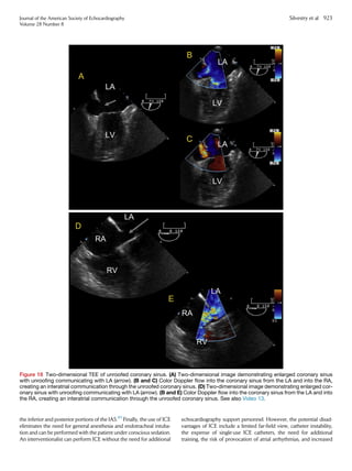
- 13. Intracardiac echocardiography has been used extensively to guide percutaneous ASD/PFO closure procedures and is the imaging modality of choice in many centers in the cardiac catheterization laboratory.84-88 The advantages of ICE include an image quality that is similar (but not identical) to that of TEE, facilitating a comprehensive assessment of the IAS, location and size of the defects, the adequacy of the rims, and location of the pulmonary veins. It also retains an advantage compared with TEE in imaging Figure 16 (A) Inferior vena cava type sinus venosus ASD by 2D TTE (left) and with color Doppler (right) in the parasternal short-axis view with left to right flow. (B) IVC type sinus venosus ASD by 2D TTE in the subcostal view. See also Video 10. Figure 17 (A) Two-dimensional TTE (left) and with color Doppler (right) demonstrating unroofed coronary sinus interatrial communi- cation in four-chamber view. Note dilated CS. (B) Two-dimensional TTE (left) and with color Doppler (right) demonstrating unroofed coronary sinus interatrial communication in subcostal left anterior oblique view. CS, coronary sinus. See also Videos 11 and 12. 922 Silvestry et al Journal of the American Society of Echocardiography August 2015
- 14. the inferior and posterior portions of the IAS.89 Finally, the use of ICE eliminates the need for general anesthesia and endotracheal intuba- tion and can be performed with the patient under conscious sedation. An interventionalist can perform ICE without the need for additional echocardiography support personnel. However, the potential disad- vantages of ICE include a limited far-field view, catheter instability, the expense of single-use ICE catheters, the need for additional training, the risk of provocation of atrial arrhythmias, and increased Figure 18 Two-dimensional TEE of unroofed coronary sinus. (A) Two-dimensional image demonstrating enlarged coronary sinus with unroofing communicating with LA (arrow). (B and C) Color Doppler flow into the coronary sinus from the LA and into the RA, creating an interatrial communication through the unroofed coronary sinus. (D) Two-dimensional image demonstrating enlarged cor- onary sinus with unroofing communicating with LA (arrow). (B and E) Color Doppler flow into the coronary sinus from the LA and into the RA, creating an interatrial communication through the unroofed coronary sinus. See also Video 13. Journal of the American Society of Echocardiography Volume 28 Number 8 Silvestry et al 923
- 15. technical difficulty for a single operator. Table 2 provides a summary of the advantages and disadvantages of TTE, TEE, and ICE in percu- taneous transcatheter guidance of PFO and ASD. Transthoracic Echocardiography Imaging Protocol for Imaging the Interatrial Septum The atrial septum can be evaluated fully using TTE. Ideally, multiple views should be used to evaluate the size, shape, and location of an atrial communication and the relationship of the defect to its sur- rounding structures (Figures 9 and 13–17 and 26–28). In particular, special attention must be paid to determine the relationship of the defect to the venae cavae, pulmonary veins, mitral and tricuspid valves, and coronary sinus. Assessment of the amount of the surrounding rims of tissue present is crucial. A deficiency of rim tissue between the defect and pulmonary veins, AV valve, or IVC will preclude transcatheter closure, and a deficiency of aortic rim can increase the risk of device erosion in certain circumstances. Additional views of other structures such as the ventricles and great arteries are necessary to assess for secondary findings related to the hemodynamic consequences of an ASD such as RA, right ventricular (RV), and pulmonary artery (PA) dilation. In the pediatric population, the subxiphoid window typically allows the best visualization of the atrial septum and its related structures. In adolescence and adulthood, the subxiphoid window is often inadequate because of the distance from the probe to the atrial septum. Thus, other views such as the par- asternal windows should be used to assess the atrial septum. In some cases, a full assessment of the atrial septum might not be possible with TTE. Thus, TEE could be required. Subxiphoid Frontal (Four-Chamber) TTE View. The subxi- phoid frontal (four-chamber) view allows imaging of the atrial septum along its anterior–posterior axis from the SVC to the AV valves. This is the preferred view for imaging the atrial septum, because the atrial septum runs near perpendicularly to the ultrasound beam, providing the highest axial resolution and permitting measurement of the defect diameter along its long axis. Because the septum is thin (especially in its midportion), placing the septum perpendicular to the ultrasound beam helpsdistinguisha true defect fromdropout resultingfroman arti- fact. Aneurysms of the atrial septum primum composed of tissue attached to the edges of the ASD are also well visualized from the sub- costal frontal view. ASAs could be fenestrated (Figure 9) but also can be intact with no resultant atrial level shunt. Color Doppler interrogation and contrast studies should be used to detect shunting. Thesurrounding rimfromthedefecttothe right pulmonary veins can be measuredinthis view. Sinus venosus defects will be difficult to visualize because the venae cavae are not viewed longitudinally in this view. Subxiphoid Sagittal TTE View. Thesubxiphoidsagittal TTE viewis acquired by turning the transducer 90 clockwise from the frontal view. This view is ideal for imaging the atrial septum along its superior–inferior axis in a plane orthogonal to the subxiphoid frontal four-chamber view. Sweeping the transducer from right to left in this axis allows determination of the orthogonal dimension of the ASD (Figures 15 and 17). This dimension can be compared with the dimension measured in the subxiphoid frontal view to help determine the shape (circular or oval) of the defect. This view can be used to measure the rim from the defect to the SVC and IVC and is an excellent window to image a sinus venosus type defect (Figures 14B and 15). Left Anterior Oblique TTE View. The left anterior oblique TTE view is acquired by turning the transducer approximately 45 coun- terclockwise from the frontal (four-chamber) view. This view allows imaging of the length of the atrial septum and is therefore ideal to identify ostium primum ASDs and for assessment of coronary sinus dilation (Figures 13B and 17B). In addition, it allows evaluation of the relation of the SVC to the defect. Furthermore, this view can be used to evaluate the entrance of the right-sided pulmonary veins into the heart. Apical Four-Chamber TTE View. In the apical four-chamber TTE view, the diagnosis and measurement of ASDs should be avoided because the atrial septum is aligned parallel to the ultrasound beam. Thus, artifactual dropout is frequently seen in this view, which could result in overestimation of the defect size. This view is used to assess the hemodynamic consequences of ASDs, such as RA and RV dila- tion, and to estimate RV pressure using the tricuspid valve regurgitant jet velocity. This view is also used to evaluate for right-to-left shunting with agitated saline (Figure 29). Modified Apical Four-Chamber TTE View (Half Way in Be- tween Apical Four-Chamber and Parasternal Short-Axis View). The modified apical four-chamber TTE view is obtained by sliding the transducer medially from the apical four-chamber view to the sternal border. This view highlights the atrial septum at an improved incidence angle to the sound bean (30 –45 ). In the pa- tients in whom the subcostal views are difficult to obtain, the modified apical four-chamber view is an alternative method for imaging the atrial septum in the direction of the axial resolution of the equipment. Parasternal Short-Axis TTE View. In the parasternal short-axis TTE view at the base of the heart, the atrial septum is visualized pos- terior to the aortic root running in an anterior–posterior orientation. This view is ideal to identify the aortic rim of the defect (Figures 26 and 27). It also highlights the posterior rim (or lack thereof) in sinus venosus and posteroinferior secundum defects. The size of the defect itself should not be measured in this view, because the beam orientation is parallel to the septum, and drop out resulting from artifact can occur. High Right Parasternal View. The high right parasternal view is a parasagittal view performed with the patient in the right lateral decu- bitus position with the probe in the superior–inferior orientation. In Figure 19 Unroofed coronary sinus on 3D TEE image as viewed from LA aspect. Oval indicates perimeter of unroofed portion of sinus in LA. 924 Silvestry et al Journal of the American Society of Echocardiography August 2015
- 16. this view, the atrial septum is aligned perpendicular to the beam and is ideal for diagnosing sinus venosus defects, particularly when the sub- xiphoid windows are inadequate (Figure 16). Table 3 summarizes the key imaging views for TTE for the evalua- tion of the IAS and surrounding structures. Transesophageal Echocardiography Imaging Protocol for the Interatrial Septum As with TTE, multiple and sequential TEE views should be used to completely and systematically evaluate the IAS, the size, shape, and location of any atrial communication present, and the relationship of the defect to its surrounding structures. A comprehensive guide to performing multiplane TEE has been previously published by the ASE and the Society of Cardiovascular Anesthesiologists, and should be referred to for recommendations on performing a comprehensive TEE examination.11 We recommend sequential interrogation and the digital capture of images starting from the standard views and then by stepwise in- creases in the transducer angle in a series of 15 increments to pan or sweep the ultrasound beam through the areas of interest. Two- dimensional images should be optimized and color Doppler mapping subsequently applied. The color Doppler scale can be reduced slightly to approximately 35–40 cm/sec to capture low-velocity flow across a small fenestration, PFO, or smaller ASD. Pulsed and continuous wave Doppler should then be used to measure the velocity, direction, and timing of flow in the representative views. Capturing 3D volumes with and without color Doppler of the IAS allows for even greater data acquisition without the need for sequen- tial multiplane interrogation and acquisition and is discussed sepa- rately in the section on 3D TEE Acquisition Protocol for PFO and ASD. When an ASD or PFO is present, attention must be given to deter- mining the relationship of the defect to the venae cavae, pulmonary veins, mitral and tricuspid valves, and coronary sinus. An assessment of the amount of the surrounding rims of tissue is critical for evalua- tion of patient candidacy for percutaneous transcatheter closure. A deficient rim is defined as less than 5 mm in multiple sequential views, and this should be evaluated in at least three sequential related multi- plane views in 15 increments. As with TTE, additional views of the other cardiac structures are necessary to assess for secondary findings related to the hemody- namic consequences of an ASD such as right heart and pulmonary arterial dilation. Please refer to the ASE guidelines on comprehensive TEE assessment and the assessment of the right heart.9-11 When using TEE, five base views are used to assess the IAS and sur- rounding structures, which are summarized in Table 4. These key views include the upper esophageal short-axis view, midesophageal aortic valve (AoV) short-axis view, midesophageal four-chamber view, midesophageal bicaval view, and midesophageal long-axis view. Upper Esophageal Short-Axis View. The upper esophageal short-axis view is obtained from the upper esophagus starting at multi- plane angles of 0 , with stepwise sweeping and recording at 15 , 30 , and 45 . This view facilitates imaging of the superior aspects of the atrial septum, including the septum secundum, the roofs of the RA and LA, and the surrounding great vessels (SVC and ascending aorta). Entry of the right pulmonary veins can be demonstrated by insertion Figure 20 Transthoracic echocardiogram from the RV inflow view demonstrating mobile Chiari network (yellow arrows) attached to eustachian ridge. Table 1 Imaging strategy in overall evaluation of atrial septal abnormalities Patient population Establishing diagnosis of ASD or PFO Imaging for transcatheter procedure guidance Routine postprocedure follow-up study Pediatric patients 35–40 kg TTE or TEE* TEE or ICE† TTE Pediatric patients 35–40 kg TTE, TEE, 3D TEE TEE, 3D TEE, or ICE† TTE Adult patients TTE, TEE, or 3D TEE TEE, 3D TEE, or ICE† TTE *Depending on body surface area and adequacy of image quality, TEE is highly recommended for assessment of an ASD but is generally performed in intubated patients; if the weight is 35–40 kg, 3D TEE can be performed. † Some centers use ICE for procedure guidance of all defects; others use ICE for uncomplicated small ASD closure only, reserving TEE or 3D TEE for complicated or larger septal defects. Journal of the American Society of Echocardiography Volume 28 Number 8 Silvestry et al 925
- 17. into the mid-esophagus and by clockwise rotation of the probe in these views (Figure 30). Anomalous pulmonary venous drainage and an SVC type sinus venosus defect can be noted in this view. Midesophageal Aortic Valve Short-Axis View. The mideso- phageal AoV short-axis view is obtained from the mid-esophagus starting with a multiplane angle of approximately 30 and stepwise sweeping through and recording additional views at 45 , 60 , and 75 . This progression of transducer angles allows transitional interro- gation of the IAS from the AoV short-axis view to the modified bicaval tricuspid valve view. The AoV short-axis view is typically obtained to present short-axis views of the AoV and its surrounding septum. This view facilitates imaging of the anterior and posterior planes of the atrial septum (and aortic and posterior rims if an ASD is present), the ante- roposterior diameter of the ASD, and the overlap of septum primum and septum secundum when a PFO is present (Figures 31 and 32). Midesophageal Four-Chamber View. The midesophageal four- chamber view is obtained from the mid-esophagus beginning with a multiplane angles of 0 and stepwise increases of the multiplane angle to 15 and 30 . This view is used to evaluate the AV septum (deficient in primum ASD) and the relationship of any ASD to the AV valves (Figure 33). Larger devices used to close secundum ASD can interfere or impinge on AV valve function, and this must be carefully evaluated before device deployment (Figure 34). Midesophageal Bicaval View. The midesophageal bicaval view is obtained from the mid-esophagus with multiplane angles of 90 , 105 , and 120 . It is used to image the inferior and superior plane of the atrial septum and the surrounding structures, such as the SVC and right pulmonary veins (Figures 4, 5, 7, 10A–C,11A and B, 12A, 35, and 36). This view is important for evaluating sinus venosus defects of the SVC type and to evaluate for anomalous pulmonary vein insertion. This view is also important in evaluating the roof or dome of the RA, which must be visualized before release of ASD closure devices. Mid-Esophageal Long-Axis View. The midesophageal long-axis view is obtained from the mid-esophagus with multiplane angles of Figure 21 Three-dimensional TEE images of a PFO. (A–C) Excessive movement of the septum primum (fossa ovalis) in a patient with an ASA and a PFO. White arrow indicates PFO opened fully under influence of pressure difference between RA and LA. (D) PFO ‘‘tun- nel’’ as viewed from the LA perspective. Blue arrow indicates the PFO exit into the LA. (E) PFO tunnel exiting into LA (white arrow). Figure 22 Three-dimensional ASD assessment allows for delin- eation of an ASD (blue arrow) and its relationship between adja- cent structures—the aortic valve is seen and the entire aortic rim (white arrow) is visualized en face. 926 Silvestry et al Journal of the American Society of Echocardiography August 2015
- 18. 120 , 135 , and 150 to evaluate the roof or dome of the LA when a percutaneous device is placed (see the section on the Role of Echocardiography in Percutaneous Transcatheter Device Closure). Rotation past the LA appendage demonstrates the entry of the left pulmonary veins into the LA (Figure 37). 3D TEE Acquisition Protocol for PFO and ASD Three-dimensional transesophageal images of the IAS should be ac- quired from multiple views and multiple 3D imaging modes for anal- ysis. A comprehensive description of overall 3D image acquisition, formatting, and presentation can be found in the 2012 ASE guide- lines.12 A comprehensive 3D examination usually begins with a real-time or narrow-angled acquisition from the standard imaging views. To obtain images with higher temporal and spatial resolution, electrocar- diographically gated, 3D wide-angled acquisitions are then per- formed. When evaluating the IAS using TEE, we recommend narrow-angled, zoomed, and wide-angled acquisition of 3D data from several key views: Midesophageal short-axis view: acquired from the mid-esophagus starting at a multiplane angle of 0 . The probe is rotated toward the IAS. This view is particularly suited to narrow- and wide-angled acquisitions. Basal short-axis view: acquired from the mid-esophagus starting at 30 to 60 multiplane angles. This view is particularly suited to narrow- and wide-angled acquisitions. This view can also be used for zoom mode imag- ing during procedure guidance. Processing the 3D images from this view fa- cilitates the demonstration of an ASD en face and demonstrates the relationship to the surrounding structures (e.g., the aorta and aortic rim) (Figures 38 and 39A and B). Wide-angled acquisition from this view should be acquired with and without color Doppler flow mapping for precise off- line measurements of ASD size, shape, dynamic change, and relationship to surrounding structures. Bicaval view: acquired from the midesophageal level with the transducer starting at the 90 to 120 multiplane orientation. This view can also be captured by each of the 3D imaging modalities. The depth of pyramidal data sets should be adjusted to include only the left and right sides of the atrial septum in this view. This specific setting will allow the entire septum to be acquired in a 3D format without incorporating the surrounding struc- tures. With a 90 up–down angulation of the pyramidal data set, the entire left-sided aspect of the septum can shown in an ‘‘en face perspective’’ (Figure 40). Once the left side of the atrial septum has been acquired, a 180 counterclockwise rotation will show the right side of the atrial septum and the fossa ovalis as a depression on the septum (Figure 41). Sometimes the use of fine cropping using the arbitrary crop plane will be necessary to remove the surrounding atrial structures that can obscure the septum. A gain setting at medium level is usually required to avoid the disappearance of the fossa ovalis and creating a false impression of an ASD. This view is also used to measure the size and shape of the ASD in systole and diastole. Sagittal bicaval view: can be obtained from the deep transgastric position with a transducer orientation of 100 to 120 . The recommendations for the settings and processing are identical to the midesophageal bicaval view. Four-chamber view: acquired from the midesophageal level starting at 0 to 20 transducer orientations. 3D TTE Acquisition Protocol for PFO and ASD. Transthoracic 3D images of the IAS can be obtained from the narrow-angle apical four-chamber, narrow-angle parasternal long-axis color, and apical four-chamber zoom views. However, image resolution can limit its utility in larger pediatric and adult patients. 3D Display. When the IAS is viewed from the LA (left), the atrial septum should be oriented with the right upper pulmonary vein at the 1-o’clock position. When displayed as viewed from the RA (right), the SVC should be located at the 11-o’clock position (Figures 40 and 41). Images should be acquired from these transducer positions as an initial starting point using all three different 3D echocardiographic modes, including narrow-angled, zoomed, and wide-angled gated 3D acquisition modes. Multiple examples of images from each modality are provided in the present report. In still images that are carefully acquired and Figure 23 Biplane imaging performed during percutaneous transcatheter closure imaging of multiple planes simultaneously. The aortic rim and superior rim is seen (left arrow) and device interaction with the aorta (left arrow) and atrial roof (right arrow) can be as- sessed simultaneously. Journal of the American Society of Echocardiography Volume 28 Number 8 Silvestry et al 927
- 19. cropped, it will not always be apparent which 3D echocardiographic mode was used. In video images, the 3D zoomed acquisition mode will be noticeable by its slow volume rate and smooth images, and the 3D wide-angled gated acquisition mode will be noticeable by stitch artifacts, if present. The qualitative anatomic parameters delineated from the 3D data set should include the type of ASD (e.g., secundum, primum, sinus ve- nosus, common atrium, or coronary sinus), location within the atrial septum, shape, and orientation (Figures 8, 11, 12, and 39). The ASD shape can be defined as oval, round, or triangular or, at times, shaped somewhat like an egg or a pear or slightly irregular (Figure 8). The ASD orientation is defined according to the long- axis orientation of the defect as vertical, horizontal, oblique with an anterior tilt, or oblique with a posterior tilt. Defects in which the lengths of the long-axis and short-axis dimensions are within 1 mm should be designated as round. Quantitative analysis of ASD using 3D echocardiography should include the maximum length, width, and area measured at atrial end-diastole (Figure 24). The ASD dimensions should also be measured at atrial end-systole to determine the change in the dimen- sions during the cardiac cycle (dynamic ASD). The ASD dimensions are measured in en face views from either the RA or LA perspective using dedicated quantitative software. The parameters calculated can include the percentage of change in ASD length, width, and area from atrial end-diastole to atrial end-systole. Atrial end-diastole is defined as the frame with the largest ASD dimension and atrial end-systole as the frame with the smallest ASD dimension. The number of defects in the atrial septum should be quantified if multiple. Intracardiac Echocardiographic Imaging Protocol for IAS A comprehensive assessment of the atrial septum, any septal defects, and surrounding tissue rims can be performed with radial or phased array ICE.83,90-93 The key ICE views used in the evaluation of the IAS as described are listed in Table 5. The currently available ICE sys- tems and their present specifications are listed in Table 6. The currently available ICE systems do not have electronic beam steering or multi- plane transducer angle capabilities. Instead, they offer a radial rota- tional or phased area imaging plane that is manipulated by insertion and withdrawal of the catheter, axial rotation, and, in the case of the phased array systems, by manipulating the steering controls with adjustable tension, such that the catheter can be held in a flexed posi- tion in up to four directions (anterior, posterior, left, and right). Insertion and withdrawal of the phased array ICE probe will result in imaging more superiorly and inferiorly. Axial rotation allows for sweeping of the image through multiple planes. Three-dimensional ICE has recently become commercially available.94-96 Limited data exist regarding the role of 3D ICE in percutaneous transcatheter procedures at present. The use of 3D ICE offers the potential to provide greater anatomic information during structural interventions but requires additional investigation to fully define its role.95,97 A standard assessment of the IAS and surrounding structures is pre- sented here and summarized in Table 5: The phased array ICE probe is initially positioned in the mid-RA in a neutral catheter position to visualize the tricuspid valve in the long axis. This is referred to as the ‘‘home view’’ (Figure 42A). In this view, the RA, tricuspid valve, RV, RVoutflow tract, pulmonary valve, proximal main PA, a portion of the AoV, and any ASD that is present with adjacent septum in the partial short-axis view can be seen. This view visualizes the lower portion of the AV septal rim. From this position, applying posterior deflection of the posterior–anterior knob and applying slight rightward rotation of the right–left knob will obtain the septal long-axis view (Figure 42B). Advancing the catheter cephalad will produce a bicaval view from which the superior and inferior rims of an ASD and the defect diameter and configu- ration can be measured (Figure 42C). Rotation of the entire catheter handle clockwise until the intracardiac trans- ducer is near the tricuspid valve, followed by slight leftward rotation of the right–left knob until the AoVappears creates a septal short-axis view similar to the TEE short-axis plane, with the difference being the near field in the present view is the RA compared with TEE showing the LA (Figure 42D and E). From this view, the diameter of the defect and the anterior (aortic) and posterior rims can be measured (Figure 43). There is, however, no true four-chamber view, because the ICE catheter sits in the RA. The initial echocardiographic assessment includes measurement of the defect diameter in multiple orthogonal planes, the overall septal length, and defect rims. If multiple defects are present, each should be characterized and the distance separating them measured. Please refer to the section on Imaging of IAS and Septal Defects: Assessment of ASDs: Standards and Characterization, for the features of an ASD that should be routinely described on imaging (Table 7). KEY POINTS Table 1 summarizes the recommended general imaging approach using TTE, TEE, and ICE for evaluation of atrial septal abnormalities stratified by patient character- istics, imaging modality, and intended application (diagnosis, procedure selection or guidance, follow-up). TEE provides superior image quality to TTE but is not always required (e.g., a PFO that is not being contemplated for closure). 3D imaging provides unique views of the IAS and, in particular, allows for en face viewing of an ASD and the surrounding structures for accurate determination of ASD size and shape, to delineate the rims of surrounding tissue, and to determine the relationship of the ASD to the surrounding cardiac structures. Echocardiography in patients undergoing transcatheter closure is critically impor- tant for appropriate patient selection, real-time procedure guidance, assessment of device efficacy and complications, and long-term follow-up. Table 2 summarizes the advantages and disadvantages of TTE, TEE, and ICE in percutaneous transcatheter guidance of PFO and ASD. Table 3 summarizes the key imaging views using TTE for the evaluation of the IAS and surrounding structures. Table 4 summarizes the key views using TEE to assess the IAS and surrounding structures. Table 5 summarizes the key views using ICE to assess the IAS and surrounding structures. ASSESSMENT OF SHUNTING Techniques, Standards, and Characterization Visualization of Shunting: TTE and TEE Shunting, and the hemodynamic significance of shunting, across an ASD or PFO is evaluated through a combination of structural imaging, color flow Doppler mapping, and spectral Doppler interrogation. Associated findings, including diastolic flattening of the ventricular septum and dila- tation of the RA, RV, and/or PA, are all potential signs of significant left- to-right shunting. The severity of dilatation is related to the relative compliance of these structures, as well as to the size of the ASD. The direction of shunting though an ASD is usually left to right and is visualized using color flow Doppler. ASD shunt flow can be right to left or bidirectional in the setting of significant pulmonary hyperten- sion or significant impairment of RV compliance. Pulse wave spectral Doppler can be used for the detection of bidirectional shunting, in addition to color Doppler. The color scale settings should be adjusted to optimize for the expected low velocity of shunting (i.e., 25–40 cm/ sec). Occasionally, higher velocity left-to-right shunting will be present 928 Silvestry et al Journal of the American Society of Echocardiography August 2015
- 20. owing to LA hypertension from mitral stenosis, impaired left ventric- ular (LV) compliance, or LV outflow obstruction. In patients with ASD, measurement of the maximal dimension (width) using color Doppler has been correlated with the maximal dimension of the defect orifice when measured surgically. For example, in a small series of patients undergoing surgery, the TTE- and TEE- measured ASD color flow Doppler jet width measurements demon- strated correlation with the anatomic maximal dimension observed at surgery. Both TTE and TEE color flow Doppler echocardiography of the maximal jet width correlates with direct surgical measurement of the defectand,therefore,might provideanestimation oftheASD diam- eter.98 Significant pitfalls exist when solely using the diameters measured by color Doppler to evaluate the size of an ASD; therefore, 2D or 3D measurements without color should be relied on. The vari- ability in color quality between machine vendors and the variable color settings can result in excessive color bleed over the atrial septal tissue, resulting in an overestimation of the true defect size. Shunt flow can be estimated by pulsed Doppler quantification of the pulmonary (Qp) to systemic (Qs) blood flow ratio.99,100 This is typically performed by pulse wave Doppler using TTE by interrogation of the RV and LV outflow tracts. The method involves measurement of the systolic velocity time integrals (VTIs) of the RV and LV outflow, and the maximal systolic diameters of the pulmonary and LV outflow regions. The diameters are then used for calculation of the corresponding outflow tract areas, assuming the outflow region to be circular. The mathematical estimation of the area of the RV and LV outflow tract (pr2 ) multiplied by the corresponding VTI estimates the stroke volume for the right and left ventricle, respectively. The Qp/Qs ratio estimation is then the ratio of the pulmonary to systemic stroke volumes (RV stroke volume/LV stroke volume). This method has been validated and compared with oximetric methods in a small number of patients with secundum ASD, including those with pulmonary hypertension, mitral and tricuspid regurgitation, ventricular septal Figure 24 Once 3D volumes are acquired, postprocessing using commercially available 3D software packages will align the plane of the interatrial septum with multiple 3D plane slices. This approach facilitates an assessment of the shape of an ASD and allows for measurement of en face diameters and area in multiple orthogonal views, without the potential for bias due to malalignment of the ultrasound planes. See the section on Imaging of the Interatrial Septum: Imaging of the Interatrial Septum for more details. Journal of the American Society of Echocardiography Volume 28 Number 8 Silvestry et al 929
- 21. defect, and Eisenmenger complex.99 Semilunar valve regurgitation modifies the stroke volume in proportion to the degree of regurgita- tion and can limit the estimation of shunt flow when a significant de- gree of regurgitation is present. A similar method has been used with inflow velocity and AV valve annular dimensions in diastole and also correlated with oximetric methods.101 Color flow Doppler can also detect shunting across a PFO; however, the shunting is often intermittent and might not be readily detectable Figure 25 Intraprocedural RT3D TEE provides superior visualization of wires, catheters, and devices and their relationships to neigh- boring structures in a format that is generally more intuitively comprehended by the interventional cardiologist than 2D echocardiog- raphy. An ostium secundum ASD has been closed with an Amplatzer device under RT3D TEE guidance. All views are shown from the LA perspective. (A) The LA disc of the device opening in the LA. (B) View showing continued opening of the device. (C) An undersized device with a residual defect. This device was removed and (D) a larger closure device used. Table 2 Advantages and disadvantages of TTE, TEE, and ICE in percutaneous transcatheter guidance of PFO and ASD Modality Advantages Disadvantages TTE Readily available Low cost Unlimited multiple planes to evaluate IAS Noninvasive Does not require any additional sedation Excellent image quality in pediatric patients Image quality in larger patients could be suboptimal Requires technologist or echocardiographer to perform study during closure Lower rim of IAS not well seen after device placement owing to shadowing in virtually all views TEE Improved image quality over TTE 3D technique adds incremental value over 2D technique in evaluating ASD size, shape, location Provides en face imaging that might be more intuitively understood to nonimagers Requires additional sedation or anesthesia to perform Risks include aspiration and esophageal trauma Could require endotracheal intubation if prolonged procedure performed Requires additional echocardiographic operator to perform Patient discomfort ICE Comparable image quality to TEE Can be performed with patient under conscious sedation Reduces procedure and fluoroscopy times Superior to TEE for evaluating inferior aspects of IAS Interventionalist autonomy (can perform without additional support) Invasive Risks of 8F–10F venous access and catheter, including vascular risk and arrhythmia Role of 3D technique to be defined Cost of single-use ICE catheters Limited far field views with some systems Need for additional training of ICE operator Operator might have two tasks (imaging and procedure) 930 Silvestry et al Journal of the American Society of Echocardiography August 2015
- 22. using color flow Doppler. When a PFO is stretched by differences in the LA and RA pressure, a left-to-right color Doppler shunt might be seen (Figures 4–6). First-generation contrast echocardiography with agitated saline combined with physiologic maneuvers to provoke right-to-left shunting, increases the sensitivity of PFO detection.102-105 The microbubbles generated with agitation are too large to pass through normal pulmonary vasculature and are easily detected by echocardiographic imaging because of their increased echogenicity (Figure 29). The provocative maneuvers used to transiently increase RA pressure include the Valsalva maneuver and cough. Transthoracic echocardiography with first-generation contrast can be used to detect PFOs with reasonable sensitivity and specificity; however, TEE is considered the reference standard for detection of a PFO. Whether using TTE or TEE, the accuracy of the test will be improved by the use of a standardized protocol that includes multiple injections of agitated saline with provocative maneuvers to transiently increase the RA pressure.50,106,107 An example of a protocol used by many laboratories is presented: Intravenous catheter, typically placed in antecubital vein, connected to a three-way locking stopcock Combine in 10-mL syringe connected to the stopcock 8 mL of saline plus 1 mL of blood from the patient plus 1 mL air; the addition of blood to the contrast solution results in increased intensity of the microbubbles de- tected by echocardiography108 Many laboratories prefer to avoid the use of the patient’s blood in the contrast mixture preparation, and this can result in diagnostic quality opaci- fication; in such cases, approximately 9 mL of saline and 1 mL of air are used Rapidly mix back and forth with an empty 10-mL syringe attached to the stopcock to manufacture bubbles Inject rapidly into the antecubital vein while acquiring a long clip length (i.e., 10 seconds) with the echocardiography system; the echocardiographic im- ages are usually recorded from the four-chamber view for TTE, and the angle best profiling the atrial septum is used for TEE, usually 30 –100 The use of biplane imaging might enhance detection of a small right-to-left shunt Theappearance of microbubbles in the LAwithin 3–6 cardiac beats after opacification of the RA is considered positive for the presence of an intracardiac shunt such as a PFO (Figure 29). Ideally, bubbles will be visualized crossing the atrial septum through the PFO (Figure 38). Physiologic maneuvers to transiently increase RA pressure are typi- cally required to promote right-to-left shunting of microbubbles to identify a PFO when no shunting is present without provocation. The Valsalva maneuver using held expiration and release is one com- mon maneuver performed. The Valsalva strain must be held long enough for microbubbles to fill the RA. The effectiveness of the Valsalva maneuver can be assessed echocardiographically by the pres- ence of a leftward shift of the atrial septum with release of Valsalva, indicating the achievement of RA pressure greater than LA pressure. The appearance of microbubbles in the LA after 3–6 cardiac beats indicates intrapulmonary shunting, such as an arteriovenous malfor- mation. Intrapulmonary shunting is confirmed when the bubbles are visualized entering the LA from the pulmonary veins and not visu- alized crossing the atrial septum. Other reasons for a false-positive bubble study for PFO are sinus venosus septal defect or other uniden- tified ASD or pseudocontrast caused by the strain phase of Valsalva with transient stagnation of blood in the pulmonary veins. Bubble studies can result in false-negative findings because of inad- equate opacification of the RA, an inadequate Valsalva maneuver, the presence of a eustachian valve directing venous return from the IVC to the atrial septum (preventing microbubbles entering from the SVC to cross the atrial septum), an inability to increase the RA pressure above the LA pressure such as in the presence of LV diastolic dysfunc- tion, and poor image quality.70,109 In patients with poor image quality, the use of second-harmonic imaging can improve the identification and detection of microbubbles. Digital compression algorithms can decrease the sensitivity for detection of small intracardiac shunts, and some laboratories have continued to record contrast studies on analogue videocassette to maximize the sensitivity for the detection of small shunts.110 Specific routes of saline contrast administration for bubble studies can be used in specific clinical scenarios. For example, a left antecubi- tal vein saline contrast injection can be used to diagnose a persistent left SVC draining into the coronary sinus. Leg vein saline contrast administration can be used in the adult patient who has undergone ASD closure but has persistent cyanosis after the procedure, because an inferior sinus venosus ASD might have been incompletely closed, with persistence of IVC flow into the LA. A leg vein injection also can rarely be used to overcome a very large Chiari or eustachian network that might impede the bubbles entering the RA from the SVC. Sedated patients can have difficulty performing an adequate Valsalva maneuver, as described in the section on Techniques, Standards, and Characterization Visualization of Shunting: TTE and TEE. In that circumstance, pressure on the abdomen can be applied to transiently increase the RA pressure. If the patient is under general anesthesia, the Valsalva maneuver can be mimicked by held inspira- tion and then release. Reports have included attempted quantification of right-to-left shunting based on the number of microbubbles appear- ing in the left heart on an echocardiographic still frame; however, this number is dependent on the amount of microbubbles injected and the adequacy of the Valsalva maneuver. Transcranial Doppler Detection/Grading of Shunting Transcranial Doppler is an alternative imaging method for the detec- tion of a PFO. This method uses power M-mode Doppler interroga- tion of the basal cerebral arteries to detect microbubbles that have crossed right to left into the systemic circulation. Specialized equip- ment is used to focus the ultrasound system and display the results. As with contrast-enhanced TTE and TEE, TCD studies are performed with normal respiration and with the Valsalva maneuver to maximize the sensitivity and specificity of the test. The results are reported refer- enced to a six-level Spencer logarithmic scale, and higher grades have been associated with larger right-to-left shunts.111,112 The advantages of TCD over TEE and TTE include increased pa- tient comfort (compared with TEE), semiquantitative assessment of shunt size, and the ability to identify extracardiac and intracardiac shunting. The identification of extracardiac shunts is also a limitation of TCD, because no anatomic information is provided regarding the location of the shunt or associated abnormalities. Hence, TCD and contrast echocardiography can be complementary techniques for the evaluation of right-to-left shunting.113 Some laboratories prefer to combine modalities and perform simultaneous contrast- enhanced TTE or TEE with TCD. The detection and grading of shunting by any technique is compli- cated by physiologic variations in the presence and/or timing of the shunting. Respiratory phasic changes in RA pressure can result in de- layed right-to-left shunting and misclassification of interatrial flow as an intrapulmonary shunt.70 Elevated LA pressure from LV failure, mitral stenosis, or mitral regurgitation can prevent right-to-left shunt- ing, because higher RA pressure is required to overcome the elevated LA pressure. In a study comparing patients with versus without left heart disease, the detection of PFO was 5% in the patients with left Journal of the American Society of Echocardiography Volume 28 Number 8 Silvestry et al 931
- 23. heart disease and 29% in those without left heart disease, similar to that in the general population.114 Impact of Shunting on the Right Ventricle Echocardiographic evaluation of hemodynamic changes to the RV has been described in detail in previous Guidelines documents.9,115 The hemodynamic effects of ASD are primarily related to the direction and magnitude of shunting, which is determined by the size of the defect, the relative compliance of the RVs and LVs, and the relative systemic and pulmonary vascular resistances. In most patients, the greater compliance of the RV compared with the LV, and the lower resistance of the pulmonary compared with the systemic circulation, results in a net left-to-right shunt. The most Figure 26 (A) Two-dimensional TTE of ostium secundum ASD from parasternal short-axis view. (B) Two-dimensional TTE (left) and with color Doppler (right) of an ostium secundum ASD from the parasternal short-axis view with measurement of the diameter in the anterior–posterior orientation and left to right flow by color Doppler. Ao, aortic root. Figure 27 TTE of a secundum type ASD in the parasternal short-axis view without and with color Doppler in pediatric patient. See also Video 14. 932 Silvestry et al Journal of the American Society of Echocardiography August 2015
- 24. Figure 28 (A and B) Examples of ostium secundum by 2D TTE (left) and with color Doppler (right) in the subcostal left anterior oblique view. (A) Measurement of the ASD diameter (left) and left to right color Doppler flow (right). (C) Sagittal subcostal view in a patient with secundum ASD. RPA, right pulmonary artery. Figure 29 TTE of an apical four-chamber view during saline contrast injection. (A) Initial images demonstrate prominent artifact over mitral valve. (B) Complete opacification of the RA and RV. (C) Delayed entry of contrast into the LA and LV, consistent with a pulmo- nary arteriovenous malformation. If the bubbles cross within the first three cardiac cycles, an intracardiac shunt is present. Subse- quent cardiac cycles (D and E) demonstrate continued opacification of the LA and LV consistent with intrapulmonary shunting. See also Videos 15 and 16. Video 14 demonstrates the above sequence. Video 16 is an ICE image demonstrating a PFO, with immediate passage of saline contrast from right to left, seen clearly to cross a PFO. INJ, injection. Journal of the American Society of Echocardiography Volume 28 Number 8 Silvestry et al 933
- 25. pronounced echocardiographic finding associated with this left-to- right shunt is dilatation of the RV. RV linear dimensions are best measured from a RV–focused apical four-chamber view. Care should be taken to obtain the image demon- strating the maximum diameter of the RV without foreshortening. This can be accomplished by ensuring that the crux and apex of the heart are in view. An RV diameter greater than 41 mm at the base and greater than 35 mm at the midlevel indicates RV dilatation. Similarly, a longitudinal dimension greater than 83 mm indicates RV enlargement.115 The RVarea has been shown to correlate with the cardiac magnetic resonance-derived RV volume and can serve as a semiquantitative surrogate for the identification of RV dilatation.116,117 The 3D echocardiographically derived RV volume is the most accurate echocardiographic method to estimate the RV volume compared with cardiac magnetic resonance. Compared with 2D techniques, 3D echocardiography results in better reproducibility and less underestimation of the RV volume.118-120 An RVend-diastolic volume indexed to the body surface area of 87 mL/m2 or greater for men and 74 mL/m2 or greater for women is considered increased.121 In the setting of significant RV dilatation, it can be difficult to enclose the entire RV in the 3D volume of interest for calculation of the volume. The interventricular septal shape/ventricular configuration is another marker of RV size. As the RV dilates in the setting of volume overload, such as left-to-right shunting through an ASD, the interven- tricular septum becomes displaced toward the LV in diastole, resulting in a flattened appearance compared with the normal round appear- ance in the normal heart. In addition to the diastolic septal flattening associated with RV volume overload, systolic septal flattening can also be present in those patients with an ASD who have associated pulmo- nary hypertension. Visual assessment of the diastolic and systolic ven- tricular septal curvature, looking for a D-shaped pattern, should be used to help in the diagnosis of RV volume and/or pressure overload. Although a D-shaped ventricle formed by flattening of the septum is not diagnostic in RVoverload. With its presence, additional emphasis should be placed on the confirmation, as well as the determination, of the etiology and severity of right-sided pressure and/or volume over- load.9 The severity of septal flattening increases with increasing RV dilatation and has been quantified with an eccentricity index derived from the perpendicular LV minor axis dimensions from the paraster- nal short-axis view.122 The ratio of the minor axis diameter parallel to the ventricular septum compared with the minor axis diameter that bisects the ventricular septum can be calculated at end-diastole. A ra- tio greater than 1 is associated with RV volume overload. Table 3 TTE views for assessment of atrial septal anatomy View Example Septal anatomy Procedural assessment Subxiphoid long-axis (frontal) or left anterior oblique (45 ) Right pulmonary vein ASD rim, atrial septal defect diameter, and atrial septum length Position of device with regard to right pulmonary veins and assessment for residual leak Subxiphoid short-axis (sagittal) SVC and IVC rim and atrial septal defect diameter Position of device with regard to SVC and IVC and assessment for residual leak Apical four-chamber Rim of defect to AV valves, assessment of RV dilation RV pressure estimate from tricuspid regurgitation jet Position of device with regard to AV valves Parasternal short-axis Aortic and posterior atrial wall rim, atrial septal defect diameter, assessment of RV dilation Device relationship to aortic valve, assessment for impingement on aorta or straddle, and relationship of device to posterior wall 934 Silvestry et al Journal of the American Society of Echocardiography August 2015
- 26. Pulmonary Artery Hypertension The pulmonary vasculature normally accommodates the increased volume of flow secondary to ASD without a significant increase in PA pressure. With continued RV volume overload and increased PA flow over time, a small percentage of patients will develop pulmo- nary hypertension, with an even smaller percentage developing irre- versible pulmonary vascular disease.123 The type of ASD is also associated with the frequency and rapidity of development of pulmo- nary hypertension, with the sinus venosus defect more frequently associated with pulmonary hypertension than secundum ASD and at younger ages.124 Evaluation for pulmonary hypertension is there- fore an important part of the echocardiographic evaluation of an ASD before intervention. The systolic PA pressure is best estimated from the RV systolic pressure using the tricuspid regurgitation jet ve- locity (V) and the simplified Bernoulli equation: RV systolic pressure = 4(V)2 + estimated RA pressure. The normal peak RV sys- tolic pressure should be less than 30–35 mm Hg. The PA diastolic pressure can be similarly estimated from the pulmonary regurgitation end-diastolic velocity, and the mean PA pressure can be estimated from the peak PA velocity.125,126 Although accurate estimates of PA pressure can be calculated using noninvasive techniques, noninvasive estimation of the pulmonary vascular resistance is more problematic. However, it has been described using a ratio of peak tricuspid regurgitation velocity (in meters per second) compared with the RV outflow tract VTI (in centimeters).125 RV Function In general, RV function (systolic or diastolic) is not adversely affected by the presence of an ASD; however, in some settings, RV function will be impaired, such as in the presence of significant pulmonary hy- pertension. When an evaluation of RV systolic function is required, the methods available include dP/dt, myocardial performance index, tricuspid annular plane systolic excursion, RV fractional area change, RV ejection fraction from 3D volumetric evaluation, Doppler tissue imaging (DTI) S0 velocity, DTI isovolumic myocardial acceleration, and deformation evaluation with RV strain and strain rate. For evalu- ation of RV diastolic function, the methods include transtricuspid E and A wave velocities, E/A ratio, DTI E0 and A0 velocities, E/E0 ratio, isovolumic relaxation time, and deceleration time. The reader is referred to the recent Guidelines describing the ‘‘Echocardiographic Assessment of the Right Heart in Adults’’ for details regarding the per- formance of these techniques and their strengths and weaknesses.9 LV Function Age-related LV diastolic dysfunction can lead to increased left-to-right shunting across an ASD with associated worsening of RV volume overload and late presentation of symptoms in older adults. These pa- tients are also at increased risk of acute heart failure with pulmonary edema after closure of their ASD. This acute presentation is thought to be secondary to the combination of acute volume loading of the left heart in the setting of LV diastolic dysfunction that becomes unmasked with closure of the ASD.127,128 Preprocedural echocardiographic evaluation of LV diastolic function with assessment of mitral inflow and annular velocities can identify some of these patients at risk of post-ASD closure heart failure and pulmo- nary congestion. However, LV diastolic dysfunction can be masked by the ASD and pressure equalization between the left heart and right heart.129 In those cases, invasive test occlusion of the ASD and mea- surement of the LA pressure can identify those patients at risk of developing pulmonary edema. Pre-ASD closure treatment with di- uretics and afterload reduction will help prevent post-ASD closure heart failure. If medical therapy is not adequate to decrease the LA pressure, a fenestrated ASD closure device can be used to avoid the development of acute left heart failure. KEY POINTS The direction of shunting through an ASD by color Doppler is typically left to right. The color scale settings should be optimized for the expected low velocity of shunt flow (i.e., 25–40 cm/sec). ASD shunt flow can be right to left or bidirectional in the setting of significant pul- monary hypertension or impaired RV compliance. Pulse wave spectral Doppler can be used for detection of bidirectional shunting in addition to color Doppler. Color flow Doppler can detect shunting across a PFO when it has been stretched open by differences in atrial pressure; however, the shunting is often intermittent and might not be readily detectable using color flow Doppler. TTE with first-generation contrast can be used to detect a PFO; however, TEE is considered the reference standard for detection of a PFO. Whether using TTE or TEE, accuracy will be improved by the use of a standardized contrast protocol that includes multiple injections of agitated saline with provoca- tive maneuvers to transiently increase the RA pressure. The appearance of microbubbles in the LA after 3–6 beats indicates intrapulmo- nary shunting, such as an arteriovenous malformation. Bubble studies can provide false-negative findings owing to inadequate opacifica- tion of the RA, an inadequate Valsalva maneuver, a prominent eustachian valve directing venous return from the IVC to the IAS and preventing microbubbles entering from the SVC to cross the IAS, an inability to increase the RA pressure above the LA pressure, and poor image quality. TCD is an alternative method for the detection of a PFO with advantages that include increased patient comfort (compared with TEE), semiquantitative assess- ment of shunt size, and the ability to identify extracardiac and intracardiac shunting. The most pronounced echocardiographic finding associated with a left-to-right shunt is dilatation of the RV, for which multiple echocardiographic methods are available for measurement. Echocardiographic assessment of the magnitude of shunting by Qp/Qs estimation and the assessment of RV function completesthe assessment of patients with an ASD. IMAGING OF IAS AND SEPTAL DEFECTS Patent Foramen Ovale The occurrence of a PFO is common, present in 20%–25% of the population,5,130 and the anatomy has been extensively discussed earlier in the present document. PFO has been associated with cryptogenic stroke, decompression sickness, platypnea-orthodeoxia syndrome, and migraine headache.131-138 Controversy exists regarding the role of PFO in these syndromes, and currently, the Food and Drug Administration (FDA) has not approved a role for transcatheter procedures to close the PFO in an attempt to decrease the incidence of these problems. Echocardiography has a central role in the evaluation of PFO and monitoring/guidance of PFO closure, similar to its role in ASD closure. A TTE evaluation of PFO, including the use of agitated saline contrast, is primarily used to identify the presence or absence of a PFO according to the presence or absence of right-to-left shunting. Once a PFO has been identified, and percutaneous device closure is be- ing considered, a detailed evaluation of the atrial septal anatomy is per- formed using TEE. TEE can also be used if a PFO is suspected; however, TTE is technically inadequate to rule out the presence of a PFO. The TEE views used for the evaluation of a PFO are similar to those used for the evaluation of an ASD. Starting in the transverse plane at the mid-esophagus with settings optimized to visualize the atrial septum, the TEE imaging plane should be rotated or steered, starting Journal of the American Society of Echocardiography Volume 28 Number 8 Silvestry et al 935
- 27. at a 0 multiplane angle, in 15 increments, for complete evaluation of the atrial septum. Side-by-side imaging with color Doppler at a low co- lor Doppler scale is helpful for identifying flow through the PFO and possible additional defects in the atrial septum. The probe will need to be withdrawn for better evaluation of the atrial septum near the SVC and inserted for better evaluation of the atrial septum near the IVC. Alternatively, an initial evaluation of the atrial septum can be per- formed in the transverse plane, starting at the high esophageal level at the SVC and advancing the probe in the esophagus, imaging through the fossa ovalis and ending at the level of the IVC. A similar maneuver can be performed with the imaging plane at 90 –120 . Starting at 30 –50 , with the AoV in cross-section, the PFO should be visualized adjacent to the aorta. Rotation of the imaging plane in 15 increments should line the imaging plane with the pathway or tunnel of the PFO. From this angle, the length of the PFO tunnel can be assessed. The thickness of the septum secundum can also be evaluated from this view. With the PFO visualized, agitated saline contrast is injected to eval- uate for right-to-left shunting, as described in the section on Techniques, Standards, and Characterization Visualization of Shunting: TTE and TEE. Provocative maneuvers such as the Valsalva maneuver should be performed to transiently increase the Table 4 Views for assessment of ASD by TEE View Example Atrial septal anatomy Procedural assessment Suggested multiplane angles Esophageal position Basal transverse SVC, superior aortic, RUPV Device relationship in atrial roof 0 , 15 , 30 , 45 Mid- to upper esophagus Four-chamber Posterior and AV rims, maximal ASD diameter Device relationship to AV valves 0 , 15 , 30 Mid-esophagus Short-axis Posterior and aortic rims, maximal ASD diameter Device relationship to AoV and posterior atrial wall 30 , 45 , 60 , 75 Mid- to upper esophagus Bicaval IVC and SVC rims, maximal ASD diameter Device relationship to RA roof/dome 90 , 105 , 120 Mid- to upper esophagus and deep transgastric Long-axis Dome/roof of LA Device relationship to LA dome/roof 120 , 135 , 150 Mid- to upper esophagus 936 Silvestry et al Journal of the American Society of Echocardiography August 2015
- 28. RA pressure over the LA pressure. Sedated patients could have diffi- culty performing an adequate Valsalva maneuver (see the section on Techniques, Standards, and Characterization Visualization of Shunting: TTE and TEE). Important anatomic details of the atrial septum that should be eval- uated because they can influence device candidacy and selection include the location of the PFO (although, unlike secundum ASD, the location of a PFO is fairly consistent in the anterior or superior portion of the fossa ovalis), thickness and extent of septum secundum, total length of the atrial septum, length of the PFO tunnel, size of the PFO at the RA and LA ends, distance of the PFO from the venae cavae, presence of ASA (see the section on Imaging of IAS and Septal Defects: Atrial Septal Aneurysm), and presence of additional atrial septal fenestrations or defects. As with ASD, partial anomalous pulmonary venous connection should be excluded. Real-time 3D (RT3D) TEE has been used to better define PFO var- iations compared with 2D TEE.82 RT3D TEE has shown that the shape of the PFO is elliptical, not circular, and that the flow area de- creases traversing from the RA to the LA. As with secundum ASD, the area of the PFO changes during the cardiac cycle and is larger during ventricular systole than diastole.82 RT3D TEE has also been used for procedural guidance of closure with en face views of the atrial septum showing the relationship of the PFO and device with the surrounding structures in the RA and LA139 (Figure 44). Specific anatomic characteristics of a PFO should be evaluated when deciding on device selection for PFO closure.140 Specifically, the diameter of the fossa ovalis, length of the PFO tunnel, presence and size of an ASA, thickness of the septum secundum, and maximum size of the PFO during the cardiac cycle are all important in appropriate patient selection for transcatheter closure. In one series, Figure 31 TEE of small ostium secundum ASD (yellow arrow) at the midesophageal aortic valve short-axis view from the mid- esophagus. Ao, ascending aorta. Figure 32 TEE of large ostium secundum ASD from midesopha- geal AoV short-axis view. Short-axis view of ostium secundum ASD. Note aortic rim (arrow). AV, aortic valve/aorta. Figure 30 TEE demonstrating from the upper esophageal short-axis view demonstrating the right pulmonary veins at (A) 0 without and (B) with color Doppler and (C) without and (D) with color Doppler at 60 . LIPV, left inferior pulmonary vein; LSPV, left superior pulmonary vein; RIPV, right inferior pulmonary vein; RSPV, right superior pulmonary vein. Journal of the American Society of Echocardiography Volume 28 Number 8 Silvestry et al 937
- 29. using these parameters to choose from among four types of closure devices resulted in an improved closure rate and a decreased inci- dence of complications compared with the use of a single-device strat- egy for all PFOs.140 Atrial Septal Aneurysm An ASA is a redundancy or saccular deformity of the atrial septum associated with increased mobility (Figures 7 and 10). An ASA is defined as an excursion of 10 mm from the plane of the atrial septum into the RA or LA or a combined excursion right and left of 15 mm. M-mode can be used to document this motion when the cursor can be aligned perpendicular to the plane of the septum (Figure 45). A more detailed classification system (that has not been widely clinically adopted) has divided ASAs into five groups based on the excursion exclusively into the RA or LA, predominantly into the RA or LA, or with equal excursion right and left.141 ASA has been associated with the presence of a PFO or ASD, an increased size of a PFO, and an increased prevalence of cryptogenic stroke and other embolic events. ASA has also been associated with multiple septal fenestrations. TEE is a more sensitive method than TTE for evaluation of an ASA. The presence and extent of an ASA is a factor in device selection for PFO closure. A device can be chosen that is relatively large to encompass and stabilize the atrial septum or a smaller and softer device might be chosen for better conformation with the ASA. The excursion of the atrial septum can be documented using 2D imaging, as well as M-mode assessment when the M-mode cursor can be aligned perpendicular to the plane of the IAS. This can be done in the subcostal four-chamber views on TTE, in the bicaval views on TEE, and in the septal long-axis views on ICE (Figure 45). Eustachian Valve and Chiari Network The eustachian valve extends anteriorly from the IVC–RA junction and is best visualized on TTE from the subxiphoid coronal and sagittal views. On TEE, the eustachian valve is best visualized in the longitu- dinal plane. The size of the eustachian valve and proximity to the IAS Figure 35 TEE of large ostium secundum ASD from midesopha- geal modified bicaval view (includes the tricuspid valve). See also Video 17. Figure 36 Zoomed bicaval TEE view of thrombus (yellow arrow) attached to the IAS at the left atrial septal pouch. This might represent a thrombus in transit crossing a PFO (paradoxical em- bolism) or an in situ thrombus in the left atrial septal pouch. SP, septum primum; SS, septum secundum. Figure 34 TEE of closure device in ostium secundum ASD from midesophageal four-chamber view. Note relationship between AV valves. Note ASD closure device (blue arrow). Figure 33 TEE of large ostium secundum ASD from midesopha- geal four-chamber view. Note ASD (blue arrow). 938 Silvestry et al Journal of the American Society of Echocardiography August 2015
- 30. should be noted on the echocardiographic evaluation, because a large eustachian valve that is close to the IAS can interfere in the deploy- ment of the RA side of a closure device. A Chiari network is a remnant of the right valve of the sinus ve- nosus and appears as a filamentous structure in various places in the RA, including near the mouth of the IVC and coronary sinus (Figure 20). A Chiari network can interfere in the passage through the RA of wires, catheters, sheaths, cables, and the device. Therefore, the identification of the presence of a Chiari network should be a part of the echocardiographic evaluation before device closure of an ASD or a PFO.142 Assessment of ASDs: Standards and Characterization ASDs represent a diverse group of differing anatomic lesions that all result in intracardiac shunting. The types of ASDs and other interatrial communications have been fully described in previous sections. The common features of all ASD types that should be systematically eval- uated and reported for all ASD types are listed in Table 7. These include the type of ASD (primum or secundum) or other atrial communication (venosus or unroofed coronary sinus), the presence and direction of Doppler flow through the defect, and associated find- ings such as anomalous pulmonary vein drainage, the presence and size of an eustachian valve or a Chiari network, the size and shape of the defect or defects, the location in the septum, the presence or absence of multiple fenestrations, and the size of the ASD at end- systole and end-diastole. Ostium secundum ASD is the most common defect encountered and most commonly occurs as a deficiency in septum primum.28 Secundum ASDs can vary considerably in their size, shape, and config- uration, as has been described previously. A small ASD is typically described as less than 5 mm in the maximal measured ASD diameter.143 With favorable anatomic features, ostium secundum ASDs can be amenable to percutaneous transcatheter closure. This topic is specifically reviewed later in the present document.30-33 Secundum ASDs have a variable amount of surrounding tissue that borders the defect, and these ‘‘rims’’ of surrounding tissue are named for the corresponding surrounding adjacent anatomic structures. By convention, there are six anatomically named rims of surrounding tissue. These rims should be assessed carefully using echocardiography in all patients and, in particular, before consideration of percutaneous closure. A rim length of 5 mm or more is considered a favorable characteristic for percutaneous transcatheter closure of a secundum ASD. An ASD rim length of less than 5 mm is described as ‘‘deficient’’ and could present challenges for transcatheter closure. Secundum ASD rims can be defined as follows: 1. Aortic rim: the superior/anterior rim between the ASD and the AoV annulus and aortic root 2. AV valve rim: the inferior/anterior rim between the ASD and the AV valves 3. SVC rim: the superior/posterior rim between the ASD and the SVC 4. IVC rim: the inferior/posterior rim between the ASD and the IVC 5. Posterior rim: the posterior rim between ASD and posterior atrial walls 6. Right upper pulmonary vein (RUPV) rim: the posterior rim between the ASD and the RUPV Having adequate superior, inferior, and anterior rims (SVC, RUPV, IVC, and AV valve rims) is particularly important for success- ful transcatheter ASD closure. A deficient aortic rim has been impli- cated as a potential risk factor for erosion,103,104 although it might not represent an absolute contraindication to device closure. Erosion is discussed in greater detail in the section on Device Embolization and Erosion. TEE evaluates these six ASD rims in the upper esophageal short-axis, midesophageal short-axis, four- chamber, and bicaval views, and TTE provides similar views. The TEE views and corresponding rims evaluated are listed in Table 4. Although TTE might be adequate for the evaluation of rims in smaller pediatric patients, in larger pediatric and adult patients, it will typically be inadequate. Therefore, TEE is recommended for Figure 37 TEE demonstrating left pulmonary veins in two different views. Midesophageal views (A) without and (B) with color flow Doppler obtained at 60 (mitral commissural view) with the probe then rotated slightly to the left to reveal the left-sided pulmonary veins. Midesophageal long-axis views with the probe rotated toward the left pulmonary veins at 120 (C) without and (D) with color Doppler. Journal of the American Society of Echocardiography Volume 28 Number 8 Silvestry et al 939
- 31. these patients to assess these rims before transcatheter closure. ICE has been demonstrated to provide images of the ASD rims similar to those with TEE, although no true four-chamber view is possible with ICE. TEE with 3D imaging, if available, should be considered for all patients under consideration for percutaneous closure—even if an ICE-guided closure procedure is being planned. Figure 38 Real-time 3D TEE images from the midesophageal short-axis views of a PFO during a saline contrast study. The PFO exit into the LA is apparent (blue arrow). This is performed to help localize the site of bubble entry into the LA and not to quantify the size of the shunt. (A–C) Progressive saline contrast microbubbles crossing through the PFO into the LA. Blue arrow indicates PFO tunnel. See also Video 18. Figure 39 Real-time 3D TEE images of an ostium secundum ASD from the (A) RA perspective demonstrating an ASD en face from the midesophageal short-axis view, (B) RA perspective demonstrating the aortic rim (arrow) from the midesophageal short-axis view, and (C) LA perspective from the four-chamber view also demonstrating the aortic rim. MV, mitral valve. 940 Silvestry et al Journal of the American Society of Echocardiography August 2015
- 32. KEY POINTS TTE evaluation of a PFO, including the use of agitated saline contrast, is used to identify the presence or absence of a PFO according to the presence of right-to- left shunting. Once a PFO has been identified, if catheter closure is being contemplated, a detailed evaluation of the atrial septal anatomy should be performed using TEE or ICE. With the PFO in view, agitated saline contrast is injected to evaluate for right-to-left shunting(seethesectiononTechniques,Standards,andCharacterizationVisualization of Shunting: TTE and TEE). Provocative maneuvers such as the Valsalva maneuver should be performed to transiently increase the RA pressure over the LA pressure. Sedated patients might have difficulty performing an adequate Valsalva maneuver. The anatomic details of the atrial septum when a PFO is present that should be routinely evaluated include the location of the PFO, thickness and extent of septum secundum, total length of the atrial septum, length of the PFO tunnel, size of the PFO at the RA and LA ends, distance of the PFO from the venae cavae, presence of an ASA, and presence of additional atrial septal fenestrations or defects. An ASA is defined as excursion of 10 mm from the plane of the atrial septum into the RA or LA or a combined excursion right and left of 15 mm. The common features of all ASDs and other septal defect types that should be eval- uated systematically are listed in Table 7. Ostium secundum ASDs have six defined rims of tissue surrounding them (aortic, AV valve, SVC, IVC, posterior, and RUPV). A ostium secundum ASD rim of less than 5 mm is considered deficient for pur- poses of transcatheter closure but does not represent an absolute contraindication to the procedure. ROLE OF ECHOCARDIOGRAPHY IN TRANSCATHETER DEVICE CLOSURE Echocardiography is commonly used for imaging guidance during percutaneous transcatheter closure of ASDs and PFOs.8,57,62,75,83,88,144-146 Real-time intraprocedural echocardiography Figure 40 Still image depicting the two perpendicular 2D TEE planes (A and B) used to acquire a zoomed 3DE data set of the IAS (C). The left side of the atrial septum is shown in the en face perspective visualized after a 90 up–down rotation (curved arrow) of the data set (D). Image D can be cropped to remove the left half of the atrial septum (E) and when rotated 90 counterclockwise (curved arrow) (F), the entire course of the crista terminalis from the SVC toward the IVC (arrows) can be visualized. Ao, aorta; AS, atrial septum; CS, coronary sinus; CT, crista terminalis; FO, fossa ovalis; RAA, right atrial appendage. Journal of the American Society of Echocardiography Volume 28 Number 8 Silvestry et al 941
- 33. with TTE, TEE, 3D imaging, and ICE provides important incremental information before, during, and after deployment of the device. Although each modality has its own advantages and disadvantages, echocardiographic augmentation of fluoroscopic imaging offers signifi- cant information in patient selection, device selection, procedural guid- ance, monitoring for complications, and assessment of the results. Description of Available Transcatheter Devices and Techniques The American College of Cardiology/American Heart Association guidelines have recommended ASD closure for patients with RA and RV enlargement, regardless of symptoms (class I).147 Small ASDs (i.e., an ASD diameter of less than 5 mm) with no evidence of RV enlargement or pulmonary hypertension do not require closure, because they are not considered significant enough to affect the clinical course or hemodynamics of these individuals. Smaller ASDs that are associated with paradoxical embolism or platypnea- orthodeoxia can be considered for closure according to guideline rec- ommendations (class IIa). The only absolute contraindication for ASD closure pertains to patients with irreversible pulmonary hypertension (pulmonary vascular resistance greater than 8 Woods units) and no evidence of left-to-right shunting (class III).147 Sinus venosus and ostium primum defects are not suitable for percutaneous device closure because of poor anatomic and rim characteristics and the lack of randomized controlled trial data supporting this approach. The indications and contraindications to ASD and PFO closure are listed in Table 8. Numerous devices exist for percutaneous transcatheter closure of ASDs and PFOs (Figure 46). However, no transcatheter closure de- vice has yet been approved by the U.S. FDA for the percutaneous transcatheter closure of PFOs. The two types of devices currently approved in the United States for transcatheter closure of secundum ASDs are the Helex (W.L. Gore, Newark, DE) and Amplatzer (St. Jude Medical, Plymouth, MN) septal occluder devices (Figure 46). Only se- cundum ASDs have been approved by the FDA to be treated with these percutaneous transcatheter closure devices. Thus, patients with sinus venosus and primum defects should be evaluated for sur- gical repair, if appropriate. The Helex occluder (W.L. Gore) is composed of expanded polyte- trafluoroethylene patch material supported by a single nitinol wire frame. The device bridges and eventually occludes the septal defect as cells infiltrate and ultimately cover the expanded polytetrafluoro- ethylene membrane. The Helex occluder (W.L. Gore) is not recom- mended for closure of defects larger than 18 mm in diameter or those in which the rim is absent over more than 25% of the circum- ference of the defect. The Amplatzer septal occluder (ASO) and Amplatzer multifenes- trated ‘‘cribriform’’ septal occluder (St. Jude Medical) are double-disc devices composed of nitinol mesh and polyester fabric. These devices are designed to appose the septal wall on each side of the defect, creating a platform for tissue ingrowth after implantation. The ASO (St. Jude Medical) is a self-centering device with a waist sized to fill the diameter of a single ASD. The narrow waist of the cribriform device is specifically designed to allow placement through the central defect of a fenestrated septum; the matched disc diame- ters positioned on either side of the septum maximize coverage of multiple fenestrations. The ASO (St. Jude Medical) is contraindi- cated in patients in whom a deficiency (defined as less than 5 mm) of septal rim is present between the defect and the right pul- monary vein, AV valve, or IVC. Although a deficiency of the aortic rim is not considered an absolute contraindication to the use of the Figure 41 The interatrial septum when viewed from the LA (left). The atrial septum should be oriented with the right upper pulmonic vein at the 1-o’clock position. When displayed as viewed from the right atrium (right), the SVC should be located at the 11-o’clock position. A, anterior; AS, atrial septum, Ao, aorta; L, left; LAA, left atrial appendage; P, posterior; R, right; S, superior. 942 Silvestry et al Journal of the American Society of Echocardiography August 2015
- 34. device, it has been suggested that this could increase the risk of de- vice erosion. A significant proportion of defects are associated with absent or deficient aortic rims, and although erosion after ASD device closure occurs most often in these patients, the great majority of these defects can be successfully closed by a device without subsequent erosion. The Helex septal occluders (W.L. Gore) and ASOs (St. Jude Medical) are deployed using their unique delivery systems by way Table 5 Intracardiac echocardiographic views for assessment of IAS ICE view Example Position of ICE catheter Anterior–posterior flexion Right–left flexion Visualized structures Home view Mid-RA Neutral Neutral RA, TV, RV, PV, RVOT, lower IAS Septal view Mid-RA Posterior tilt Rightward tilt Inferior and superior IAS, septum primum, septum secundum, relationship to MV Septal long-axis or bicaval Upper RA Posterior tilt Rightward tilt IAS, septum primum, septum secundum, SVC Septal short-axis Mid-RA, turn toward tricuspid valve Posterior tilt Leftward tilt AoV, IAS, posterior–anterior plane of ASD, posterior and AV rims MV, mitral valve; RVOT, right ventricular outflow tract; TV, tricuspid vale. Table 6 Features of currently available intracardiac ultrasound systems Ultrasound method/ name of catheter Catheter size (F) Imaging frequency range (MHz) Viewing sector ( ) Depth of field (cm) Steering ( ) Doppler RT3D available Cost Rotational/UltraICE* 9 9 360 5 No No No + Phased array/Viewflex Plus† 9 4.5–8.5 90 21 Anterior–posterior (120) Yes No ++ Phased array/AcuNav‡ 8 or 10 5–10 90 16 Anterior, posterior, left, and right (160) Yes Yes (10F catheter only) ++ *Boston Scientific, Natick, MA. † St. Jude Medical, St. Paul, MN. ‡ Siemens Medical Solutions USA, Inc., Malvern, PA. Journal of the American Society of Echocardiography Volume 28 Number 8 Silvestry et al 943
- 35. of venous access after careful assessment of the atrial septum and sizing of the defect. The distinctions between techniques in device de- livery and assessment of appropriate positioning are discussed in the subsequent sections. Device Embolization and Erosion Complications of percutaneous PFO and ASD closure devices are rare and include device embolization, cardiac perforation, tampo- nade, and device erosion.148,149 Device embolization occurs in approximately 0.1%–0.4% of cases and is most common with ASD closure devices.149 Device embolization is a potential life- threatening complication requiring immediate removal by percuta- neous or surgical intervention. Device embolization can be readily diagnosed by routine surveillance TTE. The risk factors for device embolization include an undersized ASD device, deficient rims of sur- rounding tissue, and device malpositioning. Immediate embolization can occur after device deployment and most likely results from device malpositioning or an incorrect device size. TTE and TEE are invalu- able tools in evaluating the precise location of a dislodged device and the physiologic sequelae (e.g., inflow/outflow obstruction, valve disruption) that result from the embolization. Figure 42 Intracardiac echocardiographic evaluation of the IAS (see the section on Intracardiac Echocardiographic Imaging Protocol for IAS for details). (A) Home view. (B) Septal long-axis view. (C) Bicaval view. (D) Septal short-axis view of PFO. (E) Septal short-axis view of ostium secundum ASD. The white arrow indicates the direction of PFO flow through stretched PFO. LAA, left atrial appendage; RVOT, right ventricular outflow tract; TV, tricuspid valve. See also Video 19. Figure 43 Intracardiac echocardiogram of an ostium secundum ASD with left to right flow with and without color Doppler map- ping. The white arrow indicates the direction of ASD flow; yellow arrow, the aortic rim. AV, aortic valve. Table 7 Specific characteristics of ASD that should be routinely measured and reported ASD type—PFO, primum ASD, secundum ASD, or other atrial communication (sinus venosus defect, unroofed coronary sinus, anomalous pulmonary vein drainage) Doppler flow—presence of left to right, right to left or bidirectional flow Presence or absence of ASA Associated findings—eustachian valve or Chiari network ASD size—maximal and minimal diameters (optimally measured from 3D volume data sets), ASD area ASD location in septum (i.e., high secundum ASD, sinus venosus defect SVC or IVC type) Measurement of all rims—aortic, RUPV, superior, posterior, inferior, AV septal Shape of ASD—round, oval, irregular Presence of multiple fenestrations Dynamic nature of ASD—measurement of area and maximum/minimal diameters in end-systole and end-diastole Stop-flow diameter of ASD (when balloon sizing is used for percutaneous transcatheter closure) 944 Silvestry et al Journal of the American Society of Echocardiography August 2015
- 36. Device erosion is a rare but potentially fatal event. Erosion has been reported to occur with multiple devices, including the ASO (St. Jude Medical), the atrial septal defect occluder system, and the Angel-Wings device (Microvena Corp., White Bear Lake, MN). Of these, only the ASO (St. Jude Medical) is currently approved for use in the United States.63,150,151 The estimated rate of erosion with the ASO (St. Jude Medical) is 0.1%–0.3%.150,152-154 Device erosion can occur at the roof of the RA or LA or at the junction of the aorta and can result in hemopericardium, tamponade, aortic fistula, and/or death.154 Device erosion can begin as a Figure 44 Triplane (A, 3D; B, biplane orthogonal short-axis, and C, biplane orthogonal long-axis views) of cribriform closure device deployed during PFO closure. The white arrow indicates LA disc of closure device. AV, aortic valve. Figure 45 M-mode of an ASA demonstrating greater than 15 mm mobility of the fossa on ICE imaging. Journal of the American Society of Echocardiography Volume 28 Number 8 Silvestry et al 945
- 37. subclinical event, with the device impinging on the surrounding structures, tenting the atrial or aortic tissue, or resulting in a subclin- ical pericardial effusion. Erosion can also manifest clinically with chest pain, syncope, shortness of breath, the development of a he- mopericardium, cardiac tamponade, hemodynamic compromise, and death.151,154 Most cases of erosion have been reported to occur within 72 hours of device implantation, but late erosion cases have been reported greater than 6 years after deployment.155 Most erosions occur in the first week after implantation.63,151 Although not well defined, it has been assumed that erosion is related to the abrasive mechanical forces between the human tissue and the device (in contrast to inflammation). The cause of erosions is unknown. A thorough understanding of this serious problem has been hampered by the infrequency of this compli- cation and the absence of data from control populations. Extensive re- views of imaging and device data from series of cases in which erosions occurred have been performed. From such information and expert consensus, the factors can be broadly divided into those generally thought to be more significant such as device oversizing (present in up to 40% cases), the complete absence of the aortic rim, a high/supe- rior septal location of the defect, and a deficient anterior rim with Figure 46 Examples of ASD closure devices. (A) ASO (St. Jude Medical). (B) Helex occluder (W.L. Gore). (C) Cartoon depicting deployment of ASD device. 4C, four-chamber (view); Ao, aorta; SAX, short-axis (view). Table 8 Indications and contraindications for ASD and PFO closure Potential Indications for ASD and PFO closure Isolated secundum ASD with a pulmonary/systemic flow (Qp/Qs) ratio 1.5:1, signs of right ventricular volume overload PFO—cryptogenic stroke and evidence of right to left shunt (currently still under investigation and not FDA approved) Contraindications (absolute or relative) PFO or small ASD with Qp/Qs 1.5:1 or no signs of RV volume overload A single defect too large for closure (38 mm) Multiple ASDs unsuitable for percutaneous closure Defect too close to SVC, IVC, pulmonary veins, AV valves, or coronary sinus Anterior, posterior, superior, or inferior rim 5 mm Abnormal pulmonary venous drainage Associated congenital abnormality requiring cardiac surgery ASD with severe pulmonary arterial hypertension and bidirectional or right-to-left shunting Intracardiac thrombi diagnosed by echocardiography 946 Silvestry et al Journal of the American Society of Echocardiography August 2015
- 38. associated insufficiency of the posterior rim.154 Other morphologic risk factors that have been proposed to predict erosion include a specific ASD orientation such as malalignment of the defect with the aorta, a dynamic ASD (one that changes size more than 50% throughout the cardiac cycle), a deficient or an absent aortic rim (present in up to 90% of cases), and a device that straddles or splays around the aorta.154 No consensus has been reached, however, in the interventional com- munity regarding the root cause of erosion.31,152 It is important to note, for example, that a deficient aortic rim is prevalent among populations of patients who have undergone successful device closure of ASD with the ASO (St. Jude Medical) (40% in a recent report).31,153,154 Important risk factors for erosion after device placement have been suggested from a retrospective review of available data on confirmed cases and include deformation of the closure device at the aortic root and pericardial effusion seen within 24 hours of deployment. The proposed risk factors for erosion of the Amplatzer device are listed in Table 9. No one risk factor or echocardiographic feature therefore can define the absolute risk of erosion. Thus, no clear ‘‘echocardiographic contraindications’’ exist for device closure. In one conceptual frame- work, for example, erosion might result from the unique combination of certain specific high-risk ASD morphologic features that are then combined with an oversized device and subsequent remodeling of the heart and closure device. Echocardiographic imaging therefore might help to identify patients at risk of erosion (e.g., aortic rim defi- ciencies, device–patient mismatch at the atrial roof, or impingement of the aorta before release).154 The FDA and the manufacturer have concurred that an additional postapproval study of the ASO (St. Jude Medical) would be beneficial to better evaluate the risk fac- tors for erosion. A standardized rigorous protocol for the evaluation of the atrial septum and associated rims, such as described in the present document, has the potential to increase the quality and consistency of the data used to analyze the root cause and prevent this rare, but serious, complication. Imaging Modalities in Transcatheter Guidance: TTE, TEE, ICE Regardless of modality, echocardiography is essential in the moni- toring of transcatheter procedure guidance and postprocedural complications. A comprehensive list of all potential complications of transcatheter closure and the appropriate imaging modality to assist with the diagnosis is provided in Table 10. Table 9 Proposed possible risk factors for Amplatzer device erosion Deficient aortic rim in multiple views, absent aortic rim at 0 (‘‘bald aorta’’) Deficient superior rim in multiple views Superior location of secundum ASD Oversized ASD device (device diameter 1.5 times static stop-flow diameter) Dynamic ASD (50% change in size of ASD) Use of 26-mm ASO device Malaligned defect Tenting of atrial septal free wall after placement of device (into transverse sinus) Wedging of device disc between posterior wall and aorta Pericardial effusion present after device placement Table 10 Acute and chronic complications of percutaneous transcatheter closure and role of echocardiography in diagnosis and treatment Complication Consequence Acuity Treatment Role of echocardiography Preferred echocardiographic modality Cardiac perforation Tamponade Acute Surgery Diagnosis TTE, TEE, or ICE Device embolization Embolization, valve obstruction Acute or chronic Percutaneous or surgical retrieval Diagnosis, guidance of percutaneous retrieval TTE, TEE, or ICE for diagnosis; TEE or ICE for retrieval Bleeding Hypovolemia, shock, death Acute Transfusion, surgical intervention Excluding other diagnoses TTE Pulmonary embolism Respiratory failure, death Acute Anticoagulation Evaluating for right heart strain TTE Device erosion Hemopericardium, tamponade, death Chronic or late Surgical Diagnosis TTE (effusion or hematoma); TEE (erosion) Device thrombosis Embolism, stroke Chronic or late Anticoagulation Diagnosis TEE Infectious endocarditis Embolism, sepsis, abscess, death Chronic or late Antibiotics, surgery Diagnosis TEE Device fracture Cardiac erosion, perforation, shunt Chronic or late Surgical exploration Diagnosis TEE Journal of the American Society of Echocardiography Volume 28 Number 8 Silvestry et al 947
- 39. Figure 47 Images representing three (of five) key views for assessment of ASD by TEE. Short-axis views are critical for the assess- ment of the aortic rim and device interaction with the aorta. Bicaval and long-axis views (not shown) are critical for the assessment of the relationship of the device with the roofs of the atrium. AV, atrioventricular valve rim; Post, posterior rim. Figure 48 Three-dimensional TEE of medium size ostium secundum ASD with a mildly deficient aortic rim. (A) Midesophageal aortic valve short-axis view demonstrating ASD and aortic rim deficiency. (B) Similar view demonstrating brisk left to right color Doppler flow. (C) Zoom acquisition of ASD en face from RA perspective. White arrow indicates ASD. AV, aortic valve. 948 Silvestry et al Journal of the American Society of Echocardiography August 2015
- 40. Transthoracic echocardiography is the least invasive imaging mo- dality for percutaneous transcatheter closure and could be adequate for procedure guidance in smaller patients.62 Its limitations include suboptimal imaging in larger patients and interference of the echocar- diographic probe with fluoroscopy. In addition, the implanted device creates artifacts, frequently precluding interrogation of the lower rim of the atrial septal tissue above the IVC. Transesophageal echocardiography provides detailed imaging find- ings during percutaneous transcatheter closure.7,8,63,66,80,90,145 General anesthesia can be used when TEE is performed to enhance patient comfort and reduce the aspiration risk. In addition to anesthesia support personnel, a dedicated echocardiographer is required to perform the TEE during the closure procedure. Conscious sedation can also be used for selected cases. Intracardiac echocardiography has emerged as an alternative, and in some centers, the preferred, imaging modality for transcatheter closure guidance.65,83,85,88,91,92,146,156 ICE offers imaging that is comparable to TEE and superior to TEE with respect to LA structures and the posterior–inferior rim of the septum. An additional 8F–11F sheath is required for the intracardiac echocardiographic system. If the patient’s weight is more than 35 kg, the sheaths for both the device delivery and the ICE systems can be placed in the same femoral vein using two separate punctures several millimeters from each other. In smaller patients, venous access for the ICE catheter should be obtained in the contralateral vein. Although separate echocardiographic expertise is often used to provide assistance during the procedure, it is not required, because the interventionalist performing the septal closure can also manipulate the catheter. Its advantages include avoidance of general anesthesia, shorter procedure and fluoroscopy times, and comparable or lower cost to TEE-guided percutaneous closure when general anesthesia is used for those undergoing TEE-guided closure.65,83,90,146 Three-dimensional ICE has been recently intro- duced, and the preliminary results reported from evaluating patients with structural heart disease are beginning to emerge.95,97 Three-dimensional TEE offers RT3D imaging of the atrial septum, providing a comprehensive analysis of the defect and its relationship to the surrounding structures. Direct visualization of the deployed device from both atria augment the postdeployment assessment of the efficacy and potential complications associated with the procedure.6,7,31,63,65 Intraprocedural Guidance of Transcatheter Interventions All patients undergoing percutaneous transcatheter closure of septal defects require preprocedural echocardiographic imaging with either TTE or TEE, as outlined, to comprehensively assess the septal anatomy and determine the suitability of an atrial defect for device closure. This includes a thorough echocardiographic investigation of the entire IAS and surrounding structures using multiple sequential planes, as previously defined. The type of defect (ASD type, ASA, PFO, stretched PFO) and the number of defects (up to 13% of pa- tients could have more than one defect), defect size, location, morphology, and the surrounding atrial septal tissue (rims) should be defined (Table 7). Any associated abnormalities of the surround- ing structures such as the pulmonary veins, IVC, SVC, coronary sinus, eustachian valve, and AV valves should be characterized or excluded. The IAS defect and surrounding rims of atrial tissue should be carefully and thoroughly interrogated. Using TEE with the mid- esophageal four-chamber view (starting from 0 multiplane and moving in 15 multiplane increments), the inferior–anterior and Figure 49 Three-dimensional TEE of medium size ostium secundum ASD with a deficient aortic rim. (A) Modified midesophageal four-chamber view. (B) Biplane image demonstrating multiple areas of deficiency. (C) Zoom acquisition of ASD en face from LA perspective. Yellow arrow indicates a deficient rim; white arrow, ASD. AV, aortic valve. See also Videos 20 and 21. Journal of the American Society of Echocardiography Volume 28 Number 8 Silvestry et al 949
- 41. superior–posterior rims can be defined (Figures 47–49). The anterior (retro-aortic) and posterior rims are measured in the midesophageal AoV short-axis view (starting at 30 –45 multiplane and moving in 15 increments). The midesophageal bicaval view (110 –130 ) is used to most clearly visualize the superior and infe- rior rims. Imaging with 3D echocardiography allows for acquisition of similar sets of data but without the need for serial assessment in multiple stepwise views (Figures 50 and 51). Transgastric imaging could be required to visualize the inferior rim of an ASD in some cases and can be used to define the relationship of the inferior aspects of the device and the IAS. ICE Guidance of PTC When using ICE guidance, a full assessment of the defect and surround- ing tissue rims should be performed. The probe is initially positioned such that the tricuspid valve is identified. From this position, a posterior deflectionof theposterior/anterior knob with a slight rightward rotation of the right–left knob will obtain the septal view (Figures 42C, 43). Advancing the catheter cephalad produces the bicaval view, from which thesuperiorand inferior rimsand the defect diameterand config- uration are measured (Figure 52A). Rotation of the entire handle clock- wise until the intracardiac transducer is near the tricuspid valve, followed by a slight leftward rotation of the right–left knob until the AoV appears creates a view similar to the TEE short-axis plane, with the difference being the near field with ICE is the RA versus that with TEE showing the LA (Figure 52B). From this view, the diameter of the defect and the aortic and posterior rims can be measured. A complete ‘‘neutral’’ sweep should be performed starting at the ‘‘home view’’ and ending back at the home view. This will, in many instances, effectively exclude sinus venosus SVC-type ASDs, evaluate any AV valve regurgitation, and provide a comprehensive overview of Figure 50 Representative views and anatomic landmarks in an ostium secundum ASD. (A) RA and LA en face views. (B) Another example of RA and LA en face views. (C) Transgastric sagittal bicaval view acquired in live 3D mode from the standard perspective (left) and posterior perspective (right). (D) Posterior aspect views demonstrating the variable alignment between the septum primum and septum secundum over the cardiac cycle. (Left) Alignment between the septum secundum and septum primum (arrow) compo- nents. Mild malalignment (middle) and more malalignment (right) present between the septal components. As the malalignment in- creases, the size of the interatrial communication (asterisk) increases. In the orientation icon, blue designates the y plane, red, the x plane, and green, the z plane. A, anterior; Ao, aorta; C, catheter; CS, coronary sinus; L, left; LPV, left pulmonary vein; P, posterior; R, right; RAA, right atrial appendage; RPA, right pulmonary artery; S, superior; S1, septum primum; S2, septum secundum; TV, tricuspid valve. Reproduced with permission from Roberson et al.72 950 Silvestry et al Journal of the American Society of Echocardiography August 2015
- 42. the atrial septum. This should be performed before and after device placement, again to evaluate for mitral regurgitation and tricuspid regurgitation after device placement. A full sweep both of the bicaval and AoV views usually can be done with the catheter having a poste- rior tilt and pointing directly anterior in the RA. The initial echocardiographic assessment should include measure- ment of the defect diameter in the orthogonal planes, overall septal length, and defect rims (retro-aortic, inferior–IVC, and posterior–pul- monary vein). If multiple defects are present, each should be charac- terized and the distance separating them measured. In addition to echocardiographic data, a thorough right and left heart hemodynamic assessment is performed to determine the phys- iologic significance of the defect and exclude any anatomic or physi- ologic contraindications to septal closure. Right upper pulmonary venous angiography (35 left anterior oblique with 35 cranial angu- lation) can be performed to profile the atrial septum and serve as a fluoroscopic road map during device deployment. Balloon sizing of the defect with fluoroscopic and echocardio- graphic imaging is recommended for all ASD device closure cases; however, some operators might choose not to perform balloon sizing owing to the dimensions of the defect. The stop-flow tech- nique involves placement of a sizing balloon (St. Jude sizing balloon, St. Jude Medical; or NuMED sizing balloon, NuMED Inc., Hopkinton, NY) across the interatrial defect. During imaging with color Doppler, slow inflation of the balloon is performed until color flow across the defect has completely ceased (Figure 53A). The diameter of the balloon within the atrial septum is measured in several imaging planes at the point at which flow across the defect has been eliminated. In addition, it is essential to interrogate the septum during balloon occlusion of the defect in two orthogonal views (short axis and bicaval) to identify or exclude the presence of additional defects. Once sizing has been completed, the ICE catheter is moved back to the long axis to monitor the various steps of closure (Figure 53B–E). Imaging the IAS Immediately After the Procedure Echocardiographic guidance during deployment of both the ASO (St. Jude Medical) and the Helex (W.L. Gore) septal occlusion de- vices is used to monitor all stages of device delivery. The most useful views with TEE are the four-chamber and short-axis views. With ICE, the bicaval view gives a panoramic image of the entire LA (Figure 53). For the ASO (St. Jude Medical), a device between the stop-flow diameter and up to 2 mm greater is typically selected. The delivery system is introduced through the venous sheath and advanced into the left upper pulmonary vein (Figures 52 and 53). The wire and the dilator are slowly withdrawn, taking care to eliminate the possibility of air embolism. The device is loaded and advanced to Figure 51 Three-dimensional TEE facilitates en face assessment of ASD shape and size and can characterize the degree of defi- ciency of the rims. The aortic rim is shown to be deficient in the bottom center image slice. Journal of the American Society of Echocardiography Volume 28 Number 8 Silvestry et al 951
- 43. Figure 52 Intracardiac echocardiographically guided ASD closure of ostium secundum defect. (A and B) Preprocedure images demonstrating ostium secundum ASD. Yellow arrow indicates ASD. (C) Passage of guidewire into left superior pulmonary vein. (D) Passage of guide catheter into LA. DTA, descending thoracic aorta. See also Videos 22 and 23. Figure 53 Intracardiac echocardiographically guided ASD closure of ostium secundum defect. (A) Balloon sizing of the defect with and without color Doppler. Arrow indicates a small degree of flow around the sizing balloon. (B) Left atrial disc opens and is withdrawn to the interatrial septum. (C) Withdrawal of the LA disc toward the IAS. (D and E) Both discs are opened and the position is checked carefully to ensure the septum is ‘‘sandwiched’’ between the discs. See also Videos 24–28. Video 28 represents a sweep through the ASD resulting in an en face view of a stable device. 952 Silvestry et al Journal of the American Society of Echocardiography August 2015
- 44. the tip of the sheath. The delivery sheath is then repositioned into the body of the LA from the pulmonary vein. The interventionalist fixes the cable and retracts the sheath, thus deploying the LA disc (Figure 53B). It is critical that echocardiography demonstrates to the operator at this stage that the LA disc is remote from the pulmonary veins or LA appendage. Once the left disc is within a few millimeters from the septum, the connecting waist is deployed partially in the LA with continuous traction toward the defect (Figure 53C). The objec- tive is to ‘‘stent’’ the defect with the waist. Next, with continuous trac- tion toward the RA, the RA disc is deployed (Figure 53D and E). Once the entire disc is free of the sheath, the delivery cable is advanced to- ward the septum to bring the two discs of the device into approxima- tion (Figure 53E). For the Helex septal occluder (W.L. Gore), the ratio of the device to defect diameter should exceed 2:1, and the selected diameter of the device should be no more than 90% of the measured septal length. Under fluoroscopic and echocardiographic visualization, the catheter tip of the Helex delivery system (W.L. Gore) is advanced across the ASD until the radiopaque marker is positioned within the LA. The left atrial occluder disc is formed in the body of the LA. The interventionalist relies primarily on fluoroscopic imag- ing for this maneuver. If TEE is being used, it might be beneficial to pull the probe back out of the fluoroscopic field. Once the LA disc has been formed, echocardiographic imaging is used to guide the positioning of the device against the LA aspect of the septum. The LA disc is fixed against the septum while the delivery catheter is withdrawn into the RA and the RA disc is formed. Echocardiographic assessment is performed to confirm that both right and left discs appear planar and apposed to the septum with septal tissue between the discs. For both the Helex (W.L. Gore) and the ASO (St. Jude Medical) de- vices, a complete assessment of the device, atrial septum, and sur- rounding structures is performed before release of the device. Two orthogonal views are obtained to verify that the LA and RA discs are located in the correct chamber. Color Doppler interrogation is performed to exclude residual flow at the device margins, the pres- ence of which suggests inappropriate device size or position (Figure 54). Careful imaging is performed to identify the presence of atrial septal tissue between the LA and RA device discs. Although the aortic rim is generally easily seen, care must be taken to identify the presence of posterior and inferior tissue. Interference with the pulmonary veins, coronary sinus, AV valve function, and deformation of the aortic root are carefully assessed and excluded before release. Possible device interaction with the aorta and sur- rounding tissues should be noted. After release of the device, the iden- tical assessments should be performed again. The role of 3D ICE has not yet been clearly defined, but it offers potential for additional anatomic delineation at the transcatheter closure (Figure 55).97 Follow-Up A TTE study should be performed before hospital discharge (and repeated in 1 week when the Amplatzer device has been used). Attention should be given to the device position, any residual shunt, and any evidence of erosion, device instability, or deformation of the surrounding structures. The presence of a pericardial effusion of even modest size could be an indication of device erosion. A 12-lead elec- trocardiography study should also be performed because rare cases of heart block have been reported with large devices.157,158 An increased incidence of atrial arrhythmias and conduction abnormalities early after device closure has been reported.158 Follow-up evaluations, including TTE, should be performed at 1, 6, and 12 months after the procedure, with a subsequent evaluation every 1–2 years. For the Helex septal occluder (W.L. Gore), attention should also be given toward the stability of the device, because a lack of device stability could indicate wire frame fractures. In instances in which de- vice stability is questionable, fluoroscopic examination without contrast is recommended to identify and assess wire frame fractures. The RV size will typically improve rapidly in the first month after termination of the left-to-right shunt; however, long-standing RV dilation might improve more slowly and also might not normalize completely.159 KEY POINTS TTE is the least invasive imaging modality for percutaneous transcatheter closure and might be adequate for procedure guidance in smaller patients. TEE provides detailed imaging during percutaneous transcatheter closure. ICE has emerged as an alternative to TEE and, in some centers, is the preferred im- aging modality for transcatheter closure guidance. 3D TEE offers RT3D imaging of the atrial septum, providing a comprehensive anal- ysis of the defect and its relationship to surrounding structures. Regardless of modality used, a complete assessment of the defect and surrounding tissue rims should be performed (Table 7). Balloon sizing of the ASD is recommended before closure. During imaging with color Doppler, slow inflation of the balloon is performed until the color flow across the defect has completely ceased. The diameter of the balloon within the atrial septum is measured in several imaging planes at the point at which the flow across the defect has been eliminated. A complete assessment of the closure device, atrial septum, and surrounding struc- tures should be performed before release of the device. Careful imaging should be performed to identify the presence of atrial septal tissue between the LA and RA device discs. Although the aortic rim is generally easily seen, care must be taken to identify the presence of posterior and inferior tissue. TTE should be performed on all patients before hospital discharge (and repeated in 1 week when the ASO device has been used). Follow-up evaluations with TTE should be performed at 1, 6, and 12 months after the procedure, with a subsequent evaluation every 1–2 years. CONCLUSION As presented in the present document, a comprehensive systematic echocardiographic evaluation of the atrial septal anatomy and associ- ated abnormalities includes the detection and quantification of the Figure 54 Intracardiac echocardiographically guided ASD closure of ostium secundum defect. See the section on Imaging the IAS Immediately After the Procedure for details. The final po- sition of device (after release from guiding cable) demonstrating normal small residual leak (arrows) through the device (before thrombosis and endothelialization). Journal of the American Society of Echocardiography Volume 28 Number 8 Silvestry et al 953
- 45. size and shape of all defects, the rims of tissue surrounding the defect, the degree and direction of shunting, and the remodeling and changes in size and function of the cardiac chambers and pulmonary circula- tion. This requires integration of findings across TTE, TEE, and/or ICE imaging for the complete assessment of patients with atrial septal abnormalities. A standardized imaging approach and nomenclature has been presented in the present document to facilitate the compre- hensive assessment of these abnormalities. The emergence of 3D visualization and characterization of normal and abnormal septal anatomy has contributed significantly to the evaluation of the IAS and percutaneous and surgical thera- peutic intervention. Future imaging directions include continued refinement of 3D imaging techniques across all modalities (TTE, TEE, ICE), fusion of echocardiography with other imaging modal- ities such as cardiac computed tomography and fluoroscopy for guidance of transcatheter closure, additional refinement of the methodology in the assessment and quantification of interatrial shunting, and additional delineation of the pathophysiologic rela- tionship of PFO with cryptogenic stroke. Imaging has the potential to contribute to and enhance the understanding of factors that lead to successful device implantation and the risk factors for erosion and device embolization. NOTICE AND DISCLAIMER This report is made available by the ASE and the Society for Cardiac Angiography and Intervention (SCAI) as a courtesy reference source for members. This report contains recommendations only and should not be used as the sole basis of medical practice decisions or for disci- plinary action against any employee. The statements and recommen- dations contained in this report were primarily based on the opinions of experts, rather than on scientifically verified data. ASE and SCAI make no express or implied warranties regarding the completeness or accuracy of the information in this report, including the warranty of merchantability or fitness for a particular purpose. In no event shall ASE or SCAI be liable to you, your patients, or any other third parties for any decision made or action taken by you or such other parties in reliance on this information. Nor does your use of this information constitute the offering of medical advice by ASE or SCAI or create any physician–patient relationship between ASE or SCAI and your patients or anyone else. SUPPLEMENTARY DATA Supplementary data related to this article can be found at http://dx. doi.org/10.1016/j.echo.2015.05.015. REFERENCES 1. Sam anek M. Children with congenital heart disease: probability of natu- ral survival. Pediatr Cardiol 1992;13:152-8. 2. Therrien J, Webb G. Clinical update on adults with congenital heart dis- ease. Lancet 2003;362:1305-13. 3. Sam anek M, Vor ıskov a M. Congenital heart disease among 815,569 chil- dren born between 1980 and 1990 and their 15-year survival: a prospec- tive Bohemia survival study. Pediatr Cardiol 1999;20:411-7. 4. Brickner ME, Hillis LD, Lange RA. Congenital heart disease in adults. First of two parts. N Engl J Med 2000;342:256-63. 5. Hagen PT, Scholz DG, Edwards WD. Incidence and size of patent fora- men ovale during the first 10 decades of life: an autopsy study of 965 normal hearts. Mayo Clin Proc 1984;59:17-20. 6. Pushparajah K, Miller OI, Simpson JM. 3D echocardiography of the atrial septum: anatomical features and landmarks for the echocardiographer. JACC Cardiovasc Imaging 2010;3:981-4. 7. Song BG, Park SW, Lee S-C, Choi J-O, Park S-J, Chang S-A, et al. Real-time 3D TEE for multiperforated IAS. JACC Cardiovasc Imaging 2010;3:1199. 8. Silvestry FE, Kerber RE, Brook MM, Carroll JD, Eberman KM, Goldstein SA, et al. Echocardiography-guided interventions. J Am Soc Echocardiogr 2009;22:213-31; quiz 316-317. Figure 55 Three-dimensional ICE demonstrating the relationship of the atrial septal occluder to the aorta in 2D (left) and 3D (right) imaging modes. ASO, atrial septal occluder. 954 Silvestry et al Journal of the American Society of Echocardiography August 2015
- 46. 9. Rudski LG, Lai WW, Afilalo J, Hua L, Handschumacher MD, Chandrasekaran K, et al. Guidelines for the echocardiographic assessment of the right heart in adults: a report from the American Society of Echocar- diography. J Am Soc Echocardiogr 2010;23:685-713; quiz 786-788. 10. Shanewise JS, Cheung AT, Aronson S, Stewart WJ, Weiss RL, Mark JB, et al. ASE/SCA guidelines for performing a comprehensive intraoperative multiplane transesophageal echocardiography examina- tion: recommendations of the American Society of Echocardiography Council for Intraoperative Echocardiography and the Society of Cardiovascular Anesthesiologists Task Force for Certification in Peri- operative Transesophageal Echocardiography. J Am Soc Echocardiogr 1999;12:884-900. 11. Hahn RT, Abraham T, Adams MS, Bruce CJ, Glas KE, Lang RM, et al. Guidelines for performing a comprehensive transesophageal echocardio- graphic examination: recommendations from the American Society of Echocardiography and the Society of Cardiovascular Anesthesiologists. J Am Soc Echocardiogr 2013;26:921-64. 12. Lang RMR, Badano LPL, Tsang WW, Adams DHD, Agricola EE, Buck TT, et al. EAE/ASE recommendations for image acquisition and display using three-dimensional echocardiography. J Am Soc Echocar- diogr 2012;25:3-46. 13. Johri AM, Rojas CA, El-Sherief A, Witzke CF, Chitty DW, Palacios IF, et al. Imaging of atrial septal defects: echocardiography and CT correlation. Heart 2011;97:1441-53. 14. Anderson RH, Brown NA, Webb S. Development and structure of the atrial septum. Heart 2002;88:104-10. 15. Geva T. Anomalies of the atrial septum. In: Lai WW, Mertens L, Cohen MS, Geva T, editors. Echocardiography in Pediatric and Congen- ital Heart Disease: From Fetus to Adult. Hoboken, NJ: Wiley-Blackwell; 2009. pp. 158-74. 16. Calvert PA, Rana BS, Kydd AC, Shapiro LM. Patent foramen ovale: anat- omy, outcomes, and closure. Nat Rev Cardiol 2011;8:148-60. 17. Martins JDF, Anderson RH. The anatomy of interatrial communications— what does the interventionist need to know? Cardiol Young 2000;10: 464-73. 18. Patel AR, DAlessandro L, Weinberg PM. Anatomy of the atrial septum. In: Hijazi ZM, Feldman T, Abdullah Al-Qbandi MH, Sievert H, editors. Transcatheter Closure of ASD and PFO. 1st ed. Minneapolis: Cardiotext Publishers; 2010. pp. 3-15. 19. SchneiderB,Zienkiewicz T, JansenV,HofmannT,Noltenius H,Meinertz T. Diagnosis of patent foramen ovale by transesophageal echocardiography and correlation with autopsy findings. Am J Cardiol 1996;77:1202-9. 20. Rigatelli G, Magro B, Oliva L. Anatomo-functional characterization of IAS for catheter-based interventions. Am J Cardiovasc Dis 2011;1:227-35. 21. Kedia G, Tobis J, Lee MS. Patent foramen ovale: clinical manifestations and treatment. Rev Cardiovasc Med 2008;9:168-73. 22. Krishnan SC, Salazar M. Septal pouch in the left atrium: a new anatom- ical entity with potential for embolic complications. JACC Cardiovasc In- terv 2010;3:98-104. 23. Tugcu A, Okajima K, Jin Z, Rundek T, Homma S, Sacco RL, et al. Septal pouch in the left atrium and risk of ischemic stroke. JACC Cardiovasc Im- aging 2010;3:1276-83. 24. Strachinaru M, Morissens M, Latifyan S, Costescu I. Left atrial septal pouch thrombus assessed on three-dimensional transoesophageal echo- cardiography. Eur Heart J Cardiovasc Imaging 2012;13:967. 25. Wong JM, Lombardo D, Handwerker J, Fisher M. Cryptogenic stroke and the left atrial septal pouch: a case report. J Stroke Cerebrovasc Dis 2014; 23:564-5. 26. Strachinaru M, Wauthy P, Sanoussi A, Morissens M, Costescu I, Catez E. The left atrial septal pouch as a possible location for thrombus formation. J Cardiovasc Med 2013;14:1-2. 27. Shimamoto K, Kawagoe T, Dai K, Inoue I. Thrombus in the left atrial septal pouch mimicking myxoma. J Clin Ultrasound 2014; 42:185-8. 28. McCarthy K, Ho S, Anderson R. Defining the morphologic phenotypes of atrial septal defects and interatrial communications. Images Paediatr Cardiol 2003;5:1-24. 29. Lock JE, Rome JJ, Davis R, Van Praagh S, Perry SB, Van Praagh R, et al. Transcatheter closure of atrial septal defects: experimental studies. Circu- lation 1989;79:1091-9. 30. Wilson NJ, Smith J, Prommete B, O’Donnell C, Gentles TL, Ruygrok PN. Transcatheter closure of secundum atrial septal defects with the Amplat- zer septal occluder in adults and children—follow-up closure rates, degree of mitral regurgitation and evolution of arrhythmias. Heart Lung Circ 2008;17:318-24. 31. Tobis J, Shenoda M. Percutaneous treatment of patent foramen ovale and atrial septal defects. J Am Coll Cardiol 2012;60:1722-32. 32. Rastogi N, Smeeton NC, Qureshi SA. Factors related to successful trans- catheter closure of atrial septal defects using the Amplatzer septal oc- cluder. Pediatr Cardiol 2009;30:888-92. 33. Fu YC, Hijazi ZM. The AmplatzerÒ septal occluder, a transcatheter device for atrial septal defect closure. Expert Rev Med Devices 2008;5:25-31. 34. Charuzi Y, Spanos PK, Amplatz K, Edwards JE. Juxtaposition of the atrial appendages. Circulation 1973;47:620-7. 35. Kirby ML. Endocardium, cardiac cushions, and valve development. In: Car- diac Development. Oxford UK: Oxford University Press; 2007. pp. 119-31. 36. Raghib G, Ruttenberg HD, Anderson RC, Amplatz K, Adams P, Edwards JE. Termination of left superior vena cava in left atrium, atrial septal defect, and absence of coronary sinus: a developmental complex. Circulation 1965;31:906-18. 37. Sun T, Fei H-W, Huang H-L, Chen O-D, Zheng Z-C, Zhang C-J, et al. Transesophageal echocardiography for coronary sinus imaging in partially unroofed coronary sinus. Echocardiography 2014;31:74-82. 38. Geggel RL, Perry SB, Blume ED, Baker CM. Left superior vena cava connection to unroofed coronary sinus associated with positional cyanosis: successful transcatheter treatment using Gianturco-Grifka vascular occlusion device. Catheter Cardiovasc Interv 1999;48:369-73. 39. Santoro G, Gaio G, Russo MG. Transcatheter treatment of unroofed cor- onary sinus. Catheter Cardiovasc Interv 2013;81:849-52. 40. Ferdman DJ, Brady D, Rosenzweig EB. Common atrium and pulmonary vascular disease. Pediatr Cardiol 2011;32:595-8. 41. Gorani DR, Kamberi LS, Gorani NS. Common atrium associated with polydactily and dwarfism in middle age male patient. Med Arh 2011; 65:170-2. 42. Jiang H, Wang H, Wang Z, Zhu H, Zhang R. Surgical correction of com- mon atrium without noncardiac congenital anomalies. J Card Surg 2013; 28:580-6. 43. Agmon Y, Khandheria BK, Meissner I, Gentile F, Whisnant JP, Sicks JD, et al. Frequency of atrial septal aneurysms in patients with cerebral ischemic events. Circulation 1999;99:1942-4. 44. Giannopoulos A, Gavras C, Sarioglou S, Agathagelou F, Kassapoglou I, Athanassiadou F. Atrial septal aneurysms in childhood: prevalence, clas- sification, and concurrent abnormalities. Cardiol Young 2014;24:453-8. 45. Scaffa R, Spaziani C, Leporace M, Leonetti S, Di Roma M, Gaspardone A, et al. Voluminous atrial septal aneurysm may mask a large double atrial septal defect. Ann Thorac Surg 2012;93:e41. 46. Krumsdorf U, Keppeler P, Horvath K, Zadan E, Schrader R, Sievert H. Catheter closure of atrial septal defects and patent foramen ovale in pa- tients with an atrial septal aneurysm using different devices. J Interv Car- diol 2001;14:49-55. 47. Schuchlenz HW, Saurer G, Weihs W, Rehak P. Persisting eustachian valve in adults: relation to patent foramen ovale and cerebrovascular events. J Am Soc Echocardiogr 2004;17:231-3. 48. Schneider B, Hofmann T, Justen MH, Meinertz T. Chiari’s network: normal anatomic variant or risk factor for arterial embolic events. J Am Coll Cardiol 1995;26:203-10. 49. Lu J-H, Hsu T-L, Hwang B, Weng Z-C. Visualization of secundum atrial septal defect using transthoracic three-dimensional echocardiography in children: implications for transcatheter closure. Echocardiography 1998;15:651-60. 50. Attaran RR, Ata I, Kudithipudi V, Foster L, Sorrell VL. Protocol for optimal detection and exclusion of a patent foramen ovale using trans- thoracic echocardiography with agitated saline microbubbles. Echocardi- ography 2006;23:616-22. Journal of the American Society of Echocardiography Volume 28 Number 8 Silvestry et al 955
- 47. 51. Lange A, Walayat M, Turnbull CM, Palka P, Mankad P, Sutherland GR, et al. Assessment of atrial septal defect morphology by transthoracic three dimensional echocardiography using standard grey scale and Doppler myocardial imaging techniques: comparison with magnetic resonance imaging and intraoperative findings. Heart 1997;78:382-9. 52. Konstantinides S, Kasper W, Geibel A, Hofmann T, K€ oster W, Just H. Detection of left-to-right shunt in atrial septal defect by negative contrast echocardiography: a comparison of transthoracic and transesophageal approach. Am Heart J 1993;126:909-17. 53. Monte I, Grasso S, Licciardi S, Badano LP. Head-to-head comparison of real-time three-dimensional transthoracic echocardiography with trans- thoracic and transesophageal two-dimensional contrast echocardiogra- phy for the detection of patent foramen ovale. Eur J Echocardiogr 2010;11:245-9. 54. Dani€ els C, Weytjens C, Cosyns B, Schoors D, De Sutter J, Paelinck B, et al. Second harmonic transthoracic echocardiography: the new reference screening method for the detection of patent foramen ovale. Eur J Echo- cardiogr 2004;5:449-52. 55. Mesihovi c-Dinarevi c S, Begi c Z, Halimi c M, Kadi c A, Gojak R. The reli- ability of transthoracic and transesophageal echocardiography in predict- ing the size of atrial septal defect. Acta Med Acad 2012;41:145-53. 56. Mehta RH, Helmcke F, Nanda NC, Pinheiro L, Samdarshi TE, Shah VK. Uses and limitations of transthoracic echocardiography in the assessment of atrial septal defect in the adult. Am J Cardiol 1991;67:288-94. 57. Oto A, Aytemir K, Ozkutlu S, Kaya EB, Yorgun H, Canpolat U, et al. Transthoracic echocardiography guidance during percutaneous closure of patent foramen ovale. Echocardiography 2011;28:1074-80. 58. Siostrzonek P, Zangeneh M, G€ ossinger H, Lang W, Rosenmayr G, Heinz G, et al. Comparison of transesophageal and transthoracic contrast echocardiography for detection of a patent foramen ovale. Am J Cardiol 1991;68:1247-9. 59. Kronzon I, Tunick PA, Freedberg RS, Trehan N, Rosenzweig BP, Schwinger ME. Transesophageal echocardiography is superior to trans- thoracic echocardiography in the diagnosis of sinus venosus atrial septal defect. J Am Coll Cardiol 1991;17:537-42. 60. Zhu W, Cao QL, Rhodes J, Hijazi ZM. Measurement of atrial septal defect size: a comparative study between three-dimensional transeso- phageal echocardiography and the standard balloon sizing methods. Pe- diatr Cardiol 2000;21:465-9. 61. Belohlavek M, Foley DA, Gerber TC, Greenleaf JF, Seward JB. Three- dimensional ultrasound imaging of the atrial septum: normal and patho- logic anatomy. J Am Coll Cardiol 1993;22:1673-8. 62. Zaqout M, Suys B, De Wilde H, De Wolf D. Transthoracic echocardiog- raphy guidance of transcatheter atrial septal defect closure in children. Pediatr Cardiol 2009;30:992-4. 63. Yared K, Baggish AL, Solis J, Durst R, Passeri JJ, Palacios IF, et al. Echocardio- graphic assessment of percutaneous patent foramen ovale and atrial septal defect closure complications. Circ Cardiovasc Imaging 2009;2:141-9. 64. Bhan A, Kapetanakis S, Pearson P, Dworakowski R, Monaghan MJ. Percutaneous closure of an atrial septal defect guided by live three- dimensional transesophageal echocardiography. J Am Soc Echocardiogr 2009;22:753.e1-3. 65. Bartel T, M€ uller S. Device closure of interatrial communications: peri- interventional echocardiographic assessment. Eur Heart J Cardiovasc Im- aging 2013;14:618-24. 66. Taniguchi M, Akagi T, Watanabe N, Okamoto Y, Nakagawa K, Kijima Y, et al. Application of real-time three-dimensional transesophageal echo- cardiography using a matrix array probe for transcatheter closure of atrial septal defect. J Am Soc Echocardiogr 2009;22:1114-20. 67. Belkin RN, Pollack BD, Ruggiero ML, Alas LL, Tatini U. Comparison of transesophageal and transthoracic echocardiography with contrast and color flow Doppler in the detection of patent foramen ovale. Am Heart J 1994;128:520-5. 68. Topçuoglu MA, Palacios IF, Buonanno FS. Contrast M-mode power Doppler ultrasound in the detection of right-to-left shunts: utility of sub- mandibular internal carotid artery recording. J Neuroimaging 2003;13: 315-23. 69. Corrado G, Massironi L, Torta D, Rigo F, Beretta S, Sansalone D, et al. Contrast transthoracic echocardiography versus transcranial Doppler for patent foramen ovale detection. Int J Cardiol 2011;150:235-7. 70. Woods TD, Patel A. A critical review of patent foramen ovale detection using saline contrast echocardiography: when bubbles lie. J Am Soc Echocardiogr 2006;19:215-22. 71. Thanigaraj S, Valika A, Zajarias A, Lasala JM, Perez JE. Comparison of transthoracic versus transesophageal echocardiography for detection of right-to-left atrial shunting using agitated saline contrast. Am J Cardiol 2005;96:1007-10. 72. Draganski B, Blersch W, Holmer S, Koch H, May A, Bogdahn U, et al. Detection of cardiac right-to-left shunts by contrast-enhanced harmonic carotid duplex sonography. J Ultrasound Med 2005;24:1071-6. 73. Rosenzweig BP, Nayar AC, Varkey MP, Kronzon I. Echo contrast- enhanced diagnosis of atrial septal defect. J Am Soc Echocardiogr 2001;14:155-7. 74. Soliman OII, Geleijnse ML, Meijboom FJ, Nemes A, Kamp O, Nihoyannopoulos P, et al. The use of contrast echocardiography for the detection of cardiac shunts. Eur J Echocardiogr 2007;8:S2-12. 75. Vigna C, Marchese N, Zanchetta M, Chessa M, Inchingolo V, Pacilli MA, et al. Echocardiographic guidance of percutaneous patent foramen ovale closure: head-to-head comparison of transesophageal versus rotational intracardiac echocardiography. Echocardiography 2012;29:1103-10. 76. Abdel-Massih T, Dulac Y, Taktak A, Aggoun Y, Massabuau P, Elbaz M, et al. Assessment of atrial septal defect size with 3D-transesophageal echocardiography: comparison with balloon method. Echocardiography 2005;22:121-7. 77. Seo J-S, Song J-M, Kim Y-H, Park D-W, Lee S-W, Kim W-J, et al. Effect of atrial septal defect shape evaluated using three-dimensional transesopha- geal echocardiography on size measurements for percutaneous closure. J Am Soc Echocardiogr 2012;25:1031-40. 78. Roberson DA, Cui W, Patel D, Tsang W, Sugeng L, Weinert L, et al. Three- dimensional transesophageal echocardiography of atrial septal defect: a qualitative and quantitative anatomic study. J Am Soc Echocardiogr 2011;24:600-10. 79. Magni G, Hijazi ZM, Pandian NG, Delabays A, Sugeng L, Laskari C, et al. Two- and three-dimensional transesophageal echocardiography in pa- tient selection and assessment of atrial septal defect closure by the new DAS-Angel Wings device: initial clinical experience. Circulation 1997; 96:1722-8. 80. Vaidyanathan B, Simpson JM, Kumar RK. Transesophageal echocardiog- raphy for device closure of atrial septal defects: case selection, planning, and procedural guidance. JACC Cardiovasc Imaging 2009;2:1238-42. 81. Price MJ, Smith MR, Rubenson DS. Utility of on-line three-dimensional transesophageal echocardiography during percutaneous atrial septal defect closure. Catheter Cardiovasc Interv 2010;75:570-7. 82. Tanaka J, Izumo M, Fukuoka Y, Saitoh T, Harada K, Harada K, et al. Com- parison of two-dimensional versus real-time three-dimensional transeso- phageal echocardiography for evaluation of patent foramen ovale morphology. Am J Cardiol 2013;111:1052-6. 83. Kim SS, Hijazi ZM, Lang RM, Knight BP. The use of intracardiac echocar- diography and other intracardiac imaging tools to guide noncoronary car- diac interventions. J Am Coll Cardiol 2009;53:2117-28. 84. Zanchetta M, Onorato E, Rigatelli G, Pedon L, Zennaro M, Carrozza A, et al. Intracardiac echocardiography-guided transcatheter closure of se- cundum atrial septal defect: a new efficient device selection method. J Am Coll Cardiol 2003;42:1677-82. 85. Luxenberg DM, Silvestry FE, Herrmann HC, Cao Q-L, Rohatgi S, Hijazi ZM. Use of a new 8 French intracardiac echocardiographic cath- eter to guide device closure of atrial septal defects and patent foramen ovale in small children and adults: initial clinical experience. J Invasive Cardiol 2005;17:540-5. 86. Boccalandro F, Baptista E, Muench A, Carter C, Smalling RW. Compar- ison of intracardiac echocardiography versus transesophageal echocardi- ography guidance for percutaneous transcatheter closure of atrial septal defect. Am J Cardiol 2004;93:437-40. 956 Silvestry et al Journal of the American Society of Echocardiography August 2015
- 48. 87. RigatelliG,Dell’avvocataF,CardaioliP,GiordanM,DungHT,NghiaNT,etal. Safety and long-term outcome of modified intracardiac echocardiography- assisted ‘‘no-balloon’’ sizing technique for transcatheter closure of ostium se- cundum atrial septal defect. J Interv Cardiol 2012;25:628-34. 88. Rigatelli G, Dell’ Avvocata F, Cardaioli P, Giordan M, Vassiliev D, Nghia NT, et al. Five-year follow-up of intracardiac echocardiography- assisted transcatheter closure of complex ostium secundum atrial septal defect. Congenit Heart Dis 2012;7:103-10. 89. Koenig PR, Abdulla R-I, Cao Q-L, Hijazi ZM. Use of intracardiac echocar- diography to guide catheter closure of atrial communications. Echocardi- ography 2003;20:781-7. 90. Rao PS. Why, when and how should atrial septal defects be closed in adults. In: Rao PS, editor. Atrial Septal Defects; 2012;. pp. 121-38. 91. Awad SM, Cao Q-L, Hijazi ZM. Intracardiac echocardiography for the guidance of percutaneous procedures. Curr Cardiol Rep 2009;11:210-5. 92. Kim NK, Park S-J, Shin JI, Choi JY. Eight-French intracardiac echocardiog- raphy—safe and effective guidance for transcatheter closure in atrial septal defects. Circ J 2012;76:2119-23. 93. Mallula K, Amin Z. Recent changes in instructions for use for the Amplat- zer atrial septal defect occluder: how to incorporate these changes while using transesophageal echocardiography or intracardiac echocardiogra- phy. Pediatr Cardiol 2012;33:995-1000. 94. Stapf D, Franke A, Schreckenberg M, Schummers G, Mischke K, Marx N, et al. Beat to beat 3-dimensional intracardiac echocardiography: theoret- ical approach and practical experiences. Int J Cardiovasc Imaging 2013; 29:753-64. 95. Kadakia MB, Silvestry FE, Herrmann HC. Intracardiac echocardiography guided transcatheter aortic valve replacement. Catheter Cardiovasc In- terv 2015;85:497-501. 96. Lee W, Griffin W, Wildes D, Buckley D, Topka T, Chodakauskas T, et al. A 10-Fr ultrasound catheter with integrated micromotor for 4-D intracar- diac echocardiography. IEEE Trans Ultrason Ferroelectr Freq Control 2011;58:1478-91. 97. Silvestry FE, Kadakia MB, Willhide J, Herrmann HC. Initial experience with a novel real-time three-dimensional intracardiac ultrasound system to guide percutaneous cardiac structural interventions: a phase 1 feasi- bility study of volume intracardiac echocardiography in the assessment of patients with structural heart disease undergoing percutaneous trans- catheter therapy. J Am Soc Echocardiogr 2014;27:978-83. 98. Faletra F, Scarpini S, Moreo A, Ciliberto GR, Austoni P, Donatelli F, et al. Color Doppler echocardiographic assessment of atrial septal defect size: correlation with surgical measurements. J Am Soc Echocardiogr 1991;4: 429-34. 99. Kitabatake A, Inoue M, Asao M, Ito H, Masuyama T, Tanouchi J, et al. Noninvasive evaluation of the ratio of pulmonary to systemic flow in atrial septal defect by duplex Doppler echocardiography. Circulation 1984;69:73-9. 100. Rufino Nascimento LG, Dehant P, Jimenez M, Dequeker JL, Castela E, Choussat A. Calculation of the pulmonary to systemic flow ratio using echo-Doppler in septal defects—correlation with oximetry. Rev Port Car- diol 1989;8:35-40. 101. Lin YF, Awa S, Hishi T, Akagi M, Dodo H, Ishii T, et al. Two-dimensional pulsed Doppler echocardiographic technique for estimating pulmonary to systemic blood flow ratio in children with atrial septal defect and patent ductus arteriosus. Acta Paediatr Jpn 1989;31:314-22. 102. Joyner CR. In: Ultrasound in the Diagnosis of Cardiovascular Pulmonary Disease. Chicago: Year Book Medical Publishers; 1974. 103. Gramiak R, Shah PM, Kramer DH. Ultrasound cardiography: contrast studies in anatomy and function. Radiology 1969;92:939-48. 104. Fraker TD, Harris PJ, Behar VS, Kisslo JA. Detection and exclusion of in- teratrial shunts by two-dimensional echocardiography and peripheral venous injection. Circulation 1979;59:379-84. 105. Di Tullio M, Sacco RL, Venketasubramanian N, Sherman D, Mohr JP, Homma S. Comparison of diagnostic techniques for the detection of a patent foramen ovale in stroke patients. Stroke 1993;24:1020-4. 106. Johansson MC, Helgason H, Dellborg M, Eriksson P. Sensitivity for detec- tion of patent foramen ovale increased with increasing number of contrast injections: a descriptive study with contrast transesophageal echocardiography. J Am Soc Echocardiogr 2008;21:419-24. 107. Marriott K, Manins V, Forshaw A, Wright J, Pascoe R. Detection of right- to-left atrial communication using agitated saline contrast imaging: expe- rience with 1162 patients and recommendations for echocardiography. J Am Soc Echocardiogr 2013;26:96-102. 108. Fan S, Nagai T, Luo H, Atar S, Naqvi T, Birnbaum Y, et al. Superiority of the combination of blood and agitated saline for routine contrast enhancement. J Am Soc Echocardiogr 1999;12:94-8. 109. Johansson MC, Eriksson P, Guron CW, Dellborg M. Pitfalls in diagnosing PFO: characteristics of false-negative contrast injections during transeso- phageal echocardiography in patients with patent foramen ovales. J Am Soc Echocardiogr 2010;23:1136-42. 110. Rahmouni HW, Keane MG, Silvestry FE, St John Sutton MG, Ferrari VA, Scott CH, et al. Failure of digital echocardiography to accurately diagnose intracardiac shunts. Am Heart J 2008;155:161-5. 111. Spencer MP, Moehring MA, Jesurum J, Gray WA, Olsen JV, Reisman M. Power M-mode transcranial Doppler for diagnosis of patent foramen ovale and assessing transcatheter closure. J Neuroimaging 2004;14: 342-9. 112. Lao AY, Sharma VK, Tsivgoulis G, Frey JL, Malkoff MD, Navarro JC, et al. Detection of right-to-left shunts: comparison between the international consensus and Spencer logarithmic scale criteria. J Neuroimaging 2008;18:402-6. 113. Caputi L, Carriero MR, Falcone C, Parati E, Piotti P, Materazzo C, et al. Transcranial Doppler and transesophageal echocardiography: compari- son of both techniques and prospective clinical relevance of transcranial Doppler in patent foramen ovale detection. J Stroke Cerebrovasc Dis 2009;18:343-8. 114. Siostrzonek P, Lang W, Zangeneh M, G€ ossinger H, St€ umpflen A, Rosenmayr G, et al. Significance of left-sided heart disease for the detec- tion of patent foramen ovale by transesophageal contrast echocardiogra- phy. J Am Coll Cardiol 1992;19:1192-6. 115. Lang RM, Badano LP, Mor-Avi V, Afilalo J, Armstrong A, Ernande L, et al. Recommendations for cardiac chamber quantification by echocardiogra- phy in adults: an update from the American Society of Echocardiography and the European Association of Cardiovascular Imaging. J Am Soc Echo- cardiogr 2015;28:1 e14-3914. 116. Alghamdi MH, Grosse-Wortmann L, Ahmad N, Mertens L, Friedberg MK. Can simple echocardiographic measures reduce the num- ber of cardiac magnetic resonance imaging studies to diagnose right ven- tricular enlargement in congenital heart disease? J Am Soc Echocardiogr 2012;25:518-23. 117. Brown DW, McElhinney DB, Araoz PA, Zahn EM, Vincent JA, Cheatham JP, et al. Reliability and accuracy of echocardiographic right heart evaluation in the U.S. Melody valve investigational trial. J Am Soc Echocardiogr 2012;25:383-4. 118. Gopal AS, Chukwu EO, Iwuchukwu CJ, Katz AS, Toole RS, Schapiro W, et al. Normal values of right ventricular size and function by real-time 3- dimensional echocardiography: comparison with cardiac magnetic reso- nance imaging. J Am Soc Echocardiogr 2007;20:445-55. 119. Lu X, Nadvoretskiy V, Bu L, Stolpen A, Ayres N, Pignatelli RH, et al. Ac- curacy and reproducibility of real-time three-dimensional echocardiogra- phy for assessment of right ventricular volumes and ejection fraction in children. J Am Soc Echocardiogr 2008;21:84-9. 120. Jenkins C, Chan J, Bricknell K, Strudwick M, Marwick TH. Reproduc- ibility of right ventricular volumes and ejection fraction using real-time three-dimensional echocardiography: comparison with cardiac MRI. Chest 2007;131:1844-51. 121. Tamborini G, Marsan NA, Gripari P, Maffessanti F, Brusoni D, Muratori M, et al. Reference values for right ventricular volumes and ejec- tion fraction with real-time three-dimensional echocardiography: evalua- tion in a large series of normal subjects. J Am Soc Echocardiogr 2010;23: 109-15. 122. Ryan T, Petrovic O, Dillon JC, Feigenbaum H, Conley MJ, Armstrong WF. An echocardiographic index for separation of right ventricular volume and pressure overload. J Am Coll Cardiol 1985;5:918-27. Journal of the American Society of Echocardiography Volume 28 Number 8 Silvestry et al 957
- 49. 123. Steele PM, Fuster V, Cohen M, Ritter DG, McGoon DC. Isolated atrial septal defect with pulmonary vascular obstructive disease—long-term follow-up and prediction of outcome after surgical correction. Circula- tion 1987;76:1037-42. 124. Vogel M, Berger F, Kramer A, Alexi-Meshkishvili V, Lange PE. Incidence of secondary pulmonary hypertension in adults with atrial septal or sinus venosus defects. Heart 1999;82:30-3. 125. Abbas AE, Fortuin FD, Schiller NB, Appleton CP, Moreno CA, Lester SJ. A simple method for noninvasive estimation of pulmonary vascular resis- tance. J Am Coll Cardiol 2003;41:1021-7. 126. Masuyama T, Kodama K, Kitabatake A, Sato H, Nanto S, Inoue M. Continuous-wave Doppler echocardiographic detection of pulmonary regurgitation and its application to noninvasive estimation of pulmonary artery pressure. Circulation 1986;74:484-92. 127. Schubert S, Peters B, Abdul-Khaliq H, Nagdyman N, Lange PE, Ewert P. Left ventricular conditioning in the elderly patient to prevent congestive heart failure after transcatheter closure of atrial septal defect. Catheter Cardiovasc Interv 2005;64:333-7. 128. Gruner C, Akkaya E, Kretschmar O, Roffi M, Corti R, Jenni R, et al. Phar- macologic preconditioning therapy prior to atrial septal defect closure in patients at high risk for acute pulmonary edema. J Interv Cardiol 2012; 25:505-12. 129. Masutani S, Senzaki H. Left ventricular function in adult patients with atrial septal defect: implication for development of heart failure after transcatheter closure. J Card Fail 2011;17:957-63. 130. Homma S, Sacco RL. Patent foramen ovale and stroke. Circulation 2005;112:1063-72. 131. Calvet D, Mas J-L. Closure of patent foramen ovale in cryptogenic stroke: a never ending story. Curr Opin Neurol 2014;27:13-9. 132. Dao CN, Tobis JM. PFO and paradoxical embolism producing events other than stroke. Catheter Cardiovasc Interv 2011;77:903-9. 133. Blanche C, Noble S, Roffi M, Testuz A, M€ uller H, Meyer P, et al. Platyp- nea-orthodeoxia syndrome in the elderly treated by percutaneous patent foramen ovale closure: a case series and literature review. Eur J Intern Med 2013;24:813-7. 134. Tobis J. Management of patients with refractory migraine and PFO: Is MIST I relevant? Catheter Cardiovasc Interv 2008;72:60-4. 135. Ailani J. Migraine and patent foramen ovale. Curr Neurol Neurosci Rep 2014;14:426. 136. Azarbal B, Tobis J, Suh W, Chan V, Dao C, Gaster R. Association of intera- trial shunts and migraine headaches: impact of transcatheter closure. J Am Coll Cardiol 2005;45:489-92. 137. Volman M, Mojadidi MK, Gevorgyan R, Kaing A, Agrawal H, Tobis J. Inci- dence of patent foramen ovale and migraine headache in adults with congenital heart disease with no known cardiac shunts. Catheter Cardi- ovasc Interv 2013;81:643-7. 138. Khessali H, Mojadidi MK, Gevorgyan R, Levinson R, Tobis J. The ef- fect of patent foramen ovale closure on visual aura without head- ache or typical aura with migraine headache. JACC Cardiovasc Interv 2012;5:682-7. 139. Rana BS, Shapiro LM, McCarthy KP, Ho SY. Three-dimensional imaging of the atrial septum and patent foramen ovale anatomy: defining the morphological phenotypes of patent foramen ovale. Eur J Echocardiogr 2010;11:i19-25. 140. Rigatelli G, Dell’avvocata F, Daggubati R, Dung HT, Nghia NT, Nanjiundappa A, et al. Impact of interatrial septum anatomic features on short- and long-term outcomes after transcatheter closure of patent foramen ovale: single device type versus anatomic-driven device selec- tion strategy. J Interv Cardiol 2013;26:392-8. 141. Olivares-Reyes A, Chan S, Lazar EJ, Bandlamudi K, Narla V, Ong K. Atrial septal aneurysm: a new classification in two hundred five adults. J Am Soc Echocardiogr 1997;10:644-56. 142. Cooke JC, Gelman JS, Harper RW. Chiari network entanglement and herniation into the left atrium by an atrial septal defect occluder device. J Am Soc Echocardiogr 1999;12:601-3. 143. Hausmann D, Daniel WG, M€ ugge A, Ziemer G, Pearlman AS. Value of transesophageal color Doppler echocardiography for detection of different types of atrial septal defect in adults. J Am Soc Echocardiogr 1992;5:481-8. 144. Chen FL, Hsiung MC, Hsieh KS, Li YC, Chou MC. Real time three- dimensional transthoracic echocardiography for guiding Amplatzer septal occluder device deployment in patients with atrial septal defect. Echocardiography 2006;23:763-70. 145. Mazic U, Gavora P, Masura J. The role of transesophageal echocardiogra- phy in transcatheter closure of secundum atrial septal defects by the Am- platzer septal occluder. Am Heart J 2001;142:482-8. 146. Ali S, George LK, Das P, Koshy SKG. Intracardiac echocardiography: clinical utility and application. Echocardiography 2011;28:582-90. 147. Warnes CA, Williams RG, Bashore TM, Child JS, Connolly HM, Dearani JA, et al. ACC/AHA 2008 Guidelines for the Management of Adults with Congenital Heart Disease: Executive Summary: a report of the American College of Cardiology/American Heart Association Task Force on Practice Guidelines (writing committee to develop guidelines for the management of adults with congenital heart disease). Circulation 2008;118:e714-833. 148. Chessa M, Carminati M, Butera G, Bini RM, Drago M, Rosti L, et al. Early and late complications associated with transcatheter occlusion of secun- dum atrial septal defect. J Am Coll Cardiol 2002;39:1061-5. 149. Abaci A, Unlu S, Alsancak Y, Kaya U, Sezenoz B. Short and long term complications of device closure of atrial septal defect and patent foramen ovale: meta-analysis of 28,142 patients from 203 studies. Catheter Car- diovasc Interv 2013;82:1123-38. 150. Amin Z, Hijazi ZM, Bass JL, Cheatham JP, Hellenbrand WE, Kleinman CS. Erosion of Amplatzer septal occluder device after closure of secundum atrial septal defects: review of registry of complications and recommendations to minimize future risk. Catheter Cardiovasc Interv 2004;63:496-502. 151. Ivens E, Hamilton-Craig C, Aroney C. Early and late cardiac perforation by Amplatzer atrial septal defect and patent foramen ovale devices. J Am Soc Echocardiogr 2009;22:1067-70. 152. El-Said HG, Moore JW. Erosion by the Amplatzer septal occluder: expe- rienced operator opinions at odds with manufacturer recommendations? Cathet Cardiovasc Intervent 2009;73:925-30. 153. Diab K, Kenny D, Hijazi ZM. Erosions, erosions, and erosions! Device closure of atrial septal defects: how safe is safe? Catheter Cardiovasc In- terv 2012;80:168-74. 154. Amin Z. Echocardiographic predictors of cardiac erosion after Amplatzer septal occluder placement. Catheter Cardiovasc Interv 2014;83:84-92. 155. Taggart NW, Dearani JA, Hagler DJ. Late erosion of an Amplatzer septal occluder device 6 years after placement. J Thorac Cardiovasc Surg 2011; 142:221-2. 156. Ilkhanoff L, Naidu SS, Rohatgi S, Ross MJ, Silvestry FE, Herrmann HC. Transcatheter device closure of interatrial septal defects in patients with hypoxia. J Interv Cardiol 2005;18:227-32. 157. Al-Anani SJ, Weber H, Hijazi ZM. Atrioventricular block after transcath- eter ASD closure using the Amplatzer septal occluder: risk factors and recommendations. Catheter Cardiovasc Interv 2010;75:767-72. 158. Hill SL, Berul CI, Patel HT, Rhodes J, Supran SE, Cao QL, et al. Early ECG abnormalities associated with transcatheter closure of atrial septal defects using the Amplatzer septal occluder. J Interv Card Electrophysiol 2000;4: 469-74. 159. Veldtman GR, Razack V, Siu S, El-Hajj H, Walker F, Webb GD, et al. Right ventricular form and function after percutaneous atrial septal defect de- vice closure. J Am Coll Cardiol 2001;37:2108-13. 958 Silvestry et al Journal of the American Society of Echocardiography August 2015