SlideShare a Scribd company logo
3
Most read
6
Most read
9
Most read
Erbil Polytechnic University Soil Mechanics 3rd
Stage /Civil Eng. Dept.
Prepared by: Mr. Diyar I. Karash Technical Engineering College Page 1
ATTERBERG LIMITS
DEFINITION
Atterberg a Swedish agricultural scientist (1911) developed a method to describe the
consistency of fine-grained soils with varying moisture content, and he proposed five “limits”
for fine-grained soils with varying water content. The water contents at which the soil
changes from one state to another are known as consistency limits or Atterberg’s limits
as shown in Fig.(1). The five limits include:
1. Liquid Limit (LL, WL): It is the water content at which the soil on a verge (border) to
become viscous fluid.
2. Plastic Limit (PL, WP): It is the water content at which the soil just fails to behave
plastically.
3. Shrinkage Limit (SL, WS): It is the water content at which the soil stops shrinking
further and attains a constant volume.
4. Sticky Limit: It is that moisture content which soil crumbles just stick together.
5. Cohesion Limit: It is that moisture content which soil just sticks metal surface such
as spatula blade.
INTRODUCTION
 The liquid and plastic limits have been widely used all over the world. Primarily for soil
identification and classification.
 A soil containing very high water content is offers no shearing resistance and can flow
like liquids. As the water content is reduced the soil becomes stiffer and starts
developing resistance to shear deformation. Hence, depending on the moisture content,
the behavior of soil can be divided into four basic states- solid, semisolid, plastic, and
liquid as shown in Fig. (1).
 The soil becomes plastic only when it has clay minerals. If the soils contains non-
clay minerals, such as quartz, it would not become plastic whatever may be the
fineness of soil.
Strain
Stress
Strain
Stress
Strain
Stress
Stress-strain
diagrams at
various states
Erbil Polytechnic University Soil Mechanics 3rd
Stage /Civil Eng. Dept.
Prepared by: Mr. Diyar I. Karash Technical Engineering College Page 2
Solid state Semi-solid state Plastic state Liquid state
Hard to stiff Workable sticky Slurry
Figure (1): variation of consistency of fine-gained soils with water content.
LIQUID AND PLASTIC LIMITS
PURPOSES
The liquid and plastic limit tests are two basic engineering experiments which characterizes the
effect of water content on fine-grained soils that enable to:-
 Classify fine-grained soils (especially clay soil, Casagrande plasticity chart).
 Assess type of clay minerals composition.
 Assess engineering properties such as:
(a) The liquid limit is sometimes used to estimate settlement in consolidation problems.
(b) Both limits may be useful in predicting maximum density in compaction studies.
Water content
Shear strength (kpa)
Phase
Description
Shrinkage
Limit, SL
Plastic
Limit, PL
Liquid
Limit, LL
Dry soil
Vv
Vs
Min. V
Water content
Volume
SL PL LL
Erbil Polytechnic University Soil Mechanics 3rd
Stage /Civil Eng. Dept.
Prepared by: Mr. Diyar I. Karash Technical Engineering College Page 3
Erbil Polytechnic University Soil Mechanics 3rd
Stage /Civil Eng. Dept.
Prepared by: Mr. Diyar I. Karash Technical Engineering College Page 4
1- LIQUID LIMIT TEST
INTRODUCTION
 It has been established that liquid limit is dependent upon the percentage of clay in
the No. 40 sieve fraction of the soil and the clay mineral present.
 The stronger surface charge and the thinner particle, the larger will be the amount of
adsorbed water and, therefore, the higher will be the liquid limit.
METHODS OF DETERMINING LIQUID LIMIT
The following methods can be applied to determine the liquid limit:
1-CONE PENETROMETER METHOD
2-CASAGRANDE APPARATUS METHOD
DEFINITION
Liquid limit can be defined as that water content at which a pat of soil placed in
brass cup and cut with a standard groove, and then dropped from height of 1cm will
undergo a groove closer of 13 mm when dropped 25 times.
APPARATUS
The equipment for determination Liquid Limit includes:
1. Liquid limit device with Casagrande grooving tools as shown in Fig.(3).
2. Soil – mixture equipments [porcelain dish (mixing dish), spatula, plastic squeeze
bottle].
3. Balance sensitive to 0.01 g.
4. Container for determination of water content
5. Oven.
6. Sieve No. 40 (0.425 mm), pan and lid.
Erbil Polytechnic University Soil Mechanics 3rd
Stage /Civil Eng. Dept.
Prepared by: Mr. Diyar I. Karash Technical Engineering College Page 5
PROCEDURE
1. Calibrate the height of fall of the liquid limit device it will use for a fall exactly 1 cm (not
over ± 0.1mm) as shown in figure (2.a). Use 1 cm calibration block for making the
adjustment.
2. Take about 250 g of air dried soil passing No.40 (425 µm) sieve and place it in a
porcelain mixing dish, add a small amount of water and carefully mix the soil by using
spatula to form a uniform paste.
3. Place a portion of the paste in the brass cup of liquid limit device and level it off to a
maximum depth of about 1 cm, then the surface of the paste should be smoothed off
level and parallel to the base as shown in figure (2. a).
4. Draw the grooving tool from back to front through the sample along the symmetrical axis
of the cup with a circular motion keeping the tool normal to the cup surface as shown in
figure (2. a).
5. Turn the crank handle at a rate of 2 rps (revolution per second) so that the brass cup is
lifted and dropped. Record the number of blows N required closing the groove along a
distance of 13 mm as shown in figure (2. b).
Erbil Polytechnic University Soil Mechanics 3rd
Stage /Civil Eng. Dept.
Prepared by: Mr. Diyar I. Karash Technical Engineering College Page 6
6. Remove a quantity of soil (about 10-15 g) from the portions of the sample that have just
flowed together, which is used for determining the water content.
7. Transfer the soil remaining in the cup to the mixing dish, and add a small amount of
water to the porcelain dish of soil and carefully mix the soil by using spatula to form a
uniform color and consistency.
8. Repeat step 3 to 7 for three additional specimens with various water content.
 It is recommended that the water content be adjusted to obtain two specimens between
(15-25) blows and two others between (25-35) blows.
NOTE:
 It is easier to blend water into the mixture than to blend in new soil mass becomes too
wet and must be dried to obtain the desired spread of blow counts on each side of 25.
1
3
2
About 1 cm
Groove motion
Hand crank
Rubber base
Erbil Polytechnic University Soil Mechanics 3rd
Stage /Civil Eng. Dept.
Prepared by: Mr. Diyar I. Karash Technical Engineering College Page 7
Mechanical Casagrande device
(a)
(b) (c)
(b)
(c)
Figure (2): Casagrande Apparatus.
Casagrande groove tool
ASTM groove tool
Divided soil after test
Divided soil before test
Erbil Polytechnic University Soil Mechanics 3rd
Stage /Civil Eng. Dept.
Prepared by: Mr. Diyar I. Karash Technical Engineering College Page 8
Erbil Polytechnic University Soil Mechanics 3rd
Stage /Civil Eng. Dept.
Prepared by: Mr. Diyar I. Karash Technical Engineering College Page 9
CALCULATION
i. Calculate the water content for each blow account as in the water content test.
ii. Using semi-logarithmic chart plot the water content (w.c.] as [linear scale] against the
corresponding number of blows (N) as [Log- scale].
iii. Draw the best straight line fitting the plotted points. This is called the “Flow Curve”.
iv. Draw the ordinate representing 25 blows and where it intersects the flow curve draw the
horizontal line to the water content axis. Read off this value of water content which is
equal to [Liquid Limit] of the soil.
v. Use equation L.L = w.c (N/25)0.121
And compute the liquid limit for each value of N and w.c.
Tabulate in your "Discussion" and make a comparison with L.L from the semi-log plot.
DISCUSSION
1- Why we use Atterberg limits to characterize fine-grained soil?
2- The liquid limit cannot be more than 100%. It is true or not? Explain.
3- Where shrinkage limit is useful to be known?
Erbil Polytechnic University Soil Mechanics 3rd
Stage /Civil Eng. Dept.
Prepared by: Mr. Diyar I. Karash Technical Engineering College Page 10
2- PLASTIC LIMIT TEST
DEFINITION
The plastic limit test is used to determine the lowest moisture content at which
the soil behaves plastically.
METHODS OF DETERMINING PLASTIC LIMIT
The following methods can be applied to determine the plastic limit:-
1- CONE PENETROMETER METHOD
2- CONVENTION PLASTIC LIMIT TEST
DEFINITION
It is the popular test and is usually performed in conjunction with the liquid limit test.
It is defined as the water content at which the soil begins to crumble when it can be rolled
into a thread of approximately 3 mm in diameter.
APPARATUS
1. Smooth glass surface for rolling the thread.
2. Container for determination of water content.
3. Balance sensitive to 0.01g.
4. Oven.
Erbil Polytechnic University Soil Mechanics 3rd
Stage /Civil Eng. Dept.
Prepared by: Mr. Diyar I. Karash Technical Engineering College Page 11
PROCEDURE
1. Take about 20g of plastic soil (set aside earlier during the preparation for liquid limit).
2. The soil is kneaded into several smaller samples, shaped into (1-2) cm diameter ball. The
material should be plastic enough not to stick to the fingers when squeeze.
3. Roll the soil between fingers on a glass plate to form a uniform thread of 3 mm diameter
(The rate of rolling should be a bout 80-90 strokes per minute, counting one stroke when
the hand moves forward and backward to the starting point).
4. If the diameter of the thread becomes less than 3 mm without cracks, it shows that the
water content is more than the plastic limit. Knead the soil to reduce the water content,
and roll it again to thread.
5. Repeat the process of alternate rolling and kneading until the thread crumbles and the
soil can no longer be rolled into thread.
6. Collect the pieces of the crumbled soil thread in a moisture content container, and
determine its water content.
7. Repeat the procedure at least twice more with fresh samples of plastic soil each time.
Erbil Polytechnic University Soil Mechanics 3rd
Stage /Civil Eng. Dept.
Prepared by: Mr. Diyar I. Karash Technical Engineering College Page 12
CALCULATION
i. Determine the plastic limit, which is taken as the average of three values.
ii. Compute the plasticity index (PI): PI = LL – PL
DISCUSSION
What is the effect of Plastic Limit on the properties of soils? Explain
ATTERBERG LIMITS DATA SHEET
Name: Class : ……… Group No.: …………
1- Liquid Limit Test
No Can
No.
Weight of
can
(g)
Weight of
can + wet soil
(g)
Weight of
can + dry soil
(g)
Weight of
dry soil
(g)
Weight of
Moisture
(g)
Water
content
%
Blow
count
Erbil Polytechnic University Soil Mechanics 3rd
Stage /Civil Eng. Dept.
Prepared by: Mr. Diyar I. Karash Technical Engineering College Page 13
2- Plastic Limit Test
No Can
No.
Weight of
can
(g)
Weight of
can + wet soil
(g)
Weight of
can + dry soil
(g)
Weight of
dry soil
(g)
Weight of
Moisture
(g)
Water
content
%
Plasticity Index = LL – PL =

More Related Content

PDF
Foundation Engineering Lab Manual
PDF
Geotech Engg. Ch#05 bearing capacity
PPTX
Vane shear test
DOCX
Direct shear test triaxial test
PPTX
Geotextile fo soil stabilization
PPTX
Atterberg limit test
PPTX
Presentation on Laboratory Tests-Road Construction
PPTX
Tension members
Foundation Engineering Lab Manual
Geotech Engg. Ch#05 bearing capacity
Vane shear test
Direct shear test triaxial test
Geotextile fo soil stabilization
Atterberg limit test
Presentation on Laboratory Tests-Road Construction
Tension members

What's hot (20)

PPTX
TEST ON HARDENED CONCRETE
PPTX
Bearing Capacity of Soil.pptx
PDF
Pile settlement-ps
PDF
Steel strucure lec # (16)
PDF
Lecture 8 consolidation and compressibility
PPT
Lateral Earth pressure
PDF
Atterberg limits test
PPTX
Compaction tests
PPTX
PPTX
Design of Cantilever retaining wall
PDF
Fibre Reinforced Soil
PDF
Cbr test
PDF
Geotechnical engineering 1
PPTX
Highway materials - soil
PDF
Sieve Analysis
PPTX
Direct shear test
PPTX
Design of concrete Structure 2
PDF
Unit-2-Bearing capacity of Shallow foundation.pdf
PPTX
Consistency of soils
PPTX
Introduction of Reinforced Concrete Design
TEST ON HARDENED CONCRETE
Bearing Capacity of Soil.pptx
Pile settlement-ps
Steel strucure lec # (16)
Lecture 8 consolidation and compressibility
Lateral Earth pressure
Atterberg limits test
Compaction tests
Design of Cantilever retaining wall
Fibre Reinforced Soil
Cbr test
Geotechnical engineering 1
Highway materials - soil
Sieve Analysis
Direct shear test
Design of concrete Structure 2
Unit-2-Bearing capacity of Shallow foundation.pdf
Consistency of soils
Introduction of Reinforced Concrete Design
Ad

Similar to Atterberg Limits test (20)

PPTX
Determination of Liquid Limit of Soil : Civil Engineering
DOCX
Liquid limit & plastic limit test
PPTX
Consistency limits and its determination
DOCX
Atterberg
PDF
Atterberg limit test
PDF
0071549226ar012 100508140537-phpapp02
PPTX
Standard Penetration Test & Liquid Limit,Plasticity Limit
PPTX
Soil consistency
PPT
Lecture 01 lab (Soil)
PDF
CT-233 SOIL MECHANICS LAB MANUAL BSC Civil
PPT
Pavement Engineering Materials_4
DOCX
Ex 5 consistency limits
PDF
DETERMINATION OF SOIL CONSISTANCY LIMITS
PPT
7 a soil properties determination
PPTX
Liquid Limit of soil sample
PPTX
(Atterberg Limits).pptx
PDF
Atterberg Limits Test
 
PDF
Atterberg Limits Test
PDF
Lecture 3 consistncy of soil
PDF
Soil Properties and Methods of Determination
Determination of Liquid Limit of Soil : Civil Engineering
Liquid limit & plastic limit test
Consistency limits and its determination
Atterberg
Atterberg limit test
0071549226ar012 100508140537-phpapp02
Standard Penetration Test & Liquid Limit,Plasticity Limit
Soil consistency
Lecture 01 lab (Soil)
CT-233 SOIL MECHANICS LAB MANUAL BSC Civil
Pavement Engineering Materials_4
Ex 5 consistency limits
DETERMINATION OF SOIL CONSISTANCY LIMITS
7 a soil properties determination
Liquid Limit of soil sample
(Atterberg Limits).pptx
Atterberg Limits Test
 
Atterberg Limits Test
Lecture 3 consistncy of soil
Soil Properties and Methods of Determination
Ad

More from Bahzad5 (20)

PDF
دليل تجارب الاسفلت المختبرية - Asphalt Experiments Guide Laboratory
PDF
2013 (Total Station & Civil 3D) فێرکاری
PDF
Engineering field knowledge -زانیاری بواری ئەندازیاری
PDF
(atmosphere correction) زانیاری دەربارەی
PDF
(Building Permit Guidelines ) ڕێنماییەکانی مۆڵەتی بینا
PDF
المبادئ التوجيهية البلدية - ڕێنامەی شارەوانی (Municipal guidelines)
PDF
CONDITIONS OF CONTRACT FOR WORKS OF CIVIL ENGINEERING CONSTRUCTION
PDF
Lecture 1: Basics of trigonometry (surveying)
PDF
الشروط العامة لمقاولات اعمال الهندسة المدنية
PDF
GENERAL CONDITIONS FOR CONTRACTS OF CIVIL ENGINEERING WORKS
PDF
2 سەرەتاکانی دیزاین
PDF
Soil Mechanics (Problems & solutions)
PDF
ڕێبەری بەشە ئەندازیارییەکان
PDF
سەرەتاکانی دیزاین
PDF
ڕێبەری بەشەئەندازیارییەكانی زانكۆی كۆیە
PDF
پرۆژەی ناساندنی ئەندازیاری
PDF
بناغە و بنەپایە Footing and Foundation
PDF
slump test سڵەمپ تێست
PDF
Design of Storm Sewer System
PDF
ڕۆنی بزوێنەر
دليل تجارب الاسفلت المختبرية - Asphalt Experiments Guide Laboratory
2013 (Total Station & Civil 3D) فێرکاری
Engineering field knowledge -زانیاری بواری ئەندازیاری
(atmosphere correction) زانیاری دەربارەی
(Building Permit Guidelines ) ڕێنماییەکانی مۆڵەتی بینا
المبادئ التوجيهية البلدية - ڕێنامەی شارەوانی (Municipal guidelines)
CONDITIONS OF CONTRACT FOR WORKS OF CIVIL ENGINEERING CONSTRUCTION
Lecture 1: Basics of trigonometry (surveying)
الشروط العامة لمقاولات اعمال الهندسة المدنية
GENERAL CONDITIONS FOR CONTRACTS OF CIVIL ENGINEERING WORKS
2 سەرەتاکانی دیزاین
Soil Mechanics (Problems & solutions)
ڕێبەری بەشە ئەندازیارییەکان
سەرەتاکانی دیزاین
ڕێبەری بەشەئەندازیارییەكانی زانكۆی كۆیە
پرۆژەی ناساندنی ئەندازیاری
بناغە و بنەپایە Footing and Foundation
slump test سڵەمپ تێست
Design of Storm Sewer System
ڕۆنی بزوێنەر

Recently uploaded (20)

PPT
Mechanical Engineering MATERIALS Selection
PDF
Structs to JSON How Go Powers REST APIs.pdf
PDF
PRIZ Academy - 9 Windows Thinking Where to Invest Today to Win Tomorrow.pdf
PPTX
additive manufacturing of ss316l using mig welding
PDF
Embodied AI: Ushering in the Next Era of Intelligent Systems
PPTX
Lesson 3_Tessellation.pptx finite Mathematics
PDF
SM_6th-Sem__Cse_Internet-of-Things.pdf IOT
PPTX
Foundation to blockchain - A guide to Blockchain Tech
PDF
PPT on Performance Review to get promotions
PPTX
Strings in CPP - Strings in C++ are sequences of characters used to store and...
PPTX
Construction Project Organization Group 2.pptx
PDF
Arduino robotics embedded978-1-4302-3184-4.pdf
PDF
July 2025 - Top 10 Read Articles in International Journal of Software Enginee...
PPTX
MCN 401 KTU-2019-PPE KITS-MODULE 2.pptx
PDF
Model Code of Practice - Construction Work - 21102022 .pdf
DOCX
ASol_English-Language-Literature-Set-1-27-02-2023-converted.docx
PPTX
KTU 2019 -S7-MCN 401 MODULE 2-VINAY.pptx
PDF
keyrequirementskkkkkkkkkkkkkkkkkkkkkkkkkkkkkkkkkkkkk
DOCX
573137875-Attendance-Management-System-original
PPT
Project quality management in manufacturing
Mechanical Engineering MATERIALS Selection
Structs to JSON How Go Powers REST APIs.pdf
PRIZ Academy - 9 Windows Thinking Where to Invest Today to Win Tomorrow.pdf
additive manufacturing of ss316l using mig welding
Embodied AI: Ushering in the Next Era of Intelligent Systems
Lesson 3_Tessellation.pptx finite Mathematics
SM_6th-Sem__Cse_Internet-of-Things.pdf IOT
Foundation to blockchain - A guide to Blockchain Tech
PPT on Performance Review to get promotions
Strings in CPP - Strings in C++ are sequences of characters used to store and...
Construction Project Organization Group 2.pptx
Arduino robotics embedded978-1-4302-3184-4.pdf
July 2025 - Top 10 Read Articles in International Journal of Software Enginee...
MCN 401 KTU-2019-PPE KITS-MODULE 2.pptx
Model Code of Practice - Construction Work - 21102022 .pdf
ASol_English-Language-Literature-Set-1-27-02-2023-converted.docx
KTU 2019 -S7-MCN 401 MODULE 2-VINAY.pptx
keyrequirementskkkkkkkkkkkkkkkkkkkkkkkkkkkkkkkkkkkkk
573137875-Attendance-Management-System-original
Project quality management in manufacturing

Atterberg Limits test

  • 1. Erbil Polytechnic University Soil Mechanics 3rd Stage /Civil Eng. Dept. Prepared by: Mr. Diyar I. Karash Technical Engineering College Page 1 ATTERBERG LIMITS DEFINITION Atterberg a Swedish agricultural scientist (1911) developed a method to describe the consistency of fine-grained soils with varying moisture content, and he proposed five “limits” for fine-grained soils with varying water content. The water contents at which the soil changes from one state to another are known as consistency limits or Atterberg’s limits as shown in Fig.(1). The five limits include: 1. Liquid Limit (LL, WL): It is the water content at which the soil on a verge (border) to become viscous fluid. 2. Plastic Limit (PL, WP): It is the water content at which the soil just fails to behave plastically. 3. Shrinkage Limit (SL, WS): It is the water content at which the soil stops shrinking further and attains a constant volume. 4. Sticky Limit: It is that moisture content which soil crumbles just stick together. 5. Cohesion Limit: It is that moisture content which soil just sticks metal surface such as spatula blade. INTRODUCTION  The liquid and plastic limits have been widely used all over the world. Primarily for soil identification and classification.  A soil containing very high water content is offers no shearing resistance and can flow like liquids. As the water content is reduced the soil becomes stiffer and starts developing resistance to shear deformation. Hence, depending on the moisture content, the behavior of soil can be divided into four basic states- solid, semisolid, plastic, and liquid as shown in Fig. (1).  The soil becomes plastic only when it has clay minerals. If the soils contains non- clay minerals, such as quartz, it would not become plastic whatever may be the fineness of soil. Strain Stress Strain Stress Strain Stress Stress-strain diagrams at various states
  • 2. Erbil Polytechnic University Soil Mechanics 3rd Stage /Civil Eng. Dept. Prepared by: Mr. Diyar I. Karash Technical Engineering College Page 2 Solid state Semi-solid state Plastic state Liquid state Hard to stiff Workable sticky Slurry Figure (1): variation of consistency of fine-gained soils with water content. LIQUID AND PLASTIC LIMITS PURPOSES The liquid and plastic limit tests are two basic engineering experiments which characterizes the effect of water content on fine-grained soils that enable to:-  Classify fine-grained soils (especially clay soil, Casagrande plasticity chart).  Assess type of clay minerals composition.  Assess engineering properties such as: (a) The liquid limit is sometimes used to estimate settlement in consolidation problems. (b) Both limits may be useful in predicting maximum density in compaction studies. Water content Shear strength (kpa) Phase Description Shrinkage Limit, SL Plastic Limit, PL Liquid Limit, LL Dry soil Vv Vs Min. V Water content Volume SL PL LL
  • 3. Erbil Polytechnic University Soil Mechanics 3rd Stage /Civil Eng. Dept. Prepared by: Mr. Diyar I. Karash Technical Engineering College Page 3
  • 4. Erbil Polytechnic University Soil Mechanics 3rd Stage /Civil Eng. Dept. Prepared by: Mr. Diyar I. Karash Technical Engineering College Page 4 1- LIQUID LIMIT TEST INTRODUCTION  It has been established that liquid limit is dependent upon the percentage of clay in the No. 40 sieve fraction of the soil and the clay mineral present.  The stronger surface charge and the thinner particle, the larger will be the amount of adsorbed water and, therefore, the higher will be the liquid limit. METHODS OF DETERMINING LIQUID LIMIT The following methods can be applied to determine the liquid limit: 1-CONE PENETROMETER METHOD 2-CASAGRANDE APPARATUS METHOD DEFINITION Liquid limit can be defined as that water content at which a pat of soil placed in brass cup and cut with a standard groove, and then dropped from height of 1cm will undergo a groove closer of 13 mm when dropped 25 times. APPARATUS The equipment for determination Liquid Limit includes: 1. Liquid limit device with Casagrande grooving tools as shown in Fig.(3). 2. Soil – mixture equipments [porcelain dish (mixing dish), spatula, plastic squeeze bottle]. 3. Balance sensitive to 0.01 g. 4. Container for determination of water content 5. Oven. 6. Sieve No. 40 (0.425 mm), pan and lid.
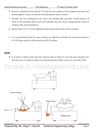
  • 5. Erbil Polytechnic University Soil Mechanics 3rd Stage /Civil Eng. Dept. Prepared by: Mr. Diyar I. Karash Technical Engineering College Page 5 PROCEDURE 1. Calibrate the height of fall of the liquid limit device it will use for a fall exactly 1 cm (not over ± 0.1mm) as shown in figure (2.a). Use 1 cm calibration block for making the adjustment. 2. Take about 250 g of air dried soil passing No.40 (425 µm) sieve and place it in a porcelain mixing dish, add a small amount of water and carefully mix the soil by using spatula to form a uniform paste. 3. Place a portion of the paste in the brass cup of liquid limit device and level it off to a maximum depth of about 1 cm, then the surface of the paste should be smoothed off level and parallel to the base as shown in figure (2. a). 4. Draw the grooving tool from back to front through the sample along the symmetrical axis of the cup with a circular motion keeping the tool normal to the cup surface as shown in figure (2. a). 5. Turn the crank handle at a rate of 2 rps (revolution per second) so that the brass cup is lifted and dropped. Record the number of blows N required closing the groove along a distance of 13 mm as shown in figure (2. b).
  • 6. Erbil Polytechnic University Soil Mechanics 3rd Stage /Civil Eng. Dept. Prepared by: Mr. Diyar I. Karash Technical Engineering College Page 6 6. Remove a quantity of soil (about 10-15 g) from the portions of the sample that have just flowed together, which is used for determining the water content. 7. Transfer the soil remaining in the cup to the mixing dish, and add a small amount of water to the porcelain dish of soil and carefully mix the soil by using spatula to form a uniform color and consistency. 8. Repeat step 3 to 7 for three additional specimens with various water content.  It is recommended that the water content be adjusted to obtain two specimens between (15-25) blows and two others between (25-35) blows. NOTE:  It is easier to blend water into the mixture than to blend in new soil mass becomes too wet and must be dried to obtain the desired spread of blow counts on each side of 25. 1 3 2 About 1 cm Groove motion Hand crank Rubber base
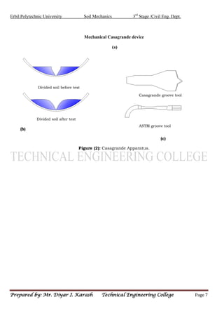
  • 7. Erbil Polytechnic University Soil Mechanics 3rd Stage /Civil Eng. Dept. Prepared by: Mr. Diyar I. Karash Technical Engineering College Page 7 Mechanical Casagrande device (a) (b) (c) (b) (c) Figure (2): Casagrande Apparatus. Casagrande groove tool ASTM groove tool Divided soil after test Divided soil before test
  • 8. Erbil Polytechnic University Soil Mechanics 3rd Stage /Civil Eng. Dept. Prepared by: Mr. Diyar I. Karash Technical Engineering College Page 8
  • 9. Erbil Polytechnic University Soil Mechanics 3rd Stage /Civil Eng. Dept. Prepared by: Mr. Diyar I. Karash Technical Engineering College Page 9 CALCULATION i. Calculate the water content for each blow account as in the water content test. ii. Using semi-logarithmic chart plot the water content (w.c.] as [linear scale] against the corresponding number of blows (N) as [Log- scale]. iii. Draw the best straight line fitting the plotted points. This is called the “Flow Curve”. iv. Draw the ordinate representing 25 blows and where it intersects the flow curve draw the horizontal line to the water content axis. Read off this value of water content which is equal to [Liquid Limit] of the soil. v. Use equation L.L = w.c (N/25)0.121 And compute the liquid limit for each value of N and w.c. Tabulate in your "Discussion" and make a comparison with L.L from the semi-log plot. DISCUSSION 1- Why we use Atterberg limits to characterize fine-grained soil? 2- The liquid limit cannot be more than 100%. It is true or not? Explain. 3- Where shrinkage limit is useful to be known?
  • 10. Erbil Polytechnic University Soil Mechanics 3rd Stage /Civil Eng. Dept. Prepared by: Mr. Diyar I. Karash Technical Engineering College Page 10 2- PLASTIC LIMIT TEST DEFINITION The plastic limit test is used to determine the lowest moisture content at which the soil behaves plastically. METHODS OF DETERMINING PLASTIC LIMIT The following methods can be applied to determine the plastic limit:- 1- CONE PENETROMETER METHOD 2- CONVENTION PLASTIC LIMIT TEST DEFINITION It is the popular test and is usually performed in conjunction with the liquid limit test. It is defined as the water content at which the soil begins to crumble when it can be rolled into a thread of approximately 3 mm in diameter. APPARATUS 1. Smooth glass surface for rolling the thread. 2. Container for determination of water content. 3. Balance sensitive to 0.01g. 4. Oven.
  • 11. Erbil Polytechnic University Soil Mechanics 3rd Stage /Civil Eng. Dept. Prepared by: Mr. Diyar I. Karash Technical Engineering College Page 11 PROCEDURE 1. Take about 20g of plastic soil (set aside earlier during the preparation for liquid limit). 2. The soil is kneaded into several smaller samples, shaped into (1-2) cm diameter ball. The material should be plastic enough not to stick to the fingers when squeeze. 3. Roll the soil between fingers on a glass plate to form a uniform thread of 3 mm diameter (The rate of rolling should be a bout 80-90 strokes per minute, counting one stroke when the hand moves forward and backward to the starting point). 4. If the diameter of the thread becomes less than 3 mm without cracks, it shows that the water content is more than the plastic limit. Knead the soil to reduce the water content, and roll it again to thread. 5. Repeat the process of alternate rolling and kneading until the thread crumbles and the soil can no longer be rolled into thread. 6. Collect the pieces of the crumbled soil thread in a moisture content container, and determine its water content. 7. Repeat the procedure at least twice more with fresh samples of plastic soil each time.
  • 12. Erbil Polytechnic University Soil Mechanics 3rd Stage /Civil Eng. Dept. Prepared by: Mr. Diyar I. Karash Technical Engineering College Page 12 CALCULATION i. Determine the plastic limit, which is taken as the average of three values. ii. Compute the plasticity index (PI): PI = LL – PL DISCUSSION What is the effect of Plastic Limit on the properties of soils? Explain ATTERBERG LIMITS DATA SHEET Name: Class : ……… Group No.: ………… 1- Liquid Limit Test No Can No. Weight of can (g) Weight of can + wet soil (g) Weight of can + dry soil (g) Weight of dry soil (g) Weight of Moisture (g) Water content % Blow count
  • 13. Erbil Polytechnic University Soil Mechanics 3rd Stage /Civil Eng. Dept. Prepared by: Mr. Diyar I. Karash Technical Engineering College Page 13 2- Plastic Limit Test No Can No. Weight of can (g) Weight of can + wet soil (g) Weight of can + dry soil (g) Weight of dry soil (g) Weight of Moisture (g) Water content % Plasticity Index = LL – PL =