

![ANSYSWorkbench–SimulationANSYSWorkbench–Simulation
Training Manual
Thermal Analysis
August 26, 2005
Inventory #002265
6-3
Basics of Steady-State Heat Transfer
• For a steady-state (static) thermal analysis in Simulation,
the temperatures {T} are solved for in the matrix below:
Assumptions:
– No transient effects are considered in a steady-state analysis
– [K] can be constant or a function of temperature
– {Q} can be constant or a function of temperature
( )[ ]{ } ( ){ }TQTTK =](https://image.slidesharecdn.com/aws100ch06thermal-190722061730/85/Aws100-ch06-thermal-3-320.jpg)
![ANSYSWorkbench–SimulationANSYSWorkbench–Simulation
Training Manual
Thermal Analysis
August 26, 2005
Inventory #002265
6-4
Basics of Steady-State Heat Transfer
• Fourier’s Law provides the basis of the previous equation:
• Heat flow within a solid (Fourier’s Law) is the basis of [K]
• Heat flux, heat flow rate, and convection are treated as boundary
conditions on the system {Q}
• Convection is treated as a boundary condition although
temperature-dependent film coefficients are possible
• It is important to remember these assumptions related to
performing thermal analyses in Simulation.](https://image.slidesharecdn.com/aws100ch06thermal-190722061730/85/Aws100-ch06-thermal-4-320.jpg)


Aws100 ch06 thermal
- 2. ANSYSWorkbench–SimulationANSYSWorkbench–Simulation Training Manual Thermal Analysis August 26, 2005 Inventory #002265 6-2 Chapter Overview • In this chapter, performing steady-state and transient thermal analyses in Simulation will be covered: A. Geometry B. Assemblies – Solid Body Contact C. Heat Loads D. Solution Options E. Results and Postprocessing F. Workshop 6.1 G. Thermal Transient Setup H. Transient Settings I. Transient Loads J. Transient Results K. Workshop 6.2 • The capabilities described in this section are generally applicable to ANSYS DesignSpace Entra licenses and above, except for an ANSYS Structural license.
- 3. ANSYSWorkbench–SimulationANSYSWorkbench–Simulation Training Manual Thermal Analysis August 26, 2005 Inventory #002265 6-3 Basics of Steady-State Heat Transfer • For a steady-state (static) thermal analysis in Simulation, the temperatures {T} are solved for in the matrix below: Assumptions: – No transient effects are considered in a steady-state analysis – [K] can be constant or a function of temperature – {Q} can be constant or a function of temperature ( )[ ]{ } ( ){ }TQTTK =
- 4. ANSYSWorkbench–SimulationANSYSWorkbench–Simulation Training Manual Thermal Analysis August 26, 2005 Inventory #002265 6-4 Basics of Steady-State Heat Transfer • Fourier’s Law provides the basis of the previous equation: • Heat flow within a solid (Fourier’s Law) is the basis of [K] • Heat flux, heat flow rate, and convection are treated as boundary conditions on the system {Q} • Convection is treated as a boundary condition although temperature-dependent film coefficients are possible • It is important to remember these assumptions related to performing thermal analyses in Simulation.
- 5. ANSYSWorkbench–SimulationANSYSWorkbench–Simulation Training Manual Thermal Analysis August 26, 2005 Inventory #002265 6-5 Physics Filters • If a thermal-only solution is to be performed the Physics Filter can be used to filter the GUI – Under “View menu > Physics Filter,” unselect the “Structural” and “Electromagnetic” options – This applies to options in the “Environment” and “Solution” levels only – If a thermal-stress simulation is to be performed, do not turn off the structural physics filter ANSYS License Availability DesignSpace Entra x DesignSpace x Professional x Structural Mechanical/Multiphysics x
- 6. ANSYSWorkbench–SimulationANSYSWorkbench–Simulation Training Manual Thermal Analysis August 26, 2005 Inventory #002265 6-6 A. Geometry • In thermal analyses, all types of bodies supported by Simulation may be used. – Solid, surface, and line bodies are supported – For surface bodies, thickness must be input in the Details view of the Geometry branch – Line bodie cross-section and orientation is defined within DesignModeler – Cross-section and orientation information results in an ‘effective’ thermal cross-section – Only temperature results are available for line bodies – The “Point Mass” feature is not available in thermal analyses ANSYS License Availability DesignSpace Entra x DesignSpace x Professional x Structural Mechanical/Multiphysics x
- 7. ANSYSWorkbench–SimulationANSYSWorkbench–Simulation Training Manual Thermal Analysis August 26, 2005 Inventory #002265 6-7 … Geometry • Shell and line body assumptions: – For shell bodies through-thickness temperature gradients are not available. Shells assume temperatures on top and bottom of surface are the same – For line bodies through thickness variation in the temperature is not available. Line bodies assume the temperature is constant across the cross-section • Temperature variation will still be considered along the line body ANSYS License Availability DesignSpace Entra x DesignSpace x Professional x Structural Mechanical/Multiphysics x
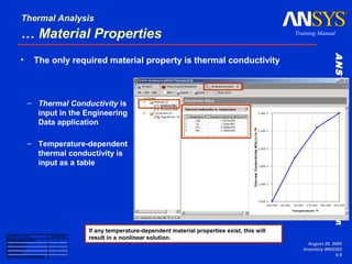
- 8. ANSYSWorkbench–SimulationANSYSWorkbench–Simulation Training Manual Thermal Analysis August 26, 2005 Inventory #002265 6-8 … Material Properties – Thermal Conductivity is input in the Engineering Data application – Temperature-dependent thermal conductivity is input as a table ANSYS License Availability DesignSpace Entra x DesignSpace x Professional x Structural Mechanical/Multiphysics x If any temperature-dependent material properties exist, this will result in a nonlinear solution. • The only required material property is thermal conductivity
- 9. ANSYSWorkbench–SimulationANSYSWorkbench–Simulation Training Manual Thermal Analysis August 26, 2005 Inventory #002265 6-9 B. Assemblies – Solid Body Contact • When importing assemblies of solid parts, contact regions are automatically created between the solid bodies enabling heat transfer between parts in an assembly Model shown is from a sample Inventor assembly. ANSYS License Availability DesignSpace Entra DesignSpace x Professional x Structural Mechanical/Multiphysics x
- 10. ANSYSWorkbench–SimulationANSYSWorkbench–Simulation Training Manual Thermal Analysis August 26, 2005 Inventory #002265 6-10 … Assemblies – Contact Region – No heat spreading is considered in the contact/target interface • Heat flow within the contact region is in the contact normal direction only • Heat flows only if a target element is present in the normal direction of a contact element In the figure on the left, the solid green double-arrows indicate heat flow within the contact region. Heat flow only occurs if a target surface is normal to a contact surface. The light, dotted green arrows indicate that no heat transfer will occur between parts. ANSYS License Availability DesignSpace Entra DesignSpace x Professional x Structural Mechanical/Multiphysics x
- 11. ANSYSWorkbench–SimulationANSYSWorkbench–Simulation Training Manual Thermal Analysis August 26, 2005 Inventory #002265 6-11 … Assemblies – Contact Region – If the parts are initially in contact heat transfer will occur between the parts. – If the parts are initially out of contact no heat transfer takes place – Summary: – The pinball region determines when contact occurs and is automatically defined and set to a relatively small value to accommodate small gaps in the model Initially Touching Inside Pinball Region Outside Pinball Region Bonded Yes Yes No No Separation Yes Yes No Rough Yes No No Frictionless Yes No No Contact Type Heat Transfer Between Parts in Contact Region? ANSYS License Availability DesignSpace Entra DesignSpace x Professional x Structural Mechanical/Multiphysics x
- 12. ANSYSWorkbench–SimulationANSYSWorkbench–Simulation Training Manual Thermal Analysis August 26, 2005 Inventory #002265 6-12 … Assemblies – Contact Region • If the contact is bonded or no separation, then heat transfer will occur (solid green lines) when the surfaces are within the pinball radius In this figure on the right, the gap between the two parts is bigger than the pinball region, so no heat transfer will occur between the parts Pinball Radius ANSYS License Availability DesignSpace Entra DesignSpace Professional x Structural Mechanical/Multiphysics x
- 13. ANSYSWorkbench–SimulationANSYSWorkbench–Simulation Training Manual Thermal Analysis August 26, 2005 Inventory #002265 6-13 … Assemblies – Thermal Conductance – The amount of heat flow between two parts is defined by the contact heat flux q: – where Tcontact is the temperature of a contact “node” and Ttarget is the temperature of the corresponding target “node” – By default, TCC is set to a relatively ‘high’ value based on the largest material conductivity defined in the model KXX and the diagonal of the overall geometry bounding box ASMDIAG. – This essentially provides ‘perfect’ conductance between parts. ( )contacttarget TTTCCq −⋅= ASMDIAGKXXTCC /000,10⋅= ANSYS License Availability DesignSpace Entra DesignSpace x Professional x Structural Mechanical/Multiphysics x
- 14. ANSYSWorkbench–SimulationANSYSWorkbench–Simulation Training Manual Thermal Analysis August 26, 2005 Inventory #002265 6-14 … Assemblies – Thermal Conductance • Perfect thermal contact conductance between parts means that no temperature drop is assumed at the interface • One may want to include finite thermal conductance instead – The contact conductance can be influenced by many factors: • surface flatness • surface finish • oxides • entrapped fluids • contact pressure • surface temperature • use of conductive grease ∆T T x
- 15. ANSYSWorkbench–SimulationANSYSWorkbench–Simulation Training Manual Thermal Analysis August 26, 2005 Inventory #002265 6-15 … Assemblies – Thermal Conductance • In ANSYS Professional licenses and above, the user may define a finite thermal contact conductance (TCC) if the Pure Penalty or Augmented Lagrange Formulation is used – The thermal contact conductance per unit area is input for each contact region in the Details view – If thermal contact resistance is known invert this value and divide by the contacting area to obtain TCC value If “Thermal Conductance” is left at “Program Chosen,” near- perfect thermal contact conductance will be defined. thermal contact conductance can be input which is the same as including thermal contact resistance at a contact interface. ANSYS License Availability DesignSpace Entra DesignSpace Professional x Structural Mechanical/Multiphysics x
- 16. ANSYSWorkbench–SimulationANSYSWorkbench–Simulation Training Manual Thermal Analysis August 26, 2005 Inventory #002265 6-16 … Assemblies – Thermal Conductance • Thermal Contact Notes: – For symmetric contact the user does not need to account for a ‘double’ thermal contact resistance – MPC bonded contact allows for perfect thermal contact conductance ANSYS License Availability DesignSpace Entra DesignSpace Professional x Structural Mechanical/Multiphysics x
- 17. ANSYSWorkbench–SimulationANSYSWorkbench–Simulation Training Manual Thermal Analysis August 26, 2005 Inventory #002265 6-17 … Assemblies – Surface Body Contact • Edge contact is a subset of general contact: – For contact including shell faces or solid edges only bonded or no separation behavior is allowed – For contact involving shell edges only bonded behavior using MPC formulation is allowed: • The user can set the search direction as either the target normal or pinball region. • If a gap exists the pinball region can be used for the search direction to detect contact beyond a gap ANSYS License Availability DesignSpace Entra DesignSpace Professional x Structural Mechanical/Multiphysics x
- 18. ANSYSWorkbench–SimulationANSYSWorkbench–Simulation Training Manual Thermal Analysis August 26, 2005 Inventory #002265 6-18 … Assemblies – Spot Weld • Spot welds provide discreet heat transfer points: – Spotweld definition is done in the CAD software (currently only DesignModeler and Unigraphics) – Spotwelds can be created in Simulation manually at vertices ANSYS License Availability DesignSpace Entra DesignSpace x Professional x Structural Mechanical/Multiphysics x DesignModeler x Pro/ENGINEER Unigraphics x SolidWorks Inventor Solid Edge Mechanical Desktop CATIA V4 CATIA V5 ACIS (SAT) Parasolid IGES
- 19. ANSYSWorkbench–SimulationANSYSWorkbench–Simulation Training Manual Thermal Analysis August 26, 2005 Inventory #002265 6-19 C. Heat Loads • Heat Flow: – A heat flow rate can be applied to a vertex, edge, or surface. The load gets distributed for multiple selections – Heat flow has units of energy/time • Heat Flux: – A heat flux can be applied to surfaces only – Heat flux has units of energy/time/area • Internal Heat Generation: – An internal heat generation rate can be applied to bodies only. – Heat generation has units of energy/time/volume A positive value for heat load will add energy to the system. ANSYS License Availability DesignSpace Entra x DesignSpace x Professional x Structural Mechanical/Multiphysics x
- 20. ANSYSWorkbench–SimulationANSYSWorkbench–Simulation Training Manual Thermal Analysis August 26, 2005 Inventory #002265 6-20 … Adiabatic Conditions • Perfectly Insulated: – Perfectly insulated condition is applied to surfaces – This is the default condition in thermal analyses when no load is applied: • This load type is used as a way to remove loading on specified surfaces • For example, it may be easier for a user to apply heat flux or convection on an entire part, then use the perfectly insulated condition to selectively ‘remove’ the loading on some surfaces ANSYS License Availability DesignSpace Entra x DesignSpace x Professional x Structural Mechanical/Multiphysics x
- 21. ANSYSWorkbench–SimulationANSYSWorkbench–Simulation Training Manual Thermal Analysis August 26, 2005 Inventory #002265 6-21 … Thermal Boundary Conditions Temperature, Convection and Radiation: • At least one type of thermal boundary condition must be present to prevent the thermal equivalent of rigid body motion • Given Temperature or Convection load should not be applied on surfaces that already have another heat load or thermal boundary condition applied to it – Perfect insulation will override thermal boundary conditions • Given Temperature: – Imposes a temperature on vertices, edges, surfaces or bodies – Temperature is the degree of freedom solved for ANSYS License Availability DesignSpace Entra x DesignSpace x Professional x Structural Mechanical/Multiphysics x
- 22. ANSYSWorkbench–SimulationANSYSWorkbench–Simulation Training Manual Thermal Analysis August 26, 2005 Inventory #002265 6-22 … Thermal Boundary Conditions • Convection: – Applied to surfaces only (edges in 2D analyses) – Convection q is related to a film coefficient h, the surface area A, and the difference in the surface temperature Tsurface & ambient temperature Tbulk – “h” and “Tbulk” are user-input values – The film coefficient h can be constant or temperature dependent ( )ambientsurface TThAq −= ANSYS License Availability DesignSpace Entra x DesignSpace x Professional x Structural Mechanical/Multiphysics x
- 23. ANSYSWorkbench–SimulationANSYSWorkbench–Simulation Training Manual Thermal Analysis August 26, 2005 Inventory #002265 6-23 … Thermal Boundary Conditions • Temperature-Dependent Convection: – Select “New Convection…” for the Correlation – The “Engineering Data” tab will open and the Coefficient Type can then be defined for the convection load – Determine what temperature is used for h(T): • Average film temperature T=(Tsurface+Tbulk)/2 • Surface temperature T= Tsurface • Bulk temperature T= Tbulk • Difference of surface and bulk temperatures T=(Tsurface-Tbulk) ANSYS License Availability DesignSpace Entra x DesignSpace x Professional x Structural Mechanical/Multiphysics x Select the temperature- dependency from the pull-down menu
- 24. ANSYSWorkbench–SimulationANSYSWorkbench–Simulation Training Manual Thermal Analysis August 26, 2005 Inventory #002265 6-24 … Thermal Boundary Conditions • Temperature-Dependent Convection (continued): • The user inputs the film coefficients and temperatures in a table. The values are plotted on a graph, as shown below ANSYS License Availability DesignSpace Entra x DesignSpace x Professional x Structural Mechanical/Multiphysics x Temperature-dependent convection will result in a nonlinear solution. The only exception is if the film coefficient h is based on a function of the bulk temperature only. Right mouse click on the table to add or delete values.
- 25. ANSYSWorkbench–SimulationANSYSWorkbench–Simulation Training Manual Thermal Analysis August 26, 2005 Inventory #002265 6-25 … Thermal Boundary Conditions • Temperature-Dependent Convection (continued): • The convection data can also be imported from a file ANSYS License Availability DesignSpace Entra x DesignSpace x Professional x Structural Mechanical/Multiphysics x
- 26. ANSYSWorkbench–SimulationANSYSWorkbench–Simulation Training Manual Thermal Analysis August 26, 2005 Inventory #002265 6-26 … Thermal Boundary Conditions • Radiation: – Applied to surfaces (edges in 2D analyses) – Where: • σ = Stefan-Boltzman constant • ε = Emmisivity • A = Area of radiating surface • F = Form factor (1) – Provides for radiation to ambient only (not between surfaces) – Form factor assumed to be 1 – Stefan Boltzman constant is determined and set automatically based on the active working unit system ( )44 ambientsurfaceR TTFAQ −=σε
- 27. ANSYSWorkbench–SimulationANSYSWorkbench–Simulation Training Manual Thermal Analysis August 26, 2005 Inventory #002265 6-27 D. Solution Options • Solution options are set under the “Solutions” branch: – The ANSYS database can be saved – Two solvers are available in Simulation: • Default = Program Chosen – Iterative = PCG solver – Direct = sparse solver – The “Weak Springs” and “Large Deflection” options are meant for structural analyses only, so they can be ignored for a thermal analysis ANSYS License Availability DesignSpace Entra x DesignSpace x Professional x Structural Mechanical/Multiphysics x
- 28. ANSYSWorkbench–SimulationANSYSWorkbench–Simulation Training Manual Thermal Analysis August 26, 2005 Inventory #002265 6-28 … Solution Options • Informative settings show the user the status of the analysis: – “Analysis Type” – Nonlinear solution – Solver working directory – Any solver messages which appear after solution can be checked afterwards under “Solver Messages” ANSYS License Availability DesignSpace Entra x DesignSpace x Professional x Structural Mechanical/Multiphysics x
- 29. ANSYSWorkbench–SimulationANSYSWorkbench–Simulation Training Manual Thermal Analysis August 26, 2005 Inventory #002265 6-29 … Solving the Model • To solve the model, request results and “Solve” – If a “Solution Information” branch is requested, the details of the solution output can be examined ANSYS License Availability DesignSpace Entra x DesignSpace x Professional x Structural Mechanical/Multiphysics x
- 30. ANSYSWorkbench–SimulationANSYSWorkbench–Simulation Training Manual Thermal Analysis August 26, 2005 Inventory #002265 6-30 … Solving the Model • To perform a thermal-stress solution add structural supports and/or loads and request structural results, then solve the model – The following will be performed automatically: • A steady-state thermal analysis will be performed • The temperature field will be mapped back onto the structural model • A structural analysis will be performed – Simulation automates this type of coupled-field solution ANSYS License Availability DesignSpace Entra x DesignSpace x Professional x Structural Mechanical/Multiphysics x
- 31. ANSYSWorkbench–SimulationANSYSWorkbench–Simulation Training Manual Thermal Analysis August 26, 2005 Inventory #002265 6-31 E. Results and Postprocessing • Various results are available for postprocessing: – Temperature – Heat Flux – “Reaction” Heat Flow Rate • In Simulation, results are usually requested before solving, but they can be requested afterwards, too. – A new solution is not required for retrieving output of a solved model.
- 32. ANSYSWorkbench–SimulationANSYSWorkbench–Simulation Training Manual Thermal Analysis August 26, 2005 Inventory #002265 6-32 … Temperature • Temperature: – Temperature is a scalar quantity and has no direction associated with it. ANSYS License Availability DesignSpace Entra x DesignSpace x Professional x Structural Mechanical/Multiphysics x
- 33. ANSYSWorkbench–SimulationANSYSWorkbench–Simulation Training Manual Thermal Analysis August 26, 2005 Inventory #002265 6-33 … Heat Flux • Heat flux contour or vector plots are available: – Heat flux q is defined as – “Total Heat Flux” and “Directional Heat Flux” can be requested • The magnitude & direction can be plotted as vectors by activating vector mode TKXXq ∇⋅−= ANSYS License Availability DesignSpace Entra x DesignSpace x Professional x Structural Mechanical/Multiphysics x
- 34. ANSYSWorkbench–SimulationANSYSWorkbench–Simulation Training Manual Thermal Analysis August 26, 2005 Inventory #002265 6-34 … Reaction Heat Flow Rate • Reaction heat flow rates is available for Given Temperature or Convection boundary conditions: – Reaction heat flow rate is printed in the Details view after a solution. ANSYS License Availability DesignSpace Entra x DesignSpace x Professional x Structural Mechanical/Multiphysics x
- 35. ANSYSWorkbench–SimulationANSYSWorkbench–Simulation Training Manual Thermal Analysis August 26, 2005 Inventory #002265 6-35 … Reaction Heat Flow Rate • The “Worksheet” tab for the “Environment” branch has a tabular summary of reaction heat flow rates – Note: if a thermal support shares a vertex, edge, or surface with another thermal support or load the reported reaction heat flow rate may be incorrect. The solution will still be valid, but the reported values may not be accurate ANSYS License Availability DesignSpace Entra x DesignSpace x Professional x Structural Mechanical/Multiphysics x
- 36. ANSYSWorkbench–SimulationANSYSWorkbench–Simulation Training Manual Thermal Analysis August 26, 2005 Inventory #002265 6-36 F. Workshop 6.1 – Steady State Thermal Analysis • Workshop 6.1 – Steady State Thermal Analysis • Goal: – Analyze the pump housing shown below for its heat transfer characteristics.
- 37. ANSYSWorkbench–SimulationANSYSWorkbench–Simulation Training Manual Thermal Analysis August 26, 2005 Inventory #002265 6-37 Transient Thermal Analysis • The previous discussion related to steady state analyses only. The following section introduces the ability to apply time dependent boundary conditions on thermal models • The previous sections are equally applicable in steady state or transient analyses • Three additional areas will be addressed concerning transient analysis: – Input time dependent boundary conditions – Set up transient solution options – Access results over time
- 38. ANSYSWorkbench–SimulationANSYSWorkbench–Simulation Training Manual Thermal Analysis August 26, 2005 Inventory #002265 6-38 G: Thermal Transient Setup • A thermal transient analysis is specified from the Environment branch • An “End Time” must then be entered to indicate the duration of the analysis • Supported transient loads: – Temperature – Heat flux – Heat generation rate – Heat flow – Convection film coefficient – Ambient temperature for radiation or convection
- 39. ANSYSWorkbench–SimulationANSYSWorkbench–Simulation Training Manual Thermal Analysis August 26, 2005 Inventory #002265 6-39 . . . Thermal Transient Setup • When a transient analysis is requested the GUI will update with new information sections: – Environment will contain an “Initial Condition” branch – Solution will contain a “Transient Settings” branch – A timeline and table will be inserted below the graphics screen
- 40. ANSYSWorkbench–SimulationANSYSWorkbench–Simulation Training Manual Thermal Analysis August 26, 2005 Inventory #002265 6-40 . . . Initial Conditions • Initial conditions can be handled in 2 ways: – Uniform specified temperature – Non uniform temperature distribution based on a previously solved Environment • Choose the steady state result to be used as an initial condition then, RMB > “Generate Transient Environment with Initial Condition”
- 41. ANSYSWorkbench–SimulationANSYSWorkbench–Simulation Training Manual Thermal Analysis August 26, 2005 Inventory #002265 6-41 H. Transient Settings • Transient settings and details: The next several pages contain descriptions of individual areas
- 42. ANSYSWorkbench–SimulationANSYSWorkbench–Simulation Training Manual Thermal Analysis August 26, 2005 Inventory #002265 6-42 . . . Transient Settings • Transient Details: – Time stepping controls – Visibility of transient information DT (Delta Time) Legend Chart Legend Tabular Data Curve Type Column
- 43. ANSYSWorkbench–SimulationANSYSWorkbench–Simulation Training Manual Thermal Analysis August 26, 2005 Inventory #002265 6-43 . . . Transient Settings • Automatic Step Resets: – Automatic time step reset places resets at extreme inflection points in the load history • The slider controls the reset frequency – Manual resets can be added by RMB in the transient settings graph and at the desired time point • Manual reset points can be moved by dragging with the cursor Move reset point
- 44. ANSYSWorkbench–SimulationANSYSWorkbench–Simulation Training Manual Thermal Analysis August 26, 2005 Inventory #002265 6-44 . . . Transient Settings • Time reset points are indicated by the triangular markers at the top of the chart – Automatic resets: solid – Manual resets: wire frame
- 45. ANSYSWorkbench–SimulationANSYSWorkbench–Simulation Training Manual Thermal Analysis August 26, 2005 Inventory #002265 6-45 . . . Transient Settings • The “visible” column in the time line legend controls specific information to be plotted – Notice here the heat flux is applied as a step function with solution resets at each inflection point Heat flux history Time step reset points
- 46. ANSYSWorkbench–SimulationANSYSWorkbench–Simulation Training Manual Thermal Analysis August 26, 2005 Inventory #002265 6-46 I. Transient Loads • Transient loads are applied using the same techniques discussed earlier. The only difference will be the setup in the details for the load • Instead of choosing “Constant” (default), choose “Load History” • The history data can be imported from a previously saved file or created using the Engineering Data application
- 47. ANSYSWorkbench–SimulationANSYSWorkbench–Simulation Training Manual Thermal Analysis August 26, 2005 Inventory #002265 6-47 . . . Transient Loads • After choosing “New Load History”, time and load data is entered in the Engineering Data application • The plot builds as the data is entered • Project load histories are managed the same way as materials and convections
- 48. ANSYSWorkbench–SimulationANSYSWorkbench–Simulation Training Manual Thermal Analysis August 26, 2005 Inventory #002265 6-48 J. Transient Results • Transient results are plotted like steady state, by highlighting the branch, however additional information and controls are available The details view and graphics legend include the “display time” Timeline and tabular data are available for each result time solved for Check boxes control timeline display
- 49. ANSYSWorkbench–SimulationANSYSWorkbench–Simulation Training Manual Thermal Analysis August 26, 2005 Inventory #002265 6-49 . . . Transient Results • To view results from different time points: – Click on the time point of interest in the timeline – The details will indicate a red background until the results are retrieved for the selected time point – To complete the operation, in the timeline “RMB > Retrieve Results” Results not updated New time point selected
- 50. ANSYSWorkbench–SimulationANSYSWorkbench–Simulation Training Manual Thermal Analysis August 26, 2005 Inventory #002265 6-50 . . . Transient Results • Transient animations are controlled using the same controller as steady state animations • To animate a specific range use the mouse to drag over the desired times • The resulting animation will span the highlighted region
- 51. ANSYSWorkbench–SimulationANSYSWorkbench–Simulation Training Manual Thermal Analysis August 26, 2005 Inventory #002265 6-51 K. Workshop 6.2 – Transient Thermal Analysis • Workshop 6.2 – Transient Thermal Analysis • Goal: – Analyze the heating base on a steam iron like the ones shown here for steady state and cyclic loading conditions