SlideShare a Scribd company logo
ME 1222
APPLIED MECHANICS
DISTRIBUTED FORCES: CENTROIDS
AND CENTERS OF GRAVITY
Department of Mechanical Engineering, General Sir John Kotelawala Defence University
CHAPTER 05
COURSE OUTLINE
Department of Mechanical Engineering, General Sir John Kotelawala Defence University
1. Introduction
2. Statics of Objects
3. Rigid Bodies: Equivalent System of Forces
4. Equilibrium of Rigid Bodies
5. Distributed Forces: Centre of Gravity
6. Friction
7. Introduction to Vibration
3
CONTENT
3
CHAPTER 5 – Distributed Forces: Centroids and Centers of Gravity
1. Introduction
2. Center of Gravity of a 2D Body
3. Centroids and First Moments of Areas and Lines
4. Centroids of Common Shapes of Areas
5. Centroids of Common Shapes of Lines
6. Composite Plates and Areas
7. Determination of Centroids by Integration
8. Theorems of Pappus-Guldinus
9. Distributed Loads on Beams
10. Center of Gravity of a 3D Body: Centroid of a Volume
11. Centroids of Common 3D Shapes
12. Composite 3D Bodies
Department of Mechanical Engineering, General Sir John Kotelawala Defence University 5
1. INTRODUCTION
•The earth exerts a gravitational force on each of the particles forming a
body.
•These forces can be replaced by a single equivalent force equal to the
weight of the body and applied at the center of gravity for the body.
•The centroid of an area is analogous to the center of gravity of a body.
The concept of the first moment of an area is used to locate the centroid.
•Determination of the area of a surface of revolution and the volume of a
body of revolution are accomplished with the Theorems of Pappus-
Guldinus.
Department of Mechanical Engineering, General Sir John Kotelawala Defence University 6
2. CENTER OF GRAVITY OF A 2D BODY
• Center of Gravity of a Plate
σ 𝑀𝑥 : ത
𝑦𝑊= 𝑦1∆𝑊1 + 𝑦2∆𝑊2 + … . . +𝑦𝑛∆𝑊
𝑛
σ 𝑀𝑦 : ҧ
𝑥𝑊= 𝑥1∆𝑊1 + 𝑥2∆𝑊2 + … . . +𝑥𝑛∆𝑊
𝑛
Taking moments of W about the y and x axes:
ҧ
𝑥 =
𝑥1∆𝑊1 + 𝑥2∆𝑊2+ . . . +𝑥𝑛∆𝑊
𝑛
𝑊
ത
𝑦 =
𝑦1∆𝑊1 + 𝑦2∆𝑊2+ . . . +𝑦𝑛∆𝑊
𝑛
𝑊
Solving equations:
𝑾 = න 𝒅𝑾 ഥ
𝒙 =
‫׬‬ 𝒙 𝒅𝑾
𝑾
ഥ
𝒚 =
‫׬‬ 𝒚 𝒅𝑾
𝑾
Department of Mechanical Engineering, General Sir John Kotelawala Defence University 7
2. CENTER OF GRAVITY OF A 2D BODY
• Center of Gravity of a Wire
Contd..
σ 𝑀𝑥 : ത
𝑦𝑊= 𝑦1∆𝑊1 + 𝑦2∆𝑊2 + … . . +𝑦𝑛∆𝑊
𝑛
σ 𝑀𝑦 : ҧ
𝑥𝑊= 𝑥1∆𝑊1 + 𝑥2∆𝑊2 + … . . +𝑥𝑛∆𝑊
𝑛
Taking moments of W about the y and x axes:
ҧ
𝑥 =
𝑥1∆𝑊1 + 𝑥2∆𝑊2+ . . . +𝑥𝑛∆𝑊
𝑛
𝑊
ത
𝑦 =
𝑦1∆𝑊1 + 𝑦2∆𝑊2+ . . . +𝑦𝑛∆𝑊
𝑛
𝑊
Solving equations:
𝑾 = න 𝒅𝑾 ഥ
𝒙 =
‫׬‬ 𝒙 𝒅𝑾
𝑾
ഥ
𝒚 =
‫׬‬ 𝒚 𝒅𝑾
𝑾
Department of Mechanical Engineering, General Sir John Kotelawala Defence University 8
3. CENTROIDS AND FIRST MOMENTS OF AREAS AND LINES
• Centroid of an Area
Magnitude ΔW of the weight of an element of the plate
∆W= 𝛾𝑡∆𝐴
Similarly,
W= 𝛾𝑡𝐴
σ 𝑀𝑥 : ത
𝑦𝐴= 𝑦1∆𝐴1 + 𝑦2∆𝐴2 + … . . +𝑦𝑛∆𝐴𝑛
σ 𝑀𝑦 : ҧ
𝑥𝐴= 𝑥1∆𝐴1 + 𝑥2∆𝐴2 + … . . +𝑥𝑛∆𝐴𝑛
Substituting for ∆𝑊 and W in the moment equations and dividing
throughout by 𝛾𝑡,
ഥ
𝒙 =
‫׬‬ 𝒙 𝒅𝑨
𝑨
ഥ
𝒚 =
‫׬‬ 𝒚 𝒅𝑨
𝑨
Department of Mechanical Engineering, General Sir John Kotelawala Defence University 9
3. CENTROIDS AND FIRST MOMENTS OF AREAS AND LINES
• Centroid of a Line
Magnitude ΔW of the weight of an element of wire
∆𝑊 = 𝛾𝑎∆𝐿
ഥ
𝒙 =
‫׬‬ 𝒙 𝒅𝑳
𝑳
ഥ
𝒚 =
‫׬‬ 𝒚 𝒅𝑳
𝑳
Contd..
Department of Mechanical Engineering, General Sir John Kotelawala Defence University 10
4. FIRST MOMENTS OF AREAS AND LINES
• An area is symmetric with respect to an axis BB’ if for every
point P there exists a point P’ such that PP’ is perpendicular
to BB’ and is divided into two equal parts by BB’.
• The first moment of an area with respect to a line of
symmetry is zero.
• If an area possesses a line of symmetry, its centroid lies on
that axis.
• If an area possesses two lines of symmetry, its centroid lies
at their intersection.
• An area is symmetric with respect to a center O if for every
element dA at (x,y) there exists an equal area of dA’ at (-x,-y).
• The centroid of the area coincides with the center of
symmetry.
Department of Mechanical Engineering, General Sir John Kotelawala Defence University 11
5. CENTROIDS OF COMMON SHAPES OF AREAS
Department of Mechanical Engineering, General Sir John Kotelawala Defence University 12
5. CENTROIDS OF COMMON SHAPES OF AREAS Contd..
Department of Mechanical Engineering, General Sir John Kotelawala Defence University 13
6. CENTROIDS OF COMMON SHAPES OF LINES
Contd..
Department of Mechanical Engineering, General Sir John Kotelawala Defence University 14
7. COMPOSITE PLATES AND AREAS
• Composite Plates




=
=
W
y
W
Y
W
x
W
X
• Composite Area




=
=
A
y
A
Y
A
x
A
X
Department of Mechanical Engineering, General Sir John Kotelawala Defence University 15
SAMPLE PROBLEM 5.1
For the plane area shown,
(a) Determine the first moments with respect to the x and y axes and the
location of the centroid.
Department of Mechanical Engineering, General Sir John Kotelawala Defence University 16
SAMPLE PROBLEM 5.1
STRATEGY:
Break up the given area into simple components, find the centroid of each component, and
then find the overall first moments and centroid
MODELING:
Solution :
Contd..
Department of Mechanical Engineering, General Sir John Kotelawala Defence University 17
SAMPLE PROBLEM 5.1
ANALYSIS:
a. First Moments of the Area.
Find the total area and first moments of the triangle, rectangle, and
semicircle. Subtract the area and first moment of the circular cutout
3
3
3
3
mm
10
7
.
757
mm
10
2
.
506

+
=

+
=
y
x
Q
Q
b. Location of Centroid.
•Compute the coordinates of the area centroid by dividing the first
moments by the total area.
2
3
3
3
mm
10
13.828
mm
10
7
.
757


+
=
=


A
A
x
X
mm
8
.
54
=
X
2
3
3
3
mm
10
13.828
mm
10
2
.
506


+
=
=


A
A
y
Y
mm
6
.
36
=
Y
Contd..
( )
 
( )
 
dy
x
a
y
dA
y
A
y
dy
x
a
x
a
dA
x
A
x
el
el
−
=
=
−
+
=
=




2
Department of Mechanical Engineering, General Sir John Kotelawala Defence University 18
8. DETERMINATION OF CENTROIDS BY INTEGRATION






=
=
=
=
=
=
dA
y
dy
dx
y
dA
y
A
y
dA
x
dy
dx
x
dA
x
A
x
el
el • Double integration to find the first moment may
be avoided by defining dA as a thin rectangle or
strip.
( )
( )
ydx
y
dA
y
A
y
ydx
x
dA
x
A
x
el
el




=
=
=
=
2






=
=






=
=








d
r
r
dA
y
A
y
d
r
r
dA
x
A
x
el
el
2
2
2
1
sin
3
2
2
1
cos
3
2
Department of Mechanical Engineering, General Sir John Kotelawala Defence University 19
SAMPLE PROBLEM 5.4
Determine by direct integration the location of the centroid of a
parabolic spandrel.
Department of Mechanical Engineering, General Sir John Kotelawala Defence University 20
SAMPLE PROBLEM 5.4
2
1
2
1
2
2
2
2
2
y
b
a
x
or
x
a
b
y
a
b
k
a
k
b
x
k
y
=
=
=

=
=
Solution : STRATEGY:
First, express the parabolic curve using the parameters a and b. Then
choose a differential element of area and express its area in terms of a, b,
x, and y. We illustrate the solution first with a vertical element and then a
horizontal element.
MODELING:
a. Determination of the Constant k.
Contd..
Department of Mechanical Engineering, General Sir John Kotelawala Defence University 21
SAMPLE PROBLEM 5.4
• Choosing the differential element, the total area of the
region is,
3
3
0
3
2
0
2
2
ab
x
a
b
dx
x
a
b
dx
y
dA
A
a
a
=








=
=
=
=



Solution : ANALYSIS :
a. Vertical Differential Element
Contd..
Department of Mechanical Engineering, General Sir John Kotelawala Defence University 22
SAMPLE PROBLEM 5.4
• Using vertical strips, perform a single integration to find the first
moments.
10
5
2
2
1
2
4
4
2
0
5
4
2
0
2
2
2
2
0
4
2
0
2
2
ab
x
a
b
dx
x
a
b
dx
y
y
dA
y
Q
b
a
x
a
b
dx
x
a
b
x
dx
xy
dA
x
Q
a
a
el
x
a
a
el
y
=








=






=
=
=
=








=






=
=
=






Contd..
Department of Mechanical Engineering, General Sir John Kotelawala Defence University 23
SAMPLE PROBLEM 5.4
• Using horizontal strips, perform a single integration to find
the first moments.
( )
( )
10
4
2
1
2
2
2
0
2
3
2
1
2
1
2
1
2
0
2
2
0
2
2
ab
dy
y
b
a
ay
dy
y
b
a
a
y
dy
x
a
y
dA
y
Q
b
a
dy
y
b
a
a
dy
x
a
dy
x
a
x
a
dA
x
Q
b
el
x
b
b
el
y
=






−
=






−
=
−
=
=
=








−
=
−
=
−
+
=
=








b. Horizontal Differential Element.
Contd..
Department of Mechanical Engineering, General Sir John Kotelawala Defence University 24
SAMPLE PROBLEM 5.4
• Evaluate the centroid coordinates.
4
3
2
b
a
ab
x
Q
A
x y
=
=
a
x
4
3
=
10
3
2
ab
ab
y
Q
A
y x
=
=
b
y
10
3
=
Contd..
Department of Mechanical Engineering, General Sir John Kotelawala Defence University 25
9. THEOREMS OF PAPPUS-GULDINUS
• Area of a surface of revolution is equal to the length
of the generating curve times the distance traveled
by the centroid through the rotation.
L
y
A 
2
=
• Surface of revolution is generated by rotating a plane curve about a fixed axis.
Theorem 01
Department of Mechanical Engineering, General Sir John Kotelawala Defence University 26
9. THEOREMS OF PAPPUS-GULDINUS
• Volume of a body of revolution is equal to the
generating area times the distance traveled by
the centroid through the rotation.
A
y
V 
2
=
• Body of the revolution is generated by rotating a plane area about a fixed axis.
Theorem 02
Department of Mechanical Engineering, General Sir John Kotelawala Defence University 27
SAMPLE PROBLEM 5.7
The outside diameter of a pulley is 0.8 m, and the cross-section of its rim is as shown.
Knowing that the pulley is made of steel and that the density of steel is
Determine the mass and weight of the rim.
3
3
m
kg
10
85
.
7 
=

Department of Mechanical Engineering, General Sir John Kotelawala Defence University 28
SAMPLE PROBLEM 5.7
• Apply the theorem of Pappus-Guldinus to evaluate the volumes or
revolution for the rectangular rim section and the inner cutout
section.
• Multiply by density and acceleration to get the mass and
acceleration.
( )( ) 







=
= − 3
3
9
3
6
3
3
mm
m
10
mm
10
65
.
7
m
kg
10
85
.
7
V
m  kg
0
.
60
=
m
( )( )
2
s
m
81
.
9
kg
0
.
60
=
= mg
W N
589
=
W
Solution : STRATEGY :
MODELING AND ANALYSIS :
Contd..
Department of Mechanical Engineering, General Sir John Kotelawala Defence University 29
10. DISTRIBUTED LOADS ON BEAMS
• A distributed load is represented by plotting the load per unit
length, w (N/m) . The total load is equal to the area under
the load curve.

 =
=
= A
dA
dx
w
W
L
0
( )
( ) A
x
dA
x
A
OP
dW
x
W
OP
L
=
=
=


0
• A distributed load can be replaced by a concentrated load
with a magnitude equal to the area under the load curve and
a line of action passing through the area centroid.
Department of Mechanical Engineering, General Sir John Kotelawala Defence University 30
SAMPLE PROBLEM 5.9
A beam supports a distributed load as shown.
Determine the equivalent concentrated load and the reactions at
the supports.
Department of Mechanical Engineering, General Sir John Kotelawala Defence University 31
SAMPLE PROBLEM 5.9 Contd..
Solution : STRATEGY:
The magnitude of the resultant of the load is equal to the area under
the load curve, and the line of action of the resultant passes through
the centroid of the same area. Break down the area into pieces for
easier calculation and determine the resultant load.
MODELING and ANALYSIS:
a. Equivalent Concentrated Load.
• The magnitude of the concentrated load is equal to the total load or
the area under the curve.
kN
0
.
18
=
F
Department of Mechanical Engineering, General Sir John Kotelawala Defence University 32
SAMPLE PROBLEM 5.9 Contd..
Solution :
MODELING and ANALYSIS:
b. Line of Action
• The line of action of the concentrated load passes through the
centroid of the area under the curve.
kN
18
m
kN
63 
=
X m
5
.
3
=
X
c. Reactions
• Determine the support reactions by summing moments about
the beam ends.
( ) ( )( ) 0
m
.5
3
kN
18
m
6
:
0 =
−
=
 y
A B
M
kN
5
.
10
=
y
B
( ) ( )( ) 0
m
.5
3
m
6
kN
18
m
6
:
0 =
−
+
−
=
 y
B A
M
kN
5
.
7
=
y
A
Department of Mechanical Engineering, General Sir John Kotelawala Defence University 33
11. CENTER OF GRAVITY OF A 3D BODY: CENTROID OF A VOLUME
• Center of gravity G • Results are independent of body orientation,


 =
=
= zdW
W
z
ydW
W
y
xdW
W
x


 =
=
= zdV
V
z
ydV
V
y
xdV
V
x
dV
dW
V
W 
 =
= and
• For homogeneous bodies,
Department of Mechanical Engineering, General Sir John Kotelawala Defence University 34
12. CENTROIDS OF COMMON 3D SHAPES
Department of Mechanical Engineering, General Sir John Kotelawala Defence University 35
12. CENTROIDS OF COMMON 3D SHAPES
Department of Mechanical Engineering, General Sir John Kotelawala Defence University 36
13. COMPOSITE 3D BODIES
• Moment of the total weight concentrated at the center of
gravity G is equal to the sum of the moments of the
weights of the component parts.





 =
=
= W
z
W
Z
W
y
W
Y
W
x
W
X
• For homogeneous bodies,





 =
=
= V
z
V
Z
V
y
V
Y
V
x
V
X
Department of Mechanical Engineering, General Sir John Kotelawala Defence University 37
SAMPLE PROBLEM 5.12
Locate the center of gravity of the steel machine element. The diameter
of each hole is 1 in.
Department of Mechanical Engineering, General Sir John Kotelawala Defence University 38
SAMPLE PROBLEM 5.12 Contd..
STRATEGY:
This part can be broken down into the sum of two volumes minus two
smaller volumes (holes). Find the volume and centroid of each volume
and combine them using equations to find the overall centroid.
Solution :
The machine part can be obtained by adding a rectangular
parallelepiped (I) to a quarter cylinder (II) and then subtracting two 1-
in.-diameter cylinders (III and IV).
Determine the volume and the coordinates of the centroid of each
component and enter them in a table.
MODELING:
Department of Mechanical Engineering, General Sir John Kotelawala Defence University 39
SAMPLE PROBLEM 5.12 Contd..
Solution : ANALYSIS:
Centroids of components.
Department of Mechanical Engineering, General Sir John Kotelawala Defence University 40
SAMPLE PROBLEM 5.12
( ) ( )
3
4
in
.286
5
in
048
.
3
=
= 
 V
V
x
X
( ) ( )
3
4
in
.286
5
in
5.047
−
=
= 
 V
V
y
Y
( ) ( )
3
4
in
.286
5
in
.555
8
=
= 
 V
V
z
Z
in.
577
.
0
=
X
in.
955
.
0
−
=
Y
in.
618
.
1
=
Z
Contd..
Department of Mechanical Engineering, General Sir John Kotelawala Defence University 41
SAMPLE PROBLEM 5.13
A body consisting of a cone and hemisphere of radius r fixed on the same
base rests on a table, the hemisphere being in contact with the table.
Find the greatest height of the cone, so that the combined body may stand
upright.
Department of Mechanical Engineering, General Sir John Kotelawala Defence University 42
SAMPLE PROBLEM 5.13
Department of Mechanical Engineering, General Sir John Kotelawala Defence University 43
SAMPLE PROBLEM 5.13
Department of Mechanical Engineering, General Sir John Kotelawala Defence University 44
REFERENCES
❖ Vector Mechanics for Engineers – Statics and Dynamics (11th Ed.),
Beer F.P., Johnston E.T. Jr., McGraw-Hill, INC
45

More Related Content

PDF
centroid & moment of inertia
PPT
Introduction to centre of gravity and.ppt
PPT
introduction on how centre of gravityppt
PPTX
Chapter 5_Center of Mass and Centroid.pptx
PDF
Classical mechanics
PDF
MEKANIKA Bab 1-pusat-massa1
PDF
Distributes force system centroid and moment of inertia
PPTX
Chapter-V - Copy.pptx
centroid & moment of inertia
Introduction to centre of gravity and.ppt
introduction on how centre of gravityppt
Chapter 5_Center of Mass and Centroid.pptx
Classical mechanics
MEKANIKA Bab 1-pusat-massa1
Distributes force system centroid and moment of inertia
Chapter-V - Copy.pptx

Similar to Chapter 05 - Distributed Forces-Centroids and Centers of Gravity.pdf (20)

PPT
Centroids
PPT
Lecture material week 6
PPTX
L10-T7 MOS Jul 2019-1.pptx .
PDF
Centroids and center of mass
PDF
Free Ebooks Download ! Edhole.com
PPTX
Ch05_Centroids of Areas for engineering mechanics.pptx
PPT
Engg-Mechanics-Centroid.ppt
PPTX
Chapter-V.pptx
DOCX
125761583 rahulhggjg
PDF
Analyticalmechan00seelrich bw
PDF
5_Math-2_2024_center of mass aand MI.pdf
PDF
Prof. V. V. Nalawade, Notes CGMI with practice numerical
PPT
Engineering Mechanics made simple
PPT
Chap8_Sec3.ppt
PPTX
Step by step Engineering Mechanics updated
PDF
Centroid and centre of gravity
PDF
7. centroid and centre of gravity
PDF
Centroid and Centre of Gravity
PPTX
Centroids in planar lamina 4
PPTX
Centroids in a planar lamina FINAL
Centroids
Lecture material week 6
L10-T7 MOS Jul 2019-1.pptx .
Centroids and center of mass
Free Ebooks Download ! Edhole.com
Ch05_Centroids of Areas for engineering mechanics.pptx
Engg-Mechanics-Centroid.ppt
Chapter-V.pptx
125761583 rahulhggjg
Analyticalmechan00seelrich bw
5_Math-2_2024_center of mass aand MI.pdf
Prof. V. V. Nalawade, Notes CGMI with practice numerical
Engineering Mechanics made simple
Chap8_Sec3.ppt
Step by step Engineering Mechanics updated
Centroid and centre of gravity
7. centroid and centre of gravity
Centroid and Centre of Gravity
Centroids in planar lamina 4
Centroids in a planar lamina FINAL
Ad

Recently uploaded (20)

PPTX
Geodesy 1.pptx...............................................
PDF
Unit I ESSENTIAL OF DIGITAL MARKETING.pdf
PDF
null (2) bgfbg bfgb bfgb fbfg bfbgf b.pdf
PDF
Embodied AI: Ushering in the Next Era of Intelligent Systems
PPTX
Foundation to blockchain - A guide to Blockchain Tech
PDF
R24 SURVEYING LAB MANUAL for civil enggi
PDF
keyrequirementskkkkkkkkkkkkkkkkkkkkkkkkkkkkkkkkkkkkk
PDF
Categorization of Factors Affecting Classification Algorithms Selection
PPTX
6ME3A-Unit-II-Sensors and Actuators_Handouts.pptx
PPTX
Fundamentals of safety and accident prevention -final (1).pptx
PPT
Introduction, IoT Design Methodology, Case Study on IoT System for Weather Mo...
PDF
Well-logging-methods_new................
PPTX
Artificial Intelligence
PDF
A SYSTEMATIC REVIEW OF APPLICATIONS IN FRAUD DETECTION
PPT
introduction to datamining and warehousing
PPTX
CYBER-CRIMES AND SECURITY A guide to understanding
PPT
Project quality management in manufacturing
PPT
Total quality management ppt for engineering students
PPTX
CARTOGRAPHY AND GEOINFORMATION VISUALIZATION chapter1 NPTE (2).pptx
PDF
PPT on Performance Review to get promotions
Geodesy 1.pptx...............................................
Unit I ESSENTIAL OF DIGITAL MARKETING.pdf
null (2) bgfbg bfgb bfgb fbfg bfbgf b.pdf
Embodied AI: Ushering in the Next Era of Intelligent Systems
Foundation to blockchain - A guide to Blockchain Tech
R24 SURVEYING LAB MANUAL for civil enggi
keyrequirementskkkkkkkkkkkkkkkkkkkkkkkkkkkkkkkkkkkkk
Categorization of Factors Affecting Classification Algorithms Selection
6ME3A-Unit-II-Sensors and Actuators_Handouts.pptx
Fundamentals of safety and accident prevention -final (1).pptx
Introduction, IoT Design Methodology, Case Study on IoT System for Weather Mo...
Well-logging-methods_new................
Artificial Intelligence
A SYSTEMATIC REVIEW OF APPLICATIONS IN FRAUD DETECTION
introduction to datamining and warehousing
CYBER-CRIMES AND SECURITY A guide to understanding
Project quality management in manufacturing
Total quality management ppt for engineering students
CARTOGRAPHY AND GEOINFORMATION VISUALIZATION chapter1 NPTE (2).pptx
PPT on Performance Review to get promotions
Ad

Chapter 05 - Distributed Forces-Centroids and Centers of Gravity.pdf

  • 1. ME 1222 APPLIED MECHANICS DISTRIBUTED FORCES: CENTROIDS AND CENTERS OF GRAVITY Department of Mechanical Engineering, General Sir John Kotelawala Defence University CHAPTER 05
  • 2. COURSE OUTLINE Department of Mechanical Engineering, General Sir John Kotelawala Defence University 1. Introduction 2. Statics of Objects 3. Rigid Bodies: Equivalent System of Forces 4. Equilibrium of Rigid Bodies 5. Distributed Forces: Centre of Gravity 6. Friction 7. Introduction to Vibration
  • 3. 3 CONTENT 3 CHAPTER 5 – Distributed Forces: Centroids and Centers of Gravity 1. Introduction 2. Center of Gravity of a 2D Body 3. Centroids and First Moments of Areas and Lines 4. Centroids of Common Shapes of Areas 5. Centroids of Common Shapes of Lines 6. Composite Plates and Areas 7. Determination of Centroids by Integration 8. Theorems of Pappus-Guldinus 9. Distributed Loads on Beams 10. Center of Gravity of a 3D Body: Centroid of a Volume 11. Centroids of Common 3D Shapes 12. Composite 3D Bodies
  • 4. Department of Mechanical Engineering, General Sir John Kotelawala Defence University 5 1. INTRODUCTION •The earth exerts a gravitational force on each of the particles forming a body. •These forces can be replaced by a single equivalent force equal to the weight of the body and applied at the center of gravity for the body. •The centroid of an area is analogous to the center of gravity of a body. The concept of the first moment of an area is used to locate the centroid. •Determination of the area of a surface of revolution and the volume of a body of revolution are accomplished with the Theorems of Pappus- Guldinus.
  • 5. Department of Mechanical Engineering, General Sir John Kotelawala Defence University 6 2. CENTER OF GRAVITY OF A 2D BODY • Center of Gravity of a Plate σ 𝑀𝑥 : ത 𝑦𝑊= 𝑦1∆𝑊1 + 𝑦2∆𝑊2 + … . . +𝑦𝑛∆𝑊 𝑛 σ 𝑀𝑦 : ҧ 𝑥𝑊= 𝑥1∆𝑊1 + 𝑥2∆𝑊2 + … . . +𝑥𝑛∆𝑊 𝑛 Taking moments of W about the y and x axes: ҧ 𝑥 = 𝑥1∆𝑊1 + 𝑥2∆𝑊2+ . . . +𝑥𝑛∆𝑊 𝑛 𝑊 ത 𝑦 = 𝑦1∆𝑊1 + 𝑦2∆𝑊2+ . . . +𝑦𝑛∆𝑊 𝑛 𝑊 Solving equations: 𝑾 = න 𝒅𝑾 ഥ 𝒙 = ‫׬‬ 𝒙 𝒅𝑾 𝑾 ഥ 𝒚 = ‫׬‬ 𝒚 𝒅𝑾 𝑾
  • 6. Department of Mechanical Engineering, General Sir John Kotelawala Defence University 7 2. CENTER OF GRAVITY OF A 2D BODY • Center of Gravity of a Wire Contd.. σ 𝑀𝑥 : ത 𝑦𝑊= 𝑦1∆𝑊1 + 𝑦2∆𝑊2 + … . . +𝑦𝑛∆𝑊 𝑛 σ 𝑀𝑦 : ҧ 𝑥𝑊= 𝑥1∆𝑊1 + 𝑥2∆𝑊2 + … . . +𝑥𝑛∆𝑊 𝑛 Taking moments of W about the y and x axes: ҧ 𝑥 = 𝑥1∆𝑊1 + 𝑥2∆𝑊2+ . . . +𝑥𝑛∆𝑊 𝑛 𝑊 ത 𝑦 = 𝑦1∆𝑊1 + 𝑦2∆𝑊2+ . . . +𝑦𝑛∆𝑊 𝑛 𝑊 Solving equations: 𝑾 = න 𝒅𝑾 ഥ 𝒙 = ‫׬‬ 𝒙 𝒅𝑾 𝑾 ഥ 𝒚 = ‫׬‬ 𝒚 𝒅𝑾 𝑾
  • 7. Department of Mechanical Engineering, General Sir John Kotelawala Defence University 8 3. CENTROIDS AND FIRST MOMENTS OF AREAS AND LINES • Centroid of an Area Magnitude ΔW of the weight of an element of the plate ∆W= 𝛾𝑡∆𝐴 Similarly, W= 𝛾𝑡𝐴 σ 𝑀𝑥 : ത 𝑦𝐴= 𝑦1∆𝐴1 + 𝑦2∆𝐴2 + … . . +𝑦𝑛∆𝐴𝑛 σ 𝑀𝑦 : ҧ 𝑥𝐴= 𝑥1∆𝐴1 + 𝑥2∆𝐴2 + … . . +𝑥𝑛∆𝐴𝑛 Substituting for ∆𝑊 and W in the moment equations and dividing throughout by 𝛾𝑡, ഥ 𝒙 = ‫׬‬ 𝒙 𝒅𝑨 𝑨 ഥ 𝒚 = ‫׬‬ 𝒚 𝒅𝑨 𝑨
  • 8. Department of Mechanical Engineering, General Sir John Kotelawala Defence University 9 3. CENTROIDS AND FIRST MOMENTS OF AREAS AND LINES • Centroid of a Line Magnitude ΔW of the weight of an element of wire ∆𝑊 = 𝛾𝑎∆𝐿 ഥ 𝒙 = ‫׬‬ 𝒙 𝒅𝑳 𝑳 ഥ 𝒚 = ‫׬‬ 𝒚 𝒅𝑳 𝑳 Contd..
  • 9. Department of Mechanical Engineering, General Sir John Kotelawala Defence University 10 4. FIRST MOMENTS OF AREAS AND LINES • An area is symmetric with respect to an axis BB’ if for every point P there exists a point P’ such that PP’ is perpendicular to BB’ and is divided into two equal parts by BB’. • The first moment of an area with respect to a line of symmetry is zero. • If an area possesses a line of symmetry, its centroid lies on that axis. • If an area possesses two lines of symmetry, its centroid lies at their intersection. • An area is symmetric with respect to a center O if for every element dA at (x,y) there exists an equal area of dA’ at (-x,-y). • The centroid of the area coincides with the center of symmetry.
  • 10. Department of Mechanical Engineering, General Sir John Kotelawala Defence University 11 5. CENTROIDS OF COMMON SHAPES OF AREAS
  • 11. Department of Mechanical Engineering, General Sir John Kotelawala Defence University 12 5. CENTROIDS OF COMMON SHAPES OF AREAS Contd..
  • 12. Department of Mechanical Engineering, General Sir John Kotelawala Defence University 13 6. CENTROIDS OF COMMON SHAPES OF LINES Contd..
  • 13. Department of Mechanical Engineering, General Sir John Kotelawala Defence University 14 7. COMPOSITE PLATES AND AREAS • Composite Plates     = = W y W Y W x W X • Composite Area     = = A y A Y A x A X
  • 14. Department of Mechanical Engineering, General Sir John Kotelawala Defence University 15 SAMPLE PROBLEM 5.1 For the plane area shown, (a) Determine the first moments with respect to the x and y axes and the location of the centroid.
  • 15. Department of Mechanical Engineering, General Sir John Kotelawala Defence University 16 SAMPLE PROBLEM 5.1 STRATEGY: Break up the given area into simple components, find the centroid of each component, and then find the overall first moments and centroid MODELING: Solution : Contd..
  • 16. Department of Mechanical Engineering, General Sir John Kotelawala Defence University 17 SAMPLE PROBLEM 5.1 ANALYSIS: a. First Moments of the Area. Find the total area and first moments of the triangle, rectangle, and semicircle. Subtract the area and first moment of the circular cutout 3 3 3 3 mm 10 7 . 757 mm 10 2 . 506  + =  + = y x Q Q b. Location of Centroid. •Compute the coordinates of the area centroid by dividing the first moments by the total area. 2 3 3 3 mm 10 13.828 mm 10 7 . 757   + = =   A A x X mm 8 . 54 = X 2 3 3 3 mm 10 13.828 mm 10 2 . 506   + = =   A A y Y mm 6 . 36 = Y Contd..
  • 17. ( )   ( )   dy x a y dA y A y dy x a x a dA x A x el el − = = − + = =     2 Department of Mechanical Engineering, General Sir John Kotelawala Defence University 18 8. DETERMINATION OF CENTROIDS BY INTEGRATION       = = = = = = dA y dy dx y dA y A y dA x dy dx x dA x A x el el • Double integration to find the first moment may be avoided by defining dA as a thin rectangle or strip. ( ) ( ) ydx y dA y A y ydx x dA x A x el el     = = = = 2       = =       = =         d r r dA y A y d r r dA x A x el el 2 2 2 1 sin 3 2 2 1 cos 3 2
  • 18. Department of Mechanical Engineering, General Sir John Kotelawala Defence University 19 SAMPLE PROBLEM 5.4 Determine by direct integration the location of the centroid of a parabolic spandrel.
  • 19. Department of Mechanical Engineering, General Sir John Kotelawala Defence University 20 SAMPLE PROBLEM 5.4 2 1 2 1 2 2 2 2 2 y b a x or x a b y a b k a k b x k y = = =  = = Solution : STRATEGY: First, express the parabolic curve using the parameters a and b. Then choose a differential element of area and express its area in terms of a, b, x, and y. We illustrate the solution first with a vertical element and then a horizontal element. MODELING: a. Determination of the Constant k. Contd..
  • 20. Department of Mechanical Engineering, General Sir John Kotelawala Defence University 21 SAMPLE PROBLEM 5.4 • Choosing the differential element, the total area of the region is, 3 3 0 3 2 0 2 2 ab x a b dx x a b dx y dA A a a =         = = = =    Solution : ANALYSIS : a. Vertical Differential Element Contd..
  • 21. Department of Mechanical Engineering, General Sir John Kotelawala Defence University 22 SAMPLE PROBLEM 5.4 • Using vertical strips, perform a single integration to find the first moments. 10 5 2 2 1 2 4 4 2 0 5 4 2 0 2 2 2 2 0 4 2 0 2 2 ab x a b dx x a b dx y y dA y Q b a x a b dx x a b x dx xy dA x Q a a el x a a el y =         =       = = = =         =       = = =       Contd..
  • 22. Department of Mechanical Engineering, General Sir John Kotelawala Defence University 23 SAMPLE PROBLEM 5.4 • Using horizontal strips, perform a single integration to find the first moments. ( ) ( ) 10 4 2 1 2 2 2 0 2 3 2 1 2 1 2 1 2 0 2 2 0 2 2 ab dy y b a ay dy y b a a y dy x a y dA y Q b a dy y b a a dy x a dy x a x a dA x Q b el x b b el y =       − =       − = − = = =         − = − = − + = =         b. Horizontal Differential Element. Contd..
  • 23. Department of Mechanical Engineering, General Sir John Kotelawala Defence University 24 SAMPLE PROBLEM 5.4 • Evaluate the centroid coordinates. 4 3 2 b a ab x Q A x y = = a x 4 3 = 10 3 2 ab ab y Q A y x = = b y 10 3 = Contd..
  • 24. Department of Mechanical Engineering, General Sir John Kotelawala Defence University 25 9. THEOREMS OF PAPPUS-GULDINUS • Area of a surface of revolution is equal to the length of the generating curve times the distance traveled by the centroid through the rotation. L y A  2 = • Surface of revolution is generated by rotating a plane curve about a fixed axis. Theorem 01
  • 25. Department of Mechanical Engineering, General Sir John Kotelawala Defence University 26 9. THEOREMS OF PAPPUS-GULDINUS • Volume of a body of revolution is equal to the generating area times the distance traveled by the centroid through the rotation. A y V  2 = • Body of the revolution is generated by rotating a plane area about a fixed axis. Theorem 02
  • 26. Department of Mechanical Engineering, General Sir John Kotelawala Defence University 27 SAMPLE PROBLEM 5.7 The outside diameter of a pulley is 0.8 m, and the cross-section of its rim is as shown. Knowing that the pulley is made of steel and that the density of steel is Determine the mass and weight of the rim. 3 3 m kg 10 85 . 7  = 
  • 27. Department of Mechanical Engineering, General Sir John Kotelawala Defence University 28 SAMPLE PROBLEM 5.7 • Apply the theorem of Pappus-Guldinus to evaluate the volumes or revolution for the rectangular rim section and the inner cutout section. • Multiply by density and acceleration to get the mass and acceleration. ( )( )         = = − 3 3 9 3 6 3 3 mm m 10 mm 10 65 . 7 m kg 10 85 . 7 V m  kg 0 . 60 = m ( )( ) 2 s m 81 . 9 kg 0 . 60 = = mg W N 589 = W Solution : STRATEGY : MODELING AND ANALYSIS : Contd..
  • 28. Department of Mechanical Engineering, General Sir John Kotelawala Defence University 29 10. DISTRIBUTED LOADS ON BEAMS • A distributed load is represented by plotting the load per unit length, w (N/m) . The total load is equal to the area under the load curve.   = = = A dA dx w W L 0 ( ) ( ) A x dA x A OP dW x W OP L = = =   0 • A distributed load can be replaced by a concentrated load with a magnitude equal to the area under the load curve and a line of action passing through the area centroid.
  • 29. Department of Mechanical Engineering, General Sir John Kotelawala Defence University 30 SAMPLE PROBLEM 5.9 A beam supports a distributed load as shown. Determine the equivalent concentrated load and the reactions at the supports.
  • 30. Department of Mechanical Engineering, General Sir John Kotelawala Defence University 31 SAMPLE PROBLEM 5.9 Contd.. Solution : STRATEGY: The magnitude of the resultant of the load is equal to the area under the load curve, and the line of action of the resultant passes through the centroid of the same area. Break down the area into pieces for easier calculation and determine the resultant load. MODELING and ANALYSIS: a. Equivalent Concentrated Load. • The magnitude of the concentrated load is equal to the total load or the area under the curve. kN 0 . 18 = F
  • 31. Department of Mechanical Engineering, General Sir John Kotelawala Defence University 32 SAMPLE PROBLEM 5.9 Contd.. Solution : MODELING and ANALYSIS: b. Line of Action • The line of action of the concentrated load passes through the centroid of the area under the curve. kN 18 m kN 63  = X m 5 . 3 = X c. Reactions • Determine the support reactions by summing moments about the beam ends. ( ) ( )( ) 0 m .5 3 kN 18 m 6 : 0 = − =  y A B M kN 5 . 10 = y B ( ) ( )( ) 0 m .5 3 m 6 kN 18 m 6 : 0 = − + − =  y B A M kN 5 . 7 = y A
  • 32. Department of Mechanical Engineering, General Sir John Kotelawala Defence University 33 11. CENTER OF GRAVITY OF A 3D BODY: CENTROID OF A VOLUME • Center of gravity G • Results are independent of body orientation,    = = = zdW W z ydW W y xdW W x    = = = zdV V z ydV V y xdV V x dV dW V W   = = and • For homogeneous bodies,
  • 33. Department of Mechanical Engineering, General Sir John Kotelawala Defence University 34 12. CENTROIDS OF COMMON 3D SHAPES
  • 34. Department of Mechanical Engineering, General Sir John Kotelawala Defence University 35 12. CENTROIDS OF COMMON 3D SHAPES
  • 35. Department of Mechanical Engineering, General Sir John Kotelawala Defence University 36 13. COMPOSITE 3D BODIES • Moment of the total weight concentrated at the center of gravity G is equal to the sum of the moments of the weights of the component parts.       = = = W z W Z W y W Y W x W X • For homogeneous bodies,       = = = V z V Z V y V Y V x V X
  • 36. Department of Mechanical Engineering, General Sir John Kotelawala Defence University 37 SAMPLE PROBLEM 5.12 Locate the center of gravity of the steel machine element. The diameter of each hole is 1 in.
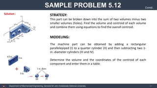
  • 37. Department of Mechanical Engineering, General Sir John Kotelawala Defence University 38 SAMPLE PROBLEM 5.12 Contd.. STRATEGY: This part can be broken down into the sum of two volumes minus two smaller volumes (holes). Find the volume and centroid of each volume and combine them using equations to find the overall centroid. Solution : The machine part can be obtained by adding a rectangular parallelepiped (I) to a quarter cylinder (II) and then subtracting two 1- in.-diameter cylinders (III and IV). Determine the volume and the coordinates of the centroid of each component and enter them in a table. MODELING:
  • 38. Department of Mechanical Engineering, General Sir John Kotelawala Defence University 39 SAMPLE PROBLEM 5.12 Contd.. Solution : ANALYSIS: Centroids of components.
  • 39. Department of Mechanical Engineering, General Sir John Kotelawala Defence University 40 SAMPLE PROBLEM 5.12 ( ) ( ) 3 4 in .286 5 in 048 . 3 = =   V V x X ( ) ( ) 3 4 in .286 5 in 5.047 − = =   V V y Y ( ) ( ) 3 4 in .286 5 in .555 8 = =   V V z Z in. 577 . 0 = X in. 955 . 0 − = Y in. 618 . 1 = Z Contd..
  • 40. Department of Mechanical Engineering, General Sir John Kotelawala Defence University 41 SAMPLE PROBLEM 5.13 A body consisting of a cone and hemisphere of radius r fixed on the same base rests on a table, the hemisphere being in contact with the table. Find the greatest height of the cone, so that the combined body may stand upright.
  • 41. Department of Mechanical Engineering, General Sir John Kotelawala Defence University 42 SAMPLE PROBLEM 5.13
  • 42. Department of Mechanical Engineering, General Sir John Kotelawala Defence University 43 SAMPLE PROBLEM 5.13
  • 43. Department of Mechanical Engineering, General Sir John Kotelawala Defence University 44 REFERENCES ❖ Vector Mechanics for Engineers – Statics and Dynamics (11th Ed.), Beer F.P., Johnston E.T. Jr., McGraw-Hill, INC
  • 44. 45