SlideShare a Scribd company logo
Building Project (SPC1)
Design of Concrete Beam
Done by: Eng.S.Kartheepan (M.Sc, B.Eng, AMIESL, AMIIESL)
Department of Civil Engineering
IET, Katunayake
E-mail: karthee2087@gmail.com
Principle in beam design
• Normally in beam design, the effective depth of beam is
determined the ratio between span/effective depth is less or
equal to 15. (l/d <=15)
• This should be performed in the initial stage of design after that
design calculation for beam will be executed and finally the
deflection check will be carried out to make sure the particular
effective depth.
• Normally in continuous beam design, load cases are going to do
for finding the critical bending moment and critical shear force.
Flanged Beam
• The depth of neutral axis in relation to the depth of the
flange will influence the design process.
• The neutral axis of the beam is given below
• When the neutral axis lies within the flange (hf), the
breadth of the beam at mid- span is equal to the effective
flange width (bf).
x<hf – Flanged beam action
• If x>hf then the breadth is taken as the actual width of
the beam (bw)
Effective span – for continuous beam the effective span should
normally taken as the distance between the centres of supports
Effective Flange width
Effective width of flanged beam ?
(BS8110-1997-Part – 01)
Effective Flange width
Effective width of flanged beam?
• The In the absence of any more accurate determination this
should be taken as:
a) for T-beams:web width + lz/5 or actual flange width
b) for L-beams:web width + lz/10 or actual flange width
Where:
• lz - is the distance between points of zero moment (which, for
a continuous beam, may be taken as 0.7 times the effective
span)
Load distributions and moments
Fixed End Moments
Example
Fixed End Moments
Example
Fixed End Moments
Fixed End Moments
Fixed End Moments
Fixed End Moments
Continuous beam design
• After the finding the fixed end moments in each span of the
beam, moment distribution will be carried out to finding the
final bending moments in each cases.
• Load cases are very important to finding the final design
bending moment from all cases and also critical bending
moments and shear forces can be found.
• Moment distribution is already discussed in slab design and
follow the same approach.
Principle in beam design
• If the number of span is two then there are three cases will
be taken in analysis.
• How ever, if the number of span is more than three, those
cases also three cases will be selected.
Example:
1. Load case – 01: all spans loaded with 1.4Gk+1.6Qk
2. Load case – 02: alternate spans loaded with1.4Gk+1.6Qk
3. Load case – 03: alternate spans loaded with 1.4Gk+ 1.6Qk
Principle in beam design
Example
Principle in beam design
Case No: 01
Principle in beam design
Case No: 02
Principle in beam design
Case No: 03
Shear Force Diagram
Bending Moment Diagram
Classification of exposure conditions (Table 3.2,
BS8110, 1997, Part - 01)
Nominal cover to all reinforcement (including links)
to meet durability requirements (Table 3.3, BS 8110,
1997)
Nominal cover to all reinforcement (including links) to
meet specified periods of fire resistance (Table 3.4, BS
8110, 1997)
Design formula
Reynold’s Hand book
Minimum Reinforcement
Bar Spacing in Beam
Shear check in Beam
Shear check in Beam
Design Concrete Shear Stress
Bent-up bar
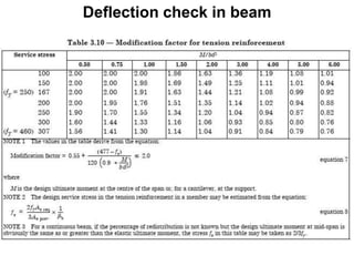
Deflection check in beam
Crack control in beam
Curtailment detailing in reinforcement work
Curtailment is a way of reducing the area of tensile reinforcement
at points/areas (either on a beam/slab) where bending moment is
minimum or zero for the purpose of achieving an economic
design.
Simplified rules for beam
Curtailment of Reinforcement in Beams: Reinforcements are
curtailed along its length in beams depending on the bending
moment at the section. Anchorage or development length
required at support is provided during curtailment of
reinforcement.
Curtailment detailing in reinforcement work
BS8110 – 1997 – Part – 01 , Clause 3.12.10.2 in Figure 3.24 as
well as BS8110 – 1985 – Part – 01 , Clause 3.12.9 detailed the
rules.
Curtailment detailing in reinforcement work
Simplified rules for beam
a) Simply support beam
In the simply supported beam since the moment is nearly zero at
the ends and the tension stresses also reduces so the tension
bars are curtailed.
Curtailment detailing in reinforcement work
Simplified rules for beam
b) Continuous beam
In the continuous beam there is negative moment at the
intermediate support so 100% bars are provided at the top but as
negative moment decreases so 60% steel is used.
Curtailment detailing in reinforcement work
b) Continuous beam
b) Continuous beam
Curtailment detailing in reinforcement work
C) Cantilever beam
C) Cantilever beam
Lap Length in Beam
In case of beam we generally use 24d for compression zone and 45d for
tensile/tension zone
• Lapping (24d) in top bars avoided L/3 distance from both end. For top bar
lapping should be at mid span.
• Lapping (45d) in bottom bars lap should be provided at column junction or
L/4 distance from column face but should not be in mid span of beam.
• Stirrups should be closely spaced near the columns and lose/normal at mid
span.
• Lapping of bars should be alternately provided
Lap position in Beam, Column and Slab
Laps:
- between bars should normally be staggered and not located in
areas of high moments

More Related Content

PPTX
Introduction of Reinforced Concrete Design
PPTX
Design of floor slab
PDF
T beam TYPES
PDF
BBS Preparation
PDF
COMPOSITE BEAMS.pdf
PDF
Calulation of deflection and crack width according to is 456 2000
PDF
Combined footing 1-1-18
PPT
Design of slender columns as per IS 456-2000
Introduction of Reinforced Concrete Design
Design of floor slab
T beam TYPES
BBS Preparation
COMPOSITE BEAMS.pdf
Calulation of deflection and crack width according to is 456 2000
Combined footing 1-1-18
Design of slender columns as per IS 456-2000

What's hot (20)

PPTX
Design of beams
PDF
Doubly reinforced beams...PRC-I
PPTX
Compression member
PDF
Bs8110 design notes
PPTX
BOLTED CONNECTION
PPTX
ONE WAY SLAB DESIGN
PPTX
Design of R.C.C Beam
PPT
Reinforcement detailing
PPTX
Reinforced column design
PPTX
Staircase design
PPTX
Connections in steel structures
PPTX
PPTX
Two Way Slabs
PPTX
Beams and columns
PDF
Design of pile foundation
PPTX
post tensioning slabs
PPTX
Design of Concrete Structure 1
PPTX
Two way slab
PPTX
Unit I Losses of prestress and deflection
Design of beams
Doubly reinforced beams...PRC-I
Compression member
Bs8110 design notes
BOLTED CONNECTION
ONE WAY SLAB DESIGN
Design of R.C.C Beam
Reinforcement detailing
Reinforced column design
Staircase design
Connections in steel structures
Two Way Slabs
Beams and columns
Design of pile foundation
post tensioning slabs
Design of Concrete Structure 1
Two way slab
Unit I Losses of prestress and deflection
Ad

Similar to Design of concrete beam (20)

PPTX
BTech Sem 3 notes.pptxARARQQDWQEE2E2DSR4E WR3RD3 V
PPTX
DESIGN OF RC BEAMS
PDF
Concrete beam design
PDF
L6 - Beam Design.pdf
PDF
Design of Beam- RCC Singly Reinforced Beam
PDF
Design of reinforced concrete beam
PDF
04 ec2 ws_walraven_ulssls
PDF
T-Beams - Limit State Method - Building Construction
PPTX
Design Of Continuous Beams 30_8.pptx
PPT
Analysis of T-Beam
PPTX
3 Beams.pptx
PDF
Formulas for RCC.pdf
PPT
rectangular and section analysis in bending and shear
PPT
Design of singly reinforced.
PDF
Beamand slab design
PDF
Beam and slab design
PPT
fdocuments.in_design-of-singly-reinforced-5681874f52c1b.ppt
DOCX
Chapter 3 (rib)MOSTAFA
PDF
Lec11 Continuous Beams and One Way Slabs(1) (Reinforced Concrete Design I & P...
PPSX
Design of singly reinforced.
BTech Sem 3 notes.pptxARARQQDWQEE2E2DSR4E WR3RD3 V
DESIGN OF RC BEAMS
Concrete beam design
L6 - Beam Design.pdf
Design of Beam- RCC Singly Reinforced Beam
Design of reinforced concrete beam
04 ec2 ws_walraven_ulssls
T-Beams - Limit State Method - Building Construction
Design Of Continuous Beams 30_8.pptx
Analysis of T-Beam
3 Beams.pptx
Formulas for RCC.pdf
rectangular and section analysis in bending and shear
Design of singly reinforced.
Beamand slab design
Beam and slab design
fdocuments.in_design-of-singly-reinforced-5681874f52c1b.ppt
Chapter 3 (rib)MOSTAFA
Lec11 Continuous Beams and One Way Slabs(1) (Reinforced Concrete Design I & P...
Design of singly reinforced.
Ad

Recently uploaded (20)

PPTX
IOT PPTs Week 10 Lecture Material.pptx of NPTEL Smart Cities contd
DOCX
ASol_English-Language-Literature-Set-1-27-02-2023-converted.docx
PPT
Mechanical Engineering MATERIALS Selection
PPTX
Lecture Notes Electrical Wiring System Components
PDF
Evaluating the Democratization of the Turkish Armed Forces from a Normative P...
PDF
Mitigating Risks through Effective Management for Enhancing Organizational Pe...
PPTX
MCN 401 KTU-2019-PPE KITS-MODULE 2.pptx
PDF
SM_6th-Sem__Cse_Internet-of-Things.pdf IOT
PPTX
web development for engineering and engineering
PPTX
CARTOGRAPHY AND GEOINFORMATION VISUALIZATION chapter1 NPTE (2).pptx
PDF
The CXO Playbook 2025 – Future-Ready Strategies for C-Suite Leaders Cerebrai...
PPTX
Foundation to blockchain - A guide to Blockchain Tech
PPTX
CH1 Production IntroductoryConcepts.pptx
PPTX
M Tech Sem 1 Civil Engineering Environmental Sciences.pptx
PPTX
bas. eng. economics group 4 presentation 1.pptx
PPTX
Internet of Things (IOT) - A guide to understanding
PPTX
UNIT-1 - COAL BASED THERMAL POWER PLANTS
PPTX
additive manufacturing of ss316l using mig welding
PPTX
Welding lecture in detail for understanding
PPT
Project quality management in manufacturing
IOT PPTs Week 10 Lecture Material.pptx of NPTEL Smart Cities contd
ASol_English-Language-Literature-Set-1-27-02-2023-converted.docx
Mechanical Engineering MATERIALS Selection
Lecture Notes Electrical Wiring System Components
Evaluating the Democratization of the Turkish Armed Forces from a Normative P...
Mitigating Risks through Effective Management for Enhancing Organizational Pe...
MCN 401 KTU-2019-PPE KITS-MODULE 2.pptx
SM_6th-Sem__Cse_Internet-of-Things.pdf IOT
web development for engineering and engineering
CARTOGRAPHY AND GEOINFORMATION VISUALIZATION chapter1 NPTE (2).pptx
The CXO Playbook 2025 – Future-Ready Strategies for C-Suite Leaders Cerebrai...
Foundation to blockchain - A guide to Blockchain Tech
CH1 Production IntroductoryConcepts.pptx
M Tech Sem 1 Civil Engineering Environmental Sciences.pptx
bas. eng. economics group 4 presentation 1.pptx
Internet of Things (IOT) - A guide to understanding
UNIT-1 - COAL BASED THERMAL POWER PLANTS
additive manufacturing of ss316l using mig welding
Welding lecture in detail for understanding
Project quality management in manufacturing

Design of concrete beam

  • 1. Building Project (SPC1) Design of Concrete Beam Done by: Eng.S.Kartheepan (M.Sc, B.Eng, AMIESL, AMIIESL) Department of Civil Engineering IET, Katunayake E-mail: karthee2087@gmail.com
  • 2. Principle in beam design • Normally in beam design, the effective depth of beam is determined the ratio between span/effective depth is less or equal to 15. (l/d <=15) • This should be performed in the initial stage of design after that design calculation for beam will be executed and finally the deflection check will be carried out to make sure the particular effective depth. • Normally in continuous beam design, load cases are going to do for finding the critical bending moment and critical shear force.
  • 3. Flanged Beam • The depth of neutral axis in relation to the depth of the flange will influence the design process. • The neutral axis of the beam is given below • When the neutral axis lies within the flange (hf), the breadth of the beam at mid- span is equal to the effective flange width (bf). x<hf – Flanged beam action • If x>hf then the breadth is taken as the actual width of the beam (bw) Effective span – for continuous beam the effective span should normally taken as the distance between the centres of supports
  • 4. Effective Flange width Effective width of flanged beam ? (BS8110-1997-Part – 01)
  • 5. Effective Flange width Effective width of flanged beam? • The In the absence of any more accurate determination this should be taken as: a) for T-beams:web width + lz/5 or actual flange width b) for L-beams:web width + lz/10 or actual flange width Where: • lz - is the distance between points of zero moment (which, for a continuous beam, may be taken as 0.7 times the effective span)
  • 15. Continuous beam design • After the finding the fixed end moments in each span of the beam, moment distribution will be carried out to finding the final bending moments in each cases. • Load cases are very important to finding the final design bending moment from all cases and also critical bending moments and shear forces can be found. • Moment distribution is already discussed in slab design and follow the same approach.
  • 16. Principle in beam design • If the number of span is two then there are three cases will be taken in analysis. • How ever, if the number of span is more than three, those cases also three cases will be selected. Example: 1. Load case – 01: all spans loaded with 1.4Gk+1.6Qk 2. Load case – 02: alternate spans loaded with1.4Gk+1.6Qk 3. Load case – 03: alternate spans loaded with 1.4Gk+ 1.6Qk
  • 18. Principle in beam design Example
  • 19. Principle in beam design Case No: 01
  • 20. Principle in beam design Case No: 02
  • 21. Principle in beam design Case No: 03
  • 24. Classification of exposure conditions (Table 3.2, BS8110, 1997, Part - 01)
  • 25. Nominal cover to all reinforcement (including links) to meet durability requirements (Table 3.3, BS 8110, 1997)
  • 26. Nominal cover to all reinforcement (including links) to meet specified periods of fire resistance (Table 3.4, BS 8110, 1997)
  • 39. Curtailment detailing in reinforcement work Curtailment is a way of reducing the area of tensile reinforcement at points/areas (either on a beam/slab) where bending moment is minimum or zero for the purpose of achieving an economic design. Simplified rules for beam Curtailment of Reinforcement in Beams: Reinforcements are curtailed along its length in beams depending on the bending moment at the section. Anchorage or development length required at support is provided during curtailment of reinforcement.
  • 40. Curtailment detailing in reinforcement work BS8110 – 1997 – Part – 01 , Clause 3.12.10.2 in Figure 3.24 as well as BS8110 – 1985 – Part – 01 , Clause 3.12.9 detailed the rules.
  • 41. Curtailment detailing in reinforcement work Simplified rules for beam a) Simply support beam In the simply supported beam since the moment is nearly zero at the ends and the tension stresses also reduces so the tension bars are curtailed.
  • 42. Curtailment detailing in reinforcement work Simplified rules for beam b) Continuous beam In the continuous beam there is negative moment at the intermediate support so 100% bars are provided at the top but as negative moment decreases so 60% steel is used.
  • 43. Curtailment detailing in reinforcement work b) Continuous beam
  • 45. Curtailment detailing in reinforcement work C) Cantilever beam
  • 47. Lap Length in Beam In case of beam we generally use 24d for compression zone and 45d for tensile/tension zone • Lapping (24d) in top bars avoided L/3 distance from both end. For top bar lapping should be at mid span. • Lapping (45d) in bottom bars lap should be provided at column junction or L/4 distance from column face but should not be in mid span of beam. • Stirrups should be closely spaced near the columns and lose/normal at mid span. • Lapping of bars should be alternately provided
  • 48. Lap position in Beam, Column and Slab Laps: - between bars should normally be staggered and not located in areas of high moments