


Instrumentation of uv visible spectroscopy
- 1. INSTRUMENTATION OF UV-VISIBLE SPECTROSCOPY Prepared by, Nilam Mistry Roshni Panchal 1st Sem M.Pharm (Pharmaceutical chemistry) Parul institute of Pharmacy 1
- 2. CONTENTS: o Introduction o Components o Light source o Monochromator o Sample holder o Detectors o Instrumentation design o Reference videos 2
- 3. INTRODUCTION: Spectroscopy is the branch of science that deals with the study of interaction of electro-magnetic radiation (EMR) with matter. Instrument used to measure the absorbance in UV (200-400nm) or Visible (400-800nm) region is called UV-Visible Spectrophotometer. A Spectrophotometer records the degree of absorption by a sample at different wavelengths and the resulting plot of absorbance (A) versus wavelength (λ) is known as Spectrum. 3
- 4. 4
- 5. COMPONENTS: Light sources Monochromator Sample holder Detector Recorder 5
- 6. LIGHT SOURCE Requirements: It should be stable. It should provide continuous radiation. It must be of the sufficient intensity for the transmitted energy to be detected at the end of the optical path. 6
- 7. 1.HYDROGEN AND DEUTERIUM DISCHARGE LAMPS A continuous spectrum in the UV region is produced by electrical excitation of deuterium or hydrogen at low pressure. Range: 3500-1200A (160-800nm) These are stable, robust and widely used. If deuterium lamp is used instead of hydrogen lamp it increase the emission intensity. Deuterium lamp is more expensive then hydrogen lamp but are used when higher intensity is required. 7
- 8. Hydrogen Lamp Deuterium Lamp 8
- 9. 2.TUNGSTEN FILAMENT LAMP It is the most common light source used in a spectrophotometer. Also called as “Quartz halogen lamp” These lamp consists of a tungsten filament enclosed in a glass envelope, with a wavelength range of about 320-2500nm, are used for the visible region. Quartz allows the filament to be operated at a temperature of about 3500K which leads to higher intensity in a UV region. 9
- 10. 3.XENONE ARC LAMP Xenone gas is stored in a lamps at 10-30 atm pressure. It contain 2 tungsten electrodes that are separated by a distance of about 8mm. When current passes through xenone cause thermal excitation. It produces greater UV radiation then the hydrogen lamp. It is a continuous source. 10
- 11. 4.MERCURY ARC LAMP In this mercury vapour is stored under high pressure and the excitation of mercury atoms is done by electric discharge. It is not suitable for continuous radiations. 11
- 12. MONOCHROMATORS It is a device used to isolate the radiation of the wavelength from wavelength of the continuous spectra. These are types of monochromatic devices. Filters Prisms Grating 12
- 13. 1.FILTERS Selection of filters is usually done on a compromise between peak transmittance and band pass width; the former should be as high as possible and latter as narrow as possible. TYPES OF FILTERS: 1. Absorption filters 2. Interference filters 13
- 14. Types Of Works by selective absorption of unwanted radiation and transmits the radiation which is required. Examples – Glass and Gelatin filters. These is less accurate Merits: Simple in construction Cheaper Filters Works on the interference phenomenon, cause rejection of unwanted wavelength by selective reflection. It is constructed by using 2 parallel glass plates, which are silvered internally and separated by thin film of dielectric material of different (CaF2, MgF2) refractive index. Provide greater transmittance and narrower band pass (10- 15nm) 14 Absorption Filters Interference Filters
- 15. 2.PRISM Prism is made from glass, Quartz or fused silica. Quartz or fused silica is the choice of material of UV spectrum. When white light is passed through glass prism, dispersion of polychromatic light in rainbow occurs. Now by rotation of the prism different wavelength of the spectrum can be made to pass through in exit slit on the sample. The effective wavelength depends on the dispersive power of prism material and the optical angle of the prism. 15
- 16. 16
- 17. 3.GRATINGS Gratings are most effective one in converting a polychromatic light to monochromatic light. As a resolution of +/- 0.1nm could be achieved by using gratings. MERITS:- o Grating gives higher and liner dispersions compared to prism monochromator. o Can be used over wide wavelength ranges. o Gratings can be construed with like materials aluminium which is resistant to atmospheric moisture. o Provide light of narrow wavelength. o No loss of energy due to absorption 17
- 18. TYPES OF GRATINGS: 1. DEFRACTION GRATING More refined dispersion of light is obtained by means of diffraction grating. These consist of large number of parallel lines (grooves) about 15000- 30000/ inch is ruled on highly polished surface of aluminum. These gratings are replica made from master gratings by coating the original master grating with a epoxy resin and are removed after setting. To make the surface reflective, a deposit of aluminum is made on the surface. In order to minimize to greater amounts of scattered radiation and appearance of unwanted radiation of other spectral orders, the gratings are blazed to concentrate the radiation into a single order. 2. TRANSMISSION GRATING It is similar to diffraction grating but refraction takes place instead of reflection. Refraction produces reinforcement. This occurs when radiation transmitted through grating reinforcement with the partially refracted radiation 18
- 19. SLITS AND MIRRORS Slits are an important device in a resolving polychromatic radiation into monochromatic radiation. To archive these, entrance slit and exit slit are used. The width of slit plays a important role in resolution of polychromatic radiation. Mirrors are used to reflect, focus light beams in a spectrophotometers. To minimize the light loss, mirrors are aluminized on there front surfaces. 19
- 20. SAMPLE HOLDER The cells or cuvettes are used for handling liquid samples. The cell may either be rectangular or cylindrical in nature. For study in UV region, the cells are prepared from quartz or fused silica whereas colour corrected fused glass is used for visible region. The surfaces of absorption cells must be kept clean. No fingerprints or blotches should be present on cells. Cleaning is carried out washing with distilled water or with dilute alcohol, acetone. 20
- 21. DETECTORS Device which converts light energy into electrical signals, that are displayed on readout devices. The transmitted radiation falls on the detector which determines the intensity of radiation absorbed by sample. Requirements of an ideal detector:- It should give quantitative response. It should have high sensitivity and low noise level. It should have a short response time. TYPES OF DETECTORS 1. Barrier layer cell/Photovoltaic cell 2. Phototubes/ Photo emissive cell 3. Photomultiplier tube 21
- 22. 1.BARRIER LAYER CELL The detector has a thin film metallic layer coated with silver or gold and acts as an electrode. It also has a metal base plate which acts as another electrode. These two layers are separated by a semiconductor layer of selenium . When light radiation falls on selenium layer , electrons become mobile and are taken up by transparent metal layer. This creates a potential difference between two electrodes and causes the flow of current. When it is connected to galvanometer, a flow of current observed which is proportional to the intensity and wavelength of light falling on it. Also called as photovoltaic cell 22
- 23. 23
- 24. 2.PHOTO-EMMISSIVE TUBES Consists of a evacuated glass tube with a photocathode and a collector anode. The surface of photocathode is coated with a layer of elements like caesium, silver oxide or mixture of them. When radiant energy falls on photosensitive cathode, electrons are emitted which are attracted to anode causing current to flow. More sensitive compared to barrier layer cell and therefore widely used. 24
- 25. 25
- 26. 3.PHOTO MULTIPLIER TUBE The principle employed in this detector is that , multiplication of photoelectrons by secondary emission of electrons. In a vacuum tube, a primary photo-cathode is fixed which receives radiation from the sample. Some eight to ten dynodes are fixed each with increasing potential of 75-100V higher than preceding one. Near the last dynode is fixed an anode or electron collector electrode. Photo-Multiplier is extremely sensitive to light and is best suited where weaker or low radiation is received 26
- 28. AMPLIFIER AND RECORDER Amplifier amplifies signal coming from detector Recorder records them which is displayed on readout device. 28
- 29. INSTRUMENTATION DESIGN Depending upon the monochromators (filters or dispersing device ) used to isolate and transmit a narrow beam of radiant energy from the incident light determines whether the instrument is classified as Photometer or a Spectrophotometer. Spectrophotometer used here detects the percentage transmittance of light radiation, when light of certain intensity and frequency range is passed through the sample. Both can be a single beam or double beam optical system. 29
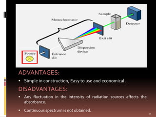
- 30. SINGLE BEAM SPECTROPHOTOMETER Light from the source is carried through lens or aperture to pass through a suitable filter. The type of filter to be used is governed by the colour of the solution. The sample solution to be analysed is placed in cuvettes. After passing through the solution, the light strikes the surface of detector (barrier-layer cell or phototube) and produces electrical current. The output of current is measured by the deflection of needle of light-spot galvanometer or micro ammeter. This meter is calibrated in terms of transmittance as well as optical density. The reading of solution of both standard and unknown are recorded in optical density unit a after adjusting instrument to a reagent blank. 30
- 31. ADVANTAGES: Simple in construction, Easy to use and economical . DISADVANTAGES: Any fluctuation in the intensity of radiation sources affects the absorbance. Continuous spectrum is not obtained. 31
- 32. DOUBLE BEAM SPECTROPHOTOMETER Double beam instrument is the one in which two beams are formed in the space by a ‘U’ shaped mirror called as beam splitter or beam chopper. Chopper is a device consisting of a circular disc. One third of the disc is opaque and one third is transparent, remaining one third is mirrored. It splits the monochromatic beam of light into two beams of equal intensities. 32
- 33. ` 33 D ADVANTAGES: It facilitates rapid scanning over wide (λ) region. Fluctuations due to radiation source are minimised. It gives ratio of intensities of sample and reference beams simultaneously. DISADVANTAGES: Construction is complicated. Instrument is expensive.
- 34. 34
- 35. REFERENCE VIDEOS: https://www.youtube.com/watch?v=pxC6F7b K8CU https://www.youtube.com/watch?v=sVc- XIysw0c https://youtu.be/lQTsN5pHmKc https://youtu.be/XAp-5r3LxQo https://youtu.be/jyDXjQDxb-8 https://www.directindustry.com/prod/nanodr op/product-36205-1688787.html 35
- 36. 36
- 37. THANK YOU 37
Editor's Notes
- #25: Evacuated means removal of water air or other contents