SlideShare a Scribd company logo
1
Chapter 4
Dynamic Modeling and Analysis
(Part I)
Object-Oriented Technology
From Diagram to Code with Visual Paradigm for UML
Curtis H.K. Tsang, Clarence S.W. Lau and Y.K.
Leung
McGraw-Hill Education (Asia), 2005
2
References
 Chapter 4, Object-Oriented Technology:
From diagram to code with Visual
Paradigm for UML
 Chapters 15, 18, 21, The UML User
Guide
3
What You Will Learn
 Model message flows using sequence
diagrams.
 Model message flows using the collaboration
diagrams.
 Model lifetime behaviors of an object using
state chart diagrams.
 Model performance of actions of a procedure
or an activity using activity diagrams.
4
Scenario Modeling
Techniques – Interaction
Diagramme
 Scenario modeling describes how the objects
in a system interact with each other in a
scenario.
 A scenario is a sequence of events that
occurs during one particular execution path
within a use case of a system.
 Each event involves the interaction of objects
passing messages between them.
5
Scenario Modeling
Techniques – Interaction
Diagramme (cont’d)
 An interaction diagram can be used to model the
collaborating objects in scenarios, showing the
 objects involved in the scenario and
 the messages sent and received by them.
 These objects may be external or internal to the system.
 The messages represent the invocation of operations of
the receiving objects.
 Two kinds of interaction diagrams: sequence diagrams
and collaboration diagrams.
 Sequence diagrams focus on the time sequencing of
messages.
 Collaboration diagrams focus on the structural
organization of the links between collaborating objects.
6
Common UML Interaction
Diagram Notation
 Object Symbol
Naming Format Notation
An object of an unspecified
class.
A named object of a specified
class.
An unnamed object of a
specified class.
7
Object Stereotype
Object
Category
Description Graphical Notations
Actor Object An external entity that
interacts with the
system.
Entity Object An object that models
the data in the system.
It often represents an
object in the problem
domain.
8
Object Stereotype (cont’d)
Object
Category
Description Graphical Notations
Boundary
Object
An object that handles
the communication
between actor objects
and the system.
Control Object An object that models
the flow of control and
functionality that do
not naturally belong to
entity objects or
boundary objects.
9
Messages
Message Description Notation
Procedure call or
other nested flow
of control
The message sender waits
for the completion of the
procedure call of the
message receiver.
Asynchronous
communication
The sender dispatches a
message and immediately
continues with the next step
of execution.
10
Messages (cont’d)
Message Description Notation
Return message Message returned from the
procedure call.
Message with
travel delay
The message will take a
significant amount of time to
arrive at the receiving
object. (This is only used in
sequence diagrams.)
11
Sequence Diagrams
 Interaction diagram: models the behavior of a
group of objects that work together to achieve a
user goal.
 A sequence diagram helps us identify a set of
collaborating objects involved in a scenario of a use
case.
 A sequence diagram has two dimensions: the
vertical dimension and the horizontal dimension,
respectively
 Object icons are placed horizontally at the top of the
sequence diagram, and messages are passed
between them.
12
Sequence Diagrams (cont’d)
13
Life Line & Activation
Object with
Lifeline
Object with
Activation
14
Creation & Destruction
Object
Destruction
Object
Destruction
15
Branching
Conditional
Message
Transmission
16
Message that Takes Time
Message Transmission that Takes Time
17
Iteration
Iteration
18
Alternate Message Reception
Alternate
Message
Reception
19
Recursion
Recursion
20
Example
Life line
Creation
Deletion
21
Example
Life line
Activation
iteration
22
Example
Life line
collective
iteration
23
Example
Concurrent
Branch
24
Collaboration Diagrams
 Collaboration diagrams provide another way to model a
scenario.
 Shows the roles of objects and associations of objects in an
instance of collaboration.
 Focus on structures of the objects rather than temporal
sequence of operations.
 In a collaboration diagram, each object is represented by an
object icon, and links are used to indicate communication paths
on which messages are transmitted.
 Collaboration diagram = object diagram + messages between
objects.
 Messages are presented in the same way as those in a
sequence diagram; in fact, sequence diagrams and
collaboration diagrams are semantically equivalent.
25
Collaboration Diagrams
(cont’d)
26
Example – Telephone System
27
Example – Message with Duration
28
Example – An Automatic
Teller Machine (ATM)
 The ATM prompts the user to insert a card.
 The user inserts an ATM card.
 The ATM prompts the user to input the PIN.
 The user enters the PIN.
 The ATM asks the bank consortium to verify the ATM card number and
PIN.
 The bank consortium verifies the ATM card number and PIN with bank.
 The bank notifies the bank consortium that the PIN is correct.
 The bank consortium notifies the ATM the PIN is correct.
 The ATM prompts the user to select a service.
 The user selects the withdraw cash service.
 The ATM prompts the user to enter the amount to withdraw.
29
Example 1 – An Automatic
Teller Machine (cont’d)
 The user enters the amount to withdraw.
 The ATM asks the bank consortium to process the request. The bank
consortium forwards the request to bank.
 The bank confirms the successful execution of the request to the bank
consortium which in turn notifies the ATM that the request has been
approved.
 The ATM displays the successful transaction screen, ejects card and
then dispenses cash requested.
 The ATM shows the main menu to the user for selecting the next
service.
30
Example – An Automatic
Teller Machine (cont’d)
31
Example – An Automatic
Teller Machine (cont’d)
32
Example – An Automatic
Teller Machine (cont’d)
33
Example - A Soft Drink
Vending Machine
34
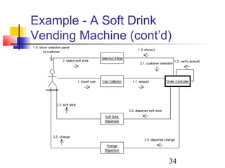
Example - A Soft Drink
Vending Machine (cont’d)
35
Dynamic Modeling Techniques
Using Statechart Diagrams
 The behavior of an entity is not only a direct
consequence of its inputs, but it also depends on its
preceding state.
 The past history of an entity can best be modeled by
a finite statechart diagram traditionally named
“automata”.
 Statechart diagrams (or sometimes referred to as
state diagrams) show the different states of an entity.
 Statechart diagrams can also show how an entity
responds to various events by changing from one
state to another.  
36
What Is a State?
 According to Rumbaugh et al. “A state is an
abstraction of the attribute values and links of an
object. Sets of values are grouped together into a
state according to properties that affect the gross
behavior of the object.”
 For example, consider you have $100,000 in a
bank account. The behavior of the withdraw
function would be:
 balance := balance – withdrawAmount; provided that the
balance after the withdrawal is not less than $0;
 However, if the account balance becomes negative after
a withdrawal, the behavior of the withdraw function would
be quite different.
37
What Is a State?(cont’d)
 There are several characteristics of states:
 A state occupies an interval of time.
 A state is often associated with an abstraction of
attribute values of an entity satisfying some condition(s).
 An entity changes its state not only as a direct
consequence of the current input, but it is also
dependent on some past history of its inputs.
38
UML Notation
39
UML Notation (cont’d)
Action or activity Description
entry/ action 1; …; action n Upon entry to the state, the specified
actions are performed.
exit/ action 1; …; action n Upon exit from the state, the specified
actions are performed.
do/ activity The specified activity is performed
continuously while in this state.
event-name(parameters)
[guard-condition] / action
1 ; …; action n
An internal transition is fired when the
specified event occurs and the
specified guard condition is true. The
specified actions are performed when
the transition is fired.
40
UML Notation (cont’d)
Initial state
Final state
State
History state
Junction state
Concurrent composite state
Transition
41
Transition
 A transition from one state to another
takes place instantaneously in response
to some external events or internal
stimuli.
42
Transition (cont’d)
 A transition is fired when the following
conditions are satisfied:
 The entity is in the state of the source state.
 An event specified in the label occurs.
 The guard condition specified in the label is
evaluated to be true.
 When a transition is fired, the actions
associated with it are executed.
43
Composite State
44
Composite State (cont’d)

More Related Content

PPT
PPT
Unit 3(advanced state modeling & interaction meodelling)
PPTX
PPT
M03 2 Behavioral Diagrams
PPT
7. sequence and collaboration diagrams
 
PDF
CS8592 Object Oriented Analysis & Design - UNIT III
PPT
Pertemuan 6-2-sequence-diagram
PPTX
state modeling In UML
Unit 3(advanced state modeling & interaction meodelling)
M03 2 Behavioral Diagrams
7. sequence and collaboration diagrams
 
CS8592 Object Oriented Analysis & Design - UNIT III
Pertemuan 6-2-sequence-diagram
state modeling In UML

What's hot (20)

PPT
5.state diagrams
 
PDF
Software Engineering :Behavioral Modelling - II State diagram
PPT
Software System Engineering - Chapter 14
PPT
Slide 4 Interaction Diagram
PPT
Software System Engineering - Chapter 12
PPT
Ooad ch 5
PDF
Recognition of Handwritten Mathematical Equations
PDF
Unified Modeling Language (UML), Object-Oriented Programming Concepts & Desig...
PDF
Free ebooks download ! Edhole
PPT
08 state diagram and activity diagram
PDF
Lesson 32
PPTX
Uml Diagrams
PDF
State chart diagram
PPT
Software System Engineering - Chapter 13
PDF
Machine learning Mind Map
PPT
State Diagrams
PDF
Deep learning MindMap
PDF
Analysis and Design of Algorithms notes
PPTX
UML tutorial
PDF
mit-watch-what-i-do-chronology
5.state diagrams
 
Software Engineering :Behavioral Modelling - II State diagram
Software System Engineering - Chapter 14
Slide 4 Interaction Diagram
Software System Engineering - Chapter 12
Ooad ch 5
Recognition of Handwritten Mathematical Equations
Unified Modeling Language (UML), Object-Oriented Programming Concepts & Desig...
Free ebooks download ! Edhole
08 state diagram and activity diagram
Lesson 32
Uml Diagrams
State chart diagram
Software System Engineering - Chapter 13
Machine learning Mind Map
State Diagrams
Deep learning MindMap
Analysis and Design of Algorithms notes
UML tutorial
mit-watch-what-i-do-chronology
Ad

Similar to Jar chapter 4, part 1 (20)

PDF
CS8592-OOAD Lecture Notes Unit-3
PDF
SE_Lec 09_ UML Behaviour Diagrams
PDF
SE18_Lec 10_ UML Behaviour and Interaction Diagrams
PPT
OOADPPT Lecture 5 The OOAD Presentation.pptx
PPT
vu-re-lecture-39 dynamic model of banking.ppt
PPT
UnifedModeeqwewqeqweqwewqewqelingLanguage.ppt
PPT
Jar chapter 4_part_ii
PPT
Chapter7
PPT
2.2. Software cycle Models-System_Models.ppt
PPTX
Module 2 17CS45
PPT
4 Activity & Statechart diagram.ppt4 Activity & Statechart diagram.ppt4 Activ...
PPTX
UML.pptx
PPTX
Use case model
DOCX
Case tool lab-Reg2013 by Karthick Raja
PPTX
Unit three Advanced State Modelling
PPTX
Object_Oriented_Design_Basic Behavioral Modeling.pptx
PPTX
08.Sequence Diagrams.pptx in cS to describe
PDF
3 interaction and_state_modeling
PPTX
System Modelling
CS8592-OOAD Lecture Notes Unit-3
SE_Lec 09_ UML Behaviour Diagrams
SE18_Lec 10_ UML Behaviour and Interaction Diagrams
OOADPPT Lecture 5 The OOAD Presentation.pptx
vu-re-lecture-39 dynamic model of banking.ppt
UnifedModeeqwewqeqweqwewqewqelingLanguage.ppt
Jar chapter 4_part_ii
Chapter7
2.2. Software cycle Models-System_Models.ppt
Module 2 17CS45
4 Activity & Statechart diagram.ppt4 Activity & Statechart diagram.ppt4 Activ...
UML.pptx
Use case model
Case tool lab-Reg2013 by Karthick Raja
Unit three Advanced State Modelling
Object_Oriented_Design_Basic Behavioral Modeling.pptx
08.Sequence Diagrams.pptx in cS to describe
3 interaction and_state_modeling
System Modelling
Ad

More from Reham Maher El-Safarini (20)

PDF
Global threat-landscape report by fortinet.
PDF
Dynamics AX/ X++
PDF
Microsoft sql-and-the-gdpr
PDF
AWS Cloud economics
PDF
Cloud skills development
PDF
AWS cloud adoption framework (caf)
PDF
Application and database migration workshop
PDF
Containers on AWS
PDF
Security and governance with aws control tower and aws organizations
PDF
Digital transformation on aws
PDF
Security in the cloud
PDF
2. migration, disaster recovery and business continuity in the cloud
PDF
1. aws overview
PPT
ssl for securing
PPTX
03 unity 3_d_part_2
PPTX
02 unity 3_d_part_1
PPTX
01 unity 3_d_introduction
PPTX
Global threat-landscape report by fortinet.
Dynamics AX/ X++
Microsoft sql-and-the-gdpr
AWS Cloud economics
Cloud skills development
AWS cloud adoption framework (caf)
Application and database migration workshop
Containers on AWS
Security and governance with aws control tower and aws organizations
Digital transformation on aws
Security in the cloud
2. migration, disaster recovery and business continuity in the cloud
1. aws overview
ssl for securing
03 unity 3_d_part_2
02 unity 3_d_part_1
01 unity 3_d_introduction

Recently uploaded (20)

PPTX
Introduction-to-Literarature-and-Literary-Studies-week-Prelim-coverage.pptx
PPTX
Microbial diseases, their pathogenesis and prophylaxis
PDF
VCE English Exam - Section C Student Revision Booklet
PDF
3rd Neelam Sanjeevareddy Memorial Lecture.pdf
PDF
Chapter 2 Heredity, Prenatal Development, and Birth.pdf
PPTX
GDM (1) (1).pptx small presentation for students
PPTX
PPT- ENG7_QUARTER1_LESSON1_WEEK1. IMAGERY -DESCRIPTIONS pptx.pptx
PDF
Classroom Observation Tools for Teachers
PDF
Supply Chain Operations Speaking Notes -ICLT Program
PDF
01-Introduction-to-Information-Management.pdf
PDF
The Lost Whites of Pakistan by Jahanzaib Mughal.pdf
PDF
Abdominal Access Techniques with Prof. Dr. R K Mishra
PPTX
school management -TNTEU- B.Ed., Semester II Unit 1.pptx
PPTX
1st Inaugural Professorial Lecture held on 19th February 2020 (Governance and...
PPTX
master seminar digital applications in india
PDF
Computing-Curriculum for Schools in Ghana
PPTX
202450812 BayCHI UCSC-SV 20250812 v17.pptx
PDF
O7-L3 Supply Chain Operations - ICLT Program
PDF
2.FourierTransform-ShortQuestionswithAnswers.pdf
PDF
O5-L3 Freight Transport Ops (International) V1.pdf
Introduction-to-Literarature-and-Literary-Studies-week-Prelim-coverage.pptx
Microbial diseases, their pathogenesis and prophylaxis
VCE English Exam - Section C Student Revision Booklet
3rd Neelam Sanjeevareddy Memorial Lecture.pdf
Chapter 2 Heredity, Prenatal Development, and Birth.pdf
GDM (1) (1).pptx small presentation for students
PPT- ENG7_QUARTER1_LESSON1_WEEK1. IMAGERY -DESCRIPTIONS pptx.pptx
Classroom Observation Tools for Teachers
Supply Chain Operations Speaking Notes -ICLT Program
01-Introduction-to-Information-Management.pdf
The Lost Whites of Pakistan by Jahanzaib Mughal.pdf
Abdominal Access Techniques with Prof. Dr. R K Mishra
school management -TNTEU- B.Ed., Semester II Unit 1.pptx
1st Inaugural Professorial Lecture held on 19th February 2020 (Governance and...
master seminar digital applications in india
Computing-Curriculum for Schools in Ghana
202450812 BayCHI UCSC-SV 20250812 v17.pptx
O7-L3 Supply Chain Operations - ICLT Program
2.FourierTransform-ShortQuestionswithAnswers.pdf
O5-L3 Freight Transport Ops (International) V1.pdf

Jar chapter 4, part 1

  • 1. 1 Chapter 4 Dynamic Modeling and Analysis (Part I) Object-Oriented Technology From Diagram to Code with Visual Paradigm for UML Curtis H.K. Tsang, Clarence S.W. Lau and Y.K. Leung McGraw-Hill Education (Asia), 2005
  • 2. 2 References  Chapter 4, Object-Oriented Technology: From diagram to code with Visual Paradigm for UML  Chapters 15, 18, 21, The UML User Guide
  • 3. 3 What You Will Learn  Model message flows using sequence diagrams.  Model message flows using the collaboration diagrams.  Model lifetime behaviors of an object using state chart diagrams.  Model performance of actions of a procedure or an activity using activity diagrams.
  • 4. 4 Scenario Modeling Techniques – Interaction Diagramme  Scenario modeling describes how the objects in a system interact with each other in a scenario.  A scenario is a sequence of events that occurs during one particular execution path within a use case of a system.  Each event involves the interaction of objects passing messages between them.
  • 5. 5 Scenario Modeling Techniques – Interaction Diagramme (cont’d)  An interaction diagram can be used to model the collaborating objects in scenarios, showing the  objects involved in the scenario and  the messages sent and received by them.  These objects may be external or internal to the system.  The messages represent the invocation of operations of the receiving objects.  Two kinds of interaction diagrams: sequence diagrams and collaboration diagrams.  Sequence diagrams focus on the time sequencing of messages.  Collaboration diagrams focus on the structural organization of the links between collaborating objects.
  • 6. 6 Common UML Interaction Diagram Notation  Object Symbol Naming Format Notation An object of an unspecified class. A named object of a specified class. An unnamed object of a specified class.
  • 7. 7 Object Stereotype Object Category Description Graphical Notations Actor Object An external entity that interacts with the system. Entity Object An object that models the data in the system. It often represents an object in the problem domain.
  • 8. 8 Object Stereotype (cont’d) Object Category Description Graphical Notations Boundary Object An object that handles the communication between actor objects and the system. Control Object An object that models the flow of control and functionality that do not naturally belong to entity objects or boundary objects.
  • 9. 9 Messages Message Description Notation Procedure call or other nested flow of control The message sender waits for the completion of the procedure call of the message receiver. Asynchronous communication The sender dispatches a message and immediately continues with the next step of execution.
  • 10. 10 Messages (cont’d) Message Description Notation Return message Message returned from the procedure call. Message with travel delay The message will take a significant amount of time to arrive at the receiving object. (This is only used in sequence diagrams.)
  • 11. 11 Sequence Diagrams  Interaction diagram: models the behavior of a group of objects that work together to achieve a user goal.  A sequence diagram helps us identify a set of collaborating objects involved in a scenario of a use case.  A sequence diagram has two dimensions: the vertical dimension and the horizontal dimension, respectively  Object icons are placed horizontally at the top of the sequence diagram, and messages are passed between them.
  • 13. 13 Life Line & Activation Object with Lifeline Object with Activation
  • 16. 16 Message that Takes Time Message Transmission that Takes Time
  • 24. 24 Collaboration Diagrams  Collaboration diagrams provide another way to model a scenario.  Shows the roles of objects and associations of objects in an instance of collaboration.  Focus on structures of the objects rather than temporal sequence of operations.  In a collaboration diagram, each object is represented by an object icon, and links are used to indicate communication paths on which messages are transmitted.  Collaboration diagram = object diagram + messages between objects.  Messages are presented in the same way as those in a sequence diagram; in fact, sequence diagrams and collaboration diagrams are semantically equivalent.
  • 27. 27 Example – Message with Duration
  • 28. 28 Example – An Automatic Teller Machine (ATM)  The ATM prompts the user to insert a card.  The user inserts an ATM card.  The ATM prompts the user to input the PIN.  The user enters the PIN.  The ATM asks the bank consortium to verify the ATM card number and PIN.  The bank consortium verifies the ATM card number and PIN with bank.  The bank notifies the bank consortium that the PIN is correct.  The bank consortium notifies the ATM the PIN is correct.  The ATM prompts the user to select a service.  The user selects the withdraw cash service.  The ATM prompts the user to enter the amount to withdraw.
  • 29. 29 Example 1 – An Automatic Teller Machine (cont’d)  The user enters the amount to withdraw.  The ATM asks the bank consortium to process the request. The bank consortium forwards the request to bank.  The bank confirms the successful execution of the request to the bank consortium which in turn notifies the ATM that the request has been approved.  The ATM displays the successful transaction screen, ejects card and then dispenses cash requested.  The ATM shows the main menu to the user for selecting the next service.
  • 30. 30 Example – An Automatic Teller Machine (cont’d)
  • 31. 31 Example – An Automatic Teller Machine (cont’d)
  • 32. 32 Example – An Automatic Teller Machine (cont’d)
  • 33. 33 Example - A Soft Drink Vending Machine
  • 34. 34 Example - A Soft Drink Vending Machine (cont’d)
  • 35. 35 Dynamic Modeling Techniques Using Statechart Diagrams  The behavior of an entity is not only a direct consequence of its inputs, but it also depends on its preceding state.  The past history of an entity can best be modeled by a finite statechart diagram traditionally named “automata”.  Statechart diagrams (or sometimes referred to as state diagrams) show the different states of an entity.  Statechart diagrams can also show how an entity responds to various events by changing from one state to another.  
  • 36. 36 What Is a State?  According to Rumbaugh et al. “A state is an abstraction of the attribute values and links of an object. Sets of values are grouped together into a state according to properties that affect the gross behavior of the object.”  For example, consider you have $100,000 in a bank account. The behavior of the withdraw function would be:  balance := balance – withdrawAmount; provided that the balance after the withdrawal is not less than $0;  However, if the account balance becomes negative after a withdrawal, the behavior of the withdraw function would be quite different.
  • 37. 37 What Is a State?(cont’d)  There are several characteristics of states:  A state occupies an interval of time.  A state is often associated with an abstraction of attribute values of an entity satisfying some condition(s).  An entity changes its state not only as a direct consequence of the current input, but it is also dependent on some past history of its inputs.
  • 39. 39 UML Notation (cont’d) Action or activity Description entry/ action 1; …; action n Upon entry to the state, the specified actions are performed. exit/ action 1; …; action n Upon exit from the state, the specified actions are performed. do/ activity The specified activity is performed continuously while in this state. event-name(parameters) [guard-condition] / action 1 ; …; action n An internal transition is fired when the specified event occurs and the specified guard condition is true. The specified actions are performed when the transition is fired.
  • 40. 40 UML Notation (cont’d) Initial state Final state State History state Junction state Concurrent composite state Transition
  • 41. 41 Transition  A transition from one state to another takes place instantaneously in response to some external events or internal stimuli.
  • 42. 42 Transition (cont’d)  A transition is fired when the following conditions are satisfied:  The entity is in the state of the source state.  An event specified in the label occurs.  The guard condition specified in the label is evaluated to be true.  When a transition is fired, the actions associated with it are executed.

Editor's Notes

  • #41: <number>
  • #42: <number>
  • #43: <number>
  • #44: <number>
  • #45: <number>