


Lathe Machine Tool - A comprehensive study of the tool
- 2. Centre Lathe
- 3. objectives • Main purpose of the centre lathe • Safety precautions on the centre lathe • Types of Lathe • Identify main parts of the centre lathe • State the purpose of each main parts • Method of Holding work • Method of cutting tapers • Cutting speed on the Lathe
- 4. Purpose of centre Lathe • The lathe is used for producing cylindrical work. The workpiece is rotated while the cutting tool movement is controlled by the machine or an operator. • lathes may be operated directly by people (manual lathes) or computer-controlled lathes (CNC machines) that have been programmed to carry out a particular task. •
- 5. Safety Precautions • Always wear approved safety glasses • Rollup sleeves, remove tie and tuck in loose clothing • Never operate machine if safety guards removed • Stop lathe before measure work or clean, oil or adjust machine • Always remove chuck key after use • Always remove chips with brush
- 6. Types of Lathe Engine Lathe The most common form of lathe is motor driven and comes in a large variety of sizes and shapes. Not production lathe, found in school shops.
- 7. Types of Lathe Bench Lathe A bench top model usually of low power used to make precision machine small work pieces.
- 8. Types of Lathe Tracer Lathe a lathe that has the ability to follow a template to copy a shape or contour
- 9. Types of Lathe Automatic Lathe A lathe in which the workpiece is automatically fed and removed without use of an operator.
- 10. Types of Lathe Turret Lathe lathe which have multiple tools mounted on turret either attached to the tailstock or the cross-slide, which allows for quick changes in tooling and cutting operations.
- 11. Types of lathe Computer Controlled Lathe –A highly automated lathe, where both cutting, loading, tool changing, and part unloading are automatically controlled by computer coding.
- 12. Lathe Parts
- 13. Lathe Parts
- 15. Headstock • Found on the left side of the bed. • Head stock spindle
- 16. Headstock • Clamped on left-hand end of bed • Headstock spindle –Hollow cylindrical shaft supported by bearings • Provides drive through gears to work- holding devices –Live center, faceplate, or chuck fitted to spindle nose to hold and drive work • Driven by stepped pulley or transmission gears
- 17. Lathe Bed
- 18. Lathe Bed • Heavy, rugged casting • Made to support working parts of lathe • On top section are machined ways –Guide and align major parts of lathe
- 19. Carriage
- 20. Carriage • Used to move cutting tool along lathe bed • Consists of three main parts –Saddle • H-shaped casting mounted on top of lathe ways, provides means of mounting cross-slide and apron –Cross-slide –Apron
- 21. Cross-slide
- 22. Cross-slide • Mounted on top of saddle • Provides manual or automatic cross movement for cutting tool • Compound rest (fitted on top of cross- slide) –Used to support cutting tool –Swiveled to any angle for taper-turning –Has graduated collar that ensure accurate cutting-tool settings (.001 in.) (also cross-slide)
- 23. Apron
- 24. Apron • Fastened to saddle • Houses gears and mechanism required to move carriage or cross-slide automatically • Locking-off lever inside apron prevents engaging split-nut lever and automatic feed lever at same time • Apron handwheel turned manually to move carriage along lathe bed
- 25. Tailstock
- 26. Tailstock • Upper and lower tailstock castings • Adjusted for taper or parallel turning by two screws set in base • Tailstock clamp locks tailstock in any position along bed of lathe • Tailstock spindle has internal taper to receive dead center –Provides support for right-hand end of work
- 27. Tool post • There are three main types of tool post used for holding lathe cutting tools: Ring and rocker Four-way turret Quick -change
- 28. Ring and Rocker • With this type, tools are quickly adjusted at centre height by moving the rocker, which beds on the loose ring around the main post.
- 29. Four-way tool post • It has four ways, or sides, which allow four cutting tools to be held at the same time.
- 30. Quick-change • No need for packing. The adjustment is done by means of screw. There are separate tool holders that fit the four faces of the main block and are easily removed and returned to exactly the same setting.
- 31. Compound slide/ Top slide • It is fixed on top of the cross-slide, and can be turned (set) to any desired angle. The compound slide is useful for turning and boring short tapers and chamfers.
- 33. Quick-Change Gearbox • Contains number of different-size gears • Provides feed rod and lead-screw with various speeds for turning and thread- cutting operations – Feed rod advances carriage when automatic feed lever engaged – Lead screw advances the carriage for thread- cutting operations when split-nut lever engaged
- 34. Quiz points • Produce cylindrical work • Type of lathe Programme to carry out task • Use to tighten the chuck • Types of lathe use in school workshops • Use to make precision work and small work pieces. • lathe which have multiple tools • Tool post that doesn’t need packing • Use to produce short tapers • Made to support working parts of lathe • Found at the left side of the bed • Found at the right side of the bed • Hold four tools at the same time • Used to move cutting tool along lathe bed • Parts of the machine use when facing off
- 35. Lathe Size and Capacity • Designated by largest work diameter that can be swung over lathe ways and generally the maximum distance between centers
- 36. Copyright © The McGraw-Hill Companies, Inc. Permission required for reproduction or display. Indicated by the swing and the length of the bed Lathe Size
- 37. 37 Lathe Size
- 38. 38 Lathe Size
- 39. 39 Lathe Size
- 40. Cutting speed • Cutting speed for turning is the speed at which the work rotates. This is also known as surface speed
- 41. 47-41 Cutting Speed • Rate at which point on work circumference travels past cutting tool • expressed in meters per minute (m/min) • Important to use correct speed for material –Too high: cutting-tool breaks down rapidly –Too low: time lost, low production rates
- 42. Cutting speed selection • The softer the work material, the faster the recommended cutting speed
- 43. • The hardness of the cutting tool material has a great deal to do with the recommended cutting speed. The harder the cutting tool material, the faster the cutting speed. The softer the cutting tool material, the slower the recommended cutting speed
- 44. • The depth of the cut and the feed rate will also affect the cutting speed, but not to as great an extent as the work hardness
- 45. Factors that Determine cutting speed • The material being cut • The rigidity and condition of the machine • The material of which the tool is made from • The depth of cut and the feed rate • Availability of coolant (cutting fluid)
- 46. Setting Speeds on a Lathe • Speeds measured in revolutions per minute – Changed by stepped pulleys or gear levers • Belt-driven lathe – Various speeds obtained by changing flat belt and back gear drive • Geared-head lathe – Speeds changed by moving speed levers into proper positions according to r/min chart fastened to headstock Safety Note!! NEVER change speeds when lathe is running.
- 47. 47 Setting Speeds on a Lathe • Speeds measured in revolutions per minute – Changed by stepped pulleys or gear levers • Belt-driven lathe – Various speeds obtained by changing flat belt and back gear drive • Geared-head lathe – Speeds changed by moving speed levers into proper positions according to r/min chart fastened to headstock
- 48. Lathe Cutting Speeds Material being cut Cutting speed (metres/minute Mild steel 20 to 28 Cast iron 18 to 25 High carbon steel 12 to 18 Brass 45 to 90 Bronze 15 to 21 Aluminium Upto 300 47-48
- 49. 47-49 Calculating Lathe cutting speed • Given in metres per minute • spindle speed of machine (N) and diameter of work must be known • S (m/min)= πDN/1000 • Where π= 22/7 or 3.142 • D= diameter of material • N= Spindle speed(rev/min)
- 50. Calculating Lathe Spindle speed (rev/min) D xS 1000 rev/min S (m/min)= cutting speed Where π= 22/7 or 3.142 D= diameter of material N= Spindle speed(rev/min
- 51. Examples • Calculate rev/min required to rough-turn 150mm diameter piece of machine steel (CS 90) • Find the cutting speed of a 50mm diameter bar being turned with a spindle of 178 rev/min.
- 52. Exercise • Calculate the spindle speed required to turn 200mm diameter piece of high speed steel, if the cutting speed is 28 m/min. • Find the cutting speed of a 15mm diameter bar being turned with a spindle of 955 rev/min. • Determine the lathe speed to cut a 40mm diameter at 30 m/min 47-52
- 53. Class work 1. What is cutting speed for turning? 2. State the unit for cutting speed. 3. Which of the following materials have the highest cutting speed. 1. Brass 2. Bronze 3. mild steel. Give reasons for your choice. 4. List four factors that determine the cutting speed. Explain any two factors. Continue on next slide.
- 54. 5. Find the surface cutting speed for: Diameter 60mm. Lathe speed 180rev/min Diameter 225mm. Lathe speed 20rev/min Diameter 50mm. Lathe speed 160rev/min • Lathe speed 120 rev/min. Diameter 40mm. 6. Find the lathe speed for: Diameter 75mm. Surface speed 20 m/min Diameter 20mm. Surface speed 30 m/min Diameter 150mm. Surface speed 15 m/min.
- 55. Objectives • Explain what is lathe accessories • Identify and explain lathe accessories used in the metal work shop.
- 56. Lathe Accessories • What is Lathe accessories? • Equipment or tools used on the lathe to assist in performing an operation.
- 57. Lathe Accessories • Divided into two categories – Work-holding, -supporting, and –driving devices • Lathe centers, chucks, faceplates • Mandrels, steady and follower rests • Lathe dogs, drive plates – Cutting-tool-holding devices • Straight and offset toolholders • Threading toolholders, boring bars • Turret-type toolposts
- 58. Lathe Centers • Work to be turned between centers must have center hole drilled in each end • Support during cutting • Most common have solid Morse taper shank 60º centers, steel with carbide tips • Care to adjust and lubricate occasionally
- 59. Type of Centres
- 60. Type of Lathe Centres • Lathe centres is used as a support at the end of a work. It is usually made from carbon tool steel. There are three (3) main types of Lathe centres: • Live centre (Revolving centre) • Dead centre • Half centre
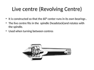
- 61. Live centre (Revolving Centre) • It is constructed so that the 60° center runs in its own bearings . • The live centre fits in the spindle (headstock)and rotates with the spindle. • Used when turning between centres
- 62. Centre in Headstock Spindle
- 63. Dead centre • Fits in the tailstock spindle, remains stationary while the work rotates on its point
- 64. Half Centre • A centre that is cut away almost to its point. It is often used in the tailstock for facing up to or for turning close to the end of the work.
- 67. Chucks
- 68. Chucks • Used extensively for holding work for machining operations – Work large or unusual shape • Most commonly used lathe chucks – Three-jaw universal – Four-jaw independent – Collet chuck
- 69. Three-jaw Universal Chuck • Holds round and hexagonal work • Grasps work quickly and accurate • Three jaws move simultaneously when adjusted by chuck Key
- 70. Four-Jaw Independent Chuck • Used to hold round, square, hexagonal, and irregularly shaped workpieces • Has four jaws – Each can be adjusted independently by chuck Key • Jaws can be reversed to hold work by inside diameter
- 71. Headstock Spindles Universal and independent chuck fitted to three types of headstock spindles 1. Threaded spindle nose – Screws on in a clockwise direction
- 72. 2. Tapered spindle nose Held by lock nut that tightens on chuck
- 73. 3. Cam-lock spindle nose • Held by tightening cam-locks using T-wrench • Chuck aligned by taper on spindle nose
- 74. Collet Chuck • Collet chuck is used to hold small Collet chuck is used to hold small workpieces. workpieces. • Used for high-precision work • Spring collets available to hold round, square, or hexagon-shaped workpieces • Each collet has range of only few thousandths of an inch over or under size stamped on collet
- 76. | Collet Chuck Special adapter fitted into taper of headstock spindle, and hollow draw bar having internal thread inserted in opposite end of headstock spindle. It draws collet into tapered adapter causing collet to tighten on workpiece.
- 78. Lathe Dogs /Carrier • A lathe dog ( lathe carrier) is a device that clamps around the workpiece and allows the rotary motion of the machine's spindle to be transmitted to the workpiece. • A carrier is most often used when turning between centers on a lathe.
- 79. Types of Lathe Dogs • Standard bent-tail lathe dog – Most commonly used for round workpieces – Available with square-head setscrews of headless setscrews • Straight-tail lathe dog – Driven by stud in driveplate – Used in precision turning
- 80. Types of Lathe Dogs • Safety clamp lathe dog – Used to hold variety of work – Wide range of adjustment • Clamp lathe dog – Wider range than others – Used on all shapes
- 81. Work Held Between Centre
- 82. Work Held Between Centres
- 83. Face plate • A faceplate is the basic workholding accessory for a lathe. It is a circular metal plate which fixes to the end of the lathe spindle. The workpiece is then clamped to the faceplate, typically using t-nuts in slots in the faceplate, or less commonly threaded holes in the faceplate itself.
- 84. Faceplate • Used to hold work too large or shaped so it cannot be held in chuck or between centers • Usually equipped with several slots to permit use of bolts to secure work
- 85. Drive plate • Provide the drive when turning between centres
- 86. Steady Rest / Fixed Steady • Used to support long work held in chuck or between lathe centers – Prevent springing • Located on and aligned by ways of the lathe • Positioned at any point along lathe bed • Three jaws tipped with plastic, bronze or rollers may be adjusted to support any work diameter with steadyrest capacity
- 87. Steady Rest
- 88. Steady Rest
- 89. Travelling Steady/Follower Rest • Mounted on saddle • Travels with carriage to prevent work from springing up and away from cutting tool – Cutting tool generally positioned just ahead of follower rest – Provide smooth bearing surface for two jaws of follower rest
- 92. Mandrel • Holds internally machined workpiece between centers so further machining operations are concentric with bore • Several types, but most common – Plain mandrel – Expanding mandrel – Gang mandrel – Stub mandrel
- 93. Plain Mandrel
- 95. Gang Mandrel
- 96. Stub Mandrel
- 97. Taper Turning • Tapers Uniform change in diameter of workpiece measured along its axis Provides rapid and accurate method of aligning machine parts and easy method of holding tools
- 98. Types of Tapers • Machine Tapers –Self-holding tapers –Steep or self-releasing tapers • Self-Holding Tapers • Remain in position because of the wedging action of the small taper angle • Steep Tapers • Used mainly for alignment of milling machine arbors and accessories
- 99. Types of Tapers • Standard Tapers • Used for drills, reamers, and lathe center shanks • Used for positioning and holding parts together
- 100. Method of Cutting Tapers • Using the tool angle • Setting the angle on the compound slide • Off set the tailstock • Using the taper turning attachment
- 101. Assignment 1. Do a presentation on any of the following method using any of the following in group of three: a. Video b. Picture c. Acting d. PowerPoint (picture and detail) e. movie
- 102. Assignment 2 • State and explain the process involve in knurling • Three method of holding work on the lathe • The procedure involve in facing and parallel turning • Four method of holding work on the drill press • Using the same presentation format
- 103. 103 Metric Tailstock Offset Calculations • If taper turned by offsetting tailstock, amount of offset O is calculated as follows: where D = large diameter d = small diameter l = length of taper L = length of work L x x 2 d - D Offset l
- 104. 104 Metric Taper Calculations d = small diameter k = unit length of taper l = total length of taper D = large diameter If know d, k, and l, D may be calculated. D equal to small dia + amount of taper. Amount of taper is equal to 1k, so total taper equals lk. D = d + total taper D = d + l/k
- 105. Using the compound Slide • Taper: L D D 2 tan 2 1
- 106. Taper Turning Calculation • Calculate tailstock offset required to turn a 1:30 taper X 60 mm long on a workpiece 300 mm long. The small diameter of tapered section is 20 mm.
- 107. question • Determine the angle at which the compound rest would be swiveled for cutting a taper on a workpiece having a length of 150 mm and outside diameter 80 mm. The smallest diameter on the tapered end of the rod should be 50 mm and the required length of the tapered portion is 80 mm.
- 108. Using the compound slide • Calculate the taper angle for the following: 50 105 20 40 l OL d D 40 100 20 50 l OL d D 60 120 30 60 l OL d D 10 : 1 40 100 20 ? K l OL d D