Radio Wave Propagation: Surface and space wave propagation, Sky wave through
Ionosphere. Pulse method for measuring height and electron concentration of
Ionospheric region; Chapman theory of layer formation, Ionospheric storm.
Modulation and Demodulation: Linear modulation - AM, SSB, DSB, and SSB
generation, PLL Circuit to generate linear modulated signals, low and high power
modulators, Exponential modulation- FM and PM, demodulation of AM, FM.
Broadcasting Transmitter: Transmitter classification, Elements of transmitter, AM and
FM transmitters, SSB transmitter, stabilized master oscillator, Frequency multipliers,
Mixer circuits, RF power amplifier, Pre-emphasis circuits, Transmitter performance-
carrier frequency requirements, audio frequency response, distortion, and signal to
distortion ratio.
Radio Receiver: Receiver classification, Elements of receiver, AM and FM receivers,
SSB receiver, Comparison of AM and FM receivers, Noise in receiver, AGC circuits, AFC
circuits, Noise limiters, Receiver sensitivity, Cross modulation, Spurious responses.
Representation of Random Signals and Noise in Communication System: Signal
Power and Spectral Representations, White noise, Thermal noise, PSDF of White
Signals. Input and Output Relationship for Random Signals and Noise Passed Through
a Linear Time Invariant System, Band Limited White Noise, ARC Filtering of White
Noise.
Course Contents
Elements of Digital Communication Systems: Elements of Digital Communication
Systems: Model of Digital Communication Systems, Digital Representation of Analog
Signal, Certain issues in Digital Transmission, Advantages of Digital Communication
Systems, Bandwidth-S/N tradeoff, Hartley Shannon Law.
Pulse Code Modulation: Pulse Code Modulation: PCM Generation and
Reconstruction, Quantization noise, Non uniform Quantization and Companding,
DPCM, Adaptive DPCM, DM and Adaptive DM. Noise in PCM and DM.
Digital Modulation Techniques: Digital Modulation Techniques: Introduction, ASK,
ASK Modulator, Coherent ASK Detector, Non-Coherent ASK Detector, FSK, Bandwidth
and Frequency Spectrum of FSK. Non coherent FSK Detector, Coherent FSK Detector,
FSK Detection Using PLL, BPSK, Coherent PSK Detection, QPSK, Differential PSK.
Line Coding: Techniques and Analysis.
Course Contents
Required Text Books:
B.P.Lathi, "Modern Digital & Analog Communication", Prison Books Pvt Ltd., 1989
Sanjay Sharma, "Communication Systems, Analog & Digital
Reference Books:
Simon Haykin, "Communication System", John Wiley & Sons, 4th Edition, 1991
K.Sam Shanmugam, "Digital & Analog Communication System", John Wiley & Sons
Course Objectives
To introduce with basic communication systems.
Various Amplitude modulation and demodulation systems
Various Angle modulation and demodulation systems
Basics of Noise theory and performance of various
receivers.
Design modulation and optimum demodulation and
detection methods for digital communications over an
AWGN channel.
Calculate the error rate performance for a number of
modulation schemes in AWGN environments
Course Outcomes
Understand basic elements of a communication system
Conduct analysis of baseband signals in time domain and in
frequency domain
Demonstrate understanding of various analog and digital
modulation and demodulation techniques.
Analyze the performance of modulation and demodulation
techniques in various transmission environments
Understand the importance of noise considerations in
communication systems.
Baseband and band-pass transmission techniques
 Detection & Estimation of signal
Communication Engineering concerned with the sending and receiving of signals
especially by means of electrical devices and electromagnetic waves.
Introduction
“Communication is the process of establishing connection or link between
two points for information exchange”
The examples of communication:
1. Ancient communication
2. Telegraph
3. Line telephony
4. Radio telephony
5. Radio telegraph
6. Point to point communication
7. Mobile communication
8. Computer communication
9. Radar communication
10. Television broadcasting
11. Radio telemetry
12. Radio aids to navigation
13. Radio aids to aircraft landing
Ancient Communications
Harkara Pigeons Fire and Smoke
Telegraph (1836)
Invention Of Telegraph: First Wireless Communication
Telephone (1876)
Invention Of Telephone ByAlexander Graham Bell: The Beginning of Electricity
Based Analog Communication
FM Radio(1933)
Mobile Phones (1983)
Mobile phone was first available
commercially in 1983. This indicated the
beginning of the large commercialization
of communication systems.
Contribution of Electronics in
Communication Devices
Lecture-01 analog and digital communication.pptx
Modern Communication System
Message: sounds (voice,
music), pictures, words,
codes, light, temperature,
pressure, etc.
Microphone, camera,
scanner, etc.
Information in
electrical signal/
modulating signal
Modulated signal
in RF range
(transmitted
through channel)
Modulator (Analog:
AM,FM.PM. Digital:
ASK, FSK, PSK, DM)
Information
source
Input
transducer
Transmitter
(Modulator)
Channel Receiver
Output
transducer
Noise
Reconstructed
electrical signal/
modulating signal
Modulated signal
in RF range
(received from
the channel)
Information in
the original form
Figure: Block diagram of a communication system
Information source:
• The message produced by the information source is not an electrical in
nature.
•Such as voice, music pictures, words, codes, lights, temperature etc.
•So we need transducer to convert from physical message to electrical signal.
Input transducer:
• It converts one form of energy into another form.
•It is used to convert physical message signal into time varying electrical signal.
Transmitter:
• Here, restriction of range of audio frequencies, amplification, and modulation
are achieved.
•Modulation is the superimposed of audio signal upon the high-frequency
carrier signal.
Modern Communication System
The channel and the Noise:
• It is the path through which the signal propagates from transmitter to
receiver.
•It may be a pair of wires, a coaxial cable, microwave links or radio waves or
space.
•In the channel, the signal gets distorted due to noise introduced in the
system.
•Noise signals are always random in character.
Receiver:
• It receives information from the modulated signal available at the transmission
channel.
•The main function of the receiver is to extract the original message signal from
the degraded version of the transmitted signal.
•Example: TV sets and Radio set are example for receivers
Destination:
• Destination is the final stage where electrical message signal is converted into
its original form, such as voice, message, etc.
•For example, in radio broadcasting, loudspeaker which works as a transducer.
Modern Communication System
Noise
Noise in a communication system is basically undesirable or unwanted
signals that get randomly added to the actual information carrying signal
Lecture-01 analog and digital communication.pptx
Bandwidth
The bandwidth is the frequency range over which an information signal is
transmitted
We may also say that bandwidth is the difference between the upper and
lower frequency limits of the signal.
Bandwidth
BW
0 Frequency, f
f1 =20 Hz f2 =15kHz
For example, the range of music signal is 20 Hz to 15 kHz, therefore, as
shown in the above figure, the bandwidth is
BW= f2-f1
BW=15000-20=14980 Hz.
Signal
A signal may be defined as the single valued function of time.
Speech: The band of frequencies required for the speech communication is 300 Hz
to 3100 Hz. This band is utilized for the commercial telephonic communication.
Music: Music signal is a bipolar signal and it requires a bandwidth of about 15 kHz.
Video: The bandwidth required for this video signal is 0 to 5 MHz.
Computer Data: The text transmitted by a computer is encoded using American
Standard Code for Information Interchange (ASCII)
ASCII code set
Communication Channels
Some important characteristics of a channel are:
Power required to achieve the desired S/N ratio.
Bandwidth of the channel.
Amplitude and phase response of channel.
Type of channel (linear or non-linear).
Effects of external interference on the channels.
Communication Channels
Telephone channels:
It is designed for providing service to voice signals such as telephones
Bandpass characteristics over 300 to 3400 Hz.
High signal to noise ratio of about 30 dB.
Approximately linear response.
Example of telephone channels: A common examples is twisted pair cable.
Advantages: It is quite cheaper.
Communication Channels
Co-axial cables:
It was initially developed as the backbone of analog telephone networks
A single cable would be used to carry more than 10,000 voice channels.
Two types of cables having 75 Ω and 50 Ω impedance are available.
Because of shielding, this cable has noise immunity.
It has large bandwidth and low losses
This cable is suitable for both point to point or point to multipoint
applications.
It expensive than twisted pair cable however, cheaper than optical fiber.
Repeaters are used after every 1 km to achieve data rates 8.5 Mb/s to
274 Mb/s
Advantages: co-axial cables provide higher immunity to electromagnetic
interference and higher bandwidth compared with twisted pair cables.
Communication Channels
Optical fiber cables:
An optical fiber is a very thin strand of plastic or glass that is used to
transmit messages via light.
It consist of an inner glass core. High bandwidth
Long distance
Immunity to electromagnetic interference required
It can transmit voice, video, and telemetry through LAN, computer
networks, or across long distances.
Advantages: Small size and light weight, easy availability and low cost, no
electrical or electromagnetic interference, large bandwidth.
Disadvantages: High initial cost, Maintenance and repairing cost, Jointing and test
procedures, Tensile stress, Fiber losses.
Communication Channels
Terrestrial microwave channel:
Terrestrial microwave channel requires a line of sight path between a
sender and a receiver.
Unidirectional
Repeaters are needed for long distance communication.
No adverse effects such as cable breakage etc.
Very high frequency microwave cannot penetrate walls
Less maintenance compared with cables.
Microwave waves are used for cellular networks, satellite and wireless
networks.
Disadvantages: Signal strength at the receiving antenna reduces due to multipath
reception.
Advantages: No cables needed, multiple channel available, wide bandwidth.
Communication Channels
Satellite channel:
A communication satellite is a microwave relay station.
Used to link two or more ground stations
It uses frequency range between 11 GHz and 14 GHz.
The message signal transmitted by the earth station to the satellite is
called as an uplink frequency.
It is amplified and down converted in frequency by the transponder.
The signal from satellite to earth is called downlink frequency.
It receives signal on one frequency (uplink=6 GHz) and transmits on
another frequency (downlink= 4 GHz).
Rotation match occurs at a height of 35,683 km at the equator.
Disadvantages: The cost of building and launching is very high.
Electronic communication systems
Classification: The electronic communication may be classified into three groups
based on
 whether the system is unidirectional or bidirectional.
Whether it uses an analog or digital information signal/modulating
signal.
Whether the system uses baseband transmission or use some kind of
modulation.
Fig. Classification of electronic communication system
Based on direction of communication
Based on the direction of communication, the communication systems are:
i. Simplex systems
ii. Half duplex systems
iii. Full duplex systems
Simplex systems: The information is communicated in only one direction such
as the radio and TV broadcasting.
Half duplex systems: The information is communicated in bi-direction but one
at a time such as walky-talky.
Full duplex systems: The information is communicated in both direction
simultaneously such as telephone.
Based on nature of information signal
Based on the nature of information signal the communication systems are:
Analog communication: The modulation systems or techniques in which one of
the characteristics (amplitude, phase or frequency) of the carrier is varied in
proportion with the instantaneous value of modulating signal is called as analog
modulation system.
Examples of analog modulation: Following are the examples of analog modulation
systems :
Amplitude modulation (AM)
Frequency modulation (FM)
Phase modulation (PM)
Pulse Amplitude Modulation (PAM)
Pulse Width Modulation (PWM)
Pulse Position Modulation (PPM)
Advantages of analog communication:
Transmitters and receivers are simple
Low bandwidth requirement
FDM (Frequency division multiplexing) can be used
Drawbacks of analog communication:
Noise affects the signal quality
It is not possible to separate noise and signal
Repeaters can not be used between transmitter and receiver
Coding is not possible
It is not suitable for the transmission of secret information
Applications:
Radio broadcasting (AM and FM)
TV broadcasting
Telephones
Digital communication
The modulation system or technique in which the transmitted signal is in the form of digital
pulses of constant amplitude, constant frequency and phase is called as digital modulation
system : The common applications are: Long distance, communication between earth and
space ships , Satellite communication, Military communication, Telephone systems, Data and
computer communications
Examples of digital modulation: Following are the examples of analog modulation systems :
Pulse code modulation (PCM)
delta modulation (DM)
Advantages of analog communication:
Reliable communication, less sensitivity to changes in environmental
conditions (such as temperature)
Easy multiplexing, easy signaling
Voice and data integration
Easy processing like encryption and compression
Integration of transmission and switching
FDM (Frequency division multiplexing) can be used
Drawbacks of Digital Communication:
The bit rates of digital systems are high . Therefore, they require a larger
channel bandwidth as compared to analog system .
Digital modulation needs synchronization in case of synchronous
modulation .
Classification based on technique of transmission
Baseband transmission systems: In baseband transmission systems, the baseband signals
(original information signals/modulating signal) are directly transmitted such as telephone
network
Limitations:
It cannot be used for free space communication because it gets suppressed after a
short distance.
Note: we can overcome this limitations using modulation
Based on the technique used for the signal transmission, we can categorize the
electronic communication system as under :
Baseband transmission system
Communication systems using modulation
Communication systems using modulation:
In the modulation process, two signals are used namely the modulating
signal and the carrier .
The modulating signal is nothing but the baseband signal or information
signal while the carrier is a high frequency sinusoidal signal .
What is modulation
Modulation is the process of varying one or more properties of a high frequency
periodic waveform, called the carrier signal, with a separate signal called
the modulation signal that typically contains information to be transmitted.
For example, the modulating signal might be an audio signal, a video signal etc.
Why do we need modulation
The modulation is necessary for the following reasons:
Reduction in the height of the antenna
Avoids mixing of signals
Increases the range of communication
Multiplexing is possible
Improve quality of reception
Reduction in the height of antenna : For the transmission of radio signals, the
antenna height must be a multiple of (λ/4). where λ is the wavelength (λ = c/f).
The minimum antenna height required to transmit a base-band signal of f = 10KHz
is calculated as follows:
Minimum antenna height = λ/4=C/4f=3×108 /(4×10×103)= 7500 m i.e. 7.5 km
The antenna of this height is practically impossible to install.
Now consider a modulated signal at f = 1MHz
The minimum height is given by=λ/4
=c/4f
=3×10⁸ /(4×10×106)
= 75 m
This size antenna can be installed practically.
Avoid mixing of signals
Different types of modulation systems
Amplitude modulation (AM)
The carrier is a sine wave frequency
The carrier frequency is much higher than the frequency of modulating signal.
Here, the information is contained in its amplitude variation.
The frequency of the carrier remains constant.
AM is used in radio and TV broadcasting applications.
Frequency modulation (FM)
The frequency of the carrier is changed in proportion with the amplitude of the
modulating signal.
The amplitude of the carrier remains constant.
FM is used for TV, sound, FM radio and police wireless transmission.
Phase modulation (PM)
The phase shift of the carrier is changed in proportion with the amplitude of the
modulating signal.
The amplitude of the carrier remains constant.
PM is used for generation of FM.
FM signal produced from PM signal is very stable.
The centre frequency called resting frequency is extremely stable.
Pulse analog modulation
The carrier is in the form of pulses instead of being a sinewave.
In PAM, the amplitude of the carrier is varied.
In PWM, the width of the carrier is varied.
In PPM, position of the pulses is varied with the amplitude of modulating signal.
Lecture-01 analog and digital communication.pptx
Digital Communication System
A/D Converter: Analog to Digital Converter
D/A Converter: Digital to Analog Converter
Lecture-01 analog and digital communication.pptx
Comparison of Analog and Digital Modulation
Limitation of communication systems
Physical limitations:
Bandwidth limitations
Measure of speed
The system ability to follow signal variations depends on the
transmission bandwidth
Available bandwidth determines the maximum signal speed.
Noise limitations
Unavoidable
The kinetic theory
Noise relative to information signal is measured in terms of
signal to noise ratio (SNR)
Compromise within:
Transmission time and power
SNR performance
Cost of equipments
Channel capacity
bandwidth

More Related Content

PDF
GSM Air Interface
PPTX
GSM. Global System for Mobile Communication.
PDF
Bit Error rate of QAM
PPT
Lecture 1 introduction to communication systems
PPTX
EC6503 TLWG - Waveform Distortion
PPTX
Wireless local loop
PPTX
Digital Modulation Techniques ppt
PDF
Modulation, Frequency Modulation, Phase Modulation, Amplitude Modulation
GSM Air Interface
GSM. Global System for Mobile Communication.
Bit Error rate of QAM
Lecture 1 introduction to communication systems
EC6503 TLWG - Waveform Distortion
Wireless local loop
Digital Modulation Techniques ppt
Modulation, Frequency Modulation, Phase Modulation, Amplitude Modulation

What's hot (20)

PPTX
M ary psk modulation
PPTX
PPT
Microwave Link Design - PTP Transmission
PPTX
Public Switched Telephone Network
PPT
How PSTN phone works?
PPT
Different types of Modulation Techniques
PPTX
3.4_OOK systems – ASK, FSK, PSK, BPSK, QPSK, applications of Data communicati...
PDF
Mobile Communication
PDF
Multiplexing, Frequency Division Multiplexing (FDM), Time Division Multiplexi...
PDF
Lect 11.regenerative repeaters
PDF
1 introducción- Propagación de Ondas
PPTX
Types of klystron Amplifier
PPT
PPTX
Small scale fading and multipath measurements
PDF
FUNDAMENTALS OF MICROWAVE RADIO COMMUNICATION FOR IP AND TDM
PDF
network layer description and features including protocols advantages
PDF
IEEE 802.16 Standard
PPTX
Broadband isdn
PPTX
Digital signal transmission in ofc
PPTX
Transmission system used for optical fibers
M ary psk modulation
Microwave Link Design - PTP Transmission
Public Switched Telephone Network
How PSTN phone works?
Different types of Modulation Techniques
3.4_OOK systems – ASK, FSK, PSK, BPSK, QPSK, applications of Data communicati...
Mobile Communication
Multiplexing, Frequency Division Multiplexing (FDM), Time Division Multiplexi...
Lect 11.regenerative repeaters
1 introducción- Propagación de Ondas
Types of klystron Amplifier
Small scale fading and multipath measurements
FUNDAMENTALS OF MICROWAVE RADIO COMMUNICATION FOR IP AND TDM
network layer description and features including protocols advantages
IEEE 802.16 Standard
Broadband isdn
Digital signal transmission in ofc
Transmission system used for optical fibers
Ad

Similar to Lecture-01 analog and digital communication.pptx (20)

PPT
Lec 1 Telecomistory of telecommunication engineering.ppt
PPTX
embedded systems
PPTX
CS_Lec#1.pptx
PPTX
Communication_System_presentation_Slides.pptx
PPTX
UNIT-4 modified 28082022.pptx
PDF
Introduction and History of Telecommunication
PPTX
Communication systems design for the CM.pptx
PPTX
Communication system 1 chapter 1 ppt
PDF
Lecture 1 : introduction to comm theory.pdf
PPTX
Introduction to Communication Systems.pptx
PPTX
communication system basics slide ppt classnotes
PPT
Comm introduction
PPT
Comm introduction
PDF
Communication Systems Lecture 1 Intro pdf.
PPT
1 . introduction to communication system
PPTX
Introduction to Electronic Communication
PPTX
AnalogDigitalCommunicationRecall_notes.pptx
PPT
Communication systems v1
PDF
Comunicaciones analógicas - Introduccion
Lec 1 Telecomistory of telecommunication engineering.ppt
embedded systems
CS_Lec#1.pptx
Communication_System_presentation_Slides.pptx
UNIT-4 modified 28082022.pptx
Introduction and History of Telecommunication
Communication systems design for the CM.pptx
Communication system 1 chapter 1 ppt
Lecture 1 : introduction to comm theory.pdf
Introduction to Communication Systems.pptx
communication system basics slide ppt classnotes
Comm introduction
Comm introduction
Communication Systems Lecture 1 Intro pdf.
1 . introduction to communication system
Introduction to Electronic Communication
AnalogDigitalCommunicationRecall_notes.pptx
Communication systems v1
Comunicaciones analógicas - Introduccion
Ad

Recently uploaded (20)

PPTX
wireless networks, mobile computing.pptx
PDF
Unit I -OPERATING SYSTEMS_SRM_KATTANKULATHUR.pptx.pdf
PDF
MLpara ingenieira CIVIL, meca Y AMBIENTAL
PDF
UEFA_Embodied_Carbon_Emissions_Football_Infrastructure.pdf
PDF
Soil Improvement Techniques Note - Rabbi
PPTX
ai_satellite_crop_management_20250815030350.pptx
PDF
distributed database system" (DDBS) is often used to refer to both the distri...
PDF
UEFA_Carbon_Footprint_Calculator_Methology_2.0.pdf
PDF
Unit1 - AIML Chapter 1 concept and ethics
PDF
Influence of Green Infrastructure on Residents’ Endorsement of the New Ecolog...
PPTX
Module 8- Technological and Communication Skills.pptx
PPTX
Principal presentation for NAAC (1).pptx
PPTX
Graph Data Structures with Types, Traversals, Connectivity, and Real-Life App...
PDF
Implantable Drug Delivery System_NDDS_BPHARMACY__SEM VII_PCI .pdf
PDF
Computer System Architecture 3rd Edition-M Morris Mano.pdf
PDF
Prof. Dr. KAYIHURA A. SILAS MUNYANEZA, PhD..pdf
PDF
Abrasive, erosive and cavitation wear.pdf
PPTX
Management Information system : MIS-e-Business Systems.pptx
PPTX
"Array and Linked List in Data Structures with Types, Operations, Implementat...
PPTX
Petroleum Refining & Petrochemicals.pptx
wireless networks, mobile computing.pptx
Unit I -OPERATING SYSTEMS_SRM_KATTANKULATHUR.pptx.pdf
MLpara ingenieira CIVIL, meca Y AMBIENTAL
UEFA_Embodied_Carbon_Emissions_Football_Infrastructure.pdf
Soil Improvement Techniques Note - Rabbi
ai_satellite_crop_management_20250815030350.pptx
distributed database system" (DDBS) is often used to refer to both the distri...
UEFA_Carbon_Footprint_Calculator_Methology_2.0.pdf
Unit1 - AIML Chapter 1 concept and ethics
Influence of Green Infrastructure on Residents’ Endorsement of the New Ecolog...
Module 8- Technological and Communication Skills.pptx
Principal presentation for NAAC (1).pptx
Graph Data Structures with Types, Traversals, Connectivity, and Real-Life App...
Implantable Drug Delivery System_NDDS_BPHARMACY__SEM VII_PCI .pdf
Computer System Architecture 3rd Edition-M Morris Mano.pdf
Prof. Dr. KAYIHURA A. SILAS MUNYANEZA, PhD..pdf
Abrasive, erosive and cavitation wear.pdf
Management Information system : MIS-e-Business Systems.pptx
"Array and Linked List in Data Structures with Types, Operations, Implementat...
Petroleum Refining & Petrochemicals.pptx

Lecture-01 analog and digital communication.pptx

  • 1. Radio Wave Propagation: Surface and space wave propagation, Sky wave through Ionosphere. Pulse method for measuring height and electron concentration of Ionospheric region; Chapman theory of layer formation, Ionospheric storm. Modulation and Demodulation: Linear modulation - AM, SSB, DSB, and SSB generation, PLL Circuit to generate linear modulated signals, low and high power modulators, Exponential modulation- FM and PM, demodulation of AM, FM. Broadcasting Transmitter: Transmitter classification, Elements of transmitter, AM and FM transmitters, SSB transmitter, stabilized master oscillator, Frequency multipliers, Mixer circuits, RF power amplifier, Pre-emphasis circuits, Transmitter performance- carrier frequency requirements, audio frequency response, distortion, and signal to distortion ratio. Radio Receiver: Receiver classification, Elements of receiver, AM and FM receivers, SSB receiver, Comparison of AM and FM receivers, Noise in receiver, AGC circuits, AFC circuits, Noise limiters, Receiver sensitivity, Cross modulation, Spurious responses. Representation of Random Signals and Noise in Communication System: Signal Power and Spectral Representations, White noise, Thermal noise, PSDF of White Signals. Input and Output Relationship for Random Signals and Noise Passed Through a Linear Time Invariant System, Band Limited White Noise, ARC Filtering of White Noise. Course Contents
  • 2. Elements of Digital Communication Systems: Elements of Digital Communication Systems: Model of Digital Communication Systems, Digital Representation of Analog Signal, Certain issues in Digital Transmission, Advantages of Digital Communication Systems, Bandwidth-S/N tradeoff, Hartley Shannon Law. Pulse Code Modulation: Pulse Code Modulation: PCM Generation and Reconstruction, Quantization noise, Non uniform Quantization and Companding, DPCM, Adaptive DPCM, DM and Adaptive DM. Noise in PCM and DM. Digital Modulation Techniques: Digital Modulation Techniques: Introduction, ASK, ASK Modulator, Coherent ASK Detector, Non-Coherent ASK Detector, FSK, Bandwidth and Frequency Spectrum of FSK. Non coherent FSK Detector, Coherent FSK Detector, FSK Detection Using PLL, BPSK, Coherent PSK Detection, QPSK, Differential PSK. Line Coding: Techniques and Analysis. Course Contents Required Text Books: B.P.Lathi, "Modern Digital & Analog Communication", Prison Books Pvt Ltd., 1989 Sanjay Sharma, "Communication Systems, Analog & Digital Reference Books: Simon Haykin, "Communication System", John Wiley & Sons, 4th Edition, 1991 K.Sam Shanmugam, "Digital & Analog Communication System", John Wiley & Sons
  • 3. Course Objectives To introduce with basic communication systems. Various Amplitude modulation and demodulation systems Various Angle modulation and demodulation systems Basics of Noise theory and performance of various receivers. Design modulation and optimum demodulation and detection methods for digital communications over an AWGN channel. Calculate the error rate performance for a number of modulation schemes in AWGN environments
  • 4. Course Outcomes Understand basic elements of a communication system Conduct analysis of baseband signals in time domain and in frequency domain Demonstrate understanding of various analog and digital modulation and demodulation techniques. Analyze the performance of modulation and demodulation techniques in various transmission environments Understand the importance of noise considerations in communication systems. Baseband and band-pass transmission techniques  Detection & Estimation of signal
  • 5. Communication Engineering concerned with the sending and receiving of signals especially by means of electrical devices and electromagnetic waves.
  • 6. Introduction “Communication is the process of establishing connection or link between two points for information exchange” The examples of communication: 1. Ancient communication 2. Telegraph 3. Line telephony 4. Radio telephony 5. Radio telegraph 6. Point to point communication 7. Mobile communication 8. Computer communication 9. Radar communication 10. Television broadcasting 11. Radio telemetry 12. Radio aids to navigation 13. Radio aids to aircraft landing
  • 8. Telegraph (1836) Invention Of Telegraph: First Wireless Communication
  • 9. Telephone (1876) Invention Of Telephone ByAlexander Graham Bell: The Beginning of Electricity Based Analog Communication
  • 11. Mobile Phones (1983) Mobile phone was first available commercially in 1983. This indicated the beginning of the large commercialization of communication systems.
  • 12. Contribution of Electronics in Communication Devices
  • 14. Modern Communication System Message: sounds (voice, music), pictures, words, codes, light, temperature, pressure, etc. Microphone, camera, scanner, etc. Information in electrical signal/ modulating signal Modulated signal in RF range (transmitted through channel) Modulator (Analog: AM,FM.PM. Digital: ASK, FSK, PSK, DM) Information source Input transducer Transmitter (Modulator) Channel Receiver Output transducer Noise Reconstructed electrical signal/ modulating signal Modulated signal in RF range (received from the channel) Information in the original form Figure: Block diagram of a communication system Information source: • The message produced by the information source is not an electrical in nature. •Such as voice, music pictures, words, codes, lights, temperature etc. •So we need transducer to convert from physical message to electrical signal. Input transducer: • It converts one form of energy into another form. •It is used to convert physical message signal into time varying electrical signal. Transmitter: • Here, restriction of range of audio frequencies, amplification, and modulation are achieved. •Modulation is the superimposed of audio signal upon the high-frequency carrier signal.
  • 15. Modern Communication System The channel and the Noise: • It is the path through which the signal propagates from transmitter to receiver. •It may be a pair of wires, a coaxial cable, microwave links or radio waves or space. •In the channel, the signal gets distorted due to noise introduced in the system. •Noise signals are always random in character. Receiver: • It receives information from the modulated signal available at the transmission channel. •The main function of the receiver is to extract the original message signal from the degraded version of the transmitted signal. •Example: TV sets and Radio set are example for receivers Destination: • Destination is the final stage where electrical message signal is converted into its original form, such as voice, message, etc. •For example, in radio broadcasting, loudspeaker which works as a transducer.
  • 18. Noise Noise in a communication system is basically undesirable or unwanted signals that get randomly added to the actual information carrying signal
  • 20. Bandwidth The bandwidth is the frequency range over which an information signal is transmitted We may also say that bandwidth is the difference between the upper and lower frequency limits of the signal. Bandwidth BW 0 Frequency, f f1 =20 Hz f2 =15kHz For example, the range of music signal is 20 Hz to 15 kHz, therefore, as shown in the above figure, the bandwidth is BW= f2-f1 BW=15000-20=14980 Hz.
  • 21. Signal A signal may be defined as the single valued function of time. Speech: The band of frequencies required for the speech communication is 300 Hz to 3100 Hz. This band is utilized for the commercial telephonic communication. Music: Music signal is a bipolar signal and it requires a bandwidth of about 15 kHz. Video: The bandwidth required for this video signal is 0 to 5 MHz. Computer Data: The text transmitted by a computer is encoded using American Standard Code for Information Interchange (ASCII)
  • 23. Communication Channels Some important characteristics of a channel are: Power required to achieve the desired S/N ratio. Bandwidth of the channel. Amplitude and phase response of channel. Type of channel (linear or non-linear). Effects of external interference on the channels.
  • 24. Communication Channels Telephone channels: It is designed for providing service to voice signals such as telephones Bandpass characteristics over 300 to 3400 Hz. High signal to noise ratio of about 30 dB. Approximately linear response. Example of telephone channels: A common examples is twisted pair cable. Advantages: It is quite cheaper.
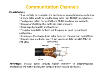
  • 25. Communication Channels Co-axial cables: It was initially developed as the backbone of analog telephone networks A single cable would be used to carry more than 10,000 voice channels. Two types of cables having 75 Ω and 50 Ω impedance are available. Because of shielding, this cable has noise immunity. It has large bandwidth and low losses This cable is suitable for both point to point or point to multipoint applications. It expensive than twisted pair cable however, cheaper than optical fiber. Repeaters are used after every 1 km to achieve data rates 8.5 Mb/s to 274 Mb/s Advantages: co-axial cables provide higher immunity to electromagnetic interference and higher bandwidth compared with twisted pair cables.
  • 26. Communication Channels Optical fiber cables: An optical fiber is a very thin strand of plastic or glass that is used to transmit messages via light. It consist of an inner glass core. High bandwidth Long distance Immunity to electromagnetic interference required It can transmit voice, video, and telemetry through LAN, computer networks, or across long distances. Advantages: Small size and light weight, easy availability and low cost, no electrical or electromagnetic interference, large bandwidth. Disadvantages: High initial cost, Maintenance and repairing cost, Jointing and test procedures, Tensile stress, Fiber losses.
  • 27. Communication Channels Terrestrial microwave channel: Terrestrial microwave channel requires a line of sight path between a sender and a receiver. Unidirectional Repeaters are needed for long distance communication. No adverse effects such as cable breakage etc. Very high frequency microwave cannot penetrate walls Less maintenance compared with cables. Microwave waves are used for cellular networks, satellite and wireless networks. Disadvantages: Signal strength at the receiving antenna reduces due to multipath reception. Advantages: No cables needed, multiple channel available, wide bandwidth.
  • 28. Communication Channels Satellite channel: A communication satellite is a microwave relay station. Used to link two or more ground stations It uses frequency range between 11 GHz and 14 GHz. The message signal transmitted by the earth station to the satellite is called as an uplink frequency. It is amplified and down converted in frequency by the transponder. The signal from satellite to earth is called downlink frequency. It receives signal on one frequency (uplink=6 GHz) and transmits on another frequency (downlink= 4 GHz). Rotation match occurs at a height of 35,683 km at the equator. Disadvantages: The cost of building and launching is very high.
  • 29. Electronic communication systems Classification: The electronic communication may be classified into three groups based on  whether the system is unidirectional or bidirectional. Whether it uses an analog or digital information signal/modulating signal. Whether the system uses baseband transmission or use some kind of modulation. Fig. Classification of electronic communication system
  • 30. Based on direction of communication Based on the direction of communication, the communication systems are: i. Simplex systems ii. Half duplex systems iii. Full duplex systems Simplex systems: The information is communicated in only one direction such as the radio and TV broadcasting. Half duplex systems: The information is communicated in bi-direction but one at a time such as walky-talky. Full duplex systems: The information is communicated in both direction simultaneously such as telephone.
  • 31. Based on nature of information signal Based on the nature of information signal the communication systems are: Analog communication: The modulation systems or techniques in which one of the characteristics (amplitude, phase or frequency) of the carrier is varied in proportion with the instantaneous value of modulating signal is called as analog modulation system.
  • 32. Examples of analog modulation: Following are the examples of analog modulation systems : Amplitude modulation (AM) Frequency modulation (FM) Phase modulation (PM) Pulse Amplitude Modulation (PAM) Pulse Width Modulation (PWM) Pulse Position Modulation (PPM) Advantages of analog communication: Transmitters and receivers are simple Low bandwidth requirement FDM (Frequency division multiplexing) can be used Drawbacks of analog communication: Noise affects the signal quality It is not possible to separate noise and signal Repeaters can not be used between transmitter and receiver Coding is not possible It is not suitable for the transmission of secret information Applications: Radio broadcasting (AM and FM) TV broadcasting Telephones
  • 33. Digital communication The modulation system or technique in which the transmitted signal is in the form of digital pulses of constant amplitude, constant frequency and phase is called as digital modulation system : The common applications are: Long distance, communication between earth and space ships , Satellite communication, Military communication, Telephone systems, Data and computer communications Examples of digital modulation: Following are the examples of analog modulation systems : Pulse code modulation (PCM) delta modulation (DM) Advantages of analog communication: Reliable communication, less sensitivity to changes in environmental conditions (such as temperature) Easy multiplexing, easy signaling Voice and data integration Easy processing like encryption and compression Integration of transmission and switching FDM (Frequency division multiplexing) can be used Drawbacks of Digital Communication: The bit rates of digital systems are high . Therefore, they require a larger channel bandwidth as compared to analog system . Digital modulation needs synchronization in case of synchronous modulation .
  • 34. Classification based on technique of transmission Baseband transmission systems: In baseband transmission systems, the baseband signals (original information signals/modulating signal) are directly transmitted such as telephone network Limitations: It cannot be used for free space communication because it gets suppressed after a short distance. Note: we can overcome this limitations using modulation Based on the technique used for the signal transmission, we can categorize the electronic communication system as under : Baseband transmission system Communication systems using modulation Communication systems using modulation: In the modulation process, two signals are used namely the modulating signal and the carrier . The modulating signal is nothing but the baseband signal or information signal while the carrier is a high frequency sinusoidal signal .
  • 35. What is modulation Modulation is the process of varying one or more properties of a high frequency periodic waveform, called the carrier signal, with a separate signal called the modulation signal that typically contains information to be transmitted. For example, the modulating signal might be an audio signal, a video signal etc.
  • 36. Why do we need modulation The modulation is necessary for the following reasons: Reduction in the height of the antenna Avoids mixing of signals Increases the range of communication Multiplexing is possible Improve quality of reception Reduction in the height of antenna : For the transmission of radio signals, the antenna height must be a multiple of (λ/4). where λ is the wavelength (λ = c/f). The minimum antenna height required to transmit a base-band signal of f = 10KHz is calculated as follows: Minimum antenna height = λ/4=C/4f=3×108 /(4×10×103)= 7500 m i.e. 7.5 km The antenna of this height is practically impossible to install. Now consider a modulated signal at f = 1MHz The minimum height is given by=λ/4 =c/4f =3×10⁸ /(4×10×106) = 75 m This size antenna can be installed practically.
  • 37. Avoid mixing of signals
  • 38. Different types of modulation systems
  • 39. Amplitude modulation (AM) The carrier is a sine wave frequency The carrier frequency is much higher than the frequency of modulating signal. Here, the information is contained in its amplitude variation. The frequency of the carrier remains constant. AM is used in radio and TV broadcasting applications.
  • 40. Frequency modulation (FM) The frequency of the carrier is changed in proportion with the amplitude of the modulating signal. The amplitude of the carrier remains constant. FM is used for TV, sound, FM radio and police wireless transmission.
  • 41. Phase modulation (PM) The phase shift of the carrier is changed in proportion with the amplitude of the modulating signal. The amplitude of the carrier remains constant. PM is used for generation of FM. FM signal produced from PM signal is very stable. The centre frequency called resting frequency is extremely stable.
  • 42. Pulse analog modulation The carrier is in the form of pulses instead of being a sinewave. In PAM, the amplitude of the carrier is varied. In PWM, the width of the carrier is varied. In PPM, position of the pulses is varied with the amplitude of modulating signal.
  • 44. Digital Communication System A/D Converter: Analog to Digital Converter D/A Converter: Digital to Analog Converter
  • 47. Comparison of Analog and Digital Modulation
  • 48. Limitation of communication systems Physical limitations: Bandwidth limitations Measure of speed The system ability to follow signal variations depends on the transmission bandwidth Available bandwidth determines the maximum signal speed. Noise limitations Unavoidable The kinetic theory Noise relative to information signal is measured in terms of signal to noise ratio (SNR) Compromise within: Transmission time and power SNR performance Cost of equipments Channel capacity bandwidth