SlideShare a Scribd company logo
Data Link Layer
Part 1
1
1. Introduction
• In this lecture we look at algorithms for achieving reliable,
efficient communication of whole units of information called
frames (rather than individual bits, as in the physical layer)
between two adjacent machines.
• By adjacent, we mean that the two machines are connected
by a communication channel.
• The data link layer uses the services of the physical layer to
send and receive bits over communication channels.
2
2. Data Link Layer Design Issues
• The following functions need to be incorporated during data
link layer protocol design:
– Providing a well-defined service interface to the network layer.
– Error control: Dealing with transmission errors.
– Flow control: Regulating the flow of data so that slow receivers are not
swamped by fast senders.
• To accomplish these goals, the data link layer takes the
packets it gets from the network layer and encapsulates them
into frames for transmission.
• Each frame contains a frame header, a payload field for
holding the packet, and a frame trailer.
3
2. Data Link Layer Design Issues
4
2.1Services Provided to the Network Layer
• The data link layer transfers data from the network layer on
the source machine to the network layer on the destination
machine.
5
2.1 Services Provided to the Network Layer
• The data link layer can be designed to offer different services.
• The actual services that are offered vary from protocol to
protocol.
• Three possibilities of services are:
– Unacknowledged connectionless service.
– Acknowledged connectionless service.
– Acknowledged connection-oriented service.
6
2.1 Services Provided to the Network Layer
• Unacknowledged connectionless service.
– Unacknowledged connectionless service consists of having the source
machine send independent frames to the destination machine without
having the destination machine acknowledge them.
– Ethernet is a good example of a data link layer that provides this
class of service.
– No logical connection is established beforehand or released
afterward.
– If a frame is lost due to noise on the line, no attempt is made to
detect the loss or recover from it in the data link layer.
– This class of service is appropriate when the error rate is very low, so
recovery is left to higher layers.
– It is also appropriate for real-time traffic, such as voice, in which late
data are worse than bad data.
7
2.1 Services Provided to the Network Layer
• Acknowledged connectionless service.
– When this service is offered, there are still no logical connections
used, but each frame sent is individually acknowledged.
– In this way, the sender knows whether a frame has arrived correctly or
been lost.
– If it has not arrived within a specified time interval, it can be sent
again.
– This service is useful over unreliable channels, such as wireless
systems. 802.11 (WiFi) is a good example of this class of service.
8
2.1 Services Provided to the Network Layer
• Acknowledged connection-oriented
service.
– With this service, the source and destination machines establish a
connection before any data are transferred.
– Each frame sent over the connection is numbered, and the data link
layer guarantees that each frame sent is indeed received.
– Guarantees that all frames are received in the right order.
– It is appropriate over long, unreliable links such as a satellite channel
or a long-distance telephone circuit.
9
2.2 Error Detection and Correction
• For unacknowledged connectionless service it might be fine if
the sender just kept outputting frames without regard to
whether they were arriving properly.
• But for reliable, connection-oriented service it would not be
fine at all.
• Sender can send either send:
– a positive or negative acknowledgement for correctly received frames
– indicates correctly received frames
– or negative acknowledgement for frames not received - indicates
incorrectly received frames – frames needs to be retransmitted
10
2.2 Error Detection and Correction
• There are two basic strategies for dealing with errors:
– Error correction:
• Include enough redundant information to enable the receiver to deduce what the
transmitted data must have been.
• This is also known as Forward Correction (FEC).
• Used on noisy channels such as wireless links that may make many errors
• FEC is used on unreliable/noisy channels because retransmissions are just as likely
to be in error as the first transmission e.g wireless channels
– Error detection:
• Include only enough redundancy to allow the receiver to deduce that an error has
occurred (but not which error) and have it request a retransmission.
• Used on channels that are highly reliable such as fiber
11
3.Elementary Data Link Protocols
• Data Link Layer protocols are responsible to ensure and
confirm that the bits and bytes that are received are identical
to the bits and bytes being transferred from the sender.
• Data Link Layer protocols refers a set of specifications that
are used for implementation of data link layer
• Elementary data link protocols refer to basic data link
protocols.
• We look at the basic data link protocols before we look at
more advanced ones.
• We will look at simplex protocols here
12
3.Elementary Data Link Protocols
• Some of the data link layer process and the physical layer
process run on dedicated hardware called a NIC (Network
Interface Card).
• The rest of the link layer process and the network layer
process run on the main CPU as part of the operating system,
with the software for the link layer process often taking the
form of a device driver.
13
3. Elementary Data Link Protocols
Continued 
Some definitions needed in the protocols to follow. These are located in
the file protocol.h.
14
(1.2)Protocol
Definitions
(ctd.)
Some definitions needed in
the protocols to follow. These
are located in the file
protocol.h.
15
3. Elementary Data Link Protocols
• A frame is composed of four fields: kind, seq, ack, and info
• The first three of which contain control information and the
last of which may contain actual data to be transferred. These
control fields are collectively called the frame header.
• The kind field tells whether there are any data in the frame,
because some of the protocols distinguish frames containing
only control information from those containing data as well.
• The seq and ack fields are used for sequence numbers
and acknowledgements, respectively; their use will be
described in more detail later.
• The info field of a data frame contains a single packet; the info
field of a control frame is not used.
16
3. Elementary Data Link Protocols
• Initially, the receiver has nothing to do. It just sits around
waiting for something to happen.
• In the example protocols we will indicate that the data link
layer is waiting for something to happen by the procedure call
wait for event(&event).
• This procedure only returns when something has happened
(e.g., a frame has arrived).
• Upon return, the variable event tells what happened.
• The set of possible events differs for the various protocols
depending on the complexity of the protocol
17
3. Elementary Data Link Protocols
• When a frame arrives at the receiver, the checksum is
recomputed.
• If the checksum in the frame is incorrect (i.e., there was a
transmission error), the data link layer is so informed (event =
cksum err).
• If the inbound frame arrived undamaged, the data link layer is
also informed (event = frame arrival) so that it can acquire the
frame for inspection using from physical layer.
• As soon as the receiving data link layer has acquired an
undamaged frame, it checks the control information in the
header, and, if everything is all right, passes the packet
portion to the network layer.
18
3. Elementary Data Link Protocols
• The procedures to network layer and from network layer are
used by the data link layer to pass packets to the network
layer and accept packets from the network layer, respectively.
• Note that from physical layer and to physical layer pass
frames between the data link layer and the physical layer.
• In other words, to network layer and from network layer deal
with the interface between layers 2 and 3, whereas from
physical layer and to physical layer deal with the interface
between layers 1 and 2.
19
3. Elementary Data Link Protocols
• In most of the protocols, we assume that the channel is
unreliable and loses entire frames upon occasion.
• To be able to recover from such calamities, the sending data
link layer must start an internal timer or clock whenever it
sends a frame.
• If no reply has been received within a certain predetermined
time interval, the clock times out and the data link layer
receives an interrupt signal.
• In our protocols this is handled by allowing the procedure
wait for event to return event = timeout.
• The procedures start timer and stop timer turn the timer on
and off, respectively.
20
3. Elementary Data Link Protocols
• Timeout events are possible only when the timer is running
and before stop timer is called.
• It is explicitly permitted to call start timer while the timer is
running; such a call simply resets the clock to cause the next
timeout after a full timer interval has elapsed (unless it is
reset or turned off).
21
3. Elementary Data Link Protocols
• The procedures enable network layer and disable network
layer are used in the more sophisticated protocols.
• When the data link layer enables the network layer, the
network layer is then permitted to interrupt when it has a
packet to be sent.
• We indicate this with event = network layer ready.
• When the network layer is disabled, it may not cause such
events.
• By being careful about when it enables and disables its
network layer, the data link layer can prevent the network
layer from swamping it with packets for which it has no buffer
space.
22
3. Elementary Data Link Protocols
• Frame sequence numbers are always in the range 0 to MAX
SEQ (inclusive), where MAX SEQ is different for the different
protocols.
• It is frequently necessary to advance a sequence number by 1
circularly (i.e., MAX SEQ is followed by 0).
• The macro inc performs this incrementing. It has been defined
as a macro because it is used in-line within the critical path.
23
3. Elementary Data Link Protocols
• There are three types of elementary data link protocols:
– An Unrestricted Simplex Protocol
– A Simplex Stop-and-Wait Protocol
– A Simplex Protocol for a Noisy Channel
• They are all simplex protocols - data is transmitted in one
direction only
24
3.1 An Unrestricted Simplex Protocol
• This protocol assumes nothing ever goes wrong
• Data are transmitted in one direction only.
• Both the transmitting and receiving network layers are always
ready.
• Infinite buffer space is available.
• And best of all, the communication channel between the data
link layers never damages or loses frames.
• No sequence numbers or acknowledgements are used here,
so MAX SEQ is not needed.
• The only event type possible is frame arrival (i.e., the arrival
of an undamaged frame).
25
3.1 An Unrestricted Simplex Protocol
• The protocol consists of two distinct procedures, a sender and
a receiver.
• The sender runs in the data link layer of the source machine,
and the receiver runs in the data link layer of the destination
machine.
26
Unrestricted
Simplex
Protocol
27
3.1 An Unrestricted Simplex Protocol
• The sender is in an infinite while loop just pumping data out
onto the line as fast as it can.
• The body of the loop consists of three actions:
– go fetch a packet from the (always obliging) network layer,
– construct an outbound frame using the variables,
– and send the frame on its way.
• Only the info field of the frame is used by this protocol,
because the other fields have to do with error and flow
control and there are no errors or flow control restrictions
here.
28
3.1 An Unrestricted Simplex Protocol
• The receiver is equally simple.
• Initially, it waits for something to happen, the only possibility
being the arrival of an undamaged frame.
• Eventually, the frame arrives and the procedure wait for event
returns, with event set to frame arrival (which is ignored
anyway).
• The call to from physical layer removes the newly arrived
frame from the hardware buffer and puts it in the variable r,
where the receiver code can get at it.
• Finally, the data portion is passed on to the network layer, and
the data link layer settles back to wait for the next frame,
effectively suspending itself until the frame arrives.
29
3.2 A Simplex Stop-and-Wait Protocol
• Now we will tackle the problem of preventing the sender from
flooding the receiver with frames faster than the latter is able
to process them because of limited buffer space -> Flow
control.
• Solution to this problem is to have the receiver provide
feedback to the sender.
• After having passed a packet to its network layer, the receiver
sends a little dummy frame back to the sender which, in
effect, gives the sender permission to transmit the next
frame.
30
3.2 A Simplex Stop-and-Wait Protocol
• After having sent a frame, the sender is required by the
protocol to bide its time until the little dummy (i.e.,
acknowledgement) frame arrives.
• This delay is a simple example of a flow control protocol.
• Protocols in which the sender sends one frame and then
waits for an acknowledgement before proceeding are called
stop-and-wait.
31
(3.2)
Simplex
Stop-and-
Wait
Protocol
32
3.2 A Simplex Stop-and-Wait Protocol
• As in protocol 1, the sender starts out by fetching a packet
from the network layer, using it to construct a frame, and
sending it on its way.
• But now, unlike in protocol 1, the sender must wait until an
acknowledgement frame arrives before looping back and
fetching the next packet from the network layer.
• The sending data link layer need not even inspect the
incoming frame as there is only one possibility.
• The incoming frame is always an acknowledgement.
33
3.2 A Simplex Stop-and-Wait Protocol
• The only difference between receiver1 and receiver2 is that
after delivering a packet to the network layer, receiver2 sends
an acknowledgement frame back to the sender before
entering the wait loop again.
34
3.3 A Simplex Protocol for a Noisy Channel
• Now let us consider the normal situation of a communication
channel that makes errors.
• Frames may be either damaged or lost completely.
• However, we assume that if a frame is damaged in transit, the
receiver hardware will detect this
• Protocols in which the sender waits for a positive
acknowledgement before advancing to the next data item are
often called ARQ (Automatic Repeat reQuest) or PAR
(Positive Acknowledgement with Retransmission).
35
A Simplex Protocol for a Noisy Channel
A positive
acknowledgement with
retransmission protocol.
Continued  36
A Simplex Protocol for a Noisy Channel
A positive acknowledgement with retransmission protocol.
37
3.3 A Simplex Protocol for a Noisy Channel
• Protocol 3 differs from its predecessors in that both sender
and receiver have a variable whose value is remembered
while the data link layer is in the wait state.
• The sender remembers the sequence number of the next
frame to send in next frame to send; the receiver remembers
the sequence number of the next frame expected in frame
expected.
• After transmitting a frame, the sender starts the timer
running.
38
3.3 A Simplex Protocol for a Noisy Channel
• If it was already running, it will be reset to allow another full
timer interval.
• Only when that interval has elapsed is it safe to assume that
either the transmitted frame or its acknowledgement has
been lost, and to send a duplicate frame.
• After transmitting a frame and starting the timer, the sender
waits for something exciting to happen.
• Only three possibilities exist:
– an acknowledgement frame arrives undamaged,
– a damaged acknowledgement frame staggers in,
– or the timer expires.
39
3.3 A Simplex Protocol for a Noisy Channel
• If a valid acknowledgement comes in, the sender fetches the
next packet from its network layer and puts it in the buffer,
overwriting the previous packet.
• It also advances the sequence number.
• If a damaged frame arrives or the timer expires, neither the
buffer nor the sequence number is changed so that a
duplicate can be sent.
• In all cases, the contents of the buffer (either the next packet
or a duplicate) are then sent.
40
3.3 A Simplex Protocol for a Noisy Channel
• When a valid frame arrives at the receiver, its sequence
number is checked to see if it is a duplicate
• If not, it is accepted, passed to the network layer, and an
acknowledgement is generated.
41
Sliding Window Protocols
• In the previous protocols, data frames were transmitted in
one direction only.
• In most practical situations, there is a need to transmit data in
both directions.
• One way of achieving full-duplex data transmission is to run
two instances of one of the previous protocols, each using a
separate link for simplex data traffic (in different directions).
• Each link is then comprised of a ‘‘forward’’ channel (for
data) and a ‘‘reverse’’ channel (for acknowledgements).
• In both cases the capacity of the reverse channel is almost
entirely wasted – you only use it to send ack frames
42
4. Sliding Window Protocols
• A better idea is to use the same link for data in both
directions.
• Sliding window protocols allow sending of data in both
directions
• After all, in protocols 2 and 3 it was already being used to
transmit frames both ways, and the reverse channel normally
has the same capacity as the forward channel.
• In this model the data frames from A to B are intermixed with
the acknowledgement frames from A to B - piggybaking.
• By looking at the kind field in the header of an incoming
frame, the receiver can tell whether the frame is data or an
acknowledgement.
43
• A sliding window of size 1, with a 3-bit sequence number.
(a) Initially.
(b) After the first frame has been sent.
(c) After the first frame has been received.
(d) After the first acknowledgement has been received.
4. Sliding Window Protocols
44
4. Sliding Window Protocols
• We will look at three slisding window protocols:
– One bit sliding window protocol
– Stop and wait protocol
– Selective repeat protocol
• The are all bidirectional protocols
• In these, as in all sliding window protocols, each outbound frame
contains a sequence number, ranging from 0 up to some maximum.
• The stop-and-wait sliding window protocol uses n = 1, restricting
the sequence numbers to 0 and 1, but more sophisticated versions
can use an arbitrary n.
45
4. Sliding Window Protocols
• The essence of all sliding window protocols is that at any
instant of time, the sender maintains a set of sequence
numbers corresponding to frames it is permitted to send.
• These frames are said to fall within the sending window.
• Similarly, the receiver also maintains a receiving window
corresponding to the set of frames it is permitted to accept.
• The sequence numbers within the sender’s window represent
frames that have been sent or can be sent but are as yet not
acknowledged.
46
4. Sliding Window Protocols
• Since frames currently within the sender’s window may
ultimately be lost or damaged in transit, the sender must keep
all of these frames in its memory for possible retransmission.
• Thus, if the maximum window size is n, the sender needs
n buffers to hold the unacknowledged frames.
• If the window ever grows to its maximum size, the sending
data link layer must forcibly shut off the network layer until
another buffer becomes free.
• The receiving data link layer’s window corresponds to the
frames it may accept.
• Any frame falling within the window is put in the receiver’s
buffer.
47
4.1 One Bit Sliding Window
• Before tackling the general case, let us examine a sliding
window protocol with a window size of 1.
• Such a protocol uses stop-and-wait since the sender transmits
a frame and waits for its acknowledgement before sending
the next one.
• Under normal circumstances, one of the two data link layers
goes first and transmits the first frame.
48
4.1 One Bit Sliding Window
• The starting machine fetches the first packet from its network
layer, builds a frame from it, and sends it.
• When this (or any) frame arrives, the receiving data link layer
checks to see if it is a duplicate, just as in protocol 3.
• If the frame is the one expected, it is passed to the network
layer and the receiver’s window is slid up.
• The acknowledgement field contains the number of the last
frame received without error.
49
4.1 One Bit Sliding Window
• If this number agrees with the sequence number of the
frame the sender is trying to send, the sender knows it is
done with the frame stored in buffer and can fetch the next
packet from its network layer.
• If the sequence number disagrees, it must continue trying to
send the same frame.
• Whenever a frame is received, a frame is also sent back.
50
4.1 A One-Bit Sliding Window Protocol
• The notation is (seq, ack, packet number).
51
4.1 A One-Bit Sliding Window Protocol
Continued  52
4.1 A One-Bit Sliding Window Protocol (ctd.)
53
4.2 A Protocol Using Go-Back-N
• Until now we have made the tacit assumption that the
transmission time required for a frame to arrive at the
receiver plus the transmission time for the acknowledgement
to come back is negligible.
• Sometimes this assumption is clearly false.
• In these situations the long round-trip time can have
important implications for the efficiency of the bandwidth
utilization.
• As an example, consider a 50-kbps satellite channel with a
500-msec round-trip propagation delay.
• Let us imagine trying to use protocol 4 to send 1000-bit
frames via the satellite. At t = 0 the sender starts sending the
first frame.
54
4.2 A Protocol Using Go-Back-N
• At t = 20 msec the frame has been completely sent.
• Not until t = 270 msec has the frame fully arrived at the
receiver, and not until t = 520 msec has the acknowledgement
arrived back at the sender, under the best of circumstances
(of no waiting in the receiver and a short acknowledgement
frame).
• This means that the sender was blocked 500/520 or 96%
of the time.
• In other words, only 4% of the available bandwidth was used.
• Clearly, the combination of a long transit time, high
bandwidth, and short frame length is disastrous in terms of
efficiency.
55
4.2 A Protocol Using Go-Back-N
• The problem described here can be viewed as a consequence
of the rule requiring a sender to wait for an acknowledgement
before sending another frame.
• If we relax that restriction, much better efficiency can be
achieved.
• Basically, the solution lies in allowing the sender to transmit
up to w frames before blocking, instead of just 1.
• With a large enough choice of w the sender will be able to
continuously transmit frames since the acknowledgements
will arrive for previous frames before the window becomes
full, preventing the sender from blocking.
56
4.2 A Protocol Using Go Back N
57
4.2 A Protocol Using Go Back N
58
4.2 A Protocol Using Go-Back-N
• This technique of keeping multiple frames in flight is an
example of pipelining. Pipelining frames over an unreliable
communication channel raises some serious issues.
• First, what happens if a frame in the middle of a long stream
is damaged or lost?
• Large numbers of succeeding frames will arrive at the receiver
before the sender even finds out that anything is wrong.
• When a damaged frame arrives at the receiver, it obviously
should be discarded, but what should the receiver do with all
the correct frames following it?
• Remember that the receiving data link layer is obligated to
hand packets to the network layer in sequence.
59
4.2 A Protocol Using Go-Back-N
• One option, called go-back-n, is for the receiver simply to
discard all subsequent frames, sending no acknowledgements
for the discarded frames.
• This strategy corresponds to a receive window of size 1.
• In other words, the data link layer refuses to accept any frame
except the next one it must give to the network layer.
• Eventually, the sender will time out and retransmit all
unacknowledged frames in order, starting with the damaged
or lost one.
• This approach can waste a lot of bandwidth if the error rate is
high.
60
4.3 A Protocol Using Selective Repeat
• The go-back-n protocol works well if errors are rare, but if the
line is poor it wastes a lot of bandwidth on retransmitted
frames.
• An alternative strategy, the selective repeat protocol, is to
allow the receiver to accept and buffer the frames following a
damaged or lost one.
• In this protocol, both sender and receiver maintain a window
of outstanding and acceptable sequence numbers,
respectively.
• The sender’s window size starts out at 0 and grows to some
predefined maximum.
61
4.3 A Protocol Using Selective Repeat
• When it is used, a bad frame that is received is discarded, but
any good frames received after it are accepted and buffered.
• When the sender times out, only the oldest unacknowledged
frame is retransmitted.
• If that frame arrives correctly, the receiver can deliver to the
network layer, in sequence, all the
frames it has buffered.
• Selective repeat corresponds to a receiver window larger
than 1.
62
4.3 Sliding Window Protocol Using Selective
Repeat
63

More Related Content

DOC
Naming in Distributed System
PPTX
Physical and Logical Clocks
PDF
Sliding window
PPTX
Semantic net in AI
PPT
File models and file accessing models
PDF
CS9222 ADVANCED OPERATING SYSTEMS
PPTX
Distributed Shared Memory
PPTX
Heap Management
Naming in Distributed System
Physical and Logical Clocks
Sliding window
Semantic net in AI
File models and file accessing models
CS9222 ADVANCED OPERATING SYSTEMS
Distributed Shared Memory
Heap Management

What's hot (20)

PPTX
Class and object_diagram
PDF
QOS (Quality of Services) - Computer Networks
PPTX
Connection Establishment & Flow and Congestion Control
PPT
System Models in Software Engineering SE7
PDF
8. mutual exclusion in Distributed Operating Systems
PDF
Distributed Systems Naming
PPTX
Network Layer by-adeel
PPTX
Lecture 3 threads
PPTX
Network layer - design Issues
PPT
Naming in Distributed Systems
PPT
PPT
Consistency protocols
PDF
Distributed process and scheduling
PPT
40 demand paging
PPTX
Client server s/w Engineering
PPTX
Lecture 1 ddbms
PPTX
Message and Stream Oriented Communication
PDF
Distributed Coordination-Based Systems
PPT
Chapter 4 data link layer
PPTX
Mutual Exclusion in Distributed Memory Systems
Class and object_diagram
QOS (Quality of Services) - Computer Networks
Connection Establishment & Flow and Congestion Control
System Models in Software Engineering SE7
8. mutual exclusion in Distributed Operating Systems
Distributed Systems Naming
Network Layer by-adeel
Lecture 3 threads
Network layer - design Issues
Naming in Distributed Systems
Consistency protocols
Distributed process and scheduling
40 demand paging
Client server s/w Engineering
Lecture 1 ddbms
Message and Stream Oriented Communication
Distributed Coordination-Based Systems
Chapter 4 data link layer
Mutual Exclusion in Distributed Memory Systems
Ad

Similar to Lecture 2 data link layer 1 v1 (20)

PPTX
Dcn ppt on data link layer
PPTX
Dcn ppt by roma
PPT
Unit 2 ppt 3.ppt
PPTX
Computer network coe351- part4- final
PDF
CN R16 -UNIT-3.pdf
PPTX
III_UNIT.pptx
PPTX
III_UNIT.pptx
PPT
Data link layer
PPTX
Data communication network ppt_Unit_4.pptx
PPTX
Presentation of computer network on data link layer
PPTX
Data link layer
PPT
Common Network Architecture:X.25 Networks, Ethernet (Standard and Fast): fram...
PDF
"Exploring Segment Trees: Concepts and Applications" If you'd like something...
PPTX
Data Link Layer_Data Communications&Computer Neworks.pptx
PPT
UNIT-2 Data Link Layer Services, Functions PPT.ppt
PDF
Lecture Notes Unit III The DataLink Layer
PPT
Data Link Layer (DLL) is the second layer in the OSI model. It provides error...
DOCX
Data link layer
PPTX
CN module for the second od momodule.ppt
PPTX
RODMAN Best way to test continuity between OSI.pptx
Dcn ppt on data link layer
Dcn ppt by roma
Unit 2 ppt 3.ppt
Computer network coe351- part4- final
CN R16 -UNIT-3.pdf
III_UNIT.pptx
III_UNIT.pptx
Data link layer
Data communication network ppt_Unit_4.pptx
Presentation of computer network on data link layer
Data link layer
Common Network Architecture:X.25 Networks, Ethernet (Standard and Fast): fram...
"Exploring Segment Trees: Concepts and Applications" If you'd like something...
Data Link Layer_Data Communications&Computer Neworks.pptx
UNIT-2 Data Link Layer Services, Functions PPT.ppt
Lecture Notes Unit III The DataLink Layer
Data Link Layer (DLL) is the second layer in the OSI model. It provides error...
Data link layer
CN module for the second od momodule.ppt
RODMAN Best way to test continuity between OSI.pptx
Ad

Recently uploaded (20)

PPTX
Construction Project Organization Group 2.pptx
PPTX
UNIT-1 - COAL BASED THERMAL POWER PLANTS
PDF
Well-logging-methods_new................
PDF
PPT on Performance Review to get promotions
PPTX
Sustainable Sites - Green Building Construction
PDF
Model Code of Practice - Construction Work - 21102022 .pdf
PPTX
M Tech Sem 1 Civil Engineering Environmental Sciences.pptx
PDF
Operating System & Kernel Study Guide-1 - converted.pdf
PPTX
Geodesy 1.pptx...............................................
PPTX
Safety Seminar civil to be ensured for safe working.
PDF
keyrequirementskkkkkkkkkkkkkkkkkkkkkkkkkkkkkkkkkkkkk
PDF
BMEC211 - INTRODUCTION TO MECHATRONICS-1.pdf
PPT
Introduction, IoT Design Methodology, Case Study on IoT System for Weather Mo...
PPTX
Lecture Notes Electrical Wiring System Components
PPTX
UNIT 4 Total Quality Management .pptx
PDF
Mitigating Risks through Effective Management for Enhancing Organizational Pe...
PDF
Enhancing Cyber Defense Against Zero-Day Attacks using Ensemble Neural Networks
PPTX
Foundation to blockchain - A guide to Blockchain Tech
PPTX
CYBER-CRIMES AND SECURITY A guide to understanding
PPT
Mechanical Engineering MATERIALS Selection
Construction Project Organization Group 2.pptx
UNIT-1 - COAL BASED THERMAL POWER PLANTS
Well-logging-methods_new................
PPT on Performance Review to get promotions
Sustainable Sites - Green Building Construction
Model Code of Practice - Construction Work - 21102022 .pdf
M Tech Sem 1 Civil Engineering Environmental Sciences.pptx
Operating System & Kernel Study Guide-1 - converted.pdf
Geodesy 1.pptx...............................................
Safety Seminar civil to be ensured for safe working.
keyrequirementskkkkkkkkkkkkkkkkkkkkkkkkkkkkkkkkkkkkk
BMEC211 - INTRODUCTION TO MECHATRONICS-1.pdf
Introduction, IoT Design Methodology, Case Study on IoT System for Weather Mo...
Lecture Notes Electrical Wiring System Components
UNIT 4 Total Quality Management .pptx
Mitigating Risks through Effective Management for Enhancing Organizational Pe...
Enhancing Cyber Defense Against Zero-Day Attacks using Ensemble Neural Networks
Foundation to blockchain - A guide to Blockchain Tech
CYBER-CRIMES AND SECURITY A guide to understanding
Mechanical Engineering MATERIALS Selection

Lecture 2 data link layer 1 v1

  • 2. 1. Introduction • In this lecture we look at algorithms for achieving reliable, efficient communication of whole units of information called frames (rather than individual bits, as in the physical layer) between two adjacent machines. • By adjacent, we mean that the two machines are connected by a communication channel. • The data link layer uses the services of the physical layer to send and receive bits over communication channels. 2
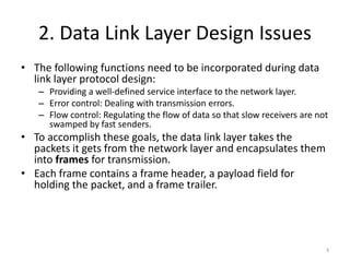
  • 3. 2. Data Link Layer Design Issues • The following functions need to be incorporated during data link layer protocol design: – Providing a well-defined service interface to the network layer. – Error control: Dealing with transmission errors. – Flow control: Regulating the flow of data so that slow receivers are not swamped by fast senders. • To accomplish these goals, the data link layer takes the packets it gets from the network layer and encapsulates them into frames for transmission. • Each frame contains a frame header, a payload field for holding the packet, and a frame trailer. 3
  • 4. 2. Data Link Layer Design Issues 4
  • 5. 2.1Services Provided to the Network Layer • The data link layer transfers data from the network layer on the source machine to the network layer on the destination machine. 5
  • 6. 2.1 Services Provided to the Network Layer • The data link layer can be designed to offer different services. • The actual services that are offered vary from protocol to protocol. • Three possibilities of services are: – Unacknowledged connectionless service. – Acknowledged connectionless service. – Acknowledged connection-oriented service. 6
  • 7. 2.1 Services Provided to the Network Layer • Unacknowledged connectionless service. – Unacknowledged connectionless service consists of having the source machine send independent frames to the destination machine without having the destination machine acknowledge them. – Ethernet is a good example of a data link layer that provides this class of service. – No logical connection is established beforehand or released afterward. – If a frame is lost due to noise on the line, no attempt is made to detect the loss or recover from it in the data link layer. – This class of service is appropriate when the error rate is very low, so recovery is left to higher layers. – It is also appropriate for real-time traffic, such as voice, in which late data are worse than bad data. 7
  • 8. 2.1 Services Provided to the Network Layer • Acknowledged connectionless service. – When this service is offered, there are still no logical connections used, but each frame sent is individually acknowledged. – In this way, the sender knows whether a frame has arrived correctly or been lost. – If it has not arrived within a specified time interval, it can be sent again. – This service is useful over unreliable channels, such as wireless systems. 802.11 (WiFi) is a good example of this class of service. 8
  • 9. 2.1 Services Provided to the Network Layer • Acknowledged connection-oriented service. – With this service, the source and destination machines establish a connection before any data are transferred. – Each frame sent over the connection is numbered, and the data link layer guarantees that each frame sent is indeed received. – Guarantees that all frames are received in the right order. – It is appropriate over long, unreliable links such as a satellite channel or a long-distance telephone circuit. 9
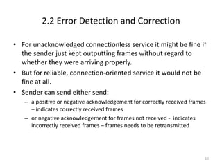
  • 10. 2.2 Error Detection and Correction • For unacknowledged connectionless service it might be fine if the sender just kept outputting frames without regard to whether they were arriving properly. • But for reliable, connection-oriented service it would not be fine at all. • Sender can send either send: – a positive or negative acknowledgement for correctly received frames – indicates correctly received frames – or negative acknowledgement for frames not received - indicates incorrectly received frames – frames needs to be retransmitted 10
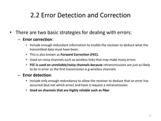
  • 11. 2.2 Error Detection and Correction • There are two basic strategies for dealing with errors: – Error correction: • Include enough redundant information to enable the receiver to deduce what the transmitted data must have been. • This is also known as Forward Correction (FEC). • Used on noisy channels such as wireless links that may make many errors • FEC is used on unreliable/noisy channels because retransmissions are just as likely to be in error as the first transmission e.g wireless channels – Error detection: • Include only enough redundancy to allow the receiver to deduce that an error has occurred (but not which error) and have it request a retransmission. • Used on channels that are highly reliable such as fiber 11
  • 12. 3.Elementary Data Link Protocols • Data Link Layer protocols are responsible to ensure and confirm that the bits and bytes that are received are identical to the bits and bytes being transferred from the sender. • Data Link Layer protocols refers a set of specifications that are used for implementation of data link layer • Elementary data link protocols refer to basic data link protocols. • We look at the basic data link protocols before we look at more advanced ones. • We will look at simplex protocols here 12
  • 13. 3.Elementary Data Link Protocols • Some of the data link layer process and the physical layer process run on dedicated hardware called a NIC (Network Interface Card). • The rest of the link layer process and the network layer process run on the main CPU as part of the operating system, with the software for the link layer process often taking the form of a device driver. 13
  • 14. 3. Elementary Data Link Protocols Continued  Some definitions needed in the protocols to follow. These are located in the file protocol.h. 14
  • 15. (1.2)Protocol Definitions (ctd.) Some definitions needed in the protocols to follow. These are located in the file protocol.h. 15
  • 16. 3. Elementary Data Link Protocols • A frame is composed of four fields: kind, seq, ack, and info • The first three of which contain control information and the last of which may contain actual data to be transferred. These control fields are collectively called the frame header. • The kind field tells whether there are any data in the frame, because some of the protocols distinguish frames containing only control information from those containing data as well. • The seq and ack fields are used for sequence numbers and acknowledgements, respectively; their use will be described in more detail later. • The info field of a data frame contains a single packet; the info field of a control frame is not used. 16
  • 17. 3. Elementary Data Link Protocols • Initially, the receiver has nothing to do. It just sits around waiting for something to happen. • In the example protocols we will indicate that the data link layer is waiting for something to happen by the procedure call wait for event(&event). • This procedure only returns when something has happened (e.g., a frame has arrived). • Upon return, the variable event tells what happened. • The set of possible events differs for the various protocols depending on the complexity of the protocol 17
  • 18. 3. Elementary Data Link Protocols • When a frame arrives at the receiver, the checksum is recomputed. • If the checksum in the frame is incorrect (i.e., there was a transmission error), the data link layer is so informed (event = cksum err). • If the inbound frame arrived undamaged, the data link layer is also informed (event = frame arrival) so that it can acquire the frame for inspection using from physical layer. • As soon as the receiving data link layer has acquired an undamaged frame, it checks the control information in the header, and, if everything is all right, passes the packet portion to the network layer. 18
  • 19. 3. Elementary Data Link Protocols • The procedures to network layer and from network layer are used by the data link layer to pass packets to the network layer and accept packets from the network layer, respectively. • Note that from physical layer and to physical layer pass frames between the data link layer and the physical layer. • In other words, to network layer and from network layer deal with the interface between layers 2 and 3, whereas from physical layer and to physical layer deal with the interface between layers 1 and 2. 19
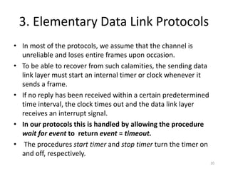
  • 20. 3. Elementary Data Link Protocols • In most of the protocols, we assume that the channel is unreliable and loses entire frames upon occasion. • To be able to recover from such calamities, the sending data link layer must start an internal timer or clock whenever it sends a frame. • If no reply has been received within a certain predetermined time interval, the clock times out and the data link layer receives an interrupt signal. • In our protocols this is handled by allowing the procedure wait for event to return event = timeout. • The procedures start timer and stop timer turn the timer on and off, respectively. 20
  • 21. 3. Elementary Data Link Protocols • Timeout events are possible only when the timer is running and before stop timer is called. • It is explicitly permitted to call start timer while the timer is running; such a call simply resets the clock to cause the next timeout after a full timer interval has elapsed (unless it is reset or turned off). 21
  • 22. 3. Elementary Data Link Protocols • The procedures enable network layer and disable network layer are used in the more sophisticated protocols. • When the data link layer enables the network layer, the network layer is then permitted to interrupt when it has a packet to be sent. • We indicate this with event = network layer ready. • When the network layer is disabled, it may not cause such events. • By being careful about when it enables and disables its network layer, the data link layer can prevent the network layer from swamping it with packets for which it has no buffer space. 22
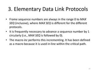
  • 23. 3. Elementary Data Link Protocols • Frame sequence numbers are always in the range 0 to MAX SEQ (inclusive), where MAX SEQ is different for the different protocols. • It is frequently necessary to advance a sequence number by 1 circularly (i.e., MAX SEQ is followed by 0). • The macro inc performs this incrementing. It has been defined as a macro because it is used in-line within the critical path. 23
  • 24. 3. Elementary Data Link Protocols • There are three types of elementary data link protocols: – An Unrestricted Simplex Protocol – A Simplex Stop-and-Wait Protocol – A Simplex Protocol for a Noisy Channel • They are all simplex protocols - data is transmitted in one direction only 24
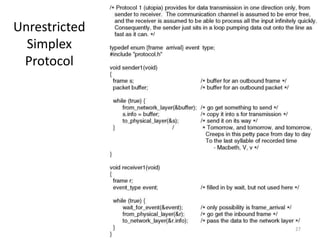
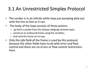
  • 25. 3.1 An Unrestricted Simplex Protocol • This protocol assumes nothing ever goes wrong • Data are transmitted in one direction only. • Both the transmitting and receiving network layers are always ready. • Infinite buffer space is available. • And best of all, the communication channel between the data link layers never damages or loses frames. • No sequence numbers or acknowledgements are used here, so MAX SEQ is not needed. • The only event type possible is frame arrival (i.e., the arrival of an undamaged frame). 25
  • 26. 3.1 An Unrestricted Simplex Protocol • The protocol consists of two distinct procedures, a sender and a receiver. • The sender runs in the data link layer of the source machine, and the receiver runs in the data link layer of the destination machine. 26
  • 28. 3.1 An Unrestricted Simplex Protocol • The sender is in an infinite while loop just pumping data out onto the line as fast as it can. • The body of the loop consists of three actions: – go fetch a packet from the (always obliging) network layer, – construct an outbound frame using the variables, – and send the frame on its way. • Only the info field of the frame is used by this protocol, because the other fields have to do with error and flow control and there are no errors or flow control restrictions here. 28
  • 29. 3.1 An Unrestricted Simplex Protocol • The receiver is equally simple. • Initially, it waits for something to happen, the only possibility being the arrival of an undamaged frame. • Eventually, the frame arrives and the procedure wait for event returns, with event set to frame arrival (which is ignored anyway). • The call to from physical layer removes the newly arrived frame from the hardware buffer and puts it in the variable r, where the receiver code can get at it. • Finally, the data portion is passed on to the network layer, and the data link layer settles back to wait for the next frame, effectively suspending itself until the frame arrives. 29
  • 30. 3.2 A Simplex Stop-and-Wait Protocol • Now we will tackle the problem of preventing the sender from flooding the receiver with frames faster than the latter is able to process them because of limited buffer space -> Flow control. • Solution to this problem is to have the receiver provide feedback to the sender. • After having passed a packet to its network layer, the receiver sends a little dummy frame back to the sender which, in effect, gives the sender permission to transmit the next frame. 30
  • 31. 3.2 A Simplex Stop-and-Wait Protocol • After having sent a frame, the sender is required by the protocol to bide its time until the little dummy (i.e., acknowledgement) frame arrives. • This delay is a simple example of a flow control protocol. • Protocols in which the sender sends one frame and then waits for an acknowledgement before proceeding are called stop-and-wait. 31
  • 33. 3.2 A Simplex Stop-and-Wait Protocol • As in protocol 1, the sender starts out by fetching a packet from the network layer, using it to construct a frame, and sending it on its way. • But now, unlike in protocol 1, the sender must wait until an acknowledgement frame arrives before looping back and fetching the next packet from the network layer. • The sending data link layer need not even inspect the incoming frame as there is only one possibility. • The incoming frame is always an acknowledgement. 33
  • 34. 3.2 A Simplex Stop-and-Wait Protocol • The only difference between receiver1 and receiver2 is that after delivering a packet to the network layer, receiver2 sends an acknowledgement frame back to the sender before entering the wait loop again. 34
  • 35. 3.3 A Simplex Protocol for a Noisy Channel • Now let us consider the normal situation of a communication channel that makes errors. • Frames may be either damaged or lost completely. • However, we assume that if a frame is damaged in transit, the receiver hardware will detect this • Protocols in which the sender waits for a positive acknowledgement before advancing to the next data item are often called ARQ (Automatic Repeat reQuest) or PAR (Positive Acknowledgement with Retransmission). 35
  • 36. A Simplex Protocol for a Noisy Channel A positive acknowledgement with retransmission protocol. Continued  36
  • 37. A Simplex Protocol for a Noisy Channel A positive acknowledgement with retransmission protocol. 37
  • 38. 3.3 A Simplex Protocol for a Noisy Channel • Protocol 3 differs from its predecessors in that both sender and receiver have a variable whose value is remembered while the data link layer is in the wait state. • The sender remembers the sequence number of the next frame to send in next frame to send; the receiver remembers the sequence number of the next frame expected in frame expected. • After transmitting a frame, the sender starts the timer running. 38
  • 39. 3.3 A Simplex Protocol for a Noisy Channel • If it was already running, it will be reset to allow another full timer interval. • Only when that interval has elapsed is it safe to assume that either the transmitted frame or its acknowledgement has been lost, and to send a duplicate frame. • After transmitting a frame and starting the timer, the sender waits for something exciting to happen. • Only three possibilities exist: – an acknowledgement frame arrives undamaged, – a damaged acknowledgement frame staggers in, – or the timer expires. 39
  • 40. 3.3 A Simplex Protocol for a Noisy Channel • If a valid acknowledgement comes in, the sender fetches the next packet from its network layer and puts it in the buffer, overwriting the previous packet. • It also advances the sequence number. • If a damaged frame arrives or the timer expires, neither the buffer nor the sequence number is changed so that a duplicate can be sent. • In all cases, the contents of the buffer (either the next packet or a duplicate) are then sent. 40
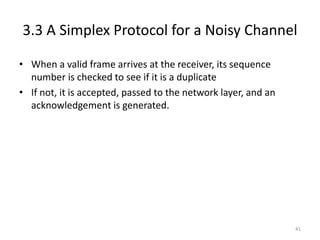
  • 41. 3.3 A Simplex Protocol for a Noisy Channel • When a valid frame arrives at the receiver, its sequence number is checked to see if it is a duplicate • If not, it is accepted, passed to the network layer, and an acknowledgement is generated. 41
  • 42. Sliding Window Protocols • In the previous protocols, data frames were transmitted in one direction only. • In most practical situations, there is a need to transmit data in both directions. • One way of achieving full-duplex data transmission is to run two instances of one of the previous protocols, each using a separate link for simplex data traffic (in different directions). • Each link is then comprised of a ‘‘forward’’ channel (for data) and a ‘‘reverse’’ channel (for acknowledgements). • In both cases the capacity of the reverse channel is almost entirely wasted – you only use it to send ack frames 42
  • 43. 4. Sliding Window Protocols • A better idea is to use the same link for data in both directions. • Sliding window protocols allow sending of data in both directions • After all, in protocols 2 and 3 it was already being used to transmit frames both ways, and the reverse channel normally has the same capacity as the forward channel. • In this model the data frames from A to B are intermixed with the acknowledgement frames from A to B - piggybaking. • By looking at the kind field in the header of an incoming frame, the receiver can tell whether the frame is data or an acknowledgement. 43
  • 44. • A sliding window of size 1, with a 3-bit sequence number. (a) Initially. (b) After the first frame has been sent. (c) After the first frame has been received. (d) After the first acknowledgement has been received. 4. Sliding Window Protocols 44
  • 45. 4. Sliding Window Protocols • We will look at three slisding window protocols: – One bit sliding window protocol – Stop and wait protocol – Selective repeat protocol • The are all bidirectional protocols • In these, as in all sliding window protocols, each outbound frame contains a sequence number, ranging from 0 up to some maximum. • The stop-and-wait sliding window protocol uses n = 1, restricting the sequence numbers to 0 and 1, but more sophisticated versions can use an arbitrary n. 45
  • 46. 4. Sliding Window Protocols • The essence of all sliding window protocols is that at any instant of time, the sender maintains a set of sequence numbers corresponding to frames it is permitted to send. • These frames are said to fall within the sending window. • Similarly, the receiver also maintains a receiving window corresponding to the set of frames it is permitted to accept. • The sequence numbers within the sender’s window represent frames that have been sent or can be sent but are as yet not acknowledged. 46
  • 47. 4. Sliding Window Protocols • Since frames currently within the sender’s window may ultimately be lost or damaged in transit, the sender must keep all of these frames in its memory for possible retransmission. • Thus, if the maximum window size is n, the sender needs n buffers to hold the unacknowledged frames. • If the window ever grows to its maximum size, the sending data link layer must forcibly shut off the network layer until another buffer becomes free. • The receiving data link layer’s window corresponds to the frames it may accept. • Any frame falling within the window is put in the receiver’s buffer. 47
  • 48. 4.1 One Bit Sliding Window • Before tackling the general case, let us examine a sliding window protocol with a window size of 1. • Such a protocol uses stop-and-wait since the sender transmits a frame and waits for its acknowledgement before sending the next one. • Under normal circumstances, one of the two data link layers goes first and transmits the first frame. 48
  • 49. 4.1 One Bit Sliding Window • The starting machine fetches the first packet from its network layer, builds a frame from it, and sends it. • When this (or any) frame arrives, the receiving data link layer checks to see if it is a duplicate, just as in protocol 3. • If the frame is the one expected, it is passed to the network layer and the receiver’s window is slid up. • The acknowledgement field contains the number of the last frame received without error. 49
  • 50. 4.1 One Bit Sliding Window • If this number agrees with the sequence number of the frame the sender is trying to send, the sender knows it is done with the frame stored in buffer and can fetch the next packet from its network layer. • If the sequence number disagrees, it must continue trying to send the same frame. • Whenever a frame is received, a frame is also sent back. 50
  • 51. 4.1 A One-Bit Sliding Window Protocol • The notation is (seq, ack, packet number). 51
  • 52. 4.1 A One-Bit Sliding Window Protocol Continued  52
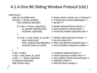
  • 53. 4.1 A One-Bit Sliding Window Protocol (ctd.) 53
  • 54. 4.2 A Protocol Using Go-Back-N • Until now we have made the tacit assumption that the transmission time required for a frame to arrive at the receiver plus the transmission time for the acknowledgement to come back is negligible. • Sometimes this assumption is clearly false. • In these situations the long round-trip time can have important implications for the efficiency of the bandwidth utilization. • As an example, consider a 50-kbps satellite channel with a 500-msec round-trip propagation delay. • Let us imagine trying to use protocol 4 to send 1000-bit frames via the satellite. At t = 0 the sender starts sending the first frame. 54
  • 55. 4.2 A Protocol Using Go-Back-N • At t = 20 msec the frame has been completely sent. • Not until t = 270 msec has the frame fully arrived at the receiver, and not until t = 520 msec has the acknowledgement arrived back at the sender, under the best of circumstances (of no waiting in the receiver and a short acknowledgement frame). • This means that the sender was blocked 500/520 or 96% of the time. • In other words, only 4% of the available bandwidth was used. • Clearly, the combination of a long transit time, high bandwidth, and short frame length is disastrous in terms of efficiency. 55
  • 56. 4.2 A Protocol Using Go-Back-N • The problem described here can be viewed as a consequence of the rule requiring a sender to wait for an acknowledgement before sending another frame. • If we relax that restriction, much better efficiency can be achieved. • Basically, the solution lies in allowing the sender to transmit up to w frames before blocking, instead of just 1. • With a large enough choice of w the sender will be able to continuously transmit frames since the acknowledgements will arrive for previous frames before the window becomes full, preventing the sender from blocking. 56
  • 57. 4.2 A Protocol Using Go Back N 57
  • 58. 4.2 A Protocol Using Go Back N 58
  • 59. 4.2 A Protocol Using Go-Back-N • This technique of keeping multiple frames in flight is an example of pipelining. Pipelining frames over an unreliable communication channel raises some serious issues. • First, what happens if a frame in the middle of a long stream is damaged or lost? • Large numbers of succeeding frames will arrive at the receiver before the sender even finds out that anything is wrong. • When a damaged frame arrives at the receiver, it obviously should be discarded, but what should the receiver do with all the correct frames following it? • Remember that the receiving data link layer is obligated to hand packets to the network layer in sequence. 59
  • 60. 4.2 A Protocol Using Go-Back-N • One option, called go-back-n, is for the receiver simply to discard all subsequent frames, sending no acknowledgements for the discarded frames. • This strategy corresponds to a receive window of size 1. • In other words, the data link layer refuses to accept any frame except the next one it must give to the network layer. • Eventually, the sender will time out and retransmit all unacknowledged frames in order, starting with the damaged or lost one. • This approach can waste a lot of bandwidth if the error rate is high. 60
  • 61. 4.3 A Protocol Using Selective Repeat • The go-back-n protocol works well if errors are rare, but if the line is poor it wastes a lot of bandwidth on retransmitted frames. • An alternative strategy, the selective repeat protocol, is to allow the receiver to accept and buffer the frames following a damaged or lost one. • In this protocol, both sender and receiver maintain a window of outstanding and acceptable sequence numbers, respectively. • The sender’s window size starts out at 0 and grows to some predefined maximum. 61
  • 62. 4.3 A Protocol Using Selective Repeat • When it is used, a bad frame that is received is discarded, but any good frames received after it are accepted and buffered. • When the sender times out, only the oldest unacknowledged frame is retransmitted. • If that frame arrives correctly, the receiver can deliver to the network layer, in sequence, all the frames it has buffered. • Selective repeat corresponds to a receiver window larger than 1. 62
  • 63. 4.3 Sliding Window Protocol Using Selective Repeat 63