SlideShare a Scribd company logo
Turbojet Turbofan
Turboprop
COMPRESSOR AND ITS TYPES
COMPRESSOR
Definition
 It is that part of a jet engine which
compresses the ingested air and then, feeds
it to combustion chamber.
 Power absorbing device.
Q. How a compressor works?
 Compressor is continuous flow machine which
function by imparting kinetic energy to the air by means
of a rotary part (rotor blades or impeller), subsequently
diffusing the velocity into static pressure rise.
WORKING OF A COMPRESSOR
ROLE OF A COMPRESSOR
 Compressor in a gas turbine engine is to
provide a maximum of high-pressure air.
Q. What is the use of high-pressure air?
 This air is then heated in a combustion
chamber and expanded in a turbine.
 Energy released in the combustion chamber is
proportional to the mass of the air consumed.
 Its efficient operation (maximum compression with
minimum temperature rise) is the key to high overall
engine performance.
ROLE OF A COMPRESSOR
Q. What is the importance of compressor efficiency?
 The compressor efficiency will determine the power
necessary to create the pressure rise and will affect the
temperature change in the combustion chamber.
 Present day compressors have compression ratios
over 25:1.
 Compression ratio.
 Compressors have efficiencies over 90 percent.
 Mass flow rate of air up to approximately 350 lbs/s
(158.8 kg/s).
ROLE OF A COMPRESSOR
With the addition of a fan,
total pressure ratios of more
than 25:1 and mass airflows
of 1000 lbs/s (453.6 kg/s)
have been achieved.
AMENDMENTS IN A JET ENGINE
T-S DIAGRAM
TYPES OF A COMPRESSOR
Q. What are different types of a compressor?
 There are two types of compressors with respect to
airflow:-
Centrifugal compressor
Axial flow compressor
CENTRIFUGAL COMPRESSOR
The airflow is radial, i.e. the
flow of air is outward from the
centre of the compressor.
CENTRIFUGAL COMPRESSOR
It is used extensively in the early days of gas turbines.
These are limited to the small gas turbine ‘gas
generators’ for engine air starters and missile engines.
Single Entry Impeller Double Entry Impeller
Turbojet Engine-Centrifugal Compressor
AXIAL FLOW COMPRESSOR
 Compressor in
which air flows axially
i.e. the flow of air is
maintained parallel to
the compressor’s
shaft.
 Used in turbofan
and turbojet engines.
AXIAL FLOW COMPRESSOR
COMPARISON OF COMPRESSORS
Centrifugal
compressors
generally need to
operate at much
higher rpm than
axial compressors.
Axial Flow Compressor
COMBINATION OF BOTH
COMPRESSORS
Axial/centrifugal
compressor
combinations are
used extensively
in turbo-shaft
and turboprop
engines.
FACTORS AFFECTING THE PERFORMANCE
Q. What are those factors which affect the performance
of a compressor?
The principal factors are:-
Aerofoil sections,
Pitch angles and
The length/chord ratios of the blades
Clearance between the blade tips and the
compressor annulus
REQUIREMENTS OF A COMPRESSOR
Introduction
 SFC is very important in case of internal
combustion engines.
 The efficiency of a compressor is one of the
factors directly influencing the specific fuel
consumption (SFC).
FACTORS AFFECTING THE PERFORMANCE
Q. What are those factors which affect the performance
of a compressor?
The principal factors are:-
Aerofoil sections,
Pitch angles and
The length/chord ratios of the blades
Clearance between the blade tips and the
compressor annulus
HIGH PRESSURE RATIO
It is the ratio of pressure of the air at the outlet of
compressor to the inlet.
The thermal efficiency and the work output are both
proportional to the compressor pressure ratio.
The centrifugal compressor has a maximum pressure
ratio of about 4.5:1 for a single stage.
Raised to approximately 6:1 by using a two stage,
single-entry centrifugal compressor.
HIGH PRESSURE RATIO
 For axial compressors, it is a matter of stability and complexity.
 The current values are 10:1 for single-spool compressors.
 For multi-spool compressors, the pressure ratio is in excess of
25:1.
 Higher pressure ratios give higher engine efficiency due to an
improved SFC.
Compressor pressure ratio
SFC and Pressure Ratio
Axial Flow Compressor
High Mass Flow
 Jet engine air mass flows are becoming much larger.
 Ram-compression
 Must be matched with the swallowing capacity of the
compressor.
 For transport aircraft, the required air mass flow at altitude
requires large diameter compressors.
 Larger diameter fans for dual flow engines are required (high by-
pass turbofan engines).
Stable Operation Under all Conditions
 Both centrifugal and axial compressors are liable to exhibit
unstable characteristics under certain operating conditions.
 The centrifugal type is less likely to stall and surge than the axial.
 But it is not capable of the high pressure ratios now required.
 In high pressure ratio axial compressors anti-stall/surge devices
are often a design requirement to guard against unstable
conditions.
COMPRESSOR DESIGN
 Compressor design in most engines is a compromise between
high performance over a narrow band of rpm, and moderate
performance over a wide band of rpm.
 Consequently, although it is possible for the compressor to be
designed so that very high efficiency is obtained at the highest
power.
 Any deviation from the designed conditions may cause significant
changes in the aerodynamic flow leading to a loss of efficiency
and unstable conditions within the engine.
Axial Flow Compressor-Single Spool
Axial Flow Compressor-Double Spool
Q. What is a compressor?
Q. What are different types of
compressors?
Q. Which compressor is used in T-37
Aircraft’s engine?
CENTRIFUGAL COMPRESSOR
Definition
 1. The airflow is radial, i.e. the flow of air is
outward from the centre of the compressor.
Explanation
 2. (a) Centrifugal force
 (b) Limited to the small gas turbine (gas
generators) for engine air starters and
missile engines.
Purpose
3. To increase the mass flow rate through the
engine which results in generation of thrust.
Principle of Operation
4. To impart kinetic energy to the airflow and
then converts this kinetic energy into pressure
energy.
Main Components
5. (a) Compressor casing
(b) Impeller
(c) Diffuser
Centrifugal Compressor
Compressor Casing
6. (a) Embodies the air inlet guide vanes
(IGVS) and outlet ports.
(b) Air entering the intake at atmospheric
temperature and pressure passes through the
fixed intake guide vanes.
(c) IGVS direct the air smoothly into the centre
of the impeller.
(d) Outlet ports direct the air into the
combustion chamber.
Impeller
7. (a) Rotating part
(b) Rotated at high speed by the turbine
(c) The incoming air smoothly fall at the centre
of the impeller.
(d) Designed to admit the air without excessive
velocity
(e) The air is picked up by the rotating guide
vanes of the impeller, and centrifugal force causes
the air to flow outwards along the vanes to the
impeller tip.
Impeller
(e) Air leaves the impeller tip approximately at
right angles to its intake direction.
(f) Impellers operate at tip speeds of up to 500
meter per second to give high tangential air
velocity for conversion to pressure.
(g) Impellers are of two types
(i) Single entry impeller
(ii) Double entry impeller
Centrifugal Compressor
Single Entry Impeller
8. Type of an impeller in which air is
falling on one side (towards intake).
(a) Single Stage
(b) Double Stage
Advantages
9. (a) The single-sided, single- entry
impeller lends itself to efficient ducting.
(b) Makes more use of the ram
effect at high speeds than does
the double-entry arrangement.
(c) This leads
to an increase in
the overall
diameter of the
engine for a
given thrust.
Double Entry Impeller
10. (a) Type of an impeller in
which air is falling on
both sides of impeller.
(b) It can handle a higher
mass flow.
(c) The airflow to the rear
side is reversed in
direction.
(d) Penalties are
(i) Relatively
inefficient intake
ducting.
(ii) Preheating
imparted to the air
by virtue of its
reversal on entry.
Airflow through impellers
Diffuser
11. (a) Used to convert
energy of the air
leaving the compressor to
pressure energy.
(b) Formed integral with
the compressor
casing or be bolted to it.
(c) The vane passages
are divergent to
convert the velocity energy
into pressure energy.
AXIAL FLOW COMPRESSOR
Definition
1. Compressor in which air flows axially
Purpose
2. Converts kinetic energy into static pressure
energy
- How it converts?
• Rows of rotating blades (rotors) impart kinetic energy
to the air
• Alternate rows of stationary diffusing vanes (stators),
convert the kinetic energy to pressure energy
Construction
3. Consists of an annular passage
Series of small blades of aerofoil section, alternately
rotating on a central shaft assembly or fixed to the outer
case
Each pair of rotor and stator rings is termed a stage
Typical gas turbine engine may have
between 10 and 15 stages on a single
spool
Divided between multiple spools
An additional row of stator blades may
be fitted to single spool-engines
Automatically adjusted to suit prevailing intake
conditions
Outlet guide vanes straighten the airflow into the
combustion stage
The cross-sectional area of the annulus is
progressively reduced
To maintain constant axial velocity with increasing
density
Types
4. (a) Single spool
(b) Multi spool
DOUBLE SPOOL
MULTI SPOOL COMPRESSOR
Axial-flow Compressor
Axial-Centrifugal-Flow Compressor
COMPRESSOR STALL AND SURGE
Introduction
 A compressor is designed to operate between certain
critical limits of rpm, pressure ratio and mass flow.
 If operation is attempted outside these limits, the flow
around the compressor blades breaks down to give
violent turbulent flow.
 When this occurs, the compressor will stall or surge.
 The greater the number of stages in the compressor
more complex will be the situation.
Stalling of Compressor Rotor Blades
 These blades (which are like small
aero foils) stall in the same way as the
wings of an aircraft.
 Stalling of wing occurs at high angle of
attack when the flow separates from
the upper surface of wing.
 Since the pitch of the blades is fixed,
this condition is brought about by a
change in direction of the relative
airflow (V1).
Stalling of Compressor Rotor Blades
 A reduction in the axial
velocity Va to a value Va1
while the rpm and hence
blade speed U remains
constant.
 Increases the angle of
attack.
 If the fall in Va is
sufficient, the blade
stalling angle will be
reached.
Stalling of Compressor Rotor Blades
 The fall in Va at constant rpm is associated with a
reduction in mass flow from the stable value due to a
variety of causes.
 Generally, when the critical condition is approached due
to velocity gradients and local effects, a group of blades
will be affected first rather than the complete blade row.
 A stall cell would be generated.
 The stall “cell” moves around the blade row.
 There may be several “cells” which can stall the whole
row.
 Compressor Stall at Low Rpm
 Compressor Acceleration Stall
 Compressor Stall at High Rpm
TYPES OF COMPRESSOR STALL
Compressor Stall at Low Rpm
 With a reduction in mass flow rate at low rpm, the angle of
attack of the first low pressure stage is greater than that of
the high pressure stages.
 Due to this reason the low pressure stages will first stall.
 It is not necessary that the succeeding stages will be
affected.
 Stalling of the initial compressor stages may be indicated by
an audible rumbling (low or dull) noise and a rise in turbine
gas temperature (TGT).
 In the latter case, a further reduction in mass flow would
cause a successive breakdown of the remaining stages.
Compressor Acceleration Stall
 On starting or during rapid acceleration from low rpm,
there will be increase in mass flow rate of air and
additional fuel will be sprayed in the combustion
chamber.
 During combustion, there will be sudden increase in
combustion pressure which causes a momentary back
pressure.
 This affects the compressor performance and hence,
there will be reduction in the mass flow rate which causes
the same effects as described above.
Compressor Stall at High RPM
 At high compressor rpm, the angle of attack of all the
stages is almost same.
 If there is sudden reduction in mass flow then a
simultaneous breakdown of flow through all the stages is
caused.
 This type of stall is usually initiated by airflow interference
at the intake during certain maneuvers or gun firing.
 The compressor may be un-stalled by throttling fully back,
but in some cases it may be necessary to stop the engine.
COMPRESSOR SURGE
 In an axial compressor, surging indicates a complete
instability of flow through the compressor.
 Surging is a motion of airflow forwards and backwards
through the compressor, which is accompanied by audible
indications ranging from soft rumblings to an abrupt
explosion and vibration, depending on the degree of
severity.
 Surge is indicated by rapid rise in turbine gas temperature
(TGT ) and fluctuation or falling of rpm.
 Compressor surge causes very severe vibrations and
excessive temperatures in the engine.
 A compressor stall usually leads to a compressor surge.

More Related Content

PPTX
Aircraft cabin pressurization system
PPTX
Air cargo overview ppt
PPTX
Jet Engines
PPT
PPTX
Cubesat satellite
PPTX
Axial Flow Compressor.
PDF
EASA Part-66 Module15 mcq's
Aircraft cabin pressurization system
Air cargo overview ppt
Jet Engines
Cubesat satellite
Axial Flow Compressor.
EASA Part-66 Module15 mcq's

What's hot (20)

PDF
Subsonic and supersonic air intakes
PPTX
Piston engine powerplant
PPTX
Aircraft Gas Turbine Engines
PDF
Aircraft Engine part1
PPTX
i c engines efficiencies
PDF
Gas turbine engine
PDF
Aircraft control systems
PPTX
Scramjet engine
PPTX
Introduction to turbojet engines
PPTX
Turbocharging
PPTX
Aircraft landing gear
PPTX
Gas turbine engine
PDF
Gas Turbine and Jet propulsion
PDF
Automobile - AC SYSTEM
PPTX
Fundamentals of jet propulsion ppt
PPTX
Aircraft fuel system
PPTX
Performance testing of IC engine
DOCX
V n diagram
PPTX
Gas turbines
PDF
Proulsion I - SOLVED QUESTION BANK - RAMJET ENGINE
Subsonic and supersonic air intakes
Piston engine powerplant
Aircraft Gas Turbine Engines
Aircraft Engine part1
i c engines efficiencies
Gas turbine engine
Aircraft control systems
Scramjet engine
Introduction to turbojet engines
Turbocharging
Aircraft landing gear
Gas turbine engine
Gas Turbine and Jet propulsion
Automobile - AC SYSTEM
Fundamentals of jet propulsion ppt
Aircraft fuel system
Performance testing of IC engine
V n diagram
Gas turbines
Proulsion I - SOLVED QUESTION BANK - RAMJET ENGINE
Ad

Similar to Lecture-1- Compressor and its Types.ppt (20)

PPTX
Comparison Centrifugal and axial compessor
PDF
Chapter 3.3 compressed air system
PDF
Centrifugal compressor: Casing and inlet. Impellers
PPT
Air Compressor
PPTX
Compressor and Types
PDF
Compressor Classifications.pdf
PDF
AIR COMPRESSOR Energy Efficiency calc.pdf
PDF
Compressor
PDF
Compressed air_system ( chapter complete )
PPTX
1. Principle of operation of centrifugal and axial compressors.pptx
PPTX
Centrifugal Compressor
PPTX
aircompressors- mechanicakl211109061833.pptx
PPTX
Variable cycle engine ppt.
PPTX
Air Compressor reciprocating single stage
PDF
Axial flow compressors
PPTX
Industrial compressor
DOCX
TYPES OF COMPRESSORS
PPTX
INTRODUTION OF AIRCRAFT PROPULSION-new.pptx
PDF
Introduction of aircraft propulsion.pdf
PPTX
Air compresser by Ravi Gelani
Comparison Centrifugal and axial compessor
Chapter 3.3 compressed air system
Centrifugal compressor: Casing and inlet. Impellers
Air Compressor
Compressor and Types
Compressor Classifications.pdf
AIR COMPRESSOR Energy Efficiency calc.pdf
Compressor
Compressed air_system ( chapter complete )
1. Principle of operation of centrifugal and axial compressors.pptx
Centrifugal Compressor
aircompressors- mechanicakl211109061833.pptx
Variable cycle engine ppt.
Air Compressor reciprocating single stage
Axial flow compressors
Industrial compressor
TYPES OF COMPRESSORS
INTRODUTION OF AIRCRAFT PROPULSION-new.pptx
Introduction of aircraft propulsion.pdf
Air compresser by Ravi Gelani
Ad

Recently uploaded (20)

PDF
BIO-INSPIRED ARCHITECTURE FOR PARSIMONIOUS CONVERSATIONAL INTELLIGENCE : THE ...
PDF
86236642-Electric-Loco-Shed.pdf jfkduklg
PPTX
UNIT 4 Total Quality Management .pptx
PDF
PREDICTION OF DIABETES FROM ELECTRONIC HEALTH RECORDS
PDF
UNIT no 1 INTRODUCTION TO DBMS NOTES.pdf
PDF
Mitigating Risks through Effective Management for Enhancing Organizational Pe...
PPT
Occupational Health and Safety Management System
PDF
Integrating Fractal Dimension and Time Series Analysis for Optimized Hyperspe...
PPTX
Fundamentals of Mechanical Engineering.pptx
PDF
EXPLORING LEARNING ENGAGEMENT FACTORS INFLUENCING BEHAVIORAL, COGNITIVE, AND ...
PPTX
Fundamentals of safety and accident prevention -final (1).pptx
PDF
null (2) bgfbg bfgb bfgb fbfg bfbgf b.pdf
PDF
Abrasive, erosive and cavitation wear.pdf
PPT
introduction to datamining and warehousing
PPTX
Artificial Intelligence
PPTX
introduction to high performance computing
PPTX
Current and future trends in Computer Vision.pptx
PDF
Unit I ESSENTIAL OF DIGITAL MARKETING.pdf
PDF
The CXO Playbook 2025 – Future-Ready Strategies for C-Suite Leaders Cerebrai...
PDF
Level 2 – IBM Data and AI Fundamentals (1)_v1.1.PDF
BIO-INSPIRED ARCHITECTURE FOR PARSIMONIOUS CONVERSATIONAL INTELLIGENCE : THE ...
86236642-Electric-Loco-Shed.pdf jfkduklg
UNIT 4 Total Quality Management .pptx
PREDICTION OF DIABETES FROM ELECTRONIC HEALTH RECORDS
UNIT no 1 INTRODUCTION TO DBMS NOTES.pdf
Mitigating Risks through Effective Management for Enhancing Organizational Pe...
Occupational Health and Safety Management System
Integrating Fractal Dimension and Time Series Analysis for Optimized Hyperspe...
Fundamentals of Mechanical Engineering.pptx
EXPLORING LEARNING ENGAGEMENT FACTORS INFLUENCING BEHAVIORAL, COGNITIVE, AND ...
Fundamentals of safety and accident prevention -final (1).pptx
null (2) bgfbg bfgb bfgb fbfg bfbgf b.pdf
Abrasive, erosive and cavitation wear.pdf
introduction to datamining and warehousing
Artificial Intelligence
introduction to high performance computing
Current and future trends in Computer Vision.pptx
Unit I ESSENTIAL OF DIGITAL MARKETING.pdf
The CXO Playbook 2025 – Future-Ready Strategies for C-Suite Leaders Cerebrai...
Level 2 – IBM Data and AI Fundamentals (1)_v1.1.PDF

Lecture-1- Compressor and its Types.ppt

  • 3. COMPRESSOR Definition  It is that part of a jet engine which compresses the ingested air and then, feeds it to combustion chamber.  Power absorbing device.
  • 4. Q. How a compressor works?  Compressor is continuous flow machine which function by imparting kinetic energy to the air by means of a rotary part (rotor blades or impeller), subsequently diffusing the velocity into static pressure rise. WORKING OF A COMPRESSOR
  • 5. ROLE OF A COMPRESSOR  Compressor in a gas turbine engine is to provide a maximum of high-pressure air. Q. What is the use of high-pressure air?  This air is then heated in a combustion chamber and expanded in a turbine.
  • 6.  Energy released in the combustion chamber is proportional to the mass of the air consumed.  Its efficient operation (maximum compression with minimum temperature rise) is the key to high overall engine performance. ROLE OF A COMPRESSOR
  • 7. Q. What is the importance of compressor efficiency?  The compressor efficiency will determine the power necessary to create the pressure rise and will affect the temperature change in the combustion chamber.  Present day compressors have compression ratios over 25:1.  Compression ratio.  Compressors have efficiencies over 90 percent.  Mass flow rate of air up to approximately 350 lbs/s (158.8 kg/s). ROLE OF A COMPRESSOR
  • 8. With the addition of a fan, total pressure ratios of more than 25:1 and mass airflows of 1000 lbs/s (453.6 kg/s) have been achieved. AMENDMENTS IN A JET ENGINE
  • 10. TYPES OF A COMPRESSOR Q. What are different types of a compressor?  There are two types of compressors with respect to airflow:- Centrifugal compressor Axial flow compressor
  • 11. CENTRIFUGAL COMPRESSOR The airflow is radial, i.e. the flow of air is outward from the centre of the compressor.
  • 12. CENTRIFUGAL COMPRESSOR It is used extensively in the early days of gas turbines. These are limited to the small gas turbine ‘gas generators’ for engine air starters and missile engines. Single Entry Impeller Double Entry Impeller
  • 14. AXIAL FLOW COMPRESSOR  Compressor in which air flows axially i.e. the flow of air is maintained parallel to the compressor’s shaft.  Used in turbofan and turbojet engines.
  • 16. COMPARISON OF COMPRESSORS Centrifugal compressors generally need to operate at much higher rpm than axial compressors.
  • 18. COMBINATION OF BOTH COMPRESSORS Axial/centrifugal compressor combinations are used extensively in turbo-shaft and turboprop engines.
  • 19. FACTORS AFFECTING THE PERFORMANCE Q. What are those factors which affect the performance of a compressor? The principal factors are:- Aerofoil sections, Pitch angles and The length/chord ratios of the blades Clearance between the blade tips and the compressor annulus
  • 20. REQUIREMENTS OF A COMPRESSOR Introduction  SFC is very important in case of internal combustion engines.  The efficiency of a compressor is one of the factors directly influencing the specific fuel consumption (SFC).
  • 21. FACTORS AFFECTING THE PERFORMANCE Q. What are those factors which affect the performance of a compressor? The principal factors are:- Aerofoil sections, Pitch angles and The length/chord ratios of the blades Clearance between the blade tips and the compressor annulus
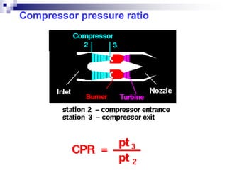
  • 22. HIGH PRESSURE RATIO It is the ratio of pressure of the air at the outlet of compressor to the inlet. The thermal efficiency and the work output are both proportional to the compressor pressure ratio. The centrifugal compressor has a maximum pressure ratio of about 4.5:1 for a single stage. Raised to approximately 6:1 by using a two stage, single-entry centrifugal compressor.
  • 23. HIGH PRESSURE RATIO  For axial compressors, it is a matter of stability and complexity.  The current values are 10:1 for single-spool compressors.  For multi-spool compressors, the pressure ratio is in excess of 25:1.  Higher pressure ratios give higher engine efficiency due to an improved SFC.
  • 27. High Mass Flow  Jet engine air mass flows are becoming much larger.  Ram-compression  Must be matched with the swallowing capacity of the compressor.  For transport aircraft, the required air mass flow at altitude requires large diameter compressors.  Larger diameter fans for dual flow engines are required (high by- pass turbofan engines).
  • 28. Stable Operation Under all Conditions  Both centrifugal and axial compressors are liable to exhibit unstable characteristics under certain operating conditions.  The centrifugal type is less likely to stall and surge than the axial.  But it is not capable of the high pressure ratios now required.  In high pressure ratio axial compressors anti-stall/surge devices are often a design requirement to guard against unstable conditions.
  • 29. COMPRESSOR DESIGN  Compressor design in most engines is a compromise between high performance over a narrow band of rpm, and moderate performance over a wide band of rpm.  Consequently, although it is possible for the compressor to be designed so that very high efficiency is obtained at the highest power.  Any deviation from the designed conditions may cause significant changes in the aerodynamic flow leading to a loss of efficiency and unstable conditions within the engine.
  • 32. Q. What is a compressor? Q. What are different types of compressors? Q. Which compressor is used in T-37 Aircraft’s engine?
  • 33. CENTRIFUGAL COMPRESSOR Definition  1. The airflow is radial, i.e. the flow of air is outward from the centre of the compressor. Explanation  2. (a) Centrifugal force  (b) Limited to the small gas turbine (gas generators) for engine air starters and missile engines.
  • 34. Purpose 3. To increase the mass flow rate through the engine which results in generation of thrust. Principle of Operation 4. To impart kinetic energy to the airflow and then converts this kinetic energy into pressure energy.
  • 35. Main Components 5. (a) Compressor casing (b) Impeller (c) Diffuser
  • 37. Compressor Casing 6. (a) Embodies the air inlet guide vanes (IGVS) and outlet ports. (b) Air entering the intake at atmospheric temperature and pressure passes through the fixed intake guide vanes. (c) IGVS direct the air smoothly into the centre of the impeller. (d) Outlet ports direct the air into the combustion chamber.
  • 38. Impeller 7. (a) Rotating part (b) Rotated at high speed by the turbine (c) The incoming air smoothly fall at the centre of the impeller. (d) Designed to admit the air without excessive velocity (e) The air is picked up by the rotating guide vanes of the impeller, and centrifugal force causes the air to flow outwards along the vanes to the impeller tip.
  • 39. Impeller (e) Air leaves the impeller tip approximately at right angles to its intake direction. (f) Impellers operate at tip speeds of up to 500 meter per second to give high tangential air velocity for conversion to pressure. (g) Impellers are of two types (i) Single entry impeller (ii) Double entry impeller
  • 41. Single Entry Impeller 8. Type of an impeller in which air is falling on one side (towards intake). (a) Single Stage (b) Double Stage Advantages 9. (a) The single-sided, single- entry impeller lends itself to efficient ducting. (b) Makes more use of the ram effect at high speeds than does the double-entry arrangement.
  • 42. (c) This leads to an increase in the overall diameter of the engine for a given thrust.
  • 43. Double Entry Impeller 10. (a) Type of an impeller in which air is falling on both sides of impeller. (b) It can handle a higher mass flow. (c) The airflow to the rear side is reversed in direction.
  • 44. (d) Penalties are (i) Relatively inefficient intake ducting. (ii) Preheating imparted to the air by virtue of its reversal on entry.
  • 46. Diffuser 11. (a) Used to convert energy of the air leaving the compressor to pressure energy. (b) Formed integral with the compressor casing or be bolted to it. (c) The vane passages are divergent to convert the velocity energy into pressure energy.
  • 47. AXIAL FLOW COMPRESSOR Definition 1. Compressor in which air flows axially Purpose 2. Converts kinetic energy into static pressure energy - How it converts? • Rows of rotating blades (rotors) impart kinetic energy to the air • Alternate rows of stationary diffusing vanes (stators), convert the kinetic energy to pressure energy
  • 48. Construction 3. Consists of an annular passage Series of small blades of aerofoil section, alternately rotating on a central shaft assembly or fixed to the outer case Each pair of rotor and stator rings is termed a stage
  • 49. Typical gas turbine engine may have between 10 and 15 stages on a single spool Divided between multiple spools An additional row of stator blades may be fitted to single spool-engines
  • 50. Automatically adjusted to suit prevailing intake conditions Outlet guide vanes straighten the airflow into the combustion stage The cross-sectional area of the annulus is progressively reduced To maintain constant axial velocity with increasing density
  • 51. Types 4. (a) Single spool (b) Multi spool
  • 56. COMPRESSOR STALL AND SURGE Introduction  A compressor is designed to operate between certain critical limits of rpm, pressure ratio and mass flow.  If operation is attempted outside these limits, the flow around the compressor blades breaks down to give violent turbulent flow.  When this occurs, the compressor will stall or surge.  The greater the number of stages in the compressor more complex will be the situation.
  • 57. Stalling of Compressor Rotor Blades  These blades (which are like small aero foils) stall in the same way as the wings of an aircraft.  Stalling of wing occurs at high angle of attack when the flow separates from the upper surface of wing.  Since the pitch of the blades is fixed, this condition is brought about by a change in direction of the relative airflow (V1).
  • 58. Stalling of Compressor Rotor Blades  A reduction in the axial velocity Va to a value Va1 while the rpm and hence blade speed U remains constant.  Increases the angle of attack.  If the fall in Va is sufficient, the blade stalling angle will be reached.
  • 59. Stalling of Compressor Rotor Blades  The fall in Va at constant rpm is associated with a reduction in mass flow from the stable value due to a variety of causes.  Generally, when the critical condition is approached due to velocity gradients and local effects, a group of blades will be affected first rather than the complete blade row.  A stall cell would be generated.  The stall “cell” moves around the blade row.  There may be several “cells” which can stall the whole row.
  • 60.  Compressor Stall at Low Rpm  Compressor Acceleration Stall  Compressor Stall at High Rpm TYPES OF COMPRESSOR STALL
  • 61. Compressor Stall at Low Rpm  With a reduction in mass flow rate at low rpm, the angle of attack of the first low pressure stage is greater than that of the high pressure stages.  Due to this reason the low pressure stages will first stall.  It is not necessary that the succeeding stages will be affected.  Stalling of the initial compressor stages may be indicated by an audible rumbling (low or dull) noise and a rise in turbine gas temperature (TGT).  In the latter case, a further reduction in mass flow would cause a successive breakdown of the remaining stages.
  • 62. Compressor Acceleration Stall  On starting or during rapid acceleration from low rpm, there will be increase in mass flow rate of air and additional fuel will be sprayed in the combustion chamber.  During combustion, there will be sudden increase in combustion pressure which causes a momentary back pressure.  This affects the compressor performance and hence, there will be reduction in the mass flow rate which causes the same effects as described above.
  • 63. Compressor Stall at High RPM  At high compressor rpm, the angle of attack of all the stages is almost same.  If there is sudden reduction in mass flow then a simultaneous breakdown of flow through all the stages is caused.  This type of stall is usually initiated by airflow interference at the intake during certain maneuvers or gun firing.  The compressor may be un-stalled by throttling fully back, but in some cases it may be necessary to stop the engine.
  • 64. COMPRESSOR SURGE  In an axial compressor, surging indicates a complete instability of flow through the compressor.  Surging is a motion of airflow forwards and backwards through the compressor, which is accompanied by audible indications ranging from soft rumblings to an abrupt explosion and vibration, depending on the degree of severity.  Surge is indicated by rapid rise in turbine gas temperature (TGT ) and fluctuation or falling of rpm.  Compressor surge causes very severe vibrations and excessive temperatures in the engine.  A compressor stall usually leads to a compressor surge.