SlideShare a Scribd company logo
Logic Functions and Symbols
Dr. Amin Danial
References
❑Programmable Controllers-Theory
and Implementation, 2nd Edition,
L.A. Bryan and E.A. Bryan
▪PLC’s were used in the industry to replace the
replay control system.
▪Relay control systems used electrical circuits to
implement the logic function in the control
applications.
▪Consequently, relay controlled circuit are built in
the PLC as a software program and even the
programming language uses the symbols similar to
the relay control circuits, which is called Ladder
language.
▪The logic implemented in PLCs is based on the
three basic logic functions AND, OR, and NOT
Programmable Logic Controller
➢ AND Function
▪ AND Logic function is:
▪ This function can be implemented Electrically as
follows
➢ OR Function
▪ OR Logic function is:
▪ This function can be implemented Electrically as
follows:
➢ NOT Function
▪ NOT Logic function is:
➢ Control Relay (CR)
▪ A Control Relay (CR) is an electromechanical device which has a coil that
functions as an electrical magnet. When this coil is energized it pulls
mechanical contacts to connect and disconnect electrical circuits.
➢ Control Relay (CR) (continue)
▪ Normally Closed contact (NC): A contact is normally closed when
it is in ON (closed) state when it is in inactivated condition.
Consequently, it opens when it is activated.
▪ Normally Open contact (NO): A contact is normally open when it
is in an OFF (open) state when it is in inactivated condition.
Consequently, it closed when it is activated.
NC
NO
▪ Solution:
o The level switch L1 is normally open, but it closes when
the liquid level reaches L1
o CR1 is an auxiliary control relay that is energized when L1
is closed
o CR1-1 is a normally closed contact in the CR1
o CR1 performs NOT function since when it is energized
(input is Logic-1) its normally closed contact opens and
cuts the circuit of the valve(output is Logic-0).
▪ Example: Show the logic gate, truth table, and circuit
representation for a solenoid valve (V1) that will be open (ON) if
selector switch S1 is ON and if level switch L1 is NOT ON (liquid
has not reached level).
▪ Solution:
Normally closed PB
which performs NOT
Function
▪ Example: Show the logic gate, truth table, and circuit
representation for an alarm horn that will sound if push button
PB1 is 1 (ON or depressed) and PB2 is NOT 0 (not depressed).
➢ PLC Circuits
NC Over Load
Contacts
NO auxiliary
contact closes
when the motor
is ON
Hardwired rung
(network)
PLC software
implementation
Output Field
Devices
Input Field
Devices
PLC
Circuit
Input
Addresses
Output
Address
▪Each input point has an address
which refers to a certain bit in the
memory that stores the status of this
input (1 or 0).
▪Each output point has an address
that stores the program result that is
reflected on the real field. If the
stored value is 1 this point is
activated and vice versa.
▪The PLC program
reads the inputs from
the input dedicated
memory using the
input addresses and
writes the results in
the output memory by
pointing to it using
output address.
▪ Each circuit that controls a certain individual
output is called rung or network.
▪ Example
Limit
Switch
Pilot Light
Input Field
Devices
Output Field
Devices
PLC software
implementation
Wiring to the I/O
(Input-Output)
Modules
➢ Some Symbols used in PLC Programs
▪PLC programs are built in the form of virtual control circuit that resembles
real electrical control circuits.
Normally open contact. This is a virtual contact in the PLC program representing
an input to the I/O module of the PLC. If the input is receiving a signal from the field
(sensor or switch) this virtual contact closes and passes the signal to control circuit.
Normally closed contact. This is a virtual contact in the PLC program
representing an input to the I/O module of the PLC. If the input is not receiving a
signal from the field (sensor or switch) this virtual contact is closed and passes the
signal to control circuit. I case of Applying a signal to the input this contact opens
and cuts the control circuit.
Output. This is a coil of a virtual relay representing an output in I/O module of the
PLC or an internal virtual output. This coil is energized or de-energized from the
PLC program which is built in the form of virtual control circuit. When this coil is
energized the corresponding point is energized. In addition virtual contacts of this
virtual relay can be further used in the rest of the program.
➢EXAMINE-ON/NORMALLY OPEN
0210
0210
▪ An examine-ON instruction, referred to as a normally open (NO)
contact instruction, tests for an ON condition in a reference
address.
▪ During the execution of an
examine-ON instruction in the
control program, the processor
examines the reference address of
the instruction for an ON condition.
▪ If the reference address is logic 0
(OFF), the processor will not
change the state of the normally
open contact, it does not energize
the rung
▪ If the reference address is logic 1
(ON), the processor will close the
normally open condition to provide
power flow in the rung
➢EXAMINE-OFF/NORMALLY CLOSED
0210
0210
▪ An examine-OFF instruction, also called a normally closed
(NC) contact instruction, tests for an OFF condition in the
reference address
▪ During the execution of an examine-
OFF instruction, the processor
examines the reference address for an
OFF condition.
▪ If the reference address has a logic 0
status (OFF), the instruction will
continue to provide power (continuity)
through the normally closed contacts
▪ If the reference address has a logic 1
status (ON), the instruction will open
the normally closed contact, thus
breaking continuity to the rung
▪ An examine-OFF instruction can be
associated with a logic NOT function,
so that if the reference address is NOT
ON, logic continuity will be provided.
0310
0310
➢ OUTPUT COIL
▪ An output coil instruction controls either a real output (connected to
the PLC via output interfaces) or an internal output (control relay).
▪ During the execution of an output coil instruction, the processor
evaluates all the input conditions in the ladder rung
▪ If no continuity exists, the processor
places a 0 in the output coil address
bit, indicating an OFF condition to the
output coil instruction
▪ if the processor detects continuity in
any path, the processor places a logic 1
in the output coil address bit
referenced by the instruction. This
logic 1 status indicates an ON
condition to the output coil
instruction.
➢ Examples of implementing Logic
functions in PLC
➢ Examples of implementing Logic functions
in PLC
Thanks

More Related Content

PDF
Logic Concepts as used in programmable logic controller
PPT
Prigrammable Logic Controller - IE450 Manufacturing Systems
PPT
PLC introduction for programing S7-1200 simenens
PPT
P.L.C (Manufacturing & Automation) pptx.
PPT
ie450pp10 (4).pptechanics manufacturing sheet forming processses
PPT
plc fjjolk mfikjm smfnvid ajdsjhikvgjsd dcij
PPT
plc automation new jhsf jijasd jicnvjd jsfdgb
PPT
PROGRAMMABLE LOGIC CONTROLLERS, Manufacturing Systems
Logic Concepts as used in programmable logic controller
Prigrammable Logic Controller - IE450 Manufacturing Systems
PLC introduction for programing S7-1200 simenens
P.L.C (Manufacturing & Automation) pptx.
ie450pp10 (4).pptechanics manufacturing sheet forming processses
plc fjjolk mfikjm smfnvid ajdsjhikvgjsd dcij
plc automation new jhsf jijasd jicnvjd jsfdgb
PROGRAMMABLE LOGIC CONTROLLERS, Manufacturing Systems

Similar to Lecture_4-Logic_Functions_and_Symbols.pdf (20)

PPT
programming logic controller and programming
PPT
ie450pp10.ppt INTRODUCTION TO PLC UPLOAD
PPT
PLC Logic Controller Presentation PPT File
PPT
ie450pp10.pptPPTPTPTPTPTPTPTPTPTPTPTPTPTPT
PPT
PROGRAMMABLE LOGIC CONTROLLERS
PPTX
Programmable Logic Controller
PPT
plc1.ppt
PPT
ie450pp10.ppt
PPT
PLC Basics
PDF
D. CHAPTER dffrtgfffffffgggfffdddFIVE.pdf
PPT
ie450pp10.ppt
PPT
PLC (PROGRAMMABLE LOGIC CONTROLLER)
PPT
PLC, or Programmable Logic Controller, is a specialized industrial computer u...
PPT
PLC good.ppt
PPT
PLC.ppt
PPT
ie450pp10.ppt
PPT
ie450pp10.ppt
PPT
ie450pp10.ppt
PPT
ie450pp10.ppt
PPT
Evolution of Programmable Logic Controllers
programming logic controller and programming
ie450pp10.ppt INTRODUCTION TO PLC UPLOAD
PLC Logic Controller Presentation PPT File
ie450pp10.pptPPTPTPTPTPTPTPTPTPTPTPTPTPTPT
PROGRAMMABLE LOGIC CONTROLLERS
Programmable Logic Controller
plc1.ppt
ie450pp10.ppt
PLC Basics
D. CHAPTER dffrtgfffffffgggfffdddFIVE.pdf
ie450pp10.ppt
PLC (PROGRAMMABLE LOGIC CONTROLLER)
PLC, or Programmable Logic Controller, is a specialized industrial computer u...
PLC good.ppt
PLC.ppt
ie450pp10.ppt
ie450pp10.ppt
ie450pp10.ppt
ie450pp10.ppt
Evolution of Programmable Logic Controllers
Ad

Recently uploaded (20)

PPTX
Sustainable Sites - Green Building Construction
PPTX
MET 305 2019 SCHEME MODULE 2 COMPLETE.pptx
PDF
Arduino robotics embedded978-1-4302-3184-4.pdf
PPTX
Geodesy 1.pptx...............................................
PPTX
Lecture Notes Electrical Wiring System Components
PPTX
FINAL REVIEW FOR COPD DIANOSIS FOR PULMONARY DISEASE.pptx
PPTX
CH1 Production IntroductoryConcepts.pptx
PDF
July 2025 - Top 10 Read Articles in International Journal of Software Enginee...
PPTX
IOT PPTs Week 10 Lecture Material.pptx of NPTEL Smart Cities contd
PPT
Project quality management in manufacturing
PDF
Digital Logic Computer Design lecture notes
PDF
Evaluating the Democratization of the Turkish Armed Forces from a Normative P...
PDF
Model Code of Practice - Construction Work - 21102022 .pdf
PPTX
KTU 2019 -S7-MCN 401 MODULE 2-VINAY.pptx
PPTX
CARTOGRAPHY AND GEOINFORMATION VISUALIZATION chapter1 NPTE (2).pptx
PPT
Mechanical Engineering MATERIALS Selection
PDF
PRIZ Academy - 9 Windows Thinking Where to Invest Today to Win Tomorrow.pdf
DOCX
ASol_English-Language-Literature-Set-1-27-02-2023-converted.docx
PDF
Mitigating Risks through Effective Management for Enhancing Organizational Pe...
PDF
keyrequirementskkkkkkkkkkkkkkkkkkkkkkkkkkkkkkkkkkkkk
Sustainable Sites - Green Building Construction
MET 305 2019 SCHEME MODULE 2 COMPLETE.pptx
Arduino robotics embedded978-1-4302-3184-4.pdf
Geodesy 1.pptx...............................................
Lecture Notes Electrical Wiring System Components
FINAL REVIEW FOR COPD DIANOSIS FOR PULMONARY DISEASE.pptx
CH1 Production IntroductoryConcepts.pptx
July 2025 - Top 10 Read Articles in International Journal of Software Enginee...
IOT PPTs Week 10 Lecture Material.pptx of NPTEL Smart Cities contd
Project quality management in manufacturing
Digital Logic Computer Design lecture notes
Evaluating the Democratization of the Turkish Armed Forces from a Normative P...
Model Code of Practice - Construction Work - 21102022 .pdf
KTU 2019 -S7-MCN 401 MODULE 2-VINAY.pptx
CARTOGRAPHY AND GEOINFORMATION VISUALIZATION chapter1 NPTE (2).pptx
Mechanical Engineering MATERIALS Selection
PRIZ Academy - 9 Windows Thinking Where to Invest Today to Win Tomorrow.pdf
ASol_English-Language-Literature-Set-1-27-02-2023-converted.docx
Mitigating Risks through Effective Management for Enhancing Organizational Pe...
keyrequirementskkkkkkkkkkkkkkkkkkkkkkkkkkkkkkkkkkkkk
Ad

Lecture_4-Logic_Functions_and_Symbols.pdf

  • 1. Logic Functions and Symbols Dr. Amin Danial
  • 3. ▪PLC’s were used in the industry to replace the replay control system. ▪Relay control systems used electrical circuits to implement the logic function in the control applications. ▪Consequently, relay controlled circuit are built in the PLC as a software program and even the programming language uses the symbols similar to the relay control circuits, which is called Ladder language. ▪The logic implemented in PLCs is based on the three basic logic functions AND, OR, and NOT Programmable Logic Controller
  • 4. ➢ AND Function ▪ AND Logic function is: ▪ This function can be implemented Electrically as follows
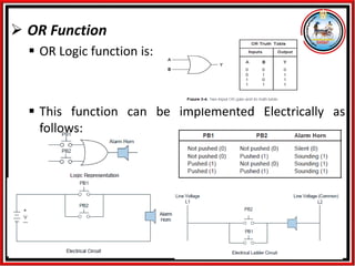
  • 5. ➢ OR Function ▪ OR Logic function is: ▪ This function can be implemented Electrically as follows:
  • 6. ➢ NOT Function ▪ NOT Logic function is: ➢ Control Relay (CR) ▪ A Control Relay (CR) is an electromechanical device which has a coil that functions as an electrical magnet. When this coil is energized it pulls mechanical contacts to connect and disconnect electrical circuits.
  • 7. ➢ Control Relay (CR) (continue) ▪ Normally Closed contact (NC): A contact is normally closed when it is in ON (closed) state when it is in inactivated condition. Consequently, it opens when it is activated. ▪ Normally Open contact (NO): A contact is normally open when it is in an OFF (open) state when it is in inactivated condition. Consequently, it closed when it is activated. NC NO
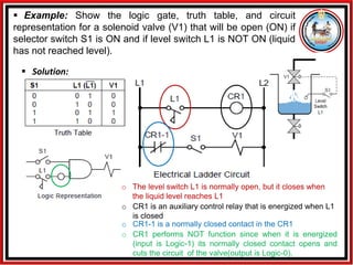
  • 8. ▪ Solution: o The level switch L1 is normally open, but it closes when the liquid level reaches L1 o CR1 is an auxiliary control relay that is energized when L1 is closed o CR1-1 is a normally closed contact in the CR1 o CR1 performs NOT function since when it is energized (input is Logic-1) its normally closed contact opens and cuts the circuit of the valve(output is Logic-0). ▪ Example: Show the logic gate, truth table, and circuit representation for a solenoid valve (V1) that will be open (ON) if selector switch S1 is ON and if level switch L1 is NOT ON (liquid has not reached level).
  • 9. ▪ Solution: Normally closed PB which performs NOT Function ▪ Example: Show the logic gate, truth table, and circuit representation for an alarm horn that will sound if push button PB1 is 1 (ON or depressed) and PB2 is NOT 0 (not depressed).
  • 10. ➢ PLC Circuits NC Over Load Contacts NO auxiliary contact closes when the motor is ON Hardwired rung (network) PLC software implementation Output Field Devices Input Field Devices PLC Circuit Input Addresses Output Address ▪Each input point has an address which refers to a certain bit in the memory that stores the status of this input (1 or 0). ▪Each output point has an address that stores the program result that is reflected on the real field. If the stored value is 1 this point is activated and vice versa. ▪The PLC program reads the inputs from the input dedicated memory using the input addresses and writes the results in the output memory by pointing to it using output address. ▪ Each circuit that controls a certain individual output is called rung or network.
  • 11. ▪ Example Limit Switch Pilot Light Input Field Devices Output Field Devices PLC software implementation Wiring to the I/O (Input-Output) Modules
  • 12. ➢ Some Symbols used in PLC Programs ▪PLC programs are built in the form of virtual control circuit that resembles real electrical control circuits. Normally open contact. This is a virtual contact in the PLC program representing an input to the I/O module of the PLC. If the input is receiving a signal from the field (sensor or switch) this virtual contact closes and passes the signal to control circuit. Normally closed contact. This is a virtual contact in the PLC program representing an input to the I/O module of the PLC. If the input is not receiving a signal from the field (sensor or switch) this virtual contact is closed and passes the signal to control circuit. I case of Applying a signal to the input this contact opens and cuts the control circuit. Output. This is a coil of a virtual relay representing an output in I/O module of the PLC or an internal virtual output. This coil is energized or de-energized from the PLC program which is built in the form of virtual control circuit. When this coil is energized the corresponding point is energized. In addition virtual contacts of this virtual relay can be further used in the rest of the program.
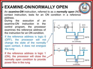
  • 13. ➢EXAMINE-ON/NORMALLY OPEN 0210 0210 ▪ An examine-ON instruction, referred to as a normally open (NO) contact instruction, tests for an ON condition in a reference address. ▪ During the execution of an examine-ON instruction in the control program, the processor examines the reference address of the instruction for an ON condition. ▪ If the reference address is logic 0 (OFF), the processor will not change the state of the normally open contact, it does not energize the rung ▪ If the reference address is logic 1 (ON), the processor will close the normally open condition to provide power flow in the rung
  • 14. ➢EXAMINE-OFF/NORMALLY CLOSED 0210 0210 ▪ An examine-OFF instruction, also called a normally closed (NC) contact instruction, tests for an OFF condition in the reference address ▪ During the execution of an examine- OFF instruction, the processor examines the reference address for an OFF condition. ▪ If the reference address has a logic 0 status (OFF), the instruction will continue to provide power (continuity) through the normally closed contacts ▪ If the reference address has a logic 1 status (ON), the instruction will open the normally closed contact, thus breaking continuity to the rung ▪ An examine-OFF instruction can be associated with a logic NOT function, so that if the reference address is NOT ON, logic continuity will be provided.
  • 15. 0310 0310 ➢ OUTPUT COIL ▪ An output coil instruction controls either a real output (connected to the PLC via output interfaces) or an internal output (control relay). ▪ During the execution of an output coil instruction, the processor evaluates all the input conditions in the ladder rung ▪ If no continuity exists, the processor places a 0 in the output coil address bit, indicating an OFF condition to the output coil instruction ▪ if the processor detects continuity in any path, the processor places a logic 1 in the output coil address bit referenced by the instruction. This logic 1 status indicates an ON condition to the output coil instruction.
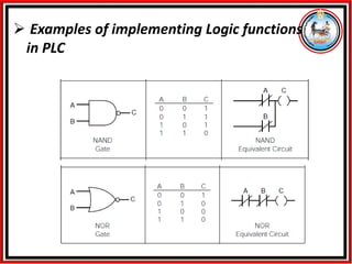
  • 16. ➢ Examples of implementing Logic functions in PLC
  • 17. ➢ Examples of implementing Logic functions in PLC