SlideShare a Scribd company logo
Load Transfer Mechanism
Fig. gives a single
pile of uniform
diameter d
(circular or any
other shape) and
length L driven
into a
homogeneous
mass of soil of
known physical
properties. A
static vertical load
is
applied on the top.
It is required to
determine the
ultimate bearing
capacity Qu of the
pile.
Load carrying capacity of piles
A pile foundation should be safe against shear
failure
Settlement should be within the permissible limits
Four different categories to measure the load
carrying capacity of piles
Static methods
Dynamic formulas
In-situ penetration tests
Pile load tests
Static Formula
Ultimate load capacity of individual pile or group of piles
(Group pile) (Qu)
Depending upon characteristics of the soil
Qu=Qp+Qs
Qu=Ultimate failure load
Qp=Point resistance of the pile
Qs= Shaft resistance developed by friction between the soil
and pile
Load (Q)
Qp
QsQs
Static Analysis
Qf= Qb + Qs
Where Qf = Net ultimate pile load or the
load which can be supported
by a pile top at failure.
Qb = Net load carried by the pile
base or total base resistance.
Qs = The load carried by the pile
shaft or total shaft resistance
Or Qf = fb x Ab + fs x As
Point Resistance Qp
Qp=Point resistance of the pile
Qp= qp x Ap
qp=Ultimate bearing capacity of the soil
Ap= Area of the pile tip (Generally circular)
Load (Q)
Qp
For square foundation
γ
γ
γγ
γ
BNNDq
BNqNq
qfu
qu
4.0
4.0
+=
+=
γγγ BNNDq qfu 3.0+=
For circular foundation
Shallow foundations in sand
Meyerhof’s Method
In case of Sand
Meyerhof’s Method
It has been established that the effective vertical
pressure (q) at the pile tip increases with depth
only until a certain depth (Critical Depth Dc)
q
Dc
Depth
q=γxD
In Pile Foundation
Critical depth depends upon the angle of internal
friction and width or diameter of the pile
(Charts available)
Dc/B
ɸ
Critical depth can roughly be taken as 10 B for
loose sands and 20 B for dense sands
Load carrying capacity of piles
For square foundation
γ
γ
γγ
γ
BNNDq
BNqNq
qcp
qp
4.0
4.0
+=
+=
γγγ BNNDq qcp 3.0+=
For circular foundation
Pile foundations in sand
q=Effective vertical
pressure at the pile tip
γ=Unit weight of the
soil in the zone of pile
tip
Dc=Critical depth
Nq and Nγ= Bearing
capacity factors for
deep foundation
(Charts available)
B= Pile width or
diameter
For square foundation
γγγ BNNDq qcp 4.0+=
γγγ BNNDq qcp 3.0+=
For circular foundation
Pile foundations in sand
q=Effective vertical
pressure at the pile tip
γ=Unit weight of the
soil in the zone of pile
tip
Dc=Critical depth
Nq and Nγ= Bearing
capacity factors for
deep foundation
(Charts available)
B= Pile width or
diameter
For square foundation
qcp NDq γ=
qcp NDq γ=
For circular foundation
Pile foundations in sand
q=Effective vertical
pressure at the pile tip
γ=Unit weight of the
soil in the zone of pile
tip
Dc=Critical depth
Nq and Nγ= Bearing
capacity factors for
deep foundation
(Charts available)
B= Pile width or
diameter
Load carrying capacity of piles
Meyerhof’s method for qp
QP=ApxqxNq ≤ Apxql
ql (kN/m2)=limiting stress=50xNqxtanɸ ≤11000 kPa (110 t/ft2)
qNq≤ ql
Be careful for critical parameters
q=effective vertical pressure at pile tip = γxDc
Nq values
Assumed that the soil above the pile tip is similar
to the soil below the pile tip
If pile penetrates the above hard or compact
stratum only slightly and soil above the pile tip is
loose stratum….then…..
It would be more appropriate to use the value
of Nq for a shallow foundation
Meyerhof’s method for qp
The point bearing capacity (qp) of pile generally
increases with the depth of embedment (Db) in
the bearing stratum
Load (Q)
Qp
G.L
Loose
stratum
Bearing
stratum Db
Meyerhof’s method for qp
Load (Q)
Qp
G.L
Loose
stratum
Bearing
stratum Db
Db reaches to a maximum value at
an embedment ratio of (Db/B)cr
Critical ratio (Db/B)cr depends upon soil friction angle
Determine Nq
If
Load (Q)
Qp
G.L
Loose
stratum
Bearing
stratum
Db<10B
kPaqD
B
qq
qq lb
ll
lp 11000
10
)2(
)1()2(
)1( ≤≤
−
+=
Db=Depth of penetration in dense sand
ql(1)=limiting unit point resistance of loose
sand=50Nq1tanɸ1(kN/m2)
ql(2)=limiting unit point resistance of dense
sand=50Nq2tanɸ2(kN/m2)
Db=Depth of penetration in dense sand
( )
( )
( )depthscouringoranyifsoilweakinportiondeducting
sandwithinembededactuallylengthdepthPileL
esubmergencand
pressureoverburdenforcorrected
basepile
ofvicinitytheinSPTofvalueNAverageN
siltsplasticNonkPaN
SandskPaN
B
L
Nq
p
p
p
,
)(
point)pilethebelowDia4andaboveDia10About(
300
40040
=






=
≤
≤=
qp(gross)=cNc + qNq
q =vertical stress=(γxDf)
for ɸ=0, Nq=1
qp(gross)=cNc + q
qp(net)=cNc
Qp=cNcxAp
c=Cohesion
Nc=Bearing capacity factor for deep foundation
Generally 9.0 for pile (but vary in some cases)
For Clay
( )
4/
0.9
.
resistanceBase
≥
=
=
==
BLwhere
astakengenerally
factorcapacitybearingpileN
undrainedbasebelowcohesionc
Ncf
p
cp
cpb
Analysis of pile capacity in clay
Where qp= fb = unit base resistance
qs= fs = unit skin friction or unit shaft
resistance
Ab = Area of pile base (depends upon
the shape)
As = Surface area of pile shaft.
Pile Capacity in Sand (Effective stress method)
(((( ))))
depthcriticalD
D.pileoflengthEmbeddedEffectiveL
pileforforfactorcapacityBearingN
)pileofbase(pileoftipatpressureoverburdenEffective
)casesallfor(
ft/torkPaNLNf
C
Cp
qp
o
qppqpob
====
≤≤≤≤====
====
====′′′′
≤≤≤≤′′′′====′′′′====
φ
σ
γσ 2
11011000
Skin Resistance Qs
Qs=Shaft resistance developed by friction
between the soil and pile
Qs=fsxAs
fs=Cumulative average unit friction
between the sand and the pile surface
As=Effective surface area of the pile in
contact with the soil (Perimeter X Length)
Load (Q)
QsQs
Floating
fs=Average unit friction between the sand and the
pile surface
Ω= tan
'
vs Kf σ
K= Coefficient of earth pressure
σv
’= Effective vertical pressure at the depth under
consideration
=Coefficient of friction between soil and pile material
(critical depth=15 Dia of Pile), after that frictional resistance
remain constant
≈ 20-15 Dia
4.01.50.67 ɸTimber
2.01.00.75 ɸConcrete
1.00.520oSteel
K
(Dense
sand)
K
(Loose
sand)
Pile
material
(((( ))))
Cssm
s
s
smsss
DbelowandatfofvalueMaximumf
.pileandsandbetweenfrictionofAngle
shaftpilealongpressureoverburdeneffectiveAverage
shaftpileonpressureearthoftcoefficienAverageKWhere
casesallfor
ft/tonkPaftankf
====
====
====′′′′
====
====≤≤≤≤≤≤≤≤′′′′====
δ
σ
δσ 2
1100
The values of DC /B , Ks , tanδδδδ and Nqp (SAA !978)
State Density
Index
ID
DC
/B
Ks tanδδδδ Nqp
Drive
n
Piles
Bore
d
Piles
Driven
Piles
Bored
piles
Loose 0.2-0.4 6 0.8 0.3 60 25
Mediu
m
0.41-
0.75
8 1.0 0.5 100 60
Dense 0.76-0.9 15 1.5 0.8 180 100
Qs for driven piles in clay
Qs=Shaft resistance developed by friction
between the soil and pile
Qs=fsxAs
fs=αc’
c’=Cumulative average cohesion along the pile shaft
α=adhesion factor (Adhesion factor depends upon cohesion
of soil)
Charts available
α METHOD
Load carrying capacity of piles
Qs=Shaft resistance developed by friction
between the soil and pile
Qs=fsxAs
fs=ʎ(σv’+2c) [Vijayvergiya and Fochit (1972)]
c=cohesion of soil
ʎ=friction capacity factor (Friction capacity factor depends
upon embedment length)
Charts available
ʎ METHOD
Load carrying capacity of piles
Care while calculating C and C’
Clay gets remolded while pile is driven
Remolding factor must be taken in account
Remolded strength must always be less than the
undisturbed strength
Strength improves with time
Rate of gain of strength depends upon
Consolidation characteristics
Rate of dissipation of excess pore water pressure
.
5.00.1
.45.0
100
pilesdrivenofcasein
claystiffforandclayssoftfor
pilesboredforfactorAdhesion
kPacffrictionSkin avs
=
===
≤==
α
α
Analysis of pile capacity in clay
From CPT (Plastic soils like clay)
(((( ))))
m.Bfor
m.Bfor.safetyoffactoruseloadAllowable
N
C.C.Ofor.
C.C.Nfor
N
q
f
N
N
N
q
Nf
k
o
o
k
avc
os
k
cp
k
c
cpb
503
5052
20
50
1
20
9
>>>>
≤≤≤≤
====
====
========
≅≅≅≅====
====××××====
α
αα
Method Based on CPT (for driven
piles) (Non Plastic soils like sand)
siltplasticNon
q
sand
q
f
qf
avc
avc
s
cb
150
200
====
====
====
Allowable load: apply Factor
of safety 2.5-3.0
Methods based on SPT (Empirical
relationship)
Driven Piles (By Meyerhof,
C.G.Manual)
(((( ))))
Csb
CpCpsC
s
ba
psb
Cpp
s
ba
Datcalculatedarefandf
DLforDLBfBD
fB
fQ
or
Latcalculatedarefandf
DLforBL
fB
fQ
≥≥≥≥





−−−−++++





++++





××××====
≤≤≤≤











++++





××××====
ππ
π
π
π
243
1
243
1
2
2
Bored Piles
For Bored Piles
( )
4:
2
2
1
2
1
40
3
1
3
1
safetyoffactorApplyLoadAllowable
kPaNpilesDrivenoff
B
L
Npiledrivenofrdf
avs
p
b
==
==
The load carrying capacity of bored piles can
be determined using the same procedure as
that of driven piles
The values of soil parameters are different
between driven and bored piles
Bored piles in sand
Ultimate load capacity of individual pile or group of piles
(Group pile) (Qu)
Depending upon characteristics of the soil
Qu=Qp+Qs
Qu=Ultimate failure load
Qp=Point resistance of the pile
Qs= Shaft resistance developed by friction between the soil
and pile
Load (Q)
Qp
QsQs
Bored piles in sand
( )∑=
Ω+=
n
i
ispqu AvKANqQ
1
''
)(tanσ
Qp Qs
q’ and σv
’= Effective vertical pressure, limited to a
maximum value given by critical depth
K= Lateral earth pressure coefficient for bored foundation
tan =coefficient of friction between soil and pile material
K=1-sinɸ Approximate value
K generally varies between 0.3 and 0.75
An average value of 0.5 is usually adopted
K values
tan values
Can be taken equal to tanɸ for bored piles excavated in
dry soil
If slurry is used while excavation value of tan will
reduced
In general, for a given value of ɸ, bored piles
have a unit point resistance of 1/2 to 2/3 of
that of corresponding driven piles
Why???
In driven piles there is densification
Ultimate load capacity of individual pile or group of piles
(Group pile) (Qu)
Depending upon characteristics of the soil
Qu=Qp+Qs
Qu=Ultimate failure load
Qp=Point resistance of the pile
Qs= Shaft resistance developed by friction between the soil
and pile
Load (Q)
Qp
QsQs
Static method for bored piles in clay
Bored piles in clay
''
spcu AcAcNQ α+=
Qp Qs
As’=Area of shaft that is effective in developing skin
friction
Value of α
Pile type
Method of drilling
For straight shafts
α=0.5 in dry soils without slurry
α=0.3 in dry soils with slurry
For belled shafts
α=0.3 in dry soils without slurry
α=0.15 in dry soils with slurry
Effective area of shaft for skin friction (As’)
Depends upon embedded length of shaft in soil that is
effective in developing skin friction
The lower 1.5 m (or 2B) and top 1.5 m (or 2B) is
neglected
Why?
Because of the disturbance
Generally, for bored piles installed in stiff clay
C=0.75 C (obtained from Triaxial test)
Negative Skin Friction
When soil layer
surrounding the
portion of the
pile shaft settles
more than pile
A downward
drag occurs on
the pile
The drag is
known as
negative skin
friction
Extra
downward
load on pile
nsfuu QQQ −='
Negative Skin Friction
Qu’= net ultimate load
Qnsf= Drag down fce
Qnsf is computed using the same method as we
discussed for the positive frictional resistance
Pile Load Test
Most Reliable Method
Full Scale Static Load Tests
Pile Load Test Setup
Burjis are very commn in
Pakistan
Pile Load Test
Sand bag loading is very common practice
in Pakistan
In case of burjis generally ground is
excavated to install the hydraulic jack and
dial gauges (to measure settlement)
Calibration of dial gauges and hydraulic jack
(loading gauge) must be conducted before test
Pile Load Test Setup
3B or
2.5 m
When pile load test shall be conducted
3 days after installation in sandy soils
One month after installation in silts
and clays (soft clays)
How shall be the application of load
Equal increments of about 20% of the
allowable load (Load at which pile will be
tested)
(Test load= Twice the safe load or the
load at which the total settlement reaches
the specified value
How to record settlement
At least with three dial gauges
When to increase/change the load
Rate of movement of the pile top is not
more than
0.1 mm/hour for sandy soils
0.02 mm/hour for clayey soils
Two hours maximum
Time interval to observe settlement
0.5 min, 1 min, 2 min, 4 min, 8 min, 15
min, 30 min, 1 hour and 2 hours
The last stage of loading will be
continued for 24 hours or even more
depending upon the settlement
How to remove the load
With the same increments and 1 hour
interval
Final rebound is recorded for 24 hours
after the entire load has been removed
Typical load-settlement (unload-rebound curve of
a pile test
Sn=St-Se
Safe load??
2/3 of the final load at which total
settlement is 12 mm
2/3 of the load corresponding to a net
settlement of 6 mm
1/2 of load corresponding to a total
settlement of (B/10) (7.5% incase of under-
reamed pile)
The least of below
The limiting criteria (sometimes
specified)
Under the total load (twice the safe
load)
The net settlement should not be
more than 20 mm
The gross settlement should not be
more than 25 mm
To construct a pre-stressed bridge, a 30
cm diameter pile of length 12 m was
subjected to a pile load test and the
following results were obtained.
Determine the allowable load
6.05.85.55.24.64.0Settlement during
unloading (cm)
6.03.82.551.650.850Settlement during
loading (cm)
25002000150010005000Load (kN)
Load carrying capacity of piles

More Related Content

PDF
Problems on bearing capacity of soil
PPTX
Numerical problem and solution on pile capacity (usefulsearch.org) ( usefuls...
PPTX
PILE foundation (1).pptx
PDF
Problems on piles and deep footing
PPTX
Earth pressure( soil mechanics)
PPTX
Earth pressure
PPTX
Pile load test
PDF
Lecture 7 stress distribution in soil
Problems on bearing capacity of soil
Numerical problem and solution on pile capacity (usefulsearch.org) ( usefuls...
PILE foundation (1).pptx
Problems on piles and deep footing
Earth pressure( soil mechanics)
Earth pressure
Pile load test
Lecture 7 stress distribution in soil

What's hot (20)

PDF
Consolidation of Soil
PDF
Stability of Slopes
PDF
Bearing capacity of shallow foundations by abhishek sharma
PPSX
Geotechnical Engineering-II [Lec #11: Settlement Computation]
PPSX
Geotechnical Engineering-I [Lec #17: Consolidation]
PDF
Lecture 2 bearing capacity
PDF
Lecture 5 soil compaction
PPTX
Bearing capacity theory is code ,vesic ,hansen, meyerhof, skemptons( usefulse...
PDF
TERZAGHI’S BEARING CAPACITY THEORY
PPTX
PPTX
Shear strength of soil
PPTX
Consolidation Properties
PPTX
Stresses in soil
PPTX
Case study on effect of water table on bearing capacity
PPSX
Geotechnical Engineering-II [Lec #26: Slope Stability]
PPTX
Standard penetration test (spt)
PDF
Grouting Methods
PPTX
Sums on Rigid Pavement Design
PPTX
Numerical problem on bearing capacity is code terzaghi water table (usefulsea...
Consolidation of Soil
Stability of Slopes
Bearing capacity of shallow foundations by abhishek sharma
Geotechnical Engineering-II [Lec #11: Settlement Computation]
Geotechnical Engineering-I [Lec #17: Consolidation]
Lecture 2 bearing capacity
Lecture 5 soil compaction
Bearing capacity theory is code ,vesic ,hansen, meyerhof, skemptons( usefulse...
TERZAGHI’S BEARING CAPACITY THEORY
Shear strength of soil
Consolidation Properties
Stresses in soil
Case study on effect of water table on bearing capacity
Geotechnical Engineering-II [Lec #26: Slope Stability]
Standard penetration test (spt)
Grouting Methods
Sums on Rigid Pavement Design
Numerical problem on bearing capacity is code terzaghi water table (usefulsea...
Ad

Similar to Load carrying capacity of piles (20)

PDF
137518876 bearing-capacity-from-spt
PDF
241 footing &amp; piling bearing capacities
PPTX
Pile Foundationsvjhvjvgyujgvuyjgiugiug.pptx
PDF
Unisoft software bengt h. fellenius, pierre goudrault
PDF
Geotechnical Problems of Bearing capcity of shallow foundation
PDF
Geotechnical Problems of Bearing capcity of shallow foundation
PPT
Parameter for pile deisgns
PPT
Parameter for pile design
PPTX
BEARING CAPACITY C.pptx
PPTX
Numerical Question on Terzaghi Bearing Capacity Theory, Meyerhof Bearing Capa...
PPTX
CVEN 440_540 Classnotes (6) --- Static analysis of pile foundation.pptx
PPSX
Geotechnical Engineering-I [Lec #19: Consolidation-III]
PDF
Lecture 1. bearing capacity of soil
PDF
1 shear strength
PPTX
L3-Part-1 sdsasad sad asdsac asdasd.pptx
PDF
기초공학 - 11-2 Pile Foundations.pdf
PPSX
Geotechnical Engineering-II [Lec #28: Finite Slope Stability Analysis]
PPTX
Civil Pile Foundation ppt.pptx
PPTX
Civil pile
PPTX
Bearing capacity of soil that reflects the strength of foundation.pptx
137518876 bearing-capacity-from-spt
241 footing &amp; piling bearing capacities
Pile Foundationsvjhvjvgyujgvuyjgiugiug.pptx
Unisoft software bengt h. fellenius, pierre goudrault
Geotechnical Problems of Bearing capcity of shallow foundation
Parameter for pile deisgns
Parameter for pile design
BEARING CAPACITY C.pptx
Numerical Question on Terzaghi Bearing Capacity Theory, Meyerhof Bearing Capa...
CVEN 440_540 Classnotes (6) --- Static analysis of pile foundation.pptx
Geotechnical Engineering-I [Lec #19: Consolidation-III]
Lecture 1. bearing capacity of soil
1 shear strength
L3-Part-1 sdsasad sad asdsac asdasd.pptx
기초공학 - 11-2 Pile Foundations.pdf
Geotechnical Engineering-II [Lec #28: Finite Slope Stability Analysis]
Civil Pile Foundation ppt.pptx
Civil pile
Bearing capacity of soil that reflects the strength of foundation.pptx
Ad

More from Latif Hyder Wadho (20)

PPTX
Internal Control Internal Checking Internal Auditing - Auditing By LATiFHRW
PPTX
Supply and Demand - Modern Economics LATiFHRW
PPTX
Surveying and Leveling
PPTX
Energy crisis in Pakistan
PDF
SPSC PCS Syllabus cce 2018
DOCX
SPSC CCE 2013 Pcs past papers
DOCX
SPSC CCE 2013 Pcs screening test
PPS
Engineering drawing
DOCX
Why is english as a global language
DOCX
PPT
Introduction to Geo technical Engineering 2
PPT
Introdction to Geo technical Engineering
PDF
Sub surface exploration part 2
PDF
Settlement of piles
PDF
Plate load test
PDF
Subsurface exploration (part-3)
PDF
Sub surface exploration (part-1)
PDF
Introduction to Foundation Engineering
PDF
Review of soil mechanics
PDF
Subsurface exploration of soil
Internal Control Internal Checking Internal Auditing - Auditing By LATiFHRW
Supply and Demand - Modern Economics LATiFHRW
Surveying and Leveling
Energy crisis in Pakistan
SPSC PCS Syllabus cce 2018
SPSC CCE 2013 Pcs past papers
SPSC CCE 2013 Pcs screening test
Engineering drawing
Why is english as a global language
Introduction to Geo technical Engineering 2
Introdction to Geo technical Engineering
Sub surface exploration part 2
Settlement of piles
Plate load test
Subsurface exploration (part-3)
Sub surface exploration (part-1)
Introduction to Foundation Engineering
Review of soil mechanics
Subsurface exploration of soil

Recently uploaded (20)

PPTX
MCN 401 KTU-2019-PPE KITS-MODULE 2.pptx
PDF
Mitigating Risks through Effective Management for Enhancing Organizational Pe...
PDF
July 2025 - Top 10 Read Articles in International Journal of Software Enginee...
PPTX
CH1 Production IntroductoryConcepts.pptx
PDF
Structs to JSON How Go Powers REST APIs.pdf
PPTX
Lesson 3_Tessellation.pptx finite Mathematics
PPTX
MET 305 2019 SCHEME MODULE 2 COMPLETE.pptx
PPTX
KTU 2019 -S7-MCN 401 MODULE 2-VINAY.pptx
PPTX
IOT PPTs Week 10 Lecture Material.pptx of NPTEL Smart Cities contd
PPTX
web development for engineering and engineering
PPTX
Sustainable Sites - Green Building Construction
PPTX
Construction Project Organization Group 2.pptx
PDF
composite construction of structures.pdf
PPTX
Lecture Notes Electrical Wiring System Components
PPTX
Internet of Things (IOT) - A guide to understanding
PPTX
Foundation to blockchain - A guide to Blockchain Tech
PPTX
FINAL REVIEW FOR COPD DIANOSIS FOR PULMONARY DISEASE.pptx
PPTX
Recipes for Real Time Voice AI WebRTC, SLMs and Open Source Software.pptx
PDF
BMEC211 - INTRODUCTION TO MECHATRONICS-1.pdf
PPTX
Engineering Ethics, Safety and Environment [Autosaved] (1).pptx
MCN 401 KTU-2019-PPE KITS-MODULE 2.pptx
Mitigating Risks through Effective Management for Enhancing Organizational Pe...
July 2025 - Top 10 Read Articles in International Journal of Software Enginee...
CH1 Production IntroductoryConcepts.pptx
Structs to JSON How Go Powers REST APIs.pdf
Lesson 3_Tessellation.pptx finite Mathematics
MET 305 2019 SCHEME MODULE 2 COMPLETE.pptx
KTU 2019 -S7-MCN 401 MODULE 2-VINAY.pptx
IOT PPTs Week 10 Lecture Material.pptx of NPTEL Smart Cities contd
web development for engineering and engineering
Sustainable Sites - Green Building Construction
Construction Project Organization Group 2.pptx
composite construction of structures.pdf
Lecture Notes Electrical Wiring System Components
Internet of Things (IOT) - A guide to understanding
Foundation to blockchain - A guide to Blockchain Tech
FINAL REVIEW FOR COPD DIANOSIS FOR PULMONARY DISEASE.pptx
Recipes for Real Time Voice AI WebRTC, SLMs and Open Source Software.pptx
BMEC211 - INTRODUCTION TO MECHATRONICS-1.pdf
Engineering Ethics, Safety and Environment [Autosaved] (1).pptx

Load carrying capacity of piles

  • 1. Load Transfer Mechanism Fig. gives a single pile of uniform diameter d (circular or any other shape) and length L driven into a homogeneous mass of soil of known physical properties. A static vertical load is applied on the top. It is required to determine the ultimate bearing capacity Qu of the pile.
  • 2. Load carrying capacity of piles A pile foundation should be safe against shear failure Settlement should be within the permissible limits Four different categories to measure the load carrying capacity of piles Static methods Dynamic formulas In-situ penetration tests Pile load tests
  • 3. Static Formula Ultimate load capacity of individual pile or group of piles (Group pile) (Qu) Depending upon characteristics of the soil Qu=Qp+Qs Qu=Ultimate failure load Qp=Point resistance of the pile Qs= Shaft resistance developed by friction between the soil and pile Load (Q) Qp QsQs
  • 4. Static Analysis Qf= Qb + Qs Where Qf = Net ultimate pile load or the load which can be supported by a pile top at failure. Qb = Net load carried by the pile base or total base resistance. Qs = The load carried by the pile shaft or total shaft resistance Or Qf = fb x Ab + fs x As
  • 6. Qp=Point resistance of the pile Qp= qp x Ap qp=Ultimate bearing capacity of the soil Ap= Area of the pile tip (Generally circular) Load (Q) Qp
  • 7. For square foundation γ γ γγ γ BNNDq BNqNq qfu qu 4.0 4.0 += += γγγ BNNDq qfu 3.0+= For circular foundation Shallow foundations in sand Meyerhof’s Method In case of Sand
  • 8. Meyerhof’s Method It has been established that the effective vertical pressure (q) at the pile tip increases with depth only until a certain depth (Critical Depth Dc) q Dc Depth q=γxD
  • 9. In Pile Foundation Critical depth depends upon the angle of internal friction and width or diameter of the pile (Charts available) Dc/B ɸ Critical depth can roughly be taken as 10 B for loose sands and 20 B for dense sands
  • 11. For square foundation γ γ γγ γ BNNDq BNqNq qcp qp 4.0 4.0 += += γγγ BNNDq qcp 3.0+= For circular foundation Pile foundations in sand q=Effective vertical pressure at the pile tip γ=Unit weight of the soil in the zone of pile tip Dc=Critical depth Nq and Nγ= Bearing capacity factors for deep foundation (Charts available) B= Pile width or diameter
  • 12. For square foundation γγγ BNNDq qcp 4.0+= γγγ BNNDq qcp 3.0+= For circular foundation Pile foundations in sand q=Effective vertical pressure at the pile tip γ=Unit weight of the soil in the zone of pile tip Dc=Critical depth Nq and Nγ= Bearing capacity factors for deep foundation (Charts available) B= Pile width or diameter
  • 13. For square foundation qcp NDq γ= qcp NDq γ= For circular foundation Pile foundations in sand q=Effective vertical pressure at the pile tip γ=Unit weight of the soil in the zone of pile tip Dc=Critical depth Nq and Nγ= Bearing capacity factors for deep foundation (Charts available) B= Pile width or diameter
  • 15. Meyerhof’s method for qp QP=ApxqxNq ≤ Apxql ql (kN/m2)=limiting stress=50xNqxtanɸ ≤11000 kPa (110 t/ft2) qNq≤ ql Be careful for critical parameters q=effective vertical pressure at pile tip = γxDc
  • 16. Nq values Assumed that the soil above the pile tip is similar to the soil below the pile tip If pile penetrates the above hard or compact stratum only slightly and soil above the pile tip is loose stratum….then….. It would be more appropriate to use the value of Nq for a shallow foundation
  • 17. Meyerhof’s method for qp The point bearing capacity (qp) of pile generally increases with the depth of embedment (Db) in the bearing stratum Load (Q) Qp G.L Loose stratum Bearing stratum Db
  • 18. Meyerhof’s method for qp Load (Q) Qp G.L Loose stratum Bearing stratum Db Db reaches to a maximum value at an embedment ratio of (Db/B)cr Critical ratio (Db/B)cr depends upon soil friction angle Determine Nq
  • 19. If Load (Q) Qp G.L Loose stratum Bearing stratum Db<10B kPaqD B qq qq lb ll lp 11000 10 )2( )1()2( )1( ≤≤ − += Db=Depth of penetration in dense sand
  • 20. ql(1)=limiting unit point resistance of loose sand=50Nq1tanɸ1(kN/m2) ql(2)=limiting unit point resistance of dense sand=50Nq2tanɸ2(kN/m2) Db=Depth of penetration in dense sand
  • 21. ( ) ( ) ( )depthscouringoranyifsoilweakinportiondeducting sandwithinembededactuallylengthdepthPileL esubmergencand pressureoverburdenforcorrected basepile ofvicinitytheinSPTofvalueNAverageN siltsplasticNonkPaN SandskPaN B L Nq p p p , )( point)pilethebelowDia4andaboveDia10About( 300 40040 =       = ≤ ≤=
  • 22. qp(gross)=cNc + qNq q =vertical stress=(γxDf) for ɸ=0, Nq=1 qp(gross)=cNc + q qp(net)=cNc Qp=cNcxAp c=Cohesion Nc=Bearing capacity factor for deep foundation Generally 9.0 for pile (but vary in some cases) For Clay
  • 24. Where qp= fb = unit base resistance qs= fs = unit skin friction or unit shaft resistance Ab = Area of pile base (depends upon the shape) As = Surface area of pile shaft. Pile Capacity in Sand (Effective stress method) (((( )))) depthcriticalD D.pileoflengthEmbeddedEffectiveL pileforforfactorcapacityBearingN )pileofbase(pileoftipatpressureoverburdenEffective )casesallfor( ft/torkPaNLNf C Cp qp o qppqpob ==== ≤≤≤≤==== ==== ====′′′′ ≤≤≤≤′′′′====′′′′==== φ σ γσ 2 11011000
  • 26. Qs=Shaft resistance developed by friction between the soil and pile Qs=fsxAs fs=Cumulative average unit friction between the sand and the pile surface As=Effective surface area of the pile in contact with the soil (Perimeter X Length) Load (Q) QsQs Floating
  • 27. fs=Average unit friction between the sand and the pile surface Ω= tan ' vs Kf σ K= Coefficient of earth pressure σv ’= Effective vertical pressure at the depth under consideration =Coefficient of friction between soil and pile material (critical depth=15 Dia of Pile), after that frictional resistance remain constant
  • 30. (((( )))) Cssm s s smsss DbelowandatfofvalueMaximumf .pileandsandbetweenfrictionofAngle shaftpilealongpressureoverburdeneffectiveAverage shaftpileonpressureearthoftcoefficienAverageKWhere casesallfor ft/tonkPaftankf ==== ==== ====′′′′ ==== ====≤≤≤≤≤≤≤≤′′′′==== δ σ δσ 2 1100 The values of DC /B , Ks , tanδδδδ and Nqp (SAA !978) State Density Index ID DC /B Ks tanδδδδ Nqp Drive n Piles Bore d Piles Driven Piles Bored piles Loose 0.2-0.4 6 0.8 0.3 60 25 Mediu m 0.41- 0.75 8 1.0 0.5 100 60 Dense 0.76-0.9 15 1.5 0.8 180 100
  • 31. Qs for driven piles in clay
  • 32. Qs=Shaft resistance developed by friction between the soil and pile Qs=fsxAs fs=αc’ c’=Cumulative average cohesion along the pile shaft α=adhesion factor (Adhesion factor depends upon cohesion of soil) Charts available α METHOD
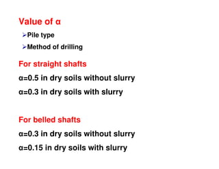
  • 34. Qs=Shaft resistance developed by friction between the soil and pile Qs=fsxAs fs=ʎ(σv’+2c) [Vijayvergiya and Fochit (1972)] c=cohesion of soil ʎ=friction capacity factor (Friction capacity factor depends upon embedment length) Charts available ʎ METHOD
  • 36. Care while calculating C and C’ Clay gets remolded while pile is driven Remolding factor must be taken in account Remolded strength must always be less than the undisturbed strength Strength improves with time Rate of gain of strength depends upon Consolidation characteristics Rate of dissipation of excess pore water pressure
  • 38. From CPT (Plastic soils like clay) (((( )))) m.Bfor m.Bfor.safetyoffactoruseloadAllowable N C.C.Ofor. C.C.Nfor N q f N N N q Nf k o o k avc os k cp k c cpb 503 5052 20 50 1 20 9 >>>> ≤≤≤≤ ==== ==== ======== ≅≅≅≅==== ====××××==== α αα
  • 39. Method Based on CPT (for driven piles) (Non Plastic soils like sand) siltplasticNon q sand q f qf avc avc s cb 150 200 ==== ==== ==== Allowable load: apply Factor of safety 2.5-3.0
  • 40. Methods based on SPT (Empirical relationship) Driven Piles (By Meyerhof, C.G.Manual) (((( )))) Csb CpCpsC s ba psb Cpp s ba Datcalculatedarefandf DLforDLBfBD fB fQ or Latcalculatedarefandf DLforBL fB fQ ≥≥≥≥      −−−−++++      ++++      ××××==== ≤≤≤≤            ++++      ××××==== ππ π π π 243 1 243 1 2 2
  • 42. For Bored Piles ( ) 4: 2 2 1 2 1 40 3 1 3 1 safetyoffactorApplyLoadAllowable kPaNpilesDrivenoff B L Npiledrivenofrdf avs p b == ==
  • 43. The load carrying capacity of bored piles can be determined using the same procedure as that of driven piles The values of soil parameters are different between driven and bored piles
  • 44. Bored piles in sand Ultimate load capacity of individual pile or group of piles (Group pile) (Qu) Depending upon characteristics of the soil Qu=Qp+Qs Qu=Ultimate failure load Qp=Point resistance of the pile Qs= Shaft resistance developed by friction between the soil and pile Load (Q) Qp QsQs
  • 45. Bored piles in sand ( )∑= Ω+= n i ispqu AvKANqQ 1 '' )(tanσ Qp Qs q’ and σv ’= Effective vertical pressure, limited to a maximum value given by critical depth K= Lateral earth pressure coefficient for bored foundation tan =coefficient of friction between soil and pile material
  • 46. K=1-sinɸ Approximate value K generally varies between 0.3 and 0.75 An average value of 0.5 is usually adopted K values tan values Can be taken equal to tanɸ for bored piles excavated in dry soil If slurry is used while excavation value of tan will reduced
  • 47. In general, for a given value of ɸ, bored piles have a unit point resistance of 1/2 to 2/3 of that of corresponding driven piles Why??? In driven piles there is densification
  • 48. Ultimate load capacity of individual pile or group of piles (Group pile) (Qu) Depending upon characteristics of the soil Qu=Qp+Qs Qu=Ultimate failure load Qp=Point resistance of the pile Qs= Shaft resistance developed by friction between the soil and pile Load (Q) Qp QsQs Static method for bored piles in clay
  • 49. Bored piles in clay '' spcu AcAcNQ α+= Qp Qs As’=Area of shaft that is effective in developing skin friction
  • 50. Value of α Pile type Method of drilling For straight shafts α=0.5 in dry soils without slurry α=0.3 in dry soils with slurry For belled shafts α=0.3 in dry soils without slurry α=0.15 in dry soils with slurry
  • 51. Effective area of shaft for skin friction (As’) Depends upon embedded length of shaft in soil that is effective in developing skin friction The lower 1.5 m (or 2B) and top 1.5 m (or 2B) is neglected Why? Because of the disturbance Generally, for bored piles installed in stiff clay C=0.75 C (obtained from Triaxial test)
  • 52. Negative Skin Friction When soil layer surrounding the portion of the pile shaft settles more than pile A downward drag occurs on the pile The drag is known as negative skin friction Extra downward load on pile
  • 53. nsfuu QQQ −=' Negative Skin Friction Qu’= net ultimate load Qnsf= Drag down fce Qnsf is computed using the same method as we discussed for the positive frictional resistance
  • 54. Pile Load Test Most Reliable Method
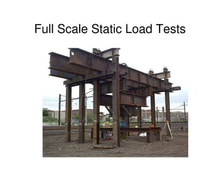
  • 55. Full Scale Static Load Tests
  • 56. Full Scale Static Load Tests
  • 57. Full Scale Static Load Tests
  • 58. Full Scale Static Load Tests
  • 59. Full Scale Static Load Tests
  • 60. Full Scale Static Load Tests
  • 61. Full Scale Static Load Tests
  • 62. Pile Load Test Setup Burjis are very commn in Pakistan
  • 63. Pile Load Test Sand bag loading is very common practice in Pakistan
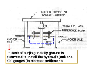
  • 64. In case of burjis generally ground is excavated to install the hydraulic jack and dial gauges (to measure settlement)
  • 65. Calibration of dial gauges and hydraulic jack (loading gauge) must be conducted before test
  • 66. Pile Load Test Setup 3B or 2.5 m
  • 67. When pile load test shall be conducted 3 days after installation in sandy soils One month after installation in silts and clays (soft clays) How shall be the application of load Equal increments of about 20% of the allowable load (Load at which pile will be tested) (Test load= Twice the safe load or the load at which the total settlement reaches the specified value
  • 68. How to record settlement At least with three dial gauges When to increase/change the load Rate of movement of the pile top is not more than 0.1 mm/hour for sandy soils 0.02 mm/hour for clayey soils Two hours maximum
  • 69. Time interval to observe settlement 0.5 min, 1 min, 2 min, 4 min, 8 min, 15 min, 30 min, 1 hour and 2 hours The last stage of loading will be continued for 24 hours or even more depending upon the settlement
  • 70. How to remove the load With the same increments and 1 hour interval Final rebound is recorded for 24 hours after the entire load has been removed
  • 71. Typical load-settlement (unload-rebound curve of a pile test Sn=St-Se
  • 72. Safe load?? 2/3 of the final load at which total settlement is 12 mm 2/3 of the load corresponding to a net settlement of 6 mm 1/2 of load corresponding to a total settlement of (B/10) (7.5% incase of under- reamed pile) The least of below
  • 73. The limiting criteria (sometimes specified) Under the total load (twice the safe load) The net settlement should not be more than 20 mm The gross settlement should not be more than 25 mm
  • 74. To construct a pre-stressed bridge, a 30 cm diameter pile of length 12 m was subjected to a pile load test and the following results were obtained. Determine the allowable load 6.05.85.55.24.64.0Settlement during unloading (cm) 6.03.82.551.650.850Settlement during loading (cm) 25002000150010005000Load (kN)