


![EOW, HDLC 1 (High-Level Data Link Control)
EOW HDLC communication utilities:
64kb/s user channel
Enables a 64kb/s communication channel between the IFUs Supervisor Unit's software and a remote site SU, enabling remote management and configuration/control.
To utilize this operation the HDLC device has to be assigned an IP address and included in the Supervisor software's IP routing table on both ends of this communication
channel, plus directed into a SOH or NOH channel towards a particular antenna direction. The IP-address assignment is done in the configuration-->network menu.
This remote management and configuration/control function is accessable through, as usual, a web-browser and the remote WEB management and configuration service.
The check box "Enable" must be checked for setup of 64kb/s connections.
When SOH / TOH button is pushed, an SOH / TOH matrix is displayed. Available SOH / TOH bytes (white colour) can be selected. The byte will turn yellow indicating that
the byte is selected for 64kb/s traffic.
If the NOH button is pushed, NOH channel 1 or 2 can be selected.
G.703 Co-directional
The check box "Enable" must be checked for setup of G.703 Co-directional connections.
Enables the HDLC device to send data between Port 3 and the SU, which provide two different functions
Terminal-server function
This function provide access to Port 3 from a telnet-connection on the Supervisory Unit. Ex. connect a PC to the SU and start the telnet application on the PC and connect to
the targets IP address and TCP port #. This will then provide some simple means to access and control other devices and units.
The TCP port # is assigned according to the following parameters:
First digit - 3
Second digit - Equal to the IFU number
Third digit - Equal to slot number -7. E.g. Upper left most slot (slot # 7) gives the digit; 7-7=0
Fourth digit - 0
Local Management connection
This is similar to the remote management connection, but the "remote" unit to manage is in the near vicinity - usually in the same room.
E.g.
Web-client <--> PC <--> IFU#1[SU <--> EOW <--> HDLC <---> Port#3] <----- Cross con cable -----> IFU#2 [Port#3 <--> HDLC <---> EOW <--> SU <--> WEB-Service <-->
configuration software <--> IFU Hardware]](https://image.slidesharecdn.com/operationevolution-160307141903/85/Operation-evolution-145-320.jpg)


![Web-client <--> PC <--> IFU#1[SU <--> EOW <--> HDLC <---> Port#3] <----- Cross con cable -----> IFU#2 [Port#3 <--> HDLC <---> EOW <--> SU <-->
WEB-Service <--> configuration software <--> IFU Hardware]
Port 4 - V.11
The check box "Enable" must be checked for setup of V.11 connections.
Enables the HDLC device to send data between Port 4 and the SU, which provide two different functions; Terminal-server function and Local
Management connection.
See G.703 Co-directional description.](https://image.slidesharecdn.com/operationevolution-160307141903/85/Operation-evolution-174-320.jpg)


Operation evolution
- 1. Evolution Series User Manual Operation B4065 Rev. F This manual is the property of Nera Networks AS. No parts of the manual may be copied, rewritten or distributed to third parties without the written permission from Nera Networks AS. In addition to the WEB edition the manual is available in paper format
- 2. The manual is divided in 5 main parts: General Installation Operation Maintenance Appendices This part gives a general overview of the Evolution Series equipment Gives the details on how to install the equipment Describes how to operate the system with emphasis on the Evolution Series Manager Gives details on maintenance of the equipment A collection of frequency plans, alarm lists, technical specifications etc.
- 3. Table of Contents General Installation Operation Evolution Manager General Description Graphical User Interface Configuration Unit Housekeeping Frequency setting IP setting IP configuration via USB DCC setting Password change Add new user Feature Description Menu Details Home Configuration SU Config. RIU Config. FAN Config. LIU Config. LIU 12xE1 Config. LIU 25xE1 Config. LIU 8xT1 Config. LIU 16xT1 Config. LIU 3xDS3/E3 Config. Gigabit Eth Config. DXC Config. EOW Config. 64kb/s Config. Alm & Ctrl Config. E1/T1 Wayside Config. Mother Board ODU Fault Performance Security Maintenance Appendices Click on the to expand the menu Home
- 4. Evolution Manager General Description The Evolution Manager is a web interface of the Network Element. It is used for configuration, testing and monitoring of the Network Element. The Evolution Manager can be accessed from a web browser, or by means of a network element management system, such as “NetMaster”.
- 5. The Evolution Manager has two main navigation elements, the top menu and the equipment view. The content frame will display information as a result of the selections in both menus. This allows for filtering the information in the content frame, by selecting a specific unit in the equipment view. The Evolution Manager has two navigation modes: Graphical User Interface (GUI) A schematic view of the GUI is shown in the figure below:
- 6. “Network Element”: When no units are selected in the equipment view, selections in the top menu will cause information relevant to the Network Element as a whole to be displayed in the content frame. The navigation status will read “Network Element”, and the Evolution Manager is said to be in “Network Element” mode. “Individual Unit”: In contrast, when a specific unit has been selected in the equipment view, selections in the top menu will cause information only relevant to the selected unit to be displayed in the content frame. This mode is called “Individual Unit” mode, and the navigation status will reflect this by displaying the name of the selected unit. In order to break out of “Individual Unit” mode, the “Home” menu option must be selected from the top menu. This brings the Evolution Manager back to “Network Element” mode, and this will be reflected in the navigation status.
- 7. Configuration Unit Housekeeping Whenever changes to the hardware configuration is to be made, the Unit Housekeeping wizard must be run. (E.g. new Interface Units, or a plug-in unit is placed in a new slot in the IFU) . To start the Unit Housekeeping Wizard; Click on Configuration and then Housekeeping. By clicking the same sequence on the figure below, a Unit Housekeeping tutorial will start.
- 8. Housekeeping Wizard Step 1 of 5 - Station Configuration 1. Type Station Name and Terminal Name 2. Select the System Type. The System Type is determined by the license documents 3. Select Transmission Standard Options; ETSI, ANSI or No standard 4. Antenna Directions Possible values; 1 or 2 5. Click Next to proceed Click on the "Next" or "Previous" etc. buttons to navigate in the Housekeeping wizard tutorial.
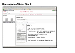
- 9. Housekeeping Wizard Step 2 of 5 - Antenna Configuration 1. Type the Direction Name. Note! If there are more than one Antenna direction, the configuration on this page must be performed for each direction, by clicking "Next" 2. Select Transmission Standard and Capacity according to 2. Select Number of Regular channels 3. Select the desired type of Radio Protection 4. Click Next to proceed or Previous to go back to previous page
- 10. Housekeeping Wizard Step 3 of 5 - IFU Frame Configuration 1. Select Subrack Type. Options: Standalone IFU Select IFU Frame Number. If there are more than one IFU Frame in the subrack, the configuration on this page must be performed on each separately, by clicking "Next" button. IFU Frame Number 1 is the lowest in the subrack. 2. Check this box if a Direct Cross Connect Unit shall be used. 3. When the XPIC checkbox is checked, the radios connected to the current IFU Frame are configured in XPIC mode.
- 11. Housekeeping Wizard Step 4 of 5 - Interface Configuration 1. If all Interface Units in the current IFU Frame are of the same type or there is only one Interface Unit, the Interface Unit can be picked from the list. 2. If there are Interface Units of different type in the current IFU Frame; click on the "Config Indv. Interface" button. Otherwise click "Next" or "Previous" to go back to previous page.
- 12. Housekeeping Wizard Step 4 of 5 - Individual Interface Configuration 1. Click on the slot to be configured. Configurable slots in blue frames. 2. Select an Interface Unit from the List Select the Antenna Direction (if more than one option) and Channel number. Click on the "Add To List" button and the configured slot will appear in the list of Configured Interface Slots. 3. To reconfigure a slot; check the actual checkbox and click the "Remove" button. 4. Click OK to accept or Cancel to leave the current page without changes
- 13. Housekeeping Wizard Step 5 of 5 - Auxiliary Interface Configuration 1. Click on the slot to be configured. Configurable slots in blue frames. 2. Select an Interface Unit from the List Click on the "Add To List" button and the configured slot will appear in the list of Configured Auxiliary Interface Slots. 3. To reconfigure a slot; check the actual checkbox and click the "Remove" button. 4. Click Previous to go back to the Interface Configuration page or Finish to exit the Housekeeping wizard
- 14. Frequency setting To enter the frequency setting page; Click on Configuration and then Frequency. Click the same sequence on the figure below to view the frequency setup page description. 1. Select correct frequency plan from the list. All available frequency plans will be listed. Note! This action can not be performed if the radio is disconnected from the IFU. "Manual Channel Setting" can be selected as an option. 2. Select correct bandwidth from the list. Available options are listed. 4. Click "Set" to accept the changes. 3. Select Tx or Rx frequency from the list (the corresponding Rx or Txfrequency will automatically beselected. This action must be performed on all channels. If "Manual Channel Setting" is selected in step 1, the Tx and Rx frequencies can be typed in manually. Return to Configuration main page by clicking the "Set" button.
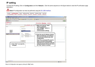
- 15. IP setting To enter the IP setting; Click on Configuration and then Network. Click the same sequence on the figure below to view the IP confiuration page description. Note! IP configuration can also be perforned using the SU USB interface. 1. Make sure that the "eth0" option is selected. (The "DIR0@1" option is used for DCC communication setting) 2. Enter the new IP address, Subnet Mask and Gateway, according to the local area network plan and configuration. Note! The connected PC must be within the same Subnet Mask, otherwise the connection with the network element will be lost when the "Set" button is clicked. 3. Click "Set" to accept the changes. Return to Configuration main page by clicking the "Set" button.
- 16. IP Configuration via USB Hyperterminal is used for connection between the PC USB port and the SU. An USB cable with an USB B plug (for connection to the SU) in one end and an USB A plug (PC side) in the other end. Install drivers q Connect the USB cable to PC and SU q The following picture appears
- 17. q Select "No, not this time" q Click "Next"
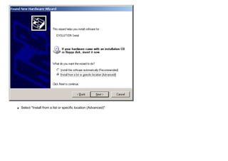
- 18. q Select "Install from a list or specific location (Advanced)"
- 19. q Browse to the "USB_drivers" folder on the "Evolution Series Manual" CD q Click "OK"
- 20. q Click "Next"
- 21. q Select "No, do not connect to the Internet now" q Click "Next"
- 22. q Click "Continue Anyway"
- 23. q Click "Finish" HyperTerminal set-up q Start HyperTerminal from "Start" button as shown below
- 25. q Click "Yes"
- 26. q The options in this dialogue box are not relevant. Click "OK"
- 27. q The options in this dialogue box are not relevant. Click "OK"
- 28. q Type in the name for the connection e.g. "Evolution" and select an optional icon
- 29. q Select the COM port assosiated with the IFU
- 30. q Select options as described above q Click "OK"
- 31. q Hit the "Enter" key on the keyboard
- 33. q Log on using User name and password (default User: "admin", Password: "admin")
- 34. IP Configuration The following parameters can be red or set: q ipconfig q iprange q iprangeset q reloadtask q reset To view current ipconfig, type ipconfig and hit the "Enter" key on the keyboard. Type help and hit the "Enter" key on the keyboard to learn about the available commands.
- 36. Set up of IP radio port (DCC channel) To enter the DCC configuration; Click on Configuration and then Network. Click the same sequence on the figure below to view the DCC configuration page description. For more information see "Management Traffic Routing." 1. Select the "DIR0@#" option. Where "#" determins the RIU number. 2. Check the "Enable" box and type inn the IP address. 3. Click "Set" to accept the changes.
- 37. Password change To enter the Password setting; Click on Security. Click security on the figure below to view the Change Password page description. Step1 Click on the "Change Password" Tab.
- 38. Step2 1. Enter the current password. 2. Enter the new password. (See details below) 3. Confirm the new password. 4. Accept the new password by clicking the save button. Password Length: Possible characters: 8-32 characters (alphanumeric) A-Z, a-z, 0-9 (case sensitive) Warning! When admin password is changed from default (admin); it is not possible for Nera Networks to revert to the old password or provide a new one.
- 39. Add new user To enter the Add New User page; Click on Security. Click security on the figure below to view the Add User page description. Step1 Click "Add User" to proceed
- 40. Step2 1. Type in the new "User Name", "Password" and re-type the selected password. (See details below) 2. Select "Privilege" Alternatives: Passive, Active, Master, Admin. (See details below) Select "Status" Alternatives: Permanent User, Temporary User. If Temporary User is selected; Select Active perriod. Alternatives: 1 to 100 days. 3. Accept the new password by clicking the save button.
- 41. Feature Description A wide range of configuration, tests and system monitoring can be performed by means of the Evolution Manager. The screenshots shown in this chapter and the navigation is the same as in the Evolution Manager program, for a certain equipment configuration. The screenshots in the Evolution Manager will change dynamically with the actual equipment configuration and may differ from this example on certain sub-menus. Note! This is only a tutorial and no parameters can be set from this manual. The alarms and system configuration details are fictive and not related to a "live" system. Menu Details A brief description of the functionallity is shown when the cursor is placed over the menue items or the IFU Frame Plug-in units (including Mother board), in the screenshot below. Click on a menue item or IFU Plug-in unit, to get a detailed description of the specific item. Note! The Mother board is accessed by clicking the yellow bar on the IFU lower part or the grey bar on the top.
- 42. Configuration In the Configuration menu the system can be configured according to user preferences and license parameters. Click on the sub-menues to explore the functionality. For configuration of Plug-in units and ODU, click on the Radio/IFU picture on the screenshot. Note! The Mother board is accessed by clicking the yellow bar on the IFU lower part or the grey bar on the top.
- 43. Housekeeping Wizard Step 1 The Housekeeping wizard must be run initially when the system is set up for the first time and if the hardware configuration has been changed. Note! click the Next, Previous.. etc buttons to navigate in this tutorial.
- 44. Housekeeping Wizard Step 2
- 45. Housekeeping Wizard Step 3 Activation of ATPC
- 46. Housekeeping Wizard Step 4
- 47. Housekeeping Wizard Step 4 individual Interface
- 48. Housekeeping Wizard Step 5
- 49. Radio Protection Switching Radio Protection Switching (RPS) operations for N+1and Hot Stand-by systems are managed by the Supervisory Unit This RPS module interacts with other system hardware resources to achieve automatic protection switch operations based on switch criteria inputs from the individual radio channels. This module also supports manually controlled switch operations and status reporting. Hot Standby configurated systems (See screenshot below this for Freq. Div systems)
- 50. Switch Section (Hot Stby) Hot Standby system configurations implement local equipment protection within the network element (radio station). A protection switch section is then comprised of the duplicated transmit- and receive-equipment required to serve one antenna. This switch section is monitored and controlled by a single RPS module. The two equipment paths are identified as Ch. 1 and Ch. 2. The protection switch state is either "Ch. 1 active" or "Ch. 2 active". Each traffic direction (transmit and receive) has its own set of switch criteria. The system may be set up as "Unidirectional" (radio transmit switch and baseband receive switch operates completely independent of one another) or "Bi- directional" (radio transmit switch will follow the baseband receive switch if there is no conflicting criteria, and vice versa). Bi-directional Bi-directional means that assertion of a criterion in one or the other of the two traffic directions will cause the affected channel to be switched to standby mode for both of its traffic directions. Restoring it to its working mode will not be permitted until the active criteria for both directions are cleared. Uni-directional Uni-directional means that the two traffic directions for a switching section are controlled individually and independent of each other (treated as two independent switch sections). Typical 1+1 HSB switch scenario (bidirectional) If Tx criteria are activated the RPS controls the mute/unmute functions on the two transceivers accordingly. The RPS is to protect the Rx direction for that same channel, as long as the channel is free of errors. If the RPS detects an Rx criterion, it shall protect the associated channel, and revert back to bidirectional mode when th Rx criterion disappears. Switch on Tx side will not be performed. If there are active Rx criteria on both Rx channels the most severe criterion is to be acknowledged. This means that the automatic HSB switch actually operates in unidirectional mode as long as conflicting criteria are active. When there are no longer conflicts between Tx and Rx criteria the switch state should be changed to bidirectional Typical 1+1 HSB switch scenario (unidirectional) The RPS controls the Rx switch based on Rx criteria information as for a 1+1 FD automatic switch. If Tx criteria is activated the RPS controls the mute/unmute functions on the two transceivers accordingly. Manual Requests The responsibility of the manual switch function is to set the requested worker channel in standby state in both traffic directions by sending mute/unmute commands to the tranceivers and performing an Rx switch Hot Standby with Dual Baseband Regarding protection on Rx side there is one exception to the description above: If the "HSB – Dual Baseband" option for HSB systems is specified, the RPS will refrain from doing any Rx switching. In this case the external equipment (mux) will duplicate the line traffic input onto two input ports, and the RR equipment will duplicate the RF signal onto two Rx branches (receiver-demodulator-baseband) and make both data streams available on the two output ports. The RPS will only switch on the Tx side.
- 51. Function Button: Set Setting of Switch Section parameters Pull down Menus: Traffic Direction Dependency Switch Limit Alternatives: UNIDIR, BIDIR Alternatives:LOWRF (Low transmitter output level) EW (Early Warning) LBER (Low Bit Error Rate) HBER (High Bit Error Rate) OOS (Sync Loss) RXINPUT (Low receiver input Level)
- 52. Switching (Hot Stby) This menu page is used for selecting between manual and automatic switching. Manual switch/restore requests are considered local to the station and, for a given antenna direction, involves transceiver RF switch for Tx and baseband alignment switch for Rx. This operation is implemented as a bidirectional locked switch.
- 53. Function Button: Switch Auto Switch channel Switching set to Auto Pull down Menu: Active Channel Choose channel to carry traffic. Alternatives: 1, 2
- 54. Switch Section Status (Hot Stby) Displays the Switch Section status.
- 55. Function Buttons: Get Start Polling Stop Polling Get Switch Section Status Start the polling function. The polling sequence will continue until Stop Polling is selected Stops Polling sequence
- 56. Switch Channel Status (Hot Stby) Displays the Switch Channel status.
- 57. Function Buttons: Get Start Polling Stop Polling Get Switch Channel Status Start the polling function. The polling sequence will continue until Stop Polling is selected Stops Polling sequence
- 58. Frequency Diversity configurated systems
- 59. Switch Section (Freq. Div.) 1+1 FD protection switching An automatic switch procedure is initiated on the receive side based on a set of switch criteria acquired from the hardware resources. Aligned switching will be performed if possible.The active channel which is to be protected, is polled for data alignment status. When the data stream from the protector demodulator is aligned with the data stream from the active channel demodulator, an errorless switchover is performed. In case the alignment process fails, a forced switchover may be performed dependent upon active criteria and configuration settings for the RPS system (if a continuity criterion is active initially the RPS will not check for alignment but immediately select the forced switchover option) When the criteria for protecting the channel are no longer active the channel will be restored if the RPS is set to revertive mode.
- 60. Function Button: Set Setting of Switch Section parameters Pull down Menus: Protection Switch mode Alternatives: Enabled, Disabled Alternatives: Revertive mode An active channel set to standby will be restored upon deassertion of all criteria This should be the default mode of operation. Non-Revertive mode An active channel set to standby will continue to be in standby mode even if all criteria are deasserted, until another active channel needs protection or the protecting channel becomes degraded, in which case a restore operation is performed.
- 61. Switch Channel (Freq. Div.)
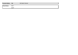
- 62. Function Button: Set Set Switch Channel Check Boxes: Ch. 1 Ch. P
- 63. Manual Switch (Freq. Div.) Manual switch/restore allows a channel to be switched to the protection channel. Function Button: Restore
- 64. Pull down Menu: Channel Number to Protect Alignment Switch Type No Lock Revert Limit Choose channel to protect. Alternatives: 1, P If "P" is selected means that the protected channel is reverted to its regular state unless the degradation is at or above the level defined by "No Lock Revert Limit" Alternatives: Aligned Checks that the signal from protection channel is aligned with the signal from the regular channel before the switch operation is performed. If no alignment is achieved within a certain period of time, the switch operation is aborted. Forced Performs an immediate switch operation (no alignment) Alternatives Nolock The switch operation will only be executed if no other channels are degraded to the level defined by "No Lock Revert Limit". If another channel's degradation reaches this level later, the manual operation is suspended and the channel is restored to its regular state. The manual request will be reactivated when no other channels are degraded to this level. Lock All automatic switch criteria is overridden by this manual request, and the manually switched channel will not be reverted by any event other than a manual restore request. Revert limit for a manually switched channel. Only applicable if "Switch Type" is Nolock. Alternatives: LOWRF, EW, LBER, HBER, OOS, RXINPUT
- 65. Switch Section Status (Freq. Div.) Displays the Switch Section status. Function Buttons: Get Start Polling Stop Polling Get Switch Section Status Start the polling function. The polling sequence will continu until Stop Polling is selected Stops Polling sequence
- 66. Switch Channel Status (Freq. Div.) Displays the Switch Channel status. Function Buttons: Get Start Polling Stop Polling Get Switch Channel Status Start the polling function. The polling sequence will continu until Stop Polling is selected Stops Polling sequence
- 67. Frequency Note! Setting of frequency requires connection to ODU. The Frequency page displays the frequency settings for all transceiver units in the same antenna direction. To change the frequencies: 1 Select a frequency plan from the combo box. "Manual Channel Setting" can also be selected as an option. 2 Select bandwidth from the combo box. 3 For each channel, select frequencies: 3.1 Select a Tx frequency from the combo box. The corresponding Rx channel will automatically be selected. Or; 3.2 Select an Rx frequency from the combo box. The corresponding Tx channel will automatically be selected. Note! If "Manual Channel Setting" is selected in step 1, the Tx and Rx frequencies have to be typed in manually. 4 Click the "Set" button to set the new frequencies
- 68. Function Buttons: Set Accept changes Pull-down menu settings Selected plan Bandwidth Tx (MHz) Rx (MHz) Select the correct Frequency plan Select the correct Bandwidth Select Transmit frequency Select Receive frequency
- 69. Backup The Backup page is divided in 3 sub-pages: Miscellaneous, Download and Replace SU. The Miscellaneous page contains the "Backup", "Restore" and "Upload" functions. The Download page contains the "Download" Function. The Replace SU page contains the "Replace SU Config Download" Function. Description: Backup Restore Upload Download Replace SU Makes a backup file of the SU configuration and stores this locally on the Network Element. Tip! It is recommended to take a backup when the system has been configured. Restores the SU configuration from a backup file stored locally on the Network Element Makes a backup file of the SU configuration and stores the file on your Personal computer or PC server. Downloads a backup file to the SU from your Personal computer or PC server. This function does the same operation as "Download". In addition a general time-limited license file is activated. This function is used if the SU is physically replaced. In this case a new license file must be installed before the preliminary licence file expires. Click on the page tabs to explore the individual functionality.
- 70. Miscellanous Function Buttons: Upload Backup Restore Upload the configuration from the NE to your local computer as a safety copy Make a backup file (locally on the NE) of the current configuration. Restore the configuration from a previously generated backup file
- 71. Download Function Buttons: Browse Download Browse your local computer for a configuration file to download to the NE Download the selected configuration file to the NE
- 72. Replace SU This function is used when a faulty SU is physically replaced by a new SU. The configuration must have been uploaded from the replaced SU, using the configuration upload feature under the Miscellaneous tab. The configuration from the replaced SU will be downloaded to the new SU. In addition the licenses from the replaced SU will be temporary enabled for a maximum period of 90 days in addition to any existing licenses on the new SU. These temporary licenses can be used while ordering new license keys from Nera.
- 73. Function Buttons: Browse Download Browse your local computer for a configuration file to download to the NE Downloads the selected configuration file to the NE and replaces the current NE configuration file
- 74. Software The Software page is divided in 2 sub-pages: SU SW Versions and SW Download. Click on the page tabs to explore the individual functionality.
- 75. SU Software Versions When new software is downloaded to the element it will initially be set in inactive state (Active no). Click the "Switch software" button to swap the Software Package. The system will perform a warm start when software is swapped.
- 76. Note! If only one software package is present on the Network Element, only one table will be visible in "Overview" in the screenshot above. Function Buttons: Switch Software Reset Software Swap between the two available software packages. Performs a warm reset of the NE software Note! Bit error may occur when software packages are switched. Note! It is recommended that you clear the file cache in your web browser after a software switch. The reason for this is to make sure that the browser receives the correct files. Complete state If all the required files are present and the checksum is OK, the software package is in Complete state. Compatible state Each software package contain a list of hardware compatibility requirements. This consists of a list of hardware modules with an accompanying version range. If all the detected modules in the system are found in this list, and their versions fall within the specified ranges, the software package is compatible.
- 77. Software Download A software release generally consists of several ".tar" files. When a new software version is downloaded to the NE, it is recommended to start with the ".tar" file with the lowest number (e.g. "SW-EVOULUTION-APP-R1A00_1.tar" and then "SW-EVOULUTION-APP-R1A00_2.tar" etc). Follow the instructions on the screen. If there is an inactive software package on the NE already, this software package will be overwritten. Dependent on the system configuration it is not always necessary to download all ".tar" files in the actual software release. After downloading the first file, you will be prompted for the next file to download, if required. When all required files are downloaded, the following message will be displayed: The software was downloaded successfully and is now in complete state. The downloaded software is still inactive. Activation of new software is performed from the "SU SW Versions" page. Function Buttons: Browse Download Browse your local computer for "Tar" files to download to the NE Downloads the selected "Tar" file and builds software hierarchy on the NE
- 78. Element The Element page is divided in 6 sub-pages: Licenses, Time and SNTP, SNMP, Web and Unconfigured Boards. Click on the page tabs to explore the individual functionality.
- 79. Licenses A traffic license may be required to enable traffic on the equipment. A Network Element can have several licenses installed, enabling different functions, such as transmission capacity, ethernet traffic and ethernet wayside traffic. For transmission capacities below 80 Mb/s, no license is required. The License Key is a 40 character alpha numeric string. Available license types: EVLIC-150M EVLIC-100M EVLIC-80M EVLIC-ETHERMAP EVLIC-METRO-XPIC 150 Mbit/s transmission capacity, per ODU 100 Mbit/s transmission capacity, per ODU 80 Mbit/s transmission capacity, per ODU Fast Ethernet traffic via SU port (currently only available in combination with EVLIC-150M license) XPIC license is required to enable XPIC filtering when two ODUs are operating in Co-channel Mode. One license pr. ODU pair.
- 80. Input field: License Key Type in the License Key Function Button: Apply Apply License Key
- 81. Time and SNTP A real-time clock is used by the NE to set timestamps on alarm and security events. This clock is also used for managing the collection and calculation of performance measurements. The system also provides SNTP functionality for syncronization of all clocks in the network. This function requires an SNTP server, either locally or on the internet (requires internet connection). This screenshot shows the Time and SNTP page with SNTP not selected.
- 82. Function Buttons: Time Status Get SNTP Configuration Set Manual time setting Set Synchronize with computer Get Time Status Click this button when the SNTP button has been unchecked, for returning to "Manual time setting" Set time Synchronizes the NE time setting with the local computer clock Check Box: SNTP enabled Open SNTP setup Pull down Menus: Manual Time Setting Date: yyyy-mm-dd Time: hh:mm:ss This screenshot shows the Time and SNTP page with SNTP selected.
- 83. Function Buttons: Time Status Get SNTP ConfigurationSet Get Time Status Setting of SNTP parameters Check Box: SNTP enabled Enables SNTP when the "Set" button is pushed. The SNTP IP address must be entered Input Field: SNTP Server's IP-address Input the IP address to the SNTP server Pull down Menus: Threshold-level for stratum alarm Poll Interval (seconds) The stratum level indicates the accuracy of the SNTP server clock. Highest accuracy is level 1. Alternatives: 1 to 15. Default value 2. Tip! If stratum alarm occurs frequently, the threshold-level should be set to lower accuracy (higher number). This will not influence the equipment performance. Determins the intervals between each clock update. Alternatives: 64 to 1024.
- 84. SNMP Simple Network Management Protocol (SNMP) is an application layer protocol that facilitates the exchange of management information between network devices. SNMP enables network administrators to manage network performance and find and solve network problems. SNMP is a simple request/response protocol. The network-management system issues a request, and managed devices return responses. Definitions Community Strings Private Public Assigns a password for read only queries Assigns a password for read/write queries SNMP Traps IP Address Trap Community String Trap Port The IP address to the SNMP server Either the Private or Public Community String Password The port number to send the SNMP trap to Function Buttons: Set Add Set Community Strings Add Trap
- 85. WEB
- 86. Function Button: Set Accept the changes Check Boxes: Global Polling Alarm Polling Housekeeping Polling System wide status poll. Enable/Disable background status polling for all web pages containing status information. You have the opportunity to override this setting. The overridden setting will only occur in the page where you override the settings and only last as long as the page is active. Default : OFF System wide alarm poll setting. Will display the highest alarm severity in the system, on the bottom of the page. Default: OFF System wide configuration polling. Will give notification if the system configuration has been changed. Default: OFF Note! Poll settings are not persistent across sessions, i.e. when the browser window is closed the poll settings will go back to their defaults.
- 87. Unconfigured Boards A list of any unconfigured boards and units.
- 88. Men At Work Function Button: RAISE/CLEAR Toggle "Men at Work" alarm in event log
- 89. Routing The Routing page is divided in 7 sub-pages: General Settings, Active Routes, Static Routes, Software, Element, Routing and Network. Click on the page tabs to explore the individual functionality.
- 90. General Settings The general settings page allows the user to control the general use of the OSPF and RIP 1 and 2 protocols for the NE. Enabling of protocols on specific interfaces are performed in the Rip Interfaces and OSPF Interfaces property pages. Function Button: Set Accept the changes
- 91. Check Boxes: OSPF Protocol RIP Protocol Enable Redistribute Enable Redistribute Rip Static OSPF Static Enable or disable the OSPF routing protocol Configuration of route redistribution from other protocols to OSPF as AS external routes. Enabling any of these will turn the router into an Autonomous System Border Router (ASBR) Controls redistribution of routes from RIP to OSPF. Controls redistribution of static routes to OSPF Enable or disable the RIP routing protocol. Configuration of route redistribution from other protocols to RIP. Controls redistribution of routes from OSPF to RIP. Controls redistribution of static routes to RIP. Input Fields: OSPF Protocol Default Cost RIP Protocol Default Metric Setting of default cost value used for OSPF protocol. The "Redistribute" options allow the OSPF protocol to pass the routing information of other routing protocols. For information to be passed between the OSPF and RIP protocols, the current NE must have both protocols enabled. Setting of default metric value used for RIP protocol. The "Redistribute" options allow the RIP protocol to pass the routing information of other routing protocols. For information to be passed between the OSPF and RIP protocols, the current NE must have both protocols enabled. List: IP Configurable Interfaces List of interfaces available on the current NE for the OSPF and RIP protocols (IP enabled interfaces) Interfaces may be enabled for IP in the Communication Ports page for the specific interface (e.g. NI interface on Metro).
- 92. Active Routes This is a list of currently active routes in the routing table. These are the routes that IP forwarding is based on. Inactive routes are not shown. Destination: Gateway: Subnet mask: Interface: Protocol: The destination of the route. The gateway of the route. The subnet mask of the route. The name of the interface associated with this route. The protocol that this route was learnt from.
- 93. Static Routes Edit static routes regarding IP Routing using this page.
- 94. Function Button: Add Delete Set Cancel Add a static route Delete selected static route Apply the setting Discard changes Pull Down Menus: Interface Metric Gateway interface if specified. Default “Any” interface The route metric. Possible values: 0-15 Input Fields: Destination Gateway Subnet mask Route destination in “x.x.x.x” notation Note! The IP address must be valid for the given subnet mask. Route gateway in “x.x.x.x” notation if needed. Note! Gateway must be present if interface is set to “Any”. Route subnet mask in “x.x.x.x” notation Note! The subnet mask must be continuous.
- 95. RIP Interfaces This configures which interfaces to run RIP on and the parameters used for each interface. Note! In order to edit the "RIP areas" settings, the RIP protocol must be disabled in the General Settings page.
- 96. Function Button: Add Edit Delete Set Cancel Add an Interface to run RIP on Change configuration for an interface running RIP Remove RIP configuration form an interface Apply the setting Discard changes Pull Down Menus: Interface Metric RIP Version The name of the interface being configured. Select between the alternatives: Io#, eth#, DIR0@# The metric associated with the interface. Possible values: 0-16 The version of RIP to run on an interface. (RIP v. 1 or RIP v. 2). Alternatives: 1, 2 Note! When running RIP v.1 on an interface, limitations in the RIP v.1 protocol will restrict which routes may be announced through this interface
- 97. OSPF Interfaces This configures which interfaces to run OSPF on and the parameters used for each interface. Note! In order to edit the ‘OSPF areas’ settings, the OSPF protocol must be disabled in the General Settings page.
- 98. Function Button: Add Edit Delete Set Cancel Add an Interface to run OSPF on Change configuration for an interface running OSPF Remove OSFP configuration form an interface Apply the setting Discard changes Pull Down Menus: Interface Id Area The name of the interface being configured. Select between the alternatives: Io#, eth#, DIR0@# The ID of the area associated with this interface Input Fields: Cost Transmit delay Designated Router Priority Retransmit Interval The associated cost of this interface The estimated transmit delay through this interface in seconds - Default value is 1 second. - Possible values: 1 - 65535. Indicates the current NE’s reliability as a designated router (DR). Higher values = higher reliability. - 0 = cannot be DR. - Possible values: 0 - 255. Hello Interval Router Dead Interval The interval between OSPF hello packets on this interface. The time before declaring a link down in the absence of hello packets
- 99. OSPF Areas This configures OSPF areas for this router. Note! In order to edit the ‘OSPF areas’ settings, the OSPF protocol must be disabled in the General Settings page.
- 100. Function Buttons OSPF Areas: Networks Add/Edit OSPF area Add Edit Delete Add Set Cancel Add an OSPF area Change configuration for an OSPF area Remove OSFP area configuration Add Network Apply the setting Discard changes Input Fields: Area Id Stub Area Default Cost The ID of the area. Either in “x.x.x.x” notation or plain number Configures this area as “stub area” Sets the default cost for this area. Possible values: 0-65535
- 101. Virtual Links This configures OSPF virtual links for this router.
- 102. Function Buttons: Add Edit Delete Set Cancel Add a OSPF virtual link Change configuration for an OSPF virtual link Remove OSFP virtual link configuration Apply the setting Discard changes Pull Down Menus: Transit area State The ID of the area to use as transit area for the link Not in use Input Field: Router Id The ID of the backbone router on the other end of the link
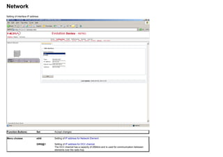
- 103. Network Setting of Interface IP address Function Buttons: Set Accept changes Menu choises eth0 Setting of IP address for Network Element DIR0@1 Setting of IP address for DCC channel. The DCC channel has a capacity of 256kb/s and is used for communication betwwen elements over the radio hop.
- 104. OH Channels This page gives an overview of the OverHead Connection status. Both SOH/TOH bytes (METRO) and NOH channels are listed. Function Button: Apply Filter Filter list according to selections. Pull Down Menus Physical Position Physical position of the unit where the performance measurements are performed Logical Position Overhead Localisation of the unit w.r.t traffic direction SOH bytes (ETSI)/TOH bytes (ANSI) or NOH channels
- 105. Mother Board Set up and configuration of the Mother Board. Click on the different sub pages for more information. The configuration options for the Mother Board are dependent on the system configuration, i.e. METRO and XPAND configuration pages will have different sub-menus. If Configuration, Fault or Performance are selected from the Menu bar, with the Mother Board highlighted, the Configuration, Fault or Performance data for the Mother Board are displayed. METRO
- 106. XPAND
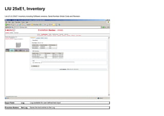
- 107. Mother Board METRO, Inventory List of Mother Board Inventory including Software versions, Serial Number Article Code and Revision. Input Field: Log Log available for user defined text input Function Button: Set Log Saves the text entries to the Log
- 108. Mother Board METRO, Path Trace The Path Trace functionality and the AIS (Alarm Indicator Signal) functionality are used to test that the received STM-1 frames are the frames we want to receive (correct routing, frequency alignment. . . . ). This is done by either inserting a fixed byte or a user defined ASCII string in the J0 slot in the RSOH (Send). The radio that receives the STM-1 frames must have the same Trace string (J0) defined. If there is a mismatch, an AIS can be inserted. An AIS can also be inserted if the HBER threshold is exceeded.
- 109. Check Boxes: Enable send Enable receive Enable send Trace string Enable Receive Trace string Function Buttons: Set (Send) Set (Receive) Get Start Polling Stop Polling Set Path Trace signal to send Set Path Trace signal expected to receive Get Status Start polling Status Stop polling Status Input Fields: Send Trace string Receive Expected User defined ASCII string max. 15 characters User defined ASCII string max. 15 characters
- 110. Mother Board METRO, AIS The Path Trace functionality and the AIS (Alarm Indicator Signal) functionality are used to verify that the received STM-1 frames are the frames we want to receive (correct routing, frequency alignment. . . . ). This is done by either inserting a fixed byte or a user defined ASCII string in the J0 slot in the RSOH. This is done from the Path Trace sheet. The radio that receives the STM-1 frames must have the same Trace string (J0). If there is a mismatch, an AIS can be inserted. An AIS can also be inserted if the HBER threshold is exceeded.
- 111. Check Boxes: Insert AIS on Trace Identifier Mismatch (TIM) Remove Delay Enabled When this box is checked, an Alarm Indicating Signal is inserted when there is a mismatch between the Path Trace string or fixed byte sent and the expected Receive signal Remove AIS delay Pull Down Menu: AIS remove delay (in sec) Setting of AIS remove dela: 0-300 seconds Function Button: Set Set AIS parameters
- 112. Mother Board METRO, Analogues This page gives the status of the IFU Basic Frame voltage levels.
- 113. Mother Board METRO, IFUTest By clicking the TEST buttons on the screenshot below, direct access to the Looping /PRBS pages on the LIU and RIU units is available. By clicking the corresponding "looping arrows", loops can be set for testing purposes. Pull Down Menus: Time Out Value Setting of Time Out Value for IFU Test
- 114. Function Button: Arrow TEST Setting of loop Link to Looping /PRBS pages on the LIU and RIU units LIU Looping
- 115. LIU PRBS
- 116. RIU Looping
- 117. Mother Board XPAND, Inventory List of Mother Board Inventory including Software versions, Serial Number Article Code and Revision. Input Field: Log Log available for user defined text input Function Button: Set Log Saves the text entries to the Log
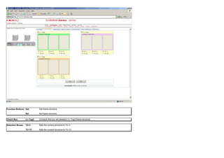
- 118. Mother Board XPAND, IFU Test By clicking the TEST buttons on the screenshot below, direct access to the Looping /PRBS pages on the "E1/T1" and RIU units is available. By clicking the corresponding "looping arrows", loops can be set for testing purposes. Pull Down Menus: Time Out Value Setting of Time Out Value for IFU Test
- 119. Function Button: Arrow TEST Setting of loop Link to Looping /PRBS pages on the "E1/T1" and RIU units LIU 25XE1 Looping
- 120. LIU 25XE1 PRBS
- 121. RIU Looping
- 122. Mother Board XPAND, Cross-Connect The Motherboard has a built-in cross connect with 4 ports. The Cross-connect allows the operator to interconnect traffic on these ports. The connections are identified by using the background colour of the ports together with the address of the virtual container. The background colour of a virtual container identifies the source port, while the address identifies the source address. SNCP functionality is identified with a split cell. When configuring the cross-connection of virtual containers, three modes are available, cross-connection of two channels, cross-connection with SNCP (Path protection) and cross connection of Ethernet. SNCP can be activated for each individual virtual container separately. 1. Cross-connection without SNCP: Select the source virtual container by clicking inside the square for that container. A range of virtual containers can be selected by click and drag. Push the Connect button and then select the sink virtual container by clicking inside the square for that container. Verify the correct cross-connection before pushing the Set button to apply the setting to the Unit. Disconnecting of a connection is done by selecting either of the two virtual containers in a connection and push the Disconnect button and the Set button. 2. Cross-connection with SNCP: Select the Sink virtual container(s) for the SNCP connection. Click the SNCP Connect button. Select the first source virtual container by clicking inside square for that container. Then select the second source virtual container by clicking inside the square for that container. Press the Connect button. Verify the correct SNCP cross-connection before pushing the Set button, to apply the setting to the Unit. Disconnecting of a connection is done selecting any of the three virtual containers in a connection and push Disconnect button and Set button. 3. Cross-connection Ethernet: Select the source virtual container by clicking inside the square for that container. A range of virtual containers can be selected by clicking the first and then the last virtual container in the range. Click the Connect Ethernet button and then click on any virtual container in the target RIU. The SU Ethernet virtual containers will occupy the virtual containers with the highest address numbers in the RIU. It is therefore important that these virtual containers are free before attempting to connect Ethernet. Verify the correct cross-connection before pushing the Set button to apply the setting to the Unit. Disconnecting of the Ethernet connection is done by pushing "Disconnect Ethernet" button and Set button. Note: The configuration is not applied to the unit before the Set button is pushed. Several cross-connections and SNCP connections can be configured before the Set button is pushed.
- 124. Function Button: Connect SNCP Connect Disconnect Connect Ethernet Disconnect Ethernet Loop Disconnect Loop Get Set Select the channels to be connected. Press this button. Then select the target channel. Select the Sink Channel(s). Press this button. Select the first SNCP channel. Then select the second SNCP Channel. Select a channel which already has an established connection. Press this button to remove the connection. Select a range of Ethernet channels. Push this button. Click on any channel in the target RIU. Push this button to disconnect the Ethernet connection. Click on the channel to be looped. Press this button to activate the loop. Click on the active loop to be disconnected. Push this button to disconnect the loop. Get status Apply the selected connections
- 125. Mother Board XPAND, Cross-Connect Status Overview of IFU XPAND Cross-Connect Status. Gray coloured virtual containers: signal ok Yellow coloured virtual containers: Payload mismatch Red coloured virtual containers: Alarm
- 126. Function Button: Get Start Polling Stop Polling Get Cross-Connect status Start polling of Cross-Connect status Stop polling of Cross-Connect status
- 127. Mother Board XPAND, SNCP Status The SNCP status is indicated by using the background colour of the active port. In the example below, the active source comes from the violet port: /ne/frame-1/slot-3/E1. Function Button: Get Get SNCP status Start Polling Stop Polling Start polling of SNCP status Stop polling of SNCP status
- 128. Auxiliary Units Available AUX Units: Engineering Orderwire Unit (EOW) 4x64kb/s Unit Alarm & Control Unit (ACU) E1/T1 Wayside Unit
- 129. Engineering Orderwire Unit (EOW) Set up and configuration of the EOW Unit. Click on the different sub page tabs for more information. If Configuration, Fault or Performance are selected from the Menu bar, with the EOW Unit highlighted, the Configuration, Fault or Performance data for the EOW Unit are displayed.
- 130. EOW, Inventory List of EOW Inventory including Software versions, Serial Number Article Code and Revision.
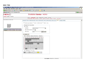
- 131. EOW Engineering Order Wire can be inserted in dedicated SOH (ETSI) / TOH (ANSI) bytes, or the NOH (Nera Overhead) channels. The NOH channels are not available when Direction: Line (Traffic over Line Interface Unit) is selected. The check box "Enable" must be checked for setup of EOW connections. When SOH / TOH button is pushed, an SOH / TOH matrix is displayed. Available SOH / TOH bytes (white colour) can be selected. The Byte will turn yellow indicating that the byte is selected for EOW traffic. If the NOH button is pushed, NOH channel 1 or 2 can be selected. The Service Telephone connector is inserted in Port1 on the EOW Unit.
- 132. SOH / TOH
- 133. Pull Down Menus: Direction Main Traffic Channel Selection of EOW traffic direction. Alternatives: Line or Antenna Direction (The name for the Antenna Direction that was entered under Unit Housekeeping will appear in the Pull Down Menu) Selection of Main Traffic Channel. Dependent on the number of Regular Channels NOH
- 134. Function Buttons SOH / TOH NOH Set Selection of available Section Overhead / Traffic Overhead byte Selection of Nera Overhead Channel. Alternatives: Channel 1 or Channel 2 Setting of EOW parameters Check Boxes: Enable (NOH) Channel 1 (NOH) Channel 2 Enabling of EOW Connection Selection of EOW traffic on NOH channel 1 Selection of EOW traffic on NOH channel 2 Input Field: Number Setting of Telephone number. Alternatives: 00 to 99
- 135. EOW, Analog Ports Other Equipment 1 & 2: These two balanced interfaces are meant for interconnection between similar equipment. A maximum of 3 Service Telephone Units can be connected this way. These interfaces are not over-voltage protected and not galvanic isolated and are therefore not recommended for long lines or outdoor use. - Port input level (dBm): Not adjustable. Nominal value: -6.0 dBm. - Port output level (dBm): Not adjustable. Nominal value -6.0dBm. 4 Wire interface: This is a balanced, galvanic isolated interface meant to interface various types of equipment. Input- and output- gain can be adjusted over a wide range. - Port input level (dBm): Adjustable range: 4dBm to -10.0dBm. - Port output level (dBm): Adjustable range: 4dBm to -10.0dBm.
- 136. Pull Down Menus: Remote (4 Wire) Port input level Remote (4 Wire) Port output level Adjustable range: 4dBm to -10.0dBm. Adjustable range: 4dBm to -10.0dBm. Function Button Set Setting of Analog Ports parameters Check Boxes: Enable analog port Transit other equipment 1 to other equipment 2 Enabling of the analog ports. If the check box is unchecked, the analog ports are disabled. By checking this box, the signal is through conncted between Port 2 and Port 3 on the EOW Unit.
- 137. EOW, G.703 on Port 2 G.703 can be inserted in dedicated SOH (ETSI) / TOH (ANSI) bytes, or the NOH (Nera Overhead) channels. The NOH channels are not available when Direction: Line (Traffic over Line Interface Unit) is selected. The check box "Enable" must be checked for setup of G.703 connections. When SOH / TOH button is pushed, an SOH / TOH matrix is displayed. Available SOH / TOH bytes (white colour) can be selected. The Byte will turn yellow indicating that the byte is selected for G.703 traffic. If the NOH button is pushed, NOH channel 1 or 2 can be selected.
- 138. SOH / TOH
- 139. Pull Down Menus: Direction Main Traffic Channel Selection of G.703 traffic direction. Alternatives: Line or Antenna Direction (The name for the Antenna Direction that was entered under Unit Housekeeping will appear in the Pull Down Menu) Selection of Main Traffic Channel. Dependent on the number of Regular Channels NOH
- 140. Function Buttons SOH / TOH NOH Set Selection of available Section Overhead / Traffic Overhead byte Selection of Nera Overhead Channel. Alternatives: Channel 1 or Channel 2 Setting of G.703 parameters Check Boxes: Enable (NOH) Channel 1 (NOH) Channel 2 Enabling of G.703 Connection Selection of G.703 traffic on NOH channel 1 Selection of G.703 traffic on NOH channel 2
- 141. EOW, G.703 on Port 3 G.703 can be inserted in dedicated SOH (ETSI) / TOH (ANSI) bytes, or the NOH (Nera Overhead) channels. The NOH channels are not available when Direction: Line (Traffic over Line Interface Unit) is selected. The check box "Enable" must be checked for setup of G.703 connections. When SOH / TOH button is pushed, an SOH / TOH matrix is displayed. Available SOH / TOH bytes (white colour) can be selected. The Byte will turn yellow indicating that the byte is selected for G.703 traffic. If the NOH button is pushed, NOH channel 1 or 2 can be selected.
- 142. SOH / TOH
- 143. Pull Down Menus: Direction Main Traffic Channel Selection of G.703 traffic direction. Alternatives: Line or Antenna Direction (The name for the Antenna Direction that was entered under Unit Housekeeping will appear in the Pull Down Menu) Selection of Main Traffic Channel. Dependent on the number of Regular Channels Function Buttons SOH / TOH NOH Set Selection of available Section Overhead / Traffic Overhead byte Selection of Nera Overhead Channel. Alternatives: Channel 1 or Channel 2 Setting of G.703 parameters NOH
- 144. Check Boxes: Enable (NOH) Channel 1 (NOH) Channel 2 Enabling of G.703 Connection Selection of G.703 traffic on NOH channel 1 Selection of G.703 traffic on NOH channel 2
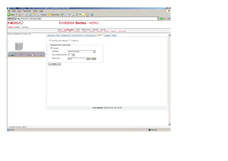
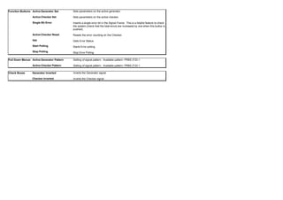
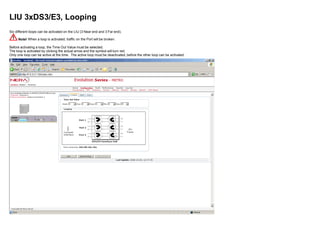
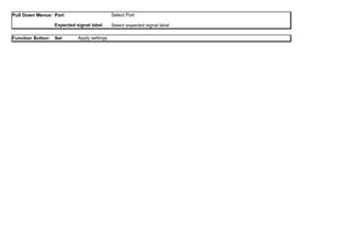
- 145. EOW, HDLC 1 (High-Level Data Link Control) EOW HDLC communication utilities: 64kb/s user channel Enables a 64kb/s communication channel between the IFUs Supervisor Unit's software and a remote site SU, enabling remote management and configuration/control. To utilize this operation the HDLC device has to be assigned an IP address and included in the Supervisor software's IP routing table on both ends of this communication channel, plus directed into a SOH or NOH channel towards a particular antenna direction. The IP-address assignment is done in the configuration-->network menu. This remote management and configuration/control function is accessable through, as usual, a web-browser and the remote WEB management and configuration service. The check box "Enable" must be checked for setup of 64kb/s connections. When SOH / TOH button is pushed, an SOH / TOH matrix is displayed. Available SOH / TOH bytes (white colour) can be selected. The byte will turn yellow indicating that the byte is selected for 64kb/s traffic. If the NOH button is pushed, NOH channel 1 or 2 can be selected. G.703 Co-directional The check box "Enable" must be checked for setup of G.703 Co-directional connections. Enables the HDLC device to send data between Port 3 and the SU, which provide two different functions Terminal-server function This function provide access to Port 3 from a telnet-connection on the Supervisory Unit. Ex. connect a PC to the SU and start the telnet application on the PC and connect to the targets IP address and TCP port #. This will then provide some simple means to access and control other devices and units. The TCP port # is assigned according to the following parameters: First digit - 3 Second digit - Equal to the IFU number Third digit - Equal to slot number -7. E.g. Upper left most slot (slot # 7) gives the digit; 7-7=0 Fourth digit - 0 Local Management connection This is similar to the remote management connection, but the "remote" unit to manage is in the near vicinity - usually in the same room. E.g. Web-client <--> PC <--> IFU#1[SU <--> EOW <--> HDLC <---> Port#3] <----- Cross con cable -----> IFU#2 [Port#3 <--> HDLC <---> EOW <--> SU <--> WEB-Service <--> configuration software <--> IFU Hardware]
- 147. SOH / TOH
- 148. NOH
- 149. Pull Down Menus: Direction Main Traffic Channel Selection of traffic direction. Options: Line or Antenna Direction (The name for the Antenna Direction that was entered under Unit Housekeeping will appear in the Pull Down Menu) Selection of Main Traffic Channel. Dependent on the number of Regular Channels G.703 Co-directional
- 150. Function Buttons SOH / TOH NOH Set Selection of available Section Overhead / Traffic Overhead byte Selection of Nera Overhead Channel. Alternatives: Channel 1 or Channel 2 Setting of new parameters Check Boxes: Enable (NOH) Channel 1 (NOH) Channel 2 Enabling of HDLC Connection Selection of traffic on NOH channel 1 Selection of traffic on NOH channel 2
- 151. EOW, Looping Four different loops can be activated on the EOW Unit. One near end loop at each customer interface, G.703 (Port 2 and 3) and one corresponding far end loop. Note! When a loop is activated, traffic on the EOW Port will be broken. Before activating a loop, the Time Out Value must be selected. The loop is activated by clicking the actual arrow and the symbol will turn red. Only one loop can be active at the time. The active loop must be deactivated, before the other loop can be activated.
- 152. Function Buttons: Get Start Polling Stop Polling Get Loop Status Start Loop Status Polling Stop Loop Status Polling Pull Down Menus: Time Out Value Setting of loop Time Out values; Week, Day, Hour, Min, Sec
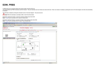
- 153. EOW, PRBS A PRBS signal can be inserted instead of the regular traffic to test the EOW Unit. The EOW contains two PRBS Generators and two Checkers. Only one Generator and one Checker are active at the time. When one checker is enabled, by clicking the arrow on the block diagram, the other will automatically be disabled. The Generator is started by clicking the Generator arrow on the block diagram. The arrow turns red. Note! When the Generator is activated, traffic on this Port will be broken. Activate the uppermost Checker, to test the Customer Interface side of the EOW. Note! A loop must be activated at the Customer interface side. Activate the rightmost Checker, to test the IFU Basic Frame interface side of the EOW. Note! A loop must be activated at the IFU Basic Frame interface side.
- 154. Function Buttons: Active Generator Set Active Checker Set Single Bit Error Active Checker Reset Get Start Polling Stop Polling Sets parameters on the active generator. Sets parameters on the active checker. Inserts a single error bit in the Signal Frame. This is a helpful feature to check the system (check that the total errors are increased by one when this button is pushed). Resets the error counting on the Checker. Gets Error Status Starts Error polling Stop Error Polling Pull Down Menus: Active Generator Pattern Active Checker Pattern Setting of signal pattern. Available pattern: PRBS 2*23-1 Setting of signal pattern. Available pattern: PRBS 2*23-1 Check Boxes Generator Inverted Checker Inverted Inverts the Generator signal Inverts the Checker signal
- 155. 4x64kb/s Unit Set up and configuration of the 64kb/s Unit. Click on the different sub page tabs for more information. If Configuration, Fault or Performance are selected from the Menu bar, with the 64kb/s Unit highlighted, the Configuration, Fault or Performance data for the 64kb/s Unit are displayed.
- 156. 4x64kb/s Unit, Inventory List of 4x64kb/s Unit Inventory including Software versions, Serial Number Article Code and Revision.
- 157. 4x64kb/s Unit, Port 1 - G.703 Contra Directional G.703 can be inserted in dedicated SOH (ETSI) / TOH (ANSI) bytes, or the NOH (Nera Overhead) channels. The check box "Enable" must be checked for setup of G.703 connections. When SOH / TOH button is pushed, an SOH / TOH matrix is displayed. Available SOH / TOH bytes (white colour) can be selected. The Byte will turn yellow indicating that the byte is selected for G.703 traffic. If the NOH button is pushed, NOH channel 1 or 2 can be selected.
- 158. SOH / TOH
- 159. NOH
- 160. Pull Down Menus: Direction Main Traffic Channel Selection of G.703 traffic direction. Alternatives: Line or Antenna Direction (The name for the Antenna Direction that was entered under Unit Housekeeping will appear in the Pull Down Menu) Selection of Main Traffic Channel. Dependent on the number of Regular Channels Function Buttons SOH / TOH NOH Set Selection of available Section Overhead / Traffic Overhead byte Selection of Nera Overhead Channel. Alternatives: Channel 1 or Channel 2 Setting of G.703 parameters Check Boxes: Enable (NOH) Channel 1 (NOH) Channel 2 Enabling of G.703 Connection Selection of G.703 traffic on NOH channel 1 Selection of G.703 traffic on NOH channel 2
- 161. 4x64kb/s Unit, Port 2 - G.703 Co-Directional G.703 can be inserted in dedicated SOH (ETSI) / TOH (ANSI) bytes, or the NOH (Nera Overhead) channels. The check box "Enable" must be checked for setup of G.703 connections. When SOH / TOH button is pushed, an SOH / TOH matrix is displayed. Available SOH / TOH bytes (white colour) can be selected. The Byte will turn yellow indicating that the byte is selected for G.703 traffic. If the NOH button is pushed, NOH channel 1 or 2 can be selected.
- 162. SOH / TOH
- 163. NOH
- 164. Pull Down Menus: Direction Main Traffic Channel Selection of G.703 traffic direction. Alternatives: Line or Antenna Direction (The name for the Antenna Direction that was entered under Unit Housekeeping will appear in the Pull Down Menu) Selection of Main Traffic Channel. Dependent on the number of Regular Channels Function Buttons SOH / TOH NOH Set Selection of available Section Overhead / Traffic Overhead byte Selection of Nera Overhead Channel. Alternatives: Channel 1 or Channel 2 Setting of G.703 parameters Check Boxes: Enable (NOH) Channel 1 (NOH) Channel 2 Enabling of G.703 Connection Selection of G.703 traffic on NOH channel 1 Selection of G.703 traffic on NOH channel 2
- 165. 4x64kb/s Unit, Port 3 - G.703 Co-Directional G.703 can be inserted in dedicated SOH (ETSI) / TOH (ANSI) bytes, or the NOH (Nera Overhead) channels. The check box "Enable" must be checked for setup of G.703 connections. When SOH / TOH button is pushed, an SOH / TOH matrix is displayed. Available SOH / TOH bytes (white colour) can be selected. The Byte will turn yellow indicating that the byte is selected for G.703 traffic. If the NOH button is pushed, NOH channel 1 or 2 can be selected.
- 166. SOH / TOH
- 167. NOH
- 168. Pull Down Menus: Direction Main Traffic Channel Selection of G.703 traffic direction. Alternatives: Line or Antenna Direction (The name for the Antenna Direction that was entered under Unit Housekeeping will appear in the Pull Down Menu) Selection of Main Traffic Channel. Dependent on the number of Regular Channels Function Buttons SOH / TOH NOH Set Selection of available Section Overhead / Traffic Overhead byte Selection of Nera Overhead Channel. Alternatives: Channel 1 or Channel 2 Setting of G.703 parameters Check Boxes: Enable (NOH) Channel 1 (NOH) Channel 2 Enabling of G.703 Connection Selection of G.703 traffic on NOH channel 1 Selection of G.703 traffic on NOH channel 2
- 169. 4x64kb/s Unit, Port 4 - V.11 V.11 can be inserted in dedicated SOH (ETSI) / TOH (ANSI) bytes, or the NOH (Nera Overhead) channels. The check box "Enable" must be checked for setup of V.11 connections. When SOH / TOH button is pushed, an SOH / TOH matrix is displayed. Available SOH / TOH bytes (white colour) can be selected. The Byte will turn yellow indicating that the byte is selected for V.11 traffic. If the NOH button is pushed, NOH channel 1 or 2 can be selected.
- 170. SOH / TOH
- 171. NOH
- 172. Pull Down Menus: Direction Main Traffic Channel Selection of V.11 traffic direction. Alternatives: Line or Antenna Direction (The name for the Antenna Direction that was entered under Unit Housekeeping will appear in the Pull Down Menu) Selection of Main Traffic Channel. Dependent on the number of Regular Channels Function Buttons SOH / TOH NOH Set Selection of available Section Overhead / Traffic Overhead byte Selection of Nera Overhead Channel. Alternatives: Channel 1 or Channel 2 Setting of V.11 parameters Check Boxes: Enable (NOH) Channel 1 (NOH) Channel 2 Enabling of V.11 Connection Selection of V.11 traffic on NOH channel 1 Selection of V.11 traffic on NOH channel 2
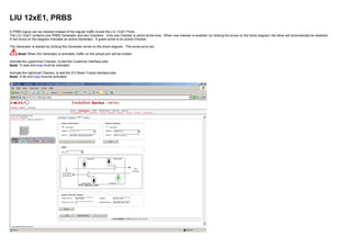
- 173. 4x64kb/s Unit, HDLC (High-Level Data Link Control) 64kb/s HDLC communication utilities: 64kb/s user channel Enables a 64kb/s communication channel between the IFUs Supervisor Unit's software and a remote site SU, enabling remote management and configuration/control. To utilize this operation the HDLC device has to be assigned an IP address and included in the Supervisor software's IP routing table on both ends of this communication channel, plus directed into a SOH or NOH channel towards a particular antenna direction. The IP-address assignment is done in the configuration-->network menu. This remote management and configuration/control function is accessable through, as usual, a web-browser and the remote WEB management and configuration service. The check box "Enable" must be checked for setup of 64kb/s connections. When SOH / TOH button is pushed, an SOH / TOH matrix is displayed. Available SOH / TOH bytes (white colour) can be selected. The byte will turn yellow indicating that the byte is selected for 64kb/s traffic. If the NOH button is pushed, NOH channel 1 or 2 can be selected. G.703 Co-directional The check box "Enable" must be checked for setup of G.703 Co-directional connections. Enables the HDLC device to send data between Port 3 and the SU, which provide two different functions Terminal-server function This function provide access to Port 3 from a telnet-connection on the Supervisory Unit. Ex. connect a PC to the SU and start the telnet application on the PC and connect to the targets IP address and TCP port #. This will then provide some simple means to access and control other devices and units. The TCP port # is assigned according to the following parameters: First digit - 3 Second digit - Equal to the IFU number Third digit - Equal to slot number -7. E.g. Upper left most slot (slot # 7) gives the digit; 7-7=0 Fourth digit - 0 Local Management connection This is similar to the remote management connection, but the "remote" unit to manage is in the near vicinity - usually in the same room. E.g.
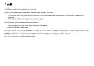
- 174. Web-client <--> PC <--> IFU#1[SU <--> EOW <--> HDLC <---> Port#3] <----- Cross con cable -----> IFU#2 [Port#3 <--> HDLC <---> EOW <--> SU <--> WEB-Service <--> configuration software <--> IFU Hardware] Port 4 - V.11 The check box "Enable" must be checked for setup of V.11 connections. Enables the HDLC device to send data between Port 4 and the SU, which provide two different functions; Terminal-server function and Local Management connection. See G.703 Co-directional description.
- 175. SOH / TOH
- 176. NOH
- 177. G.703 Co-directional
- 178. V.11 Pull Down Menus: Clock Baud Rate Options: Contra Master, Co-dir or Slave Options: 64kb/s or 256kb/s
- 179. Pull Down Menus: Direction Main Traffic Channel Selection of traffic direction. Alternatives: Line or Antenna Direction (The name for the Antenna Direction that was entered under Unit Housekeeping will appear in the Pull Down Menu) Selection of Main Traffic Channel. Dependent on the number of Regular Channels Function Buttons SOH / TOH NOH Set Selection of available Section Overhead / Traffic Overhead byte Selection of Nera Overhead Channel. Alternatives: Channel 1 or Channel 2 Setting of new parameters Check Boxes: Enable (NOH) Channel 1 (NOH) Channel 2 Enabling of HDLC Connection Selection of traffic on NOH channel 1 Selection of traffic on NOH channel 2
- 180. 4x64kb/s Unit, Looping Eight different loops can be activated on the 4x64kb/s Unit. One near end loop for (Port 1 - 4) and one corresponding far end loop. Note! When a loop is activated, traffic on the 64kb/s Port will be broken. Before activating a loop, the Time Out Value must be selected. The loop is activated by clicking the actual arrow and the symbol will turn red. Only one loop can be active at the time. The active loop must be deactivated, before the other loop can be activated.
- 181. Function Buttons: Get Start Polling Stop Polling Get Loop Status Start Loop Status Polling Stop Loop Status Polling Pull Down Menus: Time Out Value Setting of loop Time Out values; Week, Day, Hour, Min, Sec
- 182. 4x64kb/s Unit, PRBS A PRBS signal can be inserted instead of the regular traffic to test the 4x64kb/s Unit. The 4x64kb/s Unit contains two PRBS Generators and two Checkers. Only one Generator and one Checker are active at the time. When one checker is enabled, by clicking the arrow on the block diagram, the other will automatically be disabled. The Generator is started by clicking the Generator arrow on the block diagram. The arrow turns red. Note! When the Generator is activated, traffic on this Port will be broken. Activate the uppermost Checker, to test the Customer Interface side of the 4x64kb/s Unit. Note! A loop must be activated at the Customer interface side. Activate the rightmost Checker, to test the IFU Basic Frame interface side of the 4x64kb/s Unit. Note! A loop must be activated at the IFU Basic Frame interface side.
- 183. Function Buttons: Active Generator Set Active Checker Set Single Bit Error Active Checker Reset Get Start Polling Stop Polling Sets parameters on the active generator. Sets parameters on the active checker. Inserts a single error bit in the Signal Frame. This is a helpful feature to check the system (check that the total errors are increased by one when this button is pushed). Resets the error counting on the Checker. Gets Error Status Starts Error polling. Stop Error Polling Pull Down Menus: Active Generator Pattern Active Checker Pattern Setting of signal pattern. Available pattern: PRBS 2*23-1 Setting of signal pattern. Available pattern: PRBS 2*23-1 Check Boxes Generator Inverted Checker Inverted Inverts the Generator signal Inverts the Checker signal
- 184. Alarm & Control Unit (ACU) Set up and configuration of the ACU Unit. Click on the different sub page tabs for more information. The ACU enables supervisory of external equipment. The ACU unit enables access of external analogue inputs (7) and external alarm inputs (8) and generation of alarm/relay outputs (4). The “Relay Config”, “Alarm Input”, “Alarm Output” and “Analogue Config” are ACU specific configuration menus. The “Inventory” and “Analogue” menus display current information. The “Relay Control” enables customer to operate relay outputs. If Configuration, Fault or Performance are selected from the Menu bar, with the ACU Unit highlighted, the Configuration, Fault or Performance data for the ACU Unit are displayed.
- 185. ACU, Inventory List of ACU Inventory including Software versions, Serial Number Article Code and Revision.
- 186. ACU, Alarm Input Configuration menu for input alarm signals. The ACU is equipped with 8 current loop connections alarm inputs each equipped with positive- and negative- input pins. The input alarms are enrolled into the supervisory system. The ACU detects a change of input state when the following conditions are satisfied: Interface current loop, state on: > 3.0 mA Interface current loop, state off: < 1.0 mA Transient protection, amplitude: < 100 V Transient protection, duration: < 10 ms, non-repetitive Input Alarm State configuration: The supervisory system allows the operator to set alarm state, HIGH / LOW. Input Alarm Name configuration: Unique names can be configured to the input alarms.
- 187. Function Button: Set Set selected parameters Pull Down Menus: Auxiliary Alarm Input Active (1-8) Alternatives: High Low
- 188. ACU, Relay Control The “Relay Control” menu can operate “Latched” and “Pulsed” relay outputs. The ACU is equipped with 4 relay outputs which can be configured to Latched-, Pulsed- or Alarm Output- mode. The Alarm Output relays are controlled by the supervisory system while the Latched- and Pulsed- relays can be operated manually. Latched relays: The operator can switch the output state from OPEN to CLOSED or from CLOSED to OPEN. Pulse relays: The operator can generate a pulse of a predefined length specified in the ACU, Relay Config. Description of parameters: ID: Refer to physical relay (hardware) Name: Given relay name, ref. ACU, Relay Config Mode: Configured relay mode: Latched-, Pulsed- or Alarm Out- type Pulse: Parameter valid only for Pulsed type relays Status: Detected status Note! Relay status is be updated when an action is performed. Action: Manual operation valid only for Latched- and Pulsed- type relays.
- 189. ACU, Relay Config The ACU is equipped with 4 relay output which can be setup as Latched-, Pulsed- or Alarm Out- type relays. Latched Mode - Configuration parameters: ID: Refer to physical relay (hardware) Name: Changeable relay name referred to by the supervisory system. Mode: Latched Pulse (in 0.5s): Not Applicable Active State: Not Applicable Pulsed Mode - Configuration parameters: ID: Refer to physical relay (hardware) Name: Changeable relay name referred to by the supervisory system. Mode: Pulsed Pulse (in 0.5s): Configurable pulse length selected from the range of 0.5s to 62.5s Active State: Configurable pulse state, OPEN / CLOSED Alarm Out Mode - Configuration parameters: ID: Refer to physical relay (hardware) Name: Changeable relay name referred to by the supervisory system. Mode: Alarm Out Pulse (in 0.5s): Not Applicable Active State: Configurable Alarm Out state, OPEN / CLOSED
- 190. ACU, Alarm Output The ACU, Alarm Output menu enables the operator to select one or more available alarms and output their contribution onto the Alarm Out. The Alarm Out state is configured in the ACU, Relay Config menu. The left window displays a tree with all available alarms which can be selected and connected to the selected Alarm Out on the right window.
- 191. ACU, Analogue Config The ACU, Analogue Config menu enables analogue input readings and by setting parameters in the formula, the value of the readings can be adjusted. Auxiliary Analogue Input Equation: F(x) = A + Bx + Cx²+ De× + Eln(x) Examples: Ex.1: F(x) = -5.2; where A=-5.2, B=0, C=0, D=0, E=0 Ex.2: F(x) = x; where A=0, B=1, C=0, D=0, E=0 Ex.3: F(x) = x²; where A=0, B=0, C=1, D=0, E=0 Auxiliary Analogue Input - Configuration parameters: ID: Refer to physical analogue input (hardware) Interval: Refer to analogue input range defined by ACU (hardware) Name: Changeable analogue input name referred to by the supervisory system. A: Changeable function parameter, refer the equation B: Changeable function parameter, refer the equation C: Changeable function parameter, refer the equation D: Changeable function parameter, refer the equation E: Changeable function parameter, refer the equation
- 192. Input Fields: Name A......E Each channel (1 to 7) can be named individually The measure range can be adapted to practical levels, by designating values, according to the equation above the table.
- 193. ACU, Analogue The ACU, Analogue menu displays latest analogue function based on the setup of ACU, Analogue Config menu. Note! If the parameters, B, C, D or E, are all set to 0, the function will be set equal to A. The function will not be influenced by the analogue value (x). Function Buttons: Get Get Analogue Input Status Start Polling Stop Polling Start Analogue Input Status Polling Stop Analogue Input Status Polling
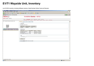
- 194. E1/T1 Wayside Unit Set up and configuration of the E1/T1 Wayside Unit. Click on the different sub page tabs for more information. If Configuration, Fault or Performance are selected from the Menu bar, with the E1/T1 Wayside Unit highlighted, the Configuration, Fault or Performance data for the E1/T1 Wayside Unit are displayed.
- 195. E1/T1 Wayside Unit, Inventory List of EOW Inventory including Software versions, Serial Number Article Code and Revision.
- 196. E1/T1 Wayside Unit, Port 1 Wayside traffic can be inserted in dedicated Section Overhead bytes. Note! If one or more of the bytes used for wayside traffic are already assigned for 64kb/s channels (Engineering Orderwire or 4x64kb/s AUX Units), Wayside traffic can not be enabled. In this case the 64kb/s channels must be reassigned to bytes not used for wayside traffic. See Engineering Orderwire Unit and 4x64kb/s Unit setup. The bytes may also be used by SU Ethernet Wayside traffic. E1 or T1 wayside traffic can be selected. By checking the Enable E1/T1 check box, the SOH/TOH chart is displayed. If T1 is selected, the interface cable length has to be selected.
- 197. Pull Down Menus: Direction Main Traffic Channel Selection of Wayside traffic direction. Alternatives: Antenna Direction (The name for the Antenna Directions that was entered under Unit Housekeeping will appear in the Pull Down Menu) Selection of Main Traffic Channel. Dependent on the number of Regular Channels Function Buttons Set Setting of Wayside parameters Check Boxes: Enable E1/T1 Enabling Wayside traffic
- 198. E1/T1 Wayside Unit, Port 2 Wayside traffic can be inserted in dedicated Section Overhead bytes. Note! If one or more of the bytes used for wayside traffic are already assigned for 64kb/s channels (Engineering Orderwire or 4x64kb/s AUX Units), Wayside traffic can not be enabled. In this case the 64kb/s channels must be reassigned to bytes not used for wayside traffic. See Engineering Orderwire Unit and 4x64kb/s Unit setup. The bytes may also be used by SU Ethernet Wayside traffic. E1 or T1 wayside traffic can be selected. By checking the Enable E1/T1 check box, the SOH/TOH chart is displayed. If T1 is selected, the interface cable length has to be selected.
- 199. Pull Down Menus: Direction Main Traffic Channel Selection of Wayside traffic direction. Alternatives: Antenna Direction (The name for the Antenna Directions that was entered under Unit Housekeeping will appear in the Pull Down Menu) Selection of Main Traffic Channel. Dependent on the number of Regular Channels Function Buttons Set Setting of Wayside parameters Check Boxes: Enable E1/T1 Enabling Wayside traffic
- 200. E1/T1 Wayside Unit, Looping Four different loops can be activated on the E1/T1 Wayside Unit. One near end loop for each Port and one corresponding far end loop. Note! When a loop is activated, traffic on the Port will be broken. Before activating a loop, the Time Out Value must be selected. The loop is activated by clicking the actual arrow and the symbol will turn red. Only one loop can be active at the time. The active loop must be deactivated, before the other loop can be activated.
- 201. Function Buttons: Get Start Polling Stop Polling Get Loop Status Start Loop Status Polling Stop Loop Status Polling Pull Down Menus: Time Out Value Setting of loop Time Out values; Week, Day, Hour, Min, Sec
- 202. E1/T1 Wayside Unit, PRBS A PRBS signal can be inserted instead of the regular traffic to test the E1T1 Wayside Unit. The E1/T1 Wayside Unit contains two PRBS Generators and two Checkers. Only one Generator and one Checker are active at the time. When one checker is enabled, by clicking the arrow on the block diagram, the other will automatically be disabled. The Generator is started by clicking the Generator arrow on the block diagram. The arrow turns red. Note! When the Generator is activated, traffic on this Port will be broken.
- 203. Function Buttons: Active Generator Set Active Checker Set Single Bit Error Active Checker Reset Get Start Polling Stop Polling Sets parameters on the active generator. Sets parameters on the active checker. Inserts a single error bit in the Signal Frame. This is a helpful feature to check the system (check that the total errors are increased by one when this button is pushed). Resets the error counting on the Checker. Gets Error Status Starts Error polling Stop Error Polling Pull Down Menus: Active Generator Pattern Active Checker Pattern Setting of signal pattern. Available pattern: PRBS 2*23-1 Setting of signal pattern. Available pattern: PRBS 2*23-1 Check Boxes Active Generator Inverted Active Checker Inverted Inverts the Generator signal Inverts the Checker signal
- 204. RIU Set up and configuration of the Radio Interface Unit. Click on the different sub pages for more information. If Configuration, Fault or Performance are selected from the Menu bar, with the RIU Unit highlighted, the Configuration, Fault or Performance data for the RIU Unit are displayed.
- 205. RIU, Inventory List of RIU Inventory including Software versions, Serial Number Article Code and Revision. Input Field: Log Log available for user defined text input Function Button: Set Log Saves the text entries to the Log
- 206. RIU, Looping One loop can be activated on the RIU. Note! When the loop is activated, traffic on this RIU will be broken. Before activating the loop, the Time Out Value must be selected. The loop is activated by clicking the arrow and the symbol will turn red.
- 207. Function Buttons: Get Start Polling Stop Polling Get Loop Status Start Loop Status Polling Stop Loop Status Polling Pull Down Menus: Time Out Value Setting of loop Time Out values; Week, Day, Hour, Min, Sec
- 208. RIU, BER Threshold Setting of thresholds for Bit Error Rate alarms
- 209. Pull Down Menus: HBER LBER Early Warning (EW) Selection of High Bit Error Rate Threshold. Alternatives: 1.0E-3, 1.0E-4, 1.0E-5, 1.0E-6 or SES (Severely Errored Seconds) Selection of Low Bit Error Rate Threshold. Alternatives: 1.0E-6, 1.0E-7, 1.0E-8 or 1.0E-9 Selection of Early Warning Threshold. Alternatives: 1.0E-9, 1.0E-10, 1.0E-11, 1.0E-12 or RPS optimized Function Buttons Set Setting of Bit Error Rate Parameters Check Box: Insert AIS on HBER Insert AIS signal if HBER occurs
- 210. FAN Displays the Fan status. Fan 1 is the fan nearest to the Front Panel. Fan 1 and 2 are used for temperature control of the Plug-in Units. Fan 3 is used for temperature control of the Motherboard. If Configuration, Fault or Performance are selected from the Menu bar, with the Fan Unit highlighted, the Configuration, Fault or Performance data for the Fan Unit are displayed. Function Buttons: Get Start Polling Stop Polling Get the current Fan status Starts polling the Fan status Stops polling the Fan status
- 211. SU Set up and configuration of the Radio Interface Unit. Click on the different sub pages for more information. If Configuration, Fault or Performance are selected from the Menu bar, with the SU Unit highlighted, the Configuration, Fault or Performance data for the SU Unit are displayed. Note! Dependent on the system configuration, different sub pages are visible. When the system is configured as Metro (See Housekeeping), the sub pages "Inventory" and "Wayside" are visible. In addition the sub pages; "Looping", "Ethernet" and "GFP" are visible when wayside is enabled. When the System is configured as IP (See Housekeeping), "Inventory", "Looping", "PRBS", "Ethernet", "GFP" and "POH" sub pages are visible. When the System is configured as XPAND (See Housekeeping), and "Ethernet mapped in E1 (T1)" is enabled, the sub pages "Inventory", "Looping", "Ethernet" and "GFP" are visible.
- 212. Metro
- 213. IP
- 214. XPAND
- 215. SU, Inventory-METRO List of SU Inventory including Software versions, Serial Number Article Code and Revision.
- 216. SU, Wayside-METRO 2Mb/s Ethernet Wayside traffic can be inserted in dedicated Section Overhead bytes. Note! If one or more of the bytes used for wayside traffic (yellow) are already assigned for 64kb/s channels (Engineering Orderwire or 4x64kb/s AUX Units), 2Mb/s Ethernet traffic can not be enabled. In this case the 64kb/s channels must be reassigned to bytes not used for wayside traffic. See Engineering Orderwire Unit and 4x64kb/s Unit setup.
- 217. Check Box 2Mb/s Ethernet Enable Check this box to enable 2Mb/s wayside Function Buttons: Set Set the selected configuration Pull Down Menus: Direction Main traffic channel Antenna direction (name) Select Main traffic channel number
- 218. SU, Looping-METRO Two different loops can be activated on the SU (Near end and Far end). Note! When a loop is activated, Ethernet traffic on the SU will be broken. Before activating a loop, the Time Out Value must be selected. The loop is activated by clicking the actual arrow and the symbol will turn red. Only one loop can be active at the time. The active loop must be deactivated, before the other loop can be activated.
- 219. Function Buttons: Get Start Polling Stop Polling Get Loop Status Start Loop Status Polling Stop Loop Status Polling Pull Down Menus: Time Out Value Setting of loop Time Out values; Week, Day, Hour, Min, Sec
- 220. SU, Ethernet-METRO The Ethernet port (ETH2), can be configured as 10/100 Base-T (half or full duplex).
- 221. Function Buttons: Set Get Start Polling Stop Polling Set selected parameters Get Ethernet link status Start Ethernet link status Polling Stop Ethernet link status Polling Check Boxes: Flow control Enable Port Link loss forwarding Enable/Disable Flow control for the Ethernet Port. Enable/Disable the Ethernet Port. Enable/Disable Link loss forwarding. See description below Pull Down Menus: Port Link speed and duplex MAC address aging timeout Capacity Select port number to configure. Options; 1 to 5 Auto, 10/100 Half/Full Duplex Selectable: OFF, ON-5min or ON-15sec Select the capacity to be allocated for Ethernet traffic. Link Loss Forwarding (LLF) With this function enabled, a loss of signal on one Network Element (e.g. cable failure/unplugged) will be detected on the corresponding Network Element and shut down this Ethernet port.
- 222. Note! Link Loss Forwarding must be enabled on both corresponding Network Elements In the figure below, an Ethernet link loss will be detected on NE2. A LLF signal will be sent to NE1 and the Ethernet port will be shut down. In the figure below, a loss of signal will be detected on both Network Elements and the Ethernet ports will be shut down. The LLF function is specially useful in ring protected systems. In the example below, a cable is broken between Router B and NE2. Link Loss failure will be detected on NE1 and transmission shut down. The Ethernet traffic between Router A and B will be routed via NE3 and NE4.
- 223. Note! If the Ethernet ports are forced down due to signal loss (LLF enabled), application of a traffic loop on one of the NEs may result in unwanted activation of the Ethernet ports on the NE in question as well as on the corresponding NE. If it is required that the Ethernet ports stay disabled, the ports must be manually disabled on the NEs or on the periferal equipment.
- 224. SU, GFP-METRO Generic Framing Procedure (GFP). Layer 2 encapsulation scheme for Ethernet data traffic.
- 225. Function Buttons: Reset Get Start Polling Stop Polling Reset GFP status Get GFP status Start GFP status Polling Stop GFP status Polling
- 226. SU, Inventory-IP List of SU Inventory including Software versions, Serial Number Article Code and Revision.
- 227. SU, Looping-IP Two different loops can be activated on the SU (Near end and Far end). Note! When a loop is activated, Ethernet traffic on the SU will be broken. Before activating a loop, the Time Out Value must be selected. The loop is activated by clicking the actual arrow and the symbol will turn red. Only one loop can be active at the time. The active loop must be deactivated, before the other loop can be activated.
- 228. Function Buttons: Get Start Polling Stop Polling Get Loop Status Start Loop Status Polling Stop Loop Status Polling Pull Down Menus: Time Out Value Setting of loop Time Out values; Week, Day, Hour, Min, Sec
- 229. SU, PRBS-IP A PRBS signal can be inserted instead of the regular traffic to test the SU. The SU contains one Generator and one Checker. The black arrow on the diagram indicates the Generator. The green arrow is the active Checker. The Generator is started by clicking the Generator arrow on the block diagram. The arrow turns red. Note! When the Generator is activated, Ethernet traffic on the SU will be broken.
- 231. Function Buttons: Generator Set Checker Set Single Bit Error Active Checker Reset Get Start Polling Setting of Generator parameters Setting of Checker parameters Inserts a single error bit in the Signal Frame. This is a helpful feature to check the system (check that the total errors are increased by one when this button is pushed). Resets the error counting on the Checker. Gets Error Status Starts Error polling. Stop Polling Stop Error Polling Pull Down Menus: Generator Pattern Checker Pattern Signal pattern selection. Available pattern: PRBS 2*23-1 Signal pattern selection. Available pattern: PRBS 2*23-1 Check Boxes Generator Inverted Checker Inverted Inverts the Generator signal Inverts the Checker signal
- 232. SU, Ethernet-IP The Ethernet port (ETH2), can be configured as 10/100 Base-T (half or full duplex).
- 233. Function Buttons: Set Get Start Polling Stop Polling Set selected parameters Get Ethernet link status Start Ethernet link status Polling Stop Ethernet link status Polling Check Boxes: Flow control Enable Port Link loss forwarding Enable/Disable Flow control for the Ethernet Port. Enable/Disable the Ethernet Port. Enable/Disable Link loss forwarding. See description below Pull Down Menus: Port Link speed and duplex MAC address aging timeout Capacity Select port number to configure. Options; 1 to 5 Auto, 10/100 Half/Full Duplex Selectable: OFF, ON-5min or ON-15sec Select the capacity to be allocated for Ethernet traffic. Link Loss Forwarding (LLF) With this function enabled, a loss of signal on one Network Element (e.g. cable failure/unplugged) will be detected on the corresponding Network Element and shut down this Ethernet port.
- 234. Note! Link Loss Forwarding must be enabled on both corresponding Network Elements In the figure below, an Ethernet link loss will be detected on NE2. A LLF signal will be sent to NE1 and the Ethernet port will be shut down. In the figure below, a loss of signal will be detected on both Network Elements and the Ethernet ports will be shut down. The LLF function is specially useful in ring protected systems. In the example below, a cable is broken between Router B and NE2. Link Loss failure will be detected on NE1 and transmission shut down. The Ethernet traffic between Router A and B will be routed via NE3 and NE4.
- 235. Note! If the Ethernet ports are forced down due to signal loss (LLF enabled), application of a traffic loop on one of the NEs may result in unwanted activation of the Ethernet ports on the NE in question as well as on the corresponding NE. If it is required that the Ethernet ports stay disabled, the ports must be manually disabled on the NEs or on the periferal equipment.
- 236. SU, GFP-IP Generic Framing Procedure (GFP). Layer 2 encapsulation scheme for Ethernet data traffic.
- 237. Function Buttons: Reset Get Start Polling Stop Polling Reset GFP status Get GFP status Start GFP status Polling Stop GFP status Polling
- 238. SU, POH-IP Path Overhead (POH)
- 239. Function Buttons: Get Start Polling Stop Polling Get POH status Start POH status Polling Stop POH status Polling
- 240. SU, Inventory-XPAND List of SU Inventory including Software versions, Serial Number Article Code and Revision.
- 241. SU, Looping-XPAND Two different loops can be activated on the SU (Near end and Far end). Note! When a loop is activated, Ethernet traffic on the SU will be broken. Before activating a loop, the Time Out Value must be selected. The loop is activated by clicking the actual arrow and the symbol will turn red. Only one loop can be active at the time. The active loop must be deactivated, before the other loop can be activated.
- 242. Function Buttons: Get Start Polling Stop Polling Get Loop Status Start Loop Status Polling Stop Loop Status Polling Pull Down Menus: Time Out Value Setting of loop Time Out values; Week, Day, Hour, Min, Sec
- 243. SU, Ethernet-XPAND The Ethernet port (ETH2), can be configured as 10/100 Base-T (half or full duplex).
- 244. Function Buttons: Set Get Start Polling Stop Polling Set selected parameters Get Ethernet link status Start Ethernet link status Polling Stop Ethernet link status Polling Check Boxes: Flow control Enable Port Link loss forwarding Enable/Disable Flow control for the Ethernet Port. Enable/Disable the Ethernet Port. Enable/Disable Link loss forwarding. See description below Pull Down Menus: Port Link speed and duplex MAC address aging timeout Capacity Select port number to configure. Options; 1 to 5 Auto, 10/100 Half/Full Duplex Selectable: OFF, ON-5min or ON-15sec Select the capacity to be allocated for Ethernet traffic. Link Loss Forwarding (LLF) With this function enabled, a loss of signal on one Network Element (e.g. cable failure/unplugged) will be detected on the corresponding Network Element and shut down this Ethernet port.
- 245. Note! Link Loss Forwarding must be enabled on both corresponding Network Elements In the figure below, an Ethernet link loss will be detected on NE2. A LLF signal will be sent to NE1 and the Ethernet port will be shut down. In the figure below, a loss of signal will be detected on both Network Elements and the Ethernet ports will be shut down. The LLF function is specially useful in ring protected systems. In the example below, a cable is broken between Router B and NE2. Link Loss failure will be detected on NE1 and transmission shut down. The Ethernet traffic between Router A and B will be routed via NE3 and NE4.
- 246. Note! If the Ethernet ports are forced down due to signal loss (LLF enabled), application of a traffic loop on one of the NEs may result in unwanted activation of the Ethernet ports on the NE in question as well as on the corresponding NE. If it is required that the Ethernet ports stay disabled, the ports must be manually disabled on the NEs or on the periferal equipment.
- 247. SU, GFP-XPAND Generic Framing Procedure (GFP). Layer 2 encapsulation scheme for Ethernet data traffic.
- 248. Function Buttons: Reset Get Start Polling Stop Polling Reset GFP status Get GFP status Start GFP status Polling Stop GFP status Polling
- 249. Plug-in Units Available Plug-in Units: Line Interface Unit (LIU) LIU 3xDS3/E3 LIU 12xE1 LIU 25xE1 LIU 8xT1 LIU 16xT1 Gigabit Ethernet Unit DXC Unit
- 250. LIU Set up and configuration of the Line Interface Unit. Click on the different sub pages for more information. If Configuration, Fault or Performance are selected from the Menu bar, with the LIU Unit highlighted, the Configuration, Fault or Performance data for the LIU Unit are displayed.
- 251. LIU, Inventory List of LIU Inventory including Software versions, Serial Number Article Code and Revision. Input Field: Log Log available for user defined text input Function Button: Set Log Saves the text entries to the Log
- 252. LIU, Looping Two different loops can be activated on the LIU (Near end and Far end). Note! When a loop is activated, traffic on this LIU will be broken. Before activating a loop, the Time Out Value must be selected. The loop is activated by clicking the actual arrow and the symbol will turn red. Only one loop can be active at the time. The active loop must be deactivated, before the other loop can be activated.
- 253. Function Buttons: Get Start Polling Stop Polling Get Loop Status Start Loop Status Polling Stop Loop Status Polling Pull Down Menus: Time Out Value Setting of loop Time Out values; Week, Day, Hour, Min, Sec
- 254. LIU, PRBS A PRBS signal can be inserted instead of the regular traffic to test the LIU. The LIU contains one Generator and two Checkers. Only one Checker is active at the time. When one checker is enabled, by clicking the arrow on the block diagram, the other will automatically be disabled. The red arrow on the diagram indicates the Generator. The green arrow is the active Checker. The black arrow is the inactive Checker. The Generator is started by clicking the Generator arrow on the block diagram. The arrow turns red. Note! When the Generator is activated, traffic on this LIU will be broken. Activate the uppermost Checker, to test the Customer Interface side of the LIU. Note! A loop must be activated at the Customer interface side. Activate the rightmost Checker, to test the IFU Basic Frame interface side of the LIU. Note! A loop must be activated at the IFU Basic Frame interface side.
- 255. Function Buttons: Generator Set Checker Set Single Bit Error Checker Reset Get Start Polling Stop Polling Setting of Generator parameters Setting of Checker parameters Inserts a single error bit in the Signal Frame. This is a helpful feature to check the system (check that the total errors are increased by one when this button is pushed). Resets the error counting on the Checker. Gets Error Status Starts Error polling. Stop Error Polling Pull Down Menus: Generator Pattern Checker Pattern Signal pattern selection. Available pattern: PRBS 2*23-1 Signal pattern selection. Available pattern: PRBS 2*23-1 Check Boxes Generator Inverted Checker Inverted Inverts the Generator signal Inverts the Checker signal
- 256. LIU, Path Trace The Path Trace functionality and the AIS (Alarm Indicator Signal) functionality are used to test that the received signal frames are the frames we want to receive (correct routing, frequency alignment. . . . ). This is done by either inserting a fixed byte or an user defined ASCII sting in the J0 slot in the RSOH (Send). The radio that receives the signal frames must have the same Trace string (J0) defined. If there is a mismatch, an AIS can be inserted (if configured). An AIS can also be inserted if the HBER threshold is exceeded.
- 257. Enable receive Enable Receive Trace string Function Buttons: Set (Send) Set (Receive) Get Start Polling Stop Polling Set Path Trace signal to send Set Path Trace signal expected to receive Get Status Start polling Status Stop polling Status Input Fields: Send Trace string Receive Expected User defined ASCII string max. 15 characters User defined ASCII string max. 15 characters Check Boxes: Enable send Enable Send Trace string
- 258. LIU, AIS The Path Trace functionality and the AIS (Alarm Indicator Signal) functionality are used to verify that the received signal frames are the frames we want to receive (correct routing, frequency alignment. . . . ). This is done by either inserting a fixed byte or a user defined ASCII string in the J0 slot in the RSOH. This is done from the path trace sheet. The radio that receives the signal frames must have the same Trace string (J0) defined in the AIS insert sheet. If there is a mismatch, an AIS can be inserted (if configured). An AIS can also be inserted if the HBER threshold is exceeded (configured on the RIU).
- 259. Check Boxes: Insert AIS on Trace Identifier Mismatch (TIM) Remove Delay Enabled When this box is checked, an Alarm Indicating Signal is inserted when there is a mismatch between the Path Trace string or fixed byte sent and the expected Receive signal Remove AIS delay Pull Down Menu: AIS remove delay (in sec) Setting of AIS remove dela: 0-300 seconds Function Button: Set Set AIS parameters
- 260. LIU, DCC Data Communication Channels can be inserted into the SOH. Single or multiple SOH bytes (D1-D3 or D4-D12) can be selected. Check Box: Enable Enable Data Communication Channels Pull Down Menu: Coding Select Coding. Alternatives: NRZ, NRZI Function Button: Set Set DCC parameters
- 261. LIU 3xDS3/E3 Set up and configuration of the LIU 3xDS3/E3. Click on the different sub pages for more information. If Configuration, Fault or Performance are selected from the Menu bar, with the LIU 3xDS3/E3 highlighted, the Configuration, Fault or Performance data for the LIU 3xDS3/E3 are displayed.
- 262. LIU 3xDS3/E3, Inventory List of LIU 3xDS3/E3 Inventory including Software versions, Serial Number Article Code and Revision. Input Field: Log Log available for user defined text input Function Button: Set Log Saves the text entries to the Log
- 263. LIU 3xDS3/E3, Looping Six different loops can be activated on the LIU (3 Near end and 3 Far end). Note! When a loop is activated, traffic on the Port will be broken. Before activating a loop, the Time Out Value must be selected. The loop is activated by clicking the actual arrow and the symbol will turn red. Only one loop can be active at the time. The active loop must be deactivated, before the other loop can be activated.
- 264. Function Buttons: Get Start Polling Stop Polling Get Loop Status Start Loop Status Polling Stop Loop Status Polling Pull Down Menus: Time Out Value Setting of loop Time Out values; Week, Day, Hour, Min, Sec
- 265. LIU 3xDS3/E3, PRBS A PRBS signal can be inserted instead of the regular traffic to test the LIU 3xDS3/E3. The LIU 3xDS3/E3 contains two Generators and two Checkers. Only one Checker is active at the time. When one checker is enabled, by clicking the arrow on the block diagram, the other will automatically be disabled. The red arrow on the diagram indicates the active Generator. The green arrow is the active Checker. The black arrow is the inactive Checker. The Generator is started by clicking the Generator arrow on the block diagram. The arrow turns red. Note! When the Generator is activated, traffic on this Port will be broken. Activate the uppermost Checker, to test the Customer Interface side of the LIU 3xDS3/E3. Note! A loop must be activated at the Customer interface side. Activate the rightmost Checker, to test the IFU Basic Frame interface side of the LIU 3xDS3/E3. Note! A loop must be activated at the IFU Basic Frame interface side.
- 266. Function Buttons: Active Generator Set Active Checker Set Single Bit Error Active Checker Reset Get Start Polling Stop Polling Setting of Generator parameters Setting of Checker parameters Inserts a single error bit in the Signal Frame. This is a helpful feature to check the system (check that the total errors are increased by one when this button is pushed). Resets the error counting on the Checker. Gets Error Status Starts Error polling. Stop Error Polling Pull Down Menus: Active Generator Pattern Active Checker Pattern Port Signal pattern selection. Available pattern: PRBS 2*23-1 Signal pattern selection. Available pattern: PRBS 2*23-1 Select the port to be checked. Alternatives; 1, 2 or 3
- 267. LIU 3xDS3/E3, Ports All ports can be enabled / disabled individually. E3 (ETSI) screenshot (ETSI or ANSI configuration is selected from Housekeeping) See screenshot below for DS3 (ANSI).
- 268. Function Buttons: Get Set Enable All Ports Disable All Ports Get Port Status Set parameters for actual port Enables all ports Disables all ports Pull Down Menus: Cable Length Select "<=225 feet" or ">225 feet" DS3 (ANSI) screenshot (ETSI or ANSI configuration is selected from Housekeeping) See screenshot abow for E3 (ETSI). Line AIS insertion Select "Enable AIS on LOS" or "Enable AIS on LOS/OOF"
- 269. LIU 12xE1 Set up and configuration of the LIU 12xE1. Click on the different sub pages for more information. If Configuration, Fault or Performance are selected from the Menu bar, with the LIU Unit highlighted, the Configuration, Fault or Performance data for the LIU Unit are displayed.
- 270. LIU 12xE1, Inventory List of LIU 12xE1 Inventory including Software versions, Serial Number Article Code and Revision. Input Field: Log Log available for user defined text input Function Button: Set Log Saves the text entries to the Log
- 271. LIU 12xE1, Looping 24 loops can be activated on the LIU 12xE1 Unit, two for each E1 Port (Near end and Far end). Note! When a loop is activated, traffic on the actual port will be broken. Before activating a loop, the Time Out Value must be selected. The loop is activated by clicking the actual arrow and the symbol will turn red. Only one loop can be active one each port at the time. The active loop must be deactivated, before the other loop can be activated.
- 272. Function Buttons: Get Start Polling Stop Polling Get Loop Status Start Loop Status Polling Stop Loop Status Polling Pull Down Menus: Time Out Value Setting of loop Time Out values; Week, Day, Hour, Min, Sec
- 273. LIU 12xE1, PRBS A PRBS signal can be inserted instead of the regular traffic to test the LIU 12xE1 Ports. The LIU 12xE1 contains one PRBS Generator and two Checkers. Only one Checker is active at the time. When one checker is enabled, by clicking the arrow on the block diagram, the other will automatically be disabled. A red arrow on the diagram indicates an active Generator. A green arrow is an active Checker. The Generator is started by clicking the Generator arrow on the block diagram. The arrow turns red. Note! When the Generator is activated, traffic on the actual port will be broken. Activate the uppermost Checker, to test the Customer Interface side. Note! A near end loop must be activated. Activate the rightmost Checker, to test the IFU Basic Frame interface side. Note! A far end loop must be activated.
- 274. Function Buttons: Generator Set Checker Set Single Bit Error Checker Reset Get Start Polling Stop Polling Setting of Generator parameters Setting of Checker parameters Inserts a single error bit in the Signal Frame. This is a helpful feature to check the system (check that the total errors are increased by one when this button is pushed). Resets the error counting on the Checker. Gets Error Status Starts Error polling. Stop Error Polling Pull Down Menus: Port Generator Pattern Checker Pattern The port where the PRBS signal is to be inserted. Alternatives: 1 to 12. Signal pattern selection. Available pattern: PRBS 2*23-1 Ssignal pattern selection. Available pattern: PRBS 2*23-1 Check Boxes Generator Inverted Checker Inverted Inverts the Generator signal Inverts the Checker signal
- 275. LIU 12xE1, Ports All ports can be enabled / disabled individually.
- 276. Set Enable All Ports Disable All Ports Set parameters for actual port Enables all ports Disables all ports Function Buttons: Get Get Port Status
- 277. LIU 25xE1 Set up and configuration of the LIU 25xE1. Click on the different sub pages for more information. If Configuration, Fault or Performance are selected from the Menu bar, with the LIU Unit highlighted, the Configuration, Fault or Performance data for the LIU Unit are displayed.
- 278. LIU 25xE1, Inventory List of LIU 25xE1 Inventory including Software versions, Serial Number Article Code and Revision. Input Field: Log Log available for user defined text input Function Button: Set Log Saves the text entries to the Log
- 279. LIU 25xE1, Looping 50 loops can be activated on the LIU 25xE1 Unit, two for each E1 Port (Near end and Far end). Note! When a loop is activated, traffic on the actual port will be broken. Before activating a loop, the Time Out Value must be selected. The loop is activated by clicking the actual arrow and the symbol will turn red. Only one loop can be active one each port at the time. The active loop must be deactivated, before the other loop can be activated.
- 280. Function Buttons: Get Start Polling Stop Polling Get Loop Status Start Loop Status Polling Stop Loop Status Polling Pull Down Menus: Time Out Value Setting of loop Time Out values; Week, Day, Hour, Min, Sec
- 281. LIU 25xE1, PRBS A PRBS signal can be inserted instead of the regular traffic to test the LIU 25xE1 Ports. The LIU 25xE1 contains one PRBS Generator and two Checkers. Only one Checker is active at the time. When one checker is enabled, by clicking the arrow on the block diagram, the other will automatically be disabled. A red arrow on the diagram indicates an active Generator. A green arrow is an active Checker. The Generator is started by clicking the Generator arrow on the block diagram. The arrow turns red. Note! When the Generator is activated, traffic on the actual port will be broken. Activate the uppermost Checker, to test the Customer Interface side. Note! A near end loop must be activated. Activate the rightmost Checker, to test the IFU Basic Frame interface side. Note! A far end loop must be activated.
- 282. Function Buttons: Generator Set Checker Set Single Bit Error Checker Reset Get Start Polling Stop Polling Setting of Generator parameters Setting of Checker parameters Inserts a single error bit in the Signal Frame. This is a helpful feature to check the system (check that the total errors are increased by one when this button is pushed). Resets the error counting on the Checker. Gets Error Status Starts Error polling. Stop Error Polling Pull Down Menus: Port Generator Pattern Checker Pattern The port where the PRBS signal is to be inserted. Alternatives: 1 to 25. Signal pattern selection. Available pattern: PRBS 2*23-1 Ssignal pattern selection. Available pattern: PRBS 2*23-1 Check Boxes Generator Inverted Checker Inverted Inverts the Generator signal Inverts the Checker signal
- 283. LIU 25xE1, Ports All ports can be enabled / disabled individually.
- 284. Set Enable All Ports Disable All Ports Set parameters for actual port Enables all ports Disables all ports Function Buttons: Get Get Port Status
- 285. Gigabit Ethernet Interface Unit Set up and configuration of the Gigabit Ethernet Interface Unit. Click on the different sub page tabs for more information. If Configuration, Fault or Performance are selected from the Menu bar, with the Gigabit Ethernet Interface Unit highlighted, the Configuration, Fault or Performance data for the Gigabit Ethernet Interface Unit are displayed.
- 286. Gigabit Ethernet Unit, Inventory List of Gigabit Ethernet Unit Inventory including Software versions, Serial Number, Article Code and Revision. Input Field: Log Log available for user defined text input Function Button: Set Log Saves the text entries to the Log
- 287. Gigabit Ethernet Unit, Looping Two different loops can be activated on the Gigabit Ethernet Unit (Near end and Far end). Note! When a loop is activated, traffic on the Gigabit Ethernet Unit will be broken. Before activating a loop, the Time Out Value must be selected. The loop is activated by clicking the actual arrow and the symbol will turn red. Only one loop can be active at the time. The active loop must be deactivated, before the other loop can be activated. Egress port swap function Output signal to Port 1 will be swapped with Port 2 and vice versa, in order to prevent the test signal to be sent back to the transmitting port. The same applies to Port 3 and Port 4 (Port 5).
- 288. Function Buttons: Get Start Polling Stop Polling Get Loop Status Start Loop Status Polling Stop Loop Status Polling Pull Down Menus: Time Out Value Setting of loop Time Out values; Week, Day, Hour, Min, Sec
- 289. Gigabit Ethernet Unit, Ports All ports can be configured individually Port 1 to 3 can be configured as 10/100 Base-T (half or full duplex). Port 4 can be configured as 10/100/1000 Base-T (half or full duplex). Port 5 is intended for optical interface by means of an SFP module (1000 Base-X) Note! Only one 1000 Mb/s port can be enabled at the time. Port 1-4 Screenshot
- 290. Port 5 Screenshot Function Buttons: Set Port (1-5) Get Set parameters for actual port Get Port Status
- 291. Pull Down Menus: Port Speed Ingress rate Select port number to configure. Options; 1 to 5 Auto, 10/100 Half/Full Duplex for Port 1 to 3, and in addition for Port 4; 1000 Full Duplex. Port 5, SFP, is 1000 Base-X only. Stepwise limits from 500 kb/s to 83 Mb/s or Not Limited (100 Mb/s or link capacity) for Port 1 to 3. Stepwise from 500 kb/s to 125 Mb/s or Not Limited (link capacity) for Port 4 and 5. See Ethernet page; Ingress rate limiting Check Boxes: Flow control Link loss forwarding Automatic laser shutdown (Port 5) Enable/Disable for Port 1 to 4. This is available only when the Ingress Rate is activated. Note that Burst drop mode must be selected for proper operation. See Ethernet page. Enable/Disable Link loss forwarding. See description below Enable/Disable Automatic laser shutdown. This is a function designed for eye safety purposes, according to ITU-T rec. G.958. When this box is checked the laser will shut down after a short period of time, if loss of signal from far end is detected. After a waiting time period the laser will restart automatically. See Appendix; Gigabit Ethernet Configuration for further details. Link Loss Forwarding (LLF) With this function enabled, a loss of signal on one Network Element (e.g. cable failure/unplugged) will be detected on the corresponding Network Element and shut down this Ethernet port. Note! Link Loss Forwarding must be enabled on both corresponding Network Elements In the figure below, an Ethernet link loss will be detected on NE2. A LLF signal will be sent to NE1 and the Ethernet port will be shut down. In the figure below, a loss of signal will be detected on both Network Elements and the Ethernet ports will be shut down.
- 292. The LLF function is specially useful in ring protected systems. In the example below, a cable is broken between Router B and NE2. Link Loss failure will be detected on NE1 and transmission shut down. The Ethernet traffic between Router A and B will be routed via NE3 and NE4. Note! If the Ethernet ports are forced down due to signal loss (LLF enabled), application of a traffic loop on one of the NEs may result in unwanted activation of the Ethernet ports on the NE in question as well as on the corresponding NE. If it is required that the Ethernet ports stay disabled, the ports must be manually disabled on the NEs or on the periferal equipment.
- 293. Gigabit Ethernet Unit, Ethernet configuration Function Buttons: Set Set selected parameters Pull Down Menus: MAC address aging timeout Ingress rate limiting Select MAC address aging timeout. Options; 15 sec, 5 min or Learning off. Select Ingress rate limiting drop mode. Options; Continous drop or Burst drop. Ref appendix; Gigabit Ethernet Configuration
- 294. Gigabit Ethernet Unit, QoS (Quality of Service) Used for traffic prioritizing. Function Buttons: Set Set selected parameters
- 295. Pull Down Menus: QoS priority scheme QoS scheduling mode The QoS priority scheme has 4 options: OFF, Port, VLAN, DSCP/TOS OFF All traffic has equal priority. Port (Ethernet input ports) Each port can be given priority 0 to 3 individually. Click the actual decimal value in the screen and select required priority from pull down menu. VLAN (802.1p user priority) VLAN user priority is represented by 8 decimal values (0-7), which is mapped into four traffic queues. Click the actual decimal value in the screen and select required priority from pull down menu. DSCP/TOS (IPv4/IPv6) DSCP is represented by 64 decimal values (0-63), which is mapped into four traffic queues. Click the actual decimal value in the screen and select required priority from pull down menu. Options; Fair queueing or Strict queueing Fair queueing An 8, 4, 2, 1 weighting is applied to the four priorities. This approach prevents the lower priority frames from being starved out with only a slight delay to the higher priority frames. Strict queueing All top priority frames egress for a port untill that priority's queue is empty. Then the next lower priority queue's frames egress, etc. This ensures that all high priority frames egress as soon as possible.
- 296. Port (Ethernet input ports)
- 297. VLAN (802.1p user priority)
- 298. DSCP/TOS (IPv4/IPv6)
- 299. Gigabit Ethernet Unit, Capacity VCG (Virtual Link) status Failed or Fuly operational. If status is Failed, ref Fault Finding and Alarm Lists
- 300. Function Buttons: Set Get Set Mapping and Capacity Get Tributary Status Pull Down Menus: Mapping resolution Capacity ETSI alternatives: VC-4, VC-3, VC-12 ANSI alternatives: STS-3C, STS-1, VT 1.5 Alternatives: VC-4: 0, 1 VC-3: 0,1,2,3 VC-12: 0-63 STS-3C: 0,1 STS-1: 0,1,2,3 VT 1.5: 0-64 Check Box LCAS enabled By shecking tif box, LCAS (Link Capacity Adjustment Scheme) is enabled.
- 301. Gigabit Ethernet Unit, Statistics Statistics for octet packet counters, ingress(Rx value) and egress(Tx value) for ethernet ports. Function Buttons: Get Reset Port Reset All Get Port Status Reset counter on actual Port Reset counter on all Ports Pull Down Menus: Port Select port number to view. Options; 1 to 5
- 302. Gigabit Ethernet Unit, Charts Graphic presentation of Ethernet statistics. Pull Down Menu: Resolution 5sec - 60min Function Buttons: Set Get Set Resolution Get statistics
- 303. DXC Unit Set up and configuration of the DXC Unit. Click on the different sub pages for more information. If Configuration, Fault or Performance are selected from the Menu bar, with the DXC Unit highlighted, the Configuration, Fault or Performance data for the DXC Unit are displayed.
- 304. DXC, Inventory List of DXC Unit Inventory including Software versions, Serial Number Article Code and Revision. Input Field: Log Log available for user defined text input Function Button: Set Log Saves the text entries to the Log
- 305. DXC, Frame Structure Each of the four ports on the DXC must be configured with correct mapping structure. Only configured DXC ports are shown. Each port can have different mapping structure. The following mapping structures are available: SDH (ETSI): STM-1/AU-4/VC-4 STM-1/AU-4/VC-4/3xTUG-3 Where each TUG-3 can be either TU-3/VC-3 or 21xTU-12/VC-12 SONET (ANSI): OC-3 (STS-3)/STS-3c/STS-3c SPE OC-3 (STS-3)/3xSTS-1 Where each STS-1 can be either STS-1 SPE or 21xVT1.5 VT1.5 is available in SW version R4B and later. Configuration of ETSI or ANSI mode is done using the housekeeping wizard The diagram in the screen below, is interactive. Check the 3 x Tug3 check box to explore the different frame structures.
- 306. Function Buttons: Get Set Get frame structure Set frame structure Check Box: 3 x Tug3 Uncheck this box will deselect 3 x Tug3 frame structure Selection Boxes: TU-3 TU-12 Sets the current structure to TU-3 Sets the current structure to TU-12
- 307. DXC, Signal Label The expected signal label (C2 for VC-4, VC-3, STS-3c SPE and STS-1 SPE. V5 for VC-12 and VT1.5) is configured using this page. Select one of the DXC ports using the drop-down list. Select an individual container by clicking inside the square. The received and configured expected signal label on the receive side for the selected container is displayed. A PLM (Payload Mismatch) alarm is generated on containers that have mismatch between received signal label and expected signal label. Received signal label with value equals zero, generates an UNEQ (Unequipped) alarm. UNEQ and PLM alarms are only reported on connected containers. The default expected signal labels are: SDH (ETSI) Mapping: STM-1/AU-4/VC-4: VC-4C2=Asynchronous 140M(12hex) STM-1/AU-4/VC-4/TUG-3/TU-3/VC-3: VC-4C2=TUG Structure(2) VC-3C2= Asynchronous 34/45M(4) STM-1/AU-4/VC-4/TUG-3/TU-12/VC-12: VC-4C2=TUG Structure(2) VC-12V5= Asynchronous 2M(2) SONET (ANSI) Mapping: OC-3 (STS-3)/STS-3c/STS-3c SPE: STS-3c SPEC2=Asynchronous 140M(12hex) OC-3 (STS-3)/STS-1/STS-1 SPE STS-1 SPEC2= Asynchronous DS3(4) OC-3 (STS-3)/STS-1/VT1.5 V1.5V5= Asynchronous DS1(2) VT1.5 is available in SW version R4B and later.
- 309. Pull Down Menus: Port Expected signal label Select Port Select expected signal label Function Button: Set Apply settings
- 310. DXC, Digital X Connect The X-connect functionallity allows the operator to connect two virtuals containers (VC) in different ports. The connections are identified by using the background colour of the ports together with the KLM address of the virtual container. The background colour of a virtual container identifies the source port, while the KLM address identifies the source address. SNCP functionality is identified with a split cell. To enable SNCP connections, the "SNCP connection mode" box must be checked. The SNCP functionality will apply to the same virtual container on all ports. Looping is achieved by connecting VCs on the same port (Traffic Looping). When configuring the cross-connection of containers two modes are available, cross-connection of two containers and cross-connection with SNCP (Path protection). 1. Cross-connection without SNCP: When configuring cross-connections without SNCP the check box SNCP Connection Mode must be unchecked. Select the source container by clicking inside the square for that container. Then select the sink container by clicking inside square for that container. Both containers will be colored dark blue to indicate selection. Press the Connect button. Verify the correct cross-connection before pushing the Set button to apply the setting to the Unit. Traffic looping of a container can be performed by selecting the same container twice, and then push Connect button and Set button. Disconnecting of a connection is done selecting either of the two containers in a connection and push Disconnect button and Set button. Both cross-connected containers will be colored light blue to indicate selection. 2. Cross-connection with SNCP: When configuring cross-connections with SNCP the check box SNCP Connection Mode must be checked. Select the first source container by clicking inside the square for that container. Then select the second source container by clicking inside square for that container. Both containers will be colored dark blue to indicate selection. Clicking inside the third container square selects the sink for the SNCP connection. The container will be colored red to indicate sink selection. Press the Connect button. Verify the correct SNCP cross-connection before pushing the Set button, to apply the setting to the Unit. Disconnecting of a connection is done selecting any of the three containers in a connection and push Disconnect button and Set button. All containers in the selected SNCP connection will be colored light blue to indicate selection. Note: The configuration is not applied to the unit before the Set button is pushed. Several cross-connections and SNCP connections can be configured before the Set button is pushed.
- 311. Function Button: Connect Disconnect Get Set Select the virtual containers to be connected. Press this button to connect the selected virtual containers Select a virtual container which already has an established connection. Press this button to remove the connection Get status Apply the selected connections Check Box: SNCP connectio mode Enable SNCP mode
- 312. DXC, X-Connect Status The X-Connect and SNCP status can be shown for all containers. Select one of the DXC ports using the drop-down list. Select an individual container by clicking inside the square. The SNCP status or X-Connect status for the selection is shown in the text field. Pull Down Menus: Port Select Port
- 313. DXC, SETS Configuration The configuration of the SETS function must be performed to assure correct synchronization in the SDH/SONET network. By default no synchronization sources are selected, and the DXC will be using Local SETS Oscillator. Available clock sources can be added to a priority list by pressing , and removed from the list by . The first entry in the list has highest priority. The priority of a clock source can be changed by clicking or . Maximum three sources can be added to the list. There are two priority tables: One for the T4 DPLL and one for the T0 DPLL. Note! The T4 DPLL priority list is only enabled when “External synchronisation output” is set to T4. If “External synchronisation output” is set to T0, the priority list is "greyed out". The SETS function for T0 can operate in revertive or non-revertive mode when Quality label mode is disabled. If Quality label mode is chosen the switching between the sources will take into account the status of the SSM byte for the sources, and if equal SSM byte also the source priority. If Quality label mode is set to Off, the switching is performed according to priority and validation of the sources only. The quality of the tributary input signal 1 and 2 can be set in the Tributary synchronisation 1 input quality and Tributary synchronisation 2 input quality fields. The quality of the external input signal from the front can be set in the External synchronization input quality field. The source for the external synchronization output can be configured to either T0 or T4. Tributary Syncronisation is available in SW version R4A and later.
- 314. Pull Down Menus: External synchronisation input quality Function Button: Get Set Get status Apply selections
- 315. DXC, SETS Status The status page contains information about the quality of the incoming and outgoing clock signals for all available sources. Each row in the table corresponds to a clock source. A source colored green indicates an active clock source. If the SETS function is in holdover mode the Local oscillator source for T0 will be red. The following status are available: Last changed Source quality/SSM Input source validity Note! The T4 status is only visible if T4 is chosen as the source for the External synchronization output in the SETS Configuration.
- 316. Function Button: Get Start Polling Stop Polling Get synchronization status Start polling of synchronization status Stop polling of synchronization status
- 317. ODU Set up and configuration of the ODU. Click on the different sub pages for more information. If Configuration, Fault or Performance are selected from the Menu bar, with the RIU Unit highlighted, the Configuration, Fault or Performance data for the RIU Unit are displayed.
- 318. ODU, Inventory List of ODU Inventory including Software versions, Serial Number Article Code and Revision.
- 319. Input Field: Log Log available for user defined text input Function Buttons: Reset Set Log Radio reset Saves the text entries to the Log
- 320. ODU, Power The ODU provides a set of RF power control functions: q RF input alarm thresholds can be set such that an alarm is raised when the input level exceeds the upper or lower limits. q ATPC (Automatic Transmit Power Control) is a function for effectively reducing the interference probability in the network. When ATPC is enabled, the output power from the transmitter is automatically controlled. The "ATPC" alarm is generated if ATPC stops functioning. Note that ATPC must be available on both sides of the hop in order to be used. The table "Recommended ATPC Input Reference Level" gives the correct ATPC Input Reference Level as a function of payload, channel spacing and radio frequency. q If ATPC is not enabled, the transmitted output level can be set (MTPC). The transmitter can also be muted. Note! In XPIC configurations it is highly recommended that the ATPC function is enabled. The values in the example below are typical and will vary according to the calculated values from the system propagation.
- 321. Input Field: MTPC Output Level ATPC Input Reference Level Max. Output Level Default Output Level ATPC is disabled and constant manual output level is selected. Output level is automatically adjusted according to the specified ATPC settings. -The desired input level. If ATPC is enabled on the remote transmitter, the remote transmitter will regulate its output power such that the received input level at this receiver is equal to the reference level. See table below for recommended Input Reference Level. -The Transmitters maximum output level (dBm) -The Transmitters default output level (dBm). The output power to be used if ATPC regulation loop fails (The "ATPC" alarm is raised). Check Boxes: MTPC ATPC Mute Output Power ATPC Lower Limit for Mask Enable Manual Transmit Power Control mode Automatic Transmit Power Control mode When checked the Output power is muted Enable the ATPC Lower Limit if the output power is required to comply with the mask defined for the equipment also when operating in ATPC mode. The limit used is the same as the minimum available MTPC output power. Function Button: Apply Apply settings Recommended ATPC Input Reference Level Typical Payload Channel Spacing (MHz) Recommended ATPC "Input Reference Level" L6GHz U6GHz 7GHz 8GHz 10GHz 11GHz 13GHz 15GHz 18GHz 23GHz 26GHz 28GHz 32GHz 38GHz STM-1 / 75 x 1 27.5 - 30 (ACAP) -52 -51 -52 -52 -51 -52 -50 -50 -49 -49 -49 -48 -48 -47 STM-1 / 75 x 1 27.5 - 30 -51 -50 -51 -51 -50 -51 -49 -49 -48 -48 -48 -47 -47 -46 STM-1 / 75 x 1 40 -54 -54 -54 -54 -53 -54 -53 -53 -52 -52 -52 -51 -50 -50 STM-1 / 75 x 1 50 - 56 -59 -58 -59 -59 -58 -59 -56 -56 -55 -55 -54 -53 -53 -53 40 x E1 27.5 - 30 -61 -61 -61 -61 -60 -61 -60 -60 -59 -59 -58 -57 -57 -55 50 x E1 27.5 - 30 -60 -59 -60 -60 -59 -60 -58 -58 -57 -57 -55 -54 -54 -54 20 x E1 13.75 - 15 -64 -63 -64 -64 -63 -64 -62 -62 -61 -61 -61 -60 -60 -59
- 322. ODU, Looping Note! When the loop is activated, traffic on this ODU will be broken. Before activating the loop, the Time Out Value must be selected. The loop is activated by clicking the arrow and the symbol will turn red.
- 323. Function Buttons: Get Start Polling Stop Polling Get Loop Status Start Loop Status Polling Stop Loop Status Polling Pull Down Menus: Time Out Value Setting of loop Time Out values; Week, Day, Hour, Min, Sec
- 324. ODU, Analogues List of analogue levels
- 325. Fault In the Fault menu the alarm status can be monitored. Different functions are provided for acquisition, presentation and storage of alarm data: q Current alarm status and historical alarm information can be collected from the network element and presented in different user interfaces. q Historical alarm data can be logged into a database system. Alarm information can be gathered by two different methods: q Polling: Regularly requests alarm update information from the NE. q Get: Get the current alarm status Colours and symbols are used to indicate the alarm severity of the network element. Each alarm severity class has a corresponding colour and symbol. Note! If you from the Fault menu click one of the IFU Frame Units, the Fault status for that particular Unit is displayed. Click on the sub-menues to explore the functionality.
- 327. Active Displays a list of all active alarms. Note! If you from the Active menu click one of the IFU Frame Units, the active alarm status for that particular Unit is displayed.
- 328. Function Buttons: Apply Filter Set Severity Block Filter alarm list according to selections. Accept selected severity level on selected alarms. Blocked Alarms Get Start Polling Stop Polling Print Table Block alarms that are checked in the list above. View Blocked alarms. Get Alarm Status Start the polling function. The polling sequence will continu until Stop Polling is selected Stops Polling sequence Send the Alarm List to your default printer. Check Boxes: Alarm Select Select alarms to be blocked Pull Down Menues Alarm Filter; Physical Position Alarm Filter; Severity Alarm Filter; State Severity Select all or alarms from a specific unit Filter alarms according to severity level. Filter alarms according to alarm state Select severity level for selected alarms
- 329. All Displays a list of all alarms. Note! If you from the All menu click one of the IFU Frame Units, the alarm status for that particular Unit is displayed.
- 330. Function Buttons: Apply Filter Set Severity Block Filter alarm list according to selections. Accept selected severity level on selected alarms. Blocked Alarms Get Start Polling Stop Polling Print Table Block alarms that are checked in the list above. View Blocked alarms. Get Alarm Status Start the polling function. The polling sequence will continu until Stop Polling is selected Stops Polling sequence Send the Alarm List to your default printer. Check Boxes: Alarm Select Select alarms to be blocked Pull Down Menues Alarm Filter; Physical Position Alarm Filter; Severity Alarm Filter; State Severity Select all or alarms from a specific unit Filter alarms according to severity level. Filter alarms according to alarm state Select severity level for selected alarms
- 331. Event Log The Event Log is a log that displays all events on the Network Element.
- 332. Function Button: Set Mode Remove Entries Accept selected Log Mode Specify the number of entries to be removed from the Events Log Purge Log Print Table Clears the Event Log table Prints the Event Log on a local printer Pull Down Menu Log Mode Select Log Mode. Alternatives: Wrap when full or Halt when full. Note! If "Halt when full" is selected, new events will not be logged when Event log is full. Input Fields: Entries Type in the entry number to be deleted from the Events list
- 333. Performance Different functions are provided for acquisition, presentation and storage of performance data. Cumulative measurements, Registers (15Min, Day and Month) and Thresholds can be selected from the sub-menu. Note! If you from the Performance menu click one of the IFU Frame units, the Performance status for that particular Unit is displayed.
- 334. Definitions Physical Pos Logical Pos Source Reg SES UAS BBE ES Physical position of the unit where the performance measurements are performed Localisation of the unit w.r.t traffic direction SOH bytes (ETSI)/TOH bytes (ANSI) allocated for system monitoring The sequence number of the performance register. Register 0 is the running measurement, register 1 is the latest completed measurement, …, register 16 is the oldest completed measurement. Severely Errored Seconds The number of one-second periods which contain > 30% errored blocks or at least one Severely Disturbed Period (SDP). A SDP is a period where Loss Of Signal (LOS) or Loss Of Frame (LOF) has been detected. SES is a subset of ES. UnAvailable Seconds The number of UnAvailable Seconds. A period of unavailable time begins at the onset of 10 consecutive SES events. These ten seconds are considered to be a part of the unavailable time. A new period of available time begins at the onset of ten consecutive non-SES events. These 10 seconds are considered to be part of available time. Background Block Errors The number of Background Block Errors. An errored block not occurring as part of an SES. Errored Seconds The number of one second periods with one or more errored blocks. Out Of Frame. OOF Seconds: The number of one-second periods with one or more OOF events. Pulses: The number of OOF events detected.
- 335. Registers Displays periodic Measurements. Period measurements are measurements cumulated over a predefined period of time (15 minutes, 24 hours and 1month). The start times of these measurements are also predefined: 15Min measurements start at h:00:00, h:15:00, h:30:00 and h:45:00, where h denotes hour. 24Hour measurements start at each midnight (00:00:00). Month measurements start at midnight at each month transition. Note that the NE is using GMT time, such that the measurement start time is relative to GMT time and not to your PC’s local time. For 15Min measurements the NE keeps the 16 latest periods. For 24Hour and Month measurements only the latest period is kept. Note that the running performance measurements will be reset due to a SW restart on the corresponding board/unit. E.g. restarting a Line Interface Unit will reset all periodic measurements on that unit.
- 336. Definitions Physical Pos Logical Pos Source Reg SES UAS BBE ES OOF Physical position of the unit where the performance measurements are performed Localisation of the unit w.r.t traffic direction SOH bytes (ETSI)/TOH bytes (ANSI) allocated for system monitoring The sequence number of the performance register. Register 0 is the running measurement, register 1 is the latest completed measurement, …, register 16 is the oldest completed measurement. Severely Errored Seconds The number of one-second periods which contain > 30% errored blocks or at least one Severely Disturbed Period (SDP). A SDP is a period where Loss Of Signal (LOS) or Loss Of Frame (LOF) has been detected. SES is a subset of ES. UnAvailable Seconds The number of UnAvailable Seconds. A period of unavailable time begins at the onset of 10 consecutive SES events. These ten seconds are considered to be a part of the unavailable time. A new period of available time begins at the onset of ten consecutive non-SES events. These 10 seconds are considered to be part of available time. Background Block Errors The number of Background Block Errors. An errored block not occurring as part of an SES. Errored Seconds The number of one second periods with one or more errored blocks. Out Of Frame. Seconds: The number of one-second periods with one or more OOF events. Pulses: The number of OOF events detected. Measurement Types (Source) B1 One byte of the SOH frame is allocated for regenerator section error monitoring. This B1 byte contains a Bit Interleaved Parity 8 (BIP-8) code using even parity. The BIP-8 is computed over all bits of the previous STM-1 frame after scrambling and is placed in byte B1 of the current frame before scrambling.
- 337. B2 MS-REI Parity: The number of parity errors detected. Block: The number of blocks in which one or more parity errors are detected. Three bytes of the SOH frame is allocated for multiplex section error monitoring. The B2 bytes contain a Bit Interleaved Parity 24 (BIP-24) code using even parity. The BIP-24 is computed over all bits of the previous STM-1 frame except for the first three rows of SOH and is placed in the B2 bytes of the current frame before scrambling. Parity: The number of parity errors detected. Block: The number of blocks in which one or more parity errors are detected. The M1 byte of the SOH frame is allocated for multiplex section remote error indication. The M1 byte conveys the count of interleaved bit block errors that have been detected by the BIP-24 (B2) at the remote multiplex site. Parity: The number of parity errors detected. Block: The number of blocks in which one or more parity errors are detected.
- 338. G.826 15 Min G.826: ITU-T Recommendation defines standardized performance measurements. Measurement types (see also definitions below the screenshot) B1 Contains; SES, ES, BBE and UAS B2 Contains; SES, ES, BBE and UAS MS REI Contains SES, ES, BBE and UAS
- 339. Function Buttons: Apply Filter Get Start Polling Stop Polling Print Table Filter Error list according to selections. Get Error Status Start the polling function. The polling sequence will continue until Stop Polling is selected Stops Polling sequence Send the Error List to your default printer. Pull Down Menues Filter; Physical Position Filter; Source Select all or errors from a specific unit Filter errors according to type Definitions Physical Pos Logical Pos Source Reg SES UAS BBE ES Physical position of the unit where the performance measurements are performed Localisation of the unit w.r.t traffic direction SOH bytes (ETSI)/TOH bytes (ANSI) allocated for system monitoring The sequence number of the performance register. Register 0 is the running measurement, register 1 is the latest completed measurement, …, register 16 is the oldest completed measurement. Severely Errored Seconds The number of one-second periods which contain > 30% errored blocks or at least one Severely Disturbed Period (SDP). A SDP is a period where Loss Of Signal (LOS) or Loss Of Frame (LOF) has been detected. SES is a subset of ES. UnAvailable Seconds The number of UnAvailable Seconds. A period of unavailable time begins at the onset of 10 consecutive SES events. These ten seconds are considered to be a part of the unavailable time. A new period of available time begins at the onset of ten consecutive non-SES events. These 10 seconds are considered to be part of available time. Background Block Errors The number of Background Block Errors. An errored block not occurring as part of an SES.
- 340. OOF Errored Seconds The number of one second periods with one or more errored blocks. Out Of Frame. Seconds: The number of one-second periods with one or more OOF events. Pulses: The number of OOF events detected. Measurement Types (Source) B1 B2 MS-REI One byte of the SOH frame is allocated for regenerator section error monitoring. This B1 byte contains a Bit Interleaved Parity 8 (BIP-8) code using even parity. The BIP-8 is computed over all bits of the previous STM-1 frame after scrambling and is placed in byte B1 of the current frame before scrambling. Parity: The number of parity errors detected. Block: The number of blocks in which one or more parity errors are detected. Three bytes of the SOH frame is allocated for multiplex section error monitoring. The B2 bytes contain a Bit Interleaved Parity 24 (BIP-24) code using even parity. The BIP-24 is computed over all bits of the previous STM-1 frame except for the first three rows of SOH and is placed in the B2 bytes of the current frame before scrambling. Parity: The number of parity errors detected. Block: The number of blocks in which one or more parity errors are detected. The M1 byte of the SOH frame is allocated for multiplex section remote error indication. The M1 byte conveys the count of interleaved bit block errors that have been detected by the BIP-24 (B2) at the remote multiplex site. Parity: The number of parity errors detected. Block: The number of blocks in which one or more parity errors are detected.
- 341. G.826 Day G.826: ITU-T Recommendation defines standardized performance measurements. Measurement types (see also definitions below the screenshot) B1 Contains; SES, ES, BBE and UAS B2 Contains; SES, ES, BBE and UAS MS REI Contains SES, ES, BBE and UAS
- 342. Function Buttons: Apply Filter Get Start Polling Stop Polling Print Table Filter Error list according to selections. Get Error Status Start the polling function. The polling sequence will continue until Stop Polling is selected Stops Polling sequence Send the Error List to your default printer. Pull Down Menues Filter; Physical Position Filter; Source Select all or errors from a specific unit Filter errors according to type Definitions Physical Pos Logical Pos Source Reg SES UAS BBE ES Physical position of the unit where the performance measurements are performed Localisation of the unit w.r.t traffic direction SOH bytes (ETSI)/TOH bytes (ANSI) allocated for system monitoring The sequence number of the performance register. Register 0 is the running measurement, register 1 is the latest completed measurement, …, register 16 is the oldest completed measurement. Severely Errored Seconds The number of one-second periods which contain > 30% errored blocks or at least one Severely Disturbed Period (SDP). A SDP is a period where Loss Of Signal (LOS) or Loss Of Frame (LOF) has been detected. SES is a subset of ES. UnAvailable Seconds The number of UnAvailable Seconds. A period of unavailable time begins at the onset of 10 consecutive SES events. These ten seconds are considered to be a part of the unavailable time. A new period of available time begins at the onset of ten consecutive non-SES events. These 10 seconds are considered to be part of available time. Background Block Errors The number of Background Block Errors. An errored block not occurring as part of an SES.
- 343. OOF Errored Seconds The number of one second periods with one or more errored blocks. Out Of Frame. Seconds: The number of one-second periods with one or more OOF events. Pulses: The number of OOF events detected. Measurement Types (Source) B1 B2 MS-REI One byte of the SOH frame is allocated for regenerator section error monitoring. This B1 byte contains a Bit Interleaved Parity 8 (BIP-8) code using even parity. The BIP-8 is computed over all bits of the previous STM-1 frame after scrambling and is placed in byte B1 of the current frame before scrambling. Parity: The number of parity errors detected. Block: The number of blocks in which one or more parity errors are detected. Three bytes of the SOH frame is allocated for multiplex section error monitoring. The B2 bytes contain a Bit Interleaved Parity 24 (BIP-24) code using even parity. The BIP-24 is computed over all bits of the previous STM-1 frame except for the first three rows of SOH and is placed in the B2 bytes of the current frame before scrambling. Parity: The number of parity errors detected. Block: The number of blocks in which one or more parity errors are detected. The M1 byte of the SOH frame is allocated for multiplex section remote error indication. The M1 byte conveys the count of interleaved bit block errors that have been detected by the BIP-24 (B2) at the remote multiplex site. Parity: The number of parity errors detected. Block: The number of blocks in which one or more parity errors are detected.
- 344. G.826 Month G.826: ITU-T Recommendation defines standardized performance measurements. Measurement types (see also definitions below the screenshot) B1 Contains; SES, ES, BBE and UAS B2 Contains; SES, ES, BBE and UAS MS REI Contains SES, ES, BBE and UAS
- 345. Function Buttons: Apply Filter Get Start Polling Stop Polling Print Table Filter Error list according to selections. Get Error Status Start the polling function. The polling sequence will continue until Stop Polling is selected Stops Polling sequence Send the Error List to your default printer. Pull Down Menues Filter; Physical Position Filter; Source Select all or errors from a specific unit Filter errors according to type Definitions Physical Pos Logical Pos Source Reg SES UAS BBE ES Physical position of the unit where the performance measurements are performed Localisation of the unit w.r.t traffic direction SOH bytes (ETSI)/TOH bytes (ANSI) allocated for system monitoring The sequence number of the performance register. Register 0 is the running measurement, register 1 is the latest completed measurement, …, register 16 is the oldest completed measurement. Severely Errored Seconds The number of one-second periods which contain > 30% errored blocks or at least one Severely Disturbed Period (SDP). A SDP is a period where Loss Of Signal (LOS) or Loss Of Frame (LOF) has been detected. SES is a subset of ES. UnAvailable Seconds The number of UnAvailable Seconds. A period of unavailable time begins at the onset of 10 consecutive SES events. These ten seconds are considered to be a part of the unavailable time. A new period of available time begins at the onset of ten consecutive non-SES events. These 10 seconds are considered to be part of available time. Background Block Errors The number of Background Block Errors. An errored block not occurring as part of an SES.
- 346. OOF Errored Seconds The number of one second periods with one or more errored blocks. Out Of Frame. Seconds: The number of one-second periods with one or more OOF events. Pulses: The number of OOF events detected. Measurement Types (Source) B1 B2 MS-REI One byte of the SOH frame is allocated for regenerator section error monitoring. This B1 byte contains a Bit Interleaved Parity 8 (BIP-8) code using even parity. The BIP-8 is computed over all bits of the previous STM-1 frame after scrambling and is placed in byte B1 of the current frame before scrambling. Parity: The number of parity errors detected. Block: The number of blocks in which one or more parity errors are detected. Three bytes of the SOH frame is allocated for multiplex section error monitoring. The B2 bytes contain a Bit Interleaved Parity 24 (BIP-24) code using even parity. The BIP-24 is computed over all bits of the previous STM-1 frame except for the first three rows of SOH and is placed in the B2 bytes of the current frame before scrambling. Parity: The number of parity errors detected. Block: The number of blocks in which one or more parity errors are detected. The M1 byte of the SOH frame is allocated for multiplex section remote error indication. The M1 byte conveys the count of interleaved bit block errors that have been detected by the BIP-24 (B2) at the remote multiplex site. Parity: The number of parity errors detected. Block: The number of blocks in which one or more parity errors are detected.
- 347. EC 15 Min Error Count. Counts errors within the designated time cycle.
- 348. Function Buttons: Apply Filter Get Start Polling Filter Error list according to selections. Get Error Status
- 349. Stop Polling Print Table Start the polling function. The polling sequence will continue until Stop Polling is selected Stops Polling sequence Send the Error List to your default printer. Pull Down Menues Filter; Physical Position Filter; Source Select all or errors from a specific unit Filter errors according to type Definitions Physical Pos Logical Pos Source Reg SES UAS BBE ES OOF Physical position of the unit where the performance measurements are performed Localisation of the unit w.r.t traffic direction SOH bytes (ETSI)/TOH bytes (ANSI) allocated for system monitoring The sequence number of the performance register. Register 0 is the running measurement, register 1 is the latest completed measurement, …, register 16 is the oldest completed measurement. Severely Errored Seconds The number of one-second periods which contain > 30% errored blocks or at least one Severely Disturbed Period (SDP). A SDP is a period where Loss Of Signal (LOS) or Loss Of Frame (LOF) has been detected. SES is a subset of ES. UnAvailable Seconds The number of UnAvailable Seconds. A period of unavailable time begins at the onset of 10 consecutive SES events. These ten seconds are considered to be a part of the unavailable time. A new period of available time begins at the onset of ten consecutive non-SES events. These 10 seconds are considered to be part of available time. Background Block Errors The number of Background Block Errors. An errored block not occurring as part of an SES. Errored Seconds The number of one second periods with one or more errored blocks. Out Of Frame. Seconds: The number of one-second periods with one or more OOF events. Pulses: The number of OOF events detected. Measurement Types (Source)
- 350. B1 B2 MS-REI One byte of the SOH frame is allocated for regenerator section error monitoring. This B1 byte contains a Bit Interleaved Parity 8 (BIP-8) code using even parity. The BIP-8 is computed over all bits of the previous STM-1 frame after scrambling and is placed in byte B1 of the current frame before scrambling. Parity: The number of parity errors detected. Block: The number of blocks in which one or more parity errors are detected. Three bytes of the SOH frame is allocated for multiplex section error monitoring. The B2 bytes contain a Bit Interleaved Parity 24 (BIP-24) code using even parity. The BIP-24 is computed over all bits of the previous STM-1 frame except for the first three rows of SOH and is placed in the B2 bytes of the current frame before scrambling. Parity: The number of parity errors detected. Block: The number of blocks in which one or more parity errors are detected. The M1 byte of the SOH frame is allocated for multiplex section remote error indication. The M1 byte conveys the count of interleaved bit block errors that have been detected by the BIP-24 (B2) at the remote multiplex site. Parity: The number of parity errors detected. Block: The number of blocks in which one or more parity errors are detected.
- 351. EC Day Error Count. Counts errors within the designated time cycle.
- 352. Function Buttons: Apply Filter Get Start Polling Filter Error list according to selections. Get Error Status
- 353. Stop Polling Print Table Start the polling function. The polling sequence will continue until Stop Polling is selected Stops Polling sequence Send the Error List to your default printer. Pull Down Menues Filter; Physical Position Filter; Source Select all or errors from a specific unit Filter errors according to type Definitions Physical Pos Logical Pos Source Reg SES UAS BBE ES OOF Physical position of the unit where the performance measurements are performed Localisation of the unit w.r.t traffic direction SOH bytes (ETSI)/TOH bytes (ANSI) allocated for system monitoring The sequence number of the performance register. Register 0 is the running measurement, register 1 is the latest completed measurement, …, register 16 is the oldest completed measurement. Severely Errored Seconds The number of one-second periods which contain > 30% errored blocks or at least one Severely Disturbed Period (SDP). A SDP is a period where Loss Of Signal (LOS) or Loss Of Frame (LOF) has been detected. SES is a subset of ES. UnAvailable Seconds The number of UnAvailable Seconds. A period of unavailable time begins at the onset of 10 consecutive SES events. These ten seconds are considered to be a part of the unavailable time. A new period of available time begins at the onset of ten consecutive non-SES events. These 10 seconds are considered to be part of available time. Background Block Errors The number of Background Block Errors. An errored block not occurring as part of an SES. Errored Seconds The number of one second periods with one or more errored blocks. Out Of Frame. Seconds: The number of one-second periods with one or more OOF events. Pulses: The number of OOF events detected. Measurement Types (Source)
- 354. B1 B2 MS-REI One byte of the SOH frame is allocated for regenerator section error monitoring. This B1 byte contains a Bit Interleaved Parity 8 (BIP-8) code using even parity. The BIP-8 is computed over all bits of the previous STM-1 frame after scrambling and is placed in byte B1 of the current frame before scrambling. Parity: The number of parity errors detected. Block: The number of blocks in which one or more parity errors are detected. Three bytes of the SOH frame is allocated for multiplex section error monitoring. The B2 bytes contain a Bit Interleaved Parity 24 (BIP-24) code using even parity. The BIP-24 is computed over all bits of the previous STM-1 frame except for the first three rows of SOH and is placed in the B2 bytes of the current frame before scrambling. Parity: The number of parity errors detected. Block: The number of blocks in which one or more parity errors are detected. The M1 byte of the SOH frame is allocated for multiplex section remote error indication. The M1 byte conveys the count of interleaved bit block errors that have been detected by the BIP-24 (B2) at the remote multiplex site. Parity: The number of parity errors detected. Block: The number of blocks in which one or more parity errors are detected.
- 355. EC Month Error Count. Counts errors within the designated time cycle.
- 356. Function Buttons: Apply Filter Get Start Polling Filter Error list according to selections. Get Error Status
- 357. Stop Polling Print Table Start the polling function. The polling sequence will continue until Stop Polling is selected Stops Polling sequence Send the Error List to your default printer. Pull Down Menues Filter; Physical Position Filter; Source Select all or errors from a specific unit Filter errors according to type Definitions Physical Pos Logical Pos Source Reg SES UAS BBE ES OOF Physical position of the unit where the performance measurements are performed Localisation of the unit w.r.t traffic direction SOH bytes (ETSI)/TOH bytes (ANSI) allocated for system monitoring The sequence number of the performance register. Register 0 is the running measurement, register 1 is the latest completed measurement, …, register 16 is the oldest completed measurement. Severely Errored Seconds The number of one-second periods which contain > 30% errored blocks or at least one Severely Disturbed Period (SDP). A SDP is a period where Loss Of Signal (LOS) or Loss Of Frame (LOF) has been detected. SES is a subset of ES. UnAvailable Seconds The number of UnAvailable Seconds. A period of unavailable time begins at the onset of 10 consecutive SES events. These ten seconds are considered to be a part of the unavailable time. A new period of available time begins at the onset of ten consecutive non-SES events. These 10 seconds are considered to be part of available time. Background Block Errors The number of Background Block Errors. An errored block not occurring as part of an SES. Errored Seconds The number of one second periods with one or more errored blocks. Out Of Frame. Seconds: The number of one-second periods with one or more OOF events. Pulses: The number of OOF events detected. Measurement Types (Source)
- 358. B1 B2 MS-REI One byte of the SOH frame is allocated for regenerator section error monitoring. This B1 byte contains a Bit Interleaved Parity 8 (BIP-8) code using even parity. The BIP-8 is computed over all bits of the previous STM-1 frame after scrambling and is placed in byte B1 of the current frame before scrambling. Parity: The number of parity errors detected. Block: The number of blocks in which one or more parity errors are detected. Three bytes of the SOH frame is allocated for multiplex section error monitoring. The B2 bytes contain a Bit Interleaved Parity 24 (BIP-24) code using even parity. The BIP-24 is computed over all bits of the previous STM-1 frame except for the first three rows of SOH and is placed in the B2 bytes of the current frame before scrambling. Parity: The number of parity errors detected. Block: The number of blocks in which one or more parity errors are detected. The M1 byte of the SOH frame is allocated for multiplex section remote error indication. The M1 byte conveys the count of interleaved bit block errors that have been detected by the BIP-24 (B2) at the remote multiplex site. Parity: The number of parity errors detected. Block: The number of blocks in which one or more parity errors are detected.
- 359. Cumulative Cumulative measurements are counting the number of errors since the last counter reset. These counters can be manually reset, and will also be reset by a SW Restart of the corresponding board/unit.
- 360. G.826 G.826: ITU-T Recommendation defines standardized performance measurements. Measurement types (see also definitions below the screenshot) B1 Contains; SES, ES, BBE and UAS B2 Contains; SES, ES, BBE and UAS MS REI Contains SES, ES, BBE and UAS
- 361. Function Buttons: Apply Filter Reset Print Table Get Start Polling Stop Polling Filter Error list according to selections. Resets selected Errors Send the Error List to your default printer. Get Error Status Start the polling function. The polling sequence will continue until Stop Polling is selected Stops Polling sequence Check Boxes: Error Select Select errors to be reset Pull Down Menues Filter; Physical Position Filter; Source Select all or errors from a specific unit Filter errors according to type Definitions Physical Pos Logical Pos Source Reg SES UAS BBE Physical position of the unit where the performance measurements are performed Localisation of the unit w.r.t traffic direction SOH bytes (ETSI)/TOH bytes (ANSI) allocated for system monitoring The sequence number of the performance register. Register 0 is the running measurement, register 1 is the latest completed measurement, …, register 16 is the oldest completed measurement. Severely Errored Seconds The number of one-second periods which contain > 30% errored blocks or at least one Severely Disturbed Period (SDP). A SDP is a period where Loss Of Signal (LOS) or Loss Of Frame (LOF) has been detected. SES is a subset of ES. UnAvailable Seconds The number of UnAvailable Seconds. A period of unavailable time begins at the onset of 10 consecutive SES events. These ten seconds are considered to be a part of the unavailable time. A new period of available time begins at the onset of ten consecutive non-SES events. These 10 seconds are considered to be part of available time.
- 362. ES OOF RPS Background Block Errors The number of Background Block Errors. An errored block not occurring as part of an SES. Errored Seconds The number of one second periods with one or more errored blocks. Out Of Frame. Seconds: The number of one-second periods with one or more OOF events. Pulses: The number of OOF events detected. Radio Protection Switching. PSRC: Protection Switch Request Count. Counts the number of switch requests. A switch request is an activation of switch initiation criteria that may lead to automatic switches. PSAC: Protection Switch Actual Count. Counts the number of actual switches for a regular channel to protection. PSAD: Protection Switch Actual Duration. The number of one second periods in which a channel is actually switched for at least a fraction of that second. PSRSAD: Protection Switch Request Service Affecting Duration. The number of one second periods in which, at least for fraction of that second, a protection switch request is active on a channel carrying regular traffic and the request cannot be serviced. Measurement Types (Source) B1 B2 MS-REI One byte of the SOH frame is allocated for regenerator section error monitoring. This B1 byte contains a Bit Interleaved Parity 8 (BIP-8) code using even parity. The BIP-8 is computed over all bits of the previous STM-1 frame after scrambling and is placed in byte B1 of the current frame before scrambling. Parity: The number of parity errors detected. Block: The number of blocks in which one or more parity errors are detected. Three bytes of the SOH frame is allocated for multiplex section error monitoring. The B2 bytes contain a Bit Interleaved Parity 24 (BIP-24) code using even parity. The BIP-24 is computed over all bits of the previous STM-1 frame except for the first three rows of SOH and is placed in the B2 bytes of the current frame before scrambling. Parity: The number of parity errors detected. Block: The number of blocks in which one or more parity errors are detected. The M1 byte of the SOH frame is allocated for multiplex section remote error indication. The M1 byte conveys the count of interleaved bit block errors that have been detected by the BIP-24 (B2) at the remote multiplex site. Parity: The number of parity errors detected. Block: The number of blocks in which one or more parity errors are detected.
- 363. Error Count Counts errors comulatively. Function Buttons: Apply Filter Reset Print Table Filter Error list according to selections. Resets selected Errors
- 364. Get Start Polling Stop Polling Send the Error List to your default printer. Get Error Status Start the polling function. The polling sequence will continue until Stop Polling is selected Stops Polling sequence Check Boxes: Error Select Select errors to be reset Pull Down Menues Filter; Physical Position Filter; Source Select all or errors from a specific unit Filter errors according to type Definitions Physical Pos Logical Pos Source Reg SES UAS BBE ES OOF RPS Physical position of the unit where the performance measurements are performed Localisation of the unit w.r.t traffic direction SOH bytes (ETSI)/TOH bytes (ANSI) allocated for system monitoring The sequence number of the performance register. Register 0 is the running measurement, register 1 is the latest completed measurement, …, register 16 is the oldest completed measurement. Severely Errored Seconds The number of one-second periods which contain > 30% errored blocks or at least one Severely Disturbed Period (SDP). A SDP is a period where Loss Of Signal (LOS) or Loss Of Frame (LOF) has been detected. SES is a subset of ES. UnAvailable Seconds The number of UnAvailable Seconds. A period of unavailable time begins at the onset of 10 consecutive SES events. These ten seconds are considered to be a part of the unavailable time. A new period of available time begins at the onset of ten consecutive non-SES events. These 10 seconds are considered to be part of available time. Background Block Errors The number of Background Block Errors. An errored block not occurring as part of an SES. Errored Seconds The number of one second periods with one or more errored blocks.
- 365. Out Of Frame. Seconds: The number of one-second periods with one or more OOF events. Pulses: The number of OOF events detected. Radio Protection Switching. PSRC: Protection Switch Request Count. Counts the number of switch requests. A switch request is an activation of switch initiation criteria that may lead to automatic switches. PSAC: Protection Switch Actual Count. Counts the number of actual switches for a regular channel to protection. PSAD: Protection Switch Actual Duration. The number of one second periods in which a channel is actually switched for at least a fraction of that second. PSRSAD: Protection Switch Request Service Affecting Duration. The number of one second periods in which, at least for fraction of that second, a protection switch request is active on a channel carrying regular traffic and the request cannot be serviced. Measurement Types (Source) B1 B2 MS-REI One byte of the SOH frame is allocated for regenerator section error monitoring. This B1 byte contains a Bit Interleaved Parity 8 (BIP-8) code using even parity. The BIP-8 is computed over all bits of the previous STM-1 frame after scrambling and is placed in byte B1 of the current frame before scrambling. Parity: The number of parity errors detected. Block: The number of blocks in which one or more parity errors are detected. Three bytes of the SOH frame is allocated for multiplex section error monitoring. The B2 bytes contain a Bit Interleaved Parity 24 (BIP-24) code using even parity. The BIP-24 is computed over all bits of the previous STM-1 frame except for the first three rows of SOH and is placed in the B2 bytes of the current frame before scrambling. Parity: The number of parity errors detected. Block: The number of blocks in which one or more parity errors are detected. The M1 byte of the SOH frame is allocated for multiplex section remote error indication. The M1 byte conveys the count of interleaved bit block errors that have been detected by the BIP-24 (B2) at the remote multiplex site. Parity: The number of parity errors detected. Block: The number of blocks in which one or more parity errors are detected.
- 366. Threshold Thresholds can be configured such that alarms are generated when performance measurements exceed the specified limits. Note that performance measurements are evaluated continuously through the measurement period, and an alarm is raised immediately when the threshold value is exceeded. An active performance threshold alarm is not cleared before a measurement period has completed with a measurement value less than the corresponding threshold.
- 367. Function Buttons: Apply Filter Print Table Filter Error list according to Source selection. Send the Error List to your default printer.
- 368. Pull Down Menu Filter; Source Select source Definitions Source Reg SES UAS BBE ES OOF SOH bytes (ETSI)/TOH bytes (ANSI) allocated for system monitoring The sequence number of the performance register. Register 0 is the running measurement, register 1 is the latest completed measurement, …, register 16 is the oldest completed measurement. Severely Errored Seconds The number of one-second periods which contain > 30% errored blocks or at least one Severely Disturbed Period (SDP). A SDP is a period where Loss Of Signal (LOS) or Loss Of Frame (LOF) has been detected. SES is a subset of ES. UnAvailable Seconds The number of UnAvailable Seconds. A period of unavailable time begins at the onset of 10 consecutive SES events. These ten seconds are considered to be a part of the unavailable time. A new period of available time begins at the onset of ten consecutive non-SES events. These 10 seconds are considered to be part of available time. Background Block Errors The number of Background Block Errors. An errored block not occurring as part of an SES. Errored Seconds The number of one second periods with one or more errored blocks. Out Of Frame. Seconds: The number of one-second periods with one or more OOF events. Pulses: The number of OOF events detected. Measurement Types (Source) B1 B2 One byte of the SOH frame is allocated for regenerator section error monitoring. This B1 byte contains a Bit Interleaved Parity 8 (BIP-8) code using even parity. The BIP-8 is computed over all bits of the previous STM-1 frame after scrambling and is placed in byte B1 of the current frame before scrambling. Parity: The number of parity errors detected. Block: The number of blocks in which one or more parity errors are detected. Three bytes of the SOH frame is allocated for multiplex section error monitoring. The B2 bytes contain a Bit Interleaved Parity 24 (BIP-24) code using even parity. The BIP-24 is computed over all bits of the previous STM-1 frame except for the first three rows of SOH and is placed in the B2 bytes of the current frame before scrambling. Parity: The number of parity errors detected.
- 369. MS-REI Block: The number of blocks in which one or more parity errors are detected. The M1 byte of the SOH frame is allocated for multiplex section remote error indication. The M1 byte conveys the count of interleaved bit block errors that have been detected by the BIP-24 (B2) at the remote multiplex site. Parity: The number of parity errors detected. Block: The number of blocks in which one or more parity errors are detected.
- 370. Analog Displays transceiver input and output levels. Both numerically and graphically (cumulative or as a function of time)
- 371. Function Buttons: Apply Filter Filter Error list according to Source selection. Cumulative, Display Cumulative, Clear Time Series, Display Time Series, Start/Stop Displays a graph showing cumulative measurements of the RF input and RF output levels since last reset (clear). Resets the Cumulative measurement graph Displays a graph showing the RF input and RF output levels as a function of time. Only the last 15 minutes are shown. A total of 2 time series can be active simultaneously. Starts/Stops the time series registration. Pull Down Menu Physical Position Filter; Source Select all or readings from a specific ODU Select source Cumulative Plot, RF Input Level
- 372. Cumulative Plot, RF Output Level
- 373. Time Series Plot, RF Input Level
- 374. Time Series Plot, RF Output Level
- 375. Security The Security Manager Module handles the user administration for the Evolution system. This module maintains the database of all the available users in the system and provides interface for accessing the system. Based on the privilege level, each user shall be provided with the necessary access permission to interact with the system. Dependent on the user privileges, different pages in the Security Session are visible (see table below the screenshot).
- 376. User privileges ADMIN PASSIVE ACTIVE MASTER User Administration User Sessions Change Password Security Settings Log Change Password User Sessions Change Password User Sessions Change Password User Sessions
- 377. User Administration In order to add or remove users, admin privileges are required. A maximum of 20 users can be registered in the database. 10 users can be logged in simultaneously. The user will be put in quarantine after 5 consecutive unsuccessful log in attempts. The quarantine will last for 60 minutes.
- 378. Function Buttons: Add User Remove User Add New User Remove selected User Check Boxes: User Select Select User to be removed Add user When "Add User" button is pushed, the following dialogue appears: User name Password Privilege Passive: Active: Master: Admin: Status Active period 4-32 characters alphanumeric (A-Z, a-z, 0-9 not case sensitive) 8-32 characters alphanumeric (A-Z, a-z, 0-9 case sensitive) System monitoring Communication settings and data collection All commands including software download All commands incl. software download and administration of user accounts "Permanent User", "Temporary User" (For Temporary Users) 1-100 days Remove User Click the Check box for the actual User and push the "Remove User" Button.
- 379. User Sessions List of all in-logged Users
- 380. Change Password
- 381. Function Button: Save Saves the new password Input Fields: Current Password New Password Re-type new password Type in current password Type in new password (8-32 characters alphanumeric (A-Z, a-z, 0-9 case sensitive)) Re-type new password
- 382. Security Settings Setting of IP range. When enabled only terminals within the IP Range will have access to the NE
- 383. Function Button: Save Saves the IP Range Input Fields: Min. IP address Max. IP address Type in min. IP address Type in max. IP address Check Box: Enable IP Range When this box is checked, only IP addresses within the range can access the NE.
- 384. Log Log of all security operations on the NE. Maximum events: 1000. Clear the list by pushing the "Purge Log" button. Function Button: Purge Log Clears the Security Log
- 385. UserNameLength: 4-32characters(alphanumeric) Possiblecharacters: A-Z,a-z,0-9(notcasesensitive) PasswordLength: 8-32characters(alphanumeric) Possiblecharacters: A-Z,a-z,0-9(casesensitive) Privilege; Passive: System Monitoring Active: Master: Admin: Communication settings and data collection All commands including software download All commands including software download and administration of user accounts