PPT ON TAGUCHI METHODS / TECHNIQUES - KAUSTUBH BABREKAR
Download as PPTX, PDF4 likes1,533 views

The document presents an overview of Taguchi techniques aimed at improving product and process design by minimizing variation and aligning outputs with target specifications. It emphasizes the concept of quality as maintaining targets rather than just meeting specifications, introducing Taguchi's loss function to quantify deviations. The methodology includes using orthogonal arrays for efficient experimentation and considers both controllable and noise factors to enhance robustness in design.


![9
Taguchi’s designs can be adopted when:
• Time and cost of experimentation has to be lowered, especially when we have
large number of factors
• In cases, where the number of CONTROL FACTORS > NUMBER OF NOISE FACTORS
[Better chance of finding a factor that helps reduce the noise]
• The product/ process under design is extremely critical. In no condition shall the
process deviate from the target.
• When the design objective is not just to attain the nominal best for the Response
but is to attain best relationship between the output response and an input Signal
factor.
WHEN TO USE TAGUCHI METHODOLOGY ?](https://image.slidesharecdn.com/1538572246944kaustubhtaguchippt-181004143333/85/PPT-ON-TAGUCHI-METHODS-TECHNIQUES-KAUSTUBH-BABREKAR-9-320.jpg)


![23
Control factors Responses
Wire
Materi
al
Diameter Length At Temp-1 At Temp-2
Cu[1] 5[1] 200 [1] 101.5 107.9
Cu[1] 5[1] 500 [-1] 100.8 102.1
Cu[1] 10[-1] 200 [1] 99.7 104.6
Cu[1] 10[-1] 500 [-1] 98.4 101.7
Al [-1] 5[1] 200 [1] 104.5 108.9
Al [-1] 5[1] 500 [-1] 105.4 110.6
Al [-1] 10[-1] 200 [1] 103.2 108.3
Al [-1] 10[-1] 500 [-1] 107.4 111.1
23
ORTHOGONAL ARRAYS: EXAMPLE
Heating of a wire when electric current is
passed through it:
Factor-1: Wire diameter (1: 5 mm, -1-: 0 mm)
Factor-2: Wire length (1: 200 mm, -1: 500 mm)
Factor-3: Wire Material (1: Cu, -1: l)
Noise: Ambient Temperature (1: 50C, -1: 350C)
Orthogonal Arrays are used to represent the controllable factors
and noise factors in a Robust design
Controllable factors, with their levels, form the Inner array
These factors are the design parameters in the selected process
design concept
Optimum levels for these factors are to be achieved which will
maximize the Response and minimize the effect of Noise factors.
The Noise factors form the Outer array
These factors influence the Response (Output) but are not
controlled during the use of the product
Noise factors are forced to vary & based on the optimum response
values, the optimal control factor settings are identified.
Such optimal settings make the product/ process resistant to noise
factor variance](https://image.slidesharecdn.com/1538572246944kaustubhtaguchippt-181004143333/85/PPT-ON-TAGUCHI-METHODS-TECHNIQUES-KAUSTUBH-BABREKAR-23-320.jpg)


PPT ON TAGUCHI METHODS / TECHNIQUES - KAUSTUBH BABREKAR
- 1. TAGUCHI TECHNIQUES Presented By: KAUSTUBH S BABREKAR BE Mechanical I 402113 1 Guided By: Prof. Dr. N. G. Phafat Dept. of Mechanical Engineering MGM’s Jawaharlal Nehru Engineering College MGM’s Jawaharlal Nehru Engineering College
- 2. INTRODUCTION • Japan’s problem (WW-II) • Building a new product, system or process. • High quality products and materials • Taguchi method • Loss function • Orthogonal array • Robust design 2
- 3. OBJECTIVE OF TAGUCHI METHODOLOGY The objective of Taguchi’s efforts is process and product-design improvement through the identifications of easily controllable factors and their settings, which minimize the variation in product response while keeping the mean response on target. By setting the factors at their optimal level and changes in environmental factors, stable and high quality products can be obtained. 3
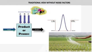
- 4. QUALITY: TRADITIONAL VS TAGUCHI’S VIEW o Traditionally, “Quality” is when the process output is within Customer Specifications. o Hence, NO QUALITY LOSS is there, if product is within the specifications. o As per Taguchi, “Quality” is when the process output is at the Target. o Every time, Process mean deviates from Target and there is process variance, there are bound to be quality losses. o Larger the deviation of mean from the target, larger is the loss. 4
- 5. 5 TRADITIONAL VIEW WITHOUT NOISE FACTORS
- 6. 6 TRADITIONAL VIEW WITH NOISE FACTORS
- 7. 7 TAGUCHI’S VIEW WITH NOISE FACTORS
- 8. Taguchi says that every time a process moves away from the Target, there is loss to customer. (even if the process is within SPECs) Taguchi recognizes the customer’s need to have products that are more consistent and part to part. This method gives a robust design in which the Process Y will not only stay within the specifications but also be centered always at the Target (= Mean). This is achieved by modeling not just the Controllable factors as in conventional DOE but also the “Noise” factors. TAGUCHI’S METHOD 8
- 9. 9 Taguchi’s designs can be adopted when: • Time and cost of experimentation has to be lowered, especially when we have large number of factors • In cases, where the number of CONTROL FACTORS > NUMBER OF NOISE FACTORS [Better chance of finding a factor that helps reduce the noise] • The product/ process under design is extremely critical. In no condition shall the process deviate from the target. • When the design objective is not just to attain the nominal best for the Response but is to attain best relationship between the output response and an input Signal factor. WHEN TO USE TAGUCHI METHODOLOGY ?
- 10. TAGUCHI’S LOSS FUNCTION o According to Taguchi (Japanese Engineer), every time the process deviates from the target, even if it stays within the SPECs, there is loss to the society (Producer and Customer) o Larger the deviation from the target, larger is the loss o Loss is proportional to the square of the deviation from the target o Loss caused by harmful side effects or variability. o Taguchi’s (quality) Loss function is given as, 10 Loss (y) = 𝑘 𝑦 − 𝑚 2 Ex: CARs being called back due to minor errors
- 11. Loss (y) = 𝑘 𝑦 − 𝑚 2 Where, k = A / 𝑑2 And A = the cost of corrective action necessary to change the process d = the value of the process m = the target value of the process characteristic y = the measurement of the unit in question k = the loss coefficient Loss (y) = the incremental loss This function drives the OBJECTIVE of the Taguchi’s design, which is to design a process that not just complies to the Customer specifications BUT also is aligned to the TARGET. 11 Example: When an automobile doesn’t start in cold weather, its owner faces loss. 1. Pay someone. 2. Late for Work. 3. Suffers Cold. TAGUCHI’S LOSS FUNCTION Loss (y) = 𝑘 𝑦 − 𝑚 2
- 12. 12 SIGNAL TO NOISE RATIO • Product with this goal (higher S / N Ratio) will deliver more consistent performance even in extreme conditions. : Standard deviation or natural variance : Mean / Average • Control factors (Signals) are those design and process parameters that can be controlled. • Noise factors cannot be controlled during production of product; controlled during expt. • To get the desired result (Higher S / N Ratio): • Identify optimal control factors that not only increase the QUALITY but also reduce NOISE.
- 13. 13 VARIATION OF THE QUADRATIC LOSS FUNCTION Ex. Colour Density and Brightness must be Optimum. Power output.
- 14. 14 VARIATION OF THE QUADRATIC LOSS FUNCTION Ex. Radiation leakage in Microwave Oven; pollution; leakage current.
- 15. 15 VARIATION OF THE QUADRATIC LOSS FUNCTION Ex. Bond strength of Adhesives.
- 16. 16 CASE STUDY: Tool Wear in a Process • Goalpost philosophy allows tool wear to produce parts which vary within specification limit. • This case study shows a cost-oriented approach to quality control. • We are required to make a Part of specific dimension with a tolerance of +-0.25mm • If the part reaches the end of the manufacturing line with diameter exceeding the upper or lower limit, the part should be scrapped at $4.00. • The scrap cost is one aspect of loss to society.
- 17. 17 Loss (y) = 𝑘 𝑦 − 𝑚 2 L is the loss associated with a diameter value y, m is the nominal value of specification, and value of k is a constant depending upon the cost at the specification limits and the width of specification. CASE STUDY: Tool Wear in a Process
- 18. 18 $4.00 = k 𝐿𝑆𝐿 – 𝑚 2 The lower specification limit (LSL) is substituted into equation, which is where the $4.00 loss is incurred. The upper specification limit also could be used for this calculation. Solving for k, 𝑘 = $4.00 𝐿𝑆𝐿 – 𝑚 2 𝑘 = $4.00 −0.010 – 0.0 2 k = $40,000 per sq in. L = 40,000 𝑦 − 0.0 2 CASE STUDY: Tool Wear in a Process
- 19. 19 Now the loss associated with any part can be computed depending on the value of its diameter. For instance, a part with diameter of + 0.003 in (+ 0.08 mm) costs L = 40,000 0.003 − 0.0 2 L = $ 0.36 This is the loss per unit for each part shipped with an outer diameter of +0.003 in. Similarly for a part diameter of -0.002 in which are 11 quantities in number the cost incurred would be, L ( - 0.002 ) = $ 40,000 −0.002 − 0.0 2 = $ 0.16 x 11 = $1.76 CASE STUDY: Tool Wear in a Process
- 20. 20 CASE STUDY: Tool Wear in a Process
- 21. 21 THE DOE (DESIGN OF EXPERIMENTS PROCESS) EIGHT-STEPS IN TAGUCHI METHODOLOGY 1. Identify the main function, side effects and failure mode. 2. Identify the noise factor, testing condition and quality characteristics. 3. Identify the objective function to be optimized.(Brainstorming/Flowcharting/Ishikawa Fish-Bone Analysis) 4. Identify the control factor and their levels. 5. Select the Orthogonal Array, Matrix experiments. 6. Conduct the Matrix equipment. 7. Analyze the data; predict the optimum levels and performance. 8. Perform the verification experiment and plan the failure action. Ex. Aluminium Casting
- 22. 22 ORTHOGONAL ARRAYS Taguchi’s design uses Orthogonal arrays to reach the optimum solution with minimum trials at minimum cost. Orthogonality is represented as: ∑ xi . yj = 0, for all the pair of levels, where i, j represent high & low (+1, -1) levels. Advantage of this orthogonality is that each factor can be evaluated independently, without influence from others i.e. Factors do not effect each other during estimation.
- 23. 23 Control factors Responses Wire Materi al Diameter Length At Temp-1 At Temp-2 Cu[1] 5[1] 200 [1] 101.5 107.9 Cu[1] 5[1] 500 [-1] 100.8 102.1 Cu[1] 10[-1] 200 [1] 99.7 104.6 Cu[1] 10[-1] 500 [-1] 98.4 101.7 Al [-1] 5[1] 200 [1] 104.5 108.9 Al [-1] 5[1] 500 [-1] 105.4 110.6 Al [-1] 10[-1] 200 [1] 103.2 108.3 Al [-1] 10[-1] 500 [-1] 107.4 111.1 23 ORTHOGONAL ARRAYS: EXAMPLE Heating of a wire when electric current is passed through it: Factor-1: Wire diameter (1: 5 mm, -1-: 0 mm) Factor-2: Wire length (1: 200 mm, -1: 500 mm) Factor-3: Wire Material (1: Cu, -1: l) Noise: Ambient Temperature (1: 50C, -1: 350C) Orthogonal Arrays are used to represent the controllable factors and noise factors in a Robust design Controllable factors, with their levels, form the Inner array These factors are the design parameters in the selected process design concept Optimum levels for these factors are to be achieved which will maximize the Response and minimize the effect of Noise factors. The Noise factors form the Outer array These factors influence the Response (Output) but are not controlled during the use of the product Noise factors are forced to vary & based on the optimum response values, the optimal control factor settings are identified. Such optimal settings make the product/ process resistant to noise factor variance
- 24. Taguchi represents an Orthogonal Array as: where, S = number of levels for each factor k = maximum number of factors whose effects can be estimated without any interaction N = total number of trials during experimentation 2424 TAGUCHI’SNOTATION FOR ANORTHOGONALARRAY
- 26. 26 23 Factorial Design ORTHOGONAL ARRAYS: EXAMPLE 24 Factorial Design
- 28. 28 ORTHOGONAL ARRAYS: CASE STUDY II Consider a process, of producing steel springs, is generating considerable scrap due to cracking after heat treatment. A study is planned to determine better operating conditions to reduce the cracking problem. There are several ways to measure cracking - Size of the crack - Presence or absence of cracks The response selected was Y: the percentage without cracks in a batch of 100 springs Three major factors were believed to affect the response - T: Steel temperature before quenching - C: carbon content (percent) - O: Oil quenching temperature
- 29. 29 Problem: How general is this conclusion? Does it depend upon? - Quench Temperature? - Carbon Content? - Steel chemistry? - Spring type? Factorial Approach: - Include all factors in a balanced design: - To increase the generality of the conclusions, use a design that involves all eight combinations of the three factors. ORTHOGONAL ARRAYS: CASE STUDY II
- 30. 30 ORTHOGONAL ARRAYS: CASE STUDY II INTERACTING COLUMNS OF THE ORTHOGONAL ARRAY The above eight runs constitute a FULL FACTORIAL DESIGN. The design is balanced for every factor. This means 4 runs have T at 1450 and 4 have T at 1600. Same is true for C and O.
- 31. 31 ORTHOGONAL ARRAYS: CASE STUDY II AFTER ALL THE 8 EXPERIMENTS FOLLOWING DATA WAS OBTAINED THE RESPONSES WERE STUDIED, THE RESULT INDICATED - C has little effect - There is an interaction between T and O. - WHEN, Y: the number of cracks are minimum
- 32. 32 EFFICIENT TEST STRATERGIES •Full factorial designs •A full factorial design is a design in which researchers measure responses at all combinations of the factor levels. •2-level full factorial designs that contain only 2-level factors. •The number of runs necessary for a 2-level full factorial design is 2k where k is the number of factors. As the number of factors in a 2-level factorial design increases, the number of runs necessary to do a full factorial design increases quickly. For example, •A 2-level full factorial design with 6 factors requires 64 runs; a design with 9 factors requires 512 runs.
- 33. 33 •Fractional factorial designs •A fractional design is a design in which experimenters conduct only a selected subset or "fraction" of the runs in the full factorial design. Fractional factorial designs are a good choice when resources are limited or the number of factors in the design is large because they use fewer runs than the full factorial designs. •A fractional factorial design uses a subset of a full factorial design, so some of the main effects and 2-way interactions are confounded and cannot be separated from the effects of other higher-order interactions. Usually experimenters are willing to assume the higher- order effects are negligible in order to achieve information about main effects and low-order interactions with fewer runs. • Instead of varying one factor at a time, here multiple factors are varied to find the effect of one on another. EFFICIENT TEST STRATERGIES
- 34. 34 EFFICIENT TEST STRATERGIES A factorial design is type of designed experiment that lets you study of the effects that several factors can have on a response. When conducting an experiment, varying the levels of all factors at the same time instead of one at a time lets you study the interactions between the factors.
- 35. 35 REFERENCES 1. Phillip J. Ross, “Taguchi Techniques for Quality Engineering”, Tata McGraw-Hill Publishing Company, 2005. 2. Douglas C. Montgomery, “Design and Analysis of Experiments”, Wiley Publications, 2001. 3. Park, Sung H, “Robust Design and Analysis for Quality Engineering”, Chapman & Hall, London, 1996. 4. Bagchi, Tapan P, “Taguchi Methods Explained: Practical Steps to Robust Design”, Prentice Hall of India, New Delhi, 1993. 5. Madhav. S. Phadke, “Quality Engineering Using Robust Design”, Prentice Hall / AT&T, New jersey, USA, 1989.
- 36. Thank you !!! 36