SlideShare a Scribd company logo
© Confederation of Indian Industry
Process Optimization-Pyrosection
© Confederation of Indian Industry
Contents
 About Preheater system
 Pressure drop and velocity profile across Preheater
 Challenges in Pyrosection
 Concept of minimum air combustion
 Concept of excess of air
 Heat loss due to CO
 Importance of recuperation air
 Impact of secondary air on Flame
 Burner pipe centering methodology
 Challenges in cooler operation
© Confederation of Indian Industry
Contents
 Cooler efficiency calculations
 Energy balance across cooler
 Cooler efficiency curve
 Function of MFR (Cross Bar)
 Conada Effect in IKN
 CFD Study
 Thermal efficiency Calculations
 Low NOx burners
 Latest development in cyclones
© Confederation of Indian Industry
Contents
 Raw mix & Importance of liquid phase
 Kiln challenges during petcoke operation
 Important Case Studies
 Thumb rules
 Key points
© Confederation of Indian Industry
Preheater Systems
 Reduction of losses in Preheater system
 No of stages – By design
 Operation of Preheater – Air infiltration
 Number of stages
 4 stages – 725 kcal/kg
 5 stages – 700 kcal/kg
 6 stages – 685 kcal/kg
© Confederation of Indian Industry
Beauty of PH system ..
 PH – Basically meant for Heat Recovery
 80% in Ducts
 20% in Cyclones
 Why not have a long duct & 1 Cyclone ?
© Confederation of Indian Industry
 PH System – Heat Recovery
 Co-current – Ducts
 Counter Current – Cyclones (Little !!)
 Key Attributes
 Overall – Counter current
 Stage wise – Co-current
 Material to next stage – Encounters higher
temperature air !!
Beauty of PH system ..
© Confederation of Indian Industry
Pre-heaters
 Latest pre-heaters are designed with high efficiency low
pressure drop cyclones and efficient heat transfer
 Minimum observed pressure drop in PH tower
 470 mmwg for 6 stage pre-heater
 Best observed top stage cyclone efficiency-97%
 Lowest observed pre-heater exit temperature- 245 0C
 Minimum observed false air in pre-heater- 5%
© Confederation of Indian Industry
Pressure drop & Velocity profile Across Preheater
O2-5%
1
2
3
4
PH FAN 5
6
Calcine
r
kiln
Kiln Feed
O2-2.5%
Fan Inlet
pressure-500
mmwg
Temp-923 degree
C
-161 mmwg-6th
Temp-650 degree
C
-323 mmwg-4th
Temp-416
degree C
-373 mmwg-2nd
Temp-794
degree C
-221 mmwg-5th
Temp-418 degree C
-365 mmwg-3rd
Temp-259 degree C
-457 mmwg-Top
Duct velocity-17 m/s
© Confederation of Indian Industry
How to Calculate pressure Drop across preheater?
 Pressure drop across 6th stage-5th Stage
= (-161)-(-221)
= 60 mmwg
 Similarly for other cyclones
 6th -5th=60 mmwg
 5th-4th =102 mmwg
 4th-3rd = 42 mmwg
 3rd -2nd = 8mmwg…………………
 2nd-1st=84 mmwg
 Total pressure drop=296 mmwg+161=457 mmwg
 Acceptable pressure drop across latest cyclones=50-60 mmwg
Some thing wrong-
No heat transfer
Temp-418 degree C
-365 mmwg-3rd
Temp-416 degree C
-373 mmwg-2nd
To be
corrected
by CFD
Study
© Confederation of Indian Industry
How much saving by reducing pressure drop across
Preheater?
 Fan inlet Pressure = -530 mmwg
 Fan outlet = -45 mmwg
 Electrical power = 1500 kW
Reduction in Pressure drop = 50 mmwg
Saving = 50 X1500
(-45)-(-530)
= 154 kW
Therefore, checking the pressure profiling across the preheater
is very important activity.
© Confederation of Indian Industry
Velocity Profile Across Pyro section
 Riser Duct:-80% heat transfer takes place
 15-17 m/sec
 Down comer duct
 15-17 m/s
 TAD duct
 25 m/s
 Hood & cooler grate
 5 m/s
 Under cooler bull nose
 15 m/s
 Burning zone-9.5 m/s
© Confederation of Indian Industry
 High Pre-heater fan power consumption
 High Pre-heater cyclones pressure drop
 High specific fuel consumption
 High Cooler loss
 Difference in Clinker Quality
FEW MAJOR PROBLEMS IN PYRO PROCESS
© Confederation of Indian Industry
PROBLEMS IN PYRO PROCESS
1. High Pre-heater fan power consumption
Reasons :-
 Low Fan efficiency
 High pre-heater pressure drop
 High dust recirculation
 High False entry (excess air)
© Confederation of Indian Industry
PROBLEMS IN PYRO PROCESS
2. High Pre-heater Cyclone Pressure drop
Reasons :-
 Basic design
 Coating or material accumulation
 High velocity or flow
 Cyclone Erection made to suit at site
 Improper gas distribution
© Confederation of Indian Industry
PROBLEMS IN PYRO PROCESS
3. High Specific fuel consumption
Reasons :-
 Change in quality of fuel
 Low Cooler efficiency
 Low heat recuperation
4. High Cooler loss
Reasons :-
 Low heat recuperation
© Confederation of Indian Industry
Parameters Affecting SEC of PH fan
 Pressure drop across preheater of Fan
 Depend upon no of stages
 Best observed value 470 mmwg for 6 stage
 Fan efficiency
 Fan design and operating parameters
 Losses in speed Control
• VFD : 98% efficiency
• SPRS : 95% efficiency
• GRR : 90% efficiency
Lowest observed SEC of PH fan : 3.81 kWh/MT clk
© Confederation of Indian Industry
 Typical pressure drops - Latest PH with PC
4 Stage – 310 to 360 mmwg
5 Stage – 350 to 400 mmwg
6 Stage – 450 mmwg
Low Pressure Drop Cyclones
© Confederation of Indian Industry
Heat Losses in Pre-heater exit gas
Factor affecting the Heat loss in PH exit gas
PH EXIT GAS VOLUME- Depends upon the gas temp. &
false air infiltration
• Best observed value : 1.37 Nm3/kg clinker
PH EXIT GAS TEMP.- Depends upon the PH heat transfer
efficiency
• Best observed value : 245 0C
Lowest observed heat loss in PH exit gas : 120 kcal/kg clk
© Confederation of Indian Industry
How to calculate minimum air for
combustion?
 Lmin = 1.293 X (32/12 x % C + 16/2 x %H -% O +%S + 32/14 x %N)
1.429 x 21
Lmin = Kg air/kg Fuel
How to convert Kg air/kg fuel into Nm3/kg fuel?
Dividing by 1.29 kg/Nm3
Sample calculation:-
C-85.8%
Hydrogen-11%
Oxygen:-0.4%
Nitrogen:-0.8%
Sulphur:-2%
© Confederation of Indian Industry
How to calculate minimum air for
combustion?
 Lmin = 1.293 X (32/12 x 85.8 + 16/2 x 11 -0.4+2+ 32/14 x 0.8)
1.429 x21
Lmin = Kg air/kg Fuel
= 13.76 kg air/kg fuel
Nm3/fuel = 13.76/1.29
= 10.66 Nm3/kg fuel
© Confederation of Indian Industry
Lmin Values for different types of Coal(kg/1000 kcal)
Lignite :- 1.388
Bituminous :- 1.398
Anthracite :- 1.412
Petcoke : 1.407
Diesel : 1.408
Lmin Flow = Lmin x Heat consumption x Production per dayx1000
24 x 1000
Heat Consumption = kcal/kg clinker
Production = TPD
Lmin Flow = kg/hr
© Confederation of Indian Industry
Excess Air Concept
 Air requirement for complete combustion process across the
pyro section is 10 percent of Lmin .
For example :-Pet coke
Air Requirement = 1.10 X 1.407
= 1.54 kg air/1000 kcal
For anthracite coal:-
= 1.41x1.10
= 1.55
Note:-But generally due to Sulphur dilution ,the amount of excess
air is increased in the case of pet coke.
© Confederation of Indian Industry
Excess Air Concept
© Confederation of Indian Industry
Standard Values
 Kiln Inlet :- 2% O2
 Calciner Outlet :- 2% O2
 Preheater outlet :- 3-4% O2
 Preheater Flow :- 1.30-1.50 Nm3/kg Clinker in case of normal coal
:- 1.45-1.55 Nm3/kg clinker in case of pet coke
Recuperation Air :- 0.75 Nm3/kg Clinker for normal coal
:- 0.80 Nm3/kg Clinker for pet coke
© Confederation of Indian Industry
Excess Air Calculation
 How to find excess air?(approximate & when CO formation is min)
= O2 percentage X 100
21 –O2 percentage
= (5/21-5) x100
= 31.25%
Oxygen :-2% at kiln inlet –Find excess air?
= (2/21-2) X100
= 10.52%
© Confederation of Indian Industry
Heat loss due to excess Air
© Confederation of Indian Industry
Numerical No1
Heat Loss due to excess Air
 Preheater gas flow = 1.30 Nm3/kg clinker
 Excess air = 10%
 Then Volume:
= 1.10 x 1.30
= 1.43 Nm3/kg clinker
= 1.43-1.30
= 0.13 Nm3/kg clinker
Preheater gas temp-250 degree C
= 0.13x1.42x0.23x250
= 10.60 kcal/kg clinker loss
© Confederation of Indian Industry
Heat loss due to CO formation?
C + O2 – CO2 + 8084 kCals/kg of Carbon
2C + O2 – 2 CO + 2430 kCals/kg of Carbon
2H2 + O2 – 2H2O + 28,922 kCals/kg of Hydrogen
S + O2 - SO2 + 2,224 kCals/kg of Sulphur
 Each kilogram of CO formed means a loss of 5654 kCal of
heat (8084 – 2430)
© Confederation of Indian Industry
Importance of Recuperation Air
 Recuperation Air:-Secondary Air + Tertiary Air
 Secondary Air:-
 It is the main part of the combustion air (85 – 95% of total
air fed).
 Flame direction is usually affected by the buoyancy of
secondary air.
 Lower temperature of secondary air causes increase in
velocity of secondary air as a consequent the mixing of
air with coal is in efficient which makes the lengthy flame.
© Confederation of Indian Industry
Which is the correct flame?
Flame no1
Flame No2
Flame No3
© Confederation of Indian Industry
Which is the correct flame?
Flame no1
Long Flame, unstable coating, high back end
temp, low shell temperature
Short Intense divergent flame, low back end
temp, high shell temperature, poor refractory
life, good for burning
Flame no2
Flame no3
Convergent flame, low shell temperature,
good refractory life, good for burning, stable
coating.
Flame no3 is the correct one
© Confederation of Indian Industry
Effect of Secondary Air on Flame
© Confederation of Indian Industry
Impact of Secondary Air velocity on flame length
 Higher the secondary Velocity
longer is the flame, hence to
increase the flame momentum by
increasing primary air velocity at the
burner tip as a result the overall
heat consumption would be
increased.
© Confederation of Indian Industry
Impact of Secondary Air velocity on
flame length
Q = A XV
Q is directly proportional to V as a result Q will be increased
and finally affects the heat consumption
 Higher secondary air velocity that causes the lower the hot
air pressure region, therefore, we have to increase the
pressure drop at the tip to pull back more secondary air
towards the flame.
 Secondary Air Velocity:-5-6 m/s
© Confederation of Indian Industry
Burner Pipe Centering
 Position 7,4,1,2& 3 are away from
material inside the kiln.
 Position 9 & 8 are very close to the
charge.
 Only 5 is close to the material as well
as with refractory & this position is best
because it gives the uniform thermal
distribution .
© Confederation of Indian Industry
Burner Pipe Centering
 Why we are not considering 7,4,1,2,&3 position?
 These positions are very close to the refractory and it can
damage the refractory through burning.
 some times flame is disturbed
 Position 8 & 9 is Very close to the material
 if coal is trapped it has serious negative impact.
© Confederation of Indian Industry
Impact of Primary Air on Fuel Consumption
© Confederation of Indian Industry
Challenges in Cooler Operation
 Snowmen formation
 Red river
 Low Efficiency of Cooler
Reason for Snowmen:-
 Dusty operation of the kiln
 Fine particles formation
 Cooling air face more resistance in case of fine particle
 Kiln overheated
 Melting condition inside the kiln
 Change in burner pipe position which affects the cooling zone
inside the kiln
 Raw mix design
© Confederation of Indian Industry
Challenges in Cooler Operation
Reason for red river:-
 Fine dusty clinker
 Segregation in kiln due to wide range in particle size.
 Material characteristics , and rotation of kiln
 Cooler design, air flow distribution Non-uniform
clinker bed
 Operation and maintenance of cooler
© Confederation of Indian Industry
Cooler Efficiency curve
© Confederation of Indian Industry
Cooling Air resistance
© Confederation of Indian Industry
Effect of resistance grates
© Confederation of Indian Industry
Cooler Efficiency trends
(conventional to 3rd generation)
© Confederation of Indian Industry
Cooler Efficiency Calculations
Calculate total input air in kg air /kg clinker.
 Total Input air= Cooler Vent Air + Recuperation Air(all value on
mass basis)
ESP
Cooler vent Air Recuperation air
© Confederation of Indian Industry
Energy Balance of Cooler
4
COOLER
Input
heat
from
clinker Input heat
from
cooling air
Heat
losses
from
clinker
SA+TA
Cooler Vent
Air
Radiation &
Convection
losses
© Confederation of Indian Industry
Cooler Efficiency Calculations
Input Heat from clinker = 0.2733 x(Inlet Clinker Temp-Refrence T )
Inlet Clinker temp = 1400 degree C
Input heat from clinker = 382.6 kcal/kg clinker
Input heat Cooling air = 17.9 kcal/kg clinker(ABC plant)
Total input Heat = 400.5 kcal/kg clinker--------
Heat Output
Heat through Vent Air = 92.2 kcal/kg clinker----------1
Heat through clinker = 26.9 kcal/kg clinker----------2
Radiation & Convection = 5 kcal/kg clinker---------------3
Heat through Water Spra = 37.7 kcal/kg clinker…………4
© Confederation of Indian Industry
Importance of cooler Efficiency
Heat through Secondary & TA = Input Heat-(1+2+3+4)
= 400.5-161.80
= 239 kcal/kg clinker
Cooler recuperation efficiency
= Heat through Secondary & tertiary Air x 100
Input heat from cooler
= 60 %
© Confederation of Indian Industry
Important Facts-Cooler
 The hotter the inlet temperature the hotter the
clinker outlet temperature.
 The hotter the cooling air temperature the hotter the
clinker outlet temperature.
 The longer the air/material contact time the cooler
the clinker outlet temperature.
© Confederation of Indian Industry
Latest Generation of Coolers
 FLS SF cross bar cooler
 IKN pendulum cooler
 Claudius Peters ETA (ɳ)cooler
 CemProTec Revolving Disc Cooler (RDC)
© Confederation of Indian Industry
Major Developments
SF Cross Bar Cooler- The 4 Innovative features:
 Fixed grate line for air distribution
 Conveying system separate from Cooling
system
 Grate plates with individual regulators for
cooling air-Cooling Techniques – Unique
 Modular design
© Confederation of Indian Industry
Mechanical Flow Regulation (MFR)
 Classical compartment
aeration
 Each plate equipped with
a mechanical flow
regulator
 Pressure drop across
perforated plate controls
regulator opening
 Gives constant flow
independently of clinker
resistance
 Eliminates need for air
beam
© Confederation of Indian Industry
Operation of the (MFR)
© Confederation of Indian Industry
Effect of resistance grates
© Confederation of Indian Industry
Working of MFR
© Confederation of Indian Industry
11/26/2020
Case Study of Cooler Upgrade with Cross Bar
Cooler
Parameter Unit Before After
Production TPD 3150 3400
Cooler loss Kcal/ Kg Cl 135 98
SPC kWh/MT 5.7 5.17*
Clinker
temp
Deg C 195 98
•Power includes Cooler Fans, cooler drives & HRB
© Confederation of Indian Industry
Hot Air Recirculation
+20-25%
More heat
Waste Heat Recovery Maximised
without compromising Recuperation Efficiency
© Confederation of Indian Industry
Waste Heat Recovery with hot air recirculation
Mid air / WHR
Vent air
Secondary +
Tertiary air
© Confederation of Indian Industry
IKN Pendulum Cooler
 Pendulum cooler – IKN
 Unique features
 Stationary inlet
 Coanda nozzle
 Oscillating frames
© Confederation of Indian Industry
Coanda Nozzles
 Narrow, inclined and curved slots in
transport direction of clinker
 Narrow sharp jet of air – 40 m/sec
(Horizontal)
 Fines are swept to the clinker bed
surface, Coanda nozzles are completely
engulfed by the cooling air
 Fines always on top – Fluidized
 Coarser pushed mechanically at the
bottom
 No Red river problem
© Confederation of Indian Industry
Oscillating Frames
© Confederation of Indian Industry
Features of IKN Cooler
 Low Air requirement
 Specific power consumption
< 4 units/ton
 Lower clinker temperatures
< 100C
© Confederation of Indian Industry
Operating results before and after the IKN
upgrade
Before After
Production rate (TPD) 5550 5750
TA Temp (oC) 760 930
Sp. Heat Consumption
(kcal/kg clk)
710 690
Power in cooler section
(kW/MT clk)
4.47 3.88
Cooler vent air temp (oC) 220 200
Clinker temp (oC) 152 132
© Confederation of Indian Industry
Revolving Disc Cooler (RDC)- 5th Generation
Cooler
© Confederation of Indian Industry
 Introduced by CemProTec, Germany
 Operates according to the “revolving disc” principle
 The travelling grate is replaced by revolving disc
 Under trial, results are being awaited
Revolving Disc Cooler (RDC)- 5th Generation
Cooler
© Confederation of Indian Industry
 Revolving disc – speed 30 min per round
 High efficiency- 100% cross flow heat exchange
 Low cooling air volume and hence exhaust air
 No clinker spillage- Dust handling & transport
system not required
 100% transport efficiency
 Very limited wear & maintenance
Revolving Disc Cooler (RDC)- 5th Generation
Cooler
© Confederation of Indian Industry
Benefits of Latest Generation High efficiency
cooler
 Better clinker properties
 Lower exit gas and clinker temperature
 Lower cooling air requirement
 Total heat loss of latest generation cooler is less than 110
kcal/kg clk
 Recuperation efficiency 75-80%
 Retrofitting of existing conventional cooler with latest
generation cooler offers significant potential for electrical and
thermal energy saving
© Confederation of Indian Industry
Cooler Vent Fan
 Typical power consumption
 0.5 to 1.0 kW/ton
 Typical pressure drops required
 40 – 50 mmWC
 Fan design (Head) very important
 Natural draught available
Example 220C, 55 m height
© Confederation of Indian Industry
Cooler vent fan
PARAMETERS AFFECTING THE SEC OF COOLER VENT FAN
 PRESSURE AT FAN INLET- Depends upon the pressure drop in
cooler ESP and duct
• Best observed value : 40 mmWc
 EFFICIENCY OF FAN- Depends upon the fan design and operating
parameters
 CHIMNEY EFFECT- Depends upon the chimney height & dia.
 LOSSES IN SPEED CONTROL- Depends upon the type of control
installed
Lowest observed SEC of Cooler vent fan : 0.13 kWh/MT clk
© Confederation of Indian Industry
How to choose best cooler System?
 Minimum specific power consumption of cooler fans and
vent fan
 Cooler fans:-3-3.5 kWh/ton clinker
 ESP Fans:-0.5-1.0 kWh/ton of clinker
 Cooler recuperation efficiency should be greater than 70 %
 Cooler Efficiency:-70-77%
 Total losses:-110 kcal/kg clinker
 (Cooler Vent + Radiation+Clinker)
 Should be good in terms of maintenance point of view also
© Confederation of Indian Industry
Numerical No
N1:-A grate cooler with cooler recuperation efficiency of 44% is
to be replaced with high efficient cooler of 77% efficiency then
calculate the benefit in terms of kcal/kg clinker?
Also estimate the benefit in vent losses
Present SEC-760 Kcal/kg clinker
© Confederation of Indian Industry
CFD Study & Thermal Efficiency
Calculations
© Confederation of Indian Industry
Application of CFD to Improve Efficiency
 Computational Fluid Dynamics (CFD)
• Predicting the fluid flow related problem by
solving mathematically, the equations which
govern the process.
• Numerical calculation method for solving
fluid flow problems as possible, in solving
practical engineering flow, heat transfer
problem
© Confederation of Indian Industry
CFD – Application Areas
Cyclone Ducts
Electrostatic
Precipitators (ESP)
Baghouse
Raw Mill/ Coal Mill Kiln/ Calciner
Gas Conditioning
Tower
© Confederation of Indian Industry
Application of CFD to Improve Efficiency
 CFD study identifies the region offering high
pressure drop, improper flow distribution, high
velocity region etc.
 Benefits of CFD study:
Reducing the high pressure drop in pre-heater
cyclones
Reducing the high pressure drop in ducts
Improving the cyclone efficiency
© Confederation of Indian Industry
Reasons for High PH Exit
Temperature are
 Improper material distribution
 High velocity
 High excess air
 High return dust (low cyclone
efficiency)
Heat Transfer Analysis in Riser Duct for Flue gas with
Particles elaborates the Temperature
Thermal Efficiency Improvement in PH System
© Confederation of Indian Industry
By CFD analysis, the Exit Temperature Can Reduce &
Reduction in Heat consumption about 5-20 kcal / kg clinker is
possible.
By means of
 Modification in Riser Duct
 Modification in Spreader Box & Feed Pipe
 Modification in Cyclones
Thermal Efficiency Improvement in PH System
© Confederation of Indian Industry
Velocity Distribution
in Calciner
 Benefits by CFD analysis in the Cal
 Improvement in coal particle
distribution
 Improvement in flow
Distribution of Velocities
which improves the combustion
 Reduces the high concentration
of Temperature near the wall.
 Improvement in residual time
of the Particle
 Overall improvement in
calcinations
Particle Trajectory
in Calciner
Thermal Efficiency Improvement in Calciner
© Confederation of Indian Industry
Cyclone Performance Analysis
Pre-modified duct
© Confederation of Indian Industry
CFD Analysis PH system
Streamlines plot at the inlet duct of III stage cyclone
Reduction in Pressure drop up to
20mm WC
© Confederation of Indian Industry
CFD Analysis for PH system
Project Completed and analysis report shows pressure drop up to 25mm WC
© Confederation of Indian Industry
Pre-modified Cyclone analysis
with duct
Modified Cyclone analysis with
duct
Cyclone Performance Analysis
Reduced pressure drop by
60 mm WC(10%
reduction in Fan Power).
Energy savings 50 KW/h.
Payback period less than
4 months.
© Confederation of Indian Industry
Dust loss from Pre-heater system/Improvement of
Cyclone Efficiency By CFD study
PH & PC
Feed 300 tph
75°C
Dust loss – 30 tph
275°C
 Top cyclone eff
 Design – 96 %
 Actual – 90 %
 Equivalent heat loss
– 10 kcal /kg
© Confederation of Indian Industry
Dust loss from Pre-heater system / Improvement of Cyclone
Efficiency By CFD study
 Pre-heater dust loss – 10 %
 Dust goes out at about 275ºC
 Fresh feed enters at 75ºC
 Material heat loss alone – 10.0 kcal/kg
 Top cyclone efficiency increase of 3 % means -3.0
kcal/kg
© Confederation of Indian Industry
Dust loss from Pre-heater system / Improvement of
Cyclone Efficiency By CFD study
 Excellent opportunity
 CII had discussions with consultants on reducing dust
loss thro CFD analysis & retrofit
 Consultant positive on dust loss reduction without
increasing pressure drop
 Has been successful in several Cement plants
© Confederation of Indian Industry
Improvement of Cyclone Efficiency By CFD study
Present Cyclone Efficiency = 90%
Design Efficiency = 96%
Kiln feed to clinker Factor = 1.6
Fresh Feed enters at temperature 75 degree C
Present dust loss = 0.10X1.60
= 0.16 kg material
Present heat loss = 0.16x0.23x275
= 10 kcal/kg clinker
© Confederation of Indian Industry
Improvement of Cyclone Efficiency By
CFD study
Recoverable is 3%
Improving in efficiency by CFD study(Considering 93%)
= 0.07*1.60
= 0.112
Benefit in dust loss = 0.16-0.112
= 0.048 kg material
Heat improvement = 0.048xspecific heat of flue
gasesxT
Q = 0.048x0.23x(275-0)
= 3.03 kcal/kg clinker
© Confederation of Indian Industry
Calculations
Thermal cost = RS 1100 Mkcal
(Million kilo calorie)
Clinker production :- 4500 ton/day;
NCV of coal = 7000 kcal/kg coal
Overall Heat saving per day
= 3x4500x1000
= 13.5 Mkcal per day
© Confederation of Indian Industry
13.5 Mkcal per day/
In terms of coal = 1.92 ton of coal in a day
No of days per annum = 300
= 13.5x300
= (4050) Mkcal
- Energy saving per annum
= 4050 x 1100
Savings = Rs 44.55 lakhs per annum
Investment = 20 lakhs
Payback = 20 X12
44.55
= 6 months
Calculations
© Confederation of Indian Industry
Dust loss from Pre-heater system/ Improvement of
Cyclone Efficiency By CFD study
 I Step
 Conducted CFD analysis for top cyclone
 Implement retrofits to improve efficiency
 Target efficiency - 93 %
 Improvement in efficiency – 3 kcal / kg clinker
Saving - Rs. 44.50 lakhs
Investment - Rs. 20 lakhs
Payback - 6 months
© Confederation of Indian Industry
Minimize Heat Loss in Tertiary Air Duct
Cooler
PC
950oC
840oC
Heat Loss
•Air infiltration in TA duct
•Surface Heat Loss
© Confederation of Indian Industry
TA Duct – Thermograph Images
© Confederation of Indian Industry
TA Duct – Thermograph Images
© Confederation of Indian Industry
Minimize heat loss in TA Duct
 Air infiltration
 Atmospheric air entry
 Reduces Air intake from Cooler
 Cooler vent – higher temperature
 Arresting air infiltration
 Lower ambient air ingress
 Increases cooler air utilization (at Temp of
about 500 Deg C)
© Confederation of Indian Industry
Minimize heat loss in TA duct
 Surface insulation
 Hot spots observed > 200 Deg C
 Significant drop between cooler & PC
 Radiation loss estimated > 5 kCal/kg Cl
 Loss due to air infiltration ~ 3 kCal/kg Cl
 TARGET – 30-40oC drop between cooler exit and PC
© Confederation of Indian Industry
Calculations
Present Temperature Drop:-
= 950-840
= 110 oC
Margin in temperature = 110-40
= 70 oC
Considering recuperation air = 0.80 Nm3/kg clinker
Total air requirement for calciner
= 0.60 x 0.80
= 0.48 Nm3/kg clinker
Mass = 0.48 x1.29
= 0.6192 kg air/kg clinker
= 0.6192 x 0.25x 70
= 10.836 kcal/kg clinker benefit
© Confederation of Indian Industry
Calculations
Thermal cost
= Rs 1100 Mkcal
(million kilo calorie)
Clinker production = Rs 4500 ton/day
NCV of coal = 7000 kcal/kg coal
Overall Heat saving per day
= 10.836x4500x1000
= 48.76 Mkcal per day/ In terms
of coal
= 6.96 ton of coal in a day
© Confederation of Indian Industry
Calculations
 No of days per annum:= 300
= 48.76x300
= (14628) Mkcal
Energy saving per annum
Annual Saving
= 14628 x 1100
= Rs 160.90 lakhs per annum
Investment = 70 lakhs
Payback = 70 X 12
160.96
= 6 months
© Confederation of Indian Industry
Minimize heat loss in TA duct
 Annual Saving - Rs 160.90 Lakhs
 Investment - Rs 70.0 Lakhs
 Payback period - 6 Months
© Confederation of Indian Industry
Reduce PH exit temperature
1 A 1 B
2
3
4
5
1 A 1 B
2
3
4
5
325 oC
293 oC
502 oC
659 oC
815 oC
893 oC
478 oC
650 oC
799 oC
890 oC
Standard profile
Case stufy plant profile
ILC
ILC
© Confederation of Indian Industry
Lower Dispersion Box in riser ducts and increase
heat transfer
 PH system – heat transfer
 Overall – Counter current
 Each Stage – Co-current
 Maximum heat transfer in riser ducts
 Separation of material & air in cyclones
 Very little heat transfer in cyclones
© Confederation of Indian Industry
Lower Dispersion Box in riser ducts and increase
heat transfer
 Latest approach
 Locate feed pipe as low as possible
 Increases heat transfer in riser ducts
 Lowers PH gas exit temperature
 Discussions with Suppliers & other Cement Plants
 Favor this step (Upto 1 m, easy)
 Implemented in several plants
© Confederation of Indian Industry
Present System
Kiln String Calciner String
Dispersion
Box Height
Total Riser
Height
Dispersion
Box Height
Total Riser
Height
5.055 16.932 2.953 14.570
3.0 12.8 2.947 12.392
5.435 12.78 3.335 13.2
2.1 12 3.053 12.918
4.435 13.4 4.7 -
© Confederation of Indian Industry
 Good potential to lower the feed point
 Discussion with supplier before implementation
 Saving of 10-15oC
 2.5 - 3 kCal / kg of clinker, At least
 Recommended to take up one by one
 Monitor temp & pressure profiles closely
Lower Dispersion Box in riser ducts and increase
heat transfer
© Confederation of Indian Industry
Lower Dispersion Box in riser ducts and increase
heat transfer
Annual Saving - Rs 34.98 Lakhs
Investment - Rs 6.0 Lakhs
Payback period - 2 Months
© Confederation of Indian Industry
Reduce cold air entry into system
 Cold air entry in Kiln and Pre-heater system
 Coal conveying
 Primary air
 Coal conveying offers a good potential for energy
saving
 Presently coal conveying air – ~ 16.0 tph
 Same irrespective of type of coal used
 Equivalent heat loss with air finally going out at
265°C is – 1.50 kcal/kg
© Confederation of Indian Industry
Reduce cold air entry into system..
 Phase density for FK pumps – up to 7 possible
 Present phase density – 2 to 2.5
 Varies depending on the coal used and the fineness
 Good potential to reduce
 Install VFD for all four coal conveying blowers
 Reduce rpm in a phased manner
 5 % steps and observe performance
 Target speed reduction – 20 - 25%
© Confederation of Indian Industry
Reduce cold air entry into system
Saving - Rs. 26.61 Lakhs
Investment - Rs. 30.0 lakhs
Payback - 14 months
© Confederation of Indian Industry
Impact of False Air on fuel & Electrical Consumption
O2-5%
1
2
3
4
PH FAN 5
6
Calcine
r
kiln
Kiln
Feed
O2-2.5%
Measuring Points
1) Calciner Outlet
2) Preheater down
Comer
3) Fan Inlet
Temp-275
degree C
Fan Inlet
pressure-600
mmwg
© Confederation of Indian Industry
Calculations
 Preheater Down Comer:-5%
 Calciner Outlet:-2.5%
Apply False Air Formula
= (Down Comer oxygen-Calciner outlet) X 100
( 21-calciner outlet oxygen)
= 5-2.5 X 100
21-2.5
= 13.5 %
Consider preheater outlet Temperature :- 275 degree C
Considering Reduction in false air :- 5%
Present Flow: - 1.50 Nm3/kg Clinker
© Confederation of Indian Industry
Impact of False Air on fuel Consumption
Mass Flow Rate = 1.50x1.42
= 2.13 kg gases /kg clinker
Reduction in mass flow by reducing
FA = 0.05x2.13
= 0.1065 kg/kg clinker
Heat Loss = 0.1065xspecific heat of flue
gasesxTemp difference
© Confederation of Indian Industry
Impact of False Air on fuel Consumption
Q = 0.1065x0.23x(275-0)
= 6.73 kcal/kg clinker.
Thermal cost = RS 1100 Mkcal
(million kilo calorie)
Clinker production:- = 4500 ton/day
NCV of Coal = 7000 kcal/kg coal
© Confederation of Indian Industry
Overall Heat loss per day
= 6.73x4500x1000
= 30285000 kcal per day
In terms of coal = 4.326 ton of coal in a day
No of days per annum: = 300
= 30285000x300
= (9,085) Mkcal
- energy saving per annum
In terms of Mkcal = (9.085x10^9)/(10^6)
= 9.085x(10^3 )
Cost = 9085 x 1100
Saving = Rs 99.93 lakhs per annum
Impact of False Air on fuel Consumption
© Confederation of Indian Industry
Impact of False Air on Electrical power
Electrical Loss = Percentage of false airX electrical
power of fan
Electrical power = 1400 kW
Power loss = 0.05x1400
= 70 kW
Electrical cost = Rs 5 kWh
No of days per annum: -300
Annual Saving = 135x300x5x24
= 25.2 lakhs per annum
Total Saving = 99.93+25.2
= 125 lakhs
© Confederation of Indian Industry
Impact of False Air on Electrical power
Saving - Rs. 125. Lakhs
Investment - Rs. 50.0 lakhs
Payback - 5 months
Pay back = (50/125)x12
= 5 months
© Confederation of Indian Industry
Burners
 The ultimate objective of a burner is to provide a
stable short and intense flame for burning of raw
materials to the desired temperature and achieve
heat economy
 More efficient mixing of fuel and air
 Improvement in entrainment of secondary air
© Confederation of Indian Industry
First Generation Burners(conventional)
Advantages
 Burning traditional Fuels
 Good Flame Adjustability
 Good Mixing of the combustion air with the Fuel
Disadvantages
 Generation of high Nitrogen oxides emissions
 Inability to use market dependent alternate fuels
© Confederation of Indian Industry
Second Generation burner(Multichannel)
Duoflex burner:-FLS
Pyrojet:-KHD
Pillard:-Rotaflam
Greco:-Greco
© Confederation of Indian Industry
How to select best burner for the plant operation?
 Adjustability of the flame shape to suit the kiln operation
and type of fuel
 Operating costs and servicing costs
Other Important process parameters
 Primary air requirement(%) & pressure(effect the energy cons.)
 Flame momentum
 Coal conveying air(solid loading ratio)
 NOX emissions (Low NOX burner)
Emission behavior with respect to NOx emissions
 Flexibility with traditional fuels
 Flexibility with market-dependent alternative fuels
© Confederation of Indian Industry
NOX Generation
 Thermal NOX
 Form in burning zone and reaction takes place at high
temperature(1400 degree C)
2N2+O2-2NO +N
N+O2-NO+O
 Higher excess air results high amount of NOX
 As Input N2 increases due to excess air
 High residence time in calciner also increase the NOX
formation
© Confederation of Indian Industry
NOX Generation
Fuel NOX
 Fuel NOx is formed by the oxidation of nitrogen present in
fuel
 A study has indicated that gas-fired, dry-process kilns
typically produce almost three times more NOx than coal-
fired, dry-process kilns
 Fuel NOx predominates NOx generation in the calciner and
at lower-temperature combustion sites.
 Approximately 60% of fuel nitrogen is converted to NOx and
is dependent upon available oxygen in the flame and
temperature profile
© Confederation of Indian Industry
Low NOx Burners
(Latest generation Burners)
Parameters FLS –Jet Flex Novaflam KHD Pyrojet
Type of Fuel
Coal or Pet
coke
Coal or Pet coke Coal or Pet coke
Transport Air volumetric
flow for pet coke
2805 m3/hr 2135 Nm3/hr 2165 Nm3/hr
Solid loading factor-coal 3.8 4.96 kg coal/Nm3 4.90 kg coal/Nm3
Primary air cons(%) 5-6% 6.5% 4.8%
Primary air pressure(mbar) 700 500 Jet-900;swirl-160
Primary air flow 5100 m3/hr. 5500 Nm3/hr
Jet-2710m3/hr;swirl:-
1355 m3/hr
Burner out put(68 MW)
Primary air consumption:-
8-9% in ordinary multichannel burner with low pressure(1500-2500 mmwg).
© Confederation of Indian Industry
Low NOx burner Concept
 Less primary air means less oxygen and may produce an
initial high-temperature, fuel-rich combustion zone,
followed by a low-temperature fuel-lean combustion zone.
Such a combination is likely to reduce the formation of
NOx.
 Reduce flame turbulence, delay fuel & air mixing and
establish fuel rich zones for initial combustion
 A fuel-rich, oxygen-lean, high temperature combustion
zone is created first by reducing the amount of primary air
in the primary combustion zone and delaying the
combustion of all of the fuel
© Confederation of Indian Industry
NOX reduction-solutions(Primary level)
 Reducing excess air levels also results in increased
productivity per unit of energy; thus, resulting in the indirect
reduction of NOx emissions per amount of clinker produced.
 Improving burnability of kiln feed & thermal efficiency of the
system
 Reduction in heat consumption
 Installing the low NOX burner
 Change in the preheater system(hot bottom formation in ILC)
 Nitrogen content in the fuel
 Latest developments by technology suppliers
© Confederation of Indian Industry
Case Study No1
Objective
Toreduce the primary air percentage by installing pillard Novaflame
burner
Primary air consumption:-12%
Problems:-
Frequent build up in the 28th m of the kiln
Benefits:-
After changing the burner the coating tendencies are reduced and
plant team are able to increase the petcoke to 100%.
© Confederation of Indian Industry
Case Study
Project Economics:-
Energy saving:-2 kcal per kg clinker
Total fuel saving:-350 tonnage of coal
Cost :-Rs 6500 per ton of coal
Total cost saving:-Rs 23 lakhs per annum
Investment:-Rs 52 lakhs
Payback:-27 months
© Confederation of Indian Industry
Case Study No2
 Pyro-Jet Burner was commissioned successfully and
Primary Air consumption reduced by 5% thereby Heat
consumption reduced by 5 Kcal/ kg clinker
© Confederation of Indian Industry
Latest Developments:-KHD Pyroclon-R Low NOx
© Confederation of Indian Industry
Fuel
PYROREDX Reactor
Main Calciner
①
②
Technology
 Gasifying reactor between
kiln and calciner.
 Formation of CO by
Boudouard reaction.
 Reduction of NOx.
 Suppression of fuel NOx
formation.
PYROCLON® Redox Reactor-For low NOX
© Confederation of Indian Industry
PYROCLON® Redox Reactor-For low NOX
© Confederation of Indian Industry
Redox reactor inlet Gas Composition:
CO2 19.4 Vol.%
CO 0 Vol.%
100 % Of Calciner Fuel fired in PYROREDOX duct in Kiln Flue gas only,
Without any TERTIARY Air admission hence Reducing atmosphere (
Insufficient Combustion air / Starved O2 Condition ) Created In
PYROREDOX.
Due to reducing atmospheres in PYROREDOX, the CO2 in kiln flue gas react
with fuel C which is sub stoichiometric conditions. The sub stoichiometric
reaction as follows and it produces CO at the same time CO2 content of
flue gas reduces to 8.1 % , hence Conversion of NO into N2 using CO is > 95
%
CO2 + C  2 CO
Boudouard reaction
Working Principle
© Confederation of Indian Industry
Working Principle
 Redox reactor outlet / Calciner Inlet Gas Composition:
 CO2 8.1 Vol.% `
 CO 21.8 Vol.%
 The above condition is very favorable for DENOX Reaction using CO
as Follows
 2CO + 2NO = 2CO2 + N2
 Final NOX CONCENTRATION IN CALCINER OUTLET IS < 500 mg/Nm3
@ 10 % O
© Confederation of Indian Industry
 Typical pressure drops - Latest PH with PC
 4 Stage – 310 to 360 mmwg
 5 Stage – 350 to 400 mmwg
 6 Stage – 450 mmwg
Low Pressure Drop Cyclones
© Confederation of Indian Industry
Latest development in Cyclones by KHD
Previous Cyclone
Design
55% dip tube ratio
Inlet cross section 100%
h/w = 1,6
High Efficiency (HE)
Cyclone
Design for > 60% dip
tube ratio
New 110%
h/w = 2,0
Benefits
Based on same capacity
 Dp saving of 1,5 - 2
mbar per cyclone
stage
 Smaller Cyclone size
can be used
 Less equipment and
building expenditure
© Confederation of Indian Industry
New design
6852 HE / 5
25,5 mbar 22,6 mbar
11,1 mbar 7,1 mbar
36,6 mbar 29,7 mbar
Cyclone Developments –CASE STUDY
Existing design
7950/5
Double Separator:
• increased by one size
System Cyclones:
• reduced by one size
• new design of gas inlet
• increased dip tupe ratio
Reduction building height
Approx. 3 %
Reduction foot print
Approx. 5 %
Reduction building
volume complete
Approx. 10 to 15 %
© Confederation of Indian Industry
CCX Cyclone by FLS
1. Material top feed
2. Rotating spreader (Counter current
heat exchange)
3. Integrated heat exchange and
separation
4. Light weight lining
5. Central pipe is pointing upwards
6. Exit gas outlet naturally pointing
downwards
7. Reduced civil & Structural loads
1
2
5
6
3
4
7
© Confederation of Indian Industry
CCX Cyclone by FLS
© Confederation of Indian Industry
Standard Cyclone HR+ Counter Current Cyclone CCX
Gas out
Gas In
Material In
Material Out
Gas In
Material In
Material Out
Gas out
CCX Cyclone by FLS
© Confederation of Indian Industry
CASE STUDY-European Cement Plant
Kiln capacity, clinker Operating at ~ 3300
tpd
Production increase (tpd) ~ 200 tpd
Pressure drop reduction 40%
Recorded gas material
temp. difference
50-60°C
Fuel savings 8-10 kcal / kg cl
Cyclone heat efficiency
recorded
1.5
Load on civil structure
reduced
> 50%
Existing top cyclone modified to CCX 6.3m.
© Confederation of Indian Industry
Latest developments in Calciners
© Confederation of Indian Industry
Requirements for Modern Precalciners
Stable operation for full decarbonation (60 to 65 %
fuel burnt in calciner )
Full combustion of all fuels
Maximum alternative fuels (solid and lumpy)
Control of emissions (NOx, CO , TOC/VOC )
© Confederation of Indian Industry
FLS In-line calciner
Restriction area
Mixing zone Splitter gate
Splitter gate
Reduction zone
Kiln riser
Raw meal duct
Fuel
Vmin(ILC) = 6m/s
Retention time
(ILC) = 3.3s
Low Nox Calciners for reduced Nox emissions
irrespective of fuel
© Confederation of Indian Industry
FLS Separate Line Calciner - Downdraft
144
Characterizes a special type
of burner arrangement and
flow path. Flow is down draft.
Geometry is designed for
instant ignition of
combustible.
 Complete burnout of low
volatile fuels high combustion
temperatures
High material and gas
retention time in the calciner
© Confederation of Indian Industry
Developments in KHD Calciner
© Confederation of Indian Industry
PYROCLON® Calciner Technology - Steps of Developments
Pyroclon-R LowNOx
ILC - staged combustion
„The first LowNOx Calciner
1980“
Pyroclon-R LowNOx AF
ILC - staged combustion
and AF utilisation
Pyroclon-R LowNOx „LRF“
Variant for „Low Reactive
Fuels“ (e.g. Petcoke)
© Confederation of Indian Industry
PYROCLON® Calciner Technology - Steps of Developments
Pyroclon-REDOX
ILC with
PYROREDOX
Pyroclon-R
LowNOx
Pyroclon-R
LowNOx AF
Pyroclon-R
LowNOx „LRF“
© Confederation of Indian Industry
Raw Mix
 To achieve the goal of smooth kiln operation it is
necessary to know
 Which parameters in the raw mix influence kiln
operation?
 How and why they influence operation?
 What can be done about it ?
© Confederation of Indian Industry
Raw Mix design
 Main Parameters of Raw Mix design
 Lime Saturation Factor
 Silica Modulus
 Alumina Modulus
Range:-
LSF
SM
AM
© Confederation of Indian Industry
Raw mix design Software
- - - - - - - - - RAWMIX DESIGN - - - - - - - - -
LIMESTONE SHALE IRON ORE BAUXITE RAWMEAL
MIX % 82.14 14.13 0.94 2.79 100.00
SiO2 3.24 74.98 9.16 9.00 13.59
Al2O3 0.79 8.80 2.00 50.00 3.30 RAWMEAL
Fe2O3
0.38 6.20 83.04 14.00 2.36 TARGETS
CaO 51.00 0.98 0.06 5.50 42.19
MgO 1.24 0.24 0.41 0.50 1.07 Lime Saturation
K2O 0.50 0.30 0.20 0.10 0.46 97.00
Na2O 0.20 0.20 0.10 0.10 0.20
SO3 0.10 0.20 0.07 0.05 0.11 Silica Modulus
L.O.I. 42.48 8.00 4.65 21.00 36.65 2.40
TOTAL 99.93 99.90 99.69 100.25 99.93
S.R. 2.40 Alumina Modulus
A.R. 1.40 1.40
L.S.F. 97.00
`
© Confederation of Indian Industry
Liquid phase variation by Silica& Alumina Ratio
© Confederation of Indian Industry
Importance of Liquid phase
 SM decreases as liquid phase increases & vice versa
 AM also changes as per liquid content in the clinker
 Significance
 Clinker granulation
 Coating (but also formation of rings)
 Rate of alite formation
© Confederation of Indian Industry
Importance of Liquid phase
Typical amount 20 –30 %
 Dry: ≤ 23 %
 Normal: 23 – 27 %
 Wet ≥ 27%
Liquid Viscosity:
 Decreases with increasing temperature
 Depending on composition and minor elements
 Reduced by Na2O, CaO, MgO, Fe2O3, MnO
 Increased by SiO2, Al2O3
© Confederation of Indian Industry
C2S,C3S,C3A & C4AF Formation reactions-1300
degree C
© Confederation of Indian Industry
C2S,C3S,C3A & C4AF Formation reactions-1400
degree C
© Confederation of Indian Industry
Formation of clinker
© Confederation of Indian Industry
Kiln Challenges-Petcoke
 Grinding problems in coal mill
 Minimizing the residue is a difficult task(Lower HGI)
 Low volatile matter
 Requires high flame momentum in kiln
 Chances of refractory damage is high due to FM
 High content of Sulphur
 Condensation of sulphates in preheater(5th & 6th cyclone)
resulting in jamming of process flows , defined as volatile
cycle
© Confederation of Indian Industry
Recommendations
 Use of high flame momentum burner
 KHD pyrojet, FLS Jet flex ,Novaflam
 Alkalies(K2O,Na2O),lime for raw meal and SO2 from
petcoke
 Optimize alkali Sulphur ratio
 Operate the kiln in oxidizing atmosphere with excess of
oxygen
 Excess oxygen:-4%(kiln inlet for petcoke)
© Confederation of Indian Industry
Recommendations
 Install UT pump and blasters at kiln inlet
 Reduce filling inside the kiln (12-13%)
 Increase retention time in the calciner
 Avoid CO formation by maintaining the residue below 2% on
90 micron.
 Use Silica Carbide castable at inlet and burner pipes to
reduce coating
© Confederation of Indian Industry
Alkali Sulphur ratio
Volatile Cycle:-
Sulphur to alkali ratio decide the type of coating formed
Q = %SO3 / 80
Na2O/62 +(K2O/94)-(Cl/71)
Sulphur excess Q>1 = Hard coating
Alkali excess Q<1 = Soft coating
© Confederation of Indian Industry
Chemistry
 To prevent SO2 gas leave from the kiln, it must be combined
with alkalies(Na,Ca&K) and form sulphates(Na2SO4,K2SO4)
and leave with clinker in the form of sulphates.
 Sufficient amount of liquid is required for above reactions
 AM:-1.2
 Excess oxygen is required for maintaining oxidizing
atmosphere
CaO+SO2+1/2 O2 = CaSO4
 SO3 in clinker may be maintained in the range:1.5-2%
© Confederation of Indian Industry
Rings Formations
© Confederation of Indian Industry
Important Thumb rules
 10% excess air is equivalent to heat loss of 10
kcal/kg clinker
 False air acceptable range across preheater
system is 6-8%, above it only contributes heat
losses in the system
 Kiln inlet O2:-2% -Normal Coal;O2:-4%:-Pet coke
 Rate of heat transfer increases as the kiln rpm
increases the recommended filling inside the kiln
of normal coal is 14-15 % and for pet coke is 12-
13%.
© Confederation of Indian Industry
Important Thumb rules
 It is recommended that to reduce the filling in the case of
petcoke due to Sulphur content in it which vaporize in burning
zone and increase the tendency of coating formations at 5th and
6th cyclones.
 Burning zone temperature is directly proportional to square of
diameter of raw meal particle,therefore,another way is to
optimize the process by controlling the residue of raw meal(15-
16%) on 90 micron
© Confederation of Indian Industry
Important Thumb rules
 Recommended Cooler grate loading:-
 Kiln Loading:-
 Input cooler Air:-1.75 Nm3/kg clinker-Normal Coal
:-1.80 Nm3/kg Clinker-petcoke
 Optimize the cooler vent air by identifying the cooler null
point .
 Heat and mass balance study of pyro section is to be
checked by doing mass balance.
© Confederation of Indian Industry
Important Thumb rules
 Radiation losses contribute 6-8% of total radiation losses
 Coal conveying pipeline velocity :-25 -26 m/s
 Recommended Phase density :-3-4 kg coal/kg air-Normal Coal
:-4-6 kg coal/kg air-pet coke
© Confederation of Indian Industry
CASE STUDIES
© Confederation of Indian Industry
Case Study No1
Usage of Pyrolytic Oil for Kiln Light up
Parameter Unit Pyrolytic Oil Diesel
Moisture % 0 0
ASH % 0.025 0
GCV Cal/g 10134 9600
NCV Cal/g 10134 9600
Chloride % 0.23 0.08
Sulfur % 0.69 0.21
Density Kg/m3 0.88 0.83
Flush point Degree C 35 46
© Confederation of Indian Industry
SOP FOR KILN LIGHT UP THROUGH PYROLYTIC OIL
 Placing of Oil Tanker at safe place( plain & leveled surface)
 Proper dual Earthling for discharging of static charge of oil tanker.
 Direct connection to Pump inlet through a T-joint with manual control
valve.
 First firing started with Diesel and after 4Hrs switch to Pyrolytic oil.
 Diesel firing stopped completely during usage of pyrolytic oil.
 Separate feeding mechanism provided for Pyro-oil firing.
 Two pump provided, in case of one pump failure other will start.
 Oil Flow can be maintained from control valve (MCV1) near pump by
checking pressure in installed pressure gauge.
 Pressure maintained between 6 to 7 bar.
 In case of fluctuation in pressure gauge, filter was clean up which installed
just before pump.
© Confederation of Indian Industry
SOP FOR KILN LIGHT UP THROUGH PYROLYTIC OIL
 Flow-rate maintained 0.6 KL/Hr. After 36 Hrs. 21.75 KL pyrolytic oil
consumed in kiln light up.
 Recorded the temperature profile hourly.
 Coal firing started after 9 hours by checking kiln inlet temperature
© Confederation of Indian Industry
Tech. Parameter Value Unit
Cost of Diesel 61912 Rs/KL
Cost of Pyrolytic Oil 26800 Rs/ KL
NCV of Diesel 9600 Kcal/Kg
NCV of Py-oil 10134 Kcal/Kg
Replacement Ratio 1.05
Net Cash Benefit (NCB) -26800 Rs/ KL
Substitute benefit (SB) 65355.8 Rs/KL
Gross Added Value
(GAV)
38555.8 Rs/KL
Benefits
© Confederation of Indian Industry
Case Study No2:
De-Swirler Installation in PH Top Cyclone of Kiln-4
Observation : In Kiln-4, PH Fan-2 SPC was high up to 4.42 kWh/T Clk
(w/O SPRS Recovery).
Problem : While conducting the pressure profile mapping identified top-
cyclone pressure-drop was in range of 85-90 mmWG.
Solution Adopted : CFD analysis was conducted to identify the regions for
excess pressure drop in cyclone & what rectifications can be initiated to
reduce this.
Modification Done : Based on the recommendations of CFD team, we
modified the dip-tube of top cyclone (shown in figure) to reduce the
vortex formation without affecting the cyclone collection efficiency.
© Confederation of Indian Industry
Case Study No2:
De-Swirler Installation in PH Top Cyclone of Kiln-4
Impact : Pressure drop in the cyclone is now reduced up to 65 mmwg
Savings Achieved :
Daily Power Savings : 1,050 kWh,
Daily Monetary Savings : Rs 3,990 @ Rs 3.8/kWh,
Rs 13.00 Lacs / Year
Replicability: Cyclones having issues of high pressure drop & maximum
operating temperature range of up to 500 Degree Celsius.
© Confederation of Indian Industry
Parameters Unit Before
Period
After
Period
Kiln Feed Avg TPH 704 726
Fan Speed 2 RPM 769 766
Load-2 kW 1957 1974
SPC Fan-2 kW/T Clk 4.42 4.32
Avg. Pressure Drop across Top
Cyclone- String 3 & 4
mmWg 84 65
De-Swirler Installation in PH Top Cyclone of Kiln-4
© Confederation of Indian Industry
Observations
1. Kiln Shell Temperature : 200 Deg C
2. Average Radiation Loss :
3. Heat Loss in % : 6%
Action Taken:
1. To Install Radiation Heat Recovery Panels
2. Generation of 100 Deg C Hot Water
3. Operation of VAM Chiller with Hot Water (1 X 85 TR)
4. Stopping of Conventional Chiller (1 X 85TR)
Case Study No3
Kiln Radiation Heat Recovery for AC (VAM Chiller)
© Confederation of Indian Industry
Hot Water to VAM Chiller
Kiln Radiation Heat Recovery for AC (VAM Chiller)
© Confederation of Indian Industry
1. Recovering the Waste Heat from Kiln Shell
2. Operation of VAM Chiller and Stopping Electrical Chiller.
3. Power Saving of 70 KW / Hr.
4. Energy Saving : 1680 Units / Day (5.54 Lakh Units/
Annum)
5. Cost Saving is Rs. 30.25 Lakhs / Annum
Kiln Radiation Heat Recovery for AC (VAM Chiller)
© Confederation of Indian Industry
Case Study-4 Cooler Hot Air Recirculation
Objective:
To Reroute hot air from Line 1 ESP Stack
to cooler inlet.
This will improve line 1 WHRS AQC 1
Boiler inlet temperature.
Benefits:
Increase Power Generation of WHRS
by 0.3MW
Power Savings of 23.76 Lacs Kwh
Investment of Rs. 200 Lacs
© Confederation of Indian Industry
Case Study 5
Formation of TAD ramp to increase the oxygen
concentration at kiln inlet
Problem:-
 High CO formation at kiln inlet (ILC KILN)
Reason:-
 There was no damper in TAD because whatever the damper the
plant team installed worn out within 7-8 months as a
consequent CCR operators was not able to pick the kiln due to
CO formation
© Confederation of Indian Industry
Formation of TAD ramp to increase the oxygen
concentration at kiln inlet
Counter Measures:-
 Installation of ramp inside the TAD which blocks around 40
% area of TAD
 Optimize the raw mix as per pet coke
 Optimize the residue on Petcoke(2-3% on 90 micron)
© Confederation of Indian Industry
Benefits
 Kiln output has been increased from 220 TPH to 300 TPH
 Smooth kiln operation
 Benefit in specific heat consumption
 Total investment:-Rs 1 lakh(castable & labor)
© Confederation of Indian Industry
Case Study No 6
MgO added as Mineralizer through Kiln firing
Project Concept
 Clinkerisation is an energy intensive process and it is
influenced to a large extent by the chemistry and mineralogy
of the raw materials used.
 In the burning zone, where the formation of C3S occurs by
diffusion reaction between C2S and free lime, the liquid
phase plays a very important role.
 .
© Confederation of Indian Industry
MgO added as Mineralizer through Kiln firing
 Many of the problems such as dusty clinker formation,
inadequate porous or excessive coating formation ,high levels
of uncombined lime are attributed to the unfavorable viscosity
of the melt phase especially when Sulphur rich fuels are used
 It is possible to modify the viscosity of the melt phase through
use of various additives including alkalis.
 However, in dry process kilns with suspension preheaters,
there are limitations on the use of alkalis.
© Confederation of Indian Industry
MgO added as Mineralizer through Kiln firing
Concept & Principle
 The most compatible and least harmful and yet economical
additive is magnesia. It improves the viscosity of the melt
phase and therefore aids in the combinability of lime with
C2S. As a result of this, the free lime is reduced and the C3S
formation is enhanced.
© Confederation of Indian Industry
MgO added as Mineralizer through Kiln firing
Execution Methodology
 Addition of Dolomitic Limestone with the MgO range of 13 -
15 % at the rate of 1 % with respect to Clinker Production of
7000 TPD.
 Point pile quantity of 3000 Tons was made through LS
Crusher/CPP Crusher
 Crushed material stored in the outside yard and fed to the
Coal crusher along with the Coal pile .
 Fine grinding with PetCoke in Coal Mill then fed to the Kiln
Main burner.
 Reduction in Kiln Primary Fuel and change in raw mix
design with Less iron changed
© Confederation of Indian Industry
MgO added as Mineralizer through Kiln firing
 XRD analysis of clinkers show positive effect of MgO
addition
© Confederation of Indian Industry
Benefits
 The MgO modifies the viscosity of the melt phase and
changes the liquid phase composition
 The effect is seen both in terms of reduction in free lime
content and enhancement of C3S contents and its
modification to high temperature polymorphic
 Clinker shown better granulometry and grindability
characteristics as the C3S content is increased with
concomitant reduction in C2S
MgO added as Mineralizer through Kiln firing
© Confederation of Indian Industry
MgO added as Mineralizer through Kiln firing
Results:-
Project involves No Capex or Opex expenditure.
Cost Savings are as follows without any investment :
 Cost savings due to Power - ₹ 1.59 Crores/Annum
 Cost savings due to SHC - ₹ 69.33 lacs/Annum
 Total Cost Savings - ₹ 2.28 Crores/Annum
Replication potential:-
100% replication potential in Cement Sector for all Dry
process Inline Calciner Kilns
© Confederation of Indian Industry
Key Points
 SEC of Preheater fan can be reduced by minimizing the
pressure drop and optimizing the velocity profile across
preheater system by using efficient cyclones (low pressure
drop) and avoiding the coating formations at kiln inlet &
cyclones(5th & 6th)
 Optimizing the excess air leads to tremendous potential in
thermal energy saving potential
 Excess air 10% is equivalent to loss of 8-10 kcal per kg clinker
 Secondary air temperature plays an important role in
optimizing the flame length
 Recommended Velocity:-5 m/s
© Confederation of Indian Industry
Key points
 Latest generation coolers have the potential to face the
challenges of snow men formation and red river in the
cooler by installing latest device in the cooler such as MFR
(Mechanical flow regulator) and through conada effect.
 Plant can improve the thermal efficiency of cooler by
reducing vent losses and improving the recuperation air
temperature by avoiding leakages
 Recommended parameters
 70% efficiency
 Cooler losses:-110-120 kcal/kg clinker
 Vent air:-1 Nm3/kg clinker
© Confederation of Indian Industry
Key points
 CFD study is new era in the field of cement industry through
which lots of modification can be done both thermal as well
as electrical
 Improving Cyclone Efficiency through CFD study
 Reducing the system resistance across ducts &cyclones
 Latest development in cyclones ,Latest generation
burners(Low NOx) and other developments regarding
reducing NOX have increased the productivity as well as
fulfill the environment norms with output
 Latest in-house modifications such as TAD ramp and
utilization of MgO in kiln are the evidences there is enough
potential of improvement in pyro process with low
investment
© Confederation of Indian Industry
Annexures
© Confederation of Indian Industry
Annexures
© Confederation of Indian Industry
http://energy.greenbusinesscentre.com/
THANK YOU !
For any queries related to energy efficiency log in @
For latest updates on energy efficiency please visit
http://energy.greenbusinesscentre.com/sup/
@CII_GBC cii--godrej-gbc
© Confederation of Indian Industry

More Related Content

PDF
Cement rotary kiln questions & answers
PPTX
Ln clinker cooler golden rules 2010 11 17
PDF
Clinker formation
PPT
PYRO-JET BURNER Prism Johnson Cement.ppt
PPT
Cement manufacturing process
PDF
Heat optimisation pradeep kumar
PDF
Burning and cooling
PDF
CII Thermal Energy Efficiency manual
Cement rotary kiln questions & answers
Ln clinker cooler golden rules 2010 11 17
Clinker formation
PYRO-JET BURNER Prism Johnson Cement.ppt
Cement manufacturing process
Heat optimisation pradeep kumar
Burning and cooling
CII Thermal Energy Efficiency manual

What's hot (20)

PDF
Calcining Zone Rings
PDF
Sulfur formation
PPTX
Kiln Training Module - kali.pptx
PDF
54666070 kiln-operation
PDF
Burning zone ref failue f
PDF
Influence of process on quality
PPT
ENERGY MODELING OF THE PYROPROCESSING OF CLINKER IN A ROTARY CEMENT KILN
PDF
Cementformulae handbook v2
PPT
Cement Process Chemistry
PDF
Clinker Liquid Phase
PDF
Snow ball formation pradeep kumar
PDF
Cement plant-operation-handbook by yaser elkelawy
PDF
Burner bible
PDF
111658903 kiln-burning-systems
PDF
Petcoke for jsw. pradeep
PDF
Red river in clinker cooler
PDF
Granulometry of clinker
PPT
Clinker cooler's efficiency
PDF
Heat & Mass Balance in Cement Plant
PDF
Snowman formation pradeep kumar
Calcining Zone Rings
Sulfur formation
Kiln Training Module - kali.pptx
54666070 kiln-operation
Burning zone ref failue f
Influence of process on quality
ENERGY MODELING OF THE PYROPROCESSING OF CLINKER IN A ROTARY CEMENT KILN
Cementformulae handbook v2
Cement Process Chemistry
Clinker Liquid Phase
Snow ball formation pradeep kumar
Cement plant-operation-handbook by yaser elkelawy
Burner bible
111658903 kiln-burning-systems
Petcoke for jsw. pradeep
Red river in clinker cooler
Granulometry of clinker
Clinker cooler's efficiency
Heat & Mass Balance in Cement Plant
Snowman formation pradeep kumar
Ad

Similar to Process Optimization-Pyrosection(2-11-20).pdf (20)

PPT
HEAT BALANCE2 in Cement Industry - Calculations.ppt
PDF
Air pre heater
PDF
aixergee - Process Optimization for the Cement Industry
PPT
Combustion efficiency improvement opportunities in CEMENT Sector'.ppt
PDF
Heat & Mass Balance PPT in cement industry version 2.0.pdf
PPTX
heat ppt.pptx
PPT
2- EA- Boiler & Turbine on audit mrthodology.ppt
PPT
2- EA- Boiler & Turbine IN THERMAL POWER PLANT.ppt
PDF
ICR Feb 2016 Better burn-outs
PPT
fired heater design , fired heater design
PPTX
Boiler Efficiencyyyyy 04.07.20244444.pptx
PDF
ICR OFT April
PDF
draft.pdf
PDF
1 ijebm jan-2018-1-combustion adjustment in a natural
PDF
Fuel efficiency in fired heater.pdf
PPT
Fuels and combustion
PPTX
PPT on Offsites in Fertilizer manufacturing Company
PDF
Good heater specifications pay off
PPTX
Energy efficiency and utilization in industrial sectorpptx
PPT
discription aboit vam and how it can works
HEAT BALANCE2 in Cement Industry - Calculations.ppt
Air pre heater
aixergee - Process Optimization for the Cement Industry
Combustion efficiency improvement opportunities in CEMENT Sector'.ppt
Heat & Mass Balance PPT in cement industry version 2.0.pdf
heat ppt.pptx
2- EA- Boiler & Turbine on audit mrthodology.ppt
2- EA- Boiler & Turbine IN THERMAL POWER PLANT.ppt
ICR Feb 2016 Better burn-outs
fired heater design , fired heater design
Boiler Efficiencyyyyy 04.07.20244444.pptx
ICR OFT April
draft.pdf
1 ijebm jan-2018-1-combustion adjustment in a natural
Fuel efficiency in fired heater.pdf
Fuels and combustion
PPT on Offsites in Fertilizer manufacturing Company
Good heater specifications pay off
Energy efficiency and utilization in industrial sectorpptx
discription aboit vam and how it can works
Ad

Recently uploaded (20)

PDF
kom-180-proposal-for-a-directive-amending-directive-2014-45-eu-and-directive-...
PDF
Deliverable file - Regulatory guideline analysis.pdf
PDF
Stem Cell Market Report | Trends, Growth & Forecast 2025-2034
PPTX
3. HISTORICAL PERSPECTIVE UNIIT 3^..pptx
PPTX
Dragon_Fruit_Cultivation_in Nepal ppt.pptx
PDF
How to Get Business Funding for Small Business Fast
PDF
Katrina Stoneking: Shaking Up the Alcohol Beverage Industry
PPTX
ICG2025_ICG 6th steering committee 30-8-24.pptx
PPTX
svnfcksanfskjcsnvvjknsnvsdscnsncxasxa saccacxsax
PDF
BsN 7th Sem Course GridNNNNNNNN CCN.pdf
PPTX
Probability Distribution, binomial distribution, poisson distribution
PDF
Nidhal Samdaie CV - International Business Consultant
PDF
Ôn tập tiếng anh trong kinh doanh nâng cao
PPT
Lecture 3344;;,,(,(((((((((((((((((((((((
PDF
NISM Series V-A MFD Workbook v December 2024.khhhjtgvwevoypdnew one must use ...
PDF
Daniels 2024 Inclusive, Sustainable Development
PPTX
CkgxkgxydkydyldylydlydyldlyddolydyoyyU2.pptx
PDF
Solara Labs: Empowering Health through Innovative Nutraceutical Solutions
DOCX
Business Management - unit 1 and 2
PDF
IFRS Notes in your pocket for study all the time
kom-180-proposal-for-a-directive-amending-directive-2014-45-eu-and-directive-...
Deliverable file - Regulatory guideline analysis.pdf
Stem Cell Market Report | Trends, Growth & Forecast 2025-2034
3. HISTORICAL PERSPECTIVE UNIIT 3^..pptx
Dragon_Fruit_Cultivation_in Nepal ppt.pptx
How to Get Business Funding for Small Business Fast
Katrina Stoneking: Shaking Up the Alcohol Beverage Industry
ICG2025_ICG 6th steering committee 30-8-24.pptx
svnfcksanfskjcsnvvjknsnvsdscnsncxasxa saccacxsax
BsN 7th Sem Course GridNNNNNNNN CCN.pdf
Probability Distribution, binomial distribution, poisson distribution
Nidhal Samdaie CV - International Business Consultant
Ôn tập tiếng anh trong kinh doanh nâng cao
Lecture 3344;;,,(,(((((((((((((((((((((((
NISM Series V-A MFD Workbook v December 2024.khhhjtgvwevoypdnew one must use ...
Daniels 2024 Inclusive, Sustainable Development
CkgxkgxydkydyldylydlydyldlyddolydyoyyU2.pptx
Solara Labs: Empowering Health through Innovative Nutraceutical Solutions
Business Management - unit 1 and 2
IFRS Notes in your pocket for study all the time

Process Optimization-Pyrosection(2-11-20).pdf

  • 1. © Confederation of Indian Industry Process Optimization-Pyrosection
  • 2. © Confederation of Indian Industry Contents  About Preheater system  Pressure drop and velocity profile across Preheater  Challenges in Pyrosection  Concept of minimum air combustion  Concept of excess of air  Heat loss due to CO  Importance of recuperation air  Impact of secondary air on Flame  Burner pipe centering methodology  Challenges in cooler operation
  • 3. © Confederation of Indian Industry Contents  Cooler efficiency calculations  Energy balance across cooler  Cooler efficiency curve  Function of MFR (Cross Bar)  Conada Effect in IKN  CFD Study  Thermal efficiency Calculations  Low NOx burners  Latest development in cyclones
  • 4. © Confederation of Indian Industry Contents  Raw mix & Importance of liquid phase  Kiln challenges during petcoke operation  Important Case Studies  Thumb rules  Key points
  • 5. © Confederation of Indian Industry Preheater Systems  Reduction of losses in Preheater system  No of stages – By design  Operation of Preheater – Air infiltration  Number of stages  4 stages – 725 kcal/kg  5 stages – 700 kcal/kg  6 stages – 685 kcal/kg
  • 6. © Confederation of Indian Industry Beauty of PH system ..  PH – Basically meant for Heat Recovery  80% in Ducts  20% in Cyclones  Why not have a long duct & 1 Cyclone ?
  • 7. © Confederation of Indian Industry  PH System – Heat Recovery  Co-current – Ducts  Counter Current – Cyclones (Little !!)  Key Attributes  Overall – Counter current  Stage wise – Co-current  Material to next stage – Encounters higher temperature air !! Beauty of PH system ..
  • 8. © Confederation of Indian Industry Pre-heaters  Latest pre-heaters are designed with high efficiency low pressure drop cyclones and efficient heat transfer  Minimum observed pressure drop in PH tower  470 mmwg for 6 stage pre-heater  Best observed top stage cyclone efficiency-97%  Lowest observed pre-heater exit temperature- 245 0C  Minimum observed false air in pre-heater- 5%
  • 9. © Confederation of Indian Industry Pressure drop & Velocity profile Across Preheater O2-5% 1 2 3 4 PH FAN 5 6 Calcine r kiln Kiln Feed O2-2.5% Fan Inlet pressure-500 mmwg Temp-923 degree C -161 mmwg-6th Temp-650 degree C -323 mmwg-4th Temp-416 degree C -373 mmwg-2nd Temp-794 degree C -221 mmwg-5th Temp-418 degree C -365 mmwg-3rd Temp-259 degree C -457 mmwg-Top Duct velocity-17 m/s
  • 10. © Confederation of Indian Industry How to Calculate pressure Drop across preheater?  Pressure drop across 6th stage-5th Stage = (-161)-(-221) = 60 mmwg  Similarly for other cyclones  6th -5th=60 mmwg  5th-4th =102 mmwg  4th-3rd = 42 mmwg  3rd -2nd = 8mmwg…………………  2nd-1st=84 mmwg  Total pressure drop=296 mmwg+161=457 mmwg  Acceptable pressure drop across latest cyclones=50-60 mmwg Some thing wrong- No heat transfer Temp-418 degree C -365 mmwg-3rd Temp-416 degree C -373 mmwg-2nd To be corrected by CFD Study
  • 11. © Confederation of Indian Industry How much saving by reducing pressure drop across Preheater?  Fan inlet Pressure = -530 mmwg  Fan outlet = -45 mmwg  Electrical power = 1500 kW Reduction in Pressure drop = 50 mmwg Saving = 50 X1500 (-45)-(-530) = 154 kW Therefore, checking the pressure profiling across the preheater is very important activity.
  • 12. © Confederation of Indian Industry Velocity Profile Across Pyro section  Riser Duct:-80% heat transfer takes place  15-17 m/sec  Down comer duct  15-17 m/s  TAD duct  25 m/s  Hood & cooler grate  5 m/s  Under cooler bull nose  15 m/s  Burning zone-9.5 m/s
  • 13. © Confederation of Indian Industry  High Pre-heater fan power consumption  High Pre-heater cyclones pressure drop  High specific fuel consumption  High Cooler loss  Difference in Clinker Quality FEW MAJOR PROBLEMS IN PYRO PROCESS
  • 14. © Confederation of Indian Industry PROBLEMS IN PYRO PROCESS 1. High Pre-heater fan power consumption Reasons :-  Low Fan efficiency  High pre-heater pressure drop  High dust recirculation  High False entry (excess air)
  • 15. © Confederation of Indian Industry PROBLEMS IN PYRO PROCESS 2. High Pre-heater Cyclone Pressure drop Reasons :-  Basic design  Coating or material accumulation  High velocity or flow  Cyclone Erection made to suit at site  Improper gas distribution
  • 16. © Confederation of Indian Industry PROBLEMS IN PYRO PROCESS 3. High Specific fuel consumption Reasons :-  Change in quality of fuel  Low Cooler efficiency  Low heat recuperation 4. High Cooler loss Reasons :-  Low heat recuperation
  • 17. © Confederation of Indian Industry Parameters Affecting SEC of PH fan  Pressure drop across preheater of Fan  Depend upon no of stages  Best observed value 470 mmwg for 6 stage  Fan efficiency  Fan design and operating parameters  Losses in speed Control • VFD : 98% efficiency • SPRS : 95% efficiency • GRR : 90% efficiency Lowest observed SEC of PH fan : 3.81 kWh/MT clk
  • 18. © Confederation of Indian Industry  Typical pressure drops - Latest PH with PC 4 Stage – 310 to 360 mmwg 5 Stage – 350 to 400 mmwg 6 Stage – 450 mmwg Low Pressure Drop Cyclones
  • 19. © Confederation of Indian Industry Heat Losses in Pre-heater exit gas Factor affecting the Heat loss in PH exit gas PH EXIT GAS VOLUME- Depends upon the gas temp. & false air infiltration • Best observed value : 1.37 Nm3/kg clinker PH EXIT GAS TEMP.- Depends upon the PH heat transfer efficiency • Best observed value : 245 0C Lowest observed heat loss in PH exit gas : 120 kcal/kg clk
  • 20. © Confederation of Indian Industry How to calculate minimum air for combustion?  Lmin = 1.293 X (32/12 x % C + 16/2 x %H -% O +%S + 32/14 x %N) 1.429 x 21 Lmin = Kg air/kg Fuel How to convert Kg air/kg fuel into Nm3/kg fuel? Dividing by 1.29 kg/Nm3 Sample calculation:- C-85.8% Hydrogen-11% Oxygen:-0.4% Nitrogen:-0.8% Sulphur:-2%
  • 21. © Confederation of Indian Industry How to calculate minimum air for combustion?  Lmin = 1.293 X (32/12 x 85.8 + 16/2 x 11 -0.4+2+ 32/14 x 0.8) 1.429 x21 Lmin = Kg air/kg Fuel = 13.76 kg air/kg fuel Nm3/fuel = 13.76/1.29 = 10.66 Nm3/kg fuel
  • 22. © Confederation of Indian Industry Lmin Values for different types of Coal(kg/1000 kcal) Lignite :- 1.388 Bituminous :- 1.398 Anthracite :- 1.412 Petcoke : 1.407 Diesel : 1.408 Lmin Flow = Lmin x Heat consumption x Production per dayx1000 24 x 1000 Heat Consumption = kcal/kg clinker Production = TPD Lmin Flow = kg/hr
  • 23. © Confederation of Indian Industry Excess Air Concept  Air requirement for complete combustion process across the pyro section is 10 percent of Lmin . For example :-Pet coke Air Requirement = 1.10 X 1.407 = 1.54 kg air/1000 kcal For anthracite coal:- = 1.41x1.10 = 1.55 Note:-But generally due to Sulphur dilution ,the amount of excess air is increased in the case of pet coke.
  • 24. © Confederation of Indian Industry Excess Air Concept
  • 25. © Confederation of Indian Industry Standard Values  Kiln Inlet :- 2% O2  Calciner Outlet :- 2% O2  Preheater outlet :- 3-4% O2  Preheater Flow :- 1.30-1.50 Nm3/kg Clinker in case of normal coal :- 1.45-1.55 Nm3/kg clinker in case of pet coke Recuperation Air :- 0.75 Nm3/kg Clinker for normal coal :- 0.80 Nm3/kg Clinker for pet coke
  • 26. © Confederation of Indian Industry Excess Air Calculation  How to find excess air?(approximate & when CO formation is min) = O2 percentage X 100 21 –O2 percentage = (5/21-5) x100 = 31.25% Oxygen :-2% at kiln inlet –Find excess air? = (2/21-2) X100 = 10.52%
  • 27. © Confederation of Indian Industry Heat loss due to excess Air
  • 28. © Confederation of Indian Industry Numerical No1 Heat Loss due to excess Air  Preheater gas flow = 1.30 Nm3/kg clinker  Excess air = 10%  Then Volume: = 1.10 x 1.30 = 1.43 Nm3/kg clinker = 1.43-1.30 = 0.13 Nm3/kg clinker Preheater gas temp-250 degree C = 0.13x1.42x0.23x250 = 10.60 kcal/kg clinker loss
  • 29. © Confederation of Indian Industry Heat loss due to CO formation? C + O2 – CO2 + 8084 kCals/kg of Carbon 2C + O2 – 2 CO + 2430 kCals/kg of Carbon 2H2 + O2 – 2H2O + 28,922 kCals/kg of Hydrogen S + O2 - SO2 + 2,224 kCals/kg of Sulphur  Each kilogram of CO formed means a loss of 5654 kCal of heat (8084 – 2430)
  • 30. © Confederation of Indian Industry Importance of Recuperation Air  Recuperation Air:-Secondary Air + Tertiary Air  Secondary Air:-  It is the main part of the combustion air (85 – 95% of total air fed).  Flame direction is usually affected by the buoyancy of secondary air.  Lower temperature of secondary air causes increase in velocity of secondary air as a consequent the mixing of air with coal is in efficient which makes the lengthy flame.
  • 31. © Confederation of Indian Industry Which is the correct flame? Flame no1 Flame No2 Flame No3
  • 32. © Confederation of Indian Industry Which is the correct flame? Flame no1 Long Flame, unstable coating, high back end temp, low shell temperature Short Intense divergent flame, low back end temp, high shell temperature, poor refractory life, good for burning Flame no2 Flame no3 Convergent flame, low shell temperature, good refractory life, good for burning, stable coating. Flame no3 is the correct one
  • 33. © Confederation of Indian Industry Effect of Secondary Air on Flame
  • 34. © Confederation of Indian Industry Impact of Secondary Air velocity on flame length  Higher the secondary Velocity longer is the flame, hence to increase the flame momentum by increasing primary air velocity at the burner tip as a result the overall heat consumption would be increased.
  • 35. © Confederation of Indian Industry Impact of Secondary Air velocity on flame length Q = A XV Q is directly proportional to V as a result Q will be increased and finally affects the heat consumption  Higher secondary air velocity that causes the lower the hot air pressure region, therefore, we have to increase the pressure drop at the tip to pull back more secondary air towards the flame.  Secondary Air Velocity:-5-6 m/s
  • 36. © Confederation of Indian Industry Burner Pipe Centering  Position 7,4,1,2& 3 are away from material inside the kiln.  Position 9 & 8 are very close to the charge.  Only 5 is close to the material as well as with refractory & this position is best because it gives the uniform thermal distribution .
  • 37. © Confederation of Indian Industry Burner Pipe Centering  Why we are not considering 7,4,1,2,&3 position?  These positions are very close to the refractory and it can damage the refractory through burning.  some times flame is disturbed  Position 8 & 9 is Very close to the material  if coal is trapped it has serious negative impact.
  • 38. © Confederation of Indian Industry Impact of Primary Air on Fuel Consumption
  • 39. © Confederation of Indian Industry Challenges in Cooler Operation  Snowmen formation  Red river  Low Efficiency of Cooler Reason for Snowmen:-  Dusty operation of the kiln  Fine particles formation  Cooling air face more resistance in case of fine particle  Kiln overheated  Melting condition inside the kiln  Change in burner pipe position which affects the cooling zone inside the kiln  Raw mix design
  • 40. © Confederation of Indian Industry Challenges in Cooler Operation Reason for red river:-  Fine dusty clinker  Segregation in kiln due to wide range in particle size.  Material characteristics , and rotation of kiln  Cooler design, air flow distribution Non-uniform clinker bed  Operation and maintenance of cooler
  • 41. © Confederation of Indian Industry Cooler Efficiency curve
  • 42. © Confederation of Indian Industry Cooling Air resistance
  • 43. © Confederation of Indian Industry Effect of resistance grates
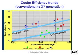
  • 44. © Confederation of Indian Industry Cooler Efficiency trends (conventional to 3rd generation)
  • 45. © Confederation of Indian Industry Cooler Efficiency Calculations Calculate total input air in kg air /kg clinker.  Total Input air= Cooler Vent Air + Recuperation Air(all value on mass basis) ESP Cooler vent Air Recuperation air
  • 46. © Confederation of Indian Industry Energy Balance of Cooler 4 COOLER Input heat from clinker Input heat from cooling air Heat losses from clinker SA+TA Cooler Vent Air Radiation & Convection losses
  • 47. © Confederation of Indian Industry Cooler Efficiency Calculations Input Heat from clinker = 0.2733 x(Inlet Clinker Temp-Refrence T ) Inlet Clinker temp = 1400 degree C Input heat from clinker = 382.6 kcal/kg clinker Input heat Cooling air = 17.9 kcal/kg clinker(ABC plant) Total input Heat = 400.5 kcal/kg clinker-------- Heat Output Heat through Vent Air = 92.2 kcal/kg clinker----------1 Heat through clinker = 26.9 kcal/kg clinker----------2 Radiation & Convection = 5 kcal/kg clinker---------------3 Heat through Water Spra = 37.7 kcal/kg clinker…………4
  • 48. © Confederation of Indian Industry Importance of cooler Efficiency Heat through Secondary & TA = Input Heat-(1+2+3+4) = 400.5-161.80 = 239 kcal/kg clinker Cooler recuperation efficiency = Heat through Secondary & tertiary Air x 100 Input heat from cooler = 60 %
  • 49. © Confederation of Indian Industry Important Facts-Cooler  The hotter the inlet temperature the hotter the clinker outlet temperature.  The hotter the cooling air temperature the hotter the clinker outlet temperature.  The longer the air/material contact time the cooler the clinker outlet temperature.
  • 50. © Confederation of Indian Industry Latest Generation of Coolers  FLS SF cross bar cooler  IKN pendulum cooler  Claudius Peters ETA (ɳ)cooler  CemProTec Revolving Disc Cooler (RDC)
  • 51. © Confederation of Indian Industry Major Developments SF Cross Bar Cooler- The 4 Innovative features:  Fixed grate line for air distribution  Conveying system separate from Cooling system  Grate plates with individual regulators for cooling air-Cooling Techniques – Unique  Modular design
  • 52. © Confederation of Indian Industry Mechanical Flow Regulation (MFR)  Classical compartment aeration  Each plate equipped with a mechanical flow regulator  Pressure drop across perforated plate controls regulator opening  Gives constant flow independently of clinker resistance  Eliminates need for air beam
  • 53. © Confederation of Indian Industry Operation of the (MFR)
  • 54. © Confederation of Indian Industry Effect of resistance grates
  • 55. © Confederation of Indian Industry Working of MFR
  • 56. © Confederation of Indian Industry 11/26/2020 Case Study of Cooler Upgrade with Cross Bar Cooler Parameter Unit Before After Production TPD 3150 3400 Cooler loss Kcal/ Kg Cl 135 98 SPC kWh/MT 5.7 5.17* Clinker temp Deg C 195 98 •Power includes Cooler Fans, cooler drives & HRB
  • 57. © Confederation of Indian Industry Hot Air Recirculation +20-25% More heat Waste Heat Recovery Maximised without compromising Recuperation Efficiency
  • 58. © Confederation of Indian Industry Waste Heat Recovery with hot air recirculation Mid air / WHR Vent air Secondary + Tertiary air
  • 59. © Confederation of Indian Industry IKN Pendulum Cooler  Pendulum cooler – IKN  Unique features  Stationary inlet  Coanda nozzle  Oscillating frames
  • 60. © Confederation of Indian Industry Coanda Nozzles  Narrow, inclined and curved slots in transport direction of clinker  Narrow sharp jet of air – 40 m/sec (Horizontal)  Fines are swept to the clinker bed surface, Coanda nozzles are completely engulfed by the cooling air  Fines always on top – Fluidized  Coarser pushed mechanically at the bottom  No Red river problem
  • 61. © Confederation of Indian Industry Oscillating Frames
  • 62. © Confederation of Indian Industry Features of IKN Cooler  Low Air requirement  Specific power consumption < 4 units/ton  Lower clinker temperatures < 100C
  • 63. © Confederation of Indian Industry Operating results before and after the IKN upgrade Before After Production rate (TPD) 5550 5750 TA Temp (oC) 760 930 Sp. Heat Consumption (kcal/kg clk) 710 690 Power in cooler section (kW/MT clk) 4.47 3.88 Cooler vent air temp (oC) 220 200 Clinker temp (oC) 152 132
  • 64. © Confederation of Indian Industry Revolving Disc Cooler (RDC)- 5th Generation Cooler
  • 65. © Confederation of Indian Industry  Introduced by CemProTec, Germany  Operates according to the “revolving disc” principle  The travelling grate is replaced by revolving disc  Under trial, results are being awaited Revolving Disc Cooler (RDC)- 5th Generation Cooler
  • 66. © Confederation of Indian Industry  Revolving disc – speed 30 min per round  High efficiency- 100% cross flow heat exchange  Low cooling air volume and hence exhaust air  No clinker spillage- Dust handling & transport system not required  100% transport efficiency  Very limited wear & maintenance Revolving Disc Cooler (RDC)- 5th Generation Cooler
  • 67. © Confederation of Indian Industry Benefits of Latest Generation High efficiency cooler  Better clinker properties  Lower exit gas and clinker temperature  Lower cooling air requirement  Total heat loss of latest generation cooler is less than 110 kcal/kg clk  Recuperation efficiency 75-80%  Retrofitting of existing conventional cooler with latest generation cooler offers significant potential for electrical and thermal energy saving
  • 68. © Confederation of Indian Industry Cooler Vent Fan  Typical power consumption  0.5 to 1.0 kW/ton  Typical pressure drops required  40 – 50 mmWC  Fan design (Head) very important  Natural draught available Example 220C, 55 m height
  • 69. © Confederation of Indian Industry Cooler vent fan PARAMETERS AFFECTING THE SEC OF COOLER VENT FAN  PRESSURE AT FAN INLET- Depends upon the pressure drop in cooler ESP and duct • Best observed value : 40 mmWc  EFFICIENCY OF FAN- Depends upon the fan design and operating parameters  CHIMNEY EFFECT- Depends upon the chimney height & dia.  LOSSES IN SPEED CONTROL- Depends upon the type of control installed Lowest observed SEC of Cooler vent fan : 0.13 kWh/MT clk
  • 70. © Confederation of Indian Industry How to choose best cooler System?  Minimum specific power consumption of cooler fans and vent fan  Cooler fans:-3-3.5 kWh/ton clinker  ESP Fans:-0.5-1.0 kWh/ton of clinker  Cooler recuperation efficiency should be greater than 70 %  Cooler Efficiency:-70-77%  Total losses:-110 kcal/kg clinker  (Cooler Vent + Radiation+Clinker)  Should be good in terms of maintenance point of view also
  • 71. © Confederation of Indian Industry Numerical No N1:-A grate cooler with cooler recuperation efficiency of 44% is to be replaced with high efficient cooler of 77% efficiency then calculate the benefit in terms of kcal/kg clinker? Also estimate the benefit in vent losses Present SEC-760 Kcal/kg clinker
  • 72. © Confederation of Indian Industry CFD Study & Thermal Efficiency Calculations
  • 73. © Confederation of Indian Industry Application of CFD to Improve Efficiency  Computational Fluid Dynamics (CFD) • Predicting the fluid flow related problem by solving mathematically, the equations which govern the process. • Numerical calculation method for solving fluid flow problems as possible, in solving practical engineering flow, heat transfer problem
  • 74. © Confederation of Indian Industry CFD – Application Areas Cyclone Ducts Electrostatic Precipitators (ESP) Baghouse Raw Mill/ Coal Mill Kiln/ Calciner Gas Conditioning Tower
  • 75. © Confederation of Indian Industry Application of CFD to Improve Efficiency  CFD study identifies the region offering high pressure drop, improper flow distribution, high velocity region etc.  Benefits of CFD study: Reducing the high pressure drop in pre-heater cyclones Reducing the high pressure drop in ducts Improving the cyclone efficiency
  • 76. © Confederation of Indian Industry Reasons for High PH Exit Temperature are  Improper material distribution  High velocity  High excess air  High return dust (low cyclone efficiency) Heat Transfer Analysis in Riser Duct for Flue gas with Particles elaborates the Temperature Thermal Efficiency Improvement in PH System
  • 77. © Confederation of Indian Industry By CFD analysis, the Exit Temperature Can Reduce & Reduction in Heat consumption about 5-20 kcal / kg clinker is possible. By means of  Modification in Riser Duct  Modification in Spreader Box & Feed Pipe  Modification in Cyclones Thermal Efficiency Improvement in PH System
  • 78. © Confederation of Indian Industry Velocity Distribution in Calciner  Benefits by CFD analysis in the Cal  Improvement in coal particle distribution  Improvement in flow Distribution of Velocities which improves the combustion  Reduces the high concentration of Temperature near the wall.  Improvement in residual time of the Particle  Overall improvement in calcinations Particle Trajectory in Calciner Thermal Efficiency Improvement in Calciner
  • 79. © Confederation of Indian Industry Cyclone Performance Analysis Pre-modified duct
  • 80. © Confederation of Indian Industry CFD Analysis PH system Streamlines plot at the inlet duct of III stage cyclone Reduction in Pressure drop up to 20mm WC
  • 81. © Confederation of Indian Industry CFD Analysis for PH system Project Completed and analysis report shows pressure drop up to 25mm WC
  • 82. © Confederation of Indian Industry Pre-modified Cyclone analysis with duct Modified Cyclone analysis with duct Cyclone Performance Analysis Reduced pressure drop by 60 mm WC(10% reduction in Fan Power). Energy savings 50 KW/h. Payback period less than 4 months.
  • 83. © Confederation of Indian Industry Dust loss from Pre-heater system/Improvement of Cyclone Efficiency By CFD study PH & PC Feed 300 tph 75°C Dust loss – 30 tph 275°C  Top cyclone eff  Design – 96 %  Actual – 90 %  Equivalent heat loss – 10 kcal /kg
  • 84. © Confederation of Indian Industry Dust loss from Pre-heater system / Improvement of Cyclone Efficiency By CFD study  Pre-heater dust loss – 10 %  Dust goes out at about 275ºC  Fresh feed enters at 75ºC  Material heat loss alone – 10.0 kcal/kg  Top cyclone efficiency increase of 3 % means -3.0 kcal/kg
  • 85. © Confederation of Indian Industry Dust loss from Pre-heater system / Improvement of Cyclone Efficiency By CFD study  Excellent opportunity  CII had discussions with consultants on reducing dust loss thro CFD analysis & retrofit  Consultant positive on dust loss reduction without increasing pressure drop  Has been successful in several Cement plants
  • 86. © Confederation of Indian Industry Improvement of Cyclone Efficiency By CFD study Present Cyclone Efficiency = 90% Design Efficiency = 96% Kiln feed to clinker Factor = 1.6 Fresh Feed enters at temperature 75 degree C Present dust loss = 0.10X1.60 = 0.16 kg material Present heat loss = 0.16x0.23x275 = 10 kcal/kg clinker
  • 87. © Confederation of Indian Industry Improvement of Cyclone Efficiency By CFD study Recoverable is 3% Improving in efficiency by CFD study(Considering 93%) = 0.07*1.60 = 0.112 Benefit in dust loss = 0.16-0.112 = 0.048 kg material Heat improvement = 0.048xspecific heat of flue gasesxT Q = 0.048x0.23x(275-0) = 3.03 kcal/kg clinker
  • 88. © Confederation of Indian Industry Calculations Thermal cost = RS 1100 Mkcal (Million kilo calorie) Clinker production :- 4500 ton/day; NCV of coal = 7000 kcal/kg coal Overall Heat saving per day = 3x4500x1000 = 13.5 Mkcal per day
  • 89. © Confederation of Indian Industry 13.5 Mkcal per day/ In terms of coal = 1.92 ton of coal in a day No of days per annum = 300 = 13.5x300 = (4050) Mkcal - Energy saving per annum = 4050 x 1100 Savings = Rs 44.55 lakhs per annum Investment = 20 lakhs Payback = 20 X12 44.55 = 6 months Calculations
  • 90. © Confederation of Indian Industry Dust loss from Pre-heater system/ Improvement of Cyclone Efficiency By CFD study  I Step  Conducted CFD analysis for top cyclone  Implement retrofits to improve efficiency  Target efficiency - 93 %  Improvement in efficiency – 3 kcal / kg clinker Saving - Rs. 44.50 lakhs Investment - Rs. 20 lakhs Payback - 6 months
  • 91. © Confederation of Indian Industry Minimize Heat Loss in Tertiary Air Duct Cooler PC 950oC 840oC Heat Loss •Air infiltration in TA duct •Surface Heat Loss
  • 92. © Confederation of Indian Industry TA Duct – Thermograph Images
  • 93. © Confederation of Indian Industry TA Duct – Thermograph Images
  • 94. © Confederation of Indian Industry Minimize heat loss in TA Duct  Air infiltration  Atmospheric air entry  Reduces Air intake from Cooler  Cooler vent – higher temperature  Arresting air infiltration  Lower ambient air ingress  Increases cooler air utilization (at Temp of about 500 Deg C)
  • 95. © Confederation of Indian Industry Minimize heat loss in TA duct  Surface insulation  Hot spots observed > 200 Deg C  Significant drop between cooler & PC  Radiation loss estimated > 5 kCal/kg Cl  Loss due to air infiltration ~ 3 kCal/kg Cl  TARGET – 30-40oC drop between cooler exit and PC
  • 96. © Confederation of Indian Industry Calculations Present Temperature Drop:- = 950-840 = 110 oC Margin in temperature = 110-40 = 70 oC Considering recuperation air = 0.80 Nm3/kg clinker Total air requirement for calciner = 0.60 x 0.80 = 0.48 Nm3/kg clinker Mass = 0.48 x1.29 = 0.6192 kg air/kg clinker = 0.6192 x 0.25x 70 = 10.836 kcal/kg clinker benefit
  • 97. © Confederation of Indian Industry Calculations Thermal cost = Rs 1100 Mkcal (million kilo calorie) Clinker production = Rs 4500 ton/day NCV of coal = 7000 kcal/kg coal Overall Heat saving per day = 10.836x4500x1000 = 48.76 Mkcal per day/ In terms of coal = 6.96 ton of coal in a day
  • 98. © Confederation of Indian Industry Calculations  No of days per annum:= 300 = 48.76x300 = (14628) Mkcal Energy saving per annum Annual Saving = 14628 x 1100 = Rs 160.90 lakhs per annum Investment = 70 lakhs Payback = 70 X 12 160.96 = 6 months
  • 99. © Confederation of Indian Industry Minimize heat loss in TA duct  Annual Saving - Rs 160.90 Lakhs  Investment - Rs 70.0 Lakhs  Payback period - 6 Months
  • 100. © Confederation of Indian Industry Reduce PH exit temperature 1 A 1 B 2 3 4 5 1 A 1 B 2 3 4 5 325 oC 293 oC 502 oC 659 oC 815 oC 893 oC 478 oC 650 oC 799 oC 890 oC Standard profile Case stufy plant profile ILC ILC
  • 101. © Confederation of Indian Industry Lower Dispersion Box in riser ducts and increase heat transfer  PH system – heat transfer  Overall – Counter current  Each Stage – Co-current  Maximum heat transfer in riser ducts  Separation of material & air in cyclones  Very little heat transfer in cyclones
  • 102. © Confederation of Indian Industry Lower Dispersion Box in riser ducts and increase heat transfer  Latest approach  Locate feed pipe as low as possible  Increases heat transfer in riser ducts  Lowers PH gas exit temperature  Discussions with Suppliers & other Cement Plants  Favor this step (Upto 1 m, easy)  Implemented in several plants
  • 103. © Confederation of Indian Industry
  • 104. © Confederation of Indian Industry Present System Kiln String Calciner String Dispersion Box Height Total Riser Height Dispersion Box Height Total Riser Height 5.055 16.932 2.953 14.570 3.0 12.8 2.947 12.392 5.435 12.78 3.335 13.2 2.1 12 3.053 12.918 4.435 13.4 4.7 -
  • 105. © Confederation of Indian Industry  Good potential to lower the feed point  Discussion with supplier before implementation  Saving of 10-15oC  2.5 - 3 kCal / kg of clinker, At least  Recommended to take up one by one  Monitor temp & pressure profiles closely Lower Dispersion Box in riser ducts and increase heat transfer
  • 106. © Confederation of Indian Industry Lower Dispersion Box in riser ducts and increase heat transfer Annual Saving - Rs 34.98 Lakhs Investment - Rs 6.0 Lakhs Payback period - 2 Months
  • 107. © Confederation of Indian Industry Reduce cold air entry into system  Cold air entry in Kiln and Pre-heater system  Coal conveying  Primary air  Coal conveying offers a good potential for energy saving  Presently coal conveying air – ~ 16.0 tph  Same irrespective of type of coal used  Equivalent heat loss with air finally going out at 265°C is – 1.50 kcal/kg
  • 108. © Confederation of Indian Industry Reduce cold air entry into system..  Phase density for FK pumps – up to 7 possible  Present phase density – 2 to 2.5  Varies depending on the coal used and the fineness  Good potential to reduce  Install VFD for all four coal conveying blowers  Reduce rpm in a phased manner  5 % steps and observe performance  Target speed reduction – 20 - 25%
  • 109. © Confederation of Indian Industry Reduce cold air entry into system Saving - Rs. 26.61 Lakhs Investment - Rs. 30.0 lakhs Payback - 14 months
  • 110. © Confederation of Indian Industry Impact of False Air on fuel & Electrical Consumption O2-5% 1 2 3 4 PH FAN 5 6 Calcine r kiln Kiln Feed O2-2.5% Measuring Points 1) Calciner Outlet 2) Preheater down Comer 3) Fan Inlet Temp-275 degree C Fan Inlet pressure-600 mmwg
  • 111. © Confederation of Indian Industry Calculations  Preheater Down Comer:-5%  Calciner Outlet:-2.5% Apply False Air Formula = (Down Comer oxygen-Calciner outlet) X 100 ( 21-calciner outlet oxygen) = 5-2.5 X 100 21-2.5 = 13.5 % Consider preheater outlet Temperature :- 275 degree C Considering Reduction in false air :- 5% Present Flow: - 1.50 Nm3/kg Clinker
  • 112. © Confederation of Indian Industry Impact of False Air on fuel Consumption Mass Flow Rate = 1.50x1.42 = 2.13 kg gases /kg clinker Reduction in mass flow by reducing FA = 0.05x2.13 = 0.1065 kg/kg clinker Heat Loss = 0.1065xspecific heat of flue gasesxTemp difference
  • 113. © Confederation of Indian Industry Impact of False Air on fuel Consumption Q = 0.1065x0.23x(275-0) = 6.73 kcal/kg clinker. Thermal cost = RS 1100 Mkcal (million kilo calorie) Clinker production:- = 4500 ton/day NCV of Coal = 7000 kcal/kg coal
  • 114. © Confederation of Indian Industry Overall Heat loss per day = 6.73x4500x1000 = 30285000 kcal per day In terms of coal = 4.326 ton of coal in a day No of days per annum: = 300 = 30285000x300 = (9,085) Mkcal - energy saving per annum In terms of Mkcal = (9.085x10^9)/(10^6) = 9.085x(10^3 ) Cost = 9085 x 1100 Saving = Rs 99.93 lakhs per annum Impact of False Air on fuel Consumption
  • 115. © Confederation of Indian Industry Impact of False Air on Electrical power Electrical Loss = Percentage of false airX electrical power of fan Electrical power = 1400 kW Power loss = 0.05x1400 = 70 kW Electrical cost = Rs 5 kWh No of days per annum: -300 Annual Saving = 135x300x5x24 = 25.2 lakhs per annum Total Saving = 99.93+25.2 = 125 lakhs
  • 116. © Confederation of Indian Industry Impact of False Air on Electrical power Saving - Rs. 125. Lakhs Investment - Rs. 50.0 lakhs Payback - 5 months Pay back = (50/125)x12 = 5 months
  • 117. © Confederation of Indian Industry Burners  The ultimate objective of a burner is to provide a stable short and intense flame for burning of raw materials to the desired temperature and achieve heat economy  More efficient mixing of fuel and air  Improvement in entrainment of secondary air
  • 118. © Confederation of Indian Industry First Generation Burners(conventional) Advantages  Burning traditional Fuels  Good Flame Adjustability  Good Mixing of the combustion air with the Fuel Disadvantages  Generation of high Nitrogen oxides emissions  Inability to use market dependent alternate fuels
  • 119. © Confederation of Indian Industry Second Generation burner(Multichannel) Duoflex burner:-FLS Pyrojet:-KHD Pillard:-Rotaflam Greco:-Greco
  • 120. © Confederation of Indian Industry How to select best burner for the plant operation?  Adjustability of the flame shape to suit the kiln operation and type of fuel  Operating costs and servicing costs Other Important process parameters  Primary air requirement(%) & pressure(effect the energy cons.)  Flame momentum  Coal conveying air(solid loading ratio)  NOX emissions (Low NOX burner) Emission behavior with respect to NOx emissions  Flexibility with traditional fuels  Flexibility with market-dependent alternative fuels
  • 121. © Confederation of Indian Industry NOX Generation  Thermal NOX  Form in burning zone and reaction takes place at high temperature(1400 degree C) 2N2+O2-2NO +N N+O2-NO+O  Higher excess air results high amount of NOX  As Input N2 increases due to excess air  High residence time in calciner also increase the NOX formation
  • 122. © Confederation of Indian Industry NOX Generation Fuel NOX  Fuel NOx is formed by the oxidation of nitrogen present in fuel  A study has indicated that gas-fired, dry-process kilns typically produce almost three times more NOx than coal- fired, dry-process kilns  Fuel NOx predominates NOx generation in the calciner and at lower-temperature combustion sites.  Approximately 60% of fuel nitrogen is converted to NOx and is dependent upon available oxygen in the flame and temperature profile
  • 123. © Confederation of Indian Industry Low NOx Burners (Latest generation Burners) Parameters FLS –Jet Flex Novaflam KHD Pyrojet Type of Fuel Coal or Pet coke Coal or Pet coke Coal or Pet coke Transport Air volumetric flow for pet coke 2805 m3/hr 2135 Nm3/hr 2165 Nm3/hr Solid loading factor-coal 3.8 4.96 kg coal/Nm3 4.90 kg coal/Nm3 Primary air cons(%) 5-6% 6.5% 4.8% Primary air pressure(mbar) 700 500 Jet-900;swirl-160 Primary air flow 5100 m3/hr. 5500 Nm3/hr Jet-2710m3/hr;swirl:- 1355 m3/hr Burner out put(68 MW) Primary air consumption:- 8-9% in ordinary multichannel burner with low pressure(1500-2500 mmwg).
  • 124. © Confederation of Indian Industry Low NOx burner Concept  Less primary air means less oxygen and may produce an initial high-temperature, fuel-rich combustion zone, followed by a low-temperature fuel-lean combustion zone. Such a combination is likely to reduce the formation of NOx.  Reduce flame turbulence, delay fuel & air mixing and establish fuel rich zones for initial combustion  A fuel-rich, oxygen-lean, high temperature combustion zone is created first by reducing the amount of primary air in the primary combustion zone and delaying the combustion of all of the fuel
  • 125. © Confederation of Indian Industry NOX reduction-solutions(Primary level)  Reducing excess air levels also results in increased productivity per unit of energy; thus, resulting in the indirect reduction of NOx emissions per amount of clinker produced.  Improving burnability of kiln feed & thermal efficiency of the system  Reduction in heat consumption  Installing the low NOX burner  Change in the preheater system(hot bottom formation in ILC)  Nitrogen content in the fuel  Latest developments by technology suppliers
  • 126. © Confederation of Indian Industry Case Study No1 Objective Toreduce the primary air percentage by installing pillard Novaflame burner Primary air consumption:-12% Problems:- Frequent build up in the 28th m of the kiln Benefits:- After changing the burner the coating tendencies are reduced and plant team are able to increase the petcoke to 100%.
  • 127. © Confederation of Indian Industry Case Study Project Economics:- Energy saving:-2 kcal per kg clinker Total fuel saving:-350 tonnage of coal Cost :-Rs 6500 per ton of coal Total cost saving:-Rs 23 lakhs per annum Investment:-Rs 52 lakhs Payback:-27 months
  • 128. © Confederation of Indian Industry Case Study No2  Pyro-Jet Burner was commissioned successfully and Primary Air consumption reduced by 5% thereby Heat consumption reduced by 5 Kcal/ kg clinker
  • 129. © Confederation of Indian Industry Latest Developments:-KHD Pyroclon-R Low NOx
  • 130. © Confederation of Indian Industry Fuel PYROREDX Reactor Main Calciner ① ② Technology  Gasifying reactor between kiln and calciner.  Formation of CO by Boudouard reaction.  Reduction of NOx.  Suppression of fuel NOx formation. PYROCLON® Redox Reactor-For low NOX
  • 131. © Confederation of Indian Industry PYROCLON® Redox Reactor-For low NOX
  • 132. © Confederation of Indian Industry Redox reactor inlet Gas Composition: CO2 19.4 Vol.% CO 0 Vol.% 100 % Of Calciner Fuel fired in PYROREDOX duct in Kiln Flue gas only, Without any TERTIARY Air admission hence Reducing atmosphere ( Insufficient Combustion air / Starved O2 Condition ) Created In PYROREDOX. Due to reducing atmospheres in PYROREDOX, the CO2 in kiln flue gas react with fuel C which is sub stoichiometric conditions. The sub stoichiometric reaction as follows and it produces CO at the same time CO2 content of flue gas reduces to 8.1 % , hence Conversion of NO into N2 using CO is > 95 % CO2 + C  2 CO Boudouard reaction Working Principle
  • 133. © Confederation of Indian Industry Working Principle  Redox reactor outlet / Calciner Inlet Gas Composition:  CO2 8.1 Vol.% `  CO 21.8 Vol.%  The above condition is very favorable for DENOX Reaction using CO as Follows  2CO + 2NO = 2CO2 + N2  Final NOX CONCENTRATION IN CALCINER OUTLET IS < 500 mg/Nm3 @ 10 % O
  • 134. © Confederation of Indian Industry  Typical pressure drops - Latest PH with PC  4 Stage – 310 to 360 mmwg  5 Stage – 350 to 400 mmwg  6 Stage – 450 mmwg Low Pressure Drop Cyclones
  • 135. © Confederation of Indian Industry Latest development in Cyclones by KHD Previous Cyclone Design 55% dip tube ratio Inlet cross section 100% h/w = 1,6 High Efficiency (HE) Cyclone Design for > 60% dip tube ratio New 110% h/w = 2,0 Benefits Based on same capacity  Dp saving of 1,5 - 2 mbar per cyclone stage  Smaller Cyclone size can be used  Less equipment and building expenditure
  • 136. © Confederation of Indian Industry New design 6852 HE / 5 25,5 mbar 22,6 mbar 11,1 mbar 7,1 mbar 36,6 mbar 29,7 mbar Cyclone Developments –CASE STUDY Existing design 7950/5 Double Separator: • increased by one size System Cyclones: • reduced by one size • new design of gas inlet • increased dip tupe ratio Reduction building height Approx. 3 % Reduction foot print Approx. 5 % Reduction building volume complete Approx. 10 to 15 %
  • 137. © Confederation of Indian Industry CCX Cyclone by FLS 1. Material top feed 2. Rotating spreader (Counter current heat exchange) 3. Integrated heat exchange and separation 4. Light weight lining 5. Central pipe is pointing upwards 6. Exit gas outlet naturally pointing downwards 7. Reduced civil & Structural loads 1 2 5 6 3 4 7
  • 138. © Confederation of Indian Industry CCX Cyclone by FLS
  • 139. © Confederation of Indian Industry Standard Cyclone HR+ Counter Current Cyclone CCX Gas out Gas In Material In Material Out Gas In Material In Material Out Gas out CCX Cyclone by FLS
  • 140. © Confederation of Indian Industry CASE STUDY-European Cement Plant Kiln capacity, clinker Operating at ~ 3300 tpd Production increase (tpd) ~ 200 tpd Pressure drop reduction 40% Recorded gas material temp. difference 50-60°C Fuel savings 8-10 kcal / kg cl Cyclone heat efficiency recorded 1.5 Load on civil structure reduced > 50% Existing top cyclone modified to CCX 6.3m.
  • 141. © Confederation of Indian Industry Latest developments in Calciners
  • 142. © Confederation of Indian Industry Requirements for Modern Precalciners Stable operation for full decarbonation (60 to 65 % fuel burnt in calciner ) Full combustion of all fuels Maximum alternative fuels (solid and lumpy) Control of emissions (NOx, CO , TOC/VOC )
  • 143. © Confederation of Indian Industry FLS In-line calciner Restriction area Mixing zone Splitter gate Splitter gate Reduction zone Kiln riser Raw meal duct Fuel Vmin(ILC) = 6m/s Retention time (ILC) = 3.3s Low Nox Calciners for reduced Nox emissions irrespective of fuel
  • 144. © Confederation of Indian Industry FLS Separate Line Calciner - Downdraft 144 Characterizes a special type of burner arrangement and flow path. Flow is down draft. Geometry is designed for instant ignition of combustible.  Complete burnout of low volatile fuels high combustion temperatures High material and gas retention time in the calciner
  • 145. © Confederation of Indian Industry Developments in KHD Calciner
  • 146. © Confederation of Indian Industry PYROCLON® Calciner Technology - Steps of Developments Pyroclon-R LowNOx ILC - staged combustion „The first LowNOx Calciner 1980“ Pyroclon-R LowNOx AF ILC - staged combustion and AF utilisation Pyroclon-R LowNOx „LRF“ Variant for „Low Reactive Fuels“ (e.g. Petcoke)
  • 147. © Confederation of Indian Industry PYROCLON® Calciner Technology - Steps of Developments Pyroclon-REDOX ILC with PYROREDOX Pyroclon-R LowNOx Pyroclon-R LowNOx AF Pyroclon-R LowNOx „LRF“
  • 148. © Confederation of Indian Industry Raw Mix  To achieve the goal of smooth kiln operation it is necessary to know  Which parameters in the raw mix influence kiln operation?  How and why they influence operation?  What can be done about it ?
  • 149. © Confederation of Indian Industry Raw Mix design  Main Parameters of Raw Mix design  Lime Saturation Factor  Silica Modulus  Alumina Modulus Range:- LSF SM AM
  • 150. © Confederation of Indian Industry Raw mix design Software - - - - - - - - - RAWMIX DESIGN - - - - - - - - - LIMESTONE SHALE IRON ORE BAUXITE RAWMEAL MIX % 82.14 14.13 0.94 2.79 100.00 SiO2 3.24 74.98 9.16 9.00 13.59 Al2O3 0.79 8.80 2.00 50.00 3.30 RAWMEAL Fe2O3 0.38 6.20 83.04 14.00 2.36 TARGETS CaO 51.00 0.98 0.06 5.50 42.19 MgO 1.24 0.24 0.41 0.50 1.07 Lime Saturation K2O 0.50 0.30 0.20 0.10 0.46 97.00 Na2O 0.20 0.20 0.10 0.10 0.20 SO3 0.10 0.20 0.07 0.05 0.11 Silica Modulus L.O.I. 42.48 8.00 4.65 21.00 36.65 2.40 TOTAL 99.93 99.90 99.69 100.25 99.93 S.R. 2.40 Alumina Modulus A.R. 1.40 1.40 L.S.F. 97.00 `
  • 151. © Confederation of Indian Industry Liquid phase variation by Silica& Alumina Ratio
  • 152. © Confederation of Indian Industry Importance of Liquid phase  SM decreases as liquid phase increases & vice versa  AM also changes as per liquid content in the clinker  Significance  Clinker granulation  Coating (but also formation of rings)  Rate of alite formation
  • 153. © Confederation of Indian Industry Importance of Liquid phase Typical amount 20 –30 %  Dry: ≤ 23 %  Normal: 23 – 27 %  Wet ≥ 27% Liquid Viscosity:  Decreases with increasing temperature  Depending on composition and minor elements  Reduced by Na2O, CaO, MgO, Fe2O3, MnO  Increased by SiO2, Al2O3
  • 154. © Confederation of Indian Industry C2S,C3S,C3A & C4AF Formation reactions-1300 degree C
  • 155. © Confederation of Indian Industry C2S,C3S,C3A & C4AF Formation reactions-1400 degree C
  • 156. © Confederation of Indian Industry Formation of clinker
  • 157. © Confederation of Indian Industry Kiln Challenges-Petcoke  Grinding problems in coal mill  Minimizing the residue is a difficult task(Lower HGI)  Low volatile matter  Requires high flame momentum in kiln  Chances of refractory damage is high due to FM  High content of Sulphur  Condensation of sulphates in preheater(5th & 6th cyclone) resulting in jamming of process flows , defined as volatile cycle
  • 158. © Confederation of Indian Industry Recommendations  Use of high flame momentum burner  KHD pyrojet, FLS Jet flex ,Novaflam  Alkalies(K2O,Na2O),lime for raw meal and SO2 from petcoke  Optimize alkali Sulphur ratio  Operate the kiln in oxidizing atmosphere with excess of oxygen  Excess oxygen:-4%(kiln inlet for petcoke)
  • 159. © Confederation of Indian Industry Recommendations  Install UT pump and blasters at kiln inlet  Reduce filling inside the kiln (12-13%)  Increase retention time in the calciner  Avoid CO formation by maintaining the residue below 2% on 90 micron.  Use Silica Carbide castable at inlet and burner pipes to reduce coating
  • 160. © Confederation of Indian Industry Alkali Sulphur ratio Volatile Cycle:- Sulphur to alkali ratio decide the type of coating formed Q = %SO3 / 80 Na2O/62 +(K2O/94)-(Cl/71) Sulphur excess Q>1 = Hard coating Alkali excess Q<1 = Soft coating
  • 161. © Confederation of Indian Industry Chemistry  To prevent SO2 gas leave from the kiln, it must be combined with alkalies(Na,Ca&K) and form sulphates(Na2SO4,K2SO4) and leave with clinker in the form of sulphates.  Sufficient amount of liquid is required for above reactions  AM:-1.2  Excess oxygen is required for maintaining oxidizing atmosphere CaO+SO2+1/2 O2 = CaSO4  SO3 in clinker may be maintained in the range:1.5-2%
  • 162. © Confederation of Indian Industry Rings Formations
  • 163. © Confederation of Indian Industry Important Thumb rules  10% excess air is equivalent to heat loss of 10 kcal/kg clinker  False air acceptable range across preheater system is 6-8%, above it only contributes heat losses in the system  Kiln inlet O2:-2% -Normal Coal;O2:-4%:-Pet coke  Rate of heat transfer increases as the kiln rpm increases the recommended filling inside the kiln of normal coal is 14-15 % and for pet coke is 12- 13%.
  • 164. © Confederation of Indian Industry Important Thumb rules  It is recommended that to reduce the filling in the case of petcoke due to Sulphur content in it which vaporize in burning zone and increase the tendency of coating formations at 5th and 6th cyclones.  Burning zone temperature is directly proportional to square of diameter of raw meal particle,therefore,another way is to optimize the process by controlling the residue of raw meal(15- 16%) on 90 micron
  • 165. © Confederation of Indian Industry Important Thumb rules  Recommended Cooler grate loading:-  Kiln Loading:-  Input cooler Air:-1.75 Nm3/kg clinker-Normal Coal :-1.80 Nm3/kg Clinker-petcoke  Optimize the cooler vent air by identifying the cooler null point .  Heat and mass balance study of pyro section is to be checked by doing mass balance.
  • 166. © Confederation of Indian Industry Important Thumb rules  Radiation losses contribute 6-8% of total radiation losses  Coal conveying pipeline velocity :-25 -26 m/s  Recommended Phase density :-3-4 kg coal/kg air-Normal Coal :-4-6 kg coal/kg air-pet coke
  • 167. © Confederation of Indian Industry CASE STUDIES
  • 168. © Confederation of Indian Industry Case Study No1 Usage of Pyrolytic Oil for Kiln Light up Parameter Unit Pyrolytic Oil Diesel Moisture % 0 0 ASH % 0.025 0 GCV Cal/g 10134 9600 NCV Cal/g 10134 9600 Chloride % 0.23 0.08 Sulfur % 0.69 0.21 Density Kg/m3 0.88 0.83 Flush point Degree C 35 46
  • 169. © Confederation of Indian Industry SOP FOR KILN LIGHT UP THROUGH PYROLYTIC OIL  Placing of Oil Tanker at safe place( plain & leveled surface)  Proper dual Earthling for discharging of static charge of oil tanker.  Direct connection to Pump inlet through a T-joint with manual control valve.  First firing started with Diesel and after 4Hrs switch to Pyrolytic oil.  Diesel firing stopped completely during usage of pyrolytic oil.  Separate feeding mechanism provided for Pyro-oil firing.  Two pump provided, in case of one pump failure other will start.  Oil Flow can be maintained from control valve (MCV1) near pump by checking pressure in installed pressure gauge.  Pressure maintained between 6 to 7 bar.  In case of fluctuation in pressure gauge, filter was clean up which installed just before pump.
  • 170. © Confederation of Indian Industry SOP FOR KILN LIGHT UP THROUGH PYROLYTIC OIL  Flow-rate maintained 0.6 KL/Hr. After 36 Hrs. 21.75 KL pyrolytic oil consumed in kiln light up.  Recorded the temperature profile hourly.  Coal firing started after 9 hours by checking kiln inlet temperature
  • 171. © Confederation of Indian Industry Tech. Parameter Value Unit Cost of Diesel 61912 Rs/KL Cost of Pyrolytic Oil 26800 Rs/ KL NCV of Diesel 9600 Kcal/Kg NCV of Py-oil 10134 Kcal/Kg Replacement Ratio 1.05 Net Cash Benefit (NCB) -26800 Rs/ KL Substitute benefit (SB) 65355.8 Rs/KL Gross Added Value (GAV) 38555.8 Rs/KL Benefits
  • 172. © Confederation of Indian Industry Case Study No2: De-Swirler Installation in PH Top Cyclone of Kiln-4 Observation : In Kiln-4, PH Fan-2 SPC was high up to 4.42 kWh/T Clk (w/O SPRS Recovery). Problem : While conducting the pressure profile mapping identified top- cyclone pressure-drop was in range of 85-90 mmWG. Solution Adopted : CFD analysis was conducted to identify the regions for excess pressure drop in cyclone & what rectifications can be initiated to reduce this. Modification Done : Based on the recommendations of CFD team, we modified the dip-tube of top cyclone (shown in figure) to reduce the vortex formation without affecting the cyclone collection efficiency.
  • 173. © Confederation of Indian Industry Case Study No2: De-Swirler Installation in PH Top Cyclone of Kiln-4 Impact : Pressure drop in the cyclone is now reduced up to 65 mmwg Savings Achieved : Daily Power Savings : 1,050 kWh, Daily Monetary Savings : Rs 3,990 @ Rs 3.8/kWh, Rs 13.00 Lacs / Year Replicability: Cyclones having issues of high pressure drop & maximum operating temperature range of up to 500 Degree Celsius.
  • 174. © Confederation of Indian Industry Parameters Unit Before Period After Period Kiln Feed Avg TPH 704 726 Fan Speed 2 RPM 769 766 Load-2 kW 1957 1974 SPC Fan-2 kW/T Clk 4.42 4.32 Avg. Pressure Drop across Top Cyclone- String 3 & 4 mmWg 84 65 De-Swirler Installation in PH Top Cyclone of Kiln-4
  • 175. © Confederation of Indian Industry Observations 1. Kiln Shell Temperature : 200 Deg C 2. Average Radiation Loss : 3. Heat Loss in % : 6% Action Taken: 1. To Install Radiation Heat Recovery Panels 2. Generation of 100 Deg C Hot Water 3. Operation of VAM Chiller with Hot Water (1 X 85 TR) 4. Stopping of Conventional Chiller (1 X 85TR) Case Study No3 Kiln Radiation Heat Recovery for AC (VAM Chiller)
  • 176. © Confederation of Indian Industry Hot Water to VAM Chiller Kiln Radiation Heat Recovery for AC (VAM Chiller)
  • 177. © Confederation of Indian Industry 1. Recovering the Waste Heat from Kiln Shell 2. Operation of VAM Chiller and Stopping Electrical Chiller. 3. Power Saving of 70 KW / Hr. 4. Energy Saving : 1680 Units / Day (5.54 Lakh Units/ Annum) 5. Cost Saving is Rs. 30.25 Lakhs / Annum Kiln Radiation Heat Recovery for AC (VAM Chiller)
  • 178. © Confederation of Indian Industry Case Study-4 Cooler Hot Air Recirculation Objective: To Reroute hot air from Line 1 ESP Stack to cooler inlet. This will improve line 1 WHRS AQC 1 Boiler inlet temperature. Benefits: Increase Power Generation of WHRS by 0.3MW Power Savings of 23.76 Lacs Kwh Investment of Rs. 200 Lacs
  • 179. © Confederation of Indian Industry Case Study 5 Formation of TAD ramp to increase the oxygen concentration at kiln inlet Problem:-  High CO formation at kiln inlet (ILC KILN) Reason:-  There was no damper in TAD because whatever the damper the plant team installed worn out within 7-8 months as a consequent CCR operators was not able to pick the kiln due to CO formation
  • 180. © Confederation of Indian Industry Formation of TAD ramp to increase the oxygen concentration at kiln inlet Counter Measures:-  Installation of ramp inside the TAD which blocks around 40 % area of TAD  Optimize the raw mix as per pet coke  Optimize the residue on Petcoke(2-3% on 90 micron)
  • 181. © Confederation of Indian Industry Benefits  Kiln output has been increased from 220 TPH to 300 TPH  Smooth kiln operation  Benefit in specific heat consumption  Total investment:-Rs 1 lakh(castable & labor)
  • 182. © Confederation of Indian Industry Case Study No 6 MgO added as Mineralizer through Kiln firing Project Concept  Clinkerisation is an energy intensive process and it is influenced to a large extent by the chemistry and mineralogy of the raw materials used.  In the burning zone, where the formation of C3S occurs by diffusion reaction between C2S and free lime, the liquid phase plays a very important role.  .
  • 183. © Confederation of Indian Industry MgO added as Mineralizer through Kiln firing  Many of the problems such as dusty clinker formation, inadequate porous or excessive coating formation ,high levels of uncombined lime are attributed to the unfavorable viscosity of the melt phase especially when Sulphur rich fuels are used  It is possible to modify the viscosity of the melt phase through use of various additives including alkalis.  However, in dry process kilns with suspension preheaters, there are limitations on the use of alkalis.
  • 184. © Confederation of Indian Industry MgO added as Mineralizer through Kiln firing Concept & Principle  The most compatible and least harmful and yet economical additive is magnesia. It improves the viscosity of the melt phase and therefore aids in the combinability of lime with C2S. As a result of this, the free lime is reduced and the C3S formation is enhanced.
  • 185. © Confederation of Indian Industry MgO added as Mineralizer through Kiln firing Execution Methodology  Addition of Dolomitic Limestone with the MgO range of 13 - 15 % at the rate of 1 % with respect to Clinker Production of 7000 TPD.  Point pile quantity of 3000 Tons was made through LS Crusher/CPP Crusher  Crushed material stored in the outside yard and fed to the Coal crusher along with the Coal pile .  Fine grinding with PetCoke in Coal Mill then fed to the Kiln Main burner.  Reduction in Kiln Primary Fuel and change in raw mix design with Less iron changed
  • 186. © Confederation of Indian Industry MgO added as Mineralizer through Kiln firing  XRD analysis of clinkers show positive effect of MgO addition
  • 187. © Confederation of Indian Industry Benefits  The MgO modifies the viscosity of the melt phase and changes the liquid phase composition  The effect is seen both in terms of reduction in free lime content and enhancement of C3S contents and its modification to high temperature polymorphic  Clinker shown better granulometry and grindability characteristics as the C3S content is increased with concomitant reduction in C2S MgO added as Mineralizer through Kiln firing
  • 188. © Confederation of Indian Industry MgO added as Mineralizer through Kiln firing Results:- Project involves No Capex or Opex expenditure. Cost Savings are as follows without any investment :  Cost savings due to Power - ₹ 1.59 Crores/Annum  Cost savings due to SHC - ₹ 69.33 lacs/Annum  Total Cost Savings - ₹ 2.28 Crores/Annum Replication potential:- 100% replication potential in Cement Sector for all Dry process Inline Calciner Kilns
  • 189. © Confederation of Indian Industry Key Points  SEC of Preheater fan can be reduced by minimizing the pressure drop and optimizing the velocity profile across preheater system by using efficient cyclones (low pressure drop) and avoiding the coating formations at kiln inlet & cyclones(5th & 6th)  Optimizing the excess air leads to tremendous potential in thermal energy saving potential  Excess air 10% is equivalent to loss of 8-10 kcal per kg clinker  Secondary air temperature plays an important role in optimizing the flame length  Recommended Velocity:-5 m/s
  • 190. © Confederation of Indian Industry Key points  Latest generation coolers have the potential to face the challenges of snow men formation and red river in the cooler by installing latest device in the cooler such as MFR (Mechanical flow regulator) and through conada effect.  Plant can improve the thermal efficiency of cooler by reducing vent losses and improving the recuperation air temperature by avoiding leakages  Recommended parameters  70% efficiency  Cooler losses:-110-120 kcal/kg clinker  Vent air:-1 Nm3/kg clinker
  • 191. © Confederation of Indian Industry Key points  CFD study is new era in the field of cement industry through which lots of modification can be done both thermal as well as electrical  Improving Cyclone Efficiency through CFD study  Reducing the system resistance across ducts &cyclones  Latest development in cyclones ,Latest generation burners(Low NOx) and other developments regarding reducing NOX have increased the productivity as well as fulfill the environment norms with output  Latest in-house modifications such as TAD ramp and utilization of MgO in kiln are the evidences there is enough potential of improvement in pyro process with low investment
  • 192. © Confederation of Indian Industry Annexures
  • 193. © Confederation of Indian Industry Annexures
  • 194. © Confederation of Indian Industry http://energy.greenbusinesscentre.com/ THANK YOU ! For any queries related to energy efficiency log in @ For latest updates on energy efficiency please visit http://energy.greenbusinesscentre.com/sup/ @CII_GBC cii--godrej-gbc
  • 195. © Confederation of Indian Industry