

![BACKGROUND
3
INTRODUCTION
Aurelio Kaluthantrige – Ph.D. Mechanical and Aerospace Engineering – 21.02.25
Properties
Gravitational
parameter []
Extent along x axis
[]
Extent along y axis
[]
Extent along z axis
[]
Didymos 849
Dimorphos 177
BINARY ASTEROID SYSTEM](https://image.slidesharecdn.com/sciencecoffee-250224161606-55ead89d/85/robustness-analysis-of-data-driven-image-processing-algorithms-applied-to-the-HERA-mission-3-320.jpg)


robustness analysis of data driven image processing algorithms applied to the HERA mission
- 1. 21.02.25 ROBUSTNESS ANALYSIS OF DATA DRIVEN IMAGE PROCESSING ALGORITHMS APPLIED TO THE HERA MISSION Mattia Pugliatti – Post Doc in Aerospace Engineering Mewantha.kaluthantrige-don@strath.ac.uk In/aurelio.kaluthantrige Aurelio Kaluthantrige – Ph.D. Mechanical and Aerospace Engineering Jinglang Feng – Associate Professor Jesús Gil-Fernández – GNC Engineer Francesco Topputo – Full Professor
- 2. CONTENTS CONCLUSIONS Discussion and future recommendations INTRODUCTION Background, Ground based validation METHODOLOGY Case scenario, Data-driven methods VALIDATION Datasets, Tests 2
- 3. BACKGROUND 3 INTRODUCTION Aurelio Kaluthantrige – Ph.D. Mechanical and Aerospace Engineering – 21.02.25 Properties Gravitational parameter [] Extent along x axis [] Extent along y axis [] Extent along z axis [] Didymos 849 Dimorphos 177 BINARY ASTEROID SYSTEM
- 4. BACKGROUND 4 INTRODUCTION State 2. Asteroid Framing Camera 3. Image processing IP KF 1. Proximity trajectory Updated state Aurelio Kaluthantrige – Ph.D. Mechanical and Aerospace Engineering – 21.02.25
- 5. BACKGROUND 5 INTRODUCTION REASONS: 1. Robustness to adverse illumination conditions 2. Robustness to irregular shape of the target 3. Robustness to external disturbances, e.g. Dimorphos CENTROIDING ALGORITHM Aurelio Kaluthantrige – Ph.D. Mechanical and Aerospace Engineering – 21.02.25
- 6. 6 INTRODUCTION GROUND BASED VALIDATION FT MIL SIL PIL HIL Test objective 1. Algorithm functionality 2. Robustness to background noise, illumination condition, external disturbances 1. GNC model with close-loop simulations 2. Robustness of the navigation filter to measurements retrieved by IP with open-loop simulation 1. Static and dynamic verification of the flight software code with the final programming language 1. Evaluate performances on flight hardware in terms of computational time and on- board memory requirements 2. Integration with all the other SWs 1. Integration with flight hardware 2. Robustness to electro-optical effects Aurelio Kaluthantrige – Ph.D. Mechanical and Aerospace Engineering – 21.02.25
- 7. 7 INTRODUCTION GROUND BASED VALIDATION Aurelio Kaluthantrige – Ph.D. Mechanical and Aerospace Engineering – 21.02.25 EXAMPLE – MIL and HIL
- 8. 8 INTRODUCTION GROUND BASED VALIDATION FT MIL SIL PIL HIL Test objective 1. Algorithm functionality 2. Robustness to background noise, illumination condition, external disturbances 1. GNC model with close-loop simulations 2. Robustness of the navigation filter to measurements retrieved by IP with open-loop simulation 1. Static and dynamic verification of the flight software code with the final programming language 1. Evaluate performances on flight hardware in terms of computational time and on- board memory requirements 2. Integration with all the other SWs 1. Integration with flight hardware 2. Robustness to electro-optical effects Aurelio Kaluthantrige – Ph.D. Mechanical and Aerospace Engineering – 21.02.25
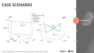
- 9. 9 CASE SCENARIO METHODOLOGY Aurelio Kaluthantrige – Ph.D. Mechanical and Aerospace Engineering – 21.02.25
- 10. 10 DATA-DRIVEN METHODS METHODOLOGY M1 M2 Aurelio Kaluthantrige – Ph.D. Mechanical and Aerospace Engineering – 21.02.25
- 11. 11 DATA-DRIVEN METHODS METHODOLOGY M1 Aurelio Kaluthantrige – Ph.D. Mechanical and Aerospace Engineering – 21.02.25 1. PREPROCESSING Input FOV Focal length Aperture Image Size Pixel size AFC 1024 256
- 12. 12 DATA-DRIVEN METHODS METHODOLOGY M1 Aurelio Kaluthantrige – Ph.D. Mechanical and Aerospace Engineering – 21.02.25 SETTINGS Parameters Epochs Processor NVIDIA V100 Tensor Core GPU Weight Keypoints 2. HIGH RESOLUTION NETWORK 256 64 26
- 13. 13 DATA-DRIVEN METHODS METHODOLOGY M1 Aurelio Kaluthantrige – Ph.D. Mechanical and Aerospace Engineering – 21.02.25 3. POST PROCESSING: COVARIANCE COMPUTATION 1024 64 26
- 14. 14 DATA-DRIVEN METHODS METHODOLOGY M1 Aurelio Kaluthantrige – Ph.D. Mechanical and Aerospace Engineering – 21.02.25 3. POST PROCESSING: FLAG DIMORPHOS 64 26
- 15. 15 DATA-DRIVEN METHODS METHODOLOGY M1 Aurelio Kaluthantrige – Ph.D. Mechanical and Aerospace Engineering – 21.02.25 3. POST PROCESSING: OUTPUT 64 26 1024 MEASUREMENTS Centroid Didymos Centroid Dimorphos (if available) Range Associated covariances
- 16. 16 DATA-DRIVEN METHODS Overview M1 M2 Parameters 28,5 M 3.6 M Weight 109 MB 13.6 MB ACT 165 9.94 Output CoM B1, CoM B2, Range from B1, covariances, Flag measurement availability COM B1, Range from B1, Sun phase angle Range measurement Derived geometrically Estimated from network METHODOLOGY Aurelio Kaluthantrige – Ph.D. Mechanical and Aerospace Engineering – 21.02.25
- 17. 17 DATASET VALIDATION Aurelio Kaluthantrige – Ph.D. Mechanical and Aerospace Engineering – 21.02.25
- 18. 18 DATASET VALIDATION DS1 DS1b DS2 DS3 DS4 DS6 DS7 DS8 DS9 Aurelio Kaluthantrige – Ph.D. Mechanical and Aerospace Engineering – 21.02.25
- 19. 19 DATASET VALIDATION DS5 Aurelio Kaluthantrige – Ph.D. Mechanical and Aerospace Engineering – 21.02.25
- 20. 20 TEST – DS1 VALIDATION NOMINAL SCENARIO Aurelio Kaluthantrige – Ph.D. Mechanical and Aerospace Engineering – 21.02.25
- 21. 21 TEST – DS2 VALIDATION PHASE ANGLE What if the Sun-asteroid-spacecraft relative position is different? Aurelio Kaluthantrige – Ph.D. Mechanical and Aerospace Engineering – 21.02.25
- 22. 22 TEST – DS3 VALIDATION SHAPE (without Dimorphos) What if the asteroid has a different shape? Aurelio Kaluthantrige – Ph.D. Mechanical and Aerospace Engineering – 21.02.25
- 23. 23 TEST – DS4 VALIDATION SHAPE (with Dimorphos) What if the asteroid has a different shape? Aurelio Kaluthantrige – Ph.D. Mechanical and Aerospace Engineering – 21.02.25
- 24. 24 TEST – DS5 VALIDATION DIFFERENT NOISE What if the noise of the captured images is different? Aurelio Kaluthantrige – Ph.D. Mechanical and Aerospace Engineering – 21.02.25
- 25. 25 TEST – DS7 VALIDATION FINE TUNING WITH CORTO How many images do I need to fine tune the algorithm to adapt for mission scenario? Aurelio Kaluthantrige – Ph.D. Mechanical and Aerospace Engineering – 21.02.25
- 26. 26 TEST – DS9 VALIDATION FINE TUNING WITH PANGU How many images do I need to fine tune the algorithm to adapt for mission scenario? Aurelio Kaluthantrige – Ph.D. Mechanical and Aerospace Engineering – 21.02.25
- 27. 27 DISCUSSION & FUTURE WORK CONCLUSION DISCUSSION 1. Different architectures behave in different ways given unseen conditions. 2. M2 slightly more accurate, more sensible to noises. 3. M1 higher inertia to fine-tuning, slower computational time. 4. M2 always converging to a solution. 5. Both methodologies performance reduced with fine-tuning. FUTURE WORK 1. Weight reduction of HRNet architecture to explore implementation on IPU. 2. Data-augmentation and image-manipulation as pre-processing steps for fine-tuning. *All datasets are publicly available to encourage other researchers to propose different approaches. Aurelio Kaluthantrige – Ph.D. Mechanical and Aerospace Engineering – 21.02.25
- 28. 21.02.25 THANK YOU! Mattia Pugliatti – Post Doc in Aerospace Engineering Mewantha.kaluthantrige-don@strath.ac.uk In/aurelio.kaluthantrige Aurelio Kaluthantrige – Ph.D. Mechanical and Aerospace Engineering Jinglang Feng – Associate Professor Jesús Gil-Fernández – GNC Engineer Francesco Topputo – Full Professor
- 29. 29 MODEL-IN-THE-LOOP TEST VALIDATION S-FUNCTION GENERATION IMPLEMENTATION IN FES OF GNC OF HERA Aurelio Kaluthantrige – Ph.D. Mechanical and Aerospace Engineering – 21.02.25
- 30. 30 PROCESSOR TEST VALIDATION DEPLOYMENT ZedBoard SD card Image Matlab drop-in function Simulink drop-in block 0 1 Host Communication lwIP Ethernet Stack Shared memory MATLAB Function Aurelio Kaluthantrige – Ph.D. Mechanical and Aerospace Engineering – 21.02.25
- 31. 31 PROCESSOR TEST VALIDATION COMPUTATIONAL TIME Arc Duration Images Average Time Aurelio Kaluthantrige – Ph.D. Mechanical and Aerospace Engineering – 21.02.25
- 32. 32 PROCESSOR TEST VALIDATION MEMORY UTILIZATION Arc Duration Images Average Time Total RAM: 264 MB Static variables from MATLAB Coder, can be largely improved Core 1 Memory .bss: 155.24 MB .data: 1.4 KB .txt: 108.95 MB Weight and biases Core 0 Memory 10 MB Shared Memory 8 MB Aurelio Kaluthantrige – Ph.D. Mechanical and Aerospace Engineering – 21.02.25
Editor's Notes
- #1: Tyvak international
- #3: 7/10
- #4: Remember to say that it takes 48 seconds
- #5: Remember to say that it takes 48 seconds
- #6: Visual based navigation technique
- #7: Visual based navigation technique
- #8: The FES is a SW environment that includes reference models of the selected GNC solutions and algorithms defined specifically for the mission, and it allows us to test the validity of the designed GNC at a SW level.
- #9: COM RANGE, (+ com 2, covariance)
- #10: The network maintains the high resolution representations of the input images by connecting multiple subnetworks in parallel. The first stage is a high-resolution subnetwork. New stages are formed from the gradual introduction of high-to-low subnetworks. To maintain the high-resolution representation, repeated multiscale fusions are performed using low-resolution representation of the same depth and level. The last high-resolution representation is then used for the regression of the selected visual data [7].
- #11: COM RANGE, (+ com 2, covariance)
- #12: The network maintains the high resolution representations of the input images by connecting multiple subnetworks in parallel. The first stage is a high-resolution subnetwork. New stages are formed from the gradual introduction of high-to-low subnetworks. To maintain the high-resolution representation, repeated multiscale fusions are performed using low-resolution representation of the same depth and level. The last high-resolution representation is then used for the regression of the selected visual data [7].
- #13: COM RANGE, (+ com 2, covariance)
- #14: COM RANGE, (+ com 2, covariance)
- #15: COM RANGE, (+ com 2, covariance)
- #16: COM RANGE, (+ com 2, covariance)
- #17: CORTO stands for Celestial Object Rendering TOol and it is an open-access tool that uses Blender to generate high-fidelity, large, annotated datasets of celestial bodies
- #18: The distribution of DS1a, DS1b, DS1c, DS3, DS4, and DS5 is characterized by random points between 10 km and 40 km from Didymos, with Sun phase angles ranging from 0◦ to 120◦, and absolute values of elevation angle with respect to Didymos’ equator between 0◦ and 30◦ Lastly, the distribution of DS2 points differs from all those described above only for one condition: the illumination conditions are adverse, with the Sun phase angles ranging from 120◦ to 150◦ These datasets mimic real mission scenarios in which a limited amount of images could be available to fine-tune a data-driven method. The eight different fine-tuned networks are then tested with DS7 and DS9 respectively, as they would be deployed in the next phase of the Hera mission, to assess the impact of the fine-tuning performed during the ECP
- #19: horizontal motion blur (νmb), a generic isotropic blur (νb), a gamma correction factor (γ), mean (νµ) and variance (νσ) of Gaussian noise are sampled with random uniform distributions according to the extremal values reported in Table 8 (note, however, that νµ and νσ are sampled in logarithmic scale)
- #20: ONNX is an open format built to represent machine learning models. The FES represents the environment where the reference models of the selected algorithms and solution for the GNC system of the Hera mission are implemented.
- #26: ONNX is an open format built to represent machine learning models. The FES represents the environment where the reference models of the selected algorithms and solution for the GNC system of the Hera mission are implemented.
- #27: or instance, working in single or fixed precision is expected to improve the computational performances with minimal impact on the accuracy and output of the network. Moreover, hardware-accelerated implementations exploiting Field Programmable Gate Array (FPGA) architectures are expected to decrease the computational time required for a single image processing by at least an or
- #28: SpaceShip Moon?
- #29: ONNX is an open format built to represent machine learning models. The FES represents the environment where the reference models of the selected algorithms and solution for the GNC system of the Hera mission are implemented.
- #30: Once the C++ sources are obtained, the zWrap toolchain3 is employed to deploy the algorithm on a ZedBoard on which the Zynq 7000 SoC was located. . The toolchain takes the source files as input and generates a boot image for the board, featuring a dualcore Asynchronous Multi-Processing (AMP) application in which the first ARM core is dedicated for socket-based communication to the host and the second core is entirely dedicated to the deployed function. Apart from the application image, the toolchain also outputs a drop-in Matlab/Simulink function and a drop-in Simulink block to run the application with inputs provided from the host, in order to seamlessly convert existing MIL simulations into Processor-In-The-Loop (PIL) simulations. A shared memory region, whose size and location is automatically inferred by the toolchain, is allocated to store the inputs and output variables
- #31: the recorded computational time registers a standard deviation of just 0.15 s, less than 0.01%
- #32: the .data section accounted for 1.43 KB. This contains non-constant, initialized variables; • the .bss section accounted for 155.24 MB and refers to the space occupied by uninitialized variables.