


![equipment. Hacking random connectors is also beyond the scope of this
document, but it can be an interesting hobby by itself.
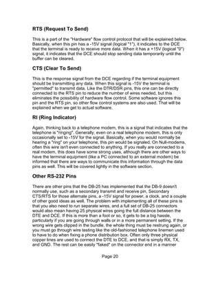
mini-stereo plug connector
This is a male mini-stereo plug connector:
Some digital cameras come with a cable that has a mini-stereo plug connector
on the end the plugs into the camera, and a DB-9 connector on the end that
plugs into the PC.
See [1]
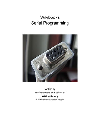
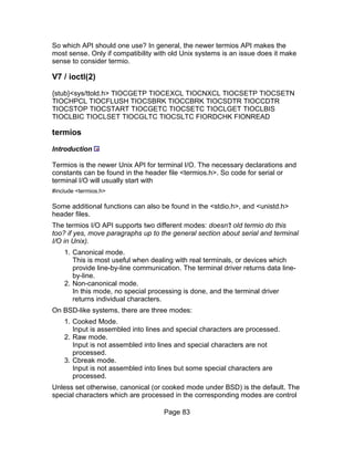
Wiring Pins Explained
The wiring of RS-232 devices involves first identifying the actual pins that are
being used. Here is how a female DB-9 connector is numbered:
If the numbers are hard to read, it starts at the top-right corner as "1", and goes
left until the end of the row and then starts again as pin 6 on the next row until
you get to pin 9 on the bottom-left pin. "Top" is defined as the row with 5 pins.
The male connector (like what you have on your PC) is simply this same order,
but reversed from right to left.
Page 17](https://image.slidesharecdn.com/serialprogramming-100823061207-phpapp02/85/Serial-Programming-17-320.jpg)

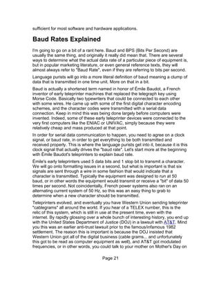


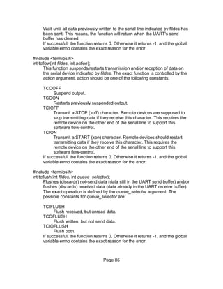
![Software I/O access
When you get down to actually using this in your software, the assembly
language instruction to send or receive data to port 9 looks something like this:
out 9, ah ; sending data from register ah out to port 9
in 9, ah ; getting data from port 9 and putting it in register ah
When programing in higher level languages, it gets a bit simpler. A typical C
language Port I/O library is usually written like this:
char test;
test = 255;
outp(9,test);
inp(9,*test);
For many versions of Pascal, it treats the I/O ports like a massive array that you
can access, that is simply named Port:
procedure PortIO(var Test: Byte);
begin
Port[9] := Test;
Test := Port[9];
end;
Warning!! And this really is a warning. By randomly accessing I/O ports in your
computer without really knowing what it is connected to can really mess up your
computer. At the minimum, it will crash the operating system and cause the
computer to not work. Writing to some I/O ports can permanently change the
internal configuration of your computer, making a trip to the repair shop
necessary just to undo the damage you've done through software. Worse yet, in
some cases it can cause actual damage to the computer. This means that some
chips inside the computer will no longer work and those components would have
to be replaced in order for the computer to work again. Damaged chips are an
indication of lousy engineering on the part of the computer, but unfortunately it
does happen and you should be aware of it.
Don't be afraid to use the I/O ports, just make sure you know what you are
writing to, and you know what equipment is "mapped" to for each I/O port if you
intend to use a particular I/O port. We will get into more of the specifics for how
to identify the I/O ports for serial communication in a bit. Finally we are starting to
write a little bit of software, and there is more to come.
x86 port I/O extensions
There are a few differences between the 8008 CPU and the 8086. The most
notable that affects software development is that instead of just 256 port I/O
addresses, the 8086 can access 65536 different I/O ports. In addition, besides
Page 30](https://image.slidesharecdn.com/serialprogramming-100823061207-phpapp02/85/Serial-Programming-30-320.jpg)

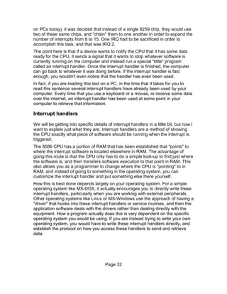


![Port[$20] := $20;
This is sending the command called "End of Interrupt" or often written as an
abbreviation simply "EOI". There are other commands that can be sent to this
register, but for our purposes this is the only one that we need to concern
ourselves with.
Now this will clear the "master" PIC, but if you are using a device that is triggered
on the "slave" PIC, you also need to inform that chip as well that the interrupt
service has been completed. This means you need to send "EOI" to that chip as
well in a manner like this:
Port[$A0] := $20;
Port[$20] := $20;
There are other things you can do to make your computer system work
smoothly, but let's keep things simple for now.
PIC Device Masking
Before we leave the subject of the 8259 PIC, I'd like to cover the concept of
device masking. Each one of the devices that are attached to the PIC can be
"turned on" or "turned off" from the viewpoint of how they can interrupt the CPU
through the PIC chip. Usually as an application developer all we really care
about is if the device is turned on, although if you are trying to isolate
performance issues you might turn off some other devices. Keep in mind that if
you turn a device "off", the interrupt will not work until it is turned back on. That
can include the keyboard or other critical devices you may need to operate your
computer.
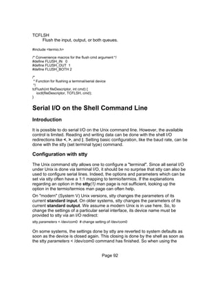
The register to set this mask is called "Operation Control Word 1" or "OCW1".
This is located at the PIC base address + 1, or for the "Master" PIC at Port I/O
Address $21. This is where you need to go over bit manipulation, which I won't
cover in detail here. The following tables show the related bits to change in order
to enable or disable each of the hardware interrupt devices:
Page 36](https://image.slidesharecdn.com/serialprogramming-100823061207-phpapp02/85/Serial-Programming-36-320.jpg)
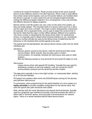
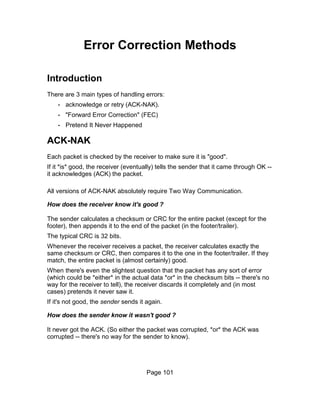
![Master OCW1 ($21)
Bit IRQ Enabled Device Function
7 IRQ7 Parallel Port (LPT1)
6 IRQ6 Floppy Disk Controller
5 IRQ5 Reserved/Sound Card
4 IRQ4 Serial Port (COM1)
3 IRQ3 Serial Port (COM2)
2 IRQ2 Slave PIC
1 IRQ1 Keyboard
0 IRQ0 System Timer
Slave OCW1 ($A1)
Bit IRQ Enabled Device Function
7 IRQ15 Reserved
6 IRQ14 Hard Disk Drive
5 IRQ13 Math Co-Processor
4 IRQ12 PS/2 Mouse
3 IRQ11 PCI Devices
2 IRQ10 PCI Devices
1 IRQ9 Redirected IRQ2 Devices
0 IRQ8 Real Time Clock
Assuming that we want to turn on IRQ3 (typical for the serial port COM2), we
would use the following software:
Port[$21] := Port[$21] and $F7; {Clearing bit 3 for enabling IRQ3}
And to turn it off we would use the following software:
Port[$21] := Port[$21] or $08; {Setting bit 3 for disabling IRQ3}
If you are having problems getting anything to work, you can simply send this
command in your software:
Port[$21] := 0;
which will simply enable everything. This may not be a good thing to do, but will
have to be something for you to experiment with depending on what you are
working with. Try not to take short cuts like this as not only is it a sign of a lazy
Page 37](https://image.slidesharecdn.com/serialprogramming-100823061207-phpapp02/85/Serial-Programming-37-320.jpg)


![registers are Read only. If you attempt to write data to them, you may end up
with either some problems with the modem (worst case), or the data will simply
be ignored (typically the result). As mentioned earlier, some registers share a
Port I/O address where one register will be used when you write data to it and
another register will be used to retrieve data from the same address.
Each serial communication port will have its own set of these registers. For
example, if you wanted to access the Line Status Register (LSR) for COM1, and
assuming the base I/O Port address of $3F8, the I/O Port address to get the
information in this register would be found at $3F8 + $05 or $3FD. Some
example code would be like this:
const
COM1_Base = $3F8;
COM2_Base = $2F8;
LSR_Offset = $05;
function LSR_Value: Byte;
begin
Result := Port[COM1_Base+LSR_Offset];
end;
There is quite a bit of information packed into each of these registers, and the
following is an explanation for the meaning of each register and the information it
contains.
Transmitter Holding Buffer/Receiver Buffer
The Transmit and Receive buffers are related, and often even use the very same
memory. This is also one of the areas where later versions of the 8250 chip have
a significant impact, as the later models incorporate some internal buffering of
the data within the chip before it gets transmitted as serial data. The base 8250
chip can only receive one byte at a time, while later chips like the 16550 chip will
hold up to 16 bytes either to transmit or to receive (sometimes both... depending
on the manufacturer) before you have to wait for the character to be sent. This
can be useful in multi-tasking environments where you have a computer doing
many things, and it may be a couple of milliseconds before you get back to
dealing with serial data flow.
These registers really are the "heart" of serial data communication, and how data
is transferred from your software to another computer and how it gets data from
other devices. Reading and Writing to these registers is simply a matter of
accessing the Port I/O address for the respective UART.
Page 40](https://image.slidesharecdn.com/serialprogramming-100823061207-phpapp02/85/Serial-Programming-40-320.jpg)


![transmitting serial data will be unpredictable, and will change from one computer
to the next, or even from one time you boot the computer to the next. This is an
error condition, and if you are writing software that works with baud rate settings
on this level you should catch potential "0" values for the Divisor Latch.
Here is some sample software to set and retrieve the baud rate for COM1:
const
COM1_Base = $3F8;
COM2_Base = $2F8;
LCR_Offset = $03;
Latch_Low = $00;
Latch_High = $01;
procedure SetBaudRate(NewRate: Word);
var
DivisorLatch: Word;
begin
DivisorLatch := 115200 div NewRate;
Port[COM1_Base + LCR_Offset] := Port[COM1_Base + LCR_Offset] or $80; {Set DLAB}
Port[COM1_Base + Latch_High] := DivisorLatch shr 8;
Port[COM1_Base + Latch_Low] := DivisorLatch and $FF;
Port[COM1_Base + LCR_Offset] := Port[COM1_Base + LCR_Offset] and $7F; {Clear DLAB}
end;
Page 43](https://image.slidesharecdn.com/serialprogramming-100823061207-phpapp02/85/Serial-Programming-43-320.jpg)
![function GetBaudRate: Integer;
var
DivisorLatch: Word;
begin
Port[COM1_Base + LCR_Offset] := Port[COM1_Base + LCR_Offset] or $80; {Set DLAB}
DivisorLatch := (Port[COM1_Base + Latch_High] shl 8) + Port[COM1_Base + Latch_Low];
Port[COM1_Base + LCR_Offset] := Port[COM1_Base + LCR_Offset] and $7F; {Clear DLAB}
Result := 115200 div DivisorLatch;
end;
Interrupt Enable Register
This register allows you to control when and how the UART is going to trigger an
interrupt event with the hardware interrupt associated with the serial COM port. If
used properly, this can enable an efficient use of system resources and allow
you to react to information being sent across a serial data line in essentially real-
time conditions. Some more on that will be covered later, but the point here is
that you can use the UART to let you know exactly when you need to extract
some data. This register has both read and write access.
The following is a table showing each bit in this register and what events that it
will enable to allow you check on the status of this chip:
Interrupt Enable Register (IER)
Bit Notes
7 Reserved
6 Reserved
5 Enables Low Power Mode (16750)
4 Enables Sleep Mode (16750)
3 Enable Modem Status Interrupt
2 Enable Receiver Line Status Interrupt
1 Enable Transmitter Holding Register Empty Interrupt
0 Enable Received Data Available Interrupt
The Received Data interrupt is a way to let you know that there is some data
waiting for you to pull off of the UART. This is probably the one bit that you will
use more than the rest, and has more use.
The Transmitter Holding Register Empty Interrupt is to let you know that the
output buffer (on more advanced models of the chip like the 16550) has finished
sending everything that you pushed into the buffer. This is a way to streamline
the data transmission routines so they take up less CPU time.
The Receiver Line Status Interrupt indicates that something in the LSR register
has probably changed. This is usually an error condition, and if you are going to
Page 44](https://image.slidesharecdn.com/serialprogramming-100823061207-phpapp02/85/Serial-Programming-44-320.jpg)


![when written in Pascal, the above algorithm ends up looking like this:
const
COM1_Addr = $3F8;
FCR = 2;
IIR = 2;
SCR = 7;
function IdentifyUART: String;
var
Test: Byte;
begin
Port[COM1_Addr + FCR] := $E7;
Test := Port[COM1_Addr + IIR];
if (Test and $40) > 0 then
if (Test and $80) > 0 then
if (Test and $20) > 0 then
IdentifyUART := '16750'
else
IdentifyUART := '16550A'
else
IdentifyUART := '16550'
else begin
Port[COM1_Addr + SCR] := $2A;
if Port[COM1_Addr + SCR] = $2A then
IdentifyUART := '16450'
else
IdentifyUART := '8250';
end;
end;
We still havn't identified between the 8250, 8250A, or 8250B; but that is rather
pointless anyway on most current computers as it is very unlikely to even find
one of those chips because of their age.
A very similar procedure can be used to determine the CPU of a computer, but
that is beyond the scope of this book.
External References
• History of Interrupt Programming
• 8259 Chip Information with other registers explained
• Interfacing the Serial / RS232 Port
Page 59](https://image.slidesharecdn.com/serialprogramming-100823061207-phpapp02/85/Serial-Programming-59-320.jpg)


![Looking up UART Base Address in RAM
We will get back to the issue of the IRQ Number in a little bit, but for now we
need to know where to start accessing information about each UART. As
demonstrated previously, DOS also keeps track of where the UART IO ports are
located at for its own purpose, so you can try to "look up" within the memory
tables that DOS uses to try and find the correct address as well. This doesn't
always work, because we are going outside of the normal DOS API structure.
Alternative operating systems like FreeDOS that are otherwise compatable with
MS-DOS may not work in this manner, so take note that this may simply give you
a wrong result altogether.
The addresses for the serial I/O Ports can be found at the following locations in
RAM:
Port Segment Offset
COM1 $0040 $0000
COM2 $0040 $0002
COM3 $0040 $0004
COM4 $0040 $0006
Those addresses are written to memory by the BIOS when it boots. If one of the
ports doesn't exist, the BIOS writes zero to the respective address. Note that the
addresses are given in segment:offset format and that you have to multiply the
address of the segment with 16 and add the offset to get to the pysical address
in memory. This is where DOS "finds" the port addresses so you can run the first
sample program in this chapter.
In assembler you can get the addresses like this:
; Data Segment
.data
Port dw 0
...
; Code Segment
.code
mov ax,40h
mov es,ax
mov si,0
mov bx,Port ; 0 - COM1 , 1 - COM2 ...
shl bx,1
mov Port, es:[si+bx]
In Turbo Pascal, you can get at these addresses almost the same way, and in
some ways even easier because it is a "high level language". All you have to do
Page 62](https://image.slidesharecdn.com/serialprogramming-100823061207-phpapp02/85/Serial-Programming-62-320.jpg)
![is add the following line to access the COM Port location as a simple array:
var
ComPort: array [1..4] of Word absolute $0040:$0000;
The reserved word absolute is a flag to the compiler that instead of "allocating"
memory, that you already have a place in mind to have the computer look
instead. This is something that should seldom be done by a programmer unless
you are accessing things like these I/O port addresses that are always stored in
this memory location.
For a complete program that simply prints out a table of the I/O port addresses
for all four standard COM ports, you can use this simple program:
program UARTLook;
const
HexDigits: array [$0..$F] of Char = '0123456789ABCDEF';
var
ComPort: array [1..4] of Word absolute $0040:$0000;
Index: Integer;
function HexWord(Number:Word):String;
begin
HexWord := '$' + HexDigits[Hi(Number) shr 4] +
HexDigits[Hi(Number) and $F] +
HexDigits[Lo(Number) shr 4] +
HexDigits[Lo(Number) and $F];
end;
begin
writeln('Serial COMport I/O Port addresses:');
for Index := 1 to 4 do begin
writeln('COM',Index,' is located at ',HexWord(ComPort[Index]));
end;
end.
Searching BIOS Setup
Assuming that the standard I/O addresses don't seem to be working for your
computer, and you havn't been able to find the correct I/O Port offset addresses
through searching RAM either, all hope is still not lost. Assuming that you have
not accedently changed these settings earlier, you can also try to look up these
numbers in the BIOS setup page for your computer. It may take some pushing
around to find this information, but if you have a conventional serial data port on
your computer, it will be there.
If you are using a serial data port that is connected via USB (common on more
recent computers), you are simply not going to be (easily) able to do direct serial
data communications in DOS. Instead, you need to use more advanced
operating systems like Windows or Linux that is beyond the scope of this
chapter. We will cover how to access the serial communications routines in
those operating systems in subsequent chapters. The basic principles we are
discussing here would still be useful to review because it goes into the basic
Page 63](https://image.slidesharecdn.com/serialprogramming-100823061207-phpapp02/85/Serial-Programming-63-320.jpg)
![UART structure.
Making modifications to UART Registers
Now that we know where to look in memory to modify the UART registers, lets
put that knowledge to work. We are also now going to do some practical
application of the tables listed earlier in the chapter 8250 UART Programming.
To start with, lets redo the previous "Hello World" application, but this time we
are going to set the RS-232 transmission parameters to 1200 baud, 7 databits,
even parity, and 2 stop bits. I'm choosing this setting parameter because it is not
standard for most modem applications, as a demonstration. If you can change
these settings, then other transmission settings are going to be trivial.
First, we need to set up some software constants to keep track of locations in
memory. This is mainly to keep things clear to somebody trying to make changes
to our software in the future, not because the complier needs it.
const
LCR = 3;
Latch_Low = $00;
Latch_High = $01;
Next, we need to set the DLAB to a logical "1" so we can set the baud rate:
Port[ComPort[1] + LCR] := $80;
In this case, we are ignoring the rest of the settings for the Line Control Register
(LCR) because we will be setting them up in a little bit. Remember this is just a
"quick and dirty" way to get this done for now. A more "formal" way to set up
things like baud rate will be demonstrated later on with this module.
Following this, we need to put in the baud rate for the modem. Looking up 1200
baud on the Divisor Latch Bytes table gives us the following values:
Port[ComPort[1] + Latch_High] := $00;
Port[ComPort[1] + Latch_Low] := $60;
Now we need to set the values for the LCR based on our desired setting of 7-2-E
for the communication setttings. We also need to "clear" the DLAB which we can
also do at the same time.
Clearing DLAB = 0 * 128
Clearing "Set Break" flag = 0 * 64
Even Parity = 2 * 8
Two Stop bits = 1 * 4
7 Data bits = 2 * 1
Port[ComPort[1] + LCR] := $16 {8*2 + 4 + 2 = 22 or $16 in hex}
Are things clear so far? What we have just done is some bit-wise arithmetic, and
Page 64](https://image.slidesharecdn.com/serialprogramming-100823061207-phpapp02/85/Serial-Programming-64-320.jpg)
![I'm trying to keep things very simple here and to try and explain each step in
detail. Let's just put the whole thing together as the quick and dirty "Hello World",
but with adjustment of the transmission settings as well:
program HelloSerial;
const
LCR = 3;
Latch_Low = $00;
Latch_High = $01;
var
ComPort: array [1..4] of Word absolute $0040:$0000;
DataFile: Text;
begin
Assign(DataFile,'COM1');
Rewrite(DataFile);
{Change UART Settings}
Port[ComPort[1] + LCR] := $80;
Port[ComPort[1] + Latch_High] := $00;
Port[ComPort[1] + Latch_Low] := $60;
Port[ComPort[1] + LCR] := $16
Writeln(DataFile,'Hello World');
Close(DataFile);
end.
This is getting a little more complicated, but not too much. Still, all we have done
so far is just write data out to the serial port. Reading data from the serial data
port is going to be a little bit trickier.
Basic Serial Input
In theory, you could use a standard I/O library and simply read data from the
COM port like you would be reading from a file on your hard drive. Something
like this:
Readln(DataFile,SomeSerialData);
There are some problems with doing that with most software, however. One
thing to keep in mind is that using a standard input routine will stop your software
until the input is finished ending with a "Enter" character (ASCII code 13 or in hex
$0D).
Usually what you want to do with a program that recieves serial data is to allow
the user to do other things while the software is waiting for the data input. In a
multi-tasking operating system, this would simply be put on another "thread", but
with this being DOS, we don't (usually) have threading capabilities, nor is it
necessary. There are some other alternatives that we do in order to get the serial
data brought into your software.
Page 65](https://image.slidesharecdn.com/serialprogramming-100823061207-phpapp02/85/Serial-Programming-65-320.jpg)
![Polling the UART
Perhaps the easiest to do besides simply letting the standard I/O routines grab
the input is to do software polling of the UART. One of the reasons why this
works is because serial communications is generally so slow compared to the
CPU speed that you can perform many tasks in between each character being
transmitted to your computer. Also, we are trying to do practical applications
using the UART chip, so this is a good way to demonstrate some of the
capabilities of the chip beyond simple output of data.
Serial Echo Program
Looking at the Line Status Register (LSR), there is a bit called Data Ready that
indicates there is some data available to your software in the UART. We are
going to take advantage of that bit, and start to do data access directly from the
UART instead of relying on the standard I/O library. This program we are going
to demonstrate here is going to be called Echo because all it does is take
whatever data is sent to the computer through the serial data port and display it
on your screen. We are also going to be configuring the RS-232 settings to a
more normal 9600 baud, 8 data bits, 1 stop bit, and no parity. To quit the
program, all you have to do is press any key on your keyboard.
program SerialEcho;
uses
Crt;
const
RBR = 0;
LCR = 3;
LSR = 5;
Latch_Low = $00;
Latch_High = $01;
var
ComPort: array [1..4] of Word absolute $0040:$0000;
InputLetter: Char;
begin
Writeln('Serial Data Terminal Character Echo Program. Press any key on the keyboard to quit.');
{Change UART Settings}
Port[ComPort[1] + LCR] := $80;
Port[ComPort[1] + Latch_High] := $00;
Port[ComPort[1] + Latch_Low] := $0C;
Port[ComPort[1] + LCR] := $03;
{Scan for serial data}
while not KeyPressed do begin
if (Port[ComPort[1] + LSR] and $01) > 0 then begin
InputLetter := Chr(Port[ComPort[1] + RBR]);
Write(InputLetter);
end; {if}
end; {while}
end.
Page 66](https://image.slidesharecdn.com/serialprogramming-100823061207-phpapp02/85/Serial-Programming-66-320.jpg)
![Simple Terminal
This program really isn't that complicated. In fact, a very simple "terminal"
program can be adapted from this to allow both sending and recieving
characters. In this case, the Escape key will be used to quit the program, which
will in fact be where most of the changes to the program will happen. We are
also introducing for the first time direct output into the UART instead of going
through the standard I/O libraries with this line:
Port[ComPort[1] + THR] := Ord(OutputLetter);
The Transmit Holding Register (THR) is how data you want to transmit gets into
the UART in the first place. DOS just took care of the details earlier, so now we
don't need to open a "file" in order to send data. We are going to assume, to
keep things very simple, that you can't type at 9600 baud, or roughly 11,000
words per minute. Only if you are dealing with very slow baud rates like 110 baud
is that going to be an issue anyway (still at over 130 words per minute of typing...
a very fast typist indeed).
Page 67](https://image.slidesharecdn.com/serialprogramming-100823061207-phpapp02/85/Serial-Programming-67-320.jpg)
![program SimpleTerminal;
uses
Crt;
const
THR = 0;
RBR = 0;
LCR = 3;
LSR = 5;
Latch_Low = $00;
Latch_High = $01;
{Character Constants}
NullLetter = #0;
EscapeKey = #27;
var
ComPort: array [1..4] of Word absolute $0040:$0000;
InputLetter: Char;
OutputLetter: Char;
begin
Writeln('Simple Serial Data Terminal Program. Press "Esc" to quit.');
{Change UART Settings}
Port[ComPort[1] + LCR] := $80;
Port[ComPort[1] + Latch_High] := $00;
Port[ComPort[1] + Latch_Low] := $0C;
Port[ComPort[1] + LCR] := $03;
{Scan for serial data}
OutputLetter := NullLetter;
repeat
if (Port[ComPort[1] + LSR] and $01) > 0 then begin
InputLetter := Chr(Port[ComPort[1] + RBR]);
Write(InputLetter);
end; {if}
if KeyPressed then begin
OutputLetter := ReadKey;
Port[ComPort[1] + THR] := Ord(OutputLetter);
end; {if}
until OutputLetter = EscapeKey;
end.
Interrupt Drivers in DOS
The software polling method may be adequate for most simple tasks, and if you
want to test some serial data concepts without writing a lot of software, it may be
sufficient. Quite a bit can be done with just that method of data input.
When you are writing a more complete piece of software, however, it becomes
important to worry about the efficiency of your software. While the computer is
"polling" the UART to see if a character has been sent through the serial
communications port, it spends quite a few CPU cycles doing absolutely nothing
at all. It also get very difficult to expand a program like the one demonstrated
above to become a small section of a very large program. If you want to get that
last little bit of CPU performance out of your software, we need to turn to
interrupt drivers and how you can write them.
Page 68](https://image.slidesharecdn.com/serialprogramming-100823061207-phpapp02/85/Serial-Programming-68-320.jpg)

![program KeyboardDemo;
uses
Dos, Crt;
const
EscapeKey = #27;
var
OldKeybrdVector: Procedure;
{$F+}
procedure Keyclick; interrupt;
begin
if Port[$60] < $80 then begin
Sound(5000);
Delay(1);
Nosound;
end;
inline($9C) { PUSHF - Push the flags onto the stack }
OldKeybrdVector;
end;
{$F-}
begin
GetIntVec($9,@OldKeybrdVector);
SetIntVec($9,Addr(Keyclick));
repeat
if KeyPressed then begin
OutputLetter := ReadKey;
Write(OutputLetter);
end; {if}
until OutputLetter = EscapeKey;
SetIntVec($9,@OldKeybrdVector);
end.
There are a number of things that this program does, and we need to explore the
realm of 16-bit DOS software as well. The 8086 chip designers had to make
quite a few compromises in order to work with the computer technology that was
available at the time it was designed. Computer memory was quite expensive
compared to the overall cost of the computer. Most of the early microcomputers
that the IBM-PC was competing against only had 64K or 128K of main CPU
RAM anyway, so huge programs were not considered important. In fact, the
original IBM-PC was designed to operate on only 128K of RAM although it did
come standard with generally up to 640K of main RAM, especially by the time
the IBM PC-XT was relesed and the market for PC "clones" turned out what is
generally considered the "standard PC" computer today.
The design came up with what is called segmented memory, where the CPU
address is made up of a memory "segment" pointer and a 64K block of memory.
That is why some early software on these computers could only run in 64K of
memory, and created nightmares for compiler authors on the 8086. Pentium
computers don't generally have this issue, as the memory model in "protected
mode" doesn't use this segmented design methodology.
Page 70](https://image.slidesharecdn.com/serialprogramming-100823061207-phpapp02/85/Serial-Programming-70-320.jpg)


![Serial ISR
This is an example of a serial ISR we can use:
{$F+}
procedure SerialDataIn; interrupt;
var
InputLetter: Char;
begin
if (Port[ComPort[1] + LSR] and $01) > 0 then begin
InputLetter := Chr(Port[ComPort[1] + RBR]);
Write(InputLetter);
end; {if}
end;
{$F-}
This isn't that much different from the polling method that we used earlier, but
keep in mind that by placing the checking inside an ISR that the CPU is only
doing the check when there is a piece of data available. Why even check the
LSR to see if there is a data byte available? Reading data sent to the UART is
not the only reason why the UART will invoke an interrupt. We will go over that in
detail in a later section, but for now this is good programming practice as well, to
confirm that the data is in there.
By moving this checking to the ISR, more CPU time is available for performing
other tasks. We could even put the keyboard polling into an ISR as well, but we
are going to keep things very simple for now.
Fifo disabling
There is one minor problem with the way we have written this ISR. We are
assuming that there is no FIFO in the UART. The "bug" that could happen with
this ISR as it is currently written is that multiple characters can be in the FIFO
buffer. Normally when this happens, the UART only sends a single interrupt, and
it is up to the ISR to "empty" the FIFO buffer completely.
Instead, all we are going to do is simply disable the FIFO completely. This can
be done using the FCR (FIFO Control Register) and explicitly disabling the FIFO.
As an added precaution, we are also going to "clear" the FIFO buffers in the
UART as a part of the initialization portion of the program. Clearling the FIFOs
look like this:
Port[ComPort[1] + FCR] := $07; {clearing the FIFOs}
Disabling the FIFOs look like this:
Port[ComPort[1] + FCR] := $00; {disabling FIFOs}
We will be using the FIFOs in the next section, so this is more a brief introduction
to this register so far.
Page 75](https://image.slidesharecdn.com/serialprogramming-100823061207-phpapp02/85/Serial-Programming-75-320.jpg)
![Working with the PIC
Up until this point, we didn't have to worry about working with the Programmable
Interrupt Controller (the PIC). Now we need to. There isn't the need to do all of
the potential instructions for the PIC, but we do need to enable and disable the
interrupts that are used by the UART. There are two PICs typically on each PC,
but due to the typical UART IRQ vector, we really only have to deal with the
master PIC.
Pic Function I/O Port Address
PIC Commands 0x20
Interrupt Flags 0x21
This adds the following two constants into the software:
{PIC Constants}
MasterPIC = $20;
MasterOCW1 = $21;
After consulting the PIC IRQ table we need to add the following line to the
software in order to enable IRQ4 (used for COM1 typically):
Port[MasterOCW1] := Port[MasterOCW1] and $EF;
When we do the "cleanup" when the program finishes, we also need to disable
this IRQ as well with this line of software:
Port[MasterOCW1] := Port[MasterOCW1] or $10;
Remember that COM2 is on another IRQ vector, so you will have to use different
constants for that IRQ. That will be demonstrated a little bit later. We are using a
logical and/or with the existing value in this PIC register because we don't want
to change the values for the other interrupt vectors that other software and
drivers may be using on your PC.
We also need to modify the Interrupt Service Routine (ISR) a little bit to work
with the PIC. There is a command you can send to the PIC that is simply called
End of Interrupt (EOI). This signals to the PIC that it can clear this interrupt signal
and process lower-priority interrupts. If you fail to clear the PIC, the interrupt
signal will remain and none of the other interrupts that are "lower priority" can be
processed by the CPU. This is how the CPU communicates back to the PIC to
end the interrupt cycle.
The following line is added to the ISR to make this happen:
Port[MasterPIC] := EOI;
Page 76](https://image.slidesharecdn.com/serialprogramming-100823061207-phpapp02/85/Serial-Programming-76-320.jpg)
![Modem Control Register
This is perhaps the most non-obvious little mistake you can make when trying to
get the UART interrupt. The Modem Control register is really the way for the
UART to communicate to the rest of the PC. Because of the way the circuity on
the motherboards of most computers are design, you usually have to turn on the
Auxiliary Output 2 signal in order for interrupts to "connect" to the CPU. In
addition, here we are going to turn on the RTS and DTS signals on the serial
data cable to make sure the equipment is going to transmit. We will cover
software and hardware flow control in a later section.
To turn on these values in the MCR, we need to add the following line in the
software:
Port[ComPort[1] + MCR] := $0B;
Interrupt Enable Register
We are still not home free yet. We still need to enable interrupts on the UART
itself. This is very simple, and for now all we want to trigger an interrupt from the
UART is just when data is recieved by the UART. This is a very simple line to
add here:
Port[ComPort[1] + IER] := $01;
Putting this together so far
Here is the complete program using ISR input:
program ISRTerminal;
uses
Crt, Dos;
const
{UART Constants}
THR = 0;
RBR = 0;
IER = 1;
FCR = 2;
LCR = 3;
MCR = 4;
LSR = 5;
Latch_Low = $00;
Latch_High = $01;
{PIC Constants}
MasterPIC = $20;
MasterOCW1 = $21;
{Character Constants}
NullLetter = #0;
EscapeKey = #27;
var
ComPort: array [1..4] of Word absolute $0040:$0000;
Page 77](https://image.slidesharecdn.com/serialprogramming-100823061207-phpapp02/85/Serial-Programming-77-320.jpg)
![OldSerialVector: procedure;
OutputLetter: Char;
{$F+}
procedure SerialDataIn; interrupt;
var
InputLetter: Char;
begin
if (Port[ComPort[1] + LSR] and $01) > 0 then begin
InputLetter := Chr(Port[ComPort[1] + RBR]);
Write(InputLetter);
end; {if}
Port[MasterPIC] := EOI;
end;
{$F-}
begin
Writeln('Simple Serial ISR Data Terminal Program. Press "Esc" to quit.');
{Change UART Settings}
Port[ComPort[1] + LCR] := $80;
Port[ComPort[1] + Latch_High] := $00;
Port[ComPort[1] + Latch_Low] := $0C;
Port[ComPort[1] + LCR] := $03;
Port[ComPort[1] + FCR] := $07; {clearing the FIFOs}
Port[ComPort[1] + FCR] := $00; {disabling FIFOs}
Port[ComPort[1] + MCR] := $0B;
{Setup ISR vectors}
GetIntVec($0C,@OldSerialVector);
SetIntVec($0C,Addr(SerialDataIn));
Port[MasterOCW1] := Port[MasterOCW1] and $EF;
Port[ComPort[1] + IER] := $01;
{Scan for keyboard data}
OutputLetter := NullLetter;
repeat
if KeyPressed then begin
OutputLetter := ReadKey;
Port[ComPort[1] + THR] := Ord(OutputLetter);
end; {if}
until OutputLetter = EscapeKey;
{Put the old ISR vector back in}
SetIntVec($0C,@OldSerialVector);
Port[MasterOCW1] := Port[MasterOCW1] or $10;
end.
At this point you start to grasp how complex serial data programming can get.
We are not finished yet, but if you have made it this far you hopfully understand
each part of the program listed above. We are going to try and stay with this one
step at a time, but at this point you should be able to write some simple custom
software that uses serial I/O.
Command Line Input
There are a number of different ways that you can "scan" the parameters that
start the program. For example, if you start a simple terminal program in DOS,
you can use this command to begin:
Page 78](https://image.slidesharecdn.com/serialprogramming-100823061207-phpapp02/85/Serial-Programming-78-320.jpg)


![characters, such as end-of-line or backspace. The full list for a particular Unix
flavour can be found in the corresponding termios man page. For serial
communication it is often advisable to use non-canonical, (raw or cbreak mode
under BSD) to ensure that transmitted data is not interpreted by the terminal
driver. Therefore, when setting up the communication parameters, the device
should also configured for raw/non-canonical mode by setting/clearing the
corresponding termios flags. It is also possible to enable or disable the
processing of the special characters on an individual basis.
This configuration is done by using the struct termios data structure, defined in
the termios.h header. This structure is central to both the configuration of a serial
device and querying its setup. It contains a minimum of the following fields:
struct termios {
tcflag_t c_iflag; /* input specific flags (bitmask) */
tcflag_t c_oflag; /* output specific flags (bitmask) */
tcflag_t c_cflag; /* control flags (bitmask) */
tcflag_t c_lflag; /* local flags (bitmask) */
cc_t c_cc[NCCS]; /* special characters */
};
It should be noted that real struct termios declarations are often much more
complicated. This stems from the fact that Unix vendors implement termios so
that it is backward compatible with termio and integrate termio and termios
behavior in the same data structure so they can avoid to have to implement the
same code twice. In such a case, an application programmer may be able to
intermix termio and termios code.
There are more than 45 different flags which can be set (via tcsetattr()) or got
(via tcgetattr()) with the help of the struct termios. The large number of flags, and
their sometimes esoteric and pathologic meaning and behavior, is one of the
reasons why serial programming under Unix can be hard. In the device
configuration, once must be careful not to make a mistake.
Opening/Closing a Serial Device
• open(2)
• close(2)
Line-Control Functions
Termios contains a number of line-control functions. These allow a more fine-
grained control over the serial line in certain special situations. They all work on
a file descriptor fildes, returned by an open(2) call to open the serial device. In
the case of an error, the detailed cause can be found in the global errno variable
(see errno(2)).
#include <termios.h>
int tcdrain(int fildes);
Page 84](https://image.slidesharecdn.com/serialprogramming-100823061207-phpapp02/85/Serial-Programming-84-320.jpg)


![/*
* Classic struct termio. More modern Unix versions
* contain additional information. Unix versions who
* support termio and termios often use the same
* structure for termio and termios, so termio
* contains the full termios data on this systems.
*/
#define NCC 8
struct termio {
int c_iflag; /* input modes */
int c_oflag; /* output modes */
int c_cflag; /* control modes */
int c_lflag; /* local modes */
char c_cc[NCC]; /* control chars */
};
• c_cc array in struct termio
• c_iflag input mode flag in struct termio
• IGNBRK
• BRKINT
• IGNPAR
• PARMRK
• INPCK
• ISTRIP
• INLCR
• IGNCR
• ICRNL
• IUCLC
• IXON
• IXANY
• IXOFF
• c_oflag output mode flag in struct termio
• OPOST
• OLCUC
• ONLCR
• OCRNL
• ONOCR
• ONLRET
• OFILL
• OFDEL
• NLDLY
• NL0
• NL1
• CRDLY
• CR0
• CR1
Page 89](https://image.slidesharecdn.com/serialprogramming-100823061207-phpapp02/85/Serial-Programming-89-320.jpg)


![The default configurations make some sense when they are used for setting up
terminal lines or dialup lines for a Unix system (and that's what they are for).
However, such default configurations are not of much use when doing some
serial communication with some other device. The correct function of the
communication program should better not depend on some operating system
configuration. Instead, the application should be self-contained and configure the
device as needed by it.
/etc/ttytab
The ttytab format varies from Unix to Unix, so checking the corresponding man
page is a good idea. If the device is not intended for a terminal (no login), then
the getty field (sometimes also called the program field, usually the 3rd field) for
the device entry should be empty. The init field (often the 4th field) can contain
an initialization command. Using stty here is a good idea. So, a typical entry for a
serial line might look like:
# Device TermType Getty Init
tty0 unknown "" "stty parameters"
/etc/ttydefs
Just some hints:
/etc/ttydefs provides the configuration as used by the ttymon program. The
settings are similar to the settings possible with stty.
ttymon is a program which is typically run under control of the Service Access
Controller (SAC), as part of the Service Access Facility (SAF).
TODO: Provide info to set up all the sac/sacadm junk.
[edit]
/etc/serial.conf
Just some hints:
A Linux-specific way of configuring serial devices using the setserial program.
tty
tty with the -s option can be used to test if a device is a terminal (supports the
termio/termios ioctl()'s). Therefore it can also be used to check if a given file
name is indeed a device name of a serial line.
echo "Enter serial device name: c"
read dev
if tty -s < "$dev"; then
Page 94](https://image.slidesharecdn.com/serialprogramming-100823061207-phpapp02/85/Serial-Programming-94-320.jpg)


![easy-to-use application and people's difficulty to understand the API's
programming model, the API is often bad-mouthed. The API is better than its
reputation and functional. But not more.
The API uses a callback mechanism to inform the programmer about newly
arriving data. It is also a good idea to study this mechanism instead of relying on
polling the port. Unlike other callback interfaces in Java (e.g. in he GUI), this one
only allows to have one listener listening to events. If multiple listeners should
listen to serial events, the one primary listener has to be implemented in a way
that it dispatches the information to other secondary listeners.
Insert simple read/write example here
SerialIO
Because of delays in Sun's releasing of JavaComm, SerialIO.com released their
own drivers and APIs over a full year before Sun Microsystems announced the
first beta of javax.comm.SerialPort. Their commercial product is the most widely
used commercial serial port communications API, and offers native libraries for
the following platforms: Windows, OS/2, Mac, Unix (Solaris, HP/UX, FreeBSD,
SGI, AIX, SCO), Linux, Alpha and mobile devices (T-Mobile ARM, EPOC32
ARM, Sharp Zaurus and Palm OS 5.2)
RxTx
Due to the fact that Sun didn't provide a reference implementation of the
JavaComm API for Linux, people developed RxTx for Java and Linux [2]. RxTx
can be used independent of the JavaComm API, or can be used as a so called
provider for the JavaComm API. In order to do the later, a wrapper called JCL is
also needed [3]. JCL and RxTx are usually packaged together with Linux/Java
distributions. So, before trying to get them separately, it is worth having a look at
the Linux distribution CD.
The latest version of RxTx is known to work on Linux, Windows, Mac OS, Solaris
and other operating systems.
There seems to be a trend to abandon the JavaComm API, and using RxTx
directly instead of via the JCL wrapper, due to Sun's limited support and
improper documentation for the JavaComm API.
See also
• Sun Java Communications API
• Java Comm Serial API How-To for Linux
• RxTx Home Page
• SerialIO Home Page
Page 98](https://image.slidesharecdn.com/serialprogramming-100823061207-phpapp02/85/Serial-Programming-98-320.jpg)
![Forming Data Packets
Just about every idea for communicating between computers involves "data
packets", especially when more than 2 computers are involved.
The idea is very similar to putting a check in an envelope to mail to the electricity
company. We take the data (the "check") we want to send to a particular
computer, and we place it inside an "envelope" that includes the address of that
particular computer.
A packet of data starts with some address information, some other transmission-
related information, followed by the raw data, and finishes up with a few more
bytes of transmission-related data (often a Adler-32 checksum ).
The accountant at the electricity company throws away the envelope when she
gets the photo. She already knows the address of her own company. Does this
mean the "overhead" of the envelope is useless ? No.
Unfortunately, there are dozens of slightly different, incompatible protocols for
data packets, because people pick slightly different ways to represent the
address information and the check data.
... gateways between incompatible protocols ...
external links
• http://intcomm.wiki.taoriver.net/moin.cgi/ProtocolMadness
• UDP
• TCP/IP
• ATM
• HTTP
• VSCP - Very Simple Control Protocol http://www.vscp.org/ "The protocol is
free"
• "Protocol Design Folklore" by Radia Perlman. Jan 15, 2001.
http://www.awprofessional.com/articles/article.asp?p=20482
• "Devices that play together, work together: UPnP defines common
protocols and procedures to guarantee interoperability among network-
enabled PCs, appliances, and wireless devices." article by Edward F
Steinfeld, EDN, 9/13/2001 http://www.reed-
electronics.com/ednmag/index.asp?layout=article&articleid=CA154802&s
pacedesc=readersChoice&rid=0&rme=0&cfd=1
• CAN bus http://computer-solutions.co.uk/ http://computer-
solutions.co.uk/gendev/can-module.htm
"CMX-MicroNet is the first system that allows TCP/IP
and other protocols to be run natively on small processors
... [including] AVR, PIC 18, M16C."
Page 99](https://image.slidesharecdn.com/serialprogramming-100823061207-phpapp02/85/Serial-Programming-99-320.jpg)


![There is nothing more annoying than not knowing if a particular misbehaviour is
caused by a failure in the serial communication with the modem, or is a problem
with the modem (usually with the commands sent to it).
Unless in the most simple case, it is suggested to use hardware handshaking
with the modem - particularly for speeds greater then 2400 bps or 9600 bps.
Therefore, the used low-level serial communication software and hardware
should support hardware handshake. If the UART supports some FIFO, like the
16550 UART, the FIFO should be enabled (both for sending and receiving data).
It is undecided if data reception via polling or via interrupts is better. If every
incoming byte raises an interrupt there are many interrupts at high
communication speeds, and, as surprising as it might sound, polling the UART
might be more efficient in such cases.
Communication as supported by a modem is usually half-duplex. Either the DTE
or the DCE talks, the other side is supposed to listen. The communication with
the modem should best be done with
• 8 Bit
• No parity
• 1 Stop bit
See the next section for speed information.
[edit]
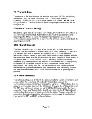
Line Speed is not DTE/DCE Speed
+-------------+ DTE/DCE speed +---------+ line speed
| DTE / |-----------------| Modem / |--------------
| Computer |-----------------| DCE |--------------
+-------------+ +---------+
An issue which can be very confusing is the difference between the line speed
(the data transfer speed on the telephone line) and the speed on the serial line
between the DTE (computer) and the DCE (modem).
First, there is always some general confusion about the line speed, because
some line speed is given with taking compression into account, while other data
is given without taking compression into account. Also, there is a difference
between bps and Baud due to the modulation schema used on the line. In
addition, marketing blurbs obscure the picture. We will not make any attempt to
clean up the long-standing Baud vs. bps confusion here (it is hopeless :-)). It is
just recommended that whenever the modem returns information about line
speed the above mentioned differences are taken into account to avoid any
misinterpretation.
Second, the speed on the telephone line does not necessarily have to be the
same as the speed on the serial line. In fact, it usually isn't on modern modems.
Page 111](https://image.slidesharecdn.com/serialprogramming-100823061207-phpapp02/85/Serial-Programming-111-320.jpg)

![prefix must be of the same case. So AT and at are acceptable, while At and aT
are not.
Flow Control
A slow device needs a way to tell its peer that currently, it is busy, so further
incoming data must be stopped until this slow device tells otherwise. This
mechanism is provided by flow control. There are two ways of doing flow control:
by hardware or software.
Hardware Flow Control
Hardware flow control is usually implemented using the CTS (Clear To Send)
and RTS (Ready to Send) lines, which needs separate hardware data lines
between devices. This is allocated in the RS-232 cable specification.
Software Flow Control
This kind of flow control doesn't need extra signal line(s) like hardware flow
control, but instead uses special control characters within the data content. To
stop further incoming data, the receiving device sends XOFF. To enable more
data, an XON will be sent.
However, since the data being sent cannot contain these characters (unless you
know that the receiving device ignores such information), binary (non-ASCII)
data cannot be transmitted this way. Software flow control is typically used for
communications to terminals and other character-based devices. Binary data
should not be sent this way as it could, randomly, contain these characters.
Hardware flow control using RTS/CTS is usually used.
Helpful Hint: Realizing that the Control Key is a special "shift" key that chops off
the 100 bit (octal), it is easy to remember that the ASCII character used for
sending XOFF is a Control-S (23 Octal) while the character for XON is a Control-
Q (21 Octal). [Think of "S" for Stop and "Q" for Qontinue... don't you spell it that
way?]
Changing State
General
Changing the state from command state to on-line state or vice versa is either
straight forward or a great mystery. This module covers the more obscure ways.
Page 113](https://image.slidesharecdn.com/serialprogramming-100823061207-phpapp02/85/Serial-Programming-113-320.jpg)

![Sync. vs. Async. Interface
X.25 Interface
AT Commands
The following list is the list of the original Hayes commands. Different modems
use slightly different commands. However, this list is supposed to be as "generic"
as possible, and should not be extended with modem specific commands.
Instead it is recommended to provide such command lists in an Appendix.
AT Command Format
Here is a summary of the format and syntax of AT commands. Please note that
most of the control characters are configurable, and the summary only uses the
default control characters.
• AT commands are accepted by the modem only when in command mode.
The modem can be forced into command mode with the [[#+++: Escape
Sequence]].
• Commands are grouped in command lines.
• Each command line must start with the #AT: Command Prefix and
terminated with #<CR>: End-of-line Character. The only exception is the
#A/: Repeat Last Command command.
• The body of a command line consists of visible ASCII characters (ASCII
code 32 to 126). Space (ASCII code 32) and ASCII control characters
(ASCII code 0 to 31) are ignored, with the exception of #<BS>: Backspace
Character, #<CAN>: Cancel Character, and #<CR>: End-of-line
Character.
• All characters preceding the #AT: Command Prefix are ignored.
• Interpretation / execution of the command line starts with the reception of
the first (and also command-line terminating) #<CR>: End-of-line
Character.
• Characters after the initial #AT: Command Prefix and before the #<CR>:
End-of-line Character are interpreted as commands. With some
exceptions, there can be many commands in one command line.
• Each of the basic commands consists of a single ASCII letter, or a single
ASCII letter with a &prefix, followed by a numeric value. Missing numeric
values are interpreted as 0 (zero).
• The following commands can't be followed by more commands on the
command line. They must always be the last commands in a command
Page 115](https://image.slidesharecdn.com/serialprogramming-100823061207-phpapp02/85/Serial-Programming-115-320.jpg)
![line. If they are followed by other commands, these other commands are
ignored. However, some of these commands take command modifiers
and it is possible that a following command is accidentally interpreted as a
command modifier. Therefore, care should be taken to not follow these
commands with any more commands on the same command line.
Instead, they should be placed in an own command line.
• #A: Answer Command
• #D: Dial Command
• #Z: Soft Reset Command
• A command line can be edited if the terminating #<CR>: End-of-line
Character has not ben entered, using the #<BS>: Backspace Character to
delete one command line character at a time. The initial #AT: Command
Prefix can't be edited/deleted (it has already been processed, because
upon reception of the #AT: Command Prefix the modem immediately
starts command line parsing and editing, but not execution).
• The modem echoes command lines and edits when #E: Command State
Character Echo Selection is on (surprise, surprise :-)).
• When echo is on, #<BS>: Backspace Characters are echoed with a
sequence of <BS> <BS> (backspace, space, backspace) to erase the last
character in e.g. a terminal program on the DTE.
• A command line can be canceled at any time before the terminating
#<CR>: End-of-line Character by sending the #<CAN>: Cancel Character.
No command in the command line is executed in this case.
• The #A: Answer Command and #D: Dial Command can also be canceled
as long as the handshake with the remote site has not been completed.
Cancelation is done by sending an additional character. In theory, it
doesn't matter which character. But care has to be taken that cancelation
is not attempted when the handshake has already completed. In this case
the modem has switched to on-line state (#Command State to On-line
State) and the character will be send to the remote side. A save way to
avoid this problem is to always use the [[#+++: Escape Sequence]]
followed by going on-hock with the #H: Hook Command Options. If the
modem is already in the on-line state, this will drop the connection. If the
modem is still in the handshake phase the first character of the [[#+++:
Escape Sequence]] will cancel the command (and the rest will be
interpreted as a normal command line, doing no harm).
• Command line execution stops when the first command in the command
line fails, or the whole command line has been executed. Every command
before the failed command has been executed. Every command after the
failed command and the failed command in the command line has not
been executed.
• There is no particular indication which command in a command line failed,
Page 116](https://image.slidesharecdn.com/serialprogramming-100823061207-phpapp02/85/Serial-Programming-116-320.jpg)


![B: Select Communication Standard
Syntax:
B[0|1] (original Hayes)
B[number] (extensions)
Description:
In original Hayes modems, it selects protocols for 300bps and 1200bps
handshake: B0 selects CCITT protocols; B1 selects Bell protocols.
Some vendors (e.g. Rockwell) extends it to limit connection speed (e.g. B15 - no
more than 28800 bps).
Result Codes:
Result Codes
Code Description
OK Speed/protocol selection succeeded
ERROR Speed/protocol selection failed
Related Commands and Registers:
• A: Answer
• D: Dial
• +MS: Speed and protocol selection
Page 125](https://image.slidesharecdn.com/serialprogramming-100823061207-phpapp02/85/Serial-Programming-125-320.jpg)

![D: Dial Command
Syntax:
D [T|P|digits|misc]
Description:
The command initiates dialing a number using pulse or tone.
Dial Modifiers:
• 0-9: Digits
• A-D, #, *: Characters for Dialing
• P: Pulse Dialing Modifier
• T: Tone Dialing Modifier
• W: Wait for Second Dial Tone
• ,: Delay
• @: Wait for Silence
• !: Flash
• ;: Return to Command State after Dialing
• DS=n: Dial Stored Telephone Number
• R: Originate Call in Answer Mode
Page 127](https://image.slidesharecdn.com/serialprogramming-100823061207-phpapp02/85/Serial-Programming-127-320.jpg)
![E: Command State Character Echo Selection
Syntax:
E[0|1]
Description:
Switches character echo on (1) or off (0) when in the command state. Given no
argument, assumes 0.
Result Codes:
Result Codes
Code Description
OK Parameter was valid
ERROR Bad number specified; must be either 0 or 1.
Page 128](https://image.slidesharecdn.com/serialprogramming-100823061207-phpapp02/85/Serial-Programming-128-320.jpg)


![M: Speaker On/Off Selection
Syntax:
M[0|1|2|3]
Description:
M0 switches the internal speaker always off.
M1 switches the internal speaker off when connected and on otherwise.
M2 switches the internal speaker always on.
M3 switches the internal speaker on when not connected or during retrains, and
off during normal connection.
Some vendors add additional modes.
Result Codes:
Result Codes
Code Description
OK Speaker mode setting succeeded.
ERROR Speaker mode setting failed.
Related Commands and Registers:
• L: Set internal speaker loudness
Page 133](https://image.slidesharecdn.com/serialprogramming-100823061207-phpapp02/85/Serial-Programming-133-320.jpg)


![Q: Result Code Display Options
Syntax:
Q[0|1]
Description:
The command allows to configure if result codes are supposed to be send to the
DTE or not.
Q
or
Q0
(default) Result codes are send to the DTE.
Q1
No result codes are send (silent mode).
Result Codes:
Result codes are only send if the option is turned on.
Result Codes
Code Description
OK Parameter was valid
ERROR Otherwise
Related Commands and Registers:'
• S14: General Bit Mapped Options Status Bit 2
Page 137](https://image.slidesharecdn.com/serialprogramming-100823061207-phpapp02/85/Serial-Programming-137-320.jpg)


![W: Negotiation Progress Message Selection
Syntax:
W[0|1|2]
Description:
The command controls the contents and format of the CONNECT message:
W
or
W0
(default). When connecting, the modem reports the DTE/DCE speed in the
CONNECT message. The speed is reported only once, upon initial set up
of the connection. Subsequent reports are disabled.
W1
When connecting, the modem reports the line speed, error correction
protocol, and the DTE/DCE speed. The data is reported only once, upon
initial set up of the connection. Subsequent reports are disabled.
W2
When connecting, the modem reports the line speed in the CONNECT
message. The data is reported only once, upon initial set up of the
connection. Subsequent reports are disabled.
Result Codes:
Result Codes
Code Description
OK if parameter was valid (0, 1, 2)
ERROR Otherwise.
Related Commands and Registers:'
• #X: Call Progress Options for selecting the details of the reporting
message.
• #S31: Bit Mapped Options Status Bits 2-3.
Page 142](https://image.slidesharecdn.com/serialprogramming-100823061207-phpapp02/85/Serial-Programming-142-320.jpg)
![X: Call Progress Options
Syntax:
X[0|1|2|3|4]
Description:
The command governs the type and verbosity of connect message responses:
X
or
X0
blind dial, no busy detect, CONNECT.
X1
blind dial, no busy detect, CONNECT xxxx.
X2
dial tone detect, no busy detect, CONNECT xxxx.
X3
blind dial, busy detect, CONNECT xxxx.
X4
full monitor, all messages, CONNECT xxxx.
where xxxx = DTE rate or DCE rate.
Note that the connect message response is a function of Wn, Xn and Vn.
Result Codes:
Result Codes
Code Description
OK Parameter was valid (0,1,2,3,4,5)
ERROR Otherwise
Related Commands and Registers:
• W: Negotiation Progress Message Selection
Page 143](https://image.slidesharecdn.com/serialprogramming-100823061207-phpapp02/85/Serial-Programming-143-320.jpg)

![Z: Soft Reset Command
Syntax:
Z (common)
Z[0|1|2|3] (US Robotics)
Description:
Soft reset is started. If modem is connected, connection is dropped. Last saved
profile is loaded from NVRAM to RAM. No more commands are read from the
command line.
US Robotics modems allow to specify number of NVRAM profile to load as
command parameter.
Result Codes:
Result Codes
Code Description
OK Soft reset succeeded.
ERROR Command failed.
Related Commands and Registers:
• &F: load profile from ROM
• &V: show current profile or profile from NVRAM
• &W: save current profile to NVRAM
Page 145](https://image.slidesharecdn.com/serialprogramming-100823061207-phpapp02/85/Serial-Programming-145-320.jpg)


![&J: Jack Type Selection (Auxiliary Relay Options)
This module is a stub. You can help Wikibooks by expanding it.
Command Description Template
Syntax:
<The syntax of the command, when necessary in EBNF>
Description:
<Description of the command, including information about the purpose and
effects>
Result Codes:
Result Codes
Code Description
Parameter was valid <description of
OK
success>
ERRO
Otherwise <description of failure>
R
Related Commands and Registers:
• <Link list of related commands and registers>
[edit]
&K: Local Flow Control Options
This module is a stub. You can help Wikibooks by expanding it.
Command Description Template
Syntax:
<The syntax of the command, when necessary in EBNF>
Description:
<Description of the command, including information about the purpose and
effects>
Result Codes:
Page 151](https://image.slidesharecdn.com/serialprogramming-100823061207-phpapp02/85/Serial-Programming-151-320.jpg)
![Result Codes
Code Description
Parameter was valid <description of
OK
success>
ERRO
Otherwise <description of failure>
R
Related Commands and Registers:
• <Link list of related commands and registers>
[edit]
&L: Line Type Selection (Dialup/Leased)
This module is a stub. You can help Wikibooks by expanding it.
Command Description Template
Syntax:
<The syntax of the command, when necessary in EBNF>
Description:
<Description of the command, including information about the purpose and
effects>
Result Codes:
Result Codes
Code Description
Parameter was valid <description of
OK
success>
ERRO
Otherwise <description of failure>
R
Related Commands and Registers:
• <Link list of related commands and registers>
[edit]
Page 152](https://image.slidesharecdn.com/serialprogramming-100823061207-phpapp02/85/Serial-Programming-152-320.jpg)
![&O: PAD Channel Selection
This module is a stub. You can help Wikibooks by expanding it.
Command Description Template
Syntax:
<The syntax of the command, when necessary in EBNF>
Description:
<Description of the command, including information about the purpose and
effects>
Result Codes:
Result Codes
Code Description
Parameter was valid <description of
OK
success>
ERRO
Otherwise <description of failure>
R
Related Commands and Registers:
• <Link list of related commands and registers>
[edit]
&Q: Communications Mode Options
This module is a stub. You can help Wikibooks by expanding it.
Command Description Template
Syntax:
<The syntax of the command, when necessary in EBNF>
Description:
<Description of the command, including information about the purpose and
effects>
Result Codes:
Page 153](https://image.slidesharecdn.com/serialprogramming-100823061207-phpapp02/85/Serial-Programming-153-320.jpg)
![Result Codes
Code Description
Parameter was valid <description of
OK
success>
ERRO
Otherwise <description of failure>
R
Related Commands and Registers:
• <Link list of related commands and registers>
[edit]
&R: RTS/CTS Options
This module is a stub. You can help Wikibooks by expanding it.
Command Description Template
Syntax:
<The syntax of the command, when necessary in EBNF>
Description:
<Description of the command, including information about the purpose and
effects>
Result Codes:
Result Codes
Code Description
Parameter was valid <description of
OK
success>
ERRO
Otherwise <description of failure>
R
Related Commands and Registers:
• <Link list of related commands and registers>
[edit]
Page 154](https://image.slidesharecdn.com/serialprogramming-100823061207-phpapp02/85/Serial-Programming-154-320.jpg)
![&S: Data Set Ready Options
This module is a stub. You can help Wikibooks by expanding it.
Command Description Template
Syntax:
<The syntax of the command, when necessary in EBNF>
Description:
<Description of the command, including information about the purpose and
effects>
Result Codes:
Result Codes
Code Description
Parameter was valid <description of
OK
success>
ERRO
Otherwise <description of failure>
R
Related Commands and Registers:
• <Link list of related commands and registers>
[edit]
&T: Test Options
This module is a stub. You can help Wikibooks by expanding it.
Command Description Template
Syntax:
<The syntax of the command, when necessary in EBNF>
Description:
<Description of the command, including information about the purpose and
effects>
Result Codes:
Page 155](https://image.slidesharecdn.com/serialprogramming-100823061207-phpapp02/85/Serial-Programming-155-320.jpg)
![Result Codes
Code Description
Parameter was valid <description of
OK
success>
ERRO
Otherwise <description of failure>
R
Related Commands and Registers:
• <Link list of related commands and registers>
[edit]
&U: Trellis Coding Options
This module is a stub. You can help Wikibooks by expanding it.
Command Description Template
Syntax:
<The syntax of the command, when necessary in EBNF>
Description:
<Description of the command, including information about the purpose and
effects>
Result Codes:
Result Codes
Code Description
Parameter was valid <description of
OK
success>
ERRO
Otherwise <description of failure>
R
Related Commands and Registers:
• <Link list of related commands and registers>
[edit]
Page 156](https://image.slidesharecdn.com/serialprogramming-100823061207-phpapp02/85/Serial-Programming-156-320.jpg)
![&V: View Configuration Profiles
This module is a stub. You can help Wikibooks by expanding it.
Command Description Template
Syntax:
<The syntax of the command, when necessary in EBNF>
Description:
<Description of the command, including information about the purpose and
effects>
Result Codes:
Result Codes
Code Description
Parameter was valid <description of
OK
success>
ERRO
Otherwise <description of failure>
R
Related Commands and Registers:
• <Link list of related commands and registers>
[edit]
&W: Write Active Profile to Memory
This module is a stub. You can help Wikibooks by expanding it.
Command Description Template
Syntax:
<The syntax of the command, when necessary in EBNF>
Description:
<Description of the command, including information about the purpose and
effects>
Result Codes:
Page 157](https://image.slidesharecdn.com/serialprogramming-100823061207-phpapp02/85/Serial-Programming-157-320.jpg)
![Result Codes
Code Description
Parameter was valid <description of
OK
success>
ERRO
Otherwise <description of failure>
R
Related Commands and Registers:
• <Link list of related commands and registers>
[edit]
&X: Synchronous Transmit Clock Source
This module is a stub. You can help Wikibooks by expanding it.
Command Description Template
Syntax:
<The syntax of the command, when necessary in EBNF>
Description:
<Description of the command, including information about the purpose and
effects>
Result Codes:
Result Codes
Code Description
Parameter was valid <description of
OK
success>
ERRO
Otherwise <description of failure>
R
Related Commands and Registers:
• <Link list of related commands and registers>
[edit]
Page 158](https://image.slidesharecdn.com/serialprogramming-100823061207-phpapp02/85/Serial-Programming-158-320.jpg)


![Result Codes
This module is a stub. You can help Wikibooks by expanding it.
[edit]
0: OK
[edit]
1: CONNECT
[edit]
2: RING
[edit]
3: NO CARRIER
[edit]
4: ERROR
[edit]
5: CONNECT 1200
[edit]
6: NO DIALTONE
[edit]
7: BUSY
[edit]
Page 161](https://image.slidesharecdn.com/serialprogramming-100823061207-phpapp02/85/Serial-Programming-161-320.jpg)
![8: NO ANSWER
[edit]
10: CONNECT 2400
[edit]
11: CONNECT 4800
[edit]
12: CONNECT 9600
[edit]
14: CONNECT 19200
[edit]
22: CONNECT 1200/75
[edit]
23: CONNECT 75/1200
[edit]
28: CONNECT 38400
[edit]
40: CARRIER 300
[edit]
44: CARRIER 1200/75
[edit]
45: CARRIER 75/1200
[edit]
Page 162](https://image.slidesharecdn.com/serialprogramming-100823061207-phpapp02/85/Serial-Programming-162-320.jpg)
![46: CARRIER 1200
[edit]
47: CARRIER 2400
[edit]
48: CARRIER 4800
[edit]
50: CARRIER 9600
[edit]
66: COMPRESSION: CLASS 5
[edit]
67: COMPRESSION: V.42BIS
[edit]
68: COMPRESSION: ADC
[edit]
69: COMPRESSION: NONE
[edit]
70: PROTOCOL: NONE
[edit]
71: PROTOCOL: ERROR-CONTROL/LAP-B
[edit]
72: PROTOCOL: ERROR-CONTROL/ LAP-B/HDX
[edit]
Page 163](https://image.slidesharecdn.com/serialprogramming-100823061207-phpapp02/85/Serial-Programming-163-320.jpg)
![73: PROTOCOL: ERROR-CONTROL/LAP-B/AFT
[edit]
74: PROTOCOL: X.25/LAP-B
[edit]
75: PROTOCOL: X.25/LAP-B/HDX
[edit]
76: PROTOCOL: X.25/LAP-B/AFT
[edit]
77: PROTOCOL: LAP-M
[edit]
78: PROTOCOL: LAP-M/HDX V.42
[edit]
79: PROTOCOL: LAP-M/AFT
[edit]
80: PROTOCOL: ALT
[edit]
91: AUTOSTREAM: LEVEL 1
[edit]
92: AUTOSTREAM: LEVEL 2
[edit]
93: AUTOSTREAM: LEVEL 3
[edit]
Page 164](https://image.slidesharecdn.com/serialprogramming-100823061207-phpapp02/85/Serial-Programming-164-320.jpg)
![S-Registers
This module is a stub. You can help Wikibooks by expanding it.
[edit]
S0: Ring to Answer After
[edit]
S1: Ring Count
[edit]
S2: Escape Sequence Character
[edit]
S3: Carriage Return Character
[edit]
S4: Line Feed Character
[edit]
S5: Backspace Character
[edit]
S6: Wait Before Blind Dialing
[edit]
S7: Wait for Carrier after Dialing
[edit]
Page 165](https://image.slidesharecdn.com/serialprogramming-100823061207-phpapp02/85/Serial-Programming-165-320.jpg)
![S8: Duration of Delay for Comma Dial Modifier
[edit]
S9: Carrier Detect Response Time
[edit]
S10: Delay Between Lost Carrier and Hang Up
[edit]
S11: Multi-Frequency Tone Duration
[edit]
S12: Escape Sequence Guard Time
[edit]
S18: Modem Test Timer
[edit]
S25: DTR Detection
[edit]
S26: RTS to CTS Interval
[edit]
S30: Inactivity Time-out
[edit]
S33: AFT Options
[edit]
S36: Negotiation Failure Treatment
[edit]
Page 166](https://image.slidesharecdn.com/serialprogramming-100823061207-phpapp02/85/Serial-Programming-166-320.jpg)
![S37: Desired DCE Line Speed
[edit]
S38: Delay Before Forced Hang up
[edit]
S44: Asynchronous Framing Technique Selection
[edit]
S46: Error-Control Protocol Selection
[edit]
S48: Enabling/Disabling Feature Negotiation
[edit]
S49: ASB buffer size lower limit
[edit]
S50: ASB buffer size upper limit
[edit]
S53: Global PAD Configuration
[edit]
S63: Leased line carrier level
[edit]
S69: Link Layer Window Size
[edit]
S70: Maximum Number of Retransmissions
[edit]
Page 167](https://image.slidesharecdn.com/serialprogramming-100823061207-phpapp02/85/Serial-Programming-167-320.jpg)
![S71: Link Layer Time-out
[edit]
S72: Loss of Flag Idle Time-out
[edit]
S73: No Activity Time-out
[edit]
S74, S75: Minimum Incoming Logical Channel Number (LCN)
[edit]
S76, S77: Maximum Incoming Logical Channel Number (LCN)
[edit]
S78, S79: Outgoing Logical Channel Number (LCN)
[edit]
S80: Packet Layer N20 Parameter
[edit]
S81: Packet Layer T20 Parameter
[edit]
S82: Break Signaling Technique
[edit]
S84: Adaptive start up negotiation (ASU)
[edit]
S85: ASU Negotiation Report
[edit]
Page 168](https://image.slidesharecdn.com/serialprogramming-100823061207-phpapp02/85/Serial-Programming-168-320.jpg)
![S86: Connection Failure Cause
[edit]
S92: MI/MIC Options
[edit]
S93: V.25bis DTE interface speed
[edit]
S94: Command Mode Selector
[edit]
S95: Negotiation Message Options
[edit]
S97: V.32 Automode V.22/V.22bis Probe Timing
[edit]
Advanced Features
Introduction
Modern consumer modems provide a number of additional features which were
originally uncommon for a modem, but became standard features over time. This
section provides an overview about how to program these features.
Page 169](https://image.slidesharecdn.com/serialprogramming-100823061207-phpapp02/85/Serial-Programming-169-320.jpg)


Serial Programming
- 1. Wikibooks Serial Programming Written by The Volunteers and Editors at Wikibooks.org A Wikimedia Foundation Project
- 3. © Copyright 2005, Wikimedia Foundation Inc. and contributing authors, All rights reserved. Permission is granted to copy, distribute and/or modify this document under the terms of the GNU Free Document License, version 1.2. A copy of this is included in the appendix entitled “GNU Free Document License”. Authors of this book include: Robert Horning Renffeh DavidCary Jhdiii HumbertoDiogenes Netch Breakpoint Insaneinside And many anonymous Wikibooks.org readers If you wish to be involved the content of this book, please visit the following internet web address: http://en.wikibooks.org/wiki/Programming%3ASerial_Data_Communications The content for this book was based on the content of the above Wikibook as of December 21st, 2005
- 5. Table of Contents Introduction and OSI Model................................................................................... 7 Introduction..................................................................................................................... 7 Why Serial Communication?.......................................................................................... 7 OSI Layered Network Communications Model..............................................................8 Software Examples..........................................................................................................9 Applications in Education............................................................................................. 10 External Links / References.......................................................................................... 10 RS-232 Connections........................................................................................... 11 Introduction................................................................................................................... 11 Data Terminal/Communications Equipment.................................................................11 Connection Types..........................................................................................................15 mini-stereo plug connector............................................................................................17 Wiring Pins Explained.................................................................................................. 17 Baud Rates Explained................................................................................................... 21 Signal Bits..................................................................................................................... 23 Relationship of Baud Rate to Maximum Distance........................................................26 External References.......................................................................................................27 8250 UART Programming................................................................................... 28 Introduction................................................................................................................... 28 8086 I/O ports................................................................................................................29 x86 Processor Interrupts................................................................................................31 8259 PIC (Programmable Interrupt Controller)............................................................ 33 Serial COM Port Memory and I/O Allocation.............................................................. 38 UART Registers............................................................................................................ 39 Software Identification of the UART............................................................................ 57 External References.......................................................................................................59 Serial DOS........................................................................................................... 60 Introduction................................................................................................................... 60 Hello World, Serial Data Version................................................................................. 60 Finding the Port I/O Address for the UART................................................................. 61 Making modifications to UART Registers....................................................................64 Basic Serial Input.......................................................................................................... 65 Interrupt Drivers in DOS...............................................................................................68 Terminal Program Revisited......................................................................................... 74 Serial Linux.......................................................................................................... 80 The Classic Unix C APIs for Serial Communication....................................................80 Serial I/O on the Shell Command Line ........................................................................ 92 System Configuration....................................................................................................95 Serial Java........................................................................................................... 96 Using Java for Serial Communication.......................................................................... 96 Forming Data Packets......................................................................................... 99 external links................................................................................................................. 99 Error Correction Methods.................................................................................. 101 Introduction................................................................................................................. 101 ACK-NAK.................................................................................................................. 101
- 6. FEC............................................................................................................................. 103 Pretend It Never Happened......................................................................................... 103 combination.................................................................................................................104 external links............................................................................................................... 104 Appendix A:Modems and AT Commands......................................................... 105 Introduction................................................................................................................. 105 Modem Programming Basics...................................................................................... 108 Flow Control............................................................................................................... 113 Changing State............................................................................................................ 113 Sync. vs. Async. Interface........................................................................................... 115 X.25 Interface.............................................................................................................. 115 AT Commands............................................................................................................ 115 Result Codes................................................................................................................161 S-Registers.................................................................................................................. 165 Advanced Features...................................................................................................... 169 GNU Free Documentation License................................................................... 170 How to use this License for your documents.............................................................. 176 Page 6
- 7. Introduction and OSI Model Introduction Welcome to the wonderful world of serial data communications. This is a part of a series of articles that will be cover many aspects of serial data communications. I am going to try and start from the beginning and follow a layered approach to working with serial data and by the time we are through we should be able to transfer just about any sort of data that you would care to send over wires between computers. Possibly even without wires (wireless data communication). There are so many aspects about this subject that sometimes it is a very hard nut to crack. I'm going to dive down and try to start with the basics and introducing the RS-232 serial data communications standard. Why Serial Communication? First of all, the basic standards that I will be describing are from the perspective of computer technology, positively ancient. Some of you reading this could perhaps find your grandparents or even great-grandparents using this protocol when they were in College. At the same time, it is so solid in concept that the reason for abandoning it should always be questioned. Indeed, there have been several other data transmission methods that have been developed since the RS-232 serial data protocol was established, but this workhorse is still widely used and seems to go through a rebirth every once in a while. When all else fails, RS-232 serial communication can be relied upon. When you are trying to get two pieces of computer equipment together, sometimes newer communications methods have hard limitations that can't be worked out due to number of connections, RF interference, distance limitations, being behind physical barriers, in sensitive areas like medical equipment where stray voltages can be a problem, or that you absolutely need to rely upon the data being transmitted. A sister protocol to RS-232, the RS-422 protocol, will even allow transmissions for several miles of cable. Serial data communication is widely implemented. While it is sometimes presumed that a PC can deal with just about any problem you want to throw at it, there are a number of electronic devices that are full of data which needs to be recorded. In part because of the age of this protocol, there are many legacy devices that have RS-232 serial data as the only access to the outside world. But even many of the latest network devices have RS-232 "console" ports to facilitate initial configuration and provide a means of troubleshooting when the network itself is broken. Because the hardware is so widely implemented and available, together with many software tools, it is also relatively cheap to develop Page 7
- 8. equipment and software to be using this system. Particularly when transmission speed isn't particularly important, but it is necessary to send data on a regular basis, RS-232 serial data is a very reasonable solution instead of a more expensive 10BASE-T TCP/IP solution, or even high-speed fibre optics. Serial data communication is also versatile. While the usual method of transmission is over copper wires between two fixed points, recently there have been some converters that transmit serial data over fibre optic lines, wireless transmitters, USB devices, and even being carried over TCP/IP networks. What is really surprising here is that all of these transmission methods are totally transparent to the device receiving or transmitting the serial data. It can also be a carrier for TCP/IP, and be used for private networks. OSI Layered Network Communications Model While serial data communication is not strictly a network communication protocol, it is still important to understand the layered communications model when dealing with any sort of communications protocols. Often people implementing serial data software have to build multiple layers of this model, even if they are not totally aware of it when they are doing it at the time. Network Layers • Application • Presentation • Session • Transport • Network • Data-Link • Physical Often serial data communication does not implement all of these different layers, and even more often these different layers are combined in the same module or even the very same function. This model was originally developed by the International Organization for Standards (ISO) in 1984 to help give a good idea of where different networking structures could be separated and intermingled. The point here is to know that you can separate different parts of communications sub-systems to help with the debugging process, and to move structures from one sub-system to another. If your software is well written using a model similar to this one, the software subroutines in layers above and below do not have to be rewritten if the module at a particular layer is changed. To achieve this you need to establish strong standards for the interface between the layers, which will be covered in other sections of these articles. For example, a web browser does not need to know if the HTML is being sent over fibre optic cables, wireless transmissions, or even over a serial data cable. Page 8
- 9. Serial Comm Layers For serial data communication, I see this layer model as more common: • Serial Data Applications • Serial Networks • Packet Challenge/Verification • Basic Serial Packets • 8250 UART processing • Raw RS-232 Signals In the case of many serial data applications, not all of these layers are implemented. Often it is just raw packets being transmitted in one direction, but sometimes even just a signal of any kind can indicate some action take place on a computer, regardless of content. It is possible to simply take the logic level of a raw RS-232 signal in your software, but at some point the data does need to be converted and the voltages involved with RS-232 can damage hardware, so this is very seldom done. Software Examples I don't want to get into a holy war over programming languages with this series of articles. For the moment, I'm going to be using Turbo Pascal and Delphi as the programming languages, if for no other reason then the fact that I am most comfortable programming in this development environment. If a good C/C++ guru would like to "translate" these routines, I would welcome that, as well as other programming languages where applicable. Serial communication is complicated enough that please avoid esoteric languages like Intercal or Malbrodge. A good BASIC implementation would be welcome, as would LISP. I'll try to avoid language-specific features and simply deal with functions in a generic sense, which a good programmer should be able to translate to the language of their choice. These articles are meant to teach you the basics of serial data communication, not to be a functioning serial data driver. Still, all code examples will be checked and sent through an actual compiler before being listed in the articles, and hopefully fully debugged. There is no one single way to accomplish these steps and tasks, so I am going to encourage a hands-on approach to dealing with software and setting up networks. While I've had quite a bit of experience in dealing with several serial data protocols (on the packet level), I am by no means the uberexpert at this. As I said earlier, I have considerable experience in dealing with communications at many levels, and I'd like to share some of my very hard-won knowledge. Page 9
- 10. Applications in Education While I am only a Software Engineer and don't have the "formal" credentials necessary for making an educational textbook, I do believe that there is much that could be taught about computer networking by students experimenting with serial data communication. The audience that I am aiming for with these articles are the High School hackers/computer geeks and undergraduate CS majors. A High School teacher that wanted to tackle a subject like this, or if you wanted to cover a special topic course in a university setting where students could get some very hands-on experience with communications protocols. Every layer of the OSI model could be demonstrated in a manner that students would learn from first-hand experiences why certain rules/systems have been implemented on the Internet, what standards documents mean, and perhaps even participate in creating standards documents. If you are a professor or High School instructor interested in using this text, I would be particularly interested in adapting this text to better suit your needs, or working with you in covering this subject. From a professional perspective, this is a topic that is seldom taught at a university, and usually only in passing when they are rushing through a whole bunch of other protocol suites. Software developers are usually introduced to this topic by having their supervisor dump a bunch of specification documents on their desk, a driver disk with API documentation, and perhaps a typically short deadline in order to get something working that should have been working sometime last year. Software developers who really understand serial data communication are worth gold, and often even these developers only learn just enough to get the immediate job done. I've also found that skills learned from developing serial data communications also translate into other projects and give a deeper understanding of just about any data transmission system. In addition to the other groups I mentioned, I am also aiming for those unfortunate software engineers who are trying to learn just about anything about this very difficult subject and don't know where to begin. Documentation about serial communication is sparse, and sometime contradictory. This doesn't have to be that complicated of a subject, and it is possible for mere mortals to be able to understand how everything works. External Links / References • Cisco explanation of the OSI model • University of Indiana / Unix Support Group explanation of OSI • ISO catalog of OSI standards Page 10
- 11. RS-232 Connections Introduction The RS-232 standard is in fact really a collection of connection standards between different pieces of equipment. This is a rather old standard, and has been revised many times over the years to accommodate changes to communications technology. A bare-bones connection will have only one wire connected between two pieces of equipment, but usually there is more. Three wires (transmit, receive, and ground) are usually the minimum recommended. A fully implemented RS-232 connection can have as many as 25 wires between each end, so obviously the "standard" is really less than standardized. Still, there are some basic usually accepted connections. Some of the early RS-232 connections were also used to connect terminal equipment to modems, so you will see information about modems mixed with general serial data communication. Some documentation can even get confusing about which type of communication they are talking about, and often it really doesn't matter. Data Terminal/Communications Equipment In the world of serial communications, there are two different kinds of equipment: • DTE - Data Terminal Equipment • DCE - Data Communications Equipment Straight Serial Connections In practice the distinction between the two pieces of equipment is really a matter of function rather than any real difference. As mentioned earlier, modems and serial communication equipment have been mixed together, this is another case of that. In this situation, the modem can be thought of as the Data Communications Equipment (DCE) and the terminal that somebody is sitting down and using is the Data Terminal Equipment. In the older days when it was common to use a timeshare computer system (pre 1980s), you would dial up a telephone, stick the handset that you would normally talk with into an acoustical modem, and that modem would be connected to a simple dumb terminal with an RS-232 cable. When we get to baud rates this will make more sense, but the typical connection speed was usually either 50 baud or 110 baud, and really fast connections going at 300 baud. As a side note, when the very first IMP's (Interconnection Message Processors) that formed the first nodes/routers of ARPAnet (the ancient predecessor of the internet), this was exactly the connection system they were using. This later gave way to other communication systems, but this was the beginning of the internet. Page 11
- 12. In a more modern setting, imagine a piece of equipment in a very dangerous place, like in a steel processing mill that measures the temperature of the rollers or other steel processing equipment. This would also be a form of what we now refer to as a piece of "Data Communication Equipment" that we would also want to be able to control remotely. The PC that is used in a control room of the mill would be the Data Terminal Equipment. There are many other similar kinds of devices, and RS-232 connections can be found on all kinds of equipment. The reason this is called a "straight" connection is because when the cabling is put together, each wire on each end of the connection is put to the same pin. This wiring system will be explained further on. Null Modems Often you don't always want to connect a piece of equipment to a computer, but you would also like to connect two computers together. Unfortunately, when connecting two computers with a "straight" serial connection, the two computers are fighting each other on the same wires. One way to make this work is to connect the two computers to each other with a pair of modems. As explained earlier, this is a very common task, and in the 1980's and early 1990's it was common to have "Bulletin Board Systems" (BBS) where computers would call each other up with modems and exchange all sorts of information. Now imagine if these two computers are in the very same room. Instead of going through the physical modems, they go through a "null modem", or a modem that really doesn't exist. In order to make this work you have to "cross" some of the wires so when you transmit some information on one end, the other computer is able to detect and receive that same information. In addition to simply allowing a computer to communicate and transmit data to another computer, a null modem connection can be used to "simulate" the behavior of DCE equipment. This will be particularly important later on with some of the discussion in this series of articles, where you can experiment with writing some of your own serial communication software. In my own experience, I've had to write these "emulators" in many instances, either because the equipment that I was trying to communicate with wasn't finished, or it was difficult to obtain a sample of that equipment and all that I had available to me was the communication protocol specification. Loopback Connectors Sometimes instead of trying to communicate with another computer, you would like to be able to test the transmission equipment itself. One practical way of doing this is to add a "loopback" connector to the terminal device, like a PC with a serial data connection. This connector has no cable attached, but loops the Page 12
- 13. transmit lines to the receive lines. By doing this, you can simulate both the transmission and receiving of data. Generally speaking, this is only done for actually testing the equipment, but can be used for testing software components as well. When this sort of connector is used, you will receive every byte that you transmit. If you separate out the transmission subroutines from the data capture subroutines, it can provide a controlled system for testing your application. Protocol Analyser General When it starts to get very difficult to examine the serial data being transmitted by the equipment, sometimes it is nice to be able to take a "snapshot" of the information being transmitted. This is done with a protocol analyser of one kind or another. What is done is a modification of the cabling that allows for a third computer to be able to simply read the data as it is being transmitted. Sometimes the communication protocol can get so complicated that you need to see the whole exchange, and it needs to be examined in "real-time" rather than going through some sort of software debugger. Another purpose of this is to examine the data exchange for purposes of doing some reverse engineering if you are trying to discover how a piece of equipment works. Often, despite written specifications, the actual implementation of what is occurring when transmitting data can be quite a bit different than what was originally planned. Basically, this is a powerful tool for development of serial communications protocols and software, and should not be ignored. There are common ways to connect a protocol analyser, which are discussed in the following sections. Y "Cable" A Y "Cable" is not just some cable, but also contains electronic - at least if it is not a cheap junk cable. It is supposed to be placed in between a serial line and it mirrors all signals on a third connector. This third connector can then be connected to a protocol analyser (e.g. a PC with some display software): +-----+ serial +---------+ serial +-----+ | DTE |----------| Y Cable |----------| DCE | +-----+ +---------+ +-----+ | | +----------+ | Analyser | +----------+ Page 13
- 14. It is highly recommended to not use a passive Y cable. Such a cable overloads the transmitters at the DTE and DCE, which might result in the destruction of the transmitters. Often, the line going to the analyser is also just a serial line, and the Analyser is a PC with a serial interface and some display software. The disadvantage of such a simple Y cable solutions is that it only supports half-duplex communication. That is, only one site (DTE or DCE) can talk at any time. The reason for this is that the two TX lines from the DTE and DCE are combined into one TX line going to the analyser. If the DTE and the DCE both send at the same time, their signals get mixed up on the third line going to the analyser, and the analyser probably doesn't see any decodable signal at all. See http://www.mmvisual.de/fbintermdspy.htm for an example of some simple circuitry for a Y cable. More advanced Y cable solutions provide the TX data from the DTE and DCE separately to the analyser. Such analysers are capable of displaying full-duplex communication. Advanced professional systems not only display the decoded digital information, but also monitor the analog signal levels and timing. Man-in-the-Middle In this scenario the analyser sits in the middle between the DTE and DCE. It is basically some device (e.g. a PC) with two serial interfaces. The analyser mirrors each signal from one site to the other site, and also displays the traffic. +-----+ serial +----------+ serial +-----+ | DTE |----------| Analyser |----------| DCE | +-----+ +----------+ +-----+ In principle, a simple version of such an analyser can be built with any PC with two serial interfaces. All that is needed is some software, which is not too difficult to write. Such a device will, however, lack a convenient feature. Professional analysers are able to auto-sense the speed of the serial communication. A home made solution needs to be configured to match the speed of the serial communication. Professional devices are also optimized to ensure minimal delay in the circuitry. Also, a simple homegrown, PC-based analyser can't be used to analyse faults due to signal voltage level problems. Nevertheless, any kind of protocol analyser is much better than nothing at all. Even the most simple analyser is very useful. Others See Setting up a Development Environment (for modem development) for some more information. Page 14
- 15. Breakout Box An RS232 breakout box (a BOB) is a rather nifty piece of hardware which usually combines a number of functions into one. It basically consist of two RS232 connectors, and a patch field (or switches) which allows to change the wiring between the connectors. A patch field and small pieces of wires are preferable over (DIP) switches alone, since the patch field allows access to the signals for other purposes, too. A breakout box is very useful if the pinout (DTE/DCE) of a particular device is not known. The patch field allows to quickly change the wiring from a straight connection to a null modem connection, or to set up a loopback connection. Since the patch field provides access to all signals it also allows to use the breakout box to connect a protocol analyser. Better breakout boxes also provide some signal level information on their own, by having LEDs who inform about the signal voltage. This information is useful when trying to identify an unknown pinout. High-end BOBs contain circuitry to measure ground potential difference and pulse traps circuitry to find signal glitches. Commercial breakout boxes are available in many varieties. It is also possible to build a useful BOB from a handful of simple parts on a circuit board. The patch field can be made from DIL IC sockets, and the wiring of the LEDs is simple if 2- pin dual-color LEDs are used. Each signal line should be connected via such an LED and a 680 Ohm resistor in serial to GND (Signal Ground). The home-made breakout-box is completed with a couple of RS232 connectors, possibly also one to attach a protocol analyser and some simple metal or plastic case. Connection Types If you wanted to do a general RS-232 connection, you could take a bunch of long wires and solder them directly to the electronic circuits of the equipment you are using, but this tends to make a big mess and often those solder connections tend to break and other problems can develop. To deal with these issues, and to make it easier to setup or take down equipment, some standard connectors have been developed that is commonly found on most equipment using the RS-232 standards. These connectors come in two forms: A male and a female connector. The female connector has holes that allow the pins on the male end to be inserted into the connector. Page 15
- 16. "DB-9" This is a female "DB-9" connector (properly known as DE9F): The female DB-9 connector is typically used as the "plug" that goes into a typical PC. If you see one of these on the back of your computer, it is likely not to be used for serial communication, but rather for things like early VGA or CGA monitors (not SVGA) or for some special control/joystick equipment. And this is a male "DB-9" connector (properly known as DE9M): This is the connector that you are more likely to see for serial communications on a "generic" PC. Often you will see two of them side by side (for COM1 and COM2). Special equipment that you might communicate with would have either connector, or even one of the DB-25 connectors listed below. DB-25 This is a female DB-25 connector (also known as DB25F): This is what you normally find on the end of a traditional parallel printer cable on a PC. This connector type is also used frequently for equipment that conforms to RS-232 serial data communication as well, so don't always assume if you see one of these connectors that it is always parallel. When the original RS-232 specification was written, this was originally the kind of connector that was intended, but because many of the pins were seldom if ever used, it was switched to the DB-9 connectors on more recent equipment like the original IBM-PC (yes, that is comparatively recent equipment for this standard). This is a male DB-25 connector (also known as DB25M): Male DB-25 connectors are usually used on a PC for parallel data communication, which is beyond the scope of this series of articles. However, you should still be aware that this connector is also used for serial communications on many different types of equipment. In fact, if you have a random piece of equipment that you are trying to see how it works, you can presume that it is a piece of serial Page 16
- 17. equipment. Hacking random connectors is also beyond the scope of this document, but it can be an interesting hobby by itself. mini-stereo plug connector This is a male mini-stereo plug connector: Some digital cameras come with a cable that has a mini-stereo plug connector on the end the plugs into the camera, and a DB-9 connector on the end that plugs into the PC. See [1] Wiring Pins Explained The wiring of RS-232 devices involves first identifying the actual pins that are being used. Here is how a female DB-9 connector is numbered: If the numbers are hard to read, it starts at the top-right corner as "1", and goes left until the end of the row and then starts again as pin 6 on the next row until you get to pin 9 on the bottom-left pin. "Top" is defined as the row with 5 pins. The male connector (like what you have on your PC) is simply this same order, but reversed from right to left. Page 17
- 18. Here are what each pin is usually defined as: 9-pin 25-pin pin definition 1 8 DCD (Data Carrier Detect) 2 3 RX (Receive Data) 3 2 TX (Transmit Data) 4 20 DTR (Data Terminal Ready) 5 7 GND (Signal Ground) 6 6 DSR (Data Set Ready) 7 4 RTS (Request To Send) 8 5 CTS (Clear To Send)) 9 22 RI (Ring Indicator) One thing to keep in mind when discussing these pins and their meaning, is that they are very closely tied together with modems and modem protocols. Often you don't have a modem attached in the loop, but you still treat the equipment as if it were a modem on a theoretical level. The following are more formal explanations regarding each signal: DCD (Data Carrier Detect) This is a signal to indicate from the communications equipment (DCE) that the phone line is still "connected" and receiving a carrier signal from the modem at the other end. Presumably well-written software or serial equipment could detect from this logic state when the telephone has been "hung up" on the other end. Null-modems often tie DCD to DSR at each end since there is no carrier signal involved. This signal pin can be independently detected by software, and a "real" hacker could have some fun playing with this pin to add some sort of signal to increase bandwidth. Still, it isn't worth the effort, when there are much better ways to increase data throughput. RX (Receive Data) This is the "heart" of serial data communications. This wire will have a series of alternating +15V and -15V signals that determine what the actual data is that is coming over the wire. This is the data that is incoming from the data communications equipment (or being transmitted by the DCE). Remember, when you are making devices that attach to a serial comm port, the thinking is somewhat reversed. Think more along the lines of "Terminal Receive" and it helps to keep things in the proper frame of mind. Page 18
- 19. TX (Transmit Data) The reverse of RX, this is where the terminal equipment (DTE) is transmitting serial data, using the same format and protocol that the receiver is expecting...usually. More on the exact protocol further below. Like RX, think along the lines of "Terminal Transmit" when designing equipment that will be using this pin. DTR (Data Terminal Ready) Basically a signal from the DTE that says "Hello!, I'm ready if you are". This is a general indicator to the DCE that the terminal is ready to start sending and receiving data. If there is some initialization that needs to happen in the communications equipment, this is a way for the terminal equipment to "boot" the receiving equipment. GND (Signal Ground) This is an interesting pin to look at. What it does is try to make a common "ground" reference between the equipment that is being connected to compare the voltages for the other signals. Normally this is a good thing, because sometimes different pieces of equipment have different power supplies and are some distance away. The not so pleasant thing about this wire is that it usually is a physical piece of copper that can conduct electricity that is not normally supposed to go down the wire, like a short-circuit or worse yet a bolt of lightning (it happens far more often that you would normally think for this sort of equipment). That can fry both the DCE as well as the DTE. Things like fiber converters and ground isolators can help prevent this from happening, but can still be something to worry about. Over short distances this is generally not a problem. DSR (Data Set Ready) This is the counterpart to DTR with the communications equipment (or computer peripheral on the serial line). When the DTR is sent as a signal, the communications equipment should change this signal to -15V to indicate that it is ready to communicate as well. If the DCE goes through a "boot" sequence when the DTR gets signaled, it should not signal DSR until it is complete. But many connectors "hard wire" this pin to be directly connected to the DTR pin at each end to reduce the number of wires needed in the cable. This can be useful for connecting devices using existing telephone wires, but prevents applications from using the DTR and DSR for handshaking. Page 19
- 20. RTS (Request To Send) This is a part of the "Hardware" flow control protocol that will be explained below. Basically, when this pin has a -15V signal (logical "1"), it indicates to the DCE that the terminal is ready to receive more data. When it has a +15V (logical "0") signal, it indicates that the DCE should stop sending data temporarily until the buffer can be cleared. CTS (Clear To Send) This is the response signal from the DCE regarding if the terminal equipment should be transmitting any data. When this signal is -15V the terminal is "permitted" to transmit data. Like the DTR/DSR pins, this one can be directly connected to the RTS pin to reduce the number of wires needed, but this eliminates the possibility of hardware flow control. Some software ignores this pin and the RTS pin, so other flow control systems are also used. That will be explained when we get to actual software. RI (Ring Indicator) Again, thinking back to a telephone modem, this is a signal that indicates that the telephone is "ringing". Generally, even on a real telephone modem, this is only occasionally set to -15V for the signal. Basically, when you would normally be hearing a "ring" on your telephone, this pin would be signaled. On Null-modems, often this wire isn't even connected to anything. If you really are connected to a real modem, this does have some strong uses, although there are other ways to have the terminal equipment (like a PC connected to an external modem) be informed that there are ways to communicate this information through the data pins as well. This will be covered lightly in the software section. Other RS-232 Pins There are other pins that the DB-25 has implemented that the DB-9 doesn't normally use, such as a secondary transmit and receive pin, Secondary CTS/RTS for those alternate pins, a -15V signal for power, a clock, and a couple of other good ideas as well. The problem with implementing all of these pins is that you also need to run separate wires, and a full set of DB-25 connectors would also mean having 25 physical wires going the full distance between the DTE and DCE. If this is more than a foot or so, it gets to be a big hassle, particularly if you are going through walls or in a more permanent setting. If the wrong wire gets clipped in the bundle, the whole thing must be restrung again, or you must go through wire testing like the old-fashioned telephone linemen used to have to do when fixing a phone distribution box. Often only three physical copper lines are used to connect the DTE to DCE, and that is simply RX, TX, and GND. The rest can be easily "faked" on the connector end in a manner Page 20
- 21. sufficient for most software and hardware applications. Baud Rates Explained I'm going to go on a bit of a rant here. Baud and BPS (Bits Per Second) are usually the same thing, and originally it really did mean that. There are several ways to determine what the actual data rate of a particular piece of equipment is, but in popular marketing literature, or even general reference texts, they will almost always refer to "Baud Rate", even if they are referring to bits per second. Language purists will go into a more literal definition of baud meaning a clump of data that is transmitted in one time unit. More on that in a bit. Baud is actually a shortened term named in honor of Émile Baudot, a French inventor of early teleprinter machines that replaced the telegraph key using Morse Code. Basically two typewriters that could be connected to each other with some wires. He came up with some of the first digital character encoding schemes, and the character codes were transmitted with a serial data connection. Keep in mind this was being done largely before computers were invented. Indeed, some of these early teleprinter devices were connected to the very first computers like the ENIAC or UNIVAC, simply because they were relatively cheap and mass produced at that point. In order for serial data communication to happen, you need to agree on a clock signal, or baud rate, in order to get everything to be both transmitted and received properly. This is where the language purists get into it, because it is this clock signal that actually drives the "baud rate". Let's start more at the beginning with Émile Baudot's teleprinters to explain baud rate. Émile's early teleprinters used 5 data bits and 1 stop bit to transmit a character. We will go onto formatting issues in a second, but what is important is that six signals are sent through a wire in some fashion that would indicate that a character is transmitted. Typically the equipment was designed to run at 50 baud, or in other words the equipment would transmit or receive a "bit" of data 50 times per second. Not coincidentally, French power systems also ran on an alternating current system of 50 Hz, so this was an easy thing to grab to determine when a new character should be transmitted. Teleprinters evolved, and eventually you have Western Union sending teleprinter "cablegrams" all around the world. If you hear of a TELEX number, this is the relic of this system, which is still in use at the present time, even with the internet. By rapidly glossing over a whole bunch of interesting history, you end up with the United States Department of Justice (DOJ) in a lawsuit with AT&T. Mind you this was an earlier anti-trust lawsuit prior to the famous/infamous 1982 settlement. The reason this is important is because the DOJ insisted that Western Union got all of the digital business (cable grams... and unfortunately this got to be read as computer equipment as well), and AT&T got modulated frequencies, or in other words, you could talk to your mother on Mother's Day on Page 21
- 22. their equipment. When computers were being built in the 1950s, people wanted some way to connect different pieces of computer equipment together to "talk" to each other. This finally resulted in the RS-232 standard that we are discussing on this page. While Western Union was permitted to carry digital traffic, often the connections weren't in or near computer centers. At this time AT&T found a loophole in the anti-trust settlement that could help get them into the business of being a "carrier" of computer data. They were also offering to transmit computer data at rates considerably cheaper than Western Union was going to charge. Hence, the modem was born. Modems Explained The long description of a modem is a "Modulator/Demodulator", and this description is important. Since AT&T could only carry "tones", like music from a radio network or the voice of your mother, they created a device that would electronically create "music" or "tones" that could be carried on their network. They would then take a computer "1" or "0" and "modulate" the bit to a frequency, like say 2600 Hz. (The exact tones varied based on baud rate and other factors, but there were exact frequency specs here.) A matching device would be able to look for that "note" or "tone" in the "music" and be able to convert that back to a computer "1" or "0", or in other words, demodulate the music. Since all you and your buddy on each end of the telephone are only playing music to each other, it was legal for AT&T to have that music on their network. That only computers could possibly understand this music is besides the point, and the DOJ turned a blind eye on the whole practice, despite objections from Western Union. The original modems you could buy were AT&T Bell 103 modems. These were clunky boxes about the size of a shoe box that had a bunch of switches on the outside and an RS-232 cable that connected to the computer equipment you were using. See, the RS-232 keeps coming back, so we are making some progress here. These boxes were designed for the old-fashioned handset telephones and had pieces of rubber that would go around the "speaker" and "mike" portion of the telephone (no direct copper connection to the telephone equipment back then). If you wanted to dial the telephone, you had to use the rotary dial on the phone itself... the computer didn't have access to that sort of equipment. Keep in mind that the FCC regulated just about everything that happened with phone equipment, and AT&T owned everything related to telephones. You even had to "rent" the modem from AT&T, and that rental charge was on your monthly phone bill. The Bell 103 was originally 110 baud, although it eventually had a switch to "move up" to 220 baud. 300 baud modems were also fairly common throughout the 1960's and 1970's. Keep in mind that AT&T (or your local phone company) was the only company you could even rent a modem from, whether you wanted Page 22
- 23. one or not. By 1982, modems were so commonly used and the POTS telephone network so widespread that this same system of sending "music" over the telephone has been preserved, even though the legal reasons for doing it are no longer valid. With the advent of ISDN and DSL lines, this is no longer the case and the phone companies are now sending pure digital signals instead. This is also why DSL lines can carry much more data than an ordinary phone line, even though it is the same pair of copper wires going into your home. When modems started going to very high speeds, they hit a brick wall of sorts. It was decided back in the 1950's that telephone equipment would only have to carry tone signals going to about 10kHz. For normal voice conversations this is sufficient, and you can even tell the difference between a man and a woman on the telephone. The problem comes in that this means the highest normal "baud rate" that you can send over a home telephone network is about 9600 baud, usually about 4800 baud, because the telephone equipment itself is going to be dropping "bits" as you switch from one tone to another. Without going into the heavy math, you need to have at least one full "sound wave" in order to be able to distinguish one tone or note from another. Modem manufacturers did think of something else that could be done to overcome this limitation, however. Instead of just sending one tone at a time, you could play a whole "chord", or several distinct tones at the same time. Finally back to baud vs. bits per second. With higher speeds, instead of simply sending only one bit, you are sending two or as many as sixteen bits at the same time with varying "chords" of "music". This is how you get a 56K BPS modem, even though it is still only transmitting at 9600 baud. Get it now? Signal Bits There are four sets of transmission bits that are used in the RS-232 standard. The positioning of these bits in the RS-232 data stream is all that distinguishes one bit from the other. This is also where serial communication really hits the "metal", because each bit follows in a sequence, or in a serial fashion. All of the other wires, pins, baud rate, and everything else is to make sure that these bits can be understood. Keep in mind that at this point the entire protocol is based on the transmission of a single character. Multiple characters can be sent, but they are a sequence of single character transmission events. How the characters relate is based on what the software does with the data on the next protocol "layer". Start Bit When a transmission line is not sending anything, it remains in a logical state of "1", or -15V on the wire. When you want to send a character, you start by changing the voltage to +15V, indicating a logical "0" state. Each subsequent bit is based on the baud rate that is established for communication between each Page 23
- 24. device. This bit signals that the receiving device should start scanning for subsequent bits to form the character. Data Bits This is the primary purpose of serial communications, where the data actually gets sent. The number of bits here can vary quite a bit, although in current practice the number of bits typically transmitted is eight bits. Originally this was five bits, which was all that the early teleprinters really used to make the letters of the Alphabet and a few special characters. This has implications for internet protocols as well, because early e-mail systems transmitted with only seven bits when they were connected over some RS-232 links. This worked because the early character encoding schemes, mainly ASCII, only used seven bits to encode all characters commonly used for the English language. Because computer components work best on powers of 2 (2,4,8,16,32, etc.), eight bits became more commonly used for data storage of individual characters. Unicode and other coding schemes have moved this concept forward for languages other than English, but eight bits still is a very common unit for transmitting data, and the most common setting for RS-232 devices today. The least significant bit (LSB) is transmitted first in this sequence of bits to form a character. Parity Bit To help perform a limited error check on the characters being transmitted, the parity bit has been introduced. It is useful, but you must understand that there are limits to what information can be stored in a single bit. The "formula" that is used to determine the value of the parity bit is to add up the number of bits sent as a "1" in the string of data bits. There are four different kinds of parity configuration to consider: Odd Parity When the sum of bits ends up coming up with an odd number (like the sequence 01110110), this bit will be set to a logical state of "1". Even Parity This uses the formula of trying to determine if there are an even number of bits set to "1". In this regard, it is the exact opposite state of the Odd Parity. Mark Parity Using this concept, the transmission protocol is essentially ignoring the parity bit entirely. Instead, the transmission configuration is sending a logical "1" at the Page 24
- 25. point that a parity bit should be sent, regardless of if the sequence should have an odd or even count. This configuration mode is useful for equipment that may want to be testing parity checking software or firmware in the receiving equipment. Space Parity The opposite of Mark parity, this sends a logical "0" for the parity checksum. Again, very useful for equipment diagnostics. Parity None This isn't really a parity formula, but rather an acknowledgement that parity really doesn't work, so the equipment doesn't even check for it. This means the parity bit isn't even used. This can cause, in some circumstances, a slight increase in the total data throughput. More on that below. Stop Bits This really isn't a bit at all, but an agreement that once the character is sent that the transmitting equipment will return to a logical "1" state. The RS-232 specification requires this logical state of "1" to remain for at least one whole clock cycle, indicating that the character transmission is complete. Sometimes the protocol will specify two stop bits. One reason that this might be done is because the clock frequencies being used by the equipment might have slightly different timing, and over the course of hundreds or thousands of characters being transmitted the difference between two clocks on the two different pieces of equipment will cause the expected bits to be shifted slightly, causing errors. By having two stop bits the transmission is slightly slower, but the clock signals between the two pieces of equipment can be coordinated better. Equipment expecting one stop bit can accept data transmitted by equipment sending two stop bits. It won't work the other way around, however. This is something to try if you are having problems trying to get two pieces of equipment to communicate at a given baud rate, to add the second stop bit to the transmitter. Data Transmission Rates We got into a discussion of baud rate vs. bits per second. Here is where baud as the number of bits being transmitted is still off, even if the nominal bits per second is also the same as the baud rate. By adding start bits, stop bits, and parity bits, that is going to add overhead to the transmission protocol. All digital transmission protocols have some sort of overhead on them, so this shouldn't be that much of a surprise. As we get more into data packets and other issues, the actual amount of data being transmitted will drop even further. Keep in mind that if you are transmitting with 6 data bits, 2 Stop bits, and Even Page 25
- 26. Parity, you are transmitting only six bits of data and four other bits of data. That means that even with 9600 baud, you are only transmitting 5,760 bits of data per second. That really is a big difference, and that is still only raw bits once it gets through the actual serial communications channel. A more typical 8 data bits, 1 Stop Bit, No Parity will be a little bit better at 9600 baud, with eight bits of data and only two bits used for overhead. That gives a total throughput of 7,680 bits per second. A little bit better, but you can't simply presume that the baud rate indicates how much data is going to be transmitted. Relationship of Baud Rate to Maximum Distance There is one final topic that you should keep in mind when you are doing serial communication over RS-232. There are some hard physical limits to how far serial data communication can occur over a piece of wire. When you apply a voltage onto a wire it takes some time for that voltage to go down the full length of the wire and there are other unstable conditions that happen when you send a "pulse" down the wire and change voltages too quickly. This problem is worse as wires become longer and the frequency (i.e. baud rate) increases. This distance can vary based on a number of factor, including the thickness of the wires involved, RF interference on the wires, quality of the wires during the manufacturing process, how well they were installed... e.g., are there any "kinks" in the wires that force it into a sharp bend, and finally the baud rate that you are transmitting the data. This table presumes a fairly straight and uniform cable that is typical for most low-voltage applications (i.e., not a power circuit that uses 110V to run your refrigerator, toaster, and television). Typically something like a CAT-5 cable (also used for local networks or phone lines) should be more than sufficient for this purpose. Baud Rate Maximum Distance (in feet) 2400 3000 4800 1000 9600 500 19200 50 You should also be aware that there are ways to get around this limitation. There are "short haul modems" that can extend this distance to several miles of cable. There are also telephone lines, or conventional modems, and other long- distance communications techniques. I am not going to cover any details beyond simply letting you know that there are other ways to handle data in situations like this, and that those signals can be converted to simple RS-232 data formats that a typical home computer can interpret. Distance still can be a limiting factor for Page 26
- 27. communication, although when you are talking about distances like to Saturn for the Cassini mission, serial data communication has other issues involved than just data loss due to cable length. And yes, NASA/ESA is using serial data communication for transmitting those stunning images back to Earth. External References • TIA-574 Specification • RS-232 wiring standards explained • RS-232 connection types explained • Wikipedia article on RS-232 • RS-232 standards explained by HW-Server • Serial Pinouts (D25 and D9 Connectors) (also has more technical information about the UARTs used in PCs) • RS232 Connections, and wiring up serial device has several diagrams, including one showing how to let one PC monitor the serial communication between 2 other RS232 devices. • Lammert Bies, RS232 Specifications and standard Includes technical specs on RS-232 signals and more detailed information about parity checking. Page 27
- 28. 8250 UART Programming Introduction Finally we are moving away from wires and voltages and hard-core electrical engineering applications, although we still need to know quite a bit regarding computer chip architectures at this level. While the primary focus of this section will concentrate on the 8250 UART, there are really three computer chips that we will be working with here: • 8250 UART • 8259 PIC (Programmable Interrupt Controller) • 8086 CPU (Central Processing Unit) Keep in mind that these are chip families, not simply the chip part number itself. Computer designs have evolved quite a bit over the years, and often all three chips are put onto the same piece of silicon because they are tied together so much, and to reduce overall costs of the equipment. So when I say 8086, I also mean the successor chips including the 80286, 80386, Pentium, and compatible chips made by manufacturers other than Intel. There are some subtle differences and things you need to worry about for serial data communication between the different chips other than the 8086, but in many cases you could in theory write software for the original IBM PC doing serial communication and it should run just fine on a modern computer you just bought that is running the latest version of Linux or Windows XP. Modern operating systems handle most of the details that we will be covering here through low-level drivers, so this should be more of a quick understanding for how this works rather than something you might implement yourself, unless you are writing your own operating system. For people who are designing small embedded computer devices, it does become quite a bit more important to understand the 8250 at this level. Just like the 8086, the 8250 has evolved quite a bit as well, e.g. into the 16550 UART. Further down I will go into how to detect many of the different UART chips on PCs, and some quirks or changes that affect each one. The differences really aren't as significant as the changes to CPU architecture, and the primary reason for updating the UART chip was to make it work with the considerably faster CPUs that are around right now. The 8250 itself simply can't keep up with a Pentium chip. Remember as well that this is trying to build a foundation for serial programming on the software side. While this can be useful for hardware design as well, quite a bit will be missing from the descriptions here to implement a full system. Page 28
- 29. 8086 I/O ports We actually have to go back in time even further than the 8086 chips. Let's go back to the original Intel CPU, the 4004, then one step forward to the 8008, the next CPU design Intel made. FYI, all of the computer instructions, or opcodes, for the 8008 chip can still be used with the most recent Pentium II chip, so Port I/O tutorials written back 30 years ago still are valid today. The newer CPU chips just have enhanced instructions for dealing with more data simultaneously or in some cases can process data more efficiently. When this chip was put out, Intel tried to come up with a method for having the CPU be able to communicate with outside devices. The direction they chose to go was call I/O port architecture. This means that the CPU has a special set of wires that are dedicated to communicating to external devices. In the 8008, this meant that there were a total of sixteen (16) wires that were dedicated for communicating with the chip. The exact details varied based on chip design and other factors, and they may have used a serial transmitter or multiplexed data input, but let's not get picky here. I'm going to keep this simple for now to explain the theory. Eight of the wires represented an I/O code that signaled a specific device. This is known as the I/O port. Since this is just a binary code, it represents the potential to hook up 256 different devices to the CPU. It gets a little more complicated than that, but still you can think of it from software like a small-town post-office that has a bank of 256 P.O. boxes for its customers. The next set of wires represent the actual data that is being exchanged. You can think of this as a postcard that is either being taken by the CPU from the P.O. boxes or being put into one. All the external device has to do is look for its I/O code, and then when it matches what it is "assigned" to look for, it has control over the I/O port. An additional wire signals if the data is being sent by the CPU, or if the CPU wants the device to send a piece of data to the CPU. For those familiar with setting up early PC's, this is also where I/O conflicts happen: when two or more devices try to access the same I/O port at the same time. This was a source of heartburn on those early systems, particularly when adding new equipment. Just in case you are wondering, this is very similar to how conventional RAM also works, and some CPU designs simply do this whole process straight in RAM as well, reserving a block of memory for I/O control. This has some problems, including the fact that it chews up a portion of potential memory that could be used for software instead. It ends up that with the IBM PC and later PC systems, both I/O methods are used extensively, so it really gets complicated. For serial communication, however, we are going to stick with the port I/O method, as that is how the 8250 chip works. Page 29
- 30. Software I/O access When you get down to actually using this in your software, the assembly language instruction to send or receive data to port 9 looks something like this: out 9, ah ; sending data from register ah out to port 9 in 9, ah ; getting data from port 9 and putting it in register ah When programing in higher level languages, it gets a bit simpler. A typical C language Port I/O library is usually written like this: char test; test = 255; outp(9,test); inp(9,*test); For many versions of Pascal, it treats the I/O ports like a massive array that you can access, that is simply named Port: procedure PortIO(var Test: Byte); begin Port[9] := Test; Test := Port[9]; end; Warning!! And this really is a warning. By randomly accessing I/O ports in your computer without really knowing what it is connected to can really mess up your computer. At the minimum, it will crash the operating system and cause the computer to not work. Writing to some I/O ports can permanently change the internal configuration of your computer, making a trip to the repair shop necessary just to undo the damage you've done through software. Worse yet, in some cases it can cause actual damage to the computer. This means that some chips inside the computer will no longer work and those components would have to be replaced in order for the computer to work again. Damaged chips are an indication of lousy engineering on the part of the computer, but unfortunately it does happen and you should be aware of it. Don't be afraid to use the I/O ports, just make sure you know what you are writing to, and you know what equipment is "mapped" to for each I/O port if you intend to use a particular I/O port. We will get into more of the specifics for how to identify the I/O ports for serial communication in a bit. Finally we are starting to write a little bit of software, and there is more to come. x86 port I/O extensions There are a few differences between the 8008 CPU and the 8086. The most notable that affects software development is that instead of just 256 port I/O addresses, the 8086 can access 65536 different I/O ports. In addition, besides Page 30
- 31. simply sending a single character in or out, the 8086 will let you send and receive 16 bits at once. The Pentium chips will even let you send and receive 32- bits simultaneously. The need for more than 65536 different I/O ports has never been a serious problem, and if a device needed a larger piece of memory, the Direct Memory Access (DMA) methods are available. This is where the device writes and reads the RAM of the computer directly instead of going through the CPU. We will not cover that topic here. Also, while the 8086 CPU was able to address 65536 different I/O ports, in actual practice it didn't. The chip designers at Intel got cheap and only had address lines for 10 bits, which has implications for software designers having to work with legacy systems. This also meant that I/O port address $1E8 and $19E8 (and others... this is just an example) would resolve to the same I/O port for those early PCs. The Pentium CPUs don't have this limitation, but software written for some of that early hardware sometimes wrote to I/O port addresses that were "aliased" because those upper bits were ignored. There are other legacy issues that show up, but fortunately for the 8250 chip and serial communications in general this isn't a concern, unless you happen to have a serial driver that "took advantage" of this aliasing situation. This issue would generally only show up when you are using more than the typical 2 or 4 serial COM ports on a PC. x86 Processor Interrupts The 8086 CPU and compatible chips have what is known as an interrupt line. This is literally a wire to the rest of the computer that can be turned on to let the CPU know that it is time to stop whatever it is doing and pay attention to some I/O situations. Within the 8086, there are two kinds of interrupts: Hardware interrupts and Software interrupts. There are some interesting quirks that are different from each kind, but from a software perspective they are essentially the same thing. The 8086 CPU allows for 256 interrupts, but the number available for equipment to perform a Hardware interrupt is considerably restricted. IRQs Explained Hardware interrupts are numbered IRQ 0 through IRQ 15. IRQ means Interrupt Request. There are a total of fifteen different hardware interrupts. Before you think I don't know how to count or do math, we need to do a little bit of a history lesson here, which we will finish when we move on to the 8259 chip. When the original IBM-PC was built, it only had eight IRQs, labeled IRQ 0 through IRQ 7. At the time it was felt that was sufficient for almost everything that would ever be put on a PC, but very soon it became apparent it wasn't nearly enough for everything that was being added. When the IBM-PC/AT was made (the first one with the 80286 CPU, and a number of enhancements that are commonly found Page 31
- 32. on PCs today), it was decided that instead of a single 8259 chip, they would use two of these same chips, and "chain" them to one another in order to expand the number of interrupts from 8 to 15. One IRQ had to be sacrificed in order to accomplish this task, and that was IRQ 2. The point here is that if a device wants to notify the CPU that it has some data ready for the CPU, it sends a signal that it wants to stop whatever software is currently running on the computer and instead run a special "little" program called an interrupt handler. Once the interrupt handler is finished, the computer can go back to whatever it was doing before. If the interrupt handler is fast enough, you wouldn't even notice that the handler has even been used. In fact, if you are reading this text on a PC, in the time that it takes for you to read this sentence several interrupt handlers have already been used by your computer. Every time that you use a keyboard or a mouse, or receive some data over the internet, an interrupt handler has been used at some point in your computer to retrieve that information. Interrupt handlers We will be getting into specific details of interrupt handlers in a little bit, but now I want to explain just what they are. Interrupt handlers are a method of showing the CPU exactly what piece of software should be running when the interrupt is triggered. The 8086 CPU has a portion of RAM that has been established that "points" to where the interrupt software is located elsewhere in RAM. The advantage of going this route is that the CPU only has to do a simple look-up to find just where the software is, and then transfers software execution to that point in RAM. This also allows you as a programmer to change where the CPU is "pointing" to in RAM, and instead of going to something in the operating system, you can customize the interrupt handler and put something else there yourself. How this is best done depends largely on your operating system. For a simple operating system like MS-DOS, it actually encourages you to directly write these interrupt handlers, particularly when you are working with external peripherals. Other operating systems like Linux or MS-Windows use the approach of having a "driver" that hooks into these interrupt handlers or service routines, and then the application software deals with the drivers rather than dealing directly with the equipment. How a program actually does this is very dependent on the specific operating system you would be using. If you are instead trying to write your own operating system, you would have to write these interrupt handlers directly, and establish the protocol on how you access these handlers to send and retrieve data. Page 32
- 33. Software interrupts Before we move on, I want to hit very briefly on software interrupts. Software interrupts are invoked with the 8086 assembly instruction "int", as in: int $21 From the perspective of a software application, this is really just another way to call a subroutine, but with a twist. The "software" that is running in the interrupt handler doesn't have to be from the same application, or even made from the same compiler. Indeed, often these subroutines are written directly in assembly language. In the above example, this interrupt actually calls a "DOS" subroutine that will allow you to perform some sort of I/O access that is directly related to DOS. Depending on the values of the registers, usually the AX register in the 8086 in this case, it can determine just what information you want to get from DOS, such as the current time, date, disk size, and just about everything that normally you would associate with DOS. Compilers often hide these details, because setting up these interrupt routines can be a little tricky. Now to really make a mess of things. "Hardware interrupts" can also be called from "software interrupts", and indeed this is a reasonable way to make sure you have written your software correctly. The difference here is that software interrupts will only be invoked, or have their portion of software code running in the CPU, if it has been explicitly called through this assembly opcode. 8259 PIC (Programmable Interrupt Controller) The 8259 chip is the "heart" of the whole process of doing a hardware interrupt. External devices are directly connected to this chip, or in the case of the PC-AT compatibles (most likely what you are most familiar with for a modern PC) it will have two of these devices that are connected together. Literally fifteen wires come into this pair of chips, each wire labeled IRQ-0 through IRQ-15. The purpose of these chips is to help "prioritize" the interrupt signals and organize them in some orderly fashion. There is no way to predict when a certain device is going to "request" an interrupt, so often multiple devices can be competing for attention from the CPU. Generally speaking, the lower numbered IRQ gets priority. In other words, if both IRQ-1 and IRQ-4 are requesting attention at the same time, IRQ-1 gets priority and will be triggered first as far as the CPU is concerned. IRQ-4 has to wait until after IRQ-1 has completed its "Interrupt Service Routine" or ISR. If the opposite happens however, with IRQ-4 doing its ISR (remember, this is software, just like any computer program you might normally write as a computer application), IRQ-1 will "interrupt" the ISR for IRQ-4 and push through its own ISR to be run instead, returning to the IRQ-4 ISR when it has finished. There are exceptions to this as well, but let's keep things simple at the moment. Page 33
- 34. Let's return for a minute to the original IBM-PC. When it was built, there was only one 8259 chip on the motherboard. When the IBM-AT came out the engineers at IBM decided to add a second 8259 chip to add some additional IRQ signals. Since there was still only 1 pin on the CPU (at this point the 80286) that could receive notification of an interrupt, it was decided to grab IRQ-2 from the original 8259 chip and use that to chain onto the next chip. IRQ-2 was re-routed to IRQ- 10 as far as any devices that depended on IRQ-2. The nice thing about going with this scheme was that software that planned on something using IRQ-2 would still be "notified" when that device was used, even though seven other devices were now "sharing" this interrupt. These are IRQ-8 through IRQ-15. What this means in terms of priorities, however, is that IRQ-8 through IRQ-15 have a higher priority than IRQ-3. This is mainly of concern when you are trying to sort out which device can take precedence over another, and how important it would be to notified when a piece of equipment is trying to get your attention. If you are dealing with software running a specific computer configuration, this priority level is very important. It should be noted here that COM1 (serial communication channel one) usually uses IRQ-4, and COM2 uses IRQ-3, which has the net effect of making COM2 to be a higher priority for receiving data over COM1. Usually the software really doesn't care, but on some rare occasions you really need to know this fact. 8259 Registers The 8259 has several "registers" that are associated with I/O port addresses. We will visit this concept a little bit more when we get to the 8250 chip. For a typical PC Computer system, the following are typical primary port addresses associated with the 8259: Interrupt Controller Port I/O Addresses Register Name I/O Port Master Interrupt Controller $0020 Slave Interrupt Controller $00A0 This primary port address is what we will use to directly communicate with the 8259 chip in our software. There are a number of commands that can be sent to this chip through these I/O port addresses, but for our purposes we really don't need to deal with them. Most of these are used to do the initial setup and configuration of the computer equipment by the Basic Input Output System (BIOS) of the computer, and unless you are rewriting the BIOS from scratch, you really don't have to worry about this. Also, each computer is a little different in its behavior when you are dealing with equipment at this level, so this is something more for a computer manufacturer to worry about rather than something an application programmer should have to deal with, which is exactly why BIOS Page 34
- 35. software is written at all. Keep in mind that this is the "typical" Port I/O address for most PC-compatable type computer systems, and can vary depending on what the manufacturer is trying to accomplish. Generally you don't have to worry about incompatibility at this level, but when we get to Port I/O addresses for the serial ports this will become a much larger issue. Device Registers I'm going to spend a little time here to explain the meaning of the word register. When you are working with equipment at this level, the electrical engineers who designed the equipment refer to registers that change the configuration of the equipment. This can happen at several levels of abstraction, so I want to clear up some of the confusion. A register is simply a small piece of RAM that is available for a device to directly manipulate. In a CPU like the 8086 or a Pentium, these are the memory areas that are used to directly perform mathematical operations like adding two numbers together. These usually go by names like AX, SP, etc. There are very few registers on a typical CPU because access to these registers are encoded directly into the basic machine-level instructions. When we are talking about device register, keep in mind these are not the CPU registers, but instead memory areas on the devices themselves. These are often designed so they are connected to the Port I/O memory, so when you write to or read from the Port I/O addresses, you are directly accessing the device registers. Sometimes there will be a further level of abstraction, where you will have one Port I/O address that will indicate which register you are changing, and another Port I/O address that has the data you are sending to that register. How you deal with the device is based on how complex it is and what you are going to be doing. In a real sense, they are registers, but keep in mind that often each of these devices can be considered a full computer in its own right, and all you are doing is establishing how it will be communicating with the main CPU. Don't get hung up here and get these confused with the CPU registers. ISR Cleanup One area that you have to interact on a regular basis when using interrupt controllers is to inform the 8259 PIC controller that the interrupt service routine is completed. When your software is performing an interrupt handler, there is no automated method for the CPU to signal to the 8259 chip that you have finished, so a specific "register" in the PIC needs to be set to let the next interrupt handler be able to access the computer system. Typical software to accomplish this is like the following: Page 35
- 36. Port[$20] := $20; This is sending the command called "End of Interrupt" or often written as an abbreviation simply "EOI". There are other commands that can be sent to this register, but for our purposes this is the only one that we need to concern ourselves with. Now this will clear the "master" PIC, but if you are using a device that is triggered on the "slave" PIC, you also need to inform that chip as well that the interrupt service has been completed. This means you need to send "EOI" to that chip as well in a manner like this: Port[$A0] := $20; Port[$20] := $20; There are other things you can do to make your computer system work smoothly, but let's keep things simple for now. PIC Device Masking Before we leave the subject of the 8259 PIC, I'd like to cover the concept of device masking. Each one of the devices that are attached to the PIC can be "turned on" or "turned off" from the viewpoint of how they can interrupt the CPU through the PIC chip. Usually as an application developer all we really care about is if the device is turned on, although if you are trying to isolate performance issues you might turn off some other devices. Keep in mind that if you turn a device "off", the interrupt will not work until it is turned back on. That can include the keyboard or other critical devices you may need to operate your computer. The register to set this mask is called "Operation Control Word 1" or "OCW1". This is located at the PIC base address + 1, or for the "Master" PIC at Port I/O Address $21. This is where you need to go over bit manipulation, which I won't cover in detail here. The following tables show the related bits to change in order to enable or disable each of the hardware interrupt devices: Page 36
- 37. Master OCW1 ($21) Bit IRQ Enabled Device Function 7 IRQ7 Parallel Port (LPT1) 6 IRQ6 Floppy Disk Controller 5 IRQ5 Reserved/Sound Card 4 IRQ4 Serial Port (COM1) 3 IRQ3 Serial Port (COM2) 2 IRQ2 Slave PIC 1 IRQ1 Keyboard 0 IRQ0 System Timer Slave OCW1 ($A1) Bit IRQ Enabled Device Function 7 IRQ15 Reserved 6 IRQ14 Hard Disk Drive 5 IRQ13 Math Co-Processor 4 IRQ12 PS/2 Mouse 3 IRQ11 PCI Devices 2 IRQ10 PCI Devices 1 IRQ9 Redirected IRQ2 Devices 0 IRQ8 Real Time Clock Assuming that we want to turn on IRQ3 (typical for the serial port COM2), we would use the following software: Port[$21] := Port[$21] and $F7; {Clearing bit 3 for enabling IRQ3} And to turn it off we would use the following software: Port[$21] := Port[$21] or $08; {Setting bit 3 for disabling IRQ3} If you are having problems getting anything to work, you can simply send this command in your software: Port[$21] := 0; which will simply enable everything. This may not be a good thing to do, but will have to be something for you to experiment with depending on what you are working with. Try not to take short cuts like this as not only is it a sign of a lazy Page 37
- 38. programmer, but it can have side effects that your computer may behave different than you intended. If you are working with the computer at this level, the goal is to change as little as possible so you don't cause damage to any other software you are using. Serial COM Port Memory and I/O Allocation Now that we have pushed through the 8259 chip, lets move on to the UART itself. While the Port I/O addresses for the PICs are fairly standard, it is common for computer manufacturers to move stuff around for the serial ports themselves. Also, if you have serial port devices that are part of an add-in card (like an ISA or PCI card in the expansion slots of your computer), these will usually have different settings than something built into the main motherboard of your computer. It may take some time to hunt down these settings, and it is important to know what these values are when you are trying to write your software. Often these values can be found in the BIOS setup screens of your computer, or if you can pause the messages when your computer turns on, they can be found as a part of the boot process of your computer. For a "typical" PC system, the following are the Port I/O addresses and IRQs for each serial COM port: Common UART IRQ and I/O Port Addresses COM Port IRQ Base Port I/O address COM1 IRQ4 $3F8 COM2 IRQ3 $2F8 COM3 IRQ4 $3E8 COM4 IRQ3 $2E8 If you notice something interesting here, you can see that COM3 and COM1 share the same interrupt. This is not a mistake but something you need to keep in mind when you are writing an interrupt service routine. The 15 interrupts that were made available through the 8259 PIC chips still have not been enough to allow all of the devices that are found on a modern computer to have their own separate hardware interrupt, so in this case you will need to learn how to share the interrupt with other devices. I'll cover more of that later when we get into the actual software to access the serial data ports, but for now remember not to write your software strictly for one device. The Base Port I/O address is important for the next topic we will cover, which is directly accessing the UART registers. Page 38
- 39. UART Registers The UART chip has a total of 12 different registers that are mapped into 8 different Port I/O locations. Yes, you read that correct, 12 registers in 8 locations. Obviously that means there is more than one register that uses the same Port I/O location, and affects how the UART can be configured. In reality, two of the registers are really the same one but in a different context, as the Port I/O address that you transmit the characters to be sent out of the serial data port is the same address that you can read in the characters that are sent to the computer. Another I/O port address has a different context when you write data to it than when you read data from it... and the number will be different after writing the data to it than when you read data from it. More on that in a little bit. One of the issues that came up when this chip was originally being designed was that the designer needed to be able to send information about the baud rate of the serial data with 16 bits. This actually takes up two different "registers" and is toggled by what is called the "Divisor Latch Access Bit" or "DLAB". When the DLAB is set to "1", the baud rate registers can be set and when it is "0" the registers have a different context. Does all this sound confusing? It can be, but lets take it one simple little piece at a time. The following is a table of each of the registers that can be found in a typical UART chip: UART Registers Base Address DLAB I/O Access Abbrv. Register Name +0 0 Write THR Transmitter Holding Buffer +0 0 Read RBR Receiver Buffer +0 1 Read/Write DLL Divisor Latch Low Byte +1 0 Read/Write IER Interrupt Enable Register +1 1 Read/Write DLM Divisor Latch High Byte +2 x Read IIR Interrupt Identification Register +2 x Write FCR FIFO Control Register +3 x Read/Write LCR Line Control Register +4 x Read/Write MCR Modem Control Register +5 x Read LSR Line Status Register +6 x Read MSR Modem Status Register +7 x Read/Write SR Scratch Register The "x" in the DLAB column means that the status of the DLAB has no effect on what register is going to be accessed for that offset range. Notice also that some Page 39
- 40. registers are Read only. If you attempt to write data to them, you may end up with either some problems with the modem (worst case), or the data will simply be ignored (typically the result). As mentioned earlier, some registers share a Port I/O address where one register will be used when you write data to it and another register will be used to retrieve data from the same address. Each serial communication port will have its own set of these registers. For example, if you wanted to access the Line Status Register (LSR) for COM1, and assuming the base I/O Port address of $3F8, the I/O Port address to get the information in this register would be found at $3F8 + $05 or $3FD. Some example code would be like this: const COM1_Base = $3F8; COM2_Base = $2F8; LSR_Offset = $05; function LSR_Value: Byte; begin Result := Port[COM1_Base+LSR_Offset]; end; There is quite a bit of information packed into each of these registers, and the following is an explanation for the meaning of each register and the information it contains. Transmitter Holding Buffer/Receiver Buffer The Transmit and Receive buffers are related, and often even use the very same memory. This is also one of the areas where later versions of the 8250 chip have a significant impact, as the later models incorporate some internal buffering of the data within the chip before it gets transmitted as serial data. The base 8250 chip can only receive one byte at a time, while later chips like the 16550 chip will hold up to 16 bytes either to transmit or to receive (sometimes both... depending on the manufacturer) before you have to wait for the character to be sent. This can be useful in multi-tasking environments where you have a computer doing many things, and it may be a couple of milliseconds before you get back to dealing with serial data flow. These registers really are the "heart" of serial data communication, and how data is transferred from your software to another computer and how it gets data from other devices. Reading and Writing to these registers is simply a matter of accessing the Port I/O address for the respective UART. Page 40
- 41. Divisor Latch Bytes The Divisor Latch Bytes are what control the baud rate of the modem. As you might guess from the name of this register, it is used as a divisor to determine what baud rate that the chip is going to be transmitting at. In reality, it is even simpler than that. This is really a count-down clock that is used each time a bit is transmitted by the UART. Each time a bit is sent, a count- down register is reset to this value and then counts down to zero. This clock is running typically at 115.2 KHz. In other words, at 115 thousand times per second a counter is going down to determine when to send the next bit. At one time during the design process it was anticipated that some other frequencies might be used to get a UART working, but with the large amount of software already written for this chip this frequency is pretty much standard for almost all UART chips used on a PC platform. They may use a faster clock in some portion (like a 1.843 MHz clock), but some fraction of that will then be used to scale down to a 115.2 KHz clock. Some more on UART clock speeds (advanced coverage): For many UART chips, the clock frequency that is driving the UART is 1.8432 MHz. This frequency is then put through a divider circuit that drops the frequency down by a factor of 16, giving us the 115.2 KHz frequency mentioned above. If you are doing some custom equipment using this chip, the National Semiconductor spec sheets allow for a 3.072 MHz clock and 18.432 MHz clock. These higher frequencies will allow you to communicate at higher baud rates, but require custom circuits on the motherboard and often new drivers in order to deal with these new frequencies. What is interesting is that you can still operate at 50 baud with these higher clock frequencies, but at the time the original IBM-PC/XT was manufactured this wasn't a big concern as it is now for higher data throughput. If you use the following mathematical formula, you can determine what numbers you need to put into the Divisor Latch Bytes: That gives you the following table that can be used to determine common baud rates for serial communication: Page 41
- 42. Divisor Latch Byte Values (common baud rates) Baud Divisor (in Divisor Latch High Divisor Latch Low Rate decimal) Byte Byte 50 2304 $09 $00 110 1047 $04 $17 220 524 $02 $0C 300 384 $01 $80 600 192 $00 $C0 1200 96 $00 $60 2400 48 $00 $30 4800 24 $00 $18 9600 12 $00 $0C 19200 6 $00 $06 38400 3 $00 $03 57600 2 $00 $02 115200 1 $00 $01 One thing to keep in mind when looking at the table is that baud rates 600 and above all set the Divisor Latch High Byte to zero. A sloppy programmer might try to skip setting the high byte, assuming that nobody would deal with such low baud rates, but this is not something to always presume. Good programming habits suggest you should still try to set this to zero even if all you are doing is running at higher baud rates. Another thing to notice is that there are other potential baud rates other than the standard ones listed above. While this is not encouraged for a typical application, it would be something fun to experiment with. Also, you can attempt to communicate with older equipment in this fashion where a standard API library might not allow a specific baud rate that should be compatible. This should demonstrate why knowledge of these chips at this level is still very useful. When working with these registers, also remember that these are the only ones that require the Divisor Latch Access Bit to be set to "1". More on that below, but I'd like to mention that it would be useful for application software setting the baud rate to set the DLAB to "1" just for the immediate operation of changing the baud rate, then putting it back to "0" as the very next step before you do any more I/O access to the modem. This is just a good working habit, and keeps the rest of the software you need to write for accessing the UART much cleaner and easier. One word of caution: Do not set the value "0" for both Divisor Latch bytes. While it will not (likely) damage the UART chip, the behavior on how the UART will be Page 42
- 43. transmitting serial data will be unpredictable, and will change from one computer to the next, or even from one time you boot the computer to the next. This is an error condition, and if you are writing software that works with baud rate settings on this level you should catch potential "0" values for the Divisor Latch. Here is some sample software to set and retrieve the baud rate for COM1: const COM1_Base = $3F8; COM2_Base = $2F8; LCR_Offset = $03; Latch_Low = $00; Latch_High = $01; procedure SetBaudRate(NewRate: Word); var DivisorLatch: Word; begin DivisorLatch := 115200 div NewRate; Port[COM1_Base + LCR_Offset] := Port[COM1_Base + LCR_Offset] or $80; {Set DLAB} Port[COM1_Base + Latch_High] := DivisorLatch shr 8; Port[COM1_Base + Latch_Low] := DivisorLatch and $FF; Port[COM1_Base + LCR_Offset] := Port[COM1_Base + LCR_Offset] and $7F; {Clear DLAB} end; Page 43
- 44. function GetBaudRate: Integer; var DivisorLatch: Word; begin Port[COM1_Base + LCR_Offset] := Port[COM1_Base + LCR_Offset] or $80; {Set DLAB} DivisorLatch := (Port[COM1_Base + Latch_High] shl 8) + Port[COM1_Base + Latch_Low]; Port[COM1_Base + LCR_Offset] := Port[COM1_Base + LCR_Offset] and $7F; {Clear DLAB} Result := 115200 div DivisorLatch; end; Interrupt Enable Register This register allows you to control when and how the UART is going to trigger an interrupt event with the hardware interrupt associated with the serial COM port. If used properly, this can enable an efficient use of system resources and allow you to react to information being sent across a serial data line in essentially real- time conditions. Some more on that will be covered later, but the point here is that you can use the UART to let you know exactly when you need to extract some data. This register has both read and write access. The following is a table showing each bit in this register and what events that it will enable to allow you check on the status of this chip: Interrupt Enable Register (IER) Bit Notes 7 Reserved 6 Reserved 5 Enables Low Power Mode (16750) 4 Enables Sleep Mode (16750) 3 Enable Modem Status Interrupt 2 Enable Receiver Line Status Interrupt 1 Enable Transmitter Holding Register Empty Interrupt 0 Enable Received Data Available Interrupt The Received Data interrupt is a way to let you know that there is some data waiting for you to pull off of the UART. This is probably the one bit that you will use more than the rest, and has more use. The Transmitter Holding Register Empty Interrupt is to let you know that the output buffer (on more advanced models of the chip like the 16550) has finished sending everything that you pushed into the buffer. This is a way to streamline the data transmission routines so they take up less CPU time. The Receiver Line Status Interrupt indicates that something in the LSR register has probably changed. This is usually an error condition, and if you are going to Page 44
- 45. write an efficient error handler for the UART that will give plain text descriptions to the end user of your application, this is something you should consider. Certainly something that takes a bit more advanced knowledge of programming. The Modem Status Interrupt is to notify you when something changes with an external modem connected to your computer. This can include things like the telephone "bell" ringing (you can simulate this in your software), that you have successfully connected to another modem (Carrier Detect has been turned on), or that somebody has "hung up" the telephone (Carrier Detect has turned off). It can also help you to know if the external modem or data equipment can continue to receive data (Clear to Send). Essentially this deals with the other wires in the RS-232 standard other than strictly the transmit and receive wires. The other two modes are strictly for the 16750 chip, and help put the chip into a "low power" state for use on things like a laptop computer or an embedded controller that has a very limited power source like a battery. On earlier chips you should treat these bits as "Reserved", and only put a "0" into them. Interrupt Identification Register This register is to be used to help identify what the unique characteristics of the UART chip that you are using has. This chip has two uses: • Identification of why the UART triggered an interrupt. • Identification of the UART chip itself. Of these, identification of why the interrupt service routine has been invoked is perhaps the most important. The following table explains some of the details of this register, and what each bit on it represents: Page 45
- 46. Interrupt Identification Register (IIR) Bit Notes Bit 6 Bit 7 0 0 No FIFO on chip 7 and 0 1 FIFO enabled, but not functioning 6 1 0 Reserved condition 1 1 FIFO enabled 5 64 Byte FIFO Enabled (16750 only) 4 Reserved Bit 3 Bit 2 Bit 1 Reset Method Modem Status Reading Modem Status 0 0 0 Interrupt Register(MSR) Reading Interrupt Transmitter Holding Identification Register(IIR) or 0 0 1 Register Empty Writing to Transmit Holding Interrupt Buffer(THR) Received Data Reading Receive Buffer 3, 2 0 1 0 Available Interrupt Register(RBR) and 1 Receiver Line Status Reading Line Status Register 0 1 1 Interrupt (LSR) 1 0 0 Reserved N/A 1 0 1 Reserved N/A Time-out Interrupt Reading Receive Buffer 1 1 0 Pending (16550 & Register(RBR) later) 1 1 1 Reserved N/A 0 Interrupt Pending Flag When you are writing an interrupt handler for the 8250 chip (and later), this is the register that you need to look at in order to determine what exactly was the trigger for the interrupt. As explained earlier, multiple serial communication devices can share the same hardware interrupt. The use of "Bit 0" of this register will let you know (or confirm) that this was indeed the device that caused the interrupt. What you need to do is check on all serial devices (that are in separate port I/O address spaces), and get the contents of this register. Keep in mind that it is at least possible for more than one device to trigger an interrupt at the same time, so when you are doing Page 46
- 47. this scanning of serial devices, make sure you examine all of them, even one of the first devices did in fact need to be processed. Some computer systems may not require this to occur, but this is a good programming practice anyway. It is also possible that due to how you processed the UARTs earlier, that you have already dealt with all of the UARTs for a given interrupt. When this bit is a "0", it identifies that the UART is triggering an interrupt. When it is "1", that means the interrupt has already been processed or this particular UART was not the triggering device. I know that this seems a little bit backward for a typical bit-flag used in computers, but this is called digital logic being asserted low, and is fairly common with electrical circuit design. This is a bit more unusual through for this logic pattern to go into the software domain. Bits 1, 2 & 3 help to identify exactly what sort of interrupt event was used within the UART to invoke the hardware interrupt. These are the same interrupts that were earlier enabled with the IER register. In this case, however, each time you process the registers and deal with the interrupt it will be unique. If multiple "triggers" occur for the UART due to many things happening at the same time, this will be invoked through multiple hardware interrupts. Earlier chip sets don't use bit 3, but this is a reserved bit on those UART systems and always set to logic state "0", so programming logic doesn't have to be different when trying to decipher which interrupt has been used. To explain the FIFO timeout Interrupt, this is a way to check for the end of a packet or if the incoming data stream has stopped. Generally the following conditions must exist for this interrupt to be triggered: Some data needs to be in the incoming FIFO and has not been read by the computer. Data transmissions being sent to the UART via serial data link must have ended with no new characters being received. The CPU processing incoming data must not have retrieved any data from the FIFO before the timeout has occurred. The timeout will occur usually after the period it would take to transmit or receive at least 4 characters. If you are talking about data sent at 1200 baud, 8 data bits, 2 stop bits, odd parity, that would take about 40 milliseconds, which is almost an eternity in terms of things that your computer can accomplish on a 4 GHz Pentium CPU. The "Reset Method" listed above describes how the UART is notified that a given interrupt has been processed. When you access the register mentioned under the reset method, this will clear the interrupt condition for that UART. If multiple interrupts for the same UART have been triggered, either it won't clear the interrupt signal on the CPU (triggering a new hardware interrupt when you are done), or if you check back to this register (IIR) and query the Interrupt Pending Flag to see if there are more interrupts to process, you can move on and attempt to resolve any new interrupt issue that you may have to deal with, using appropriate application code. Bits 5, 6 & 7 are reporting the current status of FIFO buffers being used for transmitting and receiving characters. There was a bug in the original 16550 chip design when it was first released that had a serious flaw in the FIFO, causing the Page 47
- 48. FIFO to report that it was working but in fact it wasn't. Because some software had already been written to work with the FIFO, this bit (Bit 7 of this register) was kept, but Bit 6 was added to confirm that the FIFO was in fact working correctly, in case some new software wanted to ignore the hardware FIFO on the earlier versions of the 16550 chip. This pattern has been kept on future versions of this chip as well. On the 16750 chip an added 64-byte FIFO has been implemented, and Bit 5 is used to designate the presence of this extended buffer. These FIFO buffers can be turned on and off using registers listed below. FIFO Control Register This is a relatively "new" register that was not a part of the original 8520 UART implementation. The purpose of this register is to control how the First In/First Out (FIFO) buffers will behave on the chip and to help you fine-tune their performance in your application. This even gives you the ability to "turn on" or "turn off" the FIFO. Keep in mind that this is a "write only" register. Attempting to read in the contents will only give you the Interrupt Identification Register (IIR), which has a totally different context. FIFO Control Register (FCR) Bit Notes Bit 7 Bit 6 Interrupt Trigger Level (16 byte) Trigger Level (64 byte) 0 0 1 Byte 1 Byte 7&6 0 1 4 Bytes 16 Bytes 1 0 8 Bytes 32 Bytes 1 1 14 Bytes 56 Bytes 5 Enable 64 Byte FIFO (16750) 4 Reserved 3 DMA Mode Select 2 Clear Transmit FIFO 1 Clear Receive FIFO 0 Enable FIFOs Writing a "0" to bit 0 will disable the FIFOs, in essence turning the UART into 8250 compatibility mode. In effect this also renders the rest of the settings in this register to become useless. If you write a "0" here it will also stop the FIFOs from sending or receiving data, so any data that is sent through the serial data port may be scrambled after this setting has been changed. It would be recommended to disable FIFOs only if you are trying to reset the serial Page 48
- 49. communication protocol and clearing any working buffers you may have in your application software. Some documentation suggests that setting this bit to "0" also clears the FIFO buffers, but I would recommend explicit buffer clearing instead using bits 1 and 2. Bits 1 and 2 are used to clear the internal FIFO buffers. This is useful when you are first starting up an application where you might want to clear out any data that may have been "left behind" by a previous piece of software using the UART, or if you want to reset a communications connection. These bits are "automatically" reset, so if you set either of these to a logical "1" state you will not have to go and put them back to "0" later. Sending a logical "0" only tells the UART not to reset the FIFO buffers, even if other aspects of FIFO control are going to be changed. Bit 3 is in reference to how the DMA (Direct Memory Access) takes place, primarily when you are trying to retrieve data from the FIFO. This would be useful primarily to a chip designer who is trying to directly access the serial data, and store this data in an internal buffer. There are two digital logic pins on the UART chip itself labeled RXRDY and TXRDY. If you are trying to design a computer circuit with the UART chip this may be useful or even important, but for the purposes of an application developer on a PC system it is of little use and you can safely ignore it. Bit 5 allows the 16750 UART chip to expand the buffers from 16 bytes to 64 bytes. Not only does this affect the size of the buffer, but it also controls the size of the trigger threshold, as described next. On earlier chip types this is a reserved bit and should be kept in a logical "0" state. On the 16750 it make that UART perform more like the 16550 with only a 16 byte FIFO. Bits 6 and 7 Describe the trigger threshold value. This is the number of characters that would be stored in the FIFO before an interrupt is triggered that will let you know data should be removed from the FIFO. If you anticipate that large amounts of data will be sent over the serial data link, you might want to increase the size of the buffer. The reason why the maximum value for the trigger is less than the size of the FIFO buffer is because it may take a little while for some software to access the UART and retrieve the data. Remember that when the FIFO is full, you will start to lose data from the FIFO, so it is important to make sure you have retrieved the data once this threshold has been reached. If you are encountering software timing problems in trying to retrieve the UART data, you might want to lower the threshold value. At the extreme end where the threshold is set to 1 byte, it will act essentially like the basic 8250, but with the added reliability that some characters may get caught in the buffer in situations where you don't have a chance to get all of them immediately. Line Control Register This register has two major purposes: Page 49
- 50. • Setting the Divisor Latch Access Bit (DLAB), allowing you to set the values of the Divisor Latch Bytes. • Setting the bit patterns that will be used for both receiving and transmitting the serial data. In other words, the serial data protocol you will be using (8- 1-None, 5-2-Even, etc.). Line Control Register (LCR) Bit Notes 7 Divisor Latch Access Bit 6 Set Break Enable Bit 3 Bit 4 Bit 5 Parity Select x x 0 No Parity 0 0 1 Odd Parity 3, 4 & 5 0 1 1 Even Parity 1 0 1 Mark 1 1 1 Space 0 One Stop Bit 2 1 1.5 Stop Bits or 2 Stop Bits Bit 1 Bit 0 Word Length 0 0 5 Bits 0&1 0 1 6 Bits 1 0 7 Bits 1 1 8 Bits The first two bits (Bit 0 and Bit 1) control how many data bits are sent for each data "word" that is transmitted via serial protocol. For most serial data transmission, this will be 8 bits, but you will find some of the earlier protocols and older equipment that will require fewer data bits. For example, some military encryption equipment only uses 5 data bits per serial "word", as did some TELEX equipment. Early ASCII teletype terminals only used 7 data bits, and indeed this heritage has been preserved with SMTP format that only uses 7-bit ASCII for e-mail messages. Clearly this is something that needs to be established before you are able to successfully complete message transmission using RS-232 protocol. Bit 2 controls how many stop bits are transmitted by the UART to the receiving device. This is selectable as either one or two stop bits, with a logical "0" representing 1 stop bit and "1" representing 2 stop bits. In the case of 5 data bits, the RS-232 protocol instead sends out "1.5 stop bits". What this means is that Page 50
- 51. one serial data "word" is transmitted with only 1 stop bit, and then the next one is transmitted with 2 stop bits. Another thing to keep in mind is that the RS-232 standard only specifies that at least one data bit cycle will be kept a logical "1" at the end of each serial data word (in other words, a complete character from start bit, data bits, parity bits, and stop bits). If you are having timing problems between the two computers but are able to in general get the character sent across one at a time, you might want to add a second stop bit instead of reducing baud rate. This adds a one-bit penalty to the transmission speed per character instead of halving the transmission speed by dropping the baud rate (usually). Bits 3, 4, and 5 control how each serial word responds to parity information. When Bit 5 is a logical "0", this causes no parity bits to be sent out with the serial data word. Instead it moves on immediately to the stop bits, and is an admission that parity checking at this level is really useless. You might still gain a little more reliability with data transmission by including the parity bits, but there are other more reliable and practical ways that will be discussed in other chapters in this book. If you want to include parity checking, the following explains each parity method other than "none" parity: Odd Parity Each bit the data portion of the serial word is added as a simple count of the number of logical "1" bits. If this is an odd number of bits, the parity bit will be transmitted as a logical "1". Even Parity Like Odd Parity, the bits are added together. In this case, however, if the number of bits end up as an even number it will display as a logical "1", which is the exact opposite of odd parity. Mark Parity In this case the parity bit will always be a logical "1". While this may seem a little unusual, this is put in for testing and diagnostics purposes. If you want to make sure that the software on the receiving end of the serial connection is responding correctly to a parity error, you can send a Mark or a Space parity, and send characters that don't meet what the receiving UART or device is expecting for parity. In addition for Mark Parity only, you can use this bit as an extra "stop bit". Keep in mind that RS-232 standards are expecting a logical "1" to end a serial data word, so a receiving computer will not be able to tell the difference between a "Mark" parity bit and a stop bit. In essence, you can have 3 or 2.5 stop bits through the use of this setting and by appropriate use of the stop bit portion of this register as well. This is a way to "tweak" the settings on your computer in a way that typical applications don't allow you to do, or at least gain a deeper insight into serial data settings. Page 51
- 52. Space Parity Like the Mark parity, this makes the parity bit "sticky", so it doesn't change. In this case it puts in a logical "0" for the parity bit every time you transmit a character. There are not many practical uses for doing this other than a crude way to put in 9 data bits for each serial word, or for diagnostics purposes. Modem Control Register This register allows you to do "hardware" flow control, under software control. Or in a more practical manner, it allows direct manipulation of four different wires on the UART that you can set to any series of independent logical states, and be able to offer control of the modem. It should also be noted that most UARTs need Auxiliary Output 2 set to a logical "1" to enable interrupts. Modem Control Register (MCR) Bit Notes 7 Reserved 6 Reserved 5 Autoflow Control Enabled (16750) 4 Loopback Mode 3 Auxiliary Output 2 2 Auxiliary Output 1 1 Request To Send 0 Data Terminal Ready Of these outputs on a typical PC platform, only the Request to Send (RTS) and Data Terminal Ready (DTR) are actually connected to the output of the PC on the DB-9 connector. If you are fortunate to have a DB-25 serial connector (more commonly used for parallel communications on a PC platform), or if you have a custom UART on an expansion card, the auxiliary outputs might be connected to the RS-232 connection. If you are using this chip as a component on a custom circuit, this would give you some "free" extra output signals you can use in your chip design to signal anything you might want to have triggered by a TTL output, and would be under software control. There are easier ways to do this, but in this case it might save you an extra chip on your layout. The "loopback" mode is primarily a way to test the UART to verify that the circuits are working between your main CPU and the UART. This seldom, if ever, needs to be tested by an end user, but might be useful for some initial testing of some software that uses the UART. When this is set to a logical state of "1", any character that gets put into the transmit register will immediately be found in the Page 52
- 53. receive register of the UART. Other logical signals like the RTS and DTS listed above will show up in the modem status register just as if you had put a loopback RS-232 device on the end of your serial communication port. In short, this allows you to do a loopback test using just software. Except for these diagnostics purposes and for some early development testing of software using the UART, this will never be used. On the 16750 there is a special mode that can be invoked using the Modem Control Register. Basically this allows the UART to directly control the state of the RTS and DTS for hardware character flow control, depending on the current state of the FIFO. This behavior is also affected by the status of Bit 5 of the FIFO Control Register (FCR). While this is useful, and can change some of the logic on how you would write UART control software, the 16750 is comparatively new as a chip and not commonly found on many computer systems. If you know your computer has a 16750 UART, have fun taking advantage of this increased functionality. Line Status Register This register is used primarily to give you information on possible error conditions that may exist within the UART, based on the data that has been received. Keep in mind that this is a "read only" register, and any data written to this register is likely to be ignored or worse, cause different behavior in the UART. There are several uses for this information, and some information will be given below on how it can be useful for diagnosing problems with your serial data connection: Line Status Register (LSR) Bit Notes 7 Error in Received FIFO 6 Empty Data Holding Registers 5 Empty Transmitter Holding Register 4 Break Interrupt 3 Framing Error 2 Parity Error 1 Overrun Error 0 Data Ready Bit 7 refers to errors that are with characters in the FIFO. If any character that is currently in the FIFO has had one of the other error messages listed here (like a framing error, parity error, etc.), this is reminding you that the FIFO needs to be cleared as the character data in the FIFO is unreliable and has one or more errors. On UART chips without a FIFO this is a reserved bit field. Page 53
- 54. Bits 5 and 6 refers to the condition of the character transmitter circuits and can help you to identify if the UART is ready to accept another character. Bit 6 is set to a logical "1" if all characters have been transmitted (including the FIFO, if active), and the "shift register" is done transmitting as well. This shift register is an internal memory block within the UART that grabs data from the Transmitter Holding Buffer (THB) or the FIFO and is the circuitry that does the actual transformation of the data to a serial format, sending out one bit of the data at a time and "shifting" the contents of the shift register down one bit to get the value of the next bit. Bit 5 merely tells you that the UART is capable of receiving more characters, including into the FIFO for transmitting. The Break Interrupt (Bit 4) gets to a logical state of "1" when the serial data input line has not received any new bits for a period of time that is at least as long as an entire serial data "word", including the start bit, data bits, parity bit, and stop bits, for the given baud rate in the Divisor Latch Bytes. Usually this means that the device that is sending serial data to your computer has stopped for some reason. Often with serial communications this is a normal condition, but in this way you have a way to monitor just how the other device is functioning. Framing errors (Bit 3) occur when the last bit is not a stop bit. Or to be more precise the stop bit is a logical "0". There are several causes for this, including that you have the timing between the two computer mismatched. This is usually caused by a mismatch in baud rate, although other causes might be involved as well, including problems in the physical cabling between the devices or that the cable is too long. You may even have the number of data bits off, so when errors like this are encountered, check the serial data protocol very closely to make sure that all of the settings for the UART (data bit length, parity, and stop bit count) are what should be expected. Parity errors (Bit 2) can also indicate a mismatched baud rate like the framing errors (particularly if both errors are occurring at the same time). This bit is raised when the parity algorithm that is expected (odd, even, mark, or space) has not been found. If you are using "no parity" in the setup of the UART, this bit should always be a logical "0". When framing errors are not occurring, this is a way to identify that there are some problems with the cabling, although there are other issues you may have to deal with as well. Overrun errors (Bit 1) is a sign of poor programming or an operating system that is not giving you proper access to the UART. This error condition occurs when there is a character waiting to be read, and the incoming shift register is attempting to move the contents of the next character into the Receiver Buffer (RBR). On UARTs with a FIFO, this also indicates that the FIFO is full as well. Some things you can do to help get rid of this error including looking at how efficient your software is that is accessing the UART, particularly the part that is monitoring and reading incoming data. On multi-tasking operating systems, you might want to make sure that the portion of the software that reads incoming data is on a separate thread, and that the thread priority is high or time-critical, Page 54
- 55. as this is a very important operation for software that uses serial communications data. A good software practice for applications also includes adding in an application specific "buffer" that is done through software, giving your application more opportunity to be able to deal with the incoming data as necessary, and away from the time critical subroutines needed to get the data off of the UART. This buffer can be as small as 1KB to as large as 1MB, and depends substantially on the kind of data that you are working with. There are other more exotic buffering techniques as well that apply to the realm of application development, and that will be covered in later modules. If you are working with simpler operating systems like MS-DOS or a real-time operating system, there is a distinction between a poll-driven access to the UART vs. interrupt driven software. Writing an interrupt driver is much more efficient, and there will be a whole section of this book that will go into details of how to write software for UART access. Finally, when you can't seem to solve the problems of trying to prevent overrun errors from showing up, you might want to think about reducing the baud rate for the serial transmission. This is not always an option, and really should be the option of last choice when trying to resolve this issue in your software. As a quick test to simply verify that the fundamental algorithms are working, you can start with a slower baud rate and gradually go to higher speeds, but that should only be done during the initial development of the software, and not something that gets released to a customer or placed as publicly distributed software. The Data Ready Bit (Bit 0) is really the most simple part here. This is a way to simply inform you that there is data available for your software to extract from the UART. When this bit is a logical "1", it is time to read the Receiver Buffer (RBR). On UARTs with a FIFO that is active, this bit will remain in a logical "1" state until you have read all of the contents of the FIFO. Modem Status Register This register is another read-only register that is here to inform your software about the current status of the modem. The modem accessed in this manner can either be an external modem, or an internal modem that uses a UART as an interface to the computer. Page 55
- 56. Modem Status Register (MSR) Bit Notes 7 Carrier Detect 6 Ring Indicator 5 Data Set Ready 4 Clear To Send Delta Data Carrier 3 Detect Trailing Edge Ring 2 Indicator 1 Delta Data Set Ready 0 Delta Clear To Send Bits 7 and 6 are directly related to modem activity. Carrier Detect will stay in a logical state of "1" while the modem is "connect" to another modem. When this goes to a logical state of "0", you can assume that the phone connection has been lost. The Ring Indicator bit is directly tied to the RS-232 wire also labeled "RI" or Ring Indicator. Usually this bit goes to a logical state of "1" as a result of the "ring voltage" on the telephone line is detected, like when a conventional telephone will be ringing to inform you that somebody is trying to call you. When we get to the section of AT modem commands, there will be other methods that can be shown to inform you about this and other information regarding the status of a modem, and instead this information will be sent as characters in the normal serial data stream instead of special wires. In truth, these extra bits are pretty worthless, but have been a part of the specification from the beginning and comparatively easy for UART designers to implement. It may, however, be a way to efficiently send some additional information or allow a software designer using the UART to get some logical bit signals from other devices for other purposes. The "Data Set Ready" and "Clear To Send" bits (Bits 4 and 5) are found directly on an RS-232 cable, and are matching wires to "Request To Send" and "Data Terminal Ready" that are transmitted with the "Modem Control Register (MCR). With these four bits in two registers, you can perform "hardware flow control", where you can signal to the other device that it is time to send more data, or to hold back and stop sending data while you are trying to process the information. More will be written about this subject in another module when we get to data flow control. A note regarding the "delta" bits (Bits 0, 1, 2, and 3). In this case the word "delta" means change, as in a change in the status of one of the bits. This comes from other scientific areas like rocket science where delta-vee means a change in Page 56
- 57. velocity. For the purposes of this register, each of these bits will be a logical "1" the next time you access this Modem Status register if the bit it is associated with (like Delta Data Carrier Detect with Carrier Detect) has changed its logical state from the previous time you accessed this register. The Trailing Edge Ring Indicator is pretty much like the rest, except it is in a logical "1" state only if the "Ring Indicator" bit went from a logical "1" to a logical "0" condition. There really isn't much practical use for this knowledge, but there is some software that tries to take advantage of these bits and perform some manipulation of the data received from the UART based on these bits. If you ignore these 4 bits you can still make a very robust serial communications software. Scratch Register The Scratch Register is an interesting enigma. So much effort was done to try and squeeze a whole bunch of registers into all of the other I/O port addresses that the designers had an extra "register" that they didn't know what to do with. Keep in mind that when dealing with computer architecture, it is easier when dealing with powers of 2, so they were "stuck" with having to address 8 I/O ports. Allowing another device to use this extra I/O port would make the motherboard design far too complicated. On some variants of the 8250 UART, any data written to this scratch register will be available to software when you read the I/O port for this register. In effect, this gives you one extra byte of "memory" that you can use in your applications in any way that you find useful. Other than a virus author (maybe I shouldn't give any ideas), there isn't really a good use for this register. Of limited use is the fact that you can use this register to identify specific variations of the UART because the original 8250 did not store the data sent to it through this register. As that chip is hardly ever used anymore on a PC design (those companies are using more advanced chips like the 16550), you will not find that "bug" in most modern PC-type platforms. More details will be given below on how to identify through software which UART chip is being used in your computer, and for each serial port. Software Identification of the UART Just as it is possible to identify many of the components on a computer system through just software routines, it is also possible to detect which version or variant of the UART that is found on your computer as well. The reason this is possible is because each different version of the UART chip has some unique qualities that if you do a process of elimination you can identify which version you are dealing with. This can be useful information if you are trying to improve performance of the serial I/O routines, know if there are buffers available for transmitting and sending information, as well as simply getting to know the equipment on your PC better. Page 57
- 58. One example of how you can determine the version of the UART is if the Scratch Register is working or not. On the first 8250 and 8250A chips, there was a flaw in the design of those chip models where the Scratch Register didn't work. If you write some data to this register and it comes back changed, you know that the UART in your computer is one of these two chip models. Another place to look is with the FIFO control registers. If you set bit "0" of this register to a logical 1, you are trying to enable the FIFOs on the UART, which are only found in the more recent version of this chip. Reading bits "6" and "7" will help you to determine if you are using either the 16550 or 16550A chip. Bit "5" will help you determine if the chip is the 16750. Below is a full psuedo code algorithm to help you determine the type of chip you are using: Set the value "0xE7" to the FCR to test the status of the FIFO flags. Read the value of the IIR to test for what flags actually got set. If Bit 6 is set Then If Bit 7 is set Then If Bit 5 is set Then UART is 16750 Else UART is 16550A End If Else UART is 16550 End If Else you know the chip doesn't use FIFO, so we need to check the scratch register Set some arbitrary value like 0x2A to the Scratch Register. You don't want to use 0xFF or 0x00 as those might be returned by the Scratch Register instead for a false postive result. Read the value of the Scratch Register If the arbitrary value comes back identical UART is 16450 Else UART is 8250 End If End If Page 58
- 59. when written in Pascal, the above algorithm ends up looking like this: const COM1_Addr = $3F8; FCR = 2; IIR = 2; SCR = 7; function IdentifyUART: String; var Test: Byte; begin Port[COM1_Addr + FCR] := $E7; Test := Port[COM1_Addr + IIR]; if (Test and $40) > 0 then if (Test and $80) > 0 then if (Test and $20) > 0 then IdentifyUART := '16750' else IdentifyUART := '16550A' else IdentifyUART := '16550' else begin Port[COM1_Addr + SCR] := $2A; if Port[COM1_Addr + SCR] = $2A then IdentifyUART := '16450' else IdentifyUART := '8250'; end; end; We still havn't identified between the 8250, 8250A, or 8250B; but that is rather pointless anyway on most current computers as it is very unlikely to even find one of those chips because of their age. A very similar procedure can be used to determine the CPU of a computer, but that is beyond the scope of this book. External References • History of Interrupt Programming • 8259 Chip Information with other registers explained • Interfacing the Serial / RS232 Port Page 59
- 60. Serial DOS Introduction It is now time to build on everything that has been establshed so far. While it is unlikely that you are going to be using MS-DOS for a major application, it is a good operating system to demonstrate a number of ideas related to software access of the 8250 UART and driver development. Compared to modern operating systems like Linux, OS-X, or Windows, MS-DOS can hardly be called an operating system at all. All it really offers is basic access to the hard drive and a few minor utilities. That really doesn't matter so much for what we are dealing with here, and it is a good chance to see how we can directly manipulate the UART to get the full functionality of all aspects of the computer. The tools I'm using are all available for free (as in beer) and can be used in emulator software (like VMware or Bochs) to try these ideas out as well. Emulation of serial devices is generally a weak point for these programs, so it may work easier if you work from a floppy boot of DOS, or on an older computer that is otherwise destined for the trash can because it is obsolete. For Pascal, you can look here: • http://bdn.borland.com/article/0,1410,20803,00.html Turbo Pascal version 5.5 - This is the software I'm actually using for these examples, and the compiler that most older documentation on the web will also support (generally). • http://www.freepascal.org/ Free Pascal - *note* this is a 32-bit version, although there is a port for DOS development. Unlike Turbo Pascal, it also has ongoing development and is more valuable for serious projects running in DOS. For MS-DOS substitution (if you don't happen to have MS-DOS 6.22 somewhere): • http://www.freedos.org/ FreeDOS Project - Now that Microsoft has abandoned development of DOS, this is pretty much the only OS left that is pure command line driven and following the DOS architecture. Hello World, Serial Data Version In the introduction, I mentioned that it was very difficult to write computer software that implements RS-232 serial communications. A very short program shows that at least a basic program really isn't that hard at all. In fact, just three more lines than a typical "Hello World" program. Page 60
- 61. program HelloSerial; var DataFile: Text; begin Assign(DataFile,'COM1'); Rewrite(DataFile); Writeln(DataFile,'Hello World'); Close(DataFile); end. All of this works because in DOS (and all version of Windows as well... on this particular point) has a "reserved" file name called COM1 that is the operating system hooks into the serial communications ports. While this seems simple, it is deceptively simple. You still don't have access to being able to control the baud rate or any of the other settings for the modem. That is a fairly simple thing to add, however, using the knowledge of the UART discussed in the previous chapter. To try something even easier, you don't even need a compiler at all. This takes advantage of the reserved "device names" in DOS and can be done from the command prompt. C:>COPY CON COM1 What you are doing here is taking input from CON (the console or the standard keyboard you use on your computer) and it "copies" the data to COM1. You can also use variations of this to do some interesting file transfers, but it has some important limitations. Most importantly, you don't have access to the UART settings, and this simply uses whatever the default settings of the UART might be, or what you used last time you changes the settings to become with a serial terminal program. Finding the Port I/O Address for the UART The next big task that we have to work with is trying to find the base "address" of the Port I/O so that we can communicate with the UART chip directly. For a "typical" PC system, the following are usually the addresses that you need to work with: Serial Port Name Base I/O Port Address IRQ Number COM1 3F8 4 COM2 2F8 3 COM3 3E8 4 COM4 2E8 3 Page 61
- 62. Looking up UART Base Address in RAM We will get back to the issue of the IRQ Number in a little bit, but for now we need to know where to start accessing information about each UART. As demonstrated previously, DOS also keeps track of where the UART IO ports are located at for its own purpose, so you can try to "look up" within the memory tables that DOS uses to try and find the correct address as well. This doesn't always work, because we are going outside of the normal DOS API structure. Alternative operating systems like FreeDOS that are otherwise compatable with MS-DOS may not work in this manner, so take note that this may simply give you a wrong result altogether. The addresses for the serial I/O Ports can be found at the following locations in RAM: Port Segment Offset COM1 $0040 $0000 COM2 $0040 $0002 COM3 $0040 $0004 COM4 $0040 $0006 Those addresses are written to memory by the BIOS when it boots. If one of the ports doesn't exist, the BIOS writes zero to the respective address. Note that the addresses are given in segment:offset format and that you have to multiply the address of the segment with 16 and add the offset to get to the pysical address in memory. This is where DOS "finds" the port addresses so you can run the first sample program in this chapter. In assembler you can get the addresses like this: ; Data Segment .data Port dw 0 ... ; Code Segment .code mov ax,40h mov es,ax mov si,0 mov bx,Port ; 0 - COM1 , 1 - COM2 ... shl bx,1 mov Port, es:[si+bx] In Turbo Pascal, you can get at these addresses almost the same way, and in some ways even easier because it is a "high level language". All you have to do Page 62
- 63. is add the following line to access the COM Port location as a simple array: var ComPort: array [1..4] of Word absolute $0040:$0000; The reserved word absolute is a flag to the compiler that instead of "allocating" memory, that you already have a place in mind to have the computer look instead. This is something that should seldom be done by a programmer unless you are accessing things like these I/O port addresses that are always stored in this memory location. For a complete program that simply prints out a table of the I/O port addresses for all four standard COM ports, you can use this simple program: program UARTLook; const HexDigits: array [$0..$F] of Char = '0123456789ABCDEF'; var ComPort: array [1..4] of Word absolute $0040:$0000; Index: Integer; function HexWord(Number:Word):String; begin HexWord := '$' + HexDigits[Hi(Number) shr 4] + HexDigits[Hi(Number) and $F] + HexDigits[Lo(Number) shr 4] + HexDigits[Lo(Number) and $F]; end; begin writeln('Serial COMport I/O Port addresses:'); for Index := 1 to 4 do begin writeln('COM',Index,' is located at ',HexWord(ComPort[Index])); end; end. Searching BIOS Setup Assuming that the standard I/O addresses don't seem to be working for your computer, and you havn't been able to find the correct I/O Port offset addresses through searching RAM either, all hope is still not lost. Assuming that you have not accedently changed these settings earlier, you can also try to look up these numbers in the BIOS setup page for your computer. It may take some pushing around to find this information, but if you have a conventional serial data port on your computer, it will be there. If you are using a serial data port that is connected via USB (common on more recent computers), you are simply not going to be (easily) able to do direct serial data communications in DOS. Instead, you need to use more advanced operating systems like Windows or Linux that is beyond the scope of this chapter. We will cover how to access the serial communications routines in those operating systems in subsequent chapters. The basic principles we are discussing here would still be useful to review because it goes into the basic Page 63
- 64. UART structure. Making modifications to UART Registers Now that we know where to look in memory to modify the UART registers, lets put that knowledge to work. We are also now going to do some practical application of the tables listed earlier in the chapter 8250 UART Programming. To start with, lets redo the previous "Hello World" application, but this time we are going to set the RS-232 transmission parameters to 1200 baud, 7 databits, even parity, and 2 stop bits. I'm choosing this setting parameter because it is not standard for most modem applications, as a demonstration. If you can change these settings, then other transmission settings are going to be trivial. First, we need to set up some software constants to keep track of locations in memory. This is mainly to keep things clear to somebody trying to make changes to our software in the future, not because the complier needs it. const LCR = 3; Latch_Low = $00; Latch_High = $01; Next, we need to set the DLAB to a logical "1" so we can set the baud rate: Port[ComPort[1] + LCR] := $80; In this case, we are ignoring the rest of the settings for the Line Control Register (LCR) because we will be setting them up in a little bit. Remember this is just a "quick and dirty" way to get this done for now. A more "formal" way to set up things like baud rate will be demonstrated later on with this module. Following this, we need to put in the baud rate for the modem. Looking up 1200 baud on the Divisor Latch Bytes table gives us the following values: Port[ComPort[1] + Latch_High] := $00; Port[ComPort[1] + Latch_Low] := $60; Now we need to set the values for the LCR based on our desired setting of 7-2-E for the communication setttings. We also need to "clear" the DLAB which we can also do at the same time. Clearing DLAB = 0 * 128 Clearing "Set Break" flag = 0 * 64 Even Parity = 2 * 8 Two Stop bits = 1 * 4 7 Data bits = 2 * 1 Port[ComPort[1] + LCR] := $16 {8*2 + 4 + 2 = 22 or $16 in hex} Are things clear so far? What we have just done is some bit-wise arithmetic, and Page 64
- 65. I'm trying to keep things very simple here and to try and explain each step in detail. Let's just put the whole thing together as the quick and dirty "Hello World", but with adjustment of the transmission settings as well: program HelloSerial; const LCR = 3; Latch_Low = $00; Latch_High = $01; var ComPort: array [1..4] of Word absolute $0040:$0000; DataFile: Text; begin Assign(DataFile,'COM1'); Rewrite(DataFile); {Change UART Settings} Port[ComPort[1] + LCR] := $80; Port[ComPort[1] + Latch_High] := $00; Port[ComPort[1] + Latch_Low] := $60; Port[ComPort[1] + LCR] := $16 Writeln(DataFile,'Hello World'); Close(DataFile); end. This is getting a little more complicated, but not too much. Still, all we have done so far is just write data out to the serial port. Reading data from the serial data port is going to be a little bit trickier. Basic Serial Input In theory, you could use a standard I/O library and simply read data from the COM port like you would be reading from a file on your hard drive. Something like this: Readln(DataFile,SomeSerialData); There are some problems with doing that with most software, however. One thing to keep in mind is that using a standard input routine will stop your software until the input is finished ending with a "Enter" character (ASCII code 13 or in hex $0D). Usually what you want to do with a program that recieves serial data is to allow the user to do other things while the software is waiting for the data input. In a multi-tasking operating system, this would simply be put on another "thread", but with this being DOS, we don't (usually) have threading capabilities, nor is it necessary. There are some other alternatives that we do in order to get the serial data brought into your software. Page 65
- 66. Polling the UART Perhaps the easiest to do besides simply letting the standard I/O routines grab the input is to do software polling of the UART. One of the reasons why this works is because serial communications is generally so slow compared to the CPU speed that you can perform many tasks in between each character being transmitted to your computer. Also, we are trying to do practical applications using the UART chip, so this is a good way to demonstrate some of the capabilities of the chip beyond simple output of data. Serial Echo Program Looking at the Line Status Register (LSR), there is a bit called Data Ready that indicates there is some data available to your software in the UART. We are going to take advantage of that bit, and start to do data access directly from the UART instead of relying on the standard I/O library. This program we are going to demonstrate here is going to be called Echo because all it does is take whatever data is sent to the computer through the serial data port and display it on your screen. We are also going to be configuring the RS-232 settings to a more normal 9600 baud, 8 data bits, 1 stop bit, and no parity. To quit the program, all you have to do is press any key on your keyboard. program SerialEcho; uses Crt; const RBR = 0; LCR = 3; LSR = 5; Latch_Low = $00; Latch_High = $01; var ComPort: array [1..4] of Word absolute $0040:$0000; InputLetter: Char; begin Writeln('Serial Data Terminal Character Echo Program. Press any key on the keyboard to quit.'); {Change UART Settings} Port[ComPort[1] + LCR] := $80; Port[ComPort[1] + Latch_High] := $00; Port[ComPort[1] + Latch_Low] := $0C; Port[ComPort[1] + LCR] := $03; {Scan for serial data} while not KeyPressed do begin if (Port[ComPort[1] + LSR] and $01) > 0 then begin InputLetter := Chr(Port[ComPort[1] + RBR]); Write(InputLetter); end; {if} end; {while} end. Page 66
- 67. Simple Terminal This program really isn't that complicated. In fact, a very simple "terminal" program can be adapted from this to allow both sending and recieving characters. In this case, the Escape key will be used to quit the program, which will in fact be where most of the changes to the program will happen. We are also introducing for the first time direct output into the UART instead of going through the standard I/O libraries with this line: Port[ComPort[1] + THR] := Ord(OutputLetter); The Transmit Holding Register (THR) is how data you want to transmit gets into the UART in the first place. DOS just took care of the details earlier, so now we don't need to open a "file" in order to send data. We are going to assume, to keep things very simple, that you can't type at 9600 baud, or roughly 11,000 words per minute. Only if you are dealing with very slow baud rates like 110 baud is that going to be an issue anyway (still at over 130 words per minute of typing... a very fast typist indeed). Page 67
- 68. program SimpleTerminal; uses Crt; const THR = 0; RBR = 0; LCR = 3; LSR = 5; Latch_Low = $00; Latch_High = $01; {Character Constants} NullLetter = #0; EscapeKey = #27; var ComPort: array [1..4] of Word absolute $0040:$0000; InputLetter: Char; OutputLetter: Char; begin Writeln('Simple Serial Data Terminal Program. Press "Esc" to quit.'); {Change UART Settings} Port[ComPort[1] + LCR] := $80; Port[ComPort[1] + Latch_High] := $00; Port[ComPort[1] + Latch_Low] := $0C; Port[ComPort[1] + LCR] := $03; {Scan for serial data} OutputLetter := NullLetter; repeat if (Port[ComPort[1] + LSR] and $01) > 0 then begin InputLetter := Chr(Port[ComPort[1] + RBR]); Write(InputLetter); end; {if} if KeyPressed then begin OutputLetter := ReadKey; Port[ComPort[1] + THR] := Ord(OutputLetter); end; {if} until OutputLetter = EscapeKey; end. Interrupt Drivers in DOS The software polling method may be adequate for most simple tasks, and if you want to test some serial data concepts without writing a lot of software, it may be sufficient. Quite a bit can be done with just that method of data input. When you are writing a more complete piece of software, however, it becomes important to worry about the efficiency of your software. While the computer is "polling" the UART to see if a character has been sent through the serial communications port, it spends quite a few CPU cycles doing absolutely nothing at all. It also get very difficult to expand a program like the one demonstrated above to become a small section of a very large program. If you want to get that last little bit of CPU performance out of your software, we need to turn to interrupt drivers and how you can write them. Page 68
- 69. I'll openly admit that this is a tough leap in complexity from a simple polling application listed above, but it is an important programming topic in general. We are also going to expose a little bit about the low-level behavior of the 8086 chip family, which is knowledge you can use in newer operating systems as well, at least for background information. Going back to earlier discussions about the 8259 Programmable Interrupt Controller (PIC) chip, external devices like the UART can "signal" the 8086 that an important task needs to occur that interrupts the flow of the software currently running on the computer. Not all computers do this, however, and sometimes the software polling of devices is the only way to get data input from other devices. The real advantage of interrupt events is that you can process data aquisition from devices like the UART very quickly, and CPU time spent trying to test if there is data available can instead be used for other tasks. It is also useful when designing operating systems that are event driven. Interrupt Requests (IRQs) are labeled with the names IRQ0 to IRQ15. UART chips typically use either IRQ 3 or IRQ 4. When the PIC signals to the CPU that an interrupt has occured, the CPU automatically start to run a very small subroutine that has been previously setup in the Interrupt Table in RAM. The exact routine that is started depends on which IRQ has been triggered. What we are going to demonstrate here is the ability to write our own software that "takes over" from the operating system what should occur when the interrupt occurs. In effect, writing our own "operating system" instead, at least for those parts we are rewriting. Indeed, this is exactly what operating system authors do when they try to make a new OS... deal with the interrupts and write the subroutines necessary to control the devices connected to the computer. The following is a very simple program that captures the keyboard interrupt and produces a "clicking" sound in the speaker as you type each key. One interesting thing about this whole section, while it is moving slightly off topic, this is communicating with a serial device. The keyboard on a typical PC transmits the information about each key that you press through a RS-232 serial protocol that operates usually between 300 and 1200 baud and has its own custom UART chip. Normally this isn't something you are going to address, and seldom are you going to have another kind of device connected to the keyboard port, but it is interesting that you can "hack" into the functions of your keyboard by understanding serial data programming. Page 69
- 70. program KeyboardDemo; uses Dos, Crt; const EscapeKey = #27; var OldKeybrdVector: Procedure; {$F+} procedure Keyclick; interrupt; begin if Port[$60] < $80 then begin Sound(5000); Delay(1); Nosound; end; inline($9C) { PUSHF - Push the flags onto the stack } OldKeybrdVector; end; {$F-} begin GetIntVec($9,@OldKeybrdVector); SetIntVec($9,Addr(Keyclick)); repeat if KeyPressed then begin OutputLetter := ReadKey; Write(OutputLetter); end; {if} until OutputLetter = EscapeKey; SetIntVec($9,@OldKeybrdVector); end. There are a number of things that this program does, and we need to explore the realm of 16-bit DOS software as well. The 8086 chip designers had to make quite a few compromises in order to work with the computer technology that was available at the time it was designed. Computer memory was quite expensive compared to the overall cost of the computer. Most of the early microcomputers that the IBM-PC was competing against only had 64K or 128K of main CPU RAM anyway, so huge programs were not considered important. In fact, the original IBM-PC was designed to operate on only 128K of RAM although it did come standard with generally up to 640K of main RAM, especially by the time the IBM PC-XT was relesed and the market for PC "clones" turned out what is generally considered the "standard PC" computer today. The design came up with what is called segmented memory, where the CPU address is made up of a memory "segment" pointer and a 64K block of memory. That is why some early software on these computers could only run in 64K of memory, and created nightmares for compiler authors on the 8086. Pentium computers don't generally have this issue, as the memory model in "protected mode" doesn't use this segmented design methodology. Page 70
- 71. Far Procedure Calls {$F+} {$F-} This program has to "compiler switches" that inform the compiler of the need to use what are called far procedure calls. Normally for small programs and simple subroutines, you are able to use what is called relative indexing with the software so the CPU "jumps" to the portion of RAM with the procedure by doing a bit of simple math and "adding" a number to the current CPU address in order to find the correct instructions. This is done especially because it uses quite a bit less memory to store all of these instructions. Sometimes, however, a procedure must be accessed from somewhere in RAM that is quite different from the current CPU memory address "instruction pointer". Interrupt procedures are one of these, because it doesn't even have to be the same program that is stored in the interrupt vector table. That brings up the next part to discuss: Interrupt Procedures procedure Keyclick; interrupt; The word "interrupt" after this procedure name is a key item here. This tells the compiler that it must do something a little bit different when organizing this function than how a normal function call behaves. Typically for most software on the computer, you have a bunch of simple instructions that are then followed by (in assembler) an instruction called: RET This is the memonic assembly instruction for return from procedure call. Interrupts are handled a little bit differently and should normally end with a different CPU instruction that in assembly is called: IRET or Interrupt return for short. One of the things that should also happen with any interrupt service routine is to "preserve" the CPU information before doing anything else. Each "command" that you write in your software will modify the internal registers of the CPU. Keep in mind that an interrupt can occur right in the middle of doing some calculations for another program, like rendering a graphic image or making payroll calculations. We need to hand onto that information and "restore" those values on all of the CPU registers at the end of our subroutine. This is usually done by "pushing" all of the register values onto the CPU stack, performing the ISR, and then restoring the CPU regsiters afterward. In this case, Turbo Pascal (and other well-written compilers having a compiler Page 71
- 72. flag like this) takes care of these low-level details for you with this simple flag. If the compiler you are using doesn't have this feature, you will have to add these features "by hand" and explicitly put them into your software. That doesn't mean the compiler will do everything for you to make an interrupt procedure. There are more steps to getting this to work still. Procedure Variables var OldKeybrdVector: Procedure; These instructions are using what is called a procedure variable. Keep in mind that all software is located in the same memory as variables and other information your software is using. Essentially, a variable procedure where you don't need to worry about what it does until the software is running, and you can change this variable while your program is running. This is a powerful concept that is not often used, but it can be used for a number of different things. In this case we are keeping track of the previous interrupt service routine and "chaining" these routines together. There are programs called Terminate and Stay Resident (TSRs) that are loaded into your computer. Some of these are called drivers, and the operating system itself also puts in subroutines to do basic functions. If you want to "play nice" with all of this other software, the established protocol for making sure everybody gets a chance to review the data in an interrupt is to link each new interrupt subroutine to the previously stored interrupt vector. When we are done with whatever we want to do with the interrupt, we then let all of the other programs get a chance to used the interrupt as well. It is also possible that the Interrupt Service Routine (ISR) that we just wrote is not the first one in the chain, but instead one that is being called by another ISR. Getting/Setting Interrupt Vectors GetIntVec($9,@OldKeybrdVector); SetIntVec($9,Addr(Keyclick)); SetIntVec($9,@OldKeybrdVector); Again, this is Turbo Pascal "hiding" the details in a convienient way. There is a "vector table" that you can directly access, but this vector table is not always in the same location in RAM. If instead you go through the BIOS with a software interrupt, you are "guarenteed" that the interrupt vector will be correctly replaced. Page 72
- 73. Hardware Interrupt Table Interrupt Hardware IRQ Purpose $00 CPU Divide by Zero Single Step Instruction $01 CPU Processing $02 CPU Non-maskable Interrupts $03 CPU Breakpoint Instruction $04 CPU Overflow Instruction $05 CPU Bounds Exception $06 CPU Invalid Op Code $07 CPU Math Co-processor not found $08 IRQ0 System Timer $09 IRQ1 Keyboard $0A IRQ2 Cascade from IRQ8 - IRQ15 $0B IRQ3 Serial Port (COM2) $0C IRQ4 Serial Port (COM1) $0D IRQ5 Sound Card $0E IRQ6 Floppy Disk Controller $0F IRQ7 Parallel Port (LPT1) $10 - $6F Software Interrupts $70 IRQ8 Real-time Clock $71 IRQ9 Legacy IRQ2 Devices $72 IRQ10 Reserved (often PCI devices) $73 IRQ11 Reserved (often PCI devices) $74 IRQ12 PS/2 Mouse $75 IRQ13 Math Co-Processor Results $76 IRQ14 Hard Disk Drive $77 IRQ15 Reserved $78 - $FF Software Interrupts This table gives you a quick glance at some of the things that interrupts are used for, and the interrupt numbers associated with them. Keep in mind that the IRQ Page 73
- 74. numbers are mainly reference numbers, and that the CPU uses a different set of numbers. The keyboard IRQ, for example, is IRQ1, but it is numbered as interrupt $09 inside the CPU. There are also several interrupts that are "generated" by the CPU itself. While technically hardware interrupts, these are generated by conditions within the CPU, sometimes based on conditions setup by your software or the operating system. When we start writing the interrupt service routine for the serial communication ports, we will be using interrupts 11 and 12 ($0B and $0C in hex). As can be seen, most interrupts are assigned for specific tasks. I've ommitted the software interrupts mainly to keep this on topic regarding serial programming and hardware interrupts. Other features There are several other parts to this program that don't need too much more explaination. Remember, we are talking about serial programming, not interrupt drivers. I/O Port $60 is interesting as this is the Reciever Buffer (RBR) for the keyboard UART. This returns the keyboard "scan code", not the actual character pressed. In fact, when you use a keyboard on a PC, the keyboard actually transmits two characters for each key that you use. One character is transmitted when you press the key down, and another character when the key is "released" to go back up. In this case, the interrupt service routine in DOS normally converts the scan codes into ASCII codes that your software can use. In fact, simple keys like the shift key are treated as just another scan code. The sound routines access the internal PC speaker, not something on a sound card. About the only thing that uses this speaker any more is the BIOS "beep codes" that you hear only when there is a hardware failure to your computer, or the quick "beep" when you start or reboot the computer. It was never designed for doing things like speech synthisis or music playback, and driver attempts to use if for those purposes sound awful. Still, it is something neat to experiment with and a legacy computer part that is surprisingly still used on many current computers. Terminal Program Revisited I'm going to go back to the serial terminal program for a bit and this time redo the application by using an interrupt service routine. There are a few other concepts I'd like to introduce as well so I'll try to put them in with this example program. From the user perspective, I would like to add the ability to change the terminal characteristics from the command line and allow an "end-user" the ability to change things like the baud rate, stop bits, and parity checking, and allow these to be variables instead of hard-coded constants. I'll explain each section and then put it all together when we are through. Page 74
- 75. Serial ISR This is an example of a serial ISR we can use: {$F+} procedure SerialDataIn; interrupt; var InputLetter: Char; begin if (Port[ComPort[1] + LSR] and $01) > 0 then begin InputLetter := Chr(Port[ComPort[1] + RBR]); Write(InputLetter); end; {if} end; {$F-} This isn't that much different from the polling method that we used earlier, but keep in mind that by placing the checking inside an ISR that the CPU is only doing the check when there is a piece of data available. Why even check the LSR to see if there is a data byte available? Reading data sent to the UART is not the only reason why the UART will invoke an interrupt. We will go over that in detail in a later section, but for now this is good programming practice as well, to confirm that the data is in there. By moving this checking to the ISR, more CPU time is available for performing other tasks. We could even put the keyboard polling into an ISR as well, but we are going to keep things very simple for now. Fifo disabling There is one minor problem with the way we have written this ISR. We are assuming that there is no FIFO in the UART. The "bug" that could happen with this ISR as it is currently written is that multiple characters can be in the FIFO buffer. Normally when this happens, the UART only sends a single interrupt, and it is up to the ISR to "empty" the FIFO buffer completely. Instead, all we are going to do is simply disable the FIFO completely. This can be done using the FCR (FIFO Control Register) and explicitly disabling the FIFO. As an added precaution, we are also going to "clear" the FIFO buffers in the UART as a part of the initialization portion of the program. Clearling the FIFOs look like this: Port[ComPort[1] + FCR] := $07; {clearing the FIFOs} Disabling the FIFOs look like this: Port[ComPort[1] + FCR] := $00; {disabling FIFOs} We will be using the FIFOs in the next section, so this is more a brief introduction to this register so far. Page 75
- 76. Working with the PIC Up until this point, we didn't have to worry about working with the Programmable Interrupt Controller (the PIC). Now we need to. There isn't the need to do all of the potential instructions for the PIC, but we do need to enable and disable the interrupts that are used by the UART. There are two PICs typically on each PC, but due to the typical UART IRQ vector, we really only have to deal with the master PIC. Pic Function I/O Port Address PIC Commands 0x20 Interrupt Flags 0x21 This adds the following two constants into the software: {PIC Constants} MasterPIC = $20; MasterOCW1 = $21; After consulting the PIC IRQ table we need to add the following line to the software in order to enable IRQ4 (used for COM1 typically): Port[MasterOCW1] := Port[MasterOCW1] and $EF; When we do the "cleanup" when the program finishes, we also need to disable this IRQ as well with this line of software: Port[MasterOCW1] := Port[MasterOCW1] or $10; Remember that COM2 is on another IRQ vector, so you will have to use different constants for that IRQ. That will be demonstrated a little bit later. We are using a logical and/or with the existing value in this PIC register because we don't want to change the values for the other interrupt vectors that other software and drivers may be using on your PC. We also need to modify the Interrupt Service Routine (ISR) a little bit to work with the PIC. There is a command you can send to the PIC that is simply called End of Interrupt (EOI). This signals to the PIC that it can clear this interrupt signal and process lower-priority interrupts. If you fail to clear the PIC, the interrupt signal will remain and none of the other interrupts that are "lower priority" can be processed by the CPU. This is how the CPU communicates back to the PIC to end the interrupt cycle. The following line is added to the ISR to make this happen: Port[MasterPIC] := EOI; Page 76
- 77. Modem Control Register This is perhaps the most non-obvious little mistake you can make when trying to get the UART interrupt. The Modem Control register is really the way for the UART to communicate to the rest of the PC. Because of the way the circuity on the motherboards of most computers are design, you usually have to turn on the Auxiliary Output 2 signal in order for interrupts to "connect" to the CPU. In addition, here we are going to turn on the RTS and DTS signals on the serial data cable to make sure the equipment is going to transmit. We will cover software and hardware flow control in a later section. To turn on these values in the MCR, we need to add the following line in the software: Port[ComPort[1] + MCR] := $0B; Interrupt Enable Register We are still not home free yet. We still need to enable interrupts on the UART itself. This is very simple, and for now all we want to trigger an interrupt from the UART is just when data is recieved by the UART. This is a very simple line to add here: Port[ComPort[1] + IER] := $01; Putting this together so far Here is the complete program using ISR input: program ISRTerminal; uses Crt, Dos; const {UART Constants} THR = 0; RBR = 0; IER = 1; FCR = 2; LCR = 3; MCR = 4; LSR = 5; Latch_Low = $00; Latch_High = $01; {PIC Constants} MasterPIC = $20; MasterOCW1 = $21; {Character Constants} NullLetter = #0; EscapeKey = #27; var ComPort: array [1..4] of Word absolute $0040:$0000; Page 77
- 78. OldSerialVector: procedure; OutputLetter: Char; {$F+} procedure SerialDataIn; interrupt; var InputLetter: Char; begin if (Port[ComPort[1] + LSR] and $01) > 0 then begin InputLetter := Chr(Port[ComPort[1] + RBR]); Write(InputLetter); end; {if} Port[MasterPIC] := EOI; end; {$F-} begin Writeln('Simple Serial ISR Data Terminal Program. Press "Esc" to quit.'); {Change UART Settings} Port[ComPort[1] + LCR] := $80; Port[ComPort[1] + Latch_High] := $00; Port[ComPort[1] + Latch_Low] := $0C; Port[ComPort[1] + LCR] := $03; Port[ComPort[1] + FCR] := $07; {clearing the FIFOs} Port[ComPort[1] + FCR] := $00; {disabling FIFOs} Port[ComPort[1] + MCR] := $0B; {Setup ISR vectors} GetIntVec($0C,@OldSerialVector); SetIntVec($0C,Addr(SerialDataIn)); Port[MasterOCW1] := Port[MasterOCW1] and $EF; Port[ComPort[1] + IER] := $01; {Scan for keyboard data} OutputLetter := NullLetter; repeat if KeyPressed then begin OutputLetter := ReadKey; Port[ComPort[1] + THR] := Ord(OutputLetter); end; {if} until OutputLetter = EscapeKey; {Put the old ISR vector back in} SetIntVec($0C,@OldSerialVector); Port[MasterOCW1] := Port[MasterOCW1] or $10; end. At this point you start to grasp how complex serial data programming can get. We are not finished yet, but if you have made it this far you hopfully understand each part of the program listed above. We are going to try and stay with this one step at a time, but at this point you should be able to write some simple custom software that uses serial I/O. Command Line Input There are a number of different ways that you can "scan" the parameters that start the program. For example, if you start a simple terminal program in DOS, you can use this command to begin: Page 78
- 79. C:> terminal COM1 9600 8 1 None or perhaps C:> terminal COM4 1200 7 2 Even Obviously there should not be a need to have the end-user recompile the software if they want to change something simple like the baud rate. What we are trying to accomplish here is to grab those other items that were used to start the program. In Turbo Pascal, there is function that returns a string ParamStr(index) which contain each item of the command line. These are passed to the program through strings. A quick sample program on how to extract these parameters can be found here: program ParamTst; var Index: Integer; begin writeln('Parameter Test -- displays all command line parameters of this program'); writeln('Parameter Count = ',ParamCount); for Index := 0 to ParamCount do begin writeln('Param # ',Index,' - ',ParamStr(Index)); end; end. One interesting "parameter" is parameter number 0, which is the name of the program that is processing the commands. We will not be using this parameter, but it is something useful in many other programming situations. Grabbing Terminal Parameters For the sake of simplicity, we are going to require that either all of the parameters are going to be in that format of baud rate, bit size, stop bits, parity; or there will be no parameters at all. This example is giong to be mainly to demonstrate how to use variables to change the settings of the UART by the software user rather than the programmer. Since the added sections are self- explainitory, I'm just going to give you the complete program. There will be some string manipulation going on here that is beyond the scope of this book, but that is going to be used only for parsing the commands. To keep the user interface simple, we are using the command line arguments alone for changing the UART parameters. We could build a fancy interface to allow these settings to be changed while the program is running, but that is an exercise that is left to the reader. Page 79
- 80. Serial Linux The Classic Unix C APIs for Serial Communication Here are just some remarks and buzzwords: Introduction Scope This module talks about the classic Unix C APIs for controlling serial devices. Languages other than C might provide appropriate wrappers to these APIs which look similar, or come with their own abstraction (e.g.Java). Nevertheless, these APIs are the lowest level of abstraction one can find for serial I/O in Unix. And, in fact they are also the highest abstraction in C on standard Unix. Some Unix versions ship additional vendor-specific proprietary high-level APIs. These APIs are not discussed here. Actual implementations of classic Unix serial APIs do vary in practice, due to the different versions of Unix and its clones, like Linux. Therefore, this module just provides a general outline. It is highly recommended that you study a particular Unix version's manual (man pages) when programming for a serial device in Unix. The relevant man pages are not too great a read, but they are usually complete in their listing of options and parameters. Together with this overview it should be possible to implement programs doing serial I/O under Unix. Basics Linux, or any Unix, is a multi-user, multi-tasking operating system. As such, programs usually don't, and are usually not allowed to, access hardware resources like serial UARTs directly. Instead, the operating system provides 1. low-level drivers for mapping the device into the file system (/dev and/or / device/ file system entries), 2. the standard system calls for opening, reading, writing, and closing the device, and 3. the standard system call for controlling a device, and/or 4. high-level C libraries for controlling the device. The low-level driver not only maps the device into the file system with the help of the kernel, it also encapsulates the particular hardware. The user often does not even know or care what type of UART is in use. Classic Unix systems often provide two different device nodes (or minor Page 80
- 81. numbers) for serial I/O hardware. These provide access to the same physical device via two different names in the /dev hierarchy. Which node is used affects how certain serial control signals, such as CD (carrier detect), are handled when the device is opened. In some cases this can be changed programmatically, making the difference largely irrelevant. As a consequence, Linux only provides the different devices for legacy programs. Device names in the file system can vary, even on the same Unix system, as they are simply aliases. The important parts of a device name (such as in /dev) are the major and minor numbers. The major number distinguishes a serial port, for example, from a keyboard driver, and is used to select the correct driver in the kernel. Note that the major number differs between different Unix systems. The minor number is interpreted by the device driver itself. For serial device drivers, it is typically used to detect which physical interface to use. Sometimes, the minor number will also be used by the device driver to determine the CD behaviour or the hardware flow control signals to be used. The typical (but not standardised, see above) device names under Unix for serial interfaces are: /dev/ttyxxx Normal, generic access to the device. Used for terminal and other serial communication. More recently, they are also used in modem communication, for example, whereas the /dev/cuaxxx was used on older systems. See the following module on how terminal I/O and serial I/O relate on Unix. /dev/cuaxxx Legacy device driver with special CD handling. Typically this was used for accessing a modem on old Unix systems, such as running the UUCP communication protocol over the serial line and the modem. The xxx part is typically a one or two digit number, or a lowercase letter, starting at 'a' for the first interface. PC-based Unix systems often mimic the DOS/Windows naming for the devices and call them /dev/comxxx. To summarise, when programming for the serial interface of a Unix system it is highly advisable to provide complete configuration for the device name. Not even the typical /dev path should be hard coded. Note, devices with the name /dev/ptyxxx are pseudo terminal devices, typically used by a graphical user interface to provide a terminal emulator like xterm or dtterm with a "terminal" device, and to provide a terminal device for network logins. There is no serial hardware behind these device drivers. Page 81
- 82. Serial I/O via Terminal I/O Serial I/O under Unix is implemented as part of the terminal I/O capabilities of Unix. It is not limited to terminals, though. The terminal I/O API is used for communication with many serial devices other than terminals, such as modems and printers. Three terminal interfaces that are commonly found in Unix: 1. V7, 4BSD, XENIX style device-specific Serial_Programming:Serial_Linux#V7 / ioctl(2), 2. An old one called termio 3. A newer one (although still already a few decades old), which is called termios (note the additional 's'). The newer termios API is based on the older termio API, and so the two termio... APIs share a lot of similarities. The termios API has also undergone changes since inception. For example, the method of specifying the baud rate has changed from using pre-defined constants to a more relaxed schema (the constants can still be used as well on most implementations). Some systems provide other, similar APIs, either in addition or as a replacement. termiox is such an API, which is largely compatible with termio and adds some extensions to it taken from termios. Systems that support the newer termios often also support the older termio API, either by providing it in addition, or by providing a termios implementation with data structures which can be used in place of the termio data structures and work as termio. These systems also often just provide one man page under the older name termio(7) which is then in fact the termios man page, too. Unfortunately, whichever of the two standard APIs is used, one fact holds for both: They are a slight mess. Well, not really. Communication with terminals was and is a difficult issue, and the APIs reflect these difficulties. But due to the fact that one can do "everything" with the APIs, it is overwhelming when one "just" wants to do some serial communication. So why is there no separate serial-I/O- only API in Unix? There are probably two reasons for this: 1. Terminals were the first, and apparently very important, serial devices which were connected to Unix. Once the API was there, there was no need to create a separate one for serial I/O only. 2. A large part of terminal I/O is serial I/O, even if a lot of these features are not used when e.g. communicating with a modem instead of a terminal. The terminal I/O APIs rely on the standard system calls for reading and writing data. They don't provide their own reading/writing functions. Reading and writing data is done via the read(2) and write(2) system calls. The terminal I/O APIs just add functions for controlling and configuring the device. Most of this happens via the ioctl(2) system call. Page 82
- 83. So which API should one use? In general, the newer termios API makes the most sense. Only if compatibility with old Unix systems is an issue does it make sense to consider termio. V7 / ioctl(2) {stub}<sys/ttold.h> TIOCGETP TIOCEXCL TIOCNXCL TIOCSETP TIOCSETN TIOCHPCL TIOCFLUSH TIOCSBRK TIOCCBRK TIOCSDTR TIOCCDTR TIOCSTOP TIOCSTART TIOCGETC TIOCSETC TIOCLGET TIOCLBIS TIOCLBIC TIOCLSET TIOCGLTC TIOCSLTC FIORDCHK FIONREAD termios Introduction Termios is the newer Unix API for terminal I/O. The necessary declarations and constants can be found in the header file <termios.h>. So code for serial or terminal I/O will usually start with #include <termios.h> Some additional functions can also be found in the <stdio.h>, and <unistd.h> header files. The termios I/O API supports two different modes: doesn't old termio do this too? if yes, move paragraphs up to the general section about serial and terminal I/O in Unix). 1. Canonical mode. This is most useful when dealing with real terminals, or devices which provide line-by-line communication. The terminal driver returns data line- by-line. 2. Non-canonical mode. In this mode, no special processing is done, and the terminal driver returns individual characters. On BSD-like systems, there are three modes: 1. Cooked Mode. Input is assembled into lines and special characters are processed. 2. Raw mode. Input is not assembled into lines and special characters are not processed. 3. Cbreak mode. Input is not assembled into lines but some special characters are processed. Unless set otherwise, canonical (or cooked mode under BSD) is the default. The special characters which are processed in the corresponding modes are control Page 83
- 84. characters, such as end-of-line or backspace. The full list for a particular Unix flavour can be found in the corresponding termios man page. For serial communication it is often advisable to use non-canonical, (raw or cbreak mode under BSD) to ensure that transmitted data is not interpreted by the terminal driver. Therefore, when setting up the communication parameters, the device should also configured for raw/non-canonical mode by setting/clearing the corresponding termios flags. It is also possible to enable or disable the processing of the special characters on an individual basis. This configuration is done by using the struct termios data structure, defined in the termios.h header. This structure is central to both the configuration of a serial device and querying its setup. It contains a minimum of the following fields: struct termios { tcflag_t c_iflag; /* input specific flags (bitmask) */ tcflag_t c_oflag; /* output specific flags (bitmask) */ tcflag_t c_cflag; /* control flags (bitmask) */ tcflag_t c_lflag; /* local flags (bitmask) */ cc_t c_cc[NCCS]; /* special characters */ }; It should be noted that real struct termios declarations are often much more complicated. This stems from the fact that Unix vendors implement termios so that it is backward compatible with termio and integrate termio and termios behavior in the same data structure so they can avoid to have to implement the same code twice. In such a case, an application programmer may be able to intermix termio and termios code. There are more than 45 different flags which can be set (via tcsetattr()) or got (via tcgetattr()) with the help of the struct termios. The large number of flags, and their sometimes esoteric and pathologic meaning and behavior, is one of the reasons why serial programming under Unix can be hard. In the device configuration, once must be careful not to make a mistake. Opening/Closing a Serial Device • open(2) • close(2) Line-Control Functions Termios contains a number of line-control functions. These allow a more fine- grained control over the serial line in certain special situations. They all work on a file descriptor fildes, returned by an open(2) call to open the serial device. In the case of an error, the detailed cause can be found in the global errno variable (see errno(2)). #include <termios.h> int tcdrain(int fildes); Page 84
- 85. Wait until all data previously written to the serial line indicated by fildes has been sent. This means, the function will return when the UART's send buffer has cleared. If successful, the function returns 0. Otherwise it returns -1, and the global variable errno contains the exact reason for the error. #include <termios.h> int tcflow(int fildes, int action); This function suspends/restarts transmission and/or reception of data on the serial device indicated by fildes. The exact function is controlled by the action argument. action should be one of the following constants: TCOOFF Suspend output. TCOON Restarts previously suspended output. TCIOFF Transmit a STOP (xoff) character. Remote devices are supposed to stop transmitting data if they receive this character. This requires the remote device on the other end of the serial line to support this software flow-control. TCION Transmit a START (xon) character. Remote devices should restart transmitting data if they receive this character. This requires the remote device on the other end of the serial line to support this software flow-control. If successful, the function returns 0. Otherwise it returns -1, and the global variable errno contains the exact reason for the error. #include <termios.h> int tcflush(int fildes, int queue_selector); Flushes (discards) not-send data (data still in the UART send buffer) and/or flushes (discards) received data (data already in the UART receive buffer). The exact operation is defined by the queue_selector argument. The possible constants for queue_selector are: TCIFLUSH Flush received, but unread data. TCOFLUSH Flush written, but not send data. TCIOFLUSH Flush both. If successful, the function returns 0. Otherwise it returns -1, and the global variable errno contains the exact reason for the error. Page 85
- 86. #include <termios.h> int tcsendbreak(int fildes, int duration_flag); Sends a break for a certain duration. The duration_flag controls the duration of the break signal: 0 Send a break of at least 0.25 seconds, and not more than 0.5 seconds. any other value For other values than 0, the behavior is implementation defined. Some implementations interpret the value as some time specifications, others just let the function behave like tcdrain(). A break is a deliberately generated framing (timing) error of the serial data – the signal's timing is violated by sending a series of zero bits, which also encompasses the start/stop bits, so the framing is explicitly gone. If successful, the function returns 0. Otherwise it returns -1, and the global variable errno contains the exact reason for the error. Reading and Setting Parameters Attribute Changes • tcgetattr() • tcsetattr() Baud-Rate Setting • cfgetispeed() • cfgetospeed() • cfsetispeed() • cfsetospeed() Modes Special Input Characters Canonical Mode Non-Canonical Mode Misc. There are a few C functions which can be useful for terminal and serial I/O programming and which are not part of the terminal I/O API. These are Page 86
- 87. #include <stdio.h> char *ctermid(char *s); This function returns the device name of the current controlling terminal of the process as a string (e.g. "/dev/tty01"). This is useful for programs who want to open that terminal device directly in order to communicate with it, even if the controlling terminal association is removed later (because, for example, the process forks/execs to become a daemon process). *s can either be NULL or should point to a character array of at least L_ctermid bytes (the constant is also defined in stdio.h). If *s is NULL, then some internal static char array is used, otherwise the provided array is used. In both cases, a pointer to the char array is returned #include <unistd.h> int isatty(int fildes) Checks if the provided file descriptor represents a terminal device. This can e.g. be used to figure out if a device will understand the commands send via the terminal I/O API. #include <unistd.h> char *ttyname (int fildes); This function returns the device name of a terminal device represented by a file descriptor as a string. #include <sys/ioctl.h> ioctl(int fildes, TIOCGWINSZ, struct winsize *) ioctl(int fildes, TIOCSWINSZ, struct winsize *) These I/O controls allow to get and set the window size of a terminal emulation, e.g. an xterm in pixel and character sizes. Typically the get variant (TIOCGWINSZ) is used in combination with a SIGWINCH signal handler. The signal handler gets called when the size has changed (e.g. because the user has resized the terminal emulation window), and the application uses the I/O control to get the new size. termio / ioctl(2) <termio.h> (note the missing 's') is the older Unix Version 7 and System V terminal I/O API. It has been replaced by <termios.h> on modern systems. It is still in use on many systems, e.g. on embedded Unix systems or those based on Unix System V. Often modern systems still also provide the old API, too. All settings to a serial device are done via the ioctl(2) system call, as opposite to the special functions as provided by <termios.h>. Page 87
- 88. Special Characters • INTR (default Ctrl-C or ASCII ETX) • QUIT (default Ctrl-, or ASCII ES) • ERASE (default backspace or ASCII BS) • KILL (Ctrl-U, or ASCII NAK) • EOF (Ctrl-D, or ASCII EOT) • NL (ASCII LF) • EOL (ASCII LF) • STOP (Ctrl-S, or ASCII DC3) • START (Ctrl-Q, or ASCII DC1) Setting and Getting Parameters via Termio Primary commands The main commands for controlling serial (terminal) I/O with termio all use an ioctl() call of the form ioctl(int fileDescriptor, int termioCommand, struct termio *arg); The following commands use this ioctl() form: TCGETA Get current parameters #include <termio.h> : . struct termio params; ioctl(fileDescriptor, TCGETA, ¶ms); TCSETA Set parameters immediately TCSETAW Set parameters when output is empty (waits with change until all buffered data has been sent). TCSETAF Wait until output is empty, then flush input, then set parameters. The struct termio argument as used in all the above ioctl(2) command looks as it follows: struct termio Page 88
- 89. /* * Classic struct termio. More modern Unix versions * contain additional information. Unix versions who * support termio and termios often use the same * structure for termio and termios, so termio * contains the full termios data on this systems. */ #define NCC 8 struct termio { int c_iflag; /* input modes */ int c_oflag; /* output modes */ int c_cflag; /* control modes */ int c_lflag; /* local modes */ char c_cc[NCC]; /* control chars */ }; • c_cc array in struct termio • c_iflag input mode flag in struct termio • IGNBRK • BRKINT • IGNPAR • PARMRK • INPCK • ISTRIP • INLCR • IGNCR • ICRNL • IUCLC • IXON • IXANY • IXOFF • c_oflag output mode flag in struct termio • OPOST • OLCUC • ONLCR • OCRNL • ONOCR • ONLRET • OFILL • OFDEL • NLDLY • NL0 • NL1 • CRDLY • CR0 • CR1 Page 89
- 90. • CR2 • CR3 • TABDLY • TAB0 • TAB1 • TAB2 • TAB3 • BSDLY • BS0 • BS1 • VTDLY • VT0 • VT1 • FFDLY • FF0 • FF1 • c_cflag in struct termio • B0, B50, B75, B110, B134, B150, B300, B600, B1200, B1800, B2400, B4800, B9600, B19200, B38400 This are to select baud rate • CSIZE • CS5, CS6, CS7, CS8 These are for setting data bit length, between 5..8 • CSTOPB • CREAD • PARENB This is for enabling parity check • PARODD This is to select odd parity • HUPCL • CLOCAL • c_lflag in struct termio • ISIG • ICANON • XCASE • ECHO • ECHOE • ECHOK • ECHONL • NOFLSH Additional Commands The additional commands use the following form of ioctl() calls: ioctl(int fileDescriptor, int termioCommand, int arg); The following termio commands use this form: Page 90
- 91. TCSBRK Wait until output is empty (drain). Optionally, a break can be sent when this happens. In fact, this is the most common application #include <termio.h> /* Convenience macros for the waitBreak cmd argument */ #define WAIT_N_BREAK 0 #define WAIT_ONLY 1 /* * Function for waiting until output is empty and opt. sending a break */ tcWaitBreak(int fileDescriptor, int cmd) { ioctl(fileDescriptor, TCSBRK, cmd); } /* * Send break when output is empty */ tcBreak(int fileDescriptor) { tcWaitBreak(fileDescriptor, WAIT_N_BREAK); } TCXONC Start or stop the output. #include <termio.h> /* Convenience macros for the start/stop cmd argument */ #define STOP 0 #define START 1 /* * Function for starting /stopping output */ tcStartStop(int fileDescriptor, int cmd) { ioctl(fileDescriptor, TCXONC, cmd); } /* * stop output */ tcStop(int fileDescriptor) { tcStartStop(fileDescriptor, STOP); } /* * start output */ tcStart(int fileDescriptor) { tcStartStop(fileDescriptor, START); } Page 91
- 92. TCFLSH Flush the input, output, or both queues. #include <termio.h> /* Convenience macros for the flush cmd argument */ #define FLUSH_IN 0 #define FLUSH_OUT 1 #define FLUSH_BOTH 2 /* * Function for flushing a terminal/serial device */ tcFlush(int fileDescriptor, int cmd) { ioctl(fileDescriptor, TCFLSH, cmd); } Serial I/O on the Shell Command Line Introduction It is possible to do serial I/O on the Unix command line. However, the available control is limited. Reading and writing data can be done with the shell I/O redirections like <, >, and |. Setting basic configuration, like the baud rate, can be done with the stty (set terminal type) command. Configuration with stty The Unix command stty allows one to configure a "terminal". Since all serial I/O under Unix is done via terminal I/O, it should be no surprise that stty can also be used to configure serial lines. Indeed, the options and parameters which can be set via stty often have a 1:1 mapping to termio/termios. If the explanations regarding an option in the stty(1) man page is not sufficient, looking up the option in the termio/termios man page can often help. On "modern" (System V) Unix versions, stty changes the parameters of its current standard input. On older systems, stty changes the parameters of its current standard output. We assume a modern Unix is in use here. So, to change the settings of a particular serial interface, its device name must be provided to stty via an I/O redirect: stty parameters < /dev/com0 # change setting of /dev/com0 On some systems, the settings done by stty are reverted to system defaults as soon as the device is closed again. This closing is done by the shell as soon as the stty parameters < /dev/com0 command has finished. So when using the Page 92
- 93. above command, the changes will only be in effect for a few milliseconds. One way to keep the device open for the duration of the communication is to start the whole communication in a sub shell (using, for example, '( ... )'), and redirecting that input. So to send the string "ATI0" over the serial line, one could use: ( stty parameters echo "ATI0" ) < /dev/com0 > /dev/com0 Interweaving sending and receiving data is difficult from the command line. Two processes are needed; one reading from the device, and the other writing to the device. This makes it difficult to coordinate commands sent with the responses received. Some extensive shell scripting might be needed to manage this. A common way to organise the two processes is to put the reading process in the background, and let the writing process continue to run in the foreground. For example, the following script configures the device and starts a background process for copying all received data from the serial device to standard output. Then it starts writing commands to the device: # set up device and read from it # Capture PID of background process so # terminate process once writing is done # TODO: Also set up a trap in case script is killed # or crashes. ( stty parameters; cat; )& < /dev/com0 pid=$? # Read commands from user, send them to device while read cmd; do echo "$cmd" done >/dev/com0 # Terminate background read process kill $pid If there is a chance that a response to some command might never come, and if there is no other way to terminate the process, it is advisable to set up a timeout by using the alarm signal. Permanent Configuration Overview It is possible to provide a serial line with a default configuration. On classic Unix this is done with entries in the /etc/ttytab configuration file, on newer (System V R4) systems with /etc/ttydefs. Page 93
- 94. The default configurations make some sense when they are used for setting up terminal lines or dialup lines for a Unix system (and that's what they are for). However, such default configurations are not of much use when doing some serial communication with some other device. The correct function of the communication program should better not depend on some operating system configuration. Instead, the application should be self-contained and configure the device as needed by it. /etc/ttytab The ttytab format varies from Unix to Unix, so checking the corresponding man page is a good idea. If the device is not intended for a terminal (no login), then the getty field (sometimes also called the program field, usually the 3rd field) for the device entry should be empty. The init field (often the 4th field) can contain an initialization command. Using stty here is a good idea. So, a typical entry for a serial line might look like: # Device TermType Getty Init tty0 unknown "" "stty parameters" /etc/ttydefs Just some hints: /etc/ttydefs provides the configuration as used by the ttymon program. The settings are similar to the settings possible with stty. ttymon is a program which is typically run under control of the Service Access Controller (SAC), as part of the Service Access Facility (SAF). TODO: Provide info to set up all the sac/sacadm junk. [edit] /etc/serial.conf Just some hints: A Linux-specific way of configuring serial devices using the setserial program. tty tty with the -s option can be used to test if a device is a terminal (supports the termio/termios ioctl()'s). Therefore it can also be used to check if a given file name is indeed a device name of a serial line. echo "Enter serial device name: c" read dev if tty -s < "$dev"; then Page 94
- 95. echo "$dev is indeed a serial device." else echo "$dev is not a serial device." fi tip It is a simple program for establishing a terminal connection with a remote system over a serial line. tip takes the necessary communication parameters, including the parameters for the serial communication, from a tip-specific configuration file. Details can be found in the tip(1) manual page. uucp Uucp (Unix-to-Unix-Copy) is a set of programs for moving data over serial lines/modems between Unix computers. Before the rise of the Internet uucp was the heart and foundation of services like e-mail and usenet (net news) between Unix computers. Today uucp is largely insignificant. However, it is still a good choice if two or more Unix systems should be connected via serial lines/modems. System Configuration inittab, ttytab, SAF configuration Page 95
- 96. Serial Java Using Java for Serial Communication Introduction The Java programming language gained rapid usage in the last few years. So it is natural that people ask for being able do program serial interfaces in Java. Since Java is supposed to be platform-independent, and doesn't provide any facilities for system programming, serial programming in Java requires a standardised API with platform-specific implementations. Unfortunately, Sun doesn't pay much attention to serial communication in Java. Sun has defined a serial communication API, called JavaComm, but an implementation of the API is not part of the Java standard edition. Sun provides a reference implementation for a few, but not all Java platforms. Third party implementations for some of the omitted platforms are available. JavaComm hasn't seen much maintenance activities, only the bare minimum maintenance is performed by Sun. This situation, and the fact that Sun does not provide a JavaComm implementation for Linux led to the development of the free software RxTx library. RxTx is available for a number of platforms, not only Linux. It can be used in conjunction with JavaComm (RxTx providing the hardware-specific drivers), or it can be used stand-alone. When used as a JavaComm driver the bridging between the JavaComm API and RxTx is done by JCL (JavaComm for Linux). JCL is part of the RxTx distribution. Sun's negligence of JavaComm and JavaComm's particular programming model gained JavaComm the reputation of being unusable. Fortunately, this is not the case. Unfortunately, the reputation is further spread by people who don't know the basics of serial programming at all and make JavaComm responsible for their incompetence. RxTx - if not used as a JavaComm driver - provides a richer interface, but one which is not standardised. RxTx supports more platforms than the existing JavaComm implementations. So, which of the libraries should one use in an application? If maximum portability (for some value of "maximum") is desired, than JavaComm is a good choice. If there is no JavaComm implementation for a particular platform available, but an RxTx implementation is, then RxTx could be used as a driver on that platform for JavaComm. This way the application doesn't need to be changed, and can work against just one interface, the standardised JavaComm interface. Page 96
- 97. Installation Both JavaComm and RxTX show some installation quirks. It is highly recommended to follow the installation instructions word-for-word. If they say that a jar file or a shared library has to go into a particular directory, then this is meant seriously! If the instructions say that a particular file or device needs to have a specific ownership or access rights, this is also meant seriously. Many installation troubles simply come from the fact that people are not able to read and follow the instructions. It should especially be noted that some versions of JavaComm come with two installation instructions. One for Java 1.2 and newer, one for Java 1.1. Using the wrong one will result in a non-working installation. On the other hand, some versions/builds/packages of RxTx come with incomplete instructions. In such a case the corresponding source code distribution of RxTx needs to be obtained, which should contain complete instructions. A general problem, both for JavaComm and RxTx is, that they resist installation via Java WebStart: JavaComm is notorious, because it requires a file called javax.comm.properties to be placed in the JDK lib directory, something which can't be done with Java WebStart. This is particularly sad, because the need for that file is the result of some unnecessary design/decision in JavaComm and could have easily been avoided by the JavaComm designers. RxTx on some platforms requires to change ownership and access rights of serial devices. This is also something which can't be done via WebStart. JavaComm API The official API for serial communication in Java is the JavaComm API. This API is not part of the standard Java 2 version. Instead, an implementation of the API has to be downloaded separately. Sun provides reference implementations for Windows and Solaris, which can be downloaded from Sun's JavaComm web page. For other operating systems one has to check the operating system vendor for JavaComm implementation or at least a JavaComm driver. Unfortunately, JavaComm has not much attention from Sun, and hasn't been really maintained for a long time. From time to time Sun does trivial bug-fixes, but doesn't do the long overdue main overhaul. The JavaComm download comes with several examples. These examples almost contain more information about using the API than the API documentation. Unfortunately, Sun does not provide any real tutorial or some introductory text. Therefore, it is worth to study the example code to understand the mechanisms of the API. Still, the API documentation should be studied, too. But the best way is to study the examples and play with them. Due to the lack of Page 97
- 98. easy-to-use application and people's difficulty to understand the API's programming model, the API is often bad-mouthed. The API is better than its reputation and functional. But not more. The API uses a callback mechanism to inform the programmer about newly arriving data. It is also a good idea to study this mechanism instead of relying on polling the port. Unlike other callback interfaces in Java (e.g. in he GUI), this one only allows to have one listener listening to events. If multiple listeners should listen to serial events, the one primary listener has to be implemented in a way that it dispatches the information to other secondary listeners. Insert simple read/write example here SerialIO Because of delays in Sun's releasing of JavaComm, SerialIO.com released their own drivers and APIs over a full year before Sun Microsystems announced the first beta of javax.comm.SerialPort. Their commercial product is the most widely used commercial serial port communications API, and offers native libraries for the following platforms: Windows, OS/2, Mac, Unix (Solaris, HP/UX, FreeBSD, SGI, AIX, SCO), Linux, Alpha and mobile devices (T-Mobile ARM, EPOC32 ARM, Sharp Zaurus and Palm OS 5.2) RxTx Due to the fact that Sun didn't provide a reference implementation of the JavaComm API for Linux, people developed RxTx for Java and Linux [2]. RxTx can be used independent of the JavaComm API, or can be used as a so called provider for the JavaComm API. In order to do the later, a wrapper called JCL is also needed [3]. JCL and RxTx are usually packaged together with Linux/Java distributions. So, before trying to get them separately, it is worth having a look at the Linux distribution CD. The latest version of RxTx is known to work on Linux, Windows, Mac OS, Solaris and other operating systems. There seems to be a trend to abandon the JavaComm API, and using RxTx directly instead of via the JCL wrapper, due to Sun's limited support and improper documentation for the JavaComm API. See also • Sun Java Communications API • Java Comm Serial API How-To for Linux • RxTx Home Page • SerialIO Home Page Page 98
- 99. Forming Data Packets Just about every idea for communicating between computers involves "data packets", especially when more than 2 computers are involved. The idea is very similar to putting a check in an envelope to mail to the electricity company. We take the data (the "check") we want to send to a particular computer, and we place it inside an "envelope" that includes the address of that particular computer. A packet of data starts with some address information, some other transmission- related information, followed by the raw data, and finishes up with a few more bytes of transmission-related data (often a Adler-32 checksum ). The accountant at the electricity company throws away the envelope when she gets the photo. She already knows the address of her own company. Does this mean the "overhead" of the envelope is useless ? No. Unfortunately, there are dozens of slightly different, incompatible protocols for data packets, because people pick slightly different ways to represent the address information and the check data. ... gateways between incompatible protocols ... external links • http://intcomm.wiki.taoriver.net/moin.cgi/ProtocolMadness • UDP • TCP/IP • ATM • HTTP • VSCP - Very Simple Control Protocol http://www.vscp.org/ "The protocol is free" • "Protocol Design Folklore" by Radia Perlman. Jan 15, 2001. http://www.awprofessional.com/articles/article.asp?p=20482 • "Devices that play together, work together: UPnP defines common protocols and procedures to guarantee interoperability among network- enabled PCs, appliances, and wireless devices." article by Edward F Steinfeld, EDN, 9/13/2001 http://www.reed- electronics.com/ednmag/index.asp?layout=article&articleid=CA154802&s pacedesc=readersChoice&rid=0&rme=0&cfd=1 • CAN bus http://computer-solutions.co.uk/ http://computer- solutions.co.uk/gendev/can-module.htm "CMX-MicroNet is the first system that allows TCP/IP and other protocols to be run natively on small processors ... [including] AVR, PIC 18, M16C." Page 99
- 100. • "byteflight is a high speed data bus protocol for automotive applications" http://byteflight.com/ • Nagle's rule ... The Nagle algorithm. "Nagle's rule is a heuristic to avoid sending particularly small IP packets, also called tinygrams. Tinygrams are usually created by interactive networking tools that transmit single keystrokes, such as telnet or rsh. Tinygrams can become particularly wasteful on low-bandwidth links like SLIP. The Nagle algorithm attempts to avoid them by holding back transmission of TCP data briefly under some circumstances." -- http://www.tldp.org/LDP/nag/node45.html • ... other packet protocols ? ... Page 100
- 101. Error Correction Methods Introduction There are 3 main types of handling errors: • acknowledge or retry (ACK-NAK). • "Forward Error Correction" (FEC) • Pretend It Never Happened ACK-NAK Each packet is checked by the receiver to make sure it is "good". If it *is* good, the receiver (eventually) tells the sender that it came through OK -- it acknowledges (ACK) the packet. All versions of ACK-NAK absolutely require Two Way Communication. How does the receiver know it's good ? The sender calculates a checksum or CRC for the entire packet (except for the footer), then appends it to the end of the packet (in the footer/trailer). The typical CRC is 32 bits. Whenever the receiver receives a packet, the receiver calculates exactly the same checksum or CRC, then compares it to the one in the footer/trailer. If they match, the entire packet is (almost certainly) good. When there's even the slightest question that the packet has any sort of error (which could be *either* in the actual data *or* in the checksum bits -- there's no way for the receiver to tell), the receiver discards it completely and (in most cases) pretends it never saw it. If it's not good, the sender sends it again. How does the sender know it wasn't good ? It never got the ACK. (So either the packet was corrupted, *or* the ACK was corrupted -- there's no way for the sender to know). Page 101
- 102. "Stop-and-wait ARQ" The simplest version of ACK-NAK is "Stop-and-wait ARQ". The sender sends a packet, then waits a little for an ACK. As soon as it gets the ACK, it immediately sends the next packet. If the sender doesn't hear the ACK in time, it starts over from the beginning, sending the same packet again, until it does get an ACK. The receiver waits for a packet. If the packet passes all the error-detection tests perfectly, the receiver transmits an ACK (acknowledgement) to the sender. Subtleties: Some early protocols had the receiver send a NAK (negative acknowledgement) to the sender whenever a bad packet was received, and the sender would wait indefinitely until it received *either* an ACK *or* a NAK. This is a bad idea. Imagine what happens when (a) a little bit of noise made a bad packet, so the receiver sends the NAK back to the sender, but then (b) a little bit of noise made that NAK unrecognizable. Alternatively, imagine a shared-medium network with 1 sender and 2 receivers. What happens when a little noise messes up the "destination" field of the packet ? Note that the sender only needs to keep 1 packet in memory at a time. streaming ARQ The sender sends a packet, then the next packet, then the next, without waiting. As it sends each packet, it puts a copy of that packet in a "window". Each packet is consecutively numbered. ... turn-around time ... bouncing off geostationary satellites ... The receiver occasionally transmits an acknowledgement ("I got all packets up to 8980", "I got all packets up to 8990"). If the receiver is expecting packet number 9007, but it receives a packet with an *earlier* number (that it had already received successfully), it transmits (or possibly re-transmits) a "I got all packets up to 9006" message. When the sender receives an acknowledgement of any packet in the "window", it deletes that copy. When the sender's window gets full, it waits a little, then tries re-sending the packets in the window starting with the oldest. So when the sender suspects an error in some packet, it resend *all* packets starting with the erroneous packet. This guarantees that the receiver will (eventually) receive all packets in order. Optionally, If the receiver is expecting packet number 9007, but it receives packet number 9008, it may transmit a negative acknowledge (NAK) for 9007, and ignores any higher packet numbers until it gets packet 9007. Page 102
- 103. When the sender receives a NAK for any packet in the window, it re-starts transmission with that packet (and keeps it in the window). (There's a variant where the receiver tries to keep a copy of all packets it receives in a window of its own, and negotiates with the sender to try to resend *only* the erroneous packets). Note that the sender needs to keep the entire window of packets in memory at a time. (Some people think of "streaming" as one big packet the size of the window using "stop-and-wait" protocol, divided into smaller "sub-packets"). FEC If you have only one-way communication, you are forced to use Forward Error Correction, sometimes called EDAC (Error Detection And Correction). You transmit the data, then (instead of a CRC) you transmit "check bits" that are calculated from the data. ... NASA space probes ... compact disks ... The simplest kind is "repeat the message". If I send the same packet 2wice, and noise only corrupts one of them, *and* the receiver can tell which one was corrupted, then no data was lost. If I send the same packet 3 times, and noise corrupts any one of them, then the receiver can do "best 2 out of 3". The "check bits" are 2 copies of the data bits. In fact, noise could corrupt a little bit of *all three* of them, and you could still extract all the data -- align the 3 packets next to each other, and do "best 2 out of 3" for every bit. As long as there were only a few bits of noise in each packet, and the noise was in a different place in each packet, all the data can be recovered. ... (put picture here) ... There are some very clever kinds of FEC (Hamming codes, Reed-Solomon codes) that can correct all kinds of common errors better than "best 2 out of 3", and only require the same number of "check bits" as there are data bits. Pretend It Never Happened A sender often streams audio and video live, in real-time. What should a receiver do when a packet gets mangled ? If it sends a message back to the sender, asking it to resend that packet, by the time the reply gets back, it's probably several video frames later. It's too late to use that information. Rather than pausing the entire movie until the request makes a round-trip, it's far Page 103
- 104. less jarring to the audience if the receiver silently discards the mangled packet, fills in as best it can (filling in black pixels is less noticeable than filling in with a flash of white pixels), try not to draw attention to the error, and continue on as if nothing had happened. combination Even when they have 2-way communication, sometimes people use FEC anyway. That way small amounts of noise can be corrected at the receiver. If a packet is corrupted so badly that FEC cannot fix it, the protocol falls back on ACK-NAK retransmission (or on Pretend It Never Happened). external links a detailed description of one ACK-NAK protocol: "XModem / YModem Protocol Reference" by Chuck Forsberg 1988-10-14 http://www.commonsoftinc.com/Babylon_Cpp/Documentation/Res/yModem.htm a detailed description of one streaming protocol: "The ZMODEM Inter Application File Transfer Protocol" by Chuck Forsberg 1988-10-14 http://www.commonsoftinc.com/Babylon_Cpp/Documentation/Res/zModem.htm "Data Link Error Detection / Correction Methods" http://techref.massmind.org/techref/method/errors.htm brief descriptions of several error correction methods: Hamming codes, Fire codes, Reed-Solomon codes, Viterbi decoding, etc. Page 104
- 105. Appendix A:Modems and AT Commands Introduction What is Hayes? Hayes Microcomputer Products, Inc. was a modem manufacturer from the beginning of the 1980s until the end of the 1990s, with its heyday in the early '90s. The name Hayes still exists as a brand name, owned by Zoom Telephonics, Inc. (as of Fall 2004). In 1981, Hayes developed the Hayes Smartmodem. This was a unique product at the time, because this modem was no longer simply a "dumb" device blindly converting serial data to and from audio tones, but contained some "intelligence". It was possible to send commands to the modem to configure it, to execute certain operations (such as dialing a number, quieting the speaker, hanging up, etc.), and to read the current status of the connection. Hayes developed and published a command set to control the modem over a serial line. This command set became popular among consumer modem manufacturers, and was cloned a thousand times. Known as both the "Hayes command set" and the "AT command set", it has long been the de-facto standard for controlling consumer modems. Modems which support this command set are called Hayes- compatible. Since the command set was never precisely standardized, the implementations in different modems vary slightly. Over time, modem manufacturers enhanced the command set with their own commands and extensions. Some of these enhancements were required to support emerging features, such as data compression and FAX support. As a result, the command sets of modern modems are no longer fully compatible with each other. The original Hayes commands, however, should still work, and still form the core of almost all consumer modem command sets. See Also: Wikipedia:Hayes_Communications What are AT Commands? Almost all of the Hayes modem commands start with the two letter sequence AT - for getting the modem's attention. Because of this, modem commands are often called AT Commands. This still holds for many of the manufacturer specific command set extensions. Most of them also start with AT, and are called AT Commands, too. Extension commands frequently have an ampersand ("&") after the AT; for example, AT&F will reset certain US Robotics modems to their factory defaults. Page 105
- 106. The exact usage of the term slightly varies from manufacturer to manufacturer, often subject to marketing blurbs. In general, it can be assumed that a modem with an AT command set • uses commands mostly starting with AT, • uses the original Hayes way of separating data and commands, and • supports the original Hayes commands and register settings as a subset. What is a Modem? A modem in the classic sense is a modulator/demodulator for transmitting digital information over analog wires, such as the analog telephone system's two-wire or four-wire lines. The term has come to be used as acceptable slang for many communication devices used to link a computer to either another computer, or a wide-area network (Wikipedia:WAN). For example, the Ricochet radio data transceivers were commonly known as "Ricochet modems". This module deals with the classic type of smart modems, designed to convert data from/to a serial interface to/from an analog line. The module also applies to modems which provide the classic serial interface but connect over a different physical layer, such as a digital line, as well as devices providing a serial modem-like interface for other purposes. For our purpose, the modem is a classic DCE (data communications equipment) device, controlled via serial line by a classic DTE device (such as a computer). Depending on the type of modem, the modem can use a number of different technologies and speeds to transmit the data over the analog line. The details of these technologies are of no particular interest here, other than to note that it is possible with most modems to specify these communication parameters (for example, to disable compression, or to change modulation techniques). The data this module deals with is not the data on the analog line, but the data as it appears on the serial interface between the DTE and DCE. (Smart) Modems also provide auxiliary services, such as dialing a particular number to set up a connection. As a consequence, a modem can be in a number of different states and modes, which are not always orthogonal. It is possible, for example, for a modem to be in the command mode while still keeping a connection (see the +++ sequence for details). For further details of low-level serial communications, please see Serial Data Communications and in the future the Serial communications bookshelf. See Also: Wikipedia:Modem Inband Signalling The original RS232C/V.24 specification contained wiring for transmitting data, but also for transmitting control information between the DTE and DCE, the idea being to separate data and control information. In telecommunication jargon this Page 106
- 107. is called outband signalling. Hayes-compatible modems use almost none of these RS232C/V.24 features. Instead, communication with the modem is done via the same RX/TX lines which are used for transferring the data. This mechanism is called inband signalling. Inband signalling has significant disadvantages. At any point in time, both the DTE and DCE must know if information sent or received via the TX and RX lines is for signalling purposes, or if it is data, which should be handled transparently. Therefore, the DTE and DCE must operate in sync. If they get out of sync, either data will be lost, or signalling information will be interpreted as data, effectively destroying the original data. Inband signalling has the advantage that the wiring between the DTE and DCE is simpler, and also that, at least at first glance, the communication software in the DTE is simpler. See also the RS232 Technical Manual. Command State / On-line State With respect of controlling the modem a Hayes-compatible modem is one of two states: Command State The modem interprets data from the DTE as modem commands. The modem can be in command state while still keeping a connection with a remote party. On-line State The modem interprets data from the DTE as payload and transmits it to the other party. This state requires that a connection to the remote site has been established. Originating Mode / Answer Mode Originating mode A modem in originating mode is a modem which is setting up a connection, e.g. by dialing the number of a remote station and initiating the negotiation of protocols. Answer Mode A modem in answer mode is a modem waiting to be contacted and ready to "answer the phone". Page 107
- 108. Command Responses A modem is supposed to send a response for almost all commands it receives. These responses can either be in the form of ASCII strings, or numeric values. The response type can be switched with a command, but it is typical to use the ASCII responses. Responses need to be tracked by the DTE with great care. Among other things they inform the DTE if the dialing of the remote site was successful or not, and if the modem switches from command state to on-line state or not. Unfortunately, the set of response messages has been greatly enhanced since the original Hayes modems and are often configurable via additional AT commands. It is suggested to not strictly parse response messages but to forgivingly check if they contain interesting keywords, like CONNECT. It is also suggested to study the manual of a particular modem very carefully. S-Registers The so called S-registers are also a Hayes heritage which all Hayes-compatible modems support. They are registers in the modem which contain various settings. And like the AT commands, they have been extensively enhanced by different modem manufacturers. The reason why they are called S-Registers is a little bit unclear. Some say the S stands for modem settings. Some say they are just called like this, because they are set and read with ATS... commands. Several of the other AT commands also change values in a particular S-Register. There is usually no difference in setting a value directly via an S-Register or via another AT command. It depends on the particular situation which way of setting a register is better. Modem Programming Basics Command Reference In order to program for an actual modem it is a rather good idea to obtain the command reference for that particular modem. Unfortunately, it has become quite common for no-name modems to ship without any kind of usable command reference. Thanks to Windows' Plug & Play feature it is no longer necessary on Windows to know the individual commands. Instead, all that is needed for a modem to run on Windows is to be shipped with the necessary .inf files (often hidden inside some "installer" software). If the modem doesn't come with a command reference the next logical step is to search the Web. However, unfortunately, a lot of modem information has Page 108
- 109. vanished from the surface of the earth and the web in recent years. With the rise of broadband internet connections, Modems have become old fashioned devices and many sources are no longer available. It has become more and more difficult to find basic information about particular modem types. There are an number of alternatives to obtain a command reference if one doesn't come with the modem: • Maybe the distributor provides one on its website • Maybe the OEM manufacturer provides one. This requires to identify the OEM manufacturer. A possible way is to use the FCC number of the device, and then looking the original manufacturer up on the FCC web site. • Maybe the chipset manufacturer provides one. Consumer modems are often just build around "off-the-shelf" modem chipsets from larger hardware manufacturers. The cheaper the modem, the more likely it is that the modem manufacturer didn't change anything in the firmware and is using the original example software form the chipset manufacturer. Some chipset vendors provide command references for their modems. • By looking into the corresponding Windows .inf files it is possible to at least obtain the basic commands • By using the generic Hayes command reference in this Wikibook module. Setting up a Development Environment It is highly recommended to spend some preparation time setting up a suitable development environment before starting to write drivers or software for a modem. Most of this consists of hardware setup. It is suggested to set up a small network with a "remote" computer and a second modem in answer mode. "Remote" computer in this case means a computer sitting right next to the development machine, but connected via the modems. If a terminal program is being developed, the "remote" computer should run some small BBS software (for example), so there is always someone ready to answer, and/or protocol analysis/data dump software. Developing modem software without such a setup can be extremely frustrating. Such a setup pays off a hundred times in reduced development time and lower stress. Likewise, the modems used should have real speakers, and support ATMn commands well enough that you can leave the speaker on for the entire connection process (and ideally have the option to leave it on, period). "Debugging by ear" can be a reality with modems, particularly during compatibility testing. If possible, a hardware protocol analyzer, or at least an RS-232 breakout box, should be obtained. These can be placed between the computers and modems, if needed, to troubleshoot the serial link and ensure that data is, in fact, being transferred between the modem and the computer -- a sanity check which comes in handy far more often than you might expect. Actual hardware protocol Page 109
- 110. analyzers are surprisingly expensive, however; old Wyse terminals are not, and are almost as useful for this purpose. If you find one, pick it up. Terminals that support automatic baud-rate detection are particularly useful. If dialing with the modem also needs to be tested, a small analog PABX for home usage is needed. These PABX units are dirt cheap; an analog PABX for four internal lines and one external line should cost no more than US$50. If dialing is not needed, then the modems should be capable of directly driving a two-wire or four-wire line in leased-line mode; otherwise, the PABX is still needed. Possible setups are for example: +-------------+ serial +---------+ 2-wire +----------+ serial +----------+ | Development |----------| Modem A |----/----| Modem B |----------| BBS | | Computer |----------| |----/----| (answer) |----------| Computer | +-------------+ +---------+ +----------+ +----------+ or +-------------+ serial +---------+ phone wire +------+ phone wire +----------+ serial +----------+ | Development |----------| Modem A |--------------| PABX |--------------| Modem B |----------| BBS | | Computer |----------| |--------------| X |--------------| (answer) |----------| Computer | +-------------+ +---------+ +------+ +----------+ +----------+ or +-------------+ serial +---------+ serial +---------+ 2-wire +----------+ serial +----------+ | Development |----------| Y Cable |----------| Modem A |----/----| Modem B |----------| BBS | | Computer |----------| Breakout|----------| |----/----| (answer) |----------| Computer | +-------------+ +---------+ +---------+ +----------+ +----------+ || || || +----------+ | Protocol | | Analyser | +----------+ Operating System, Programming Language & Communication Basics Before dealing with the details of handling a modem, a few basics should be in place. First of all, the communication with the serial interface should be in place. This includes that the APIs as provided by the particular operating system for serial communication - if any - should be understood. If the operating system doesn't provide such APIs, then it is recommended to first implement the UART access and wrap it into a library, if the serial UART in some hardware is supposed to be programmed directly. Alternatively, a programming language which provides convenient access to a serial interface can be used. Whatever is used, it should be tested before starting to program for the modem. Page 110
- 111. There is nothing more annoying than not knowing if a particular misbehaviour is caused by a failure in the serial communication with the modem, or is a problem with the modem (usually with the commands sent to it). Unless in the most simple case, it is suggested to use hardware handshaking with the modem - particularly for speeds greater then 2400 bps or 9600 bps. Therefore, the used low-level serial communication software and hardware should support hardware handshake. If the UART supports some FIFO, like the 16550 UART, the FIFO should be enabled (both for sending and receiving data). It is undecided if data reception via polling or via interrupts is better. If every incoming byte raises an interrupt there are many interrupts at high communication speeds, and, as surprising as it might sound, polling the UART might be more efficient in such cases. Communication as supported by a modem is usually half-duplex. Either the DTE or the DCE talks, the other side is supposed to listen. The communication with the modem should best be done with • 8 Bit • No parity • 1 Stop bit See the next section for speed information. [edit] Line Speed is not DTE/DCE Speed +-------------+ DTE/DCE speed +---------+ line speed | DTE / |-----------------| Modem / |-------------- | Computer |-----------------| DCE |-------------- +-------------+ +---------+ An issue which can be very confusing is the difference between the line speed (the data transfer speed on the telephone line) and the speed on the serial line between the DTE (computer) and the DCE (modem). First, there is always some general confusion about the line speed, because some line speed is given with taking compression into account, while other data is given without taking compression into account. Also, there is a difference between bps and Baud due to the modulation schema used on the line. In addition, marketing blurbs obscure the picture. We will not make any attempt to clean up the long-standing Baud vs. bps confusion here (it is hopeless :-)). It is just recommended that whenever the modem returns information about line speed the above mentioned differences are taken into account to avoid any misinterpretation. Second, the speed on the telephone line does not necessarily have to be the same as the speed on the serial line. In fact, it usually isn't on modern modems. Page 111
- 112. It is recommended to set the DTE/DCE speed to a fixed speed instead of following the line speed. Logically, the fixed DTE/DCE speed should be large enough to cope with the highest expected line speed. V.90 modems should e.g. be accessed via 115200 bps or higher on the serial interface. Setting the DTE/DCE speed on modern modems is quite simple. They all use autosensing on the serial interface. That is, they themselves detect the speed of data as received from the DTE and use the same speed to return data to the computer. They usually also autosense the parity, and 7 bit / 8 bit data length. Usually modems assume one stop bit when autosensing the serial interface. When a modem sets up a connection with a remote party it can report the used speed. In fact, it can report the line speed or just the DTE speed (some modems can report both). The end user is most probably interested in the line speed, and not the DTE/DCE speed. So from this point of view, it is best to set the modem to report the line speed, and e.g. write the received information to a log file. However, some old communication software or modem drivers interpret the response from the modem as a request to change the DTE/DCE speed. In such cases the modem must be set to always return the DTE/DCE speed. Since this DTE/DCE speed will be the same as detected via autosensing there will be no speed change. In the rare case that the DTE/DCE speed should indeed follow the line speed, the responses from the modem should of course be set to return the line speed. Then the DTE software has to evaluate the response, and change the DTE/DCE speed accordingly. This is really not recommended these days. See the #W: Negotiation Progress Message Selection command for details on how to set which response to get. Note: Some modem manufacturers call the DTE/DCE speed DTE speed, and the line speed DCE speed. Others distinguish between DTE speed (DTE/DCE speed on the serial interface), DCE speed (bps between the modems), and line speed (Baud rate between the modems). Character Set and Character Case Commands sent to the modem, and textual responses are supposed to be in the ISO 646 character set, which is just another name for the familiar 7-bit ASCII character set. Typically, modems chop off any 8th bit in commands they receive anyhow, and interpret the result as if the command has been sent using only 7- bit characters. However, it is not recommended to rely on this, but instead ensure that commands are only sent using 7-bit characters. Commands are not case sensitive, assuming a modern modem. Some early modems insisted on uppercase-only commands. Still, a generic driver could do worse than ensuring that all commands are sent in uppercase, and all responses are interpreted case-independent. Typically, both letters of the AT command Page 112
- 113. prefix must be of the same case. So AT and at are acceptable, while At and aT are not. Flow Control A slow device needs a way to tell its peer that currently, it is busy, so further incoming data must be stopped until this slow device tells otherwise. This mechanism is provided by flow control. There are two ways of doing flow control: by hardware or software. Hardware Flow Control Hardware flow control is usually implemented using the CTS (Clear To Send) and RTS (Ready to Send) lines, which needs separate hardware data lines between devices. This is allocated in the RS-232 cable specification. Software Flow Control This kind of flow control doesn't need extra signal line(s) like hardware flow control, but instead uses special control characters within the data content. To stop further incoming data, the receiving device sends XOFF. To enable more data, an XON will be sent. However, since the data being sent cannot contain these characters (unless you know that the receiving device ignores such information), binary (non-ASCII) data cannot be transmitted this way. Software flow control is typically used for communications to terminals and other character-based devices. Binary data should not be sent this way as it could, randomly, contain these characters. Hardware flow control using RTS/CTS is usually used. Helpful Hint: Realizing that the Control Key is a special "shift" key that chops off the 100 bit (octal), it is easy to remember that the ASCII character used for sending XOFF is a Control-S (23 Octal) while the character for XON is a Control- Q (21 Octal). [Think of "S" for Stop and "Q" for Qontinue... don't you spell it that way?] Changing State General Changing the state from command state to on-line state or vice versa is either straight forward or a great mystery. This module covers the more obscure ways. Page 113
- 114. On-line State to Command State It is of course possible to switch from on-line state to command state by dropping the connection (going on-hook in modem terminology). It is also possible to temporarily switch into command state while keeping the connection. Going on-hook programmatically (and not via dropping a modem control line) requires to first switch into command state while keeping the connection, too. Switching into command state, while in fact in the middle of transferring data (nothing else is meant with on-line state) requires to send a certain escape sequence as part of the data. This escape sequence is detected by the modem and the modem changes state. Since this character sequence might also be part of the normal data, an additional mechanism is needed to separate the escape sequence from normal data. This is the curse of inband signalling. The separation of the escape sequence is done by using a so called guard time. The escape sequence is only recognized by the modem when there was no other data from the DTE (terminal) for at least the duration of the guard time, and when there was no other data from the terminal after the escape sequence for at least the duration of the guard time, too. An escape sequence consists of three times the same particular character. The character, as well as the guard time is configurable. By default, the character is +, and the guard time is one second. So, with the default configuration, a change to command state requires <1 sec. nothing>+++<1 sec. nothing> If the connection should be dropped, this escape sequence should be followed by the AT command to go on-hook, which is ATH0: <1 sec. nothing>+++<1 sec. nothing>ATH0<CR> Command State to On-line State The usual way to go from command state to on-line state is via dialing the remote site (see D command). But if the connection already exists, and the modem has been switched to command mode via the escape sequence, the way is different. If the connection should not be dropped, but instead data transmission should be continued, the ATO0 (letter o, digit zero) command is needed: <1 sec. nothing>+++<1 sec. nothing> send a few more modem commands, then go back on-line ATO0<CR> Page 114
- 115. Sync. vs. Async. Interface X.25 Interface AT Commands The following list is the list of the original Hayes commands. Different modems use slightly different commands. However, this list is supposed to be as "generic" as possible, and should not be extended with modem specific commands. Instead it is recommended to provide such command lists in an Appendix. AT Command Format Here is a summary of the format and syntax of AT commands. Please note that most of the control characters are configurable, and the summary only uses the default control characters. • AT commands are accepted by the modem only when in command mode. The modem can be forced into command mode with the [[#+++: Escape Sequence]]. • Commands are grouped in command lines. • Each command line must start with the #AT: Command Prefix and terminated with #<CR>: End-of-line Character. The only exception is the #A/: Repeat Last Command command. • The body of a command line consists of visible ASCII characters (ASCII code 32 to 126). Space (ASCII code 32) and ASCII control characters (ASCII code 0 to 31) are ignored, with the exception of #<BS>: Backspace Character, #<CAN>: Cancel Character, and #<CR>: End-of-line Character. • All characters preceding the #AT: Command Prefix are ignored. • Interpretation / execution of the command line starts with the reception of the first (and also command-line terminating) #<CR>: End-of-line Character. • Characters after the initial #AT: Command Prefix and before the #<CR>: End-of-line Character are interpreted as commands. With some exceptions, there can be many commands in one command line. • Each of the basic commands consists of a single ASCII letter, or a single ASCII letter with a &prefix, followed by a numeric value. Missing numeric values are interpreted as 0 (zero). • The following commands can't be followed by more commands on the command line. They must always be the last commands in a command Page 115
- 116. line. If they are followed by other commands, these other commands are ignored. However, some of these commands take command modifiers and it is possible that a following command is accidentally interpreted as a command modifier. Therefore, care should be taken to not follow these commands with any more commands on the same command line. Instead, they should be placed in an own command line. • #A: Answer Command • #D: Dial Command • #Z: Soft Reset Command • A command line can be edited if the terminating #<CR>: End-of-line Character has not ben entered, using the #<BS>: Backspace Character to delete one command line character at a time. The initial #AT: Command Prefix can't be edited/deleted (it has already been processed, because upon reception of the #AT: Command Prefix the modem immediately starts command line parsing and editing, but not execution). • The modem echoes command lines and edits when #E: Command State Character Echo Selection is on (surprise, surprise :-)). • When echo is on, #<BS>: Backspace Characters are echoed with a sequence of <BS> <BS> (backspace, space, backspace) to erase the last character in e.g. a terminal program on the DTE. • A command line can be canceled at any time before the terminating #<CR>: End-of-line Character by sending the #<CAN>: Cancel Character. No command in the command line is executed in this case. • The #A: Answer Command and #D: Dial Command can also be canceled as long as the handshake with the remote site has not been completed. Cancelation is done by sending an additional character. In theory, it doesn't matter which character. But care has to be taken that cancelation is not attempted when the handshake has already completed. In this case the modem has switched to on-line state (#Command State to On-line State) and the character will be send to the remote side. A save way to avoid this problem is to always use the [[#+++: Escape Sequence]] followed by going on-hock with the #H: Hook Command Options. If the modem is already in the on-line state, this will drop the connection. If the modem is still in the handshake phase the first character of the [[#+++: Escape Sequence]] will cancel the command (and the rest will be interpreted as a normal command line, doing no harm). • Command line execution stops when the first command in the command line fails, or the whole command line has been executed. Every command before the failed command has been executed. Every command after the failed command and the failed command in the command line has not been executed. • There is no particular indication which command in a command line failed, Page 116
- 117. only that one failed. It is best to repeat the complete command line, or to first reset the modem to a defined state before recovering from a failure. • A modem only accepts a new command line when the previous command line has been executed (half-duplex communication). Therefore, care should be taken to only send the next command line after the result code from the previous command line has been received. Command Description Template To be removed when all commands are documented Syntax: <The syntax of the command, when necessary in EBNF> Description: <Description of the command, including information about the purpose and effects> Result Codes: Result Codes Code Description OK Parameter was valid <description of success> ERROR Otherwise <description of failure> Related Commands and Registers: • <Link list of related commands and registers> Page 117
- 118. Special Commands and Character Sequences AT: Command Prefix Syntax: AT<command ...><CR> Description: Almost every line with commands start with the AT prefix, followed by one or more commands, terminated with a Carriage Return character. See the #AT Command Format section for details. Related Commands and Registers: • #<CR>: End-of-line Character • #A/: Repeat Last Command Page 118
- 119. +++: Escape Sequence Syntax: <1 sec. nothing>+++<1sec. nothing> Description: See: #On-line State to Command State Result Codes: Result Codes Code Description OK Escape into command mode was successful Related Commands and Registers: • #O: On-Line Command • #S2: Escape Sequence Character -- Register to change the character • #S12: Escape Sequence Guard Time -- register to change the guard time Page 119
- 120. <CR>: End-of-line Character Syntax: AT command line<CR> Description: In command mode the end of line character (default ASCII 13, alias ASCII 0dH, alias <CR>, alias <Ctrl-M>, alias carriage return) marks the end of a command line. The modem starts to execute the command line after reception of the end- of-line character. Result Codes: Result Codes Code Description OK All commands in the command line were successfully executed. ERROR One command in the command line failed. Related Commands and Registers: • #AT Command Format • #<BS>: Backspace Character • #S3: Carriage Return Character -- Register to change the character. Page 120
- 121. <BS>: Backspace Character Syntax: AT command line<BS>more command line Description: In command mode the backspace character (default ASCII 8, alias ASCII 08H, alias <BS>, alias <Ctrl-H>, alias backspace) can be used to edit the command line. Result Codes: Result Codes Code Description <none> Does not generate a result code. Related Commands and Registers: • #AT Command Format • #<CR>: End-of-line Character • #S5: Backspace Character -- Register to change the character. Page 121
- 122. <CAN>: Cancel Character Syntax: AT command line<CAN> Description: In command mode the cancel character (default ASCII 24, aka ASCII 18H, aka <CAN>, aka <Ctrl-X>) cancels a command line as long as the command line has not been terminated with the #<CR>: End-of-line Character. Result Codes: Result Codes Code Description <none> No result code is returned. Related Commands and Registers: • #AT Command Format • #<BS>: Backspace Character Page 122
- 123. A/: Repeat Last Command Syntax: A/ Description: The command repeats the last command. It differs from other commands in two ways: 1. It is not prefixed with the AT command. 2. It should not be followed by the usual <CR>: The most typical usage is to repeat a previous dialing command that failed because of a BUSY line. Related Commands and Registers: • #D: Dial Command Page 123
- 124. A: Answer Command Syntax: A Description: The command initiates handshake as answering side. No next commands in this command line are proceeded. If handshake succeeds, modem sends successful message ("CONNECT...") to serial line and serial line switches to data mode, otherwise failure message is sent and serial line remains in command mode. Result Codes: Result Codes Code Description CONNECT Handshaking succeeds NO CARRIER Handshake failed CONNECT message usually contains speed, protocol and other details of succeeded connection and may be preceded with other messages of connection details. Related Commands and Registers: • #D: Dial • #H: Hook Command Options • #O: On-Line • #S0: Register 0 - auto answer ring counter Page 124
- 125. B: Select Communication Standard Syntax: B[0|1] (original Hayes) B[number] (extensions) Description: In original Hayes modems, it selects protocols for 300bps and 1200bps handshake: B0 selects CCITT protocols; B1 selects Bell protocols. Some vendors (e.g. Rockwell) extends it to limit connection speed (e.g. B15 - no more than 28800 bps). Result Codes: Result Codes Code Description OK Speed/protocol selection succeeded ERROR Speed/protocol selection failed Related Commands and Registers: • A: Answer • D: Dial • +MS: Speed and protocol selection Page 125
- 126. C: Carrier Control Selection Command Description Template Syntax: <The syntax of the command, when necessary in EBNF> Description: <Description of the command, including information about the purpose and effects> Result Codes: Result Codes Code Description OK Parameter was valid <description of success> ERROR Otherwise <description of failure> Related Commands and Registers: • <Link list of related commands and registers> Page 126
- 127. D: Dial Command Syntax: D [T|P|digits|misc] Description: The command initiates dialing a number using pulse or tone. Dial Modifiers: • 0-9: Digits • A-D, #, *: Characters for Dialing • P: Pulse Dialing Modifier • T: Tone Dialing Modifier • W: Wait for Second Dial Tone • ,: Delay • @: Wait for Silence • !: Flash • ;: Return to Command State after Dialing • DS=n: Dial Stored Telephone Number • R: Originate Call in Answer Mode Page 127
- 128. E: Command State Character Echo Selection Syntax: E[0|1] Description: Switches character echo on (1) or off (0) when in the command state. Given no argument, assumes 0. Result Codes: Result Codes Code Description OK Parameter was valid ERROR Bad number specified; must be either 0 or 1. Page 128
- 129. F: On-line State Character Echo Selection Command Description Template Syntax: <The syntax of the command, when necessary in EBNF> Description: <Description of the command, including information about the purpose and effects> Result Codes: Result Codes Code Description OK Parameter was valid <description of success> ERROR Otherwise <description of failure> Related Commands and Registers: • <Link list of related commands and registers> Page 129
- 130. H: Hook Command Options Syntax: H|H0|H1 Description: As H or H0 ("hook on"), disconnects external line from modem and connects it to internal phone line, if any. If modem is connected, drop the connection. As H1 ("hook off"), connects external line to modem and disconnects it from internal phone line, if any. Modem simulates hooking the phone off. Result Codes: Result Codes Code Description OK Command succeeded. ERROR Command failed. Related Commands and Registers: • A: Answer • D: Dial Page 130
- 131. I: Internal Memory Tests Command Description Template Syntax: <The syntax of the command, when necessary in EBNF> Description: <Description of the command, including information about the purpose and effects> Result Codes: Result Codes Code Description OK Parameter was valid <description of success> ERROR Otherwise <description of failure> Related Commands and Registers: • <Link list of related commands and registers> Page 131
- 132. L: Speaker Volume Level Selection Command Description Template Syntax: <The syntax of the command, when necessary in EBNF> Description: <Description of the command, including information about the purpose and effects> Result Codes: Result Codes Code Description OK Parameter was valid <description of success> ERROR Otherwise <description of failure> Related Commands and Registers: • <Link list of related commands and registers> Page 132
- 133. M: Speaker On/Off Selection Syntax: M[0|1|2|3] Description: M0 switches the internal speaker always off. M1 switches the internal speaker off when connected and on otherwise. M2 switches the internal speaker always on. M3 switches the internal speaker on when not connected or during retrains, and off during normal connection. Some vendors add additional modes. Result Codes: Result Codes Code Description OK Speaker mode setting succeeded. ERROR Speaker mode setting failed. Related Commands and Registers: • L: Set internal speaker loudness Page 133
- 134. N: Negotiation of Handshake Options Command Description Template Syntax: <The syntax of the command, when necessary in EBNF> Description: <Description of the command, including information about the purpose and effects> Result Codes: Result Codes Code Description OK Parameter was valid <description of success> ERROR Otherwise <description of failure> Related Commands and Registers: • <Link list of related commands and registers> Page 134
- 135. O: On-Line Command Command Description Template Syntax: <The syntax of the command, when necessary in EBNF> Description: <Description of the command, including information about the purpose and effects> Result Codes: Result Codes Code Description OK Parameter was valid <description of success> ERROR Otherwise <description of failure> Related Commands and Registers: • <Link list of related commands and registers> Page 135
- 136. P: Select Pulse Dialing Method Syntax: P Description: Sets the default dialing method to pulse (rotary) dialing. The setting is valid until it is either changed by using the T command, or a T modifier with the D command. Result Codes: Result Codes Code Description OK Parameter was valid Related Commands and Registers: • #D: Dial Command • #P: Pulse Dialing Modifier • #T: Tone Dialing Modifier • #T: Select Tone Dialing Method • #S14: General Bit Mapped Options Status Bit 5 Page 136
- 137. Q: Result Code Display Options Syntax: Q[0|1] Description: The command allows to configure if result codes are supposed to be send to the DTE or not. Q or Q0 (default) Result codes are send to the DTE. Q1 No result codes are send (silent mode). Result Codes: Result codes are only send if the option is turned on. Result Codes Code Description OK Parameter was valid ERROR Otherwise Related Commands and Registers:' • S14: General Bit Mapped Options Status Bit 2 Page 137
- 138. Sr=: Write to an S-Register Command Description Template Syntax: <The syntax of the command, when necessary in EBNF> Description: <Description of the command, including information about the purpose and effects> Result Codes: Result Codes Code Description OK Parameter was valid <description of success> ERROR Otherwise <description of failure> Related Commands and Registers: • <Link list of related commands and registers> Page 138
- 139. Sr?: Read an S-Register Command Description Template Syntax: <The syntax of the command, when necessary in EBNF> Description: <Description of the command, including information about the purpose and effects> Result Codes: Result Codes Code Description OK Parameter was valid <description of success> ERROR Otherwise <description of failure> Related Commands and Registers: • <Link list of related commands and registers> Page 139
- 140. T: Select Tone Dialing Method Syntax: T Description: Sets the default dialing method to tone (DTFM) dialing. The setting is valid until it is either changed by using the P command, or a P modifier with the D command. Result Codes: Result Codes Code Description OK Parameter was valid Related Commands and Registers: • #D: Dial Command • #P: Pulse Dialing Modifier • #T: Tone Dialing Modifier • #P: Select Pulse Dialing Method • #S14: General Bit Mapped Options Status Bit 5 Page 140
- 141. V: Result Code Format Options Command Description Template Syntax: <The syntax of the command, when necessary in EBNF> Description: <Description of the command, including information about the purpose and effects> Result Codes: Result Codes Code Description OK Parameter was valid <description of success> ERROR Otherwise <description of failure> Related Commands and Registers: • <Link list of related commands and registers> Page 141
- 142. W: Negotiation Progress Message Selection Syntax: W[0|1|2] Description: The command controls the contents and format of the CONNECT message: W or W0 (default). When connecting, the modem reports the DTE/DCE speed in the CONNECT message. The speed is reported only once, upon initial set up of the connection. Subsequent reports are disabled. W1 When connecting, the modem reports the line speed, error correction protocol, and the DTE/DCE speed. The data is reported only once, upon initial set up of the connection. Subsequent reports are disabled. W2 When connecting, the modem reports the line speed in the CONNECT message. The data is reported only once, upon initial set up of the connection. Subsequent reports are disabled. Result Codes: Result Codes Code Description OK if parameter was valid (0, 1, 2) ERROR Otherwise. Related Commands and Registers:' • #X: Call Progress Options for selecting the details of the reporting message. • #S31: Bit Mapped Options Status Bits 2-3. Page 142
- 143. X: Call Progress Options Syntax: X[0|1|2|3|4] Description: The command governs the type and verbosity of connect message responses: X or X0 blind dial, no busy detect, CONNECT. X1 blind dial, no busy detect, CONNECT xxxx. X2 dial tone detect, no busy detect, CONNECT xxxx. X3 blind dial, busy detect, CONNECT xxxx. X4 full monitor, all messages, CONNECT xxxx. where xxxx = DTE rate or DCE rate. Note that the connect message response is a function of Wn, Xn and Vn. Result Codes: Result Codes Code Description OK Parameter was valid (0,1,2,3,4,5) ERROR Otherwise Related Commands and Registers: • W: Negotiation Progress Message Selection Page 143
- 144. Y: Long Space Disconnect Options Command Description Template Syntax: <The syntax of the command, when necessary in EBNF> Description: <Description of the command, including information about the purpose and effects> Result Codes: Result Codes Code Description OK Parameter was valid <description of success> ERROR Otherwise <description of failure> Related Commands and Registers: • <Link list of related commands and registers> Page 144
- 145. Z: Soft Reset Command Syntax: Z (common) Z[0|1|2|3] (US Robotics) Description: Soft reset is started. If modem is connected, connection is dropped. Last saved profile is loaded from NVRAM to RAM. No more commands are read from the command line. US Robotics modems allow to specify number of NVRAM profile to load as command parameter. Result Codes: Result Codes Code Description OK Soft reset succeeded. ERROR Command failed. Related Commands and Registers: • &F: load profile from ROM • &V: show current profile or profile from NVRAM • &W: save current profile to NVRAM Page 145
- 146. &B: V.32 Auto Retrain Options Command Description Template Syntax: <The syntax of the command, when necessary in EBNF> Description: <Description of the command, including information about the purpose and effects> Result Codes: Result Codes Code Description OK Parameter was valid <description of success> ERROR Otherwise <description of failure> Related Commands and Registers: • <Link list of related commands and registers> Page 146
- 147. &C: Data Carrier Detect Options Command Description Template Syntax: <The syntax of the command, when necessary in EBNF> Description: <Description of the command, including information about the purpose and effects> Result Codes: Result Codes Code Description OK Parameter was valid <description of success> ERROR Otherwise <description of failure> Related Commands and Registers: • <Link list of related commands and registers> Page 147
- 148. &D: Data Terminal Ready Options Command Description Template Syntax: <The syntax of the command, when necessary in EBNF> Description: <Description of the command, including information about the purpose and effects> Result Codes: Result Codes Code Description OK Parameter was valid <description of success> ERROR Otherwise <description of failure> Related Commands and Registers: • <Link list of related commands and registers> Page 148
- 149. &F: Recall Factory Profile Command Description Template Syntax: <The syntax of the command, when necessary in EBNF> Description: <Description of the command, including information about the purpose and effects> Result Codes: Result Codes Code Description OK Parameter was valid <description of success> ERROR Otherwise <description of failure> Related Commands and Registers: • <Link list of related commands and registers> Page 149
- 150. &G: Guard Tone Selection Command Description Template Syntax: <The syntax of the command, when necessary in EBNF> Description: <Description of the command, including information about the purpose and effects> Result Codes: Result Codes Code Description OK Parameter was valid <description of success> ERROR Otherwise <description of failure> Related Commands and Registers: • <Link list of related commands and registers> Page 150
- 151. &J: Jack Type Selection (Auxiliary Relay Options) This module is a stub. You can help Wikibooks by expanding it. Command Description Template Syntax: <The syntax of the command, when necessary in EBNF> Description: <Description of the command, including information about the purpose and effects> Result Codes: Result Codes Code Description Parameter was valid <description of OK success> ERRO Otherwise <description of failure> R Related Commands and Registers: • <Link list of related commands and registers> [edit] &K: Local Flow Control Options This module is a stub. You can help Wikibooks by expanding it. Command Description Template Syntax: <The syntax of the command, when necessary in EBNF> Description: <Description of the command, including information about the purpose and effects> Result Codes: Page 151
- 152. Result Codes Code Description Parameter was valid <description of OK success> ERRO Otherwise <description of failure> R Related Commands and Registers: • <Link list of related commands and registers> [edit] &L: Line Type Selection (Dialup/Leased) This module is a stub. You can help Wikibooks by expanding it. Command Description Template Syntax: <The syntax of the command, when necessary in EBNF> Description: <Description of the command, including information about the purpose and effects> Result Codes: Result Codes Code Description Parameter was valid <description of OK success> ERRO Otherwise <description of failure> R Related Commands and Registers: • <Link list of related commands and registers> [edit] Page 152
- 153. &O: PAD Channel Selection This module is a stub. You can help Wikibooks by expanding it. Command Description Template Syntax: <The syntax of the command, when necessary in EBNF> Description: <Description of the command, including information about the purpose and effects> Result Codes: Result Codes Code Description Parameter was valid <description of OK success> ERRO Otherwise <description of failure> R Related Commands and Registers: • <Link list of related commands and registers> [edit] &Q: Communications Mode Options This module is a stub. You can help Wikibooks by expanding it. Command Description Template Syntax: <The syntax of the command, when necessary in EBNF> Description: <Description of the command, including information about the purpose and effects> Result Codes: Page 153
- 154. Result Codes Code Description Parameter was valid <description of OK success> ERRO Otherwise <description of failure> R Related Commands and Registers: • <Link list of related commands and registers> [edit] &R: RTS/CTS Options This module is a stub. You can help Wikibooks by expanding it. Command Description Template Syntax: <The syntax of the command, when necessary in EBNF> Description: <Description of the command, including information about the purpose and effects> Result Codes: Result Codes Code Description Parameter was valid <description of OK success> ERRO Otherwise <description of failure> R Related Commands and Registers: • <Link list of related commands and registers> [edit] Page 154
- 155. &S: Data Set Ready Options This module is a stub. You can help Wikibooks by expanding it. Command Description Template Syntax: <The syntax of the command, when necessary in EBNF> Description: <Description of the command, including information about the purpose and effects> Result Codes: Result Codes Code Description Parameter was valid <description of OK success> ERRO Otherwise <description of failure> R Related Commands and Registers: • <Link list of related commands and registers> [edit] &T: Test Options This module is a stub. You can help Wikibooks by expanding it. Command Description Template Syntax: <The syntax of the command, when necessary in EBNF> Description: <Description of the command, including information about the purpose and effects> Result Codes: Page 155
- 156. Result Codes Code Description Parameter was valid <description of OK success> ERRO Otherwise <description of failure> R Related Commands and Registers: • <Link list of related commands and registers> [edit] &U: Trellis Coding Options This module is a stub. You can help Wikibooks by expanding it. Command Description Template Syntax: <The syntax of the command, when necessary in EBNF> Description: <Description of the command, including information about the purpose and effects> Result Codes: Result Codes Code Description Parameter was valid <description of OK success> ERRO Otherwise <description of failure> R Related Commands and Registers: • <Link list of related commands and registers> [edit] Page 156
- 157. &V: View Configuration Profiles This module is a stub. You can help Wikibooks by expanding it. Command Description Template Syntax: <The syntax of the command, when necessary in EBNF> Description: <Description of the command, including information about the purpose and effects> Result Codes: Result Codes Code Description Parameter was valid <description of OK success> ERRO Otherwise <description of failure> R Related Commands and Registers: • <Link list of related commands and registers> [edit] &W: Write Active Profile to Memory This module is a stub. You can help Wikibooks by expanding it. Command Description Template Syntax: <The syntax of the command, when necessary in EBNF> Description: <Description of the command, including information about the purpose and effects> Result Codes: Page 157
- 158. Result Codes Code Description Parameter was valid <description of OK success> ERRO Otherwise <description of failure> R Related Commands and Registers: • <Link list of related commands and registers> [edit] &X: Synchronous Transmit Clock Source This module is a stub. You can help Wikibooks by expanding it. Command Description Template Syntax: <The syntax of the command, when necessary in EBNF> Description: <Description of the command, including information about the purpose and effects> Result Codes: Result Codes Code Description Parameter was valid <description of OK success> ERRO Otherwise <description of failure> R Related Commands and Registers: • <Link list of related commands and registers> [edit] Page 158
- 159. &Y: Select Stored Profile For Hard Reset This module is a stub. You can help Wikibooks by expanding it. Command Description Template Syntax: <The syntax of the command, when necessary in EBNF> Description: <Description of the command, including information about the purpose and effects> Result Codes: Result Codes Code Description Parameter was valid <description of OK success> ERRO Otherwise <description of failure> R Related Commands and Registers: • <Link list of related commands and registers> Page 159
- 160. &Zn=x: Store Telephone Number This module is a stub. You can help Wikibooks by expanding it. Command Description Template Syntax: <The syntax of the command, when necessary in EBNF> Description: <Description of the command, including information about the purpose and effects> Result Codes: Result Codes Code Description OK Parameter was valid <description of success> ERROR Otherwise <description of failure> Related Commands and Registers: • <Link list of related commands and registers> Page 160
- 161. Result Codes This module is a stub. You can help Wikibooks by expanding it. [edit] 0: OK [edit] 1: CONNECT [edit] 2: RING [edit] 3: NO CARRIER [edit] 4: ERROR [edit] 5: CONNECT 1200 [edit] 6: NO DIALTONE [edit] 7: BUSY [edit] Page 161
- 162. 8: NO ANSWER [edit] 10: CONNECT 2400 [edit] 11: CONNECT 4800 [edit] 12: CONNECT 9600 [edit] 14: CONNECT 19200 [edit] 22: CONNECT 1200/75 [edit] 23: CONNECT 75/1200 [edit] 28: CONNECT 38400 [edit] 40: CARRIER 300 [edit] 44: CARRIER 1200/75 [edit] 45: CARRIER 75/1200 [edit] Page 162
- 163. 46: CARRIER 1200 [edit] 47: CARRIER 2400 [edit] 48: CARRIER 4800 [edit] 50: CARRIER 9600 [edit] 66: COMPRESSION: CLASS 5 [edit] 67: COMPRESSION: V.42BIS [edit] 68: COMPRESSION: ADC [edit] 69: COMPRESSION: NONE [edit] 70: PROTOCOL: NONE [edit] 71: PROTOCOL: ERROR-CONTROL/LAP-B [edit] 72: PROTOCOL: ERROR-CONTROL/ LAP-B/HDX [edit] Page 163
- 164. 73: PROTOCOL: ERROR-CONTROL/LAP-B/AFT [edit] 74: PROTOCOL: X.25/LAP-B [edit] 75: PROTOCOL: X.25/LAP-B/HDX [edit] 76: PROTOCOL: X.25/LAP-B/AFT [edit] 77: PROTOCOL: LAP-M [edit] 78: PROTOCOL: LAP-M/HDX V.42 [edit] 79: PROTOCOL: LAP-M/AFT [edit] 80: PROTOCOL: ALT [edit] 91: AUTOSTREAM: LEVEL 1 [edit] 92: AUTOSTREAM: LEVEL 2 [edit] 93: AUTOSTREAM: LEVEL 3 [edit] Page 164
- 165. S-Registers This module is a stub. You can help Wikibooks by expanding it. [edit] S0: Ring to Answer After [edit] S1: Ring Count [edit] S2: Escape Sequence Character [edit] S3: Carriage Return Character [edit] S4: Line Feed Character [edit] S5: Backspace Character [edit] S6: Wait Before Blind Dialing [edit] S7: Wait for Carrier after Dialing [edit] Page 165
- 166. S8: Duration of Delay for Comma Dial Modifier [edit] S9: Carrier Detect Response Time [edit] S10: Delay Between Lost Carrier and Hang Up [edit] S11: Multi-Frequency Tone Duration [edit] S12: Escape Sequence Guard Time [edit] S18: Modem Test Timer [edit] S25: DTR Detection [edit] S26: RTS to CTS Interval [edit] S30: Inactivity Time-out [edit] S33: AFT Options [edit] S36: Negotiation Failure Treatment [edit] Page 166
- 167. S37: Desired DCE Line Speed [edit] S38: Delay Before Forced Hang up [edit] S44: Asynchronous Framing Technique Selection [edit] S46: Error-Control Protocol Selection [edit] S48: Enabling/Disabling Feature Negotiation [edit] S49: ASB buffer size lower limit [edit] S50: ASB buffer size upper limit [edit] S53: Global PAD Configuration [edit] S63: Leased line carrier level [edit] S69: Link Layer Window Size [edit] S70: Maximum Number of Retransmissions [edit] Page 167
- 168. S71: Link Layer Time-out [edit] S72: Loss of Flag Idle Time-out [edit] S73: No Activity Time-out [edit] S74, S75: Minimum Incoming Logical Channel Number (LCN) [edit] S76, S77: Maximum Incoming Logical Channel Number (LCN) [edit] S78, S79: Outgoing Logical Channel Number (LCN) [edit] S80: Packet Layer N20 Parameter [edit] S81: Packet Layer T20 Parameter [edit] S82: Break Signaling Technique [edit] S84: Adaptive start up negotiation (ASU) [edit] S85: ASU Negotiation Report [edit] Page 168
- 169. S86: Connection Failure Cause [edit] S92: MI/MIC Options [edit] S93: V.25bis DTE interface speed [edit] S94: Command Mode Selector [edit] S95: Negotiation Message Options [edit] S97: V.32 Automode V.22/V.22bis Probe Timing [edit] Advanced Features Introduction Modern consumer modems provide a number of additional features which were originally uncommon for a modem, but became standard features over time. This section provides an overview about how to program these features. Page 169
- 170. GNU Free Documentation License Version 1.2, November 2002 Copyright (C) 2000,2001,2002 Free Software Foundation, Inc. 51 Franklin St, Fifth Floor, Boston, MA 02110-1301 USA Everyone is permitted to copy and distribute verbatim copies of this license document, but changing it is not allowed. 0. PREAMBLE The purpose of this License is to make a manual, textbook, or other functional and useful document "free" in the sense of freedom: to assure everyone the effective freedom to copy and redistribute it, or without modifying it, either commercially or noncommercially. Secondarily, this License preserves for the author and publisher a way to get for their work, while not being considered responsible for modifications made by others. This License is a kind of "copyleft", which means that derivative works of the document must themselves be free in the same sense. It complements the GNU General Public License, which is a copyleft license designed for free software. We have designed this License in order to use it for manuals for free software, because free software needs free documentation: a free program should come manuals providing the same freedoms that the software does. But this License is not limited to software manuals; it can be used for any textual work, regardless of subject matter or whether it is published as a printed book. We recommend this License principally for works whose purpose is instruction or reference. 1. APPLICABILITY AND DEFINITIONS This License applies to any manual or other work, in any medium, that contains a notice placed by the copyright holder saying it can be distributed under the terms of this License. Such a notice grants a world-wide, royalty-free license, unlimited in duration, to use that work under the conditions stated herein. The "Document", below, refers to any such manual or work. Any member of the public is a licensee, and is addressed as "you". You accept the license if you copy, modify or distribute the work in a way requiring permission under copyright law. A "Modified Version" of the Document means any work containing the Document or a portion of it, either copied verbatim, or modifications and/or translated into another language. A "Secondary Section" is a named appendix or a front-matter section of the Document that deals exclusively the relationship of the publishers or authors of the Document to the Document's overall subject (or to related matters) and contains nothing that could fall directly within that overall subject. (Thus, if the Document is in part a textbook of mathematics, a Secondary Section may not Page 170
- 171. explain any mathematics.) The relationship could be a matter of historical connection the subject or related matters, or of legal, commercial, philosophical, ethical or political position regarding them. The "Invariant Sections" are certain Secondary Sections whose titles are designated, as being those of Invariant Sections, in the notice that says that the Document is released under this License. If a section does not fit the above definition of Secondary then it is not allowed to be designated as Invariant. The Document may contain zero Invariant Sections. If the Document does not identify any Invariant Sections then there are none. The "Cover Texts" are certain short passages of text that are listed, as Front- Cover Texts or Back-Cover Texts, in the notice that says that the Document is released under this License. A Front-Cover Text may be at most 5 words, and a Back-Cover Text may be at most 25 words. A "Transparent" copy of the Document means a machine-readable copy, represented in a format whose specification is available to the general public, that is suitable for revising the document straightforwardly generic text or (for images composed of pixels) generic paint programs or (for drawings) some widely available drawing , and that is suitable for input to text formatters or for automatic translation to a variety of formats suitable for input to text formatters. A copy made in an otherwise Transparent file format whose markup, or absence of markup, has been arranged to thwart or discourage subsequent modification by readers is not Transparent. An image format is not Transparent if used for any substantial amount of text. A copy that is not "Transparent" is called "Opaque". Examples of suitable formats for Transparent copies include plain ASCII without markup, Texinfo input format, LaTeX input format, SGML or XML using a publicly available DTD, and standard-conforming simple HTML, PostScript or PDF designed for human modification. Examples of transparent image formats include PNG, XCF and JPG. Opaque formats include proprietary formats that can be read and edited only by proprietary word processors, SGML or XML for which the DTD and/or processing tools are not generally available, and the machine-generated HTML, PostScript or PDF produced by some word processors for output purposes only. The "Title Page" means, for a printed book, the title page itself, plus such following pages as are needed to hold, legibly, the material this License requires to appear in the title page. For works in formats which do not have any title page as such, "Title Page" means the text near the most prominent appearance of the work's title, preceding the beginning of the body of the text. A section "Entitled XYZ" means a named subunit of the Document whose title either is precisely XYZ or contains XYZ in parentheses following text that translates XYZ in another language. (Here XYZ stands for a specific section name mentioned below, such as "Acknowledgements", "Dedications", "Endorsements", or "History".) To "Preserve the Title" of such a section when you modify the Document means that it remains a section "Entitled XYZ" Page 171
- 172. according to this definition. The Document may include Warranty Disclaimers to the notice which states that this License applies to the Document. These Warranty Disclaimers are considered to be included by reference in this License, but only as regards disclaiming warranties: any other implication that these Warranty Disclaimers may have is void and has no effect on the meaning of this License. 2. VERBATIM COPYING You may copy and distribute the Document in any medium, either commercially or noncommercially, provided that this License, the copyright notices, and the license notice saying this License applies to the Document are reproduced in all copies, and that you add no other conditions whatsoever to those of this License. You may not use technical measures to obstruct or control the reading or further copying of the copies you make or distribute. However, you may accept compensation in exchange for copies. If you distribute a large enough number of copies you must also follow the conditions in section 3. You may also lend copies, under the same conditions stated above, and you may publicly display copies. 3. COPYING IN QUANTITY If you publish printed copies (or copies in that commonly have printed covers) of the Document, numbering more than 100, and the Document's license notice requires Cover Texts, you must enclose the copies in covers that carry, clearly and legibly, all these Cover Texts: Front-Cover Texts on the front cover, and Back-Cover Texts on the back cover. Both covers must also clearly and legibly identify you as the publisher of these copies. The front cover must present the full title all words of the title equally prominent and visible. You may add other material on the covers in addition. Copying changes limited to the covers, as long as they preserve the title of the Document and satisfy these conditions, can be treated as verbatim copying in other respects. If the required texts for either cover are too voluminous to fit legibly, you should put the first ones listed (as many as fit reasonably) on the actual cover, and continue the onto adjacent pages. If you publish or distribute Opaque copies of the Document numbering more than 100, you must either include a machine-readable Transparent copy along each Opaque copy, or state in or each Opaque copy a computer-network location from which the general network-using public has access to download using public-standard network protocols a complete Transparent copy of the Document, free of added material. If you use the latter option, you must take reasonably prudent steps, when you begin distribution of Opaque copies in quantity, to ensure that this Transparent copy will remain thus accessible at the stated location until at least one year after the last time you distribute an Opaque copy (directly or through your agents or retailers) of that to the public. Page 172
- 173. It is requested, but not required, that you contact the authors of the Document well before redistributing any large number of copies, to give them a chance to provide you an updated version of the Document. 4. MODIFICATIONS You may copy and distribute a Modified Version of the Document under the conditions of sections 2 and 3 above, provided that you release the Modified Version under precisely this License, the Modified Version filling the role of the Document, thus licensing distribution and modification of the Modified Version to whoever possesses a copy of it. In addition, you must do these things in the Modified Version: • A. Use in the Title Page (and on the covers, if any) a title distinct from that of the Document, and from those of previous versions (which should, if there were any, be listed in the History section of the Document). You may use the same title as a previous version if the original publisher of that version gives permission. • B. List on the Title Page, as authors, one or more persons or entities responsible for authorship of the modifications in the Modified Version, together at least five of the principal authors of the Document (all of its principal authors, if it has fewer than five), unless they release you from this requirement. • C. State on the Title page the name of the publisher of the Modified Version, as the publisher. • D. Preserve all the copyright notices of the Document. • E. Add an appropriate copyright notice for your modifications adjacent to the other copyright notices. • F. Include, immediately after the copyright notices, a license notice giving the public permission to use the Modified Version under the terms of this License, in the form shown in the Addendum below. • G. Preserve in that license notice the full lists of Invariant Sections and required Cover Texts given in the Document's license notice. • H. Include an unaltered copy of this License. • I. Preserve the section Entitled "History", Preserve its Title, and add to it an item stating at least the title, year, new authors, and publisher of the Modified Version as given on the Title Page. If there is no section Entitled "History" in the Document, create one stating the title, year, authors, and publisher of the Document as given on its Title Page, then add an item describing the Modified Version as stated in the previous sentence. • J. Preserve the network location, if any, given in the Document for public access to a Transparent copy of the Document, and likewise the network locations given in the Document for previous versions it was based on. These may be placed in the "History" section. You may a network location for a work that was published at least four years before the Document itself, or if the original publisher of the version it refers to gives permission. Page 173
- 174. • K. For any section Entitled "Acknowledgements" or "Dedications", Preserve the Title of the section, and preserve in the section all the substance and tone of each of the contributor acknowledgements and/or dedications given therein. • L. Preserve all the Invariant Sections of the Document, unaltered in their text and in their titles. Section numbers or the equivalent are not considered part of the section titles. • M. Delete any section Entitled "Endorsements". Such a section may not be included in the Modified Version. • N. Do not retitle any existing section to be Entitled "Endorsements" or to conflict in title any Invariant Section. • O. Preserve any Warranty Disclaimers. If the Modified Version includes new front-matter sections or appendices that qualify as Secondary Sections and contain no material copied from the Document, you may at your option designate some or all of these sections as invariant. To do this, add their titles to the list of Invariant Sections in the Modified Version's license notice. These titles must be distinct from any other section titles. You may add a section Entitled "Endorsements", provided it contains nothing but endorsements of your Modified Version by various parties--for example, statements of peer review or that the text has been approved by an organization as the authoritative definition of a standard. You may add a passage of up to five words as a Front-Cover Text, and a passage of up to 25 words as a Back-Cover Text, to the end of the list of Cover Texts in the Modified Version. Only one passage of Front-Cover Text and one of Back-Cover Text may be added by (or through arrangements made by) any one entity. If the Document already includes a cover text for the same cover, previously added by you or by arrangement made by the same entity you are acting on behalf of, you may not add another; but you may replace the old one, on explicit permission from the previous publisher that added the old one. The author(s) and publisher(s) of the Document do not by this License give permission to use their names for publicity for or to assert or imply endorsement of any Modified Version. 5. COMBINING DOCUMENTS You may combine the Document other documents released under this License, under the terms defined in section 4 above for modified versions, provided that you include in the combination all of the Invariant Sections of all of the original documents, unmodified, and list them all as Invariant Sections of your combined work in its license notice, and that you preserve all their Warranty Disclaimers. The combined work need only contain one copy of this License, and multiple identical Invariant Sections may be replaced a single copy. If there are multiple Invariant Sections the same name but different contents, make the title of each Page 174
- 175. such section unique by adding at the end of it, in parentheses, the name of the original author or publisher of that section if known, or else a unique number. Make the same adjustment to the section titles in the list of Invariant Sections in the license notice of the combined work. In the combination, you must combine any sections Entitled "History" in the various original documents, forming one section Entitled "History"; likewise combine any sections Entitled "Acknowledgements", and any sections Entitled "Dedications". You must delete all sections Entitled "Endorsements." 6. COLLECTIONS OF DOCUMENTS You may make a collection consisting of the Document and other documents released under this License, and replace the individual copies of this License in the various documents a single copy that is included in the collection, provided that you follow the rules of this License for verbatim copying of each of the documents in all other respects. You may extract a single document from such a collection, and distribute it individually under this License, provided you insert a copy of this License into the extracted document, and follow this License in all other respects regarding verbatim copying of that document. 7. AGGREGATION INDEPENDENT WORKS A compilation of the Document or its derivatives other separate and independent documents or works, in or on a volume of a storage or distribution medium, is called an "aggregate" if the copyright resulting from the compilation is not used to limit the legal rights of the compilation's users beyond what the individual works permit. When the Document is included in an aggregate, this License does not apply to the other works in the aggregate which are not themselves derivative works of the Document. If the Cover Text requirement of section 3 is applicable to these copies of the Document, then if the Document is less than one half of the entire aggregate, the Document's Cover Texts may be placed on covers that bracket the Document within the aggregate, or the electronic equivalent of covers if the Document is in electronic form. Otherwise they must appear on printed covers that bracket the whole aggregate. 8. TRANSLATION Translation is considered a kind of modification, so you may distribute translations of the Document under the terms of section 4. Replacing Invariant Sections translations requires special permission from their copyright holders, but you may include translations of some or all Invariant Sections in addition to the original versions of these Invariant Sections. You may include a translation of this License, and all the license notices in the Document, and any Warranty Disclaimers, provided that you also include the original English version of this License and the original versions of those notices and disclaimers. In case of a Page 175
- 176. disagreement between the translation and the original version of this License or a notice or disclaimer, the original version will prevail. If a section in the Document is Entitled "Acknowledgements", "Dedications", or "History", the requirement (section 4) to Preserve its Title (section 1) will typically require changing the actual title. 9. TERMINATION You may not copy, modify, sublicense, or distribute the Document except as expressly provided for under this License. Any other attempt to copy, modify, sublicense or distribute the Document is void, and will automatically terminate your rights under this License. However, parties who have received copies, or rights, from you under this License will not have their licenses terminated so long as such parties remain in full compliance. 10. FUTURE REVISIONS OF THIS LICENSE The Free Software Foundation may publish new, revised versions of the GNU Free Documentation License from time to time. Such new versions will be similar in spirit to the present version, but may differ in detail to address new problems or concerns. See http://www.gnu.org/copyleft/. Each version of the License is given a distinguishing version number. If the Document specifies that a particular numbered version of this License "or any later version" applies to it, you have the option of following the terms and conditions either of that specified version or of any later version that has been published (not as a draft) by the Free Software Foundation. If the Document does not specify a version number of this License, you may choose any version ever published (not as a draft) by the Free Software Foundation. How to use this License for your documents To use this License in a document you have written, include a copy of the License in the document and put the following copyright and license notices just after the title page: Copyright (c) YEAR YOUR NAME. Permission is granted to copy, distribute and/or modify this document under the terms of the GNU Free Documentation License, Version 1.2 or any later version published by the Free Software Foundation; no Invariant Sections, no Front-Cover Texts, and no Back-Cover Texts. A copy of the license is included in the section entitled "GNU Free Documentation License". If you have Invariant Sections, Front-Cover Texts and Back-Cover Texts, replace the "...Texts." line this: the Invariant Sections being LIST THEIR TITLES, the Front-Cover Texts being LIST, and the Back-Cover Texts being LIST. Page 176
- 177. If you have Invariant Sections without Cover Texts, or some other combination of the three, merge those two alternatives to the situation. If your document contains nontrivial examples of program code, we recommend releasing these examples in parallel under your choice of free software license, such as the GNU General Public License, to permit their use in free software. Page 177