SlideShare a Scribd company logo
Seshasai
Crack Propagation behavior is a significant problem in Industries. Aerospace Structures,
Pressure Vessels, gas turbine engines and pipe lines in oil and gas industry are examples, Where Failure could lead
to damages and loss of life as well. For example Crack found in turbine blade of Aircraft engine and Shutting
down of pipe line of process industry leads to not only economical loss it affects other dependent industries.
The presence of Crack does not mean structure or component is unsafe, it is necessary to
know how long initial crack size take grow at critical size at which component or structure would become fail or
unsafe. And also it is necessary to know how crack evolves and its rate of propagation, hence we should be able to
estimate service life of a component .Cost involved if in service Component found crack, initiated for numerical
methods to predict crack propagation. Not only in above said, crack propagation analysis is required studying effect
of surface treatment etc.
Until recently Crack Propagation behavior is predicted experimentally, which is time consuming,
ever since development of high speed computers and commercially available fem coding, industries using soft
ware’s to predict crack propagation.
In this project obtained stress intensity factor from ANSYS. And Predicting crack growth
prediction. Analysis is carried on component of AERO STRCTURE
 Fracture means the cracking or breaking of a hard object or material.
What is fracture?
Breaking
of
Materials
High sulphur in material
Cold waters
Welding instead of riveting
Continuity of the structure
Applied stress
Microcracks
Factors affecting fracture
Thermal expansion Quality of surfacesMagnitude of stress
 Brittle deformation: it occurs (in rocks) when a rock breaks or fractures due to
stress. This happens in high pressure but low temperature environments
 Elastic deformation: An object can bend or flex temporarily and will “ spring
back" to its original shape, but at some point it will also fail.
 Ductile deformation: Any strain is irreversible and the rock deforms readily
(Think taffy puller). Often in a single fault all three forms of deformation take
place in that order as depth increases.
Brittle & Ductile Fracture
 Fracture mechanics is the field of mechanics concerned
with the study of the propagation of cracks in materials. It
uses methods of analytical solid mechanics to calculate the
driving force on a crack and those of experimental solid
mechanics to characterize the material's resistance
to fracture.
 Fracture mechanics is based on the implicit assumption
that there exists a crack in a work component.
 It is the study of flaws and cracks in materials.
 Mostly deals with crack growth.
• Strength of Material approach does not anticipate the
presence of a crack or does via concentration factors
• Presence of cracks can significantly decrease the structural
strength and reliability
𝜎 =
𝐹
𝐴
𝜎 ≫
𝐹
𝐴
• Flaw Size (a) is an important parameter in fracture
mechanics approach
• Fracture Toughness replaces strength of material
𝑲 𝑰𝑪 For Linear-Elastic Fracture
Mechanics (LEFM), fracture
toughness of a material is
determined from “Stress Intensity
Factor”
For Elastic-Plastic Fracture
Mechanics(EPFM), fracture
toughness is determined via energy
required to grow a crack
𝑱 𝑰𝑪
𝜎 ≫
𝐹
𝐴
a
• Probably encountered in any industry dealing
with structures
– Automotive
– Electronics
– Healthcare
– Aviation
– Civil
– Nuclear
– Defense
– Maritime
• Physically, cracks initiate from;
– An imperfection
– An already existing crack
– A damaged (locally weakened) area
• A failure analysis must include;
– Stress analysis
– Failure criterion
• A. Griffith (1893-1963) published the results of his
studies on brittle fracture
• He found the strength of glass depended on the size of
microscopic cracks
Seshasai
Three Modes of Fracture :
 Mode I denotes a symmetric opening (opening or tension mode)
 Mode II denotes an antisymmetric separation (In-plane shear mode)
 Mode III denotes an antisymmetric separation (out-of-plane shear or tearing mode)
 Crack growth usually takes place in mode I or close to it.
 The crack “adjusts” itself such that the load is perpendicular to the crack faces.
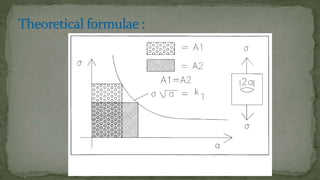
 The stress intensity factor K is used in fracture mechanics to
predict the stress state ("stress intensity") near the tip of a
crack caused by a remote load or applied stresses.
 Stress Intensity Factor is a quantity determined analytically and
varies as a function of the crack configuration and the external
loads are applied
 Critical stress intensity factor is independent of the crack
geometry and loading and may be regarded as a material
constant.
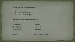
There are two main variables
 σ - Far Field Stress
 a - Crack length
Irwin defined the new variable, K
KI = σ(πa)1/2 Mode-I
KII = τ(πa)1/2 Mode-II
KIII = τ(πa)1/2 Mode-III
G=K2/E (For plane stress)
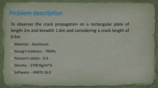
To observer the crack propagation on a rectangular plate of
length 2m and breadth 1.6m and considering a crack length of
0.6m
 Material: - Aluminum
 Young’s modulus: - 70GPa
 Poisson’s ration: - 0.3
 Density: - 2700 Kg/m^3
 Software: - ANSYS 16.0
 PRE PROCESSING:
 From main menu select Preferences select structural  ok
 From the main menu select Pre-processor
 Element type  Add/Edit/Delete  Add  select solid 
select 4 node 182  ok.
 Options  change K3 into the plane strain  ok  close.
 Material properties Material models Structural Linear
Elastic  Isotropic
 Define EX=70e9
 PRXY=0.33
 Density= 2700  ok  close
 From the main menu select Pre-processor  Modeling.
 Create the key point in the workspace
 Create  Key points  In active CS
X Y Z
0 0 0
1 0 0
1 0.8 0
0 0.8 0
0.3 0 0
 Click APPLY to all the points and for the last point click OK.
 Create LINES using the Key points
 Create  Lines  Straight Line  Select 1-5, 5-2, 2-3, 3-4 &
4-1
 From the main menu select MESHING
 Meshing  Size control  Manual sizing  Lines  Picked
lines select the lines 1, 2 & 5 Apply
 Assign the number of division equal to “4”
 Again select the lines 3 & 4
 Assign the number of division equal “6” and give space ratio as
“0.2”.
 Meshing  Sizing control  Manual size  Concentrate key
points
 Give radius R1=0.025
 No of element around the circumference = 16
 Change node position from no skewed 1/2pt → skewed 1/4pt
 Again go to modeling
 Modeling  Create  areas  Arbitrary  By lines 
select all five lines  ok
 Again go to meshing
 Meshing  mesh  areas  free  select the area  ok
 Defining loads
 Loads  define loads  apply  structural  displacement 
symmetric B.C.  with areas  select the line first and then area
 apply
 Define loads  apply  structural  force/moment  on nodes 
select the nodes on the top side  ok
 Define the direction of the force = “ fy”
 `And the value of forces = 750 N  ok
 SOULTION:
 Solve → current LS → ok
 POST PROCESSING:
 From utility menu → plot →nodes
 Defining path
 General postproc → path operation → define path → by
nodes → select the nodes → ok
 From utility menu → work plane → local coordinate system →
create local cs → by 3 nodes
 Selecting the three nodes as follows
 General postproc → option for output → change global CS to
local CS → local system reference no = 11 → ok
 RESULT:
 General post processing → nodal calculation → stress intensity
factor
 Click OK
 Hence the stress intensity factor (KI) = 922.00
 Hence the stress intensity factor of the given rectangular plate is (K) 922.00.
 Hence by using these software the crack propagation is measured.
Seshasai

More Related Content

PPTX
01_INTRODUCTION_TO_FRACTURE_MECHANICS_linkedin
PDF
Astm e399 12
PPTX
Damage tolerance analysis
PPTX
Damage tolerance and fracture mechanics
PDF
Chapter 8 mechanical failure
PDF
Fracture mechanics CTOD Crack Tip Opening Displacement
PPTX
Introduction to Fracture mechanics
PDF
30120140501010
01_INTRODUCTION_TO_FRACTURE_MECHANICS_linkedin
Astm e399 12
Damage tolerance analysis
Damage tolerance and fracture mechanics
Chapter 8 mechanical failure
Fracture mechanics CTOD Crack Tip Opening Displacement
Introduction to Fracture mechanics
30120140501010

What's hot (20)

DOCX
Fracture Mechanics & Failure Analysis:Lecture Toughness and fracture toughness
PPTX
Fracture mechanics
PDF
Elastic plastic fracture mechanics
PPT
Fracture Toughness I by Carl Ziegler
PDF
Fracture mechanics
PPTX
Mme 323 materials science week 11-12 - failure
PPTX
fracture mechanics presentation
PPTX
A fracture mechanics based method for prediction of
PPT
Determination Of Geometric Stress Intensity Factor For A Photoelastic Compac...
PDF
Mi 291 chapter 4 (learning from failure)
PPT
Structures and Materials- Section 7 Stress Concentration
PPT
Presentazione finale
PPTX
FRACTURE BEHAVIOUR OF NANOCOMPOSITES -FATIGUE
PPTX
Seminar on fatigue
PPT
Fracture toughness measurement testing
PPTX
Fracture mechanics
PDF
Determination of Stress Intensity Factor for a Crack Emanating From a Rivet ...
PPTX
FRACTURE BEHAVIOUR
PPSX
Failure Basics (strength of materials) - with animations if downloaded
PPTX
Failure mechanics: Fatigue Failure
Fracture Mechanics & Failure Analysis:Lecture Toughness and fracture toughness
Fracture mechanics
Elastic plastic fracture mechanics
Fracture Toughness I by Carl Ziegler
Fracture mechanics
Mme 323 materials science week 11-12 - failure
fracture mechanics presentation
A fracture mechanics based method for prediction of
Determination Of Geometric Stress Intensity Factor For A Photoelastic Compac...
Mi 291 chapter 4 (learning from failure)
Structures and Materials- Section 7 Stress Concentration
Presentazione finale
FRACTURE BEHAVIOUR OF NANOCOMPOSITES -FATIGUE
Seminar on fatigue
Fracture toughness measurement testing
Fracture mechanics
Determination of Stress Intensity Factor for a Crack Emanating From a Rivet ...
FRACTURE BEHAVIOUR
Failure Basics (strength of materials) - with animations if downloaded
Failure mechanics: Fatigue Failure
Ad

Viewers also liked (14)

PDF
Teori dasar electric
PDF
Bab 06 kriteria kegagalan lelah
PDF
Ib Nafems Samtech Blade Optimization & Advanced Fatigue Analysis
PPT
Cara Kerja Internet
PPT
Induktansi dan hukum faraday 1
PPTX
Induksi faraday FISIKA UNNES
PPT
FEA analysis of carbon fiber failure
PDF
Bab 05 kriteria kegagalan 1
PDF
Analisis Perpatahan Getas (Cleavage Fracture Of Analysis) Dengan Metode Studi...
PPT
Hukum faraday
DOCX
Laporan Kerja Proyek Akhir "Pemancar Wifi Wajan Bolic"
PPTX
Fatigue Analysis of Structures (Aerospace Application)
PPTX
Wireless Networking
PDF
Kelelahan Logam (Fatigue)
Teori dasar electric
Bab 06 kriteria kegagalan lelah
Ib Nafems Samtech Blade Optimization & Advanced Fatigue Analysis
Cara Kerja Internet
Induktansi dan hukum faraday 1
Induksi faraday FISIKA UNNES
FEA analysis of carbon fiber failure
Bab 05 kriteria kegagalan 1
Analisis Perpatahan Getas (Cleavage Fracture Of Analysis) Dengan Metode Studi...
Hukum faraday
Laporan Kerja Proyek Akhir "Pemancar Wifi Wajan Bolic"
Fatigue Analysis of Structures (Aerospace Application)
Wireless Networking
Kelelahan Logam (Fatigue)
Ad

Similar to Seshasai (20)

PPTX
mechanical failure.pptx
PPTX
mechanical failure.pptx
PPT
CHAPTER 1.ppt
PPT
CHAPTER 1.ppt introduction to design 20 marks
PPTX
analysis of aircraft & aerospace structures.pptx
PDF
Damage tolerance evaluation of wing in presence of large landing gear cutout ...
PDF
Damage tolerance evaluation of wing in presence of large landing gear cutout ...
PDF
MachineElement I_new nwefsdyvweyfkduvwe.pdf
PDF
Design of machine elements notes by Bhavesh Mhaskar
PPTX
FRACTURE MECHANICS FOR MECHANICAL ENGINEERING
PDF
Computational Fluid Dynamic Analysis and Structural Analysis of Ribbed Panel ...
PDF
Static Structural, Fatigue and Buckling Analysis of Jet Pipe Liner by Inducin...
PPTX
Effect of Overload on Fatigue Crack Growth Behavior of Air Frame Structure
PDF
experimental stress analysis-Chapter 7
PDF
11 Fracture Mechanics (3).pdf
PDF
IRJET- Stress Concentration of Plate with Rectangular Cutout
PDF
Evaluation of the mechanical properties through 3 points bending and tensile ...
PDF
DMM-AME012_ME_V SEM PPT corrected_compressed.pdf
PDF
Fracture mechanics based estimation of fatigue life of welds
PPTX
Design against fluctuating loads.pptx
mechanical failure.pptx
CHAPTER 1.ppt
CHAPTER 1.ppt introduction to design 20 marks
analysis of aircraft & aerospace structures.pptx
Damage tolerance evaluation of wing in presence of large landing gear cutout ...
MachineElement I_new nwefsdyvweyfkduvwe.pdf
Design of machine elements notes by Bhavesh Mhaskar
FRACTURE MECHANICS FOR MECHANICAL ENGINEERING
Computational Fluid Dynamic Analysis and Structural Analysis of Ribbed Panel ...
Static Structural, Fatigue and Buckling Analysis of Jet Pipe Liner by Inducin...
Effect of Overload on Fatigue Crack Growth Behavior of Air Frame Structure
experimental stress analysis-Chapter 7
11 Fracture Mechanics (3).pdf
IRJET- Stress Concentration of Plate with Rectangular Cutout
Evaluation of the mechanical properties through 3 points bending and tensile ...
DMM-AME012_ME_V SEM PPT corrected_compressed.pdf
Fracture mechanics based estimation of fatigue life of welds
Design against fluctuating loads.pptx

Recently uploaded (20)

PPTX
Geodesy 1.pptx...............................................
PDF
Mohammad Mahdi Farshadian CV - Prospective PhD Student 2026
PDF
The CXO Playbook 2025 – Future-Ready Strategies for C-Suite Leaders Cerebrai...
PPTX
Construction Project Organization Group 2.pptx
PPTX
IOT PPTs Week 10 Lecture Material.pptx of NPTEL Smart Cities contd
DOCX
573137875-Attendance-Management-System-original
PDF
BMEC211 - INTRODUCTION TO MECHATRONICS-1.pdf
PPTX
FINAL REVIEW FOR COPD DIANOSIS FOR PULMONARY DISEASE.pptx
PDF
Evaluating the Democratization of the Turkish Armed Forces from a Normative P...
PPTX
MCN 401 KTU-2019-PPE KITS-MODULE 2.pptx
PPT
Project quality management in manufacturing
PPTX
KTU 2019 -S7-MCN 401 MODULE 2-VINAY.pptx
PPTX
Sustainable Sites - Green Building Construction
PDF
composite construction of structures.pdf
PPTX
CARTOGRAPHY AND GEOINFORMATION VISUALIZATION chapter1 NPTE (2).pptx
PPTX
bas. eng. economics group 4 presentation 1.pptx
PDF
Operating System & Kernel Study Guide-1 - converted.pdf
PPTX
M Tech Sem 1 Civil Engineering Environmental Sciences.pptx
DOCX
ASol_English-Language-Literature-Set-1-27-02-2023-converted.docx
PPTX
web development for engineering and engineering
Geodesy 1.pptx...............................................
Mohammad Mahdi Farshadian CV - Prospective PhD Student 2026
The CXO Playbook 2025 – Future-Ready Strategies for C-Suite Leaders Cerebrai...
Construction Project Organization Group 2.pptx
IOT PPTs Week 10 Lecture Material.pptx of NPTEL Smart Cities contd
573137875-Attendance-Management-System-original
BMEC211 - INTRODUCTION TO MECHATRONICS-1.pdf
FINAL REVIEW FOR COPD DIANOSIS FOR PULMONARY DISEASE.pptx
Evaluating the Democratization of the Turkish Armed Forces from a Normative P...
MCN 401 KTU-2019-PPE KITS-MODULE 2.pptx
Project quality management in manufacturing
KTU 2019 -S7-MCN 401 MODULE 2-VINAY.pptx
Sustainable Sites - Green Building Construction
composite construction of structures.pdf
CARTOGRAPHY AND GEOINFORMATION VISUALIZATION chapter1 NPTE (2).pptx
bas. eng. economics group 4 presentation 1.pptx
Operating System & Kernel Study Guide-1 - converted.pdf
M Tech Sem 1 Civil Engineering Environmental Sciences.pptx
ASol_English-Language-Literature-Set-1-27-02-2023-converted.docx
web development for engineering and engineering

Seshasai

  • 2. Crack Propagation behavior is a significant problem in Industries. Aerospace Structures, Pressure Vessels, gas turbine engines and pipe lines in oil and gas industry are examples, Where Failure could lead to damages and loss of life as well. For example Crack found in turbine blade of Aircraft engine and Shutting down of pipe line of process industry leads to not only economical loss it affects other dependent industries. The presence of Crack does not mean structure or component is unsafe, it is necessary to know how long initial crack size take grow at critical size at which component or structure would become fail or unsafe. And also it is necessary to know how crack evolves and its rate of propagation, hence we should be able to estimate service life of a component .Cost involved if in service Component found crack, initiated for numerical methods to predict crack propagation. Not only in above said, crack propagation analysis is required studying effect of surface treatment etc. Until recently Crack Propagation behavior is predicted experimentally, which is time consuming, ever since development of high speed computers and commercially available fem coding, industries using soft ware’s to predict crack propagation. In this project obtained stress intensity factor from ANSYS. And Predicting crack growth prediction. Analysis is carried on component of AERO STRCTURE
  • 3.  Fracture means the cracking or breaking of a hard object or material. What is fracture? Breaking of Materials High sulphur in material Cold waters Welding instead of riveting Continuity of the structure Applied stress Microcracks
  • 4. Factors affecting fracture Thermal expansion Quality of surfacesMagnitude of stress
  • 5.  Brittle deformation: it occurs (in rocks) when a rock breaks or fractures due to stress. This happens in high pressure but low temperature environments  Elastic deformation: An object can bend or flex temporarily and will “ spring back" to its original shape, but at some point it will also fail.  Ductile deformation: Any strain is irreversible and the rock deforms readily (Think taffy puller). Often in a single fault all three forms of deformation take place in that order as depth increases. Brittle & Ductile Fracture
  • 6.  Fracture mechanics is the field of mechanics concerned with the study of the propagation of cracks in materials. It uses methods of analytical solid mechanics to calculate the driving force on a crack and those of experimental solid mechanics to characterize the material's resistance to fracture.  Fracture mechanics is based on the implicit assumption that there exists a crack in a work component.  It is the study of flaws and cracks in materials.  Mostly deals with crack growth.
  • 7. • Strength of Material approach does not anticipate the presence of a crack or does via concentration factors • Presence of cracks can significantly decrease the structural strength and reliability 𝜎 = 𝐹 𝐴 𝜎 ≫ 𝐹 𝐴
  • 8. • Flaw Size (a) is an important parameter in fracture mechanics approach • Fracture Toughness replaces strength of material 𝑲 𝑰𝑪 For Linear-Elastic Fracture Mechanics (LEFM), fracture toughness of a material is determined from “Stress Intensity Factor” For Elastic-Plastic Fracture Mechanics(EPFM), fracture toughness is determined via energy required to grow a crack 𝑱 𝑰𝑪 𝜎 ≫ 𝐹 𝐴 a
  • 9. • Probably encountered in any industry dealing with structures – Automotive – Electronics – Healthcare – Aviation – Civil – Nuclear – Defense – Maritime
  • 10. • Physically, cracks initiate from; – An imperfection – An already existing crack – A damaged (locally weakened) area • A failure analysis must include; – Stress analysis – Failure criterion
  • 11. • A. Griffith (1893-1963) published the results of his studies on brittle fracture • He found the strength of glass depended on the size of microscopic cracks
  • 13. Three Modes of Fracture :  Mode I denotes a symmetric opening (opening or tension mode)  Mode II denotes an antisymmetric separation (In-plane shear mode)  Mode III denotes an antisymmetric separation (out-of-plane shear or tearing mode)  Crack growth usually takes place in mode I or close to it.  The crack “adjusts” itself such that the load is perpendicular to the crack faces.
  • 14.  The stress intensity factor K is used in fracture mechanics to predict the stress state ("stress intensity") near the tip of a crack caused by a remote load or applied stresses.  Stress Intensity Factor is a quantity determined analytically and varies as a function of the crack configuration and the external loads are applied  Critical stress intensity factor is independent of the crack geometry and loading and may be regarded as a material constant.
  • 15. There are two main variables  σ - Far Field Stress  a - Crack length Irwin defined the new variable, K KI = σ(πa)1/2 Mode-I KII = τ(πa)1/2 Mode-II KIII = τ(πa)1/2 Mode-III G=K2/E (For plane stress)
  • 16. To observer the crack propagation on a rectangular plate of length 2m and breadth 1.6m and considering a crack length of 0.6m  Material: - Aluminum  Young’s modulus: - 70GPa  Poisson’s ration: - 0.3  Density: - 2700 Kg/m^3  Software: - ANSYS 16.0
  • 17.  PRE PROCESSING:  From main menu select Preferences select structural  ok
  • 18.  From the main menu select Pre-processor  Element type  Add/Edit/Delete  Add  select solid  select 4 node 182  ok.
  • 19.  Options  change K3 into the plane strain  ok  close.
  • 20.  Material properties Material models Structural Linear Elastic  Isotropic  Define EX=70e9  PRXY=0.33  Density= 2700  ok  close
  • 21.  From the main menu select Pre-processor  Modeling.  Create the key point in the workspace  Create  Key points  In active CS X Y Z 0 0 0 1 0 0 1 0.8 0 0 0.8 0 0.3 0 0
  • 22.  Click APPLY to all the points and for the last point click OK.  Create LINES using the Key points  Create  Lines  Straight Line  Select 1-5, 5-2, 2-3, 3-4 & 4-1
  • 23.  From the main menu select MESHING  Meshing  Size control  Manual sizing  Lines  Picked lines select the lines 1, 2 & 5 Apply  Assign the number of division equal to “4”  Again select the lines 3 & 4  Assign the number of division equal “6” and give space ratio as “0.2”.
  • 24.  Meshing  Sizing control  Manual size  Concentrate key points  Give radius R1=0.025  No of element around the circumference = 16  Change node position from no skewed 1/2pt → skewed 1/4pt
  • 25.  Again go to modeling  Modeling  Create  areas  Arbitrary  By lines  select all five lines  ok
  • 26.  Again go to meshing  Meshing  mesh  areas  free  select the area  ok
  • 27.  Defining loads  Loads  define loads  apply  structural  displacement  symmetric B.C.  with areas  select the line first and then area  apply  Define loads  apply  structural  force/moment  on nodes  select the nodes on the top side  ok  Define the direction of the force = “ fy”  `And the value of forces = 750 N  ok
  • 28.  SOULTION:  Solve → current LS → ok
  • 29.  POST PROCESSING:  From utility menu → plot →nodes
  • 30.  Defining path  General postproc → path operation → define path → by nodes → select the nodes → ok
  • 31.  From utility menu → work plane → local coordinate system → create local cs → by 3 nodes
  • 32.  Selecting the three nodes as follows
  • 33.  General postproc → option for output → change global CS to local CS → local system reference no = 11 → ok
  • 34.  RESULT:  General post processing → nodal calculation → stress intensity factor
  • 35.  Click OK  Hence the stress intensity factor (KI) = 922.00
  • 36.  Hence the stress intensity factor of the given rectangular plate is (K) 922.00.  Hence by using these software the crack propagation is measured.