


Simple stress
- 1. Chapter : 01 Simple Stresses Normal Stresses Shear Stress Bearing Stress Thin-walled Pressure Vessels Prof. Dr. Md. Shawkut Ali Khan Faculty Department of Mechanical Engineering IUBAT
- 2. Simple Stress Stress is defined as the strength of a material per unit area i.e resisting force per unit area. T he stress develop due to the load which act on the perpendicular of the surface of the material is called normal stress. Formally it is expressed in psi, N/mm2 or Mpa. And mathematically we can express Where, P = applied normal load in Newton. A= Area in mm. Normal stress is either tensile stress or compressive stress. Members subject to tensile force are under tensile stress, while members subject to compressive force are under compressive stress. Compressive force will tend to shorten the member. Tension force on the other hand will tend to lengthen the member.
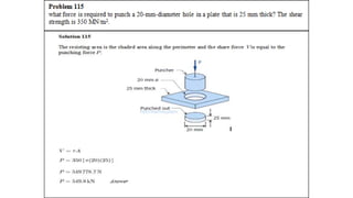
- 3. A F A P ave Single Shear Shear Stress Forces parallel to the area resisting the force cause shearing stress. Usually shearing force act parallel to the surface. Shearing force is also known as tangential stress and mathematically Where, V = the resultant shearing force A= Area of the surface. Here the force act on the nut due to the applied force P, is called Shear force.
- 4. Bearing Stress Bearing stress is the contact pressure between the separate bodies. It differs from compressive stress, as it is an internal stress caused by compressive forces. Mathematically, where, Pb = Applied load Ab = Area of the hole = td Here due to pressure , there will be developed a stress between the plate & Nut, which is ultimately effect the hole of the plate, the stress develop on the hole is called bearing stress. Pb
- 5. A composite bar consists of an aluminum section rigidly fastened between a bronze section and a steel section as shown in figure 1-8a. Axial loads are applied at the positions indicated. Determine the stress in each section. Solution 101: For Aluminum: For Steel: (Answer) (Answer) Problem101 For Bronze: (Answer) Bronze Aluminum Steel Figure 1-8 (a) Figure 1-8 (b)
- 6. For the truss shown in figure 1-9a, determine the stress in members AC and BD.The cross-sectional area of each member is 900 Solution 102: Problem10 2 The three assumptions used in the elementary analysis of trusses are as follows: 1. Weights of the members are neglected. 2. All connections are smooth pins. 3. All external loads are applied directly to the pin. Analyzing the free-body diagram in figure 1-9b, we have The minus sign indicates that the 66.7kN force in member AB is compressive. The force in member AC is 53.4 kN, tension. 1 Figure 1-9 (a) (b) Figure 1-9 For Joint A
- 7. The free-body diagram of the portion of the truss to the left of section (2) is shown in figure 1-9c. To calculate the force BD, The stresses in member AC and BD are, (Answer) (Answer) (c) Figure 1-9 For Joint B
- 8. Problem103 The block of weight in figure hangs from the pin at A. The bas AB and AC are pined to the support at B and C. The areas are 800 for AB and 400 for AC. Neglecting the weight of the bars. Determine the maximum safe value of W if the stress in AB is limited to 110 MPa and that in AC to 120 Mpa. Solution 103 Solving simultaneously, we have and Figure 1-10 (a) W Figure 1-10 (b)
- 9. For AB: For AC: Safe value of W is 61.7 kN (Answer)
- 10. Simple Stress Problem 104 A hollow steel tube with an inside diameter of 100 mm must carry a tensile load of 400 kN. Determine the outside diameter of the tube if the stress is limited to 120 MN/m2. – See SoL: where, Thus answer
- 11. Simple Stress Prob.105. A homogeneous 800 kg bar AB is supported at either end by a cable as shown in Fig. P- 105. Calculate the smallest area of each cable if the stress is not to exceed 90 MPa in bronze and 120 MPa in steel. Solution 105 For bronze cable: answer For steel cable: answer
- 12. Simple Stress Problem 106 The homogeneous bar shown in Fig. P-106 is supported by a smooth pin at C and a cable that runs from A to B around the smooth peg at D. Find the stress in the cable if its diameter is 0.6 inch and the bar weighs 6000 lb. Solution 106 answer
- 13. A rod is composed of an aluminum section rigidly attached between steel and bronze sections, as shown in Fig. P-107. Axial loads are applied at the positions indicated. If P = 3000 lb and the cross sectional area of the rod is 0.5 in2, determine the stress in each section. Solution 107: For aluminum: For Bronze: (Answer) (Answer) Problem107
- 14. An aluminum rod is rigidly attached between a steel rod and a bronze rod as shown in Fig. P-108. Axial loads are applied at the positions indicated. Find the maximum value of P that will not exceed a stress in steel of 140 MPa, in aluminum of 90 MPa, or in bronze of 100 MPa. Solution108: For bronze: For aluminum: For Steel: For safe value of P, use the smallest above. Thus, Problem 108 (Answer)
- 15. Simple Stress Problem 109 Determine the largest weight W that can be supported by two wires shown in Fig. P-109. The stress in either wire is not to exceed 30 ksi. The cross-sectional areas of wires AB and AC are 0.4 in2 and 0.5 in2, respectively. Solution 109 Free body diagram of Joint A For wire AB: By sine law (from the force polygon): For wire AC: For safe load W, answer
- 16. Problem 110 A 12-inches square steel bearing plate lies between an 8-inches diameter wooden post and a concrete footing as shown in Fig. P-110. Determine the maximum value of the load P if the stress in wood is limited to 1800 psi and that in concrete to 650 psi. Solution 110: For wood For concrete: Simple Stress From FBD of Concrete: For safe load P, answer From FBD of Wood:
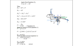
- 17. Simple Stress Problem 111 For the truss shown in Fig. P-111, calculate the stresses in members CE, DE, and DF. The cross- sectional area of each member is 1.8 in2. Indicate tension (T) or compression (C). Solution 111 At joint F: At joint D: By symmetry: At joint E: Stresses: (Stress = Force/Area) answer answer answer
- 18. Problem 112 Determine the cross-sectional areas of members AG, BC, and CE for the truss shown in Fig. P- 112. The stresses are not to exceed 20 ksi in tension and 14 ksi in compression. A reduced stress in compression is specified to reduce the danger of buckling.
- 52. A tank or pipe carrying a fluid or gas under a pressure is subjected to tensile forces, which resist bursting, developed across longitudinal and transverse sections.
- 53. The forces acting are the total pressures caused by the internal pressure p and the total tension in the walls T. If there exist an external pressure po and an internal pressure pi, the formula may be expressed as: TANGENTIAL STRESS, σt (Circumferential Stress) Consider the tank shown being subjected to an internal pressure p. The length of the tank is L and the wall thickness is t. Isolating the right half of the tank:
- 54. LONGITUDINAL STRESS, σL Consider the free body diagram in the transverse section of the tank: The total force acting at the rear of the tank F must equal to the total longitudinal stress on the wall PT = σLAwall. Since t is so small compared to D, the area of the wall is close to πDt If there exist an external pressure po and an internal pressure pi, the formula may be expressed as: It can be observed that the tangential stress is twice that of the longitudinal stress.
- 55. SPHERICAL SHELL: If a spherical tank of diameter D and thickness t contains gas under a pressure of p = pi - po, the stress at the wall can be expressed as:
- 58. TANGENTIAL STRESS, σt (Circumferential Stress) LONGITUDINAL STRESS, σL
- 59. A cylindrical steel pressure vessel 400 mm in diameter with a wall thickness of 20 mm, is subjected to an internal pressure of 4.5 MN/m2. (a) Calculate the tangential and longitudinal stresses in the steel. (b) To what value may the internal pressure be increased if the stress in the steel is limited to 120 MN/m2? (c) If the internal pressure were increased until the vessel burst, sketch the type of fracture that would occur. Problem133 Solution 133 Part (a) Tangential stress (longitudinal section): (answer) Longitudinal Stress (transverse section): (answer)
- 60. Part (b): From (a), and thus, this shows that tangential stress is the critical. (Answer) The bursting force will cause a stress on the longitudinal section that is twice to that of the transverse section. Thus, fracture is expected as shown.
- 61. Problem 134 The wall thickness of a 4-ft-diameter spherical tank is 5/6 inch. Calculate the allowable internal pressure if the stress is limited to 8000 psi. Solution 134 Total internal pressure: Resisting wall: (Answer)
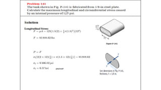
- 62. Calculate the minimum wall thickness for a cylindrical vessel that is to carry a gas at a pressure of 1400 psi. The diameter of the vessel is 2 ft, and the stress is limited to 12 ksi. Solution 135 The critical stress is the tangential stress (Answer) Problem 135
- 63. A cylindrical pressure vessel is fabricated from steel plating that has a thickness of 20 mm. The diameter of the pressure vessel is 450 mm and its length is 2.0 m. Determine the maximum internal pressure that can be applied if the longitudinal stress is limited to 140 MPa, and the circumferential stress is limited to 60 MPa. Solution 136 Based on circumferential stress (tangential): Based on longitudinal stress: Use (Answer) Problem 136
- 64. A water tank, 22 ft in diameter, is made from steel plates that are 1/2 in. thick. Find the maximum height to which the tank may be filled if the circumferential stress is limited to 6000 psi. The specific weight of water is 62.4 lb/ft3. Problem 137 Solution 137 Assuming pressure distribution to be uniform: (Answer)
- 65. Based on actual pressure distribution: = volume of pressure diagram Total hydrostatic force, F: