


![Sequence Diagram - Case Study 2
23
Basic Course of Action:
1. The use case begins when a customer indicates he/she wants to book a car from UI 1 - Home page screen.
2. The customer selects the booking option.
3. The system navigates the customer to UI 2 - Booking Screen.
4. The customer inputs his/her booking details to search for a suitable car via UI 2 - Booking Screen.
5. The system searches for matched cars. [Alternate Course A]
6. The system displays UI 3 Available Cars Screen, which indicates the list of available car types.
7. The customer views and then selects the car type that he/she is interested in. [Alternate Course B].
8. The system validates if the customer age is 18 years old or older and has a driving license. [Alternate Course C]
9. The system displays the price of the car for the person via UI 4 Display Car Price Screen.
10. The customer confirms he/she wants to book the car via UI 4 Display Car Price Screen. [Alternate Course D]
11. The system navigates the customer to UI 5 Customer Personal Details.
12. The customer inputs his personal details.
13. The system stores the customer’s details and the reservation details.
14. The system displays UI 6 Payment Screen.
15. The customer inputs his/her credit card details.
16. The system verifies the customer credit card via external system.
17. The system bills the customer for his/her booking. [Error]
18. The system informs the customer that he/she booked the car via UI 7 Thank You Screen.
19. The use case ends.](https://image.slidesharecdn.com/csit114-week7systemmodellingv1-241102204605-a2fc61c1/85/System-Modelling-in-Software-Engineering-23-320.jpg)


![Sequence Diagram - Class Activity
E-Scooter Rental Application
Main Success Scenario:
1. The customer clicks on the E-Scooter rental icon of the application on their mobile device via
UI 1 - Mobile Application Icon.
2. The E-Scooter application navigates the user to UI 2 - login screen.
3. The customer logs in using their credentials (username and password).
4. The E-Scooter application verifies the credentials. [Error – Invalid credentials]
5. The E-Scooter application displays a map with the locations of available E-Scooters in Dubai via
UI 3 - E-scooter Map.
6. The customer selects an available E-Scooter on the map to view more details, such as the
scooter's current battery status and estimated distance to their location.
7. The E-Scooter Application displays more details about the scooter on UI 4 E-Scooter details
Screen.
34](https://image.slidesharecdn.com/csit114-week7systemmodellingv1-241102204605-a2fc61c1/85/System-Modelling-in-Software-Engineering-34-320.jpg)
![Sequence Diagram - Class Activity
E-Scooter Rental Application – Case study
Main Success Scenario:
8. The customer decides to rent the selected E-Scooter and taps the "Rent“
button.
9. The application prompts the customer to confirm the rental, and displays information
about the cost per hour, the E-Scooter battery status, and location via UI 5 –
Confirmation Rent.
10. The customer confirms the rental via UI 5 – Confirmation Rent. [ Alternate Course A
– The Customer Declined the rent]
11. The E-Scooter application processes and updates the rental request, reserves the
selected E-Scooter for the customer, and sends a confirmation to the customer along
with a digital unlock code or QR code on UI 6 – unlock code.
12. The customer arrives at the location of the E-Scooter, they enter the unlock code or
scan the QR code on the E-Scooter using the E-scooter unluck device via UI 7 – Lock and
unlock device screen.
35](https://image.slidesharecdn.com/csit114-week7systemmodellingv1-241102204605-a2fc61c1/85/System-Modelling-in-Software-Engineering-35-320.jpg)


System Modelling in Software Engineering
- 1. University of Wollongong in Dubai
- 2. CSIT114 – System Analysis System Modeling Dr. Haitham Yaish Dr. Zeenath Reza Khan
- 3. Document Change Control Version Author Date Change Description 1.0 Dr. Haitham Yaish Autumn 2023 Defined the first version 3
- 4. • Graphical description of use cases • UML Sequence Diagram • How to create Sequence Diagram ? • Sequence Diagram – Examples • Sequence Diagram – Case Studies • Sequence Diagram – Class Activity • Analysis vs. Design Agenda 4
- 5. • The textual description is essential for the documentation of use cases, as it alone enables ease of communication with users, as well as agreeing on domain terminology that is used. • However, the text also has its disadvantages as it difficult to show how the sequences follow one another. • It is therefore recommended to complete the textual description with one or more dynamic UML diagrams. Graphical description of use cases
- 6. Graphical description of use cases
- 7. • Activity diagrams are used when you want to model the workflow or business processes associated with a use case. • For certain scenarios, the sequence diagram works well. • Sequence diagrams are primarily used to model interactions between objects or components. If your focus is on how different objects or components collaborate to complete a use case. • Also, we taught you in this subject how to present Use cases scenario using Robustness Analysis (Robustness Diagram) Graphical description of use cases
- 8. Model The Behaviour of Use Cases Using UML Sequence Diagram UML Sequence Diagram Notation Description Participant Represent an object or an actor or the system. Message Defines a particular communication between Lifelines of an Interaction between participants. Lifeline Represents an individual participant in the Interaction as vertical progression. Combined Fragment Represented as a box, which encloses a portion of the interactions within a sequence diagram and is described as control flow.
- 9. Participant • A participant is either an actor, an object, or the system. • A lifeline represent the Interactions of a participant • Activation a thin rectangle on a lifeline represents the period during which an element is performing an operation. 9 UML Sequence Diagram
- 10. Messages 10 UML Sequence Diagram Synchronous Messages It must wait until the message is done. Asynchronous Message It can continue processing and doesn't have to wait for a response. Return Message Dotted line and an open arrowhead Pointing back to the original lifeline
- 11. Messages 11 UML Sequence Diagram Create Message A message that creates a participant Destroy Message A message that destroys a participant Self Message A message an object sends to itself, or an activity the same object does.
- 12. • This sequence diagram just showing how to depict messages on a sequence diagram (regardless of the sequence). https://www.conceptdraw.com/examples/sequence-diagram-how-to-draw-asynchronous 12 UML Sequence Diagram
- 13. Fragments 13 UML Sequence Diagram Alternate Option Loop Parallel Reference
- 14. • It is recommend that you present the sequence diagram by showing the primary actor on the left, then an object representing the system in a black box on the right • If your use case that you want to present has Primary and Secondary actors, present the secondary actors that may be requested during the scenario on the right of the system participant . UML Sequence Diagram
- 15. How to create Sequence Diagram ? • Identify participants that interact in a use-case scenario - SSD: actors and the system - DSD: actors and objects • Set the lifeline for each participant • Add messages by drawing arrows - Show how they are passed from an object to another . - Include any parameters in round brackets - () . - Obvious return values are excluded. • Add execution occurrence (activation zone) to each object’s lifeline • Validate the sequence diagram - Ensure that it depicts all the steps in the textual description of a use case . - What are the main tasks performed by each actor?
- 16. • The *address details suggests that the specific value of "address details" returned by the enterAddress interaction is not crucial to the sequence diagram, and it can be any valid value. Sequence Diagram – Example 1
- 17. • Process Sale Scenario (with some explanations) Sequence Diagram – Example 2
- 18. • Process Sale Scenario (without explanation notes) Sequence Diagram – Example 2
- 19. Sequence Diagram – Example 3
- 20. Sequence Diagram - Case Study 1 20 Use the Enrol in Seminar System Use Case to draw a System Sequence Diagram (SSD)
- 21. Sequence Diagram - Case Study 1 21 Use the Enrol in Seminar System Use Case to draw a System Sequence Diagram (SSD)
- 22. Sequence Diagram - Case Study 2 22 Car Rental Booking Use Case Name: Car Rental Booking. Identifier: UC 1 Description: This use case describes the events of a customer who wants to make online booking to rent a car. Preconditions: The customer who would like to book a car for rental must be over 18 years old or older and has a driving license. Postconditions: None.
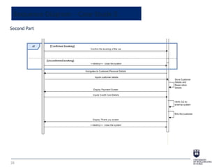
- 23. Sequence Diagram - Case Study 2 23 Basic Course of Action: 1. The use case begins when a customer indicates he/she wants to book a car from UI 1 - Home page screen. 2. The customer selects the booking option. 3. The system navigates the customer to UI 2 - Booking Screen. 4. The customer inputs his/her booking details to search for a suitable car via UI 2 - Booking Screen. 5. The system searches for matched cars. [Alternate Course A] 6. The system displays UI 3 Available Cars Screen, which indicates the list of available car types. 7. The customer views and then selects the car type that he/she is interested in. [Alternate Course B]. 8. The system validates if the customer age is 18 years old or older and has a driving license. [Alternate Course C] 9. The system displays the price of the car for the person via UI 4 Display Car Price Screen. 10. The customer confirms he/she wants to book the car via UI 4 Display Car Price Screen. [Alternate Course D] 11. The system navigates the customer to UI 5 Customer Personal Details. 12. The customer inputs his personal details. 13. The system stores the customer’s details and the reservation details. 14. The system displays UI 6 Payment Screen. 15. The customer inputs his/her credit card details. 16. The system verifies the customer credit card via external system. 17. The system bills the customer for his/her booking. [Error] 18. The system informs the customer that he/she booked the car via UI 7 Thank You Screen. 19. The use case ends.
- 24. Sequence Diagram - Case Study 2 24 Alternate Course A: The required car type is not available. A5. The system determines that the car type is not available. A6. The system informs the customer that the required car is not available via UI 8 Not Available Car Screen. A7. The use case ends. Alternate Course B: The customer decides not to book a car. B7. The customer views the available cars and he/she is not interested in any of the cars. B8. The use case ends. Alternate Course C: The customer is not eligible to book a car. C8. The system determines the customer is not eligible to book a car. C9. The system informs the customer he/she is younger than 18 years old or doesn’t have driver license via UI 9 Not Eligible Screen. C10. The use case ends. Alternate Course D: The customer decides not to proceed with the booking. D10. The customer views the price of the car and he/she decides not to book the car. D11. The use case ends. Error: The customer credit card details are not valid. E17. The system determines the customer’s credit card is not valid. E18. The system displays error message to the customer via UI 10 Not valid Credit Card Screen. E19. The use case ends.
- 25. Sequence Diagram - Case Study 2 25 Car Rental Booking Database
- 26. Sequence Diagram - Case Study 2 26
- 27. Sequence Diagram - Case Study 2 27 First Part
- 28. Sequence Diagram - Case Study 2 28 Second Part
- 29. Sequence Diagram - Case Study 2 29 Version 2 - One of the steps of creating SSD is to Validate the sequence diagram . Here we added in this version the Error scenario.
- 30. Sequence Diagram - Case Study 2 30 Version 2 - One of the steps of creating SSD is to Validate the sequence diagram . Here we added in this version the Error scenario. (First Part)
- 31. Sequence Diagram - Case Study 2 31 Version 2 - One of the steps of creating SSD is to Validate the sequence diagram . Here we added in this version the Error scenario. (Second Part)
- 32. Sequence Diagram - Class Activity E-Scooter Rental Application Use Case Description: E-Scooter Rental Application Use Case Title: Renting an E-Scooter Primary Actor: Customer Preconditions: 1. The customer has a valid user account with the E- Scooter rental service with money account balance. 2. The customer has the E-Scooter rental application installed on their mobile device. 32
- 33. Sequence Diagram - Class Activity E-Scooter Rental Application Postconditions: 1. The E-Scooter is locked and parked securely. 2. The E-Scooter rental application updates the availability of the E-Scooter for other potential renters. 3. The E-Scooter is available for the next customer to rent. 33
- 34. Sequence Diagram - Class Activity E-Scooter Rental Application Main Success Scenario: 1. The customer clicks on the E-Scooter rental icon of the application on their mobile device via UI 1 - Mobile Application Icon. 2. The E-Scooter application navigates the user to UI 2 - login screen. 3. The customer logs in using their credentials (username and password). 4. The E-Scooter application verifies the credentials. [Error – Invalid credentials] 5. The E-Scooter application displays a map with the locations of available E-Scooters in Dubai via UI 3 - E-scooter Map. 6. The customer selects an available E-Scooter on the map to view more details, such as the scooter's current battery status and estimated distance to their location. 7. The E-Scooter Application displays more details about the scooter on UI 4 E-Scooter details Screen. 34
- 35. Sequence Diagram - Class Activity E-Scooter Rental Application – Case study Main Success Scenario: 8. The customer decides to rent the selected E-Scooter and taps the "Rent“ button. 9. The application prompts the customer to confirm the rental, and displays information about the cost per hour, the E-Scooter battery status, and location via UI 5 – Confirmation Rent. 10. The customer confirms the rental via UI 5 – Confirmation Rent. [ Alternate Course A – The Customer Declined the rent] 11. The E-Scooter application processes and updates the rental request, reserves the selected E-Scooter for the customer, and sends a confirmation to the customer along with a digital unlock code or QR code on UI 6 – unlock code. 12. The customer arrives at the location of the E-Scooter, they enter the unlock code or scan the QR code on the E-Scooter using the E-scooter unluck device via UI 7 – Lock and unlock device screen. 35
- 36. Sequence Diagram - Class Activity E-Scooter Rental Application Main Success Scenario: 13. The rental information will be updated in the application. 14. The E-Scooter is unlocked, and the customer is now able to use it. 15. The customer rides the E-Scooter to their desired location. 16. Once the customer has completed their ride, they park the E-Scooter in a designated parking area and securely lock it using UI 7 – Lock and unlock device screen. 17. The E-Scooter application registers the end of the ride and deducts the ride from the customer’s money account balance. 18. The application will send a message to the customer to display the rental summary, including the total cost and distance travelled and the details will be displayed on UI 8 – Rental summary screen. 36
- 37. Sequence Diagram - Class Activity E-Scooter Rental Application Alternative Paths: Alternate Course A: The Customer Declined the rent A10. The customer views the E-Scooter details and he/she decided not to proceed with renting it. A11. The use case ends. Error: The credentials of the customer are invalid E4. The E-Scooter system verifies and determines the customer’s credentials are invalid. E5. The E-Scooter system displays error message to the customer via UI 9 Invalid credentials screen. E6. The use case ends. 37
- 38. Sequence Diagram - Class Activity E-Scooter Rental Application 38 Data Storage (Database)
- 39. Sequence Diagram - Class Activity E-Scooter Rental Application 39 Work in a groups to analyse the E-Scooter Rental Application use case description and the data storage to construct E-Scooter Rental Application System Sequence Diagram (SSD).
- 41. Analysis and design models Analysis vs. Design
- 42. SSD Vs. DSD The difference between System Sequence Diagram and Design Sequence Diagram SSD Analysis Phase Participants are actors and the system DSD Design Phase Participants are actors and objects defining the system structure
- 43. System Design Core process 4: Design activities Activity 1: Describe the environment Activity 2: Design the application components Activity 3: Design user interface Activity 4: Design the databases Activity 5: Design the software classes and methods We will cover this part next lecture in more details 43
- 44. References • Satzinger, J., Jackson, R. & Burd, S. (2016) Systems Analysis And Design In A Changing World. 7th Edition, Boston, Mass. Cengage Learning. • Petre, M., 2013, May. UML in practice. In 2013 35th international conference on software engineering (icse) (pp. 722-731). IEEE. • What is Sequence Diagram? https://www.visual-paradigm.com/guide/uml-unified-modeling-language/what-is-s equence-diagram/ . Last Accessed 25 October 2023 • Sequence Diagram. https://www.smartdraw.com/sequence-diagram/ . Last Accessed 25 October 2023 • System Sequence Diagram: A Complete Tutorial . https://www.edrawsoft.com/article/uml-system-sequence-diagram.html .Last Accessed 25 October 2023 44
- 45. THANK YOU Any Question ? 45
Editor's Notes
- #10: If a caller sends a synchronous message, it must wait until the message is done, such as invoking a subroutine. If a caller sends an asynchronous message, it can continue processing and doesn't have to wait for a response.
- #11: If a caller sends a synchronous message, it must wait until the message is done, such as invoking a subroutine. If a caller sends an asynchronous message, it can continue processing and doesn't have to wait for a response.
- #19: getNextSale, setShipper, recordShippedItem, initiateBackorder, and getShippingLabel. No parameter is needed for getNextSale because the system will automatically return the information for the next sale to be shipped. The shipper is selected by the actor—probably from a list on the form or page—so the parameter is shipperID. There is a loop frame that repeats for each sale item in the sale. Inside the loop frame is an alt frame that tests the whether each sale item is available to ship. If the item can be shipped, the recordShippedItem message is sent to the system. If the item cannot be shipped because it is out of stock or perhaps damaged, the initiateBackorder message is sent to the system. Finally, the getShippingLabel message requires two parameters: the size of the package and the weight. The system uses that information, along with the shipper and address, to produce the shipping label and record the cost. These first sections of this chapter have explained the models that are used in object-oriented development to specify the processing aspects of the new system. The use case descriptions, as provided by written narratives or activity diagrams, give the details of the internal steps within each use case. Precondition and postcondition statements help define the context for the use case—that is, what must exist before and after processing. Finally, the SSD describes the inputs and outputs that occur within a use case. Together, these models provide a comprehensive description of the system-processing requirements and give the foundation for systems design.