SlideShare a Scribd company logo
UPLOADED BY:
DAFER SIEF
PROPOSED DESIGN FOR :
UNIARC RESIDENCES ;
STUDENTS’ RESIDENCE IN INFRASTRUCTURE UNIVERSITY KUALA LUMPUR (IUKL)
A building primarily to provide sleeping and residential quarters for students and staffs in this university.
uni arc
ABOUT THE SITE:
Infrastructure University Kuala-
Lumpur (IUKL)
Address: Unipark Suria, Jalan
Ikram-Uniten, 43000 Kajang,
Selangor Darul Ehsan, Malaysia.
GPS Coordinate : 2º58’ 46” N,
101º44/ 24”E
Project site : 19494.36 m²
PROPOSED SITE LOCATION
MASTER PLAN OF IUKL : SITE ANALYSIS :
WIND DIRECTION & SUN ORIENTATIONOVERVIEW :
Infrastructure University Kuala Lumpur
(IUKL) is a 100 acre campus. The campus is
accessible via North-south highway and is a
30 minutes drive from Kuala Lumpur city
center.
As the numbers of students and staffs of this
university is keep increasing, they need a
well designed of high-rise residence building
for accommodation and facility purposes.
sociability through the arc …
CONCEPT: Sociability Through The Arc.
Social interaction is a vital aspect of students life. Lacking in
causes social problems, apparently in Malaysia where ethnicity is
diverse. Each mind is unique in their own way., has the possibility to
gain significant achievements.
Although unorthodox in form, but we believe that such an approach
on bring about the purpose of the student life.
Sociability through the Arc is a solution to this problem where form
determines the student through a sense of community, not just in
education and the consistent pouring of books. A university is a
center of learning, networking, participation and recreation, thus, a
student residence should act the same.
Though form follows function, circular shapes can often create
different results. Circularity provides a sense of unity and equality;
users would feel a communal spirit within them.
uni arc
uni arc
Sustainable material:
Instead of using traditional building
materials, the containers provide a
cheaper, safer and sustainable option
as a suitable building material.
Steel structure:
To engage in the extensive use of
steel, with minimum use of other
building materials such as concrete,
but also taking budget into account.
SCHEDULE OF ACCOMODATION (SOA)
1. General spaces ;
SCHEDULE OF ACCOMODATION (SOA)
2. Residences Spaces ;
SCHEDULE OF ACCOMODATION (SOA)
1. Facilities ;
Site Plan
Site Plan
uni arc
uni arc
uni arc
uni arc
uni arc
uni arc
uni arc
uni arc
Shipping containers are used to become the rooms of this buildings because it is cost effective and
fast method for construction.
Aspects Of The Building Design
The diagram shows the floor plan of rooms available for all three
blocks. Space planning becomes easy due to the fixed floor space.
Aspects Of The Building Design
1. 16 levels, 3blocks with a total of 330 rooms for each.
in one block of the residences, therefore the 3 blocks of UniArc Residences contains 990
of rooms including single, double and quad rooms. The buildings use different container
sizes to address the need for different size of rooms. The aesthetics of the containers
are exposed and cantilevered for a new style of exterior outlook of this residences.
Aspects Of The Building Design
2. Containers are used to become
the rooms
a) Single Room b) Double Room
Aspects Of The Building Design
c) Quadruple Room
Aspects Of The Building Design
b) Discussion Room
Aspects Of The Building Design
b) Study Room
3. Containers bolted together
Aspects Of The Building Design
The containers are simply bolted together and once installed at the site, windows are
fitted, the modules are decorated and furnished, and then the exterior of the building is
cladded.
Courtyard
Top Roof
Night Time
3. The construction did not require specialized labor and was 40 to 60% faster than the normal
reinforced concrete building in our country. This kind of building construction is estimated can
save at least 10% to 20% in cost.
Aspects Of The Building Design
4. Cost & Time Effect
CARGOTECTURE :
Shipping container architecture
is a form of architecture using steel intermodal containers as structural element.
It is also referred as cargotecture, a portmanteau of cargo with architecture.
Uses In Architecture ;
• As a building material
has grown in popularity of the past several years due to their inherent
strength, wide availability, and relatively low expense.
• Build homes with containers
because they are seen as more eco-friendly than traditional building
materials such as brick and cement.
Advantages :
1.Strength and durability.
2. Modular.
3. Labor.
4. Transport.
5. Availability.
6. Expense.
7. Foundations.
8. Eco-Friendly.
CARGOTECTURE :
BUILDING STRUCTURAL ANALYSIS
(STAAD.PRO DESIGN)
The concept of UniArc Residences which uses
shipping container as rooms and have 15 level
which occupied with 990 rooms and IBS system
more preferable and stable to support the
container load and live load around the building
transfer to beam and column n then transfer to
foundation. Steel materials are used as a column
and beam to support the container. The connection
between container and other structures which is
use welded and bolted connection between column
and beam. The design of this hostel was design in
STAAD.Pro V8i. Reinforced concrete slab was
assign for the walkway in the middle of the
building. The concept IBS system is used to
speedup construction period and flexible due to
container moveable load.
Figure 1: The shipping container, sized 12m x 3m is used.
BUILDING STRUCTURAL ANALYSIS
(STAAD.PRO DESIGN)
The shipping container’s weight was 2860 kg and pay load capacity is 25 000 kg and we can’t assign the container
in STAAD.Pro but we can assign the load of container on the member.
2860kg >> 28.47Kn
28.4Kn / area of container (12m x 3m) = 0.79Kn/m2
0.79Kn/m2 x horizontal length of beam + other load have to consider = …3.37.kN/m (depends on the length)
Dead Load = 3.37 kN/m
Dead Load =2.5kN/m (Hostel) refer to BS Code
Life Load = 2.7kN/m
uni arc
Sl.No. Description UDL Load (kN/m2) Concentrated Load (kN)
1. Bathrooms and toilets in all types of
buildings
2 1.8
2. Living and bed rooms
3 Office rooms in
(i) Hostel, hotels, hospitals and
business building with
separate store
2.5
(Live Load)
2.7
(ii) In assembly buildings 3 4.5
4. Kitchens in
(i) Dwelling houses 2 1.8
(ii) Hostels, hotels and
hospitals
3 4.5
5. Banking halls, class rooms, X-ray rooms,
operation rooms
3 4.5
6. Dining rooms in
(i) Educational buildings,
institutional and mercantile
buildings
3 2.7
(ii) Hostels and hotels 4 2.7
7. Corridors, passages, stair cases in
(i) Dwelling houses, hotels,
and hostels
3 4.5
(ii) Educational, institutional
and assembly buildings
4 4.5
(iii) Mercantile buildings 5 4.5
8. Reading rooms in libraries
(i) With separate storage 3 4.5
(ii) Without separate storage 4 4.5
Column Stump : UC356 X 368 X
177
Column Size for building : UC356 X 368 X 153
Beam Size : UB305 X 165 X 54
Container Holder size : TUB1608012.5
Walkway : Reinforced concrete slab size
0.2 m was merged with UB305 X
165 X 54
• Bolt Connection which is use M30 to connect column and
beam and M20 for container holder and container itself
• Shear wall use for lift core
Property of Steel Materials
STAADPRO DESIGN
Figure 2: Whole structure and the member of column and beam Figure 3: Plate surface was assign as a Shear wall for lift core.
Figure 4: Bending moment of Ground floor. Figure 5: Shear force z and y direction on member.
Figure 6: Top render view of UniArc Residences Block A and B. Figure 7: Side render view of UniArc Residences Block A and B.
Table above shows the summary of displacement due to member. Table above shows the summary of Beam and Force.
Total Applied load 1
TOTAL APPLIED LOAD ( KN METE ) SUMMARY (LOADING 1 )
SUMMATION FORCE-X = 0.00
SUMMATION FORCE-Y = -161438.24
SUMMATION FORCE-Z = 0.00
Total Reaction Load 1
TOTAL REACTION LOAD( KN METE ) SUMMARY (LOADING 1 )
SUMMATION FORCE-X = 0.00
SUMMATION FORCE-Y = 161438.24
SUMMATION FORCE-Z = 0.00
SUMMATION OF MOMENTS AROUND THE ORIGIN-
MX= 4695572.67 MY= 0.00 MZ= 275171.57
MAXIMUM DISPLACEMENTS ( CM /RADIANS) (LOADING 1)
MAXIMUMS AT NODE
X = 1.04335E+00 7944
Y = -1.41989E+00 8173
Z = 1.01648E+00 7797
RX= -2.49647E-03 1257
RY= -1.15224E-03 7882
RZ= -1.70877E-03 1260
EXTERNAL AND INTERNAL JOINT LOAD SUMMARY ( KN METE )-
JT EXT FX/ EXT FY/ EXT FZ/ EXT MX/ EXT MY/ EXT MZ/
INT FX INT FY INT FZ INT MX INT MY INT MZ
SUPPORT=1
238 0.00 -6.94 0.00 0.00 0.00 0.00
0.72 -868.51 -0.30 0.00 0.00 0.00 111000
239 0.00 -6.94 0.00 0.00 0.00 0.00
18.33 -1002.71 -0.55 0.00 0.00 0.00 111000
240 0.00 -6.94 0.00 0.00 0.00 0.00
2.77 -1070.11 0.28 0.00 0.00 0.00 111000
243 0.00 -6.94 0.00 0.00 0.00 0.00
-2.20 -1311.97 1.37 0.00 0.00 0.00 111000
244 0.00 -1.74 0.00 0.00 0.00 0.00
1.59 -80.47 6.09 0.00 0.00 0.00 111000
245 0.00 -6.94 0.00 0.00 0.00 0.00
-7.04 -1877.43 -9.16 0.00 0.00 0.00 111000
246 0.00 -6.94 0.00 0.00 0.00 0.00
-0.76 -1102.06 0.65 0.00 0.00 0.00 111000
247 0.00 -6.94 0.00 0.00 0.00 0.00
-3.89 -974.29 0.25 0.00 0.00 0.00 111000
248 0.00 -6.94 0.00 0.00 0.00 0.00
0.08 -901.93 -0.18 0.00 0.00 0.00 111000
249 0.00 -6.94 0.00 0.00 0.00 0.00
6.97 -1845.73 3.19 0.00 0.00 0.00 111000
250 0.00 -6.94 0.00 0.00 0.00 0.00
-0.77 -777.01 -0.13 0.00 0.00 0.00 111000
251 0.00 -1.74 0.00 0.00 0.00 0.00
-2.76 -126.01 12.40 0.00 0.00 0.00 111000
252 0.00 -6.94 0.00 0.00 0.00 0.00
1.31 -883.08 -0.03 0.00 0.00 0.00 111000
***TOTAL APPLIED LOAD ( KN METE ) SUMMARY (LOADING 2 )
SUMMATION FORCE-X = 0.00
SUMMATION FORCE-Y = -104016.01
SUMMATION FORCE-Z = 0.00
SUMMATION OF MOMENTS AROUND THE ORIGIN-
MX= -3014467.56 MY= 0.00 MZ= -210624.92
TOTAL REACTION LOAD( KN METE ) SUMMARY (LOADING 2 )
SUMMATION FORCE-X = 0.00
SUMMATION FORCE-Y = 104016.01
SUMMATION FORCE-Z = 0.00
SUMMATION OF MOMENTS AROUND THE ORIGIN-
MX= 3014467.53 MY= 0.00 MZ= 210624.92
MAXIMUM DISPLACEMENTS ( CM /RADIANS) (LOADING 2)
MAXIMUMS AT NODE
X = 7.50485E-01 7944
Y = -1.00336E+00 8173
Z = 7.32269E-01 7797
RX= -1.72856E-03 1257
RY= -8.23866E-04 7882
RZ= -1.11287E-03 1260
Pile Cap Geometrical Data
Pile Cap Length PCL = 3.598 m
Pile Cap Width PCW = 2.500 m
Initial Pile Cap Thickness tI = 0.300 m
Pile Geometrical Data
Pile spacing Ps = 1.500 m
Pile Edge distance e = 0.500 m
Pile Diameter dp = 0.500 m
Pile Capacities
Axial Capacity PP = 500.000 kN
Lateral Capacity PL = 100.000 kN
Uplift Capacity PU = 300.000 kN
FOUNDATION DESIGN (PILING)
PILE CAP DESIGN-NODE P238
Material Properties
Concrete f'c = 25.000 kN/m^2
Reinforcement fy = 460.000 kN/m^2
Concrete Cover
Bottom Clear Cover CCB = 0.050 m
Side Clear Cover CCS = 0.050 m
Pile in Pile Cap PCP = 0.075 m
Loading applied at top of cap
Load
Case
Fx
(kN)
Fy
(kN)
Fz
(kN)
Mx
(kNm)
My
(kNm)
Mz
(kNm)
1 0.722 -875.452 -0.304 0.000 0.000 0.000
2 0.287 -602.273 -0.265 0.000 0.000 0.000
3 1.009 -1477.725 -0.569 0.000 0.000 0.000
4 1.471 -2189.269 -0.849 0.000 0.000 0.000
Pile Cap size (in investigated direction) H = 3.598 m
Pile Cap size (in investigated perpendicular direction) B = 2.500 m
Piles are used to transfer a
surface load to competent soil or
rock layer at depth when surface
layer is not adequate or not
economically feasible to use. For
this design spun pile type were
used to build up pile cap design
which merge with I-beam steel.
_ Arrangement Reaction
Pile
No.
X
(m)
Y
(m)
Axial
(kN)
Lateral
(kN)
Uplift
(kN)
1 -1.299 -0.750 -309.036 0.232 0.000
2 -1.299 0.750 -308.922 0.232 0.000
3 0.000 0.000 -309.037 0.232 0.000
4 1.299 0.750 -309.038 0.232 0.000
5 1.299 -0.750 -309.152 0.232 0.000
Maximum bar size allowed along length # 32
Maximum bar size allowed along width # 20
Bending Moment At Critical Section = -1007.520 kNm (Along Length)
Bending Moment At Critical Section = -509.797 kNm (Along Width)
Pile Cap Thickness t = 0.842 m
Selected bar size along length # 12
Selected bar size along width # 12
Selected bar spacing along length = 79.60 mm
Selected bar spacing along width = 102.53 mm
PILE CAP DESIGN CALCULATION
Pile reactions:
Total pile number N = 5
REINFORCEMENT CALCULATION
Maximum bar size allowed along length # 32
Maximum bar size allowed along width # 20
Bending Moment At Critical Section = -1007.520 kNm (Along Length)
Bending Moment At Critical Section = -509.797 kNm (Along Width)
Pile Cap Thickness t = 0.842 m
Selected bar size along length # 12
Selected bar size along width # 12
Selected bar spacing along length = 79.60 mm
Selected bar spacing along width = 102.53 mm
PILE CAP THICKNESS CHECK
Calculated Thickness' (t) = 0.842m
Check for Moment (Along Length)
Critical Load Case for thickness is reported only when required thickness
is more than the given minimum thickness.
Critical Load Case : 4
Check for Moment (Along Width)
Critical Load Case for thickness is reported only when required thickness is
more than the given minimum thickness.
Critical Load Case : 4
Check for One Way Shear (Along Length) Check for One Way Shear (Along Width)
Check for One Way Shear Check for Two Way Shear (Along Length)
Table : The Pile cap summary for each node.
STEEL TYPE LENGTH (m) PRICE (RM)
UB 305X165X54 42322.80 48,781,843.00
UC
356X368X177
2502.72 3,316,077.00
TUB 1608012.5 21446.80 10,935,498.00
UC
356X368X153
11622.51 12,652,068.00
GRAND TOTAL COST 75,685,487.00
STRUCTURE
TAKING OFF AND TOTAL COST OF STRUCTURE
STEEL TAKING OFF FROM STAADPRO
STEEL TAKE-OFF
PROFILE LENGTH(METER) WEIGHT(KN )
ST UB305X165X54 42322.80 22368.411
ST UC356X368X177 2502.72 4345.013
ST TUB1608012.5 21446.80 8583.640
ST UC356X368X153 11622.51 17410.745
TOTAL =
52707.808
STEEL TOTAL COST
The material of steel cost estimate by the length of each type of steel
by follow latest CIDB market price. The table below show the grand
total price of cost.
Table 2.0: The total cost for structure.

More Related Content

PDF
Economic Concrete Frame Elements to Eurocode 2
PDF
Analysis of outrigger system for tall vertical irregularites structures subje...
PDF
A study on behaviour of outrigger system on high rise steel structure by vary...
PPTX
A Comperative study of Analysis of a G+3 Residential Building by the Equivale...
PDF
Design And Analysis Of Precast Load Bearing Walls For Multi Storey Building ...
PPT
Analysis and Design of Earthquake Resistant RC multi storied (G+3) Residentia...
PPTX
PPT Sidang Tugas Akhir "Analisis Kinerja Struktur Rangka Beton Bertulang deng...
PDF
A long span structure in Romania Full paper balint karoly
Economic Concrete Frame Elements to Eurocode 2
Analysis of outrigger system for tall vertical irregularites structures subje...
A study on behaviour of outrigger system on high rise steel structure by vary...
A Comperative study of Analysis of a G+3 Residential Building by the Equivale...
Design And Analysis Of Precast Load Bearing Walls For Multi Storey Building ...
Analysis and Design of Earthquake Resistant RC multi storied (G+3) Residentia...
PPT Sidang Tugas Akhir "Analisis Kinerja Struktur Rangka Beton Bertulang deng...
A long span structure in Romania Full paper balint karoly

What's hot (20)

PDF
RESPONSE OF LATERAL SYSTEM IN HIGH RISE BUILDING UNDER SEISMIC LOADS
PPTX
Design project
PDF
Comparison of performance of lateral load resisting systems in multi storey f...
PDF
Effect of Wind Load on Structural Performance of Dimensionally Regular & Irre...
PDF
IRJET-Seismic Performance of High Rise Flat Slab Building with Various Latera...
PDF
An analysis of multi-storey building with floating and non-floating column un...
PDF
Comparative Study of Wind Analysis of High Rise Building with Diagrid and Out...
DOC
Project report
PPTX
Presentation on analysis and design of earthquake resistant multistorey educa...
PDF
G012263441
PDF
Seismic evaluation of mutistorey building with soft storey
PDF
Behavioural studies of floating column on framed structure
PPTX
Design of housing apartment
PDF
I012225463
PDF
Cyclic Load Test on Beam-Column Behavior of Portal Frame Strengthening by Mic...
PPTX
Proposal defence slide on Analysis & Design of Multistorey
PDF
Seismic Design for Floating Column multi- storeyed Building by P.G.Malavika C...
PDF
The hanging basket stress calculation and stability analysis during cantileve...
PDF
TECHNOLOGY RESEARCH FOR MAIN ARCH ON STONE ARCH BRIDGE REINFORCEMENT ENGINEER...
PDF
D044032430
RESPONSE OF LATERAL SYSTEM IN HIGH RISE BUILDING UNDER SEISMIC LOADS
Design project
Comparison of performance of lateral load resisting systems in multi storey f...
Effect of Wind Load on Structural Performance of Dimensionally Regular & Irre...
IRJET-Seismic Performance of High Rise Flat Slab Building with Various Latera...
An analysis of multi-storey building with floating and non-floating column un...
Comparative Study of Wind Analysis of High Rise Building with Diagrid and Out...
Project report
Presentation on analysis and design of earthquake resistant multistorey educa...
G012263441
Seismic evaluation of mutistorey building with soft storey
Behavioural studies of floating column on framed structure
Design of housing apartment
I012225463
Cyclic Load Test on Beam-Column Behavior of Portal Frame Strengthening by Mic...
Proposal defence slide on Analysis & Design of Multistorey
Seismic Design for Floating Column multi- storeyed Building by P.G.Malavika C...
The hanging basket stress calculation and stability analysis during cantileve...
TECHNOLOGY RESEARCH FOR MAIN ARCH ON STONE ARCH BRIDGE REINFORCEMENT ENGINEER...
D044032430
Ad

Similar to uni arc (20)

PPTX
analysis and design of telecommunication tower
PDF
Hospital building project
PDF
Design and analysis for supporting system of circular ESR for different seism...
PDF
Optimisation of earth quake response of tall building by using different fram...
PDF
IRJET- A Study on Seismic Analysis of RC Framed Structures on Varying Slo...
PDF
The optimum location of shear wall in high rise r.c bulidings under lateral l...
PDF
Tallbuildings_2013.pdf
PDF
Analysis and design of steel dome using software
PDF
Analysis and design of steel dome using software
PDF
Analysis and design of high rise building frame using staad pro
PDF
Design and Analysis of Steel Tower Attachments for Domestic Wind Tower
PDF
IRJET- Significance of Shear Wall in Multistory Building with Seismic Ana...
PDF
Structural Behaviors of Reinforced Concrete Dome with Shell System under Vari...
PDF
Influence of Openings and Local Soil Conditions on the Seismic Behavior of Tu...
PDF
Study on Concentric Steel Bracing at Soft Storey During Earthquake
PDF
IRJET- Study & Improvement of Design and Construction Methodology of Precast ...
PDF
“Static &dynamic analysis of multistory building using
PDF
Seismic Analysis of Multistorey Structure
PDF
EFFECT OF SEISMIC LOAD ON REINFORCED CONCRETE MULTISTORY BUILDING FROM ECONOM...
PDF
IRJET- Comparative Study of Tube in Tube Structure and Frame Tube Structure
analysis and design of telecommunication tower
Hospital building project
Design and analysis for supporting system of circular ESR for different seism...
Optimisation of earth quake response of tall building by using different fram...
IRJET- A Study on Seismic Analysis of RC Framed Structures on Varying Slo...
The optimum location of shear wall in high rise r.c bulidings under lateral l...
Tallbuildings_2013.pdf
Analysis and design of steel dome using software
Analysis and design of high rise building frame using staad pro
Design and Analysis of Steel Tower Attachments for Domestic Wind Tower
IRJET- Significance of Shear Wall in Multistory Building with Seismic Ana...
Structural Behaviors of Reinforced Concrete Dome with Shell System under Vari...
Influence of Openings and Local Soil Conditions on the Seismic Behavior of Tu...
Study on Concentric Steel Bracing at Soft Storey During Earthquake
IRJET- Study & Improvement of Design and Construction Methodology of Precast ...
“Static &dynamic analysis of multistory building using
Seismic Analysis of Multistorey Structure
EFFECT OF SEISMIC LOAD ON REINFORCED CONCRETE MULTISTORY BUILDING FROM ECONOM...
IRJET- Comparative Study of Tube in Tube Structure and Frame Tube Structure
Ad

Recently uploaded (20)

PPTX
rapid fire quiz in your house is your india.pptx
PDF
Key Trends in Website Development 2025 | B3AITS - Bow & 3 Arrows IT Solutions
PPT
robotS AND ROBOTICSOF HUMANS AND MACHINES
DOCX
A Contemporary Luxury Villa in Dubai Jumeirah-2.docx
PDF
Urban Design Final Project-Site Analysis
PPTX
AC-Unit1.pptx CRYPTOGRAPHIC NNNNFOR ALL
PPTX
BSCS lesson 3.pptxnbbjbb mnbkjbkbbkbbkjb
PDF
YOW2022-BNE-MinimalViableArchitecture.pdf
PDF
Pongal 2026 Sponsorship Presentation - Bhopal Tamil Sangam
PPT
WHY_R12 Uaafafafpgradeaffafafafaffff.ppt
PPT
pump pump is a mechanism that is used to transfer a liquid from one place to ...
PPT
Machine printing techniques and plangi dyeing
PDF
Design Thinking - Module 1 - Introduction To Design Thinking - Dr. Rohan Dasg...
PPTX
Entrepreneur intro, origin, process, method
PPTX
Causes of Flooding by Slidesgo sdnl;asnjdl;asj.pptx
PDF
UNIT 1 Introduction fnfbbfhfhfbdhdbdto Java.pptx.pdf
PDF
Interior Structure and Construction A1 NGYANQI
PDF
Urban Design Final Project-Context
PPTX
CLASSIFICATION OF YARN- process, explanation
PDF
Chalkpiece Annual Report from 2019 To 2025
rapid fire quiz in your house is your india.pptx
Key Trends in Website Development 2025 | B3AITS - Bow & 3 Arrows IT Solutions
robotS AND ROBOTICSOF HUMANS AND MACHINES
A Contemporary Luxury Villa in Dubai Jumeirah-2.docx
Urban Design Final Project-Site Analysis
AC-Unit1.pptx CRYPTOGRAPHIC NNNNFOR ALL
BSCS lesson 3.pptxnbbjbb mnbkjbkbbkbbkjb
YOW2022-BNE-MinimalViableArchitecture.pdf
Pongal 2026 Sponsorship Presentation - Bhopal Tamil Sangam
WHY_R12 Uaafafafpgradeaffafafafaffff.ppt
pump pump is a mechanism that is used to transfer a liquid from one place to ...
Machine printing techniques and plangi dyeing
Design Thinking - Module 1 - Introduction To Design Thinking - Dr. Rohan Dasg...
Entrepreneur intro, origin, process, method
Causes of Flooding by Slidesgo sdnl;asnjdl;asj.pptx
UNIT 1 Introduction fnfbbfhfhfbdhdbdto Java.pptx.pdf
Interior Structure and Construction A1 NGYANQI
Urban Design Final Project-Context
CLASSIFICATION OF YARN- process, explanation
Chalkpiece Annual Report from 2019 To 2025

uni arc

  • 2. PROPOSED DESIGN FOR : UNIARC RESIDENCES ; STUDENTS’ RESIDENCE IN INFRASTRUCTURE UNIVERSITY KUALA LUMPUR (IUKL) A building primarily to provide sleeping and residential quarters for students and staffs in this university.
  • 4. ABOUT THE SITE: Infrastructure University Kuala- Lumpur (IUKL) Address: Unipark Suria, Jalan Ikram-Uniten, 43000 Kajang, Selangor Darul Ehsan, Malaysia. GPS Coordinate : 2º58’ 46” N, 101º44/ 24”E Project site : 19494.36 m² PROPOSED SITE LOCATION
  • 5. MASTER PLAN OF IUKL : SITE ANALYSIS :
  • 6. WIND DIRECTION & SUN ORIENTATIONOVERVIEW : Infrastructure University Kuala Lumpur (IUKL) is a 100 acre campus. The campus is accessible via North-south highway and is a 30 minutes drive from Kuala Lumpur city center. As the numbers of students and staffs of this university is keep increasing, they need a well designed of high-rise residence building for accommodation and facility purposes.
  • 7. sociability through the arc … CONCEPT: Sociability Through The Arc. Social interaction is a vital aspect of students life. Lacking in causes social problems, apparently in Malaysia where ethnicity is diverse. Each mind is unique in their own way., has the possibility to gain significant achievements. Although unorthodox in form, but we believe that such an approach on bring about the purpose of the student life. Sociability through the Arc is a solution to this problem where form determines the student through a sense of community, not just in education and the consistent pouring of books. A university is a center of learning, networking, participation and recreation, thus, a student residence should act the same. Though form follows function, circular shapes can often create different results. Circularity provides a sense of unity and equality; users would feel a communal spirit within them.
  • 10. Sustainable material: Instead of using traditional building materials, the containers provide a cheaper, safer and sustainable option as a suitable building material. Steel structure: To engage in the extensive use of steel, with minimum use of other building materials such as concrete, but also taking budget into account.
  • 11. SCHEDULE OF ACCOMODATION (SOA) 1. General spaces ;
  • 12. SCHEDULE OF ACCOMODATION (SOA) 2. Residences Spaces ;
  • 13. SCHEDULE OF ACCOMODATION (SOA) 1. Facilities ;
  • 24. Shipping containers are used to become the rooms of this buildings because it is cost effective and fast method for construction. Aspects Of The Building Design The diagram shows the floor plan of rooms available for all three blocks. Space planning becomes easy due to the fixed floor space.
  • 25. Aspects Of The Building Design 1. 16 levels, 3blocks with a total of 330 rooms for each. in one block of the residences, therefore the 3 blocks of UniArc Residences contains 990 of rooms including single, double and quad rooms. The buildings use different container sizes to address the need for different size of rooms. The aesthetics of the containers are exposed and cantilevered for a new style of exterior outlook of this residences.
  • 26. Aspects Of The Building Design 2. Containers are used to become the rooms a) Single Room b) Double Room
  • 27. Aspects Of The Building Design c) Quadruple Room
  • 28. Aspects Of The Building Design b) Discussion Room
  • 29. Aspects Of The Building Design b) Study Room
  • 30. 3. Containers bolted together Aspects Of The Building Design The containers are simply bolted together and once installed at the site, windows are fitted, the modules are decorated and furnished, and then the exterior of the building is cladded.
  • 34. 3. The construction did not require specialized labor and was 40 to 60% faster than the normal reinforced concrete building in our country. This kind of building construction is estimated can save at least 10% to 20% in cost. Aspects Of The Building Design 4. Cost & Time Effect
  • 35. CARGOTECTURE : Shipping container architecture is a form of architecture using steel intermodal containers as structural element. It is also referred as cargotecture, a portmanteau of cargo with architecture. Uses In Architecture ; • As a building material has grown in popularity of the past several years due to their inherent strength, wide availability, and relatively low expense. • Build homes with containers because they are seen as more eco-friendly than traditional building materials such as brick and cement.
  • 36. Advantages : 1.Strength and durability. 2. Modular. 3. Labor. 4. Transport. 5. Availability. 6. Expense. 7. Foundations. 8. Eco-Friendly. CARGOTECTURE :
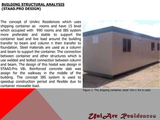
  • 37. BUILDING STRUCTURAL ANALYSIS (STAAD.PRO DESIGN) The concept of UniArc Residences which uses shipping container as rooms and have 15 level which occupied with 990 rooms and IBS system more preferable and stable to support the container load and live load around the building transfer to beam and column n then transfer to foundation. Steel materials are used as a column and beam to support the container. The connection between container and other structures which is use welded and bolted connection between column and beam. The design of this hostel was design in STAAD.Pro V8i. Reinforced concrete slab was assign for the walkway in the middle of the building. The concept IBS system is used to speedup construction period and flexible due to container moveable load. Figure 1: The shipping container, sized 12m x 3m is used.
  • 38. BUILDING STRUCTURAL ANALYSIS (STAAD.PRO DESIGN) The shipping container’s weight was 2860 kg and pay load capacity is 25 000 kg and we can’t assign the container in STAAD.Pro but we can assign the load of container on the member. 2860kg >> 28.47Kn 28.4Kn / area of container (12m x 3m) = 0.79Kn/m2 0.79Kn/m2 x horizontal length of beam + other load have to consider = …3.37.kN/m (depends on the length) Dead Load = 3.37 kN/m Dead Load =2.5kN/m (Hostel) refer to BS Code Life Load = 2.7kN/m
  • 40. Sl.No. Description UDL Load (kN/m2) Concentrated Load (kN) 1. Bathrooms and toilets in all types of buildings 2 1.8 2. Living and bed rooms 3 Office rooms in (i) Hostel, hotels, hospitals and business building with separate store 2.5 (Live Load) 2.7 (ii) In assembly buildings 3 4.5 4. Kitchens in (i) Dwelling houses 2 1.8 (ii) Hostels, hotels and hospitals 3 4.5 5. Banking halls, class rooms, X-ray rooms, operation rooms 3 4.5 6. Dining rooms in (i) Educational buildings, institutional and mercantile buildings 3 2.7 (ii) Hostels and hotels 4 2.7 7. Corridors, passages, stair cases in (i) Dwelling houses, hotels, and hostels 3 4.5 (ii) Educational, institutional and assembly buildings 4 4.5 (iii) Mercantile buildings 5 4.5 8. Reading rooms in libraries (i) With separate storage 3 4.5 (ii) Without separate storage 4 4.5 Column Stump : UC356 X 368 X 177 Column Size for building : UC356 X 368 X 153 Beam Size : UB305 X 165 X 54 Container Holder size : TUB1608012.5 Walkway : Reinforced concrete slab size 0.2 m was merged with UB305 X 165 X 54 • Bolt Connection which is use M30 to connect column and beam and M20 for container holder and container itself • Shear wall use for lift core Property of Steel Materials
  • 41. STAADPRO DESIGN Figure 2: Whole structure and the member of column and beam Figure 3: Plate surface was assign as a Shear wall for lift core. Figure 4: Bending moment of Ground floor. Figure 5: Shear force z and y direction on member.
  • 42. Figure 6: Top render view of UniArc Residences Block A and B. Figure 7: Side render view of UniArc Residences Block A and B. Table above shows the summary of displacement due to member. Table above shows the summary of Beam and Force.
  • 43. Total Applied load 1 TOTAL APPLIED LOAD ( KN METE ) SUMMARY (LOADING 1 ) SUMMATION FORCE-X = 0.00 SUMMATION FORCE-Y = -161438.24 SUMMATION FORCE-Z = 0.00 Total Reaction Load 1 TOTAL REACTION LOAD( KN METE ) SUMMARY (LOADING 1 ) SUMMATION FORCE-X = 0.00 SUMMATION FORCE-Y = 161438.24 SUMMATION FORCE-Z = 0.00 SUMMATION OF MOMENTS AROUND THE ORIGIN- MX= 4695572.67 MY= 0.00 MZ= 275171.57 MAXIMUM DISPLACEMENTS ( CM /RADIANS) (LOADING 1) MAXIMUMS AT NODE X = 1.04335E+00 7944 Y = -1.41989E+00 8173 Z = 1.01648E+00 7797 RX= -2.49647E-03 1257 RY= -1.15224E-03 7882 RZ= -1.70877E-03 1260 EXTERNAL AND INTERNAL JOINT LOAD SUMMARY ( KN METE )- JT EXT FX/ EXT FY/ EXT FZ/ EXT MX/ EXT MY/ EXT MZ/ INT FX INT FY INT FZ INT MX INT MY INT MZ SUPPORT=1 238 0.00 -6.94 0.00 0.00 0.00 0.00 0.72 -868.51 -0.30 0.00 0.00 0.00 111000 239 0.00 -6.94 0.00 0.00 0.00 0.00 18.33 -1002.71 -0.55 0.00 0.00 0.00 111000 240 0.00 -6.94 0.00 0.00 0.00 0.00 2.77 -1070.11 0.28 0.00 0.00 0.00 111000 243 0.00 -6.94 0.00 0.00 0.00 0.00 -2.20 -1311.97 1.37 0.00 0.00 0.00 111000 244 0.00 -1.74 0.00 0.00 0.00 0.00 1.59 -80.47 6.09 0.00 0.00 0.00 111000 245 0.00 -6.94 0.00 0.00 0.00 0.00 -7.04 -1877.43 -9.16 0.00 0.00 0.00 111000 246 0.00 -6.94 0.00 0.00 0.00 0.00 -0.76 -1102.06 0.65 0.00 0.00 0.00 111000 247 0.00 -6.94 0.00 0.00 0.00 0.00 -3.89 -974.29 0.25 0.00 0.00 0.00 111000 248 0.00 -6.94 0.00 0.00 0.00 0.00 0.08 -901.93 -0.18 0.00 0.00 0.00 111000 249 0.00 -6.94 0.00 0.00 0.00 0.00 6.97 -1845.73 3.19 0.00 0.00 0.00 111000 250 0.00 -6.94 0.00 0.00 0.00 0.00 -0.77 -777.01 -0.13 0.00 0.00 0.00 111000 251 0.00 -1.74 0.00 0.00 0.00 0.00 -2.76 -126.01 12.40 0.00 0.00 0.00 111000 252 0.00 -6.94 0.00 0.00 0.00 0.00 1.31 -883.08 -0.03 0.00 0.00 0.00 111000 ***TOTAL APPLIED LOAD ( KN METE ) SUMMARY (LOADING 2 ) SUMMATION FORCE-X = 0.00 SUMMATION FORCE-Y = -104016.01 SUMMATION FORCE-Z = 0.00 SUMMATION OF MOMENTS AROUND THE ORIGIN- MX= -3014467.56 MY= 0.00 MZ= -210624.92 TOTAL REACTION LOAD( KN METE ) SUMMARY (LOADING 2 ) SUMMATION FORCE-X = 0.00 SUMMATION FORCE-Y = 104016.01 SUMMATION FORCE-Z = 0.00 SUMMATION OF MOMENTS AROUND THE ORIGIN- MX= 3014467.53 MY= 0.00 MZ= 210624.92 MAXIMUM DISPLACEMENTS ( CM /RADIANS) (LOADING 2) MAXIMUMS AT NODE X = 7.50485E-01 7944 Y = -1.00336E+00 8173 Z = 7.32269E-01 7797 RX= -1.72856E-03 1257 RY= -8.23866E-04 7882 RZ= -1.11287E-03 1260
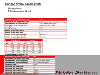
  • 44. Pile Cap Geometrical Data Pile Cap Length PCL = 3.598 m Pile Cap Width PCW = 2.500 m Initial Pile Cap Thickness tI = 0.300 m Pile Geometrical Data Pile spacing Ps = 1.500 m Pile Edge distance e = 0.500 m Pile Diameter dp = 0.500 m Pile Capacities Axial Capacity PP = 500.000 kN Lateral Capacity PL = 100.000 kN Uplift Capacity PU = 300.000 kN FOUNDATION DESIGN (PILING) PILE CAP DESIGN-NODE P238 Material Properties Concrete f'c = 25.000 kN/m^2 Reinforcement fy = 460.000 kN/m^2 Concrete Cover Bottom Clear Cover CCB = 0.050 m Side Clear Cover CCS = 0.050 m Pile in Pile Cap PCP = 0.075 m Loading applied at top of cap Load Case Fx (kN) Fy (kN) Fz (kN) Mx (kNm) My (kNm) Mz (kNm) 1 0.722 -875.452 -0.304 0.000 0.000 0.000 2 0.287 -602.273 -0.265 0.000 0.000 0.000 3 1.009 -1477.725 -0.569 0.000 0.000 0.000 4 1.471 -2189.269 -0.849 0.000 0.000 0.000 Pile Cap size (in investigated direction) H = 3.598 m Pile Cap size (in investigated perpendicular direction) B = 2.500 m Piles are used to transfer a surface load to competent soil or rock layer at depth when surface layer is not adequate or not economically feasible to use. For this design spun pile type were used to build up pile cap design which merge with I-beam steel.
  • 45. _ Arrangement Reaction Pile No. X (m) Y (m) Axial (kN) Lateral (kN) Uplift (kN) 1 -1.299 -0.750 -309.036 0.232 0.000 2 -1.299 0.750 -308.922 0.232 0.000 3 0.000 0.000 -309.037 0.232 0.000 4 1.299 0.750 -309.038 0.232 0.000 5 1.299 -0.750 -309.152 0.232 0.000 Maximum bar size allowed along length # 32 Maximum bar size allowed along width # 20 Bending Moment At Critical Section = -1007.520 kNm (Along Length) Bending Moment At Critical Section = -509.797 kNm (Along Width) Pile Cap Thickness t = 0.842 m Selected bar size along length # 12 Selected bar size along width # 12 Selected bar spacing along length = 79.60 mm Selected bar spacing along width = 102.53 mm PILE CAP DESIGN CALCULATION Pile reactions: Total pile number N = 5 REINFORCEMENT CALCULATION Maximum bar size allowed along length # 32 Maximum bar size allowed along width # 20 Bending Moment At Critical Section = -1007.520 kNm (Along Length) Bending Moment At Critical Section = -509.797 kNm (Along Width) Pile Cap Thickness t = 0.842 m Selected bar size along length # 12 Selected bar size along width # 12 Selected bar spacing along length = 79.60 mm Selected bar spacing along width = 102.53 mm
  • 46. PILE CAP THICKNESS CHECK Calculated Thickness' (t) = 0.842m Check for Moment (Along Length) Critical Load Case for thickness is reported only when required thickness is more than the given minimum thickness. Critical Load Case : 4 Check for Moment (Along Width) Critical Load Case for thickness is reported only when required thickness is more than the given minimum thickness. Critical Load Case : 4
  • 47. Check for One Way Shear (Along Length) Check for One Way Shear (Along Width)
  • 48. Check for One Way Shear Check for Two Way Shear (Along Length)
  • 49. Table : The Pile cap summary for each node.
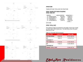
  • 50. STEEL TYPE LENGTH (m) PRICE (RM) UB 305X165X54 42322.80 48,781,843.00 UC 356X368X177 2502.72 3,316,077.00 TUB 1608012.5 21446.80 10,935,498.00 UC 356X368X153 11622.51 12,652,068.00 GRAND TOTAL COST 75,685,487.00 STRUCTURE TAKING OFF AND TOTAL COST OF STRUCTURE STEEL TAKING OFF FROM STAADPRO STEEL TAKE-OFF PROFILE LENGTH(METER) WEIGHT(KN ) ST UB305X165X54 42322.80 22368.411 ST UC356X368X177 2502.72 4345.013 ST TUB1608012.5 21446.80 8583.640 ST UC356X368X153 11622.51 17410.745 TOTAL = 52707.808 STEEL TOTAL COST The material of steel cost estimate by the length of each type of steel by follow latest CIDB market price. The table below show the grand total price of cost. Table 2.0: The total cost for structure.