Vaporizers
Download as PPT, PDF202 likes49,492 views

Vaporizers are devices that change liquid anesthetic agents into vapor and add a controlled amount of vapor to the gas flow or breathing system. They do this by utilizing concepts like vapor pressure, boiling point, and partial pressure. There are several types of vaporizers including concentration calibrated vaporizers, measured flow vaporizers, and electronic vaporizers. Key factors that affect vaporization include temperature, flow rate, volatility of the agent, and carrier gas composition. Ambient pressure changes from high altitude, hyperbaric conditions, or back pressure can impact the vaporizer's output.


Vaporizers
- 2. What is a vapour ? Vapour refers to a gas phase at a temperature where the same substance can also exist in liquid or solid
- 3. Definition VAPORIZER= Anesthetic agent delivery system OR Vapor delivery system A ‘vaporizer’ is a device that changes a liquid anesthetic agent into its vapor and adds a controlled amount of that vapor to the fresh gas flow or the breathing system.
- 4. Why vaporizer? All inhalational anesthetic agents are highly potent and toxic substances Can not be given directly It has to be given in small concentrations along with oxygen and other carrying gases
- 5. Physical principles Vapor pressure: The molecules from the liquid which exists in gaseous phase are known collectively as ‘vapor’. This vapor exerts a pressure on its surroundings which is known as ‘vapor pressure’ The pressure exerted by the vapor when in equilibrium with the liquid phase at constant temperature is called “saturated vapor pressure”.
- 6. On applying heat, more molecules enter vapor phase-> raises vapor pressure. Passing a carrier gas over the liquid causes shift to vapor phase. Vapor pressure depends only on the liquid and TEMPERATURE, not affected by ambient pressure.
- 8. Boiling point: it is that temperature at which the saturated vapor pressure is equal to the atmospheric pressure and at which all the liquid agent changes to the vapor phase. The lower the atm. pressure, lower the boiling point, for eg, at high altitudes. The most volatile agents are those with the highest SVPs.
- 10. Concentration of Gases Partial pressure(Dalton’s Law) According to this law, the total pressure of mixture of gases must equal to the sum of partial pressure of all the component gases. The partial pressure exerted by the vapor of a liquid agent depends only on the temperature of that agent. The highest partial pressure that can be exerted by a gas at a given temperature is its Vapor Pressure.
- 11. Volumes percent – it is the number of units of volume of gas in relationship to a total of 100 units of volume for the total gas mixture. The volume percent expresses the relative ratio of gas molecules(%) in a mixture where as partial pressure (mm Hg) expresses an absolute value. Anesthetic uptake and potency are related directly to partial pressure and only indirectly to volumes percent.
- 12. Latent heat of vaporization : The amount of energy that is consumed for a given liquid as it is converted to a vapor is called the ‘latent heat of vaporization’. More precisely it is the number of calories required to change 1gm or 1ml of liquid into vapor without a temperature change. Latent heats of vaporization at 200 C for halothane, enflurane and isoflurane are 35, 42 and 41 cal/g respectively.
- 13. Specific heat:Is the number of calories required to increase the temperature of 1g or 1ml of a substance by 10 C. Water is the standard with specific heat of 1cal/g/ 0C or 1cal/ml/0C. The concept of specific heat is important when a) considering the amount of heat that must be supplied to a liquid anesthetic to maintain a stable temperature when heat is lost during vaporization. b) choosing the material to construct a vaporizer.
- 14. Thermal capacity is defined as product of specific heat and mass, represents the amount of heat stored in the vaporizer body. Vaporizer construction from a substance with high thermal capacity will change temperature more slowly than one with low thermal capacity.
- 15. Thermal conductivity:Is a measure of the speed with which heat flows through a substance. The higher the value, the better the substance conducts heat. Vaporizers are made up of metals that have relatively higher thermal conductivity to minimize temperature changes when vaporizer is in use, thus thermostabilization achieved.
- 17. Splitting ratio:The ratio of bypass flow to flow to the vaporizing chamber is referred to as the "splitting ratio" and this ratio depends on a)ratio of resistances in two pathways variable/adjustable orifice present at inlet/outlet concentration dial setting. b)total flow to the vaporizer.
- 20. One implication in the above data is that concentration- calibrated vaporizers are agent specific and therefore only the particular anesthetic agent for which the vaporizer has been designed and calibrated may be safely used. For example, if an enflurane (Ethrane) vaporizer was set to deliver 1% agent but had been inadvertently filled with halothane (Fluothane) the splitting ratio would be 46: 29, yielding an actual halothane (Fluothane) vapor not of 1% but rather of 1.6%.
- 21. Classification Based on method of regulating output: Variable bypass vaporizer or concentration calibrated Measured flow vaporizer
- 22. Concentration calibrated vaporizers / Variable bypass Vaporizers calibrated by agent concentration expressed in percentage of vapor output are Concentration calibrated vaporizers/Direct reading/Dial controlled / Automatic plenum/Percentage type/Tec type vaporizers. known as
- 23. Vaporizer output is controlled by single knob / dial calibrated in Volumes percent. Located between flowmeters and common gas outlet. Not calibrated for high gas flows (O2 flush) and offers high resistance, hence not suited for use in breathing system.
- 24. They are called Variable Bypass Vaporizers because clinically useful concentrations accomplished by SPLITTING the gas flow that passes through the vaporizer – a part flows through the vaporizing chamber and the remainder flows through the bypass to the vaporizer outlet, both gas flows join downstream of the vaporizing chamber, where the gas exits at the desired concentration.
- 26. Variable bypass vaporisers Boyle’s bottle Goldman Vaporizer
- 27. Electronic vaporizers 2 types: A) A computer calculates the carrier gas flow that needs to pass through vaporizing chamber to produce desired concentration of anesthetic agent. B) Withdraws a calculated amount of liquid agent and injects into the breathing system / fresh gas flow.
- 28. The composition of the carrier gas affects vaporizer output ( VAPORIZER ABBERANCE ) in many concentration calibrated vaporizers. Most vaporizers are calibrated using Oxygen as carrier gas. Addition of nitrous oxide to carrier gas results in both temporary (decrease output) and long lasting effect (increase or decrease, depending on the construction of vaporizer).
- 29. Measured flow vaporizers Kettle type / flow metered / flowmeter controlled vaporizer systems. Use a measured flow of carrier gas–oxygen, to pick up anesthetic vapor. No longer available for sale.
- 31. Copper Kettle
- 32. Depending on method of vaporization 1. Flow over 2. Bubble through 3. Injection Depending on temperature compensation None, By supplied heat By flow interaction
- 33. A)flow over: a stream of carrier gas passes over the surface of the liquid. Most commonly used. Efficiency of vaporization enhanced by increasing the area of carrier gas-liquid interface by - using baffles or spiral tracks to lengthen the pathway of gas over liquid. - using wicks that have their bases in the liquid. The liquid moves up the wick by capillary action.
- 34. B) bubble through: the carrier gas is bubbled through the volatile liquid, further increasing the gas-liquid interface. C) injection: vapor concentration controlled by injecting a known amount of liquid anesthetic agent (from a reservoir in the vaporizer or from the bottle of agent) into a known volume of gas.
- 37. Temperature compensation As a liquid is vaporized, energy in the form of heat is lost. As the temperature of the liquid decreases, so does the vapor pressure. Two methods employed to maintain a constant vapor output with fluctuations in liquid anesthetic temperature: -thermocompensation -supplied heat
- 39. A) mechanical thermocompensation By altering the splitting ratio so that the percentage of carrier gas that is directed through the vaporizing chamber is increased or decreased by the thermal element. As the vaporizer cools the bypass flow is restricted more carrier gas passes through the vaporizing chamber. The opposite occurs if the vaporizer becomes too warm.
- 40. B) supplied heat An electric heater used to supply heat to a vaporizer and maintain it at a constant temperature. C) computerized thermocompensation The amount of agent injected into the breathing system or fresh gas flow may be altered. Computerized control of the amount of carrier gas that flows through the vaporizing chamber.
- 41. Depending on the location Outside the breathing system (VOC) Inside the breathing system. (VIC) Depending on the specificity Agent specific Multiple agents
- 42. Another classification Plenum vaporizers: positive pressure applied at the inlet of the vaporizer. Eg. Boyle vaporizers, copper kettle, fluotec Mark 2 and 3. Inhalers or draw over vaporizers: negative pressure applied at the outlet. Eg. EMO vaporizer, Oxford miniature inhaler, Tecota Simple vaporizers Eg. Goldman, Rowbotham vaporizer.
- 44. Factors affecting vaporization of a liquid Flow through the vaporizing chamber Efficiency of vaporization Temperature Time Gas flow rate Carrier gas composition Volatility Area of contact with the liquid.
- 46. Effects of altered barometric pressure Most vaporizers are calibrated at sea level (standard atmospheric pressure). Anesthetic agents with low boiling points are more susceptible to variations in barometric pressure. ASTM machine standard requires that the effects of changes in ambient pressure on vaporizer performance be stated in operation manuals.
- 47. High altitude (Hypobaric conditions) Consider a variable bypass vaporiser for halothane is being used at an altitude of 10,000 feet above sea level. Ambient pressure = 500 mmHg. SVP of halothane = 243 mmHg 243 = 48.6% of atmospheric ----------- 500 pressure at that altitude.
- 48. Splitting ratio for a setting of 1% halothane in a variable bypass vaporiser is 46:1. Suppose a total fresh gas flow of 4,700 ml is on flow. 100 ml of this will pass through the vaporiser where halothane now represents 48.6% of the atmosphere in the vaporising chamber.
- 49. SVP = agent vapour(xml) ___________ _____________________ total pressure Carrier gas (y ml) + Agent vapour (X ml) 243 = X ml ___________ _________ 500 100 + X Solving this, X = 94.55 ml ≅ 95 ml
- 50. Thus, 95 ml of vapour + 100 ml of carrier gas = 195 ml. 195 ml + 4,600 ml bypass flow = total flow of 4795 ml, Halothane concentration = 95/4795 = 1.98 % ≅ 2%.
- 51. Set concentration – 1% Delivered concentration – 2% Is this a worry?
- 52. 2% of 500 mmHg ambient pressure (altitude of 10,000 feet) is 10 mmHg . 1% of halothane at sea level is 7.6 mmHg. BRAIN RECOGNISES PARTIAL PRESSURE! 10 mmHg = 1.3 times halothane at sea level. The increase in the partial pressure is only 1.3 times.
- 54. High atmospheric pressure: this causes decrease in vaporizer output in both partial pressure and volumes percent because increased atmospheric pressure changes the density of gases more resistance to flow through vaporizing chamber. At 2 atm, the concentration in volume percent is halved But clinically, anesthetic potency output expected for any given vaporizer setting changes little, even though volumes percent may be altered considerably.
- 55. Hyperbaric Environment Let us use the halothane vaporiser at 3 atmospheric pressures with a fresh gas flow of 4,700 ml.
- 56. Hyperbaric Environment Let us use the halothane vaporizer at 3 atmospheric pressures with a fresh gas flow of 4,700 ml. If it is set at a dial concentration of 1%, since the splitting ratio is 46:1, 100 ml of the fresh gases will flow through the vaporiser as a carrier gas flow.
- 57. SVP Total pressure = 243 Agent vapour (x ml) Carrier gas + Agent vapour x ml
- 58. SVP Agent vapour (x ml) Total pressure = 243 Carrier gas + Agent vapour x ml _________________ _________________________ A total of 112 ml from the vaporiser will join the bypass flow to make a 2280 = 100 ml + x ml total of 4712 ml to give a halothane concentration of 0.25%. On solving the equation, x = 11.92 ml ≅ 12 ml
- 59. But, the partial pressure of halothane delivered would be 0.25% x 2280 mmHg = 5.7 mmHg. This is 0.75 times the partial pressure achieved at sea level with a setting of 1%.
- 60. The partial pressure of halothane delivered would be 0.25% x 2280 mmHg = 5.7 mmHg. This is 0.75 times the partial pressure achieved at sea level with a setting of 1%. ∴At 3 atmospheres, concentration of halothane vapour is 0.25%. But, actual partial pressure is 0.75% of that at sea level.
- 61. Low Altitudes Lower Concentration But Only Slightly Lower Partial Pressure
- 62. Low atmospheric pressure: a concentration calibrated vaporizer increases output slightly under hypobaric conditions by altering the splitting ratio. The high resistance pathway through vaporizing chamber offers less resistance under such conditions. It will deliver approximately the same partial pressure but increasing concentrations measured as volume percent. With measured flow vaporizer the delivered partial pressure increases and volumes percent increases even more if the surrounding pressure is lowered.
- 64. Effects of intermittent back pressure Pumping effect – increase the output Pressurizing effect – decrease the output Sources of back pressure 1. during assisted/controlled ventilation, the positive pressure generated during inspiration is transmitted from the breathing system back to machine and vaporizer. 2. use of O2 flush valve, the output from O2 flush enters the circuit downstream of vaporizers and its activation produces high pressure.
- 65. Pumping effect When resistance is applied to the outlet of the anesthetic machine, as during assisted or controlled ventilation, there is an increase in the anesthetic gas pressure which is transmitted back to the vaporizer. This adds to the vaporizer output to increase the final vapor output. This change is most pronounced when there is less agent in the vaporizing chamber, carrier gas flow is low, high and frequent pressure fluctuations, low dial setting.
- 66. By pass channel FGF Vaporising chamber
- 67. By pass channel FGF Vaporising chamber By pass channel By pass channel FGF FGF Vaporising chamber
- 68. By pass channel FGF Vaporising chamber By pass channel FGF Vaporising chamber
- 69. By pass channel FGF Vaporising chamber
- 70. By pass channel FGF Vaporising chamber
- 71. S
- 72. Pressurizing effect: the output of some vaporizers decreases when there is back pressure. This effect is greater with high flows, large pressure fluctuations and low vaporizer settings. The changes in vaporizer output caused by the pumping effect is usually greater in magnitude than those associated with the pressurizing effect. Pressurizing effect – with high gas flows Pumping effect – with low gas flows
- 75. Effects of Rebreathing Rebreathing causes a difference between the vaporizer setting and the inspired concentration. Only an agent analyser can provide an accurate value for the inspired agent concentration.
- 76. Sequence of vaporizers In modern anesthesia machines an interlocking system called the SELECTATEC system incorporated so that only one vaporizer is in use at a time. If selectatec system is not installed the sequence of vaporizer should be such that least potent agent must be placed upstream and most potent agent last in the sequence.
- 77. How much liquid agent does a vaporizer use per hour? Ehrenwerth and Eisenkraft gives the formula 3 X Fresh gas flow(L/min) X Volume % = ml liquid used /hr This formula is based on the fact that typically 1 ml of liquid volatile agent yields about 200ml of vapor
- 78. Features of ideal vaporizers It should be simple, safe, satisfactory and more practical. It should have low resistance to gas flow. It should be temperature compensated for uniform vaporization.
- 79. It should have flow stability and should permit a relatively constant concentration at different flow rates of the carrier gas. It should permit precise, accurate, controllable and predictable delivered concentration of the vapor to the patient. The performance of the vaporizer should not be affected by changes in fresh gas flow, volume of liquid, ambient temperature and pressure, decrease in temperature due to vaporization and pressure fluctuation due to mode of respiration.
- 80. It should be light weight and small liquid requirement. Construction should be corrosion and solvent resistant. It should have good quality control. The case of the vaporizer is usually made of copper which is a good heat sink and it consists of bypass channel and vaporization chamber.
- 81. Specific vaporizers Boyle’s bottle:Mainly for ether and trichloroethylene. Flow over or bubble through type. No temperature compensation or calibration. Multiple agent type. Agitation of vaporizer and splashing may also increase the concentration most probably due to a little warming of the liquid
- 83. Goldman vaporizer Single vaporizer for use as draw over or within the closed circuit system was designed by Goldman. It has no temperature compensation. Maximum concentration never exceeds 2% irrespective of total gas flow. It is a low efficiency vaporizer except during splashing when over 5% of concentration of halothane can be obtained. By incorporating a wick made of blotting paper or by employing two vaporizers in series output may be increased.
- 85. EMO vaporizer It was introduced by Epstein, Macintosh and Oxford in 1952 Variable bypass and flow over (with wick) type of vaporizer, temperature compensated and may be used for vaporization of ether, chloroform, halothane and trichloroethylene. There is a thermocompensator small metal bellows containing a liquid at the vaporising chamber outlet
- 87. Copper kettle vaporizer Described by Lucien Morris in 1952 In this a measured flow of oxygen is allowed to bubble through the anesthetic liquid Separate supply of oxygen form an extra flowmeter Flow of oxygen through the copper kettle and flow of fresh gas should be calculated. If the fresh gas flow is reduced the sudden high anesthetic concentration may be dangerously delivered to the patient.
- 89. Tec 2 It is a plenum vaporizer flow over with wicks. It is temperature compensated by flow alteration and agent specific Bimetallic strip for temperature compensation is present within the chamber. The control knob is calibrated from off position to 4% in 0.5% increments. A pressuring valve has been designed to prevent pumping effect
- 91. Tec 3 Its of variable bypass and flow over type. Its both temperature and flow compensated. Its used for halothane, isoflurane, enflurane and sevoflurane Bimetallic strips provide temperature compensation. It has a larger bypass. It is more reliable and accurate The dial has 0.5% to 5% graduation with a lock.
- 92. The tube leading to vaporizer chamber is longer and wicks have been removed from the area of vaporizer near the inlet. Tipping leads to increased concentration and reversed flow leads to increased output
- 94. Tec 2 Tec 3 Vaporizing chamber Round in shape with capacity of 150ml Capacity is around 70ml Bypass Only one Two Effect of back pressure Increased output Negligible Accuracy Less More compared to tec 2 Calibration 4% 5% Bimetallic strip Present in chamber Present in the bypass
- 95. Tec 4 Its of variable bypass, flow over with wicks variety. Its is temperature compensated and agent specific This has similar features of Floutec3. Added features are that if it is accidentally inverted, the liquid agent will not spill into the bypass. It incorporates an interlocking facility of push rod mechanism, so that two vaporizer mounted side by side are not turned on at the same time
- 97. Tec 5 The wick assembly is constituent of a hollow cloth tube held open by a steel wire spiral, which is wound into a helix within the vaporizer. Bimetallic strip which acts as a thermostat. It has a keyed filling system. Greatest accuracy is at gas flow of 5L/min, 150 C and 350C and dial settings less than 3%. At higher flow rates and at higher dial settings there is a decrease in output.
- 99. Tec 4 Tec 5 Vaporizing chamber Smaller capacity Larger capacity Quantity 135ml when dry and 100ml when wicks are wet 300ml when dry and 225ml when wicks are wet Thermostat Present in centre of vaporizer Present at the base Concentration control dial Complicated Easier and simpler Accuracy Less accurate More accurate Service Annual Triannual
- 100. Tec 6 It is concentration calibrated, gas vapor blender, thermocompensation by supplied heat, agent specific and plenum vaporizer. The concentration dial is at the top and is calibrated from 1% to 18%, in graduation of 1% upto 10% and 2% from 10% to 18%. The filler port is in front and is designed that only a Desflurane specific bottle can be inserted into it
- 103. The amber warm up LED indicator is connected to the main power. The green operational LED is illuminated, indicating that the vaporizer has reached its operational temperature. The red no output LED flashes with an auditory alarm of repetitive tones, if the vaporizer is not able to deliver the vapor
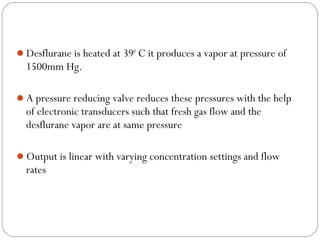
- 104. Desflurane is heated at 390 C it produces a vapor at pressure of 1500mm Hg. A pressure reducing valve reduces these pressures with the help of electronic transducers such that fresh gas flow and the desflurane vapor are at same pressure Output is linear with varying concentration settings and flow rates
- 105. Tec 7 These are used for halothane, enflurane, isoflurane and sevoflurane There is a release button that must be pushed in before the vaporizer can be turned on at the rear of the dial. A locking lever connected to the control dial is provided so that the vaporizer cannot be turned on until it is locked on the manifold provided at the rear
- 106. Greater accuracy is fresh gas flow of 5l/min and dial setting of 3%. At higher flow rates and higher dial settings there is a decrease in output. The innovative non spin system in the Tec 7 vaporizer limits the movement of liquid agent, if the vaporizer is tilted or inverted.
- 107. Drager vaporizer It is of variable bypass, flow over (with wicks), temperature compensated and agent specific. Output is independent of fresh gas flows in the range of 0.3 to 15L/min, When vaporizer is turned on, gas partly enters the vaporizing chamber and bypass channel.
- 108. Gas which is saturated later mixes with bypass gas and then pass on to the outlet. Temperature changes will be compensated by the bypass cone. It is calibrated using air as the carrier gas In cases of 100% O2 the output conc is 5-10% higher and in 30% and 70% N2O it is 5-10% lower. Reversed flow has no effect on output
- 110. Drager D-Vapor Only for Desflurane. Electrically powered. Concentration range 2% - 18%. Higher than 12% are in inverted order. Capacity 300ml D-Vapor filling system (Saf-T-Fil System) is located on the front of the vaporizer along with display and alarm indicators (LED).
- 112. The delivered desflurane concentration is determined by the relationship b/w the bypass resistance and flow control cone, which is determined by control dial setting. Carrier gas composition will affect the vaporizer output, calibrated using O2. The output reduced when air/N2O used. Performance better at 18-300C. Cellular phones should not be used within 10m of the vaporizer.
- 113. Aladin vaporizer This is designed agents desflurane, isoflurane, sevoflurane, halothane and enflurane. Concentration calibrated, flow over and automatic thermocompensation The agent is in a portable cassette that is inserted into a slot in the anesthesia machine. The control dial is on the machine next to where the cassette is placed. A magnetic sensor identifies the cassette.
- 116. The cassette is color coded and magnetically coded Fresh gas enters the vaporizer and is split between the bypass flow that is in the machine and the vaporizer chamber Wicks in the chamber increase the surface area. The flow at the outlet of the chamber is controlled by the central processing unit (CPU) in the machine.
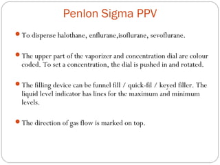
- 117. Penlon Sigma PPV To dispense halothane, enflurane,isoflurane, sevoflurane. The upper part of the vaporizer and concentration dial are colour coded. To set a concentration, the dial is pushed in and rotated. The filling device can be funnel fill / quick-fil / keyed filler. The liquid level indicator has lines for the maximum and minimum levels. The direction of gas flow is marked on top.
- 119. Gas enters the vaporizer and is split into two streams. In zero-lock position, the bypass remains open, but the vaporizing chamber is isolated. If the zero lock port is open, the gas flows through a spiral tube into vaporizing chamber which contains stainless steel wick. Gas saturated with vapor exits the chamber through vapor control orifice whose size is determined by the control dial, then joins the bypass gas and flows to the outlet.
- 120. Temperature compensation provided by liquid-filled expansion bellows controlling a variable resistance valve in the bypass. Accurate at 15-350C. The output is high at low flows, higher temperature, with N2O & reversed gas flow. Calibrated every 3-6 months, major overhaul every 5 yrs. The exterior is cleaned with a dry cloth.
- 121. Penlon Sigma Delta For halothane, enflurane, isoflurane, sevoflurane. Improved version of Penlon Sigma PPV. Temperature compensation is by means of a Thermostat in the bypass. Calibrated with 100% oxygen. N2O and air in the carrier gas will decrease the output. Operating temperature 15-350C, FGF 0.2-15L/min. A steady back pressure 10-15kPa reduce the vaporizer output. Its flow direction sensitive. Output inaccurate if flow is reversed.
- 123. Hazards of Sigma Delta: may malfunction if exposed to excessively high temperatures. The control dial should be at 0 and the vaporizer upright while filling and transport. If transported in open position, the vaporizer must be flushed with 5L/min flow of gas for atleast 10min before use. If tipped or inverted during transport, control dial set to maximum output and run at 5L/min for 10min prior to use. Calibration done using suitable agent gas analyzer. Major overhaul every 10 yrs.
- 124. Penlon Sigma Alpha Electrically powered, for DESFLURANE. Control dial is in the front, below which is the display screen that shows Warm-up, Standby, Inuse, Battery in use messages. Warmup takes approx 2min, no vapor output during that period. The agent consumption mechanism allows the user to quantify the volume of desflurane used for each case. Liquid desflurane flow is measured by a liquid flow sensor. Capacity 330ml.
- 125. Calibrated with pure O2. Designed to use at temp 15-300C, flow range 0.5-12L/min Hazards : excessive electronic noise caused by a device such as electrosurgery unit may adversely interfere with vaporizer function. - electromagnetic interference
- 127. Blease Datum Available for halothane, enflurane, isoflurane, sevoflurane. Agent specific coloured label is on front below the concentration dial which is pushed inwards and rotated counterclockwise to set concentration. The dial should not be set b/w zero and first setting. Filling device: funnel fill, keyed filler, sevo can have quick-fil.
- 128. Gas enters the vaporizer and is split into two streams, one passing through bypass, other through vaporizing chamber. When vaporizer is turned ON, zero lock valve opens, & gas passes through a spiral tube to minimize the effects of intermittent positive pressure ventilation, then through chamber that contains a main & a coil wick. Gas saturated with vapor exits through vapor control valve whose size determined by dial setting. Temp compesation is provided by a mechanism with its base in the vaporizing chamber, connected to variable bypass valve.
- 129. Calibrated using air. O2 will increase the output slightly. Excessive output may occur if vaporizer is moved suddenly during use. It should be drained prior to transport. Changes in atmospheric pressure do not usually affect the output, but altitudes greater than 1500m may require a correction factor. Exterior cleaned with clean, damp cloth. Halothane vaporizers drained at regular intervals to prevent thymol buildup.
- 132. IN-SYSTEM VAPORIZERS The vaporizing chamber is a simple reservoir of glass with or without the means of temperature compensation. There are two ways that gas flows through a vaporizer: push through and draw over. Eg. Oxford Miniature Vaporizer (OMV) for halothane, enflurane, isoflurane, sevoflurane. It is designed for continuous flow rates b/w 3 and 8L/min or drawover rates b/w 4 and 10L/min and ambient temperatures b/w 18 and 280 C. Not recommended for use within closed system – rapid anesthetic overdose may result, their performance will deteriorate with time because water condenses on the wick.
- 134. Filling Systems There are a number of different filling systems available: Funnel filling system, Keyed filling system, Quick –Fil system, Easy-Fil system, and Desflurane filling system. ASTM machine standard recommends that a vaporizer should be designed for a single agent fitted with a permanently attached, agent specific device to prevent accidental filling with the wrong agent.
- 136. Funnel filling system Vaporizer component – funnel and cap Filling: the filler cap is removed by turning it counterclockwise and agent is poured into the filling port. This can be converted to an agent specific keyed filling system by addition of an adaptor that screws into the vaporizer filler. Bottle component – colour coded adaptor with screw thread and skirt with slots that matches the projections on Bottle collar.
- 137. Keyed filling system Vaporizer component – vaporizer filler receptacle (filler socket or block, vaporizer filler unit, fill and drain system) permits only the intended bottle adaptor to be inserted. There may be a single port for both filling and draining or two ports, upper one for filling and lower for draining. An air vent may be located on the vaporizer which must be opened prior to filling to prevent air lock.
- 138. Bottle component – colour coded collar attached securely to the neck. Colours: Red – halothane Yellow – sevoflurane Purple – isoflurane Orange – enflurane Bottle adaptors (adaptor tubes or assemblies, tube adaptors, filler tubes) are also colour coded. At one end is the connector with screw thread and skirt which extends beyond. Other end is the male connector that fits into the vaporizer filler receptacle. A short length of plastic tubing with two inner tubes connects the ends, allows the bottle to be held higher or lower than the vaporizer
- 139. Bottle adaptors
- 140. The male connector (key, probe, tube block, filler plug, male adaptor) on the adaptor consists of a rectangular piece of plastic with a groove on one side and two holes on another surface. The groove is in different locations depending on the agent to be used. The larger hole is for the agent to enter or leave the vaporizer, the smaller hole is for air to leave the vaporizing chamber.
- 141. Filling – bottle adaptor screwed onto the bottle. Vaporizer turned off, the plug removed. The filler block is inserted, retaining screw tightened, filler valve (vent) opened and the bottle held higher than the filler receptacle so that liquid enters the vaporizer. Draining – the bottle is held below the vaporizer receptacle, drain (spool) valve is opened.
- 143. Problems with keyed filling system1. Liquid can leak if the device that holds the keyed component into vaporizer is not tight. 2. Vapor can leak out if the fill or drain valve is not closed. 3. Misalignment of the filling channel and the air channel between the filler and vaporizer will make it difficult to fill the vaporizer.
- 144. Quick-fil system is used for only Sevoflurane. The vaporizer filler has a screw-on cap. Filler neck has 3 grooves that can accept only a special filler device, which comes attached to the bottle. The bottle has a permanently attached agent specific filler device that has 3 ridges that fits into the slots in the filler. A valve prevents liquid from draining when the bottle is inverted but not inserted into the vaporizer. Filling : the bottle is pushed into the vaporizer component as far as it will go and held firmly in place. This will open the valve and allow liquid agent to flow into the vaporizer. Draining : the drain attachment is fitted to the bottom to which the bottle is inserted.
- 145. Easy-fil system : used in all Tec-7 vaporizers. The vaporizer has a cap with a tool that is used to open and close the drain on the filler. The filler channel has 2 keys (ridges) that fit into grooves on the bottle adapter. The bottle nozzle is inserted into the filler block, aligning the adaptor grooves with projections in the filler block. Adv: they are used for filling, draining and storage of anesthetic agent. They also reduce air pollution and prevent water and other contaminants entering the vaporizing chamber.
- 148. Desflurane filling system : the bottle has a crimped-on adaptor that has a spring loaded valve that opens when the bottle is pushed into the filling port on the vaporizer. To fill the Tec 6 vaporizer, the bottle is fitted to the filler port and pushed up against the spring, then rotated upward and held in this position while filling. Once filled, the bottle is rotated downward and removed from the vaporizer. If the “O” ring on the bottle is damaged or missing, agent may leak during filling.
- 149. Incorrect filling of vaporizer They should neither be overfilled nor underfilled. Tilting the vaporizer or the anesthetic machine may result in liquid anesthetic reaching the anesthesia gas outlet causing lethal concentration in the breathing system To avoid the filling of vaporizer with a incorrect agent KEYED FILLING devices are used
- 150. Vaporizer Mounting System Permanent mounting and Detachable mounting Permanent means it requires tools to remove or install a vaporizer. Advantages are: vaporizers will not be dropped or abused, leaks will be less
- 153. Disadvantages are that machines must have enough mounting locations to accommodate all the vaporizers Any location that does not have an attached vaporizer will need to be protected to prevent gas leaks
- 154. Detachable means mounting system that allow the vaporizer to be moved by the user without any tools. The Selectatec system is the most widely used Advantages - anesthesia machine can have fewer mounting locations allowing a more compact machine, vaporizers can be easily removed and replaced even during a case (malignant hyperthermia). Disadvantages - leaks, partial or complete obstruction to gas flow and failure to deliver anesthetic vapor may occur.
- 155. Safety features of modern vaporizers Keyed filling system Low filling port Secured vaporizers (less ability to move them minimizes tipping) Interlock devices or vaporizer exclusion systems – prevent more than one vaporizer from being turned ON at a time.
- 156. Hazards of modern vaporizers Incorrect agent – if an agent of high potency or volatility is used in a vaporizer intended for an agent of low potency or volatility, a dangerously high concentration may be delivered. The vaporizer must be completely drained and all liquid discarded. Gas should be allowed to flow through it until no agent can be detected in the outflow.
- 157. Tipping – liquid from the vaporizing chamber may get into the bypass or outlet high concentration will be delivered when the vaporizer is first used. Prevented by keeping the vaporizer in off/travel position while movement. Overfilling – liquid agent may enter the fresh gas line, and lethal concentrations may be delivered, or no output due to complete vaporizer failure. Agent specific filling devices prevent overfilling.
- 158. Reversed flow – increases output. Leaks – affect fresh gas composition and flow, pollutes OR environment. - common causes of leak: failure to replace or adequately tighten the filler cap, vent not closed or the plug not replaced/ tightened in keyed filling system, vaporizer not mounted properly, inlet / outlet connection is loose/broken. - with a leak in the vaporizer, the machine will often function normally until the vaporizer is turned on. At that point, FGF is lost through the leak.
- 159. Physical damage Vapor leak into the fresh gas line – can cause a sensitised individual to react to halogenated agent or trigger malignant hyperthermia. Contaminants in the vaporizing chamber Obstruction to fresh gas flow due to problems in mounting system Interlock malfunction Concentration dial in wrong position
- 160. Disposing of liquid anesthetics By the use of an evaporator – the liquid is allowed to evaporate and the vapor is removed by the vacuum system.
- 161. Conclusion Inhalational anesthetic agent is an integral part of “balanced anesthesia”. Hence its important to know functioning and the working principle of “vaporizer”, the device intended to deliver vapors of inhalational agent.
- 163. THANK YOU