Vertical Screw Conveyor - Design Project
29 likes10,499 views

This document describes the design of a vertical screw conveyor. It includes the selection of a JHS400 screw to transport cement vertically over 3.15 meters. A 1.4552 kW motor operating at 1425 rpm is chosen to power the conveyor. Three A-section V-belts running over pulleys with diameters of 125mm and 250mm are selected to transmit power from the motor to the screw. Gears and chains are also included in the drive mechanism with specified transmission ratios. The shaft, keys, bearings and clutch are designed. Material selections are made for the pulleys, V-belts and other components. Dimensions and specifications are provided for each designed part.


![14
Figure 4.2 – No: of teeth vs. Involute factor Y
Material selection,
Material selected = Alloy Steel (SNCM439) [4.1]
Tensile strength ( 𝜎ut) = 980 N/mm2
Allowable Static Stress ( 𝜎o) =
σ 𝑢𝑡
3
=
980
3
= 326.6667 N/mm2
Strength Factor,
Gear 1, Gear 2,
𝜎o1 = 𝜎o x 0.133 𝜎o2 = 𝜎o x 0.161
= 43.4467 N/mm2 = 52.5933 N/mm2
Here the Strength factor for G1 is less than that of G2
𝜎o1 < 𝜎o2
∴ the rest of the calculations are done to the G1.](https://image.slidesharecdn.com/mex5277miniproject-171012134943/85/Vertical-Screw-Conveyor-Design-Project-19-320.jpg)

![16
Figure 4.3 – Values of Deformation Factor C (kN/m) for Dynamic load
W1 =
21×𝑉×(𝑏.𝐶+ 𝑊𝑇1)
21×𝑉+ √𝑏.𝐶+ 𝑊𝑇1
=
21×3.7306×(9.8419×952+ 416.176)
21×𝑉+ √9.8419×952+ 416.176
= 4344.35 N
∴ Dynamic Tooth load (WD) = WT + W1
= 416.176 + 4344.35
= 4760.5247 N
For Alloy steel, Hardness = 300 BHN (using Hardness Table)
[4.2]
∴ Static Tooth load (Ws) = 𝜎e x b x π x m x y where, 𝜎e = 17.5 x Hardness
= (17.5 x 300) x 9.8419 x π x 4 x 0.133
= 85989.7891 N
For Safety,
Ws ≥ WD
∴ the condition satisfies for the obtained values](https://image.slidesharecdn.com/mex5277miniproject-171012134943/85/Vertical-Screw-Conveyor-Design-Project-21-320.jpg)


![23
Using Beam Calculations
[6.1]
RAV = 386.971 N
RBV = 229.029 N
RAH = 39.086 N
RBH = 112.914 N
The Resulting Bending Moment for pt
A and D,
Resultant Bending Moment at A
= √ 𝑀𝐴𝑉
2
+ 𝑀𝐴𝐻
2
= 14000 N.mm
Resultant Bending Moment at D
= √ 𝑀 𝐷𝑉
2
+ 𝑀 𝐷𝐻
2
= 11490.7253 N.mm
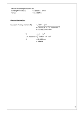
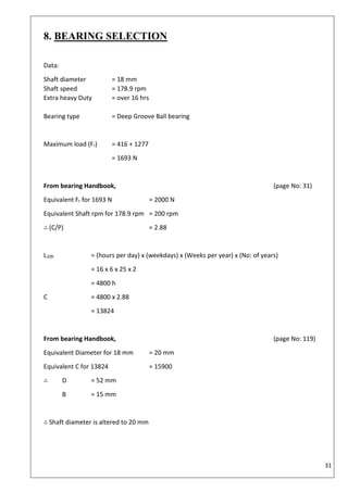
Maximum bending moment is at D,
Bending Moment at D= 14000 N.mm
Assuming same torque = 20.8088 Nm
Figure 6.3 – Bending moment diagram](https://image.slidesharecdn.com/mex5277miniproject-171012134943/85/Vertical-Screw-Conveyor-Design-Project-28-320.jpg)
![24
Material selection
Alloy steel
Km = 2 Shear stress (𝜏) = 0.3 x (Yield stress)
Kt = 1.5 = 147 MNm-2
Yield stress = 490 MNm-2 stress (𝜎) = 0.6 x (Yield stress)
= 294 MNm-2
Diameter Calculations
Equivalent Twisting moment (Te) = √(𝐾 𝑚 × 𝑀)2 + (𝐾𝑡 × 𝑇)2
= √(2 × 14000 × 10−3)2 + (1.5 × 20.8088)2
= 41.9317 Nm
Te =
𝜋
16
× 𝜏 × 𝑑3
41.9317 = 𝜋
16
× 147 × 106
× 𝑑3
d = 11.3257 mm
Equivalent Bending moment (Me) =
1
2
[(𝐾 𝑚 × 𝑀) + 𝑇𝑒]
= 14020.9659
Me =
𝜋
16
× 𝜎 × 𝑑3
14020.9659 = 𝜋
16
× 294 × 106
× 𝑑3
d = 7.8608 mm
taking the larger of the two values,
d = 11.32 mm
≈12 mm](https://image.slidesharecdn.com/mex5277miniproject-171012134943/85/Vertical-Screw-Conveyor-Design-Project-29-320.jpg)


![27
Using Beam Calculations
[6.1]
RAV = 165.29 N
RCV = 1858.286 N
RAH = 45.314 N
RCH = 623.314 N
The Resulting Bending
Moment for pt
B and C,
Resultant Bending Moment at
B = √ 𝑀 𝐵𝑉
2
+ 𝑀 𝐵𝐻
2
= 7712.4428 N.mm
Resultant Bending Moment at
C = √ 𝑀 𝐶𝑉
2
+ 𝑀 𝐶𝐻
2
= 87502.7551 N.mm
Figure 6.6 – Bending moment diagram](https://image.slidesharecdn.com/mex5277miniproject-171012134943/85/Vertical-Screw-Conveyor-Design-Project-32-320.jpg)


![32
Equivalent bending stress (𝜎𝑒𝑞) =
16
𝜋𝑑3 [(𝐾𝑏 𝑀) + √(𝐾𝑏 𝑀)2 + (𝐾𝑡 𝑇)2]
=
16
𝜋203
[(1.5 × 87502) + √(1.5 × 87502)2 + (1 × 83.235)2]
= 167.1165 N.mm-2
∴ 𝜎𝑏.𝑚𝑎𝑥 > 𝜎𝑒𝑞
Torsional stress (𝜏 𝑒𝑞) =
16
𝜋𝑑3 √(𝐾𝑏 𝑀)2 + (𝐾𝑡 𝑇)2
=
16
𝜋203 √(1.5 × 87502)2 + (1 × 83.235)2
= 83.5583 N.mm-2
∴ 𝜏 𝑏.𝑚𝑎𝑥 > 𝜏 𝑒𝑞
∴ we can conclude that the material and the diameters are safe.](https://image.slidesharecdn.com/mex5277miniproject-171012134943/85/Vertical-Screw-Conveyor-Design-Project-37-320.jpg)


Vertical Screw Conveyor - Design Project
- 1. MACHINE DESIGN MEX5277 VERTICAL SCREW CONVEYOR NAME : P. A. HEWAPATHIRANA REGISTER NUMBER : 613344004 DATE OF SUBMISSION : 22/09/2017 CENTER : COLOMBO
- 2. i Table of contents List of Illustration ii Introduction iii Aim and Objective iv Specifications iv 1. Design Layout 1 2. Motor Selection 3 3. Belt and Pully Design 6 4. Gear design 13 5. Bevel gear design 19 6. Shaft design 22 7. Keyway design 29 8. Bearing selection 31 9. Clutch 33 References 35
- 3. ii List of Illustrations Figure 1.1 – design view of the Vertical screw conveyor 1 Figure 1.2 a – Rendered View of the Gear Box 1 Figure 1.2 b – Top view and side view 1 Figure 1.3 – Rendered View of the Screw conveyor and Section View 2 Figure 2.1 – JHS400 screw specifications 3 Figure 3.1 – Selection of V-belt cross section 6 Figure 3.2 – Service factor for drives 7 Figure 3.3 – Pully arrangement 7 Figure 3.4 – A section V-belts 8 Figure 3.5 – Power correction factors for belt pitch length 8 Figure 3.6 – Power correction factor for Arc contact 9 Figure 3.7 – Pulley belt arrangement 10 Figure 4.1 – Gear arrangement 13 Figure 4.2 – No: of teeth vs. Involute factor Y 14 Figure 4.3 – Values of Deformation Factor C (kN/m) for Dynamic load 16 Figure 4.4 – terms used in a gear 18 Figure 6.1 – Shaft design 22 figure 6.2 – WD components 22 Figure 6.3 – Bending moment diagram 23 Figure 6.4 – Shaft design 24 Figure 6.5 – Forces acting on gear 26 Figure 6.6 – Bending moment diagram 27 Figure 7.1 – terms in key 29
- 4. iii INTRODUCTION Generally, conveying is accomplished by a combination of mechanical, inertial, pneumatic, and gravity forces. Application of screw conveyors can be seen almost in every industry nowadays. Conveyors utilizing primarily mechanical forces are screw, belt, and mass conveyors. Screw conveyors are widely used for transporting and elevating particulates at controlled and steady rates. They are used in many bulk materials applications in industries ranging from industrial minerals, agriculture (grains), pharmaceuticals, chemicals, pigments, plastics, cement, sand, salt and food processing. The main reason why the screw conveyors are popular because they can be used for uniform and continuous supply of various materials in manufacturing machinery and transport devices in many industries as stated above. So it is a very effective way of elevating bulk materials. Some advantages of Vertical Screw Conveyors are, • Ideal for handling dry to semi-fluid materials • Capacities up to 6,000 cubic feet per hour. • Ability to elevate bulk materials up to 30-feet without use of internal bearings. • Totally enclosed design for dust and vapor-tight requirements. Since they operate over a wide range of speeds and angles of elevation up to the vertical. In this mini project, we have focused on and designed a Vertical screw conveyor which is fully enclosed.
- 5. iv AIM To design a Vertical screw conveyor to transport material to a higher elevation from ground level. OBJECTIVE • Selecting the necessary material to be transported vertically. • Designing the vertical screw conveyor. • Obtaining the power required for the design and selection of an appropriate motor. • Design the drive mechanism. • Design the gear box. • Design the shaft and selection of keys. • Selection of bearings. • Design a suitable clutch. SPECIFICATIONS Transport material : Cement For a higher transfer rate of the selected material (Cement), Selected Screw : JHS400 ∴ pitch of the screw : 350 mm ∴ Vertical screw conveyor height : 3.15 m Speed of the screw : 60 rpm
- 6. 1 1. DESIGN LAYOUT Figure 1.1 – design view of the Vertical screw conveyor Figure 1.2 a – Rendered View of the Gear Box Figure 1.2 b – Top view and side view
- 7. 2 Figure 1.3 – Rendered View of the Screw conveyor and Section View
- 8. 3 2. MOTOR SELECTION Figure 2.1 – JHS400 screw specifications Screw blade diameter = 400 mm Drive shaft diameter = 60 mm Pitch = 350 mm Screw blade thickness = 4 mm Capacity (Q) = 𝜋 (𝐷−𝑑)2× 𝑠 × 𝑛 × 𝑠𝑔 × 𝑖 × 60 4 Where, D = screw diameter (in dm) d = drive shaft diameter (in dm) s = pitch (in dm) n = revolutions per minute sg = specific weight of the material i = degree of through filling 𝜆 = Progress resistance coefficient for Cement, sg = 1600 g 𝜆 = 6.0 i = 0.1 Maximum Capacity (Q) = 𝜋 (4−0.6)2× 3.5 ×60 ×1600 ×0.1 ×60 4 = 18,303,672.78 kgh-1 2.1
- 9. 4 Im = mass flow rate (ton per hour) 𝜆 = Progress resistance coefficient L = length (m) H = height of the Vertical screw driver (L sin90o ) The driving power of the loaded screw conveyor is given by, P = PV + PN + Pst Where, PV = required power to move the material PN = required power to operate unloaded screw Pst = required power for the vertical position of screw conveyor Material travelling (PV) = 𝐼 𝑚 ×𝐿 × 𝜆 × 𝑔 3600 = 18303.672 ×3.15 × 6.0 3600 ×102 = 0.9421 kW Unloaded Operated Screw (PN) = 𝐷 × 𝐿 20 = 400 × 3 1000 × 20 = 0.06 kW Position of the screw (Pst) = 𝐼 𝑚 ×𝐻 × 𝑔 3600 = 18303.672 ×(3.15+0.5) 3600 ×102 = 0.1819 kW ∴ using eqn 2.2, Screw Conveyor Power = PV + PN + Pst = 0.9421 + 0.06 + 0.1819 = 1.1840 kW Losses within the mechanical elements, Losses due to Gear train = 2% Losses due to belt = 2% Losses due to drive pully = 3% Losses due to Bearing = 1% Losses due to pinion pully = 3% Losses due to chain = 5% Uncountable losses = 5% 2.2
- 10. 5 Total uncountable losses of = 1184 × ( 102 100 × 103 100 × 103 100 × 105 100 × 102 100 × 101 100 × 105 100 ) − 1184 the machine = 271 W ∴ Total Power required = 1455.2126 W = 1.4552 kW Motor selection from the Handbook (page No: 04) Table 2.1 – “4 POLES”, Synchronous motor at 50Hz, Output (kW) Efficiency (%) 1.5 75.5 × 2.2 81.5 √ Motor output power = 2.2 × 81.5 100 = 1.793 kW 1.793 kW > 1.4552 kW (∴ Motor can supply the necessary power required) ∴ selected motor = D100L at 1425 rpm Transmission ratio = 𝑚𝑜𝑡𝑜𝑟 𝑟𝑝𝑚 𝑠ℎ𝑎𝑓𝑡 𝑟𝑝𝑚 = 1425 60 ≈ 24 ∴ Transmission ratio = 1: 24 Transmission ratio of the Belt drive = 2: 1 Transmission ratio of the Gear drive = 4: 1 Transmission ratio of the Chain drive = 3: 1 2 | 24 _ 4 | 12 _ 3 | 3 _ 1
- 11. 6 3. BELT AND PULLY DESIGN Data: Transmission ratio of the Belt drive = 2: 1 Power consumption of the Motor = 2.2 kW Motor rpm = 1425 rpm From the V-Belt drive handbook, Selection of V-belt cross section, (page No: 3/79) Figure 3.1 – Selection of V-belt cross section According to the design power and rpm of motor, Type of belt = Type A Service factor for drives, (page No: 3/80) Operation hours per day = over 16 hrs. Type of driven mechanism = Extra heavy duty Service factor = 1.8
- 12. 7 Figure 3.2 – Service factor for drives From the belt ratio, Let Pitch diameter of smaller pully (d) = 125 mm Pitch diameter of larger pully (D) = 250 mm Pitch length of the belt (L) calculations, (page No: 3/78) Pitch length of the belt (L) = 2𝐶 + 1.57(𝐷 + 𝑑) + (𝐷−𝑑)2 4𝐶 Where, C = center distance of drive Figure 3.3 – Pully arrangement 3.1
- 13. 8 Recommended range for the center distance, 2(𝑑 + 𝐷) ≥ 𝐶 ≥ 0.7(𝑑 + 𝐷) 2(125 + 250) ≥ 𝐶 ≥ 0.7(125 + 250) 750 mm ≥ 𝐶 ≥ 262.5 𝑚𝑚 ∴ Taking minimum C value for calculations, C = 262.5 mm Substituting for the eqn 3.1, L = (2 × 262.5) + 1.57(125 + 250) + (250−125)2 4𝐶 = 1128.6 mm According to the standard pitch lengths, From Table3C, (page No: 3/69) Figure 3.4 – A section V-belts L = 1250 mm ∴ Power correction factor for belt pitch length (type A) = 0.93 (page No: 3/84) Figure 3.5 – Power correction factors for belt pitch length
- 14. 9 Center distance calculations, (page No: 3/78) Center distance (C) = 𝐴 + √(𝐴2 − 𝐵) Where, A = 𝐿 4 − 𝜋 (𝐷+𝑑) 8 B = (𝐷−𝑑)2 8 = 1250 4 − 𝜋 (250+125) 8 = (250−125)2 8 = 165.2378 mm = 1953.1250 mm Substituting for the eqn 3.2, C = 165.2378 + √(165.23782 − 1953.1250) = 324.4400 mm Number of belts calculation, No: of belts (X) = 𝐷𝑒𝑠𝑖𝑔𝑛 𝑝𝑜𝑤𝑒𝑟 𝐹𝑖𝑛𝑎𝑙 𝑏𝑒𝑙𝑡 𝑝𝑜𝑤𝑒𝑟 = 𝑁𝑡 𝐾𝑠 𝑁 𝑜 𝐾 𝑒 𝐾1 Where, Nt = Required Power in watts Ks – Service Factor for Belt Drive No – Power Rating Ke – Power Correction Factor for Arc Contact Kl – Power Correction Factor for Belt Pitch Length Nt = 2.2 kW Ks = 1.8 Ke = 0.94 Kl = 0.93 (page No: 3/83, page No: 3/84) Figure 3.6 – Power correction factor for Arc contact No - Power rating calculations, From Table9C, (page No: 3/87) D (mm) Additional Power Ratio Speed of faster shaft (rpm) 125 2.00 and over 960 1.61 0.12 1425 X Y 1440 2.24 0.17 3.2 3.3
- 15. 10 Using interpolating method, X = 2.2 Y = 0.16 ∴ No = X + Y = 2.2 + 0.16 = 2.38 Substituting for the eqn 2.3, X = 2.2 ×1.8 0.94 ×0.93 ×2.36 = 1.8794 ≈ 2 𝑏𝑒𝑙𝑡𝑠 ∴ two V-belts are required to transmit the power. Assessing the required no: of belts using standard equation Figure 3.7 – Pulley belt arrangement 2.3 log | 𝑇1 𝑇2 | = 𝜇𝜗𝐶𝑜𝑠𝑒𝑐(𝛽) where, T1, T2 = tensions of the belt 𝜗 = angle of contact 𝜇 = coefficient of friction 𝛽 = Nominal include angle Assuming 𝜇 = 0.3 From the V-Belt drive handbook, Table 2A, (page No: 3/66) T1 + T2 = 200 Table 1, (page No: 3/65) 2𝛽 = 40 ◦ 3.4
- 16. 11 Table 7A, 𝜗 = 157 ◦ where, 𝐷−𝑑 𝐶 = 250−125 324.4400 = 0.3853 (page No: 3/82) ∴ 2.3 log | 𝑇1 𝑇2 | = 𝜇𝜗𝐶𝑜𝑠𝑒𝑐(𝛽) = 0.3×157×𝜋×𝐶𝑜𝑠𝑒𝑐(20) 180 | 𝑇1 𝑇2 | = 11.0919 From eqns 3.4 and 3.5, T1 = 183.46 N T2 = 16.5339 N Power per belt = (T1 - T2) V = (T1 - T2) rω = (183.46 − 16.5339)( 125×10−3 2 )( 2𝜋×1425 60 ) = 1556.8 W ∴ No: of required belts = 𝐷𝑒𝑠𝑖𝑔𝑛 𝑝𝑜𝑤𝑒𝑟 𝑃𝑜𝑤𝑒𝑟 𝑝𝑒𝑟 𝑏𝑒𝑙𝑡 = ( 2.2×1.8 1.5568 ) = 2.5437 ≈ 3 belts ∴ The required no: of belts = 3 belts Torque on Smaller pulley = (𝑇1 − 𝑇2) 𝑑 2 = (183.46 − 16.5339) 125×10−3 2 = 10.4044 Nm Torque on Larger pulley = (𝑇1 − 𝑇2) 𝐷 2 = (183.46 − 16.5339) 250×10−3 2 = 20.8088 Nm 3.5
- 17. 12 Material selection, Pulley material - Cast Iron Due to reduced weight and their low cost. V- Belt material - Thermoplastic polyester elastomer, with a shore hardness 92A, Since this is a heavy-duty mechanism, the V-belt temperature should have a vast range. Therefore, the selected material has a temperature range of -5° to 70° C Table 3.1 - Pully characteristics Characteristics Smaller Pully Larger Pully Material Cast Iron Cast Iron Pitch Diameter (mm) 125 250 Outside Diameter (mm) 133 258 Torque (Nm) 10.4044 20.8088
- 18. 13 4. GEAR DESIGN Data: Transmission ratio = 1:4 Tn = no: of teeth Nn = gear speed (rpm) Dn = diameter of the gear (mm) 𝑁1 𝑁2 = 𝐷1 𝐷2 4 1 = 𝐷1 𝐷2 ∴ assuming that, D1 = 100 mm D2 = 400 mm Figure 4.1 – Gear arrangement Module (m) = 𝐷 𝑇 From the Gears and Shaft handbook, (page No: 10) standard module series, m = 4 ∴ No: of teeth for each Gear, T1 = 100 4 T2 = 400 4 = 25 = 100 From the reduction of pulleys, Speed of Gear 1 = 712.5 rpm Table 4.1 – Gear characteristics Gear 1 Gear 2 N (rpm) 712.5 178.125 D (mm) 100 400 T 25 100 For the design, 20◦ stub involute system (y) (page y 0.133 0.161
- 19. 14 Figure 4.2 – No: of teeth vs. Involute factor Y Material selection, Material selected = Alloy Steel (SNCM439) [4.1] Tensile strength ( 𝜎ut) = 980 N/mm2 Allowable Static Stress ( 𝜎o) = σ 𝑢𝑡 3 = 980 3 = 326.6667 N/mm2 Strength Factor, Gear 1, Gear 2, 𝜎o1 = 𝜎o x 0.133 𝜎o2 = 𝜎o x 0.161 = 43.4467 N/mm2 = 52.5933 N/mm2 Here the Strength factor for G1 is less than that of G2 𝜎o1 < 𝜎o2 ∴ the rest of the calculations are done to the G1.
- 20. 15 Torque in Gear 1 = 20.8088 Nm (∵ torque is not changed throughout the shaft) Circular pitch (Pc) = π x m = π x 4 = 12.5663 mm Tangential Load (WT1) = 2𝑇 𝐷 = 2×20.8088 100×10−3 = 416.176 N Normal load (WN1) = 𝑊𝑇 cos(𝜃) = 416.176 𝐷 cos(20) = 442.8852 N Let normal pressure between tooth is 45 N/mm-1 Face Width (b) = 442.8852 45 = 9.8419 mm Pitch line Velocity of the Gear wheel 1 V = rω = 100×10−3 2 × 2𝜋 60 × 712.5 = 3.7306 ms-1 Value of Deformation Factor C, (page No: 30) Assuming both pinion and gear material is Steel Taking the maximum tooth error = 0.08 mm C = 952 x 103 Nm-1
- 21. 16 Figure 4.3 – Values of Deformation Factor C (kN/m) for Dynamic load W1 = 21×𝑉×(𝑏.𝐶+ 𝑊𝑇1) 21×𝑉+ √𝑏.𝐶+ 𝑊𝑇1 = 21×3.7306×(9.8419×952+ 416.176) 21×𝑉+ √9.8419×952+ 416.176 = 4344.35 N ∴ Dynamic Tooth load (WD) = WT + W1 = 416.176 + 4344.35 = 4760.5247 N For Alloy steel, Hardness = 300 BHN (using Hardness Table) [4.2] ∴ Static Tooth load (Ws) = 𝜎e x b x π x m x y where, 𝜎e = 17.5 x Hardness = (17.5 x 300) x 9.8419 x π x 4 x 0.133 = 85989.7891 N For Safety, Ws ≥ WD ∴ the condition satisfies for the obtained values
- 22. 17 Wear Tooth Load (Ww) = Dp x b x Q x k Where, DP = Pitch circle diameter of the pinion b = Face width of the pinion Q = Ratio factor K = Load-stress factor Q = 2 ×(𝑉.𝑅) (𝑉.𝑅)+1 Where, (V.R) = 𝑇1 𝑇2 = 100 25 = 4 = 2 × 4 4+1 = 1.6 K = (𝜎 𝑒𝑠)2 𝑆𝑖𝑛 𝜃 1.4 { 1 𝐸 𝑝 + 1 𝐸 𝑔 } Where, 𝜎 𝑒𝑠 = Surface endurance limit 𝜃 = Pressure angle EP = Young's modulus for the material of the pinion EG = Young's modulus for the material of the gear in = (28×300−70)2 𝑆𝑖𝑛(20) 1.4 { 1 189×103 + 1 189×103 } = 179.3832 N/mm2 Substituting values to eqn 4.1, Ww = 100 x 9.8419 x 1.6 x 179.3832 = 282420.9101 N For Safety, Ww ≥ WD ∴ the condition satisfies for the obtained values Table 4.2 - Gear Characteristics Characteristics Gear 1 Gear 2 Material Alloy Steel (SNCM439) Alloy Steel (SNCM439) Diameter (mm) 100 400 N (rpm) 712.5 178.125 T 25 100 4.1
- 23. 18 Two gear wheels are designed, which are spur gears and the module for all the gears are same. Module (m) = 4 Figure 4.4 – terms used in a gear From the Machine Design – R. S. Khurmi -Table 28.1 (page No: 1032) Table 4.3 – Particulars for 20degree stub involute system Table 4.4- Gear Particulars Particulars Gear 1 Gear 2 Addendum (mm) 3.2 3.2 Dedendum (mm) 4 4 Working Depth (mm) 6.4 6.4 Minimum tool depth (mm) 7.2 7.2 Total Thickness (mm) 6.6283 6.6283 Minimum clearance (mm) 0.8 0.8 Fillet radius at root (mm) 1.6 1.6
- 24. 19 5. BEVEL GEAR DESIGN Data: Gear ratio = 3:1 Angle (Σ) = 90o Input Speed = 178.125 rpm Output Torque (TG2) = input torque x gear reduction TG2 = TG1 x { 𝑡𝑒𝑒𝑡ℎ 𝐺2 𝑡𝑒𝑒𝑡ℎ 𝐺1 } = 20.8088 x { 100 25 } = 83.2352 Nm Power transmission = Tω = 𝑇 2𝜋𝑁 60 = 1552.60 W Material Selection Bevel Gear (G) Bevel Pinion (P) Material = Cast Steel Material = Steel 𝜎 𝑂𝐺 = 70 Nmm-2 𝜎 𝑂𝑃 = 100 Nmm-2 Module and Face width Pinion Pitch angle (𝜃 𝑝) = 𝑡𝑎𝑛−1 ( 1 𝑉.𝑅 ) = 𝑡𝑎𝑛−1 ( 1 3 ) = 18.43o Gear Pitch angle (𝜃 𝐺) = Σ – 𝜃 𝑝 = 90o – 18.43o = 71.57o Assume that, TP = 20 TG = (V.R) Tp = 3 x 20 = 60 Formative no: of teeth per pinion TEP = TP Sec(𝜃 𝑝) TEG = TG Sec(𝜃 𝐺) = 20 Sec(18.43) = 60 Sec(71.57) = 21.08 = 189.8
- 25. 20 Assuming tooth form factor, Y = 0.154 − 0.912 𝑇 𝐸 YP = 0.154 − 0.912 21.08 YG = 0.154 − 0.912 189.8 = 0.111 = 0.149 (𝜎 𝑂𝑃 × 𝑌𝑃) = 100 x 0.111 (𝜎 𝑂𝐺 × 𝑌𝐺) = 70 x 0.149 = 11.1 = 10.43 ∴ (𝜎 𝑂𝑃 × 𝑌𝑃) > (𝜎 𝑂𝐺 × 𝑌𝐺) i.e. the gear is weaker thus, the design should be based upon the gear. Torque on gear = 83.2352 Nm (from previous calculations) Tangential load on gear (WT) = 2𝑇 𝐷 𝐺 = 2𝑇 𝑚.𝑇 𝐺 = 2 ×83.2352 × 103 𝑚 ×60 = 2.7745 × 10³ 𝑚 N Pitch line Velocity (V) = 𝜋𝐷 𝐺×𝑁 𝐺 60 = 𝜋𝑚.𝑇 𝐺×( 𝑁 𝑃 3 ) 60 = 𝜋𝑚×60×( 178.125 3 ) 60 = 0.1865(m) ms-1 Velocity factor (Cv) = 3 3+𝑉 = 3 3+0.1865𝑚 Length of pitch cone element (L) = 𝐷 𝐺 2𝑆𝑖𝑛(𝜃 𝐺) = 𝑚𝑇 𝐺 2𝑆𝑖𝑛(𝜃 𝐺) = 𝑚60 2𝑆𝑖𝑛(71.57) = 31.62(m) mm 5.1 5.2
- 26. 21 Assuming that face width is half of L, Face Width (b) = 𝐿 2 = 31.62𝑚 2 = 15.81(m) mm From 5.1, 5.2, and 5.3, WT = (𝜎 𝑂𝐺 × C 𝑉) 𝑏𝜋𝑚𝑌𝐺( 𝐿−𝑏 𝐿 ) 2.7745 × 10³ 𝑚 = 70 × ( 3 3+0.1865𝑚 ) (15.81𝑚)𝜋𝑚(0.149) ( 31.62−15.81 31.62 ) 2.7745 × 10³ 𝑚 = 24570.7931𝑚2 𝑚31.62(3+0.1865𝑚) 3.5705 = 𝑚2 (3+0.1865𝑚) 0 = m3 – 0.6659m-10.7115 m = 2.3049 mm and m = -1/1525±1.8218i mm ∴ m = 3 ∴ b = 15.85(m) = 15.81 x 3 = 47.43 mm Pitch diameters DG = mTG DG = mTG = 3 x 20 = 3 x 60 = 60 mm = 180 mm 5.3
- 27. 22 6. SHAFT DESIGN Figure 6.1 – Shaft design For Gear 1, TD = 20.8088 Nm (from previous calculations, Section 3) FD = 𝑇 𝐷 𝑅 𝐷 = 416.176 N WD = 442.8852 N (from previous calculations, Section 4) Vertical component of WD = WD Cos (20) = 416.1759 N Horizontal component of WD = WD Sin (20) figure 6.2 – WD components = 151.4757 N For Pulley, WP = Tension T1 + Tension T2 = 183.46 + 16.5339 = 199.9999 ≈ 200 𝑁
- 28. 23 Using Beam Calculations [6.1] RAV = 386.971 N RBV = 229.029 N RAH = 39.086 N RBH = 112.914 N The Resulting Bending Moment for pt A and D, Resultant Bending Moment at A = √ 𝑀𝐴𝑉 2 + 𝑀𝐴𝐻 2 = 14000 N.mm Resultant Bending Moment at D = √ 𝑀 𝐷𝑉 2 + 𝑀 𝐷𝐻 2 = 11490.7253 N.mm Maximum bending moment is at D, Bending Moment at D= 14000 N.mm Assuming same torque = 20.8088 Nm Figure 6.3 – Bending moment diagram
- 29. 24 Material selection Alloy steel Km = 2 Shear stress (𝜏) = 0.3 x (Yield stress) Kt = 1.5 = 147 MNm-2 Yield stress = 490 MNm-2 stress (𝜎) = 0.6 x (Yield stress) = 294 MNm-2 Diameter Calculations Equivalent Twisting moment (Te) = √(𝐾 𝑚 × 𝑀)2 + (𝐾𝑡 × 𝑇)2 = √(2 × 14000 × 10−3)2 + (1.5 × 20.8088)2 = 41.9317 Nm Te = 𝜋 16 × 𝜏 × 𝑑3 41.9317 = 𝜋 16 × 147 × 106 × 𝑑3 d = 11.3257 mm Equivalent Bending moment (Me) = 1 2 [(𝐾 𝑚 × 𝑀) + 𝑇𝑒] = 14020.9659 Me = 𝜋 16 × 𝜎 × 𝑑3 14020.9659 = 𝜋 16 × 294 × 106 × 𝑑3 d = 7.8608 mm taking the larger of the two values, d = 11.32 mm ≈12 mm
- 30. 25 Figure 6.4 – Shaft design For Bevel gear (D), T = 83.2352 Nm L = 31.62 m Mean Radius of Gear (Rm) = (𝐿 − 𝑏 2 ) 𝐷 𝐺 2𝐿 = (31.62 − 15.81 2 ) 60 ×10−3 2×31.62 = 2.25 mm ∴ tangential force acting at mean radius (WT) = 𝑇 𝑅 𝑚 = 83.2352 0.0225 = 3699.3422 N Axial force acting on the bevel gear shaft (WRH) = (WT)tan(ø)Sin(𝜃 𝑃) = 3699.3422 x tan(20) x Sin(18.43) = 425.6744 N
- 31. 26 Radial force acting on bevel gear shaft (WRV) = (WT)tan(ø)Cos(𝜃 𝑃) = 3699.3422 x tan(20) x Cos(18.43) = 1277.3911 N For Gear (B), TB = 83.2352 Nm WD = 442.8852 N (from previous calculations) WDV = 416.1759 N WDH = 151.4157 N Figure 6.5 – Forces acting on gear Please Turn Over for the Bending Moment calculations.
- 32. 27 Using Beam Calculations [6.1] RAV = 165.29 N RCV = 1858.286 N RAH = 45.314 N RCH = 623.314 N The Resulting Bending Moment for pt B and C, Resultant Bending Moment at B = √ 𝑀 𝐵𝑉 2 + 𝑀 𝐵𝐻 2 = 7712.4428 N.mm Resultant Bending Moment at C = √ 𝑀 𝐶𝑉 2 + 𝑀 𝐶𝐻 2 = 87502.7551 N.mm Figure 6.6 – Bending moment diagram
- 33. 28 Maximum bending moment is at C, Bending Moment at C = 87502.7551 N.mm Torque = 83.2352 Nm Diameter Calculations Equivalent Twisting moment (Te) = √(𝑀)2 + (𝑇)2 = √(87502 × 10−3)2 + (83.2352)2 = 120.7635 x 10³ N.mm Te = 𝜋 16 × 𝜏 × 𝑑3 120.7635 x 103 = 𝜋 16 × 147 × 106 × 𝑑3 d = 16.1135 mm ≈ 𝟏𝟖 𝒎𝒎
- 34. 29 7. KEYWAY DESIGN Data: Shaft material = Alloy Steel Shear stress = 147 MNm-2 Crushing stress = 294 MNm-2 Diameter of the shaft (d) = 18 mm Figure 7.1 – terms in key From the Machine Design – R. S. Khurmi -Table 13.1 (page No: 472) Table 7.1 – Key cross section value for Shaft diameter For 18 mm shaft, Width (w) = 8 mm Thickness (t) = 7 mm
- 35. 30 Considering shearing of the key, T = 𝑙 × 𝜏 × 𝑤 ( 𝑑 2 ) T = 𝑙 × 147 × 8 ( 18 2 ) T = 10584 (𝑙) Torque transmitted from shaft (T) = 𝜋 16 × 𝜏 × 𝑑3 = 𝜋 16 × 147 × 183 = 16331.2468 N.mm ∴ 16331.2468 = 10584 (𝑙) (𝑙) = 15.9043 mm Considering crushing of the key, T = 𝑙 × 𝜎 × 𝑡 2 ( 𝑑 2 ) 16331.2468 = 𝑙 × 294 × 7 2 ( 18 2 ) 16331.2468 = 9261 (𝑙) (𝑙) = 18.1764 mm ∴ shearing (𝑙) < crushing (𝑙) Length of ley (𝑙) = 18.1764 mm
- 36. 31 8. BEARING SELECTION Data: Shaft diameter = 18 mm Shaft speed = 178.9 rpm Extra heavy Duty = over 16 hrs Bearing type = Deep Groove Ball bearing Maximum load (Fr) = 416 + 1277 = 1693 N From bearing Handbook, (page No: 31) Equivalent Fr for 1693 N = 2000 N Equivalent Shaft rpm for 178.9 rpm = 200 rpm ∴ (C/P) = 2.88 L10h = (hours per day) x (weekdays) x (Weeks per year) x (No: of years) = 16 x 6 x 25 x 2 = 4800 h C = 4800 x 2.88 = 13824 From bearing Handbook, (page No: 119) Equivalent Diameter for 18 mm = 20 mm Equivalent C for 13824 = 15900 ∴ D = 52 mm B = 15 mm ∴ Shaft diameter is altered to 20 mm
- 37. 32 Equivalent bending stress (𝜎𝑒𝑞) = 16 𝜋𝑑3 [(𝐾𝑏 𝑀) + √(𝐾𝑏 𝑀)2 + (𝐾𝑡 𝑇)2] = 16 𝜋203 [(1.5 × 87502) + √(1.5 × 87502)2 + (1 × 83.235)2] = 167.1165 N.mm-2 ∴ 𝜎𝑏.𝑚𝑎𝑥 > 𝜎𝑒𝑞 Torsional stress (𝜏 𝑒𝑞) = 16 𝜋𝑑3 √(𝐾𝑏 𝑀)2 + (𝐾𝑡 𝑇)2 = 16 𝜋203 √(1.5 × 87502)2 + (1 × 83.235)2 = 83.5583 N.mm-2 ∴ 𝜏 𝑏.𝑚𝑎𝑥 > 𝜏 𝑒𝑞 ∴ we can conclude that the material and the diameters are safe.
- 38. 33 9. CLUTCH Data: Torque = 20.8088 Nm outer diameter of friction surface = d2 inner diameter of friction surface = d1 For uniform wear conditions, P x r = c (constant) At inner radius. Intensity of pressure is at maximum. Pmax x r = c c = 0.3 𝑑2 2 Nmm-1 Material selection, Inner From Machine Design – R. S. Khurmi – Table 24.1 (page No: 887) Table 9.1 – Material selection table Material = Powder metal on cast iron Assuming that, Both sides are effective, n = 2 Ratio of the diameter = 1.25 i.e. (r1/r2 = 1.25)
- 39. 34 Normal load acting on the friction surface (W) = 2𝜋𝑐(𝑟1 − 𝑟2) = 2𝜋 × 0.3𝑟2(1.25𝑟2 − 𝑟2) = 0.47𝑟2 2 Mean radius of the friction surface (R) = 𝑟1+𝑟2 2 = 1.25𝑟2+𝑟2 2 = 1.125 𝑟2 Torque transmitted ( T) = 𝑛 × 𝜇 × 𝑊 × 𝑅 20.8088 = 2 x 0.4 x 0.47 𝑟2 2 x 1.125 𝑟2 0.423 𝑟2 3 = 20.8088 𝑟2 = 3.66 mm 𝑟1 = 1.25 𝑟2 = 4.575 mm
- 40. 35 REFERENCES 1.1 - Screw selected – JHS400 http://www.jh.nl/english/products/2781_jhs400-screw-conveyor 1.2 – Vertical Screw Conveyors Guide selection (Commercial site) http://www.kwsmfg.com/products/vertical-screw-conveyors.htm 1.3 – Machine Design – R. S. Khurmi 2.1 – Selection of degree of through filling http://www.kwsmfg.com/services/screw-conveyor-engineering-guide/screw-conveyor- capacity.htm 2.2 – CAPACITY CALCULATION https://www.bechtel-wuppertal.com/media/1859/calculations-screw-conveyor- bechtel.pdf 4.1 – Steel 4340 properties http://www.astmsteel.com/product/4340-steel-aisi/ 4.2 – Steel Hardness conversion table http://www.steelexpress.co.uk/steel-hardness-conversion.html 6.1 – Online Beam calculator https://skyciv.com/free-beam-calculator/