OpenGL Spec 4.4 Core
9 likes5,169 views

This document provides an overview and specification of the OpenGL graphics system. It describes the programmer's view of OpenGL, the types of objects that comprise the OpenGL state such as buffer objects, shader objects and program objects. It also outlines the execution model including command syntax, numeric representation, and the dataflow and event-based rendering paradigms. The specification is the reference document for OpenGL version 4.4 and is maintained by the Khronos Group.


![2.2. COMMAND SYNTAX 11
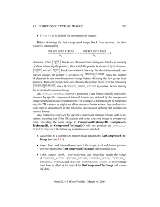
command. If present, a digit indicates the required length (number of values) of the
indicated type. Next, a string of characters making up one of the type descriptors
from table 2.1 indicates the specific size and data type of parameter values. A
final v character, if present, indicates that the command takes a pointer to an array
(a vector) of values rather than a series of individual arguments. Two specific
examples are:
void Uniform4f( int location, float v0, float v1,
float v2, float v3 );
and
void GetFloatv( enum pname, float *data );
In general, a command declaration has the form
rtype Name{ 1234}{ b s i i64 f d ub us ui ui64}{ v}
( [args ,] T arg1, . . ., T argN [, args] );
rtype is the return type of the function. The braces ({}) enclose a series of type
descriptors (see table 2.1), of which one is selected. indicates no type descriptor.
The arguments enclosed in brackets ([args ,] and [, args]) may or may not be
present. The N arguments arg1 through argN have type T, which corresponds to
one of the type descriptors indicated in table 2.1 (if there are no letters, then the
arguments’ type is given explicitly). If the final character is not v, then N is given
by the digit 1, 2, 3, or 4 (if there is no digit, then the number of arguments is fixed).
If the final character is v, then only arg1 is present and it is an array of N values of
the indicated type.
For example,
void Uniform{1234}{if}( int location, T value );
indicates the eight declarations
void Uniform1i( int location, int value );
void Uniform1f( int location, float value );
void Uniform2i( int location, int v0, int v1 );
void Uniform2f( int location, float v0, float v1 );
void Uniform3i( int location, int v0, int v1, int v2 );
void Uniform3f( int location, float v0, float v1,
float v3 );
OpenGL 4.4 (Core Profile) - March 19, 2014](https://image.slidesharecdn.com/glspec44-130724171606-phpapp02/85/OpenGL-Spec-4-4-Core-33-320.jpg)

![2.2. COMMAND SYNTAX 13
GL Type Description
Bit Width
boolean 1 or more Boolean
byte 8 Signed two’s complement binary inte-
ger
ubyte 8 Unsigned binary integer
char 8 Characters making up strings
short 16 Signed two’s complement binary inte-
ger
ushort 16 Unsigned binary integer
int 32 Signed two’s complement binary inte-
ger
uint 32 Unsigned binary integer
fixed 32 Signed two’s complement 16.16
scaled integer
int64 64 Signed two’s complement binary inte-
ger
uint64 64 Unsigned binary integer
sizei 32 Non-negative binary integer size
enum 32 Enumerated binary integer value
intptr ptrbits Signed twos complement binary inte-
ger
sizeiptr ptrbits Non-negative binary integer size
sync ptrbits Sync object handle (see section 4.1)
bitfield 32 Bit field
half 16 Half-precision floating-point value
encoded in an unsigned scalar
float 32 Floating-point value
clampf 32 Floating-point value clamped to [0, 1]
double 64 Floating-point value
clampd 64 Floating-point value clamped to [0, 1]
Table 2.2: GL data types. GL types are not C types. Thus, for example, GL
type int is referred to as GLint outside this document, and is not necessarily
equivalent to the C type int. An implementation must use exactly the number of
bits indicated in the table to represent a GL type.
ptrbits is the number of bits required to represent a pointer type; in other words,
types intptr, sizeiptr, and sync must be large enough to store any CPU ad-
dress. sync is defined as an anonymous struct pointer in the C language bindings
while intptr and sizeiptr are defined as integer types large enough to hold
a pointer.
OpenGL 4.4 (Core Profile) - March 19, 2014](https://image.slidesharecdn.com/glspec44-130724171606-phpapp02/85/OpenGL-Spec-4-4-Core-35-320.jpg)

![2.3. COMMAND EXECUTION 15
buffer clear value. In these cases, the query command converts the floating-
point value to an integer according to the INT entry of table 18.2; a value
not in [−1, 1] converts to an undefined value.
• If a command returning floating-point data is called, such as GetFloatv or
GetDoublev, a boolean value of TRUE or FALSE is interpreted as 1.0 or
0.0, respectively. An integer value is coerced to floating-point. Single- and
double-precision floating-point values are converted as necessary.
If a value is so large in magnitude that it cannot be represented by the returned
data type, then the nearest value representable using the requested type is returned.
When querying bitmasks (such as SAMPLE_MASK_VALUE or STENCIL_-
WRITEMASK) with GetIntegerv, the mask value is treated as a signed integer, so
that mask values with the high bit set will not be clamped when returned as signed
integers.
Unless otherwise indicated, multi-valued state variables return their multiple
values in the same order as they are given as arguments to the commands that set
them. For instance, the two DepthRange parameters are returned in the order n
followed by f.
2.3 Command Execution
Most of the Specification discusses the behavior of a single context bound to a
single CPU thread. It is also possible for multiple contexts to share GL objects
and for each such context to be bound to a different thread. This section introduces
concepts related to GL command execution including error reporting, command
queue flushing, and synchronization between command streams. Using these tools
can increase performance and utilization of the GPU by separating loosely related
tasks into different contexts.
Methods to create, manage, and destroy CPU threads are defined by the host
CPU operating system and are not described in the Specification. Binding of GL
contexts to CPU threads is controlled through a window system binding layer such
as those described in section 1.3.5.
2.3.1 Errors
The GL detects only a subset of those conditions that could be considered errors.
This is because in many cases error checking would adversely impact the perfor-
mance of an error-free program.
The command
OpenGL 4.4 (Core Profile) - March 19, 2014](https://image.slidesharecdn.com/glspec44-130724171606-phpapp02/85/OpenGL-Spec-4-4-Core-37-320.jpg)


![2.3. COMMAND EXECUTION 22
2.3.3.5 Fixed-Point Computation
Vertex attributes may be specified using a 32-bit two’s-complement signed repre-
sentation with 16 bits to the right of the binary point (fraction bits).
2.3.3.6 General Requirements
Some calculations require division. In such cases (including implied divisions re-
quired by vector normalizations), a division by zero produces an unspecified result
but must not lead to GL interruption or termination.
2.3.4 Fixed-Point Data Conversions
When generic vertex attributes and pixel color or depth components are repre-
sented as integers, they are often (but not always) considered to be normalized.
Normalized integer values are treated specially when being converted to and from
floating-point values, and are usually referred to as normalized fixed-point. Such
values are always either signed or unsigned.
In the remainder of this section, b denotes the bit width of the fixed-point inte-
ger representation. When the integer is one of the types defined in table 2.2, b is
the required bit width of that type. When the integer is a texture or renderbuffer
color or depth component (see section 8.5), b is the number of bits allocated to that
component in the internal format of the texture or renderbuffer. When the integer is
a framebuffer color or depth component (see section 9), b is the number of bits allo-
cated to that component in the framebuffer. For framebuffer and renderbuffer alpha
components, b must be at least 2 if the buffer does not contain an alpha component,
or if there is only one bit of alpha in the buffer.
The signed and unsigned fixed-point representations are assumed to be b-bit
binary twos-complement integers and binary unsigned integers, respectively.
2.3.4.1 Conversion from Normalized Fixed-Point to Floating-Point
Unsigned normalized fixed-point integers represent numbers in the range [0, 1].
The conversion from an unsigned normalized fixed-point value c to the correspond-
ing floating-point value f is defined as
f =
c
2b − 1
. (2.1)
Signed normalized fixed-point integers represent numbers in the range [−1, 1].
The conversion from a signed normalized fixed-point value c to the corresponding
OpenGL 4.4 (Core Profile) - March 19, 2014](https://image.slidesharecdn.com/glspec44-130724171606-phpapp02/85/OpenGL-Spec-4-4-Core-44-320.jpg)
![2.3. COMMAND EXECUTION 23
floating-point value f is performed using
f = max
c
2b−1 − 1
, −1.0 . (2.2)
Only the range [−2b−1 + 1, 2b−1 − 1] is used to represent signed fixed-point
values in the range [−1, 1]. For example, if b = 8, then the integer value −127 cor-
responds to −1.0 and the value 127 corresponds to 1.0. Note that while zero can be
exactly expressed in this representation, one value (−128 in the example) is outside
the representable range, and must be clamped before use. This equation is used ev-
erywhere that signed normalized fixed-point values are converted to floating-point,
including for all signed normalized fixed-point parameters in GL commands, such
as vertex attribute values3, as well as for specifying texture or framebuffer values
using signed normalized fixed-point.
2.3.4.2 Conversion from Floating-Point to Normalized Fixed-Point
The conversion from a floating-point value f to the corresponding unsigned nor-
malized fixed-point value c is defined by first clamping f to the range [0, 1], then
computing
f = f × (2b
− 1). (2.3)
f is then cast to an unsigned binary integer value with exactly b bits.
The conversion from a floating-point value f to the corresponding signed nor-
malized fixed-point value c is performed by clamping f to the range [−1, 1], then
computing
f = f × (2b−1
− 1). (2.4)
After conversion, f is then cast to a signed two’s-complement binary integer
value with exactly b bits.
This equation is used everywhere that floating-point values are converted to
signed normalized fixed-point, including when querying floating-point state (see
section 2.2.2) and returning integers4, as well as for specifying signed normalized
texture or framebuffer values using floating-point.
3
This is a behavior change in OpenGL 4.2. In previous versions, a different conversion for signed
normalized values was used in which −128 mapped to −1.0, 127 mapped to 1.0, and 0.0 was not
exactly representable.
4
This is a behavior change in OpenGL 4.2. In previous versions, a different conversion for signed
normalized values was used in which −1.0 mapped to −128, 1.0 mapped to 127, and 0.0 was not
exactly representable.
OpenGL 4.4 (Core Profile) - March 19, 2014](https://image.slidesharecdn.com/glspec44-130724171606-phpapp02/85/OpenGL-Spec-4-4-Core-45-320.jpg)


![6.1. CREATING AND BINDING BUFFER OBJECTS 58
BindBuffersBase is equivalent to:
for (i = 0; i < count; i++) {
if (buffers == NULL) {
BindBufferBase(target, first + i, 0);
} else {
BindBufferBase(target, first + i, buffers[i]);
}
}
except that the single general buffer binding corresponding to target is unmodified,
and that buffers will not be created if they do not exist.
BindBuffersRange is equivalent to:
for (i = 0; i < count; i++) {
if (buffers == NULL) {
BindBufferRange(target, first + i, 0, 0, 0);
} else {
BindBufferRange(target, first + i, buffers[i],
offsets[i], sizes[i]);
}
}
except that the single general buffer binding corresponding to target is unmodified,
and that buffers will not be created if they do not exist.
The values specified in buffers, offsets, and sizes will be checked separately for
each binding point. When values for a specific binding point are invalid, the state
for that binding point will be unchanged and an error will be generated. When
such an error occurs, state for other binding points will still be changed if their
corresponding values are valid.
Errors
An INVALID_ENUM error is generated if target is not one of the targets
listed above.
An INVALID_OPERATION error is generated if first + count is greater
than the number of target-specific indexed binding points, as described in sec-
tion 6.7.1.
An INVALID_OPERATION error is generated if any value in buffers is not
zero or the name of an existing buffer object.
An INVALID_VALUE error is generated by BindBuffersRange if any
OpenGL 4.4 (Core Profile) - March 19, 2014](https://image.slidesharecdn.com/glspec44-130724171606-phpapp02/85/OpenGL-Spec-4-4-Core-80-320.jpg)


![7.3. PROGRAM OBJECTS 92
name string formed by concatenating the name of the array and the string
"[0]".
• For an active variable declared as a structure, a separate entry will be gener-
ated for each active structure member. The name of each entry is formed by
concatenating the name of the structure, the "." character, and the name of
the structure member. If a structure member to enumerate is itself a structure
or array, these enumeration rules are applied recursively.
• For an active variable declared as an array of an aggregate data type (struc-
tures or arrays), a separate entry will be generated for each active array el-
ement, unless noted immediately below. The name of each entry is formed
by concatenating the name of the array, the "[" character, an integer identi-
fying the element number, and the "]" character. These enumeration rules
are applied recursively, treating each enumerated array element as a separate
active variable.
• For an active shader storage block member declared as an array, an entry
will be generated only for the first array element, regardless of its type. Such
block members are referred to as top-level arrays. If the block member is
an aggregate type, the enumeration rules are applied recursively. During this
process, arrays of aggregate data types will enumerate each element sepa-
rately.
• For an active interface block not declared as an array of block instances, a
single entry will be generated, using the block name from the shader source.
• For an active interface block declared as an array of instances, separate en-
tries will be generated for each active instance. The name of the instance
is formed by concatenating the block name, the "[" character, an integer
identifying the instance number, and the "]" character.
• For an active subroutine, a single entry will be generated, using the subrou-
tine name from the shader source.
When an integer array element or block instance number is part of the name
string, it will be specified in decimal form without a "+" or "-" sign or any
extra leading zeroes. Additionally, the name string will not include white space
anywhere in the string.
The order of the active resource list is implementation-dependent for all
interfaces except for TRANSFORM_FEEDBACK_VARYING. If variables in the
OpenGL 4.4 (Core Profile) - March 19, 2014](https://image.slidesharecdn.com/glspec44-130724171606-phpapp02/85/OpenGL-Spec-4-4-Core-114-320.jpg)


![7.3. PROGRAM OBJECTS 95
RESOURCES, MAX_NAME_LENGTH, MAX_NUM_ACTIVE_VARIABLES, or
MAX_NUM_COMPATIBLE_SUBROUTINES.
An INVALID_OPERATION error is generated if pname is MAX_-
NAME_LENGTH and programInterface is ATOMIC_COUNTER_BUFFER or
TRANSFORM_FEEDBACK_BUFFER, since active atomic counter and transform
feedback buffer resources are not assigned name strings.
An INVALID_OPERATION error is generated if pname is MAX_NUM_-
ACTIVE_VARIABLES and programInterface is not ATOMIC_COUNTER_-
BUFFER, SHADER_STORAGE_BLOCK, TRANSFORM_FEEDBACK_BUFFER, or
UNIFORM_BLOCK.
An INVALID_OPERATION error is generated if pname is MAX_-
NUM_COMPATIBLE_SUBROUTINES and programInterface is not
VERTEX_SUBROUTINE_UNIFORM, TESS_CONTROL_SUBROUTINE_-
UNIFORM, TESS_EVALUATION_SUBROUTINE_UNIFORM, GEOMETRY_-
SUBROUTINE_UNIFORM, FRAGMENT_SUBROUTINE_UNIFORM, or
COMPUTE_SUBROUTINE_UNIFORM.
Each entry in the active resource list for an interface is assigned a unique un-
signed integer index in the range zero to N − 1, where N is the number of entries
in the active resource list. The command
uint GetProgramResourceIndex( uint program,
enum programInterface, const char *name );
returns the unsigned integer index assigned to a resource named name in the inter-
face type programInterface of program object program.
If name exactly matches the name string of one of the active resources for
programInterface, the index of the matched resource is returned. Additionally, if
name would exactly match the name string of an active resource if "[0]" were
appended to name, the index of the matched resource is returned. Otherwise, name
is considered not to be the name of an active resource, and INVALID_INDEX is
returned. Note that if an interface enumerates a single active resource list entry for
an array variable (e.g., "a[0]"), a name identifying any array element other than
the first (e.g., "a[1]") is not considered to match.
If programInterface is TRANSFORM_FEEDBACK_VARYING, INVALID_INDEX
is returned when querying the special names gl_NextBuffer, gl_-
SkipComponents1, gl_SkipComponents2, gl_SkipComponents3, and
gl_SkipComponents4, even if those names were provided to TransformFeed-
backVaryings (see section 11.1.2.1).
OpenGL 4.4 (Core Profile) - March 19, 2014](https://image.slidesharecdn.com/glspec44-130724171606-phpapp02/85/OpenGL-Spec-4-4-Core-117-320.jpg)


![7.3. PROGRAM OBJECTS 107
returns the location or the fragment color index, respectively, assigned to the
variable named name in interface programInterface of program object program.
For GetProgramResourceLocation, programInterface must be one of UNIFORM,
PROGRAM_INPUT, PROGRAM_OUTPUT, VERTEX_SUBROUTINE_UNIFORM,
TESS_CONTROL_SUBROUTINE_UNIFORM, TESS_EVALUATION_SUBROUTINE_-
UNIFORM, GEOMETRY_SUBROUTINE_UNIFORM, FRAGMENT_SUBROUTINE_-
UNIFORM, or COMPUTE_SUBROUTINE_UNIFORM. For GetProgramResourceLo-
cationIndex, programInterface must be PROGRAM_OUTPUT. The value -1 will be
returned by either command if an error occurs, if name does not identify an ac-
tive variable on programInterface, or if name identifies an active variable that does
not have a valid location assigned, as described above. The locations returned by
these commands are the same locations returned when querying the LOCATION and
LOCATION_INDEX resource properties.
A string provided to GetProgramResourceLocation or GetProgramRe-
sourceLocationIndex is considered to match an active variable if
• the string exactly matches the name of the active variable;
• if the string identifies the base name of an active array, where the string
would exactly match the name of the variable if the suffix "[0]" were ap-
pended to the string; or
• if the string identifies an active element of the array, where the string ends
with the concatenation of the "[" character, an integer (with no "+" sign,
extra leading zeroes, or whitespace) identifying an array element, and the
"]" character, the integer is less than the number of active elements of the
array variable, and where the string would exactly match the enumerated
name of the array if the decimal integer were replaced with zero.
Any other string is considered not to identify an active variable. If the string
specifies an element of an array variable, GetProgramResourceLocation and
GetProgramResourceLocationIndex return the location or fragment color index
assigned to that element. If it specifies the base name of an array, it identifies the
resources associated with the first element of the array.
Errors
An INVALID_VALUE error is generated if program is not the name of ei-
ther a program or shader object.
An INVALID_OPERATION error is generated if program is the name of a
shader object.
OpenGL 4.4 (Core Profile) - March 19, 2014](https://image.slidesharecdn.com/glspec44-130724171606-phpapp02/85/OpenGL-Spec-4-4-Core-129-320.jpg)


![7.4. PROGRAM PIPELINE OBJECTS 112
– the two variables are declared with the same location and
component layout qualifiers and match in type and qualification.
For the purposes of interface matching, variables declared with a location
layout qualifier but without a component layout qualifier are considered to
have declared a component layout qualifier of zero. Variables or block mem-
bers declared as structures are considered to match in type if and only if structure
members match in name, type, qualification, and declaration order. Variables or
block members declared as arrays are considered to match in type only if both
declarations specify the same element type and array size. The rules for determin-
ing if variables or block members match in qualification are found in the OpenGL
Shading Language Specification.
Tessellation control shader per-vertex output variables and blocks and tessella-
tion control, tessellation evaluation, and geometry shader per-vertex input variables
and blocks are required to be declared as arrays, with each element representing
input or output values for a single vertex of a multi-vertex primitive. For the pur-
poses of interface matching, such variables and blocks are treated as though they
were not declared as arrays.
For program objects containing multiple shaders, LinkProgram will check for
mismatches on interfaces between shader stages in the program being linked and
generate a link error if a mismatch is detected. A link error is generated if any
statically referenced input variable or block does not have a matching output. If
either shader redeclares the built-in array gl_ClipDistance[], the array must
have the same size in both shaders.
With separable program objects, interfaces between shader stages may involve
the outputs from one program object and the inputs from a second program object.
For such interfaces, it is not possible to detect mismatches at link time, because the
programs are linked separately. When each such program is linked, all inputs or
outputs interfacing with another program stage are treated as active. The linker will
generate an executable that assumes the presence of a compatible program on the
other side of the interface. If a mismatch between programs occurs, no GL error is
generated, but some or all of the inputs on the interface will be undefined.
At an interface between program objects, the set of inputs and outputs are con-
sidered to match exactly if and only if:
• Every declared input block or variable must have a matching output, as de-
scribed above.
• There are no output blocks or user-defined output variables declared without
a matching input block or variable declaration.
OpenGL 4.4 (Core Profile) - March 19, 2014](https://image.slidesharecdn.com/glspec44-130724171606-phpapp02/85/OpenGL-Spec-4-4-Core-134-320.jpg)


![7.6. UNIFORM VARIABLES 120
block are not assigned a location and may not be modified using the Uniform*
commands. The offsets and strides of all active uniforms belonging to named uni-
form blocks of a program object are invalidated and new ones assigned after each
successful re-link.
To determine the set of active uniform variables used by a program, applica-
tions can query the properties and active resources of the UNIFORM interface of a
program.
Additionally, several dedicated commands are provided to query properties of
active uniforms. The command
int GetUniformLocation( uint program, const
char *name );
is equivalent to
GetProgramResourceLocation(program, UNIFORM, name);
The command
void GetActiveUniformName( uint program,
uint uniformIndex, sizei bufSize, sizei *length,
char *uniformName );
is equivalent to
GetProgramResourceName(program, UNIFORM, uniformIndex,
bufSize, length, uniformName);
The command
void GetUniformIndices( uint program,
sizei uniformCount, const char * const
*uniformNames, uint *uniformIndices );
is equivalent to
for (int i = 0; i < uniformCount; i++) {
uniformIndices[i] = GetProgramResourceIndex(program,
UNIFORM, uniformNames[i];
}
The command
OpenGL 4.4 (Core Profile) - March 19, 2014](https://image.slidesharecdn.com/glspec44-130724171606-phpapp02/85/OpenGL-Spec-4-4-Core-142-320.jpg)
![7.6. UNIFORM VARIABLES 121
void GetActiveUniform( uint program, uint index,
sizei bufSize, sizei *length, int *size, enum *type,
char *name );
is equivalent to
const enum props[] = { ARRAY_SIZE, TYPE };
GetProgramResourceName(program, UNIFORM, index,
bufSize, length, name);
GetProgramResourceiv(program, UNIFORM, index,
1, &props[0], 1, NULL, size);
GetProgramResourceiv(program, UNIFORM, index,
1, &props[1], 1, NULL, (int *)type);
The command
void GetActiveUniformsiv( uint program,
sizei uniformCount, const uint *uniformIndices,
enum pname, int *params );
is equivalent to
GLenum prop;
for (int i = 0; i < uniformCount; i++) {
GetProgramResourceiv(program, UNIFORM, uniformIndices[i],
1, &prop, 1, NULL, ¶ms[i]);
}
where the value of prop is taken from table 7.6, based on the value of pname.
To determine the set of active uniform blocks used by a program, applications
can query the properties and active resources of the UNIFORM_BLOCK interface.
Additionally, several commands are provided to query properties of active uni-
form blocks. The command
uint GetUniformBlockIndex( uint program, const
char *uniformBlockName );
is equivalent to
GetProgramResourceIndex(program, UNIFORM_BLOCK, uniformBlockName);
The command
OpenGL 4.4 (Core Profile) - March 19, 2014](https://image.slidesharecdn.com/glspec44-130724171606-phpapp02/85/OpenGL-Spec-4-4-Core-143-320.jpg)


![7.10. SAMPLERS 140
void UniformSubroutinesuiv( enum shadertype, sizei count,
const uint *indices );
will load all active subroutine uniforms for shader stage shadertype with subrou-
tine indices from indices, storing indices[i] into the uniform at location i. The
indices for any locations between zero and the value of ACTIVE_SUBROUTINE_-
UNIFORM_LOCATIONS minus one which are not used will be ignored.
Errors
An INVALID_ENUM error is generated if shadertype is not one of the val-
ues in table 7.1,
An INVALID_VALUE error is generated if count is negative, is not equal to
the value of ACTIVE_SUBROUTINE_UNIFORM_LOCATIONS for the program
currently in use at shader stage shadertype, or if the uniform at location i
is used and the value in indices[i] is greater than or equal to the value of
ACTIVE_SUBROUTINES for the shader stage.
An INVALID_VALUE error is generated if the value of indices[i] for a used
uniform location specifies an unused subroutine index.
An INVALID_OPERATION error is generated if, for any subroutine index
being loaded to a particular uniform location, the function corresponding to the
subroutine index was not associated (as defined in section 6.1.2 of the OpenGL
Shading Language Specification) with the type of the subroutine variable at
that location.
An INVALID_OPERATION error is generated if no program is active for
the shader stage identified by shadertype.
Each subroutine uniform must have at least one subroutine to assign to the uni-
form. A program will fail to link if any stage has one or more subroutine uniforms
that has no subroutine associated with the subroutine type of the uniform.
When the active program for a shader stage is re-linked or changed by a call
to UseProgram, BindProgramPipeline, or UseProgramStages, subroutine uni-
forms for that stage are reset to arbitrarily chosen default functions with compatible
subroutine types.
7.10 Samplers
Samplers are special uniforms used in the OpenGL Shading Language to identify
the texture object used for each texture lookup. The value of a sampler indicates
the texture image unit being accessed. Setting a sampler’s value to i selects texture
OpenGL 4.4 (Core Profile) - March 19, 2014](https://image.slidesharecdn.com/glspec44-130724171606-phpapp02/85/OpenGL-Spec-4-4-Core-162-320.jpg)


![7.12. SHADER MEMORY ACCESS 143
ship test (see section 17.3.1), the fragment shader may not be executed. Oth-
erwise, if the framebuffer has no multisample buffer (the value of SAMPLE_-
BUFFERS is zero), the fragment shader will be invoked exactly once. If the
fragment shader specifies per-sample shading, the fragment shader will be
run once per covered sample. Otherwise, the number of fragment shader
invocations is undefined, but must be in the range [1, N], where N is the
number of samples covered by the fragment.
• If a fragment shader is invoked to process fragments or samples not covered
by a primitive being rasterized to facilitate the approximation of derivatives
for texture lookups, stores and atomics have no effect.
• The relative order of invocations of the same shader type are undefined. A
store issued by a shader when working on primitive B might complete prior
to a store for primitive A, even if primitive A is specified prior to primitive
B. This applies even to fragment shaders; while fragment shader outputs are
written to the framebuffer in primitive order, stores executed by fragment
shader invocations are not.
• The relative order of invocations of different shader types is largely unde-
fined. However, when executing a shader whose inputs are generated from
a previous programmable stage, the shader invocations from the previous
stage are guaranteed to have executed far enough to generate final values
for all next-stage inputs. That implies shader completion for all stages ex-
cept geometry; geometry shaders are guaranteed only to have executed far
enough to emit all needed vertices.
The above limitations on shader invocation order also make some forms of
synchronization between shader invocations within a single set of primitives unim-
plementable. For example, having one invocation poll memory written by another
invocation assumes that the other invocation has been launched and can complete
its writes. The only case where such a guarantee is made is when the inputs of
one shader invocation are generated from the outputs of a shader invocation in a
previous stage.
Stores issued to different memory locations within a single shader invocation
may not be visible to other invocations in the order they were performed. The built-
in function memoryBarrier may be used to provide stronger ordering of reads
and writes performed by a single invocation. Calling memoryBarrier guarantees
that any memory transactions issued by the shader invocation prior to the call com-
plete prior to the memory transactions issued after the call. Memory barriers may
OpenGL 4.4 (Core Profile) - March 19, 2014](https://image.slidesharecdn.com/glspec44-130724171606-phpapp02/85/OpenGL-Spec-4-4-Core-165-320.jpg)


![7.13. SHADER, PROGRAM, AND PROGRAM PIPELINE QUERIES 154
into source, excluding the null terminator, is returned in length. If length is NULL,
no length is returned. The maximum number of characters that may be written into
source, including the null terminator, is specified by bufSize. The string source is
a concatenation of the strings passed to the GL using ShaderSource. The length
of this concatenation is given by SHADER_SOURCE_LENGTH, which can be queried
with GetShaderiv.
Errors
An INVALID_VALUE error is generated if shader is not the name of either
a program or shader object.
An INVALID_OPERATION error is generated if shader is the name of a
program object.
An INVALID_VALUE error is generated if bufSize is negative.
The command
void GetShaderPrecisionFormat( enum shadertype,
enum precisiontype, int *range, int *precision );
returns the range and precision for different numeric formats supported by the
shader compiler. shadertype must be VERTEX_SHADER or FRAGMENT_SHADER.
precisiontype must be one of LOW_FLOAT, MEDIUM_FLOAT, HIGH_FLOAT, LOW_-
INT, MEDIUM_INT or HIGH_INT. range points to an array of two integers in which
encodings of the format’s numeric range are returned. If min and max are the
smallest and largest values representable in the format, then the values returned are
defined to be
range[0] = log2(|min|)
range[1] = log2(|max|)
precision points to an integer in which the log2 value of the number of bits of
precision of the format is returned. If the smallest representable value greater than
1 is 1 + , then *precision will contain −log2( ) , and every value in the range
[−2range[0]
, 2range[1]
]
can be represented to at least one part in 2∗precision. For example, an IEEE single-
precision floating-point format would return range[0] = 127, range[1] = 127,
and ∗precision = 23, while a 32-bit two’s-complement integer format would re-
turn range[0] = 31, range[1] = 30, and ∗precision = 0.
OpenGL 4.4 (Core Profile) - March 19, 2014](https://image.slidesharecdn.com/glspec44-130724171606-phpapp02/85/OpenGL-Spec-4-4-Core-176-320.jpg)


![8.1. TEXTURE OBJECTS 162
name returned from a previous call to GenTextures, or if such a name has
since been deleted.
The command
void BindTextures( uint first, sizei count, const
uint *textures );
binds count existing texture objects to texture image units numbered first through
first + count − 1. If textures is not NULL, it specifies an array of count values,
each of which must be zero or the name of an existing texture object. When an
entry in textures is the name of an existing texture object, that object is bound to
the target, in the corresponding texture unit, that was specified when the object was
created. When an entry in textures is zero, each of the targets enumerated at the
beginning of this section is reset to its default texture for the corresponding texture
image unit. If textures is NULL, each target of each affected texture image unit from
first to first + count − 1 is reset to its default texture.
BindTextures is equivalent to
for (i = 0; i < count; i++) {
uint texture;
if (textures == NULL) {
texture = 0;
} else {
texture = textures[i];
}
ActiveTexture(TEXTURE0 + first + i);
if (texture != 0) {
enum target = /* target of textures[i] */;
BindTexture(target, textures[i]);
} else {
for (target in all supported targets) {
BindTexture(target, 0);
}
}
}
except that the active texture selector retains its original value upon completion of
the command, and that textures will not be created if they do not exist.
The values specified in textures will be checked separately for each texture
image unit. When a value for a specific texture image unit is invalid, the state for
OpenGL 4.4 (Core Profile) - March 19, 2014](https://image.slidesharecdn.com/glspec44-130724171606-phpapp02/85/OpenGL-Spec-4-4-Core-184-320.jpg)


![8.2. SAMPLER OBJECTS 166
for (i = 0; i < count; i++) {
if (samplers == NULL) {
BindSampler(first + i, 0);
} else {
BindSampler(first + i, samplers[i]);
}
}
The values specified in samplers will be checked separately for each texture
image unit. When a value for a specific texture image unit is invalid, the state for
that texture image unit will be unchanged and an error will be generated. However,
state for other texture image units will still be changed if their corresponding values
are valid.
Errors
An INVALID_OPERATION error is generated if first + count is greater
than the number of texture image units supported by the implementation.
An INVALID_OPERATION error is generated if any value in samplers is
not zero or the name of an existing sampler object (per binding).
The parameters represented by a sampler object are a subset of those described
in section 8.10. Each parameter of a sampler object is set by calling
void SamplerParameter{if}( uint sampler, enum pname,
T param );
void SamplerParameter{if}v( uint sampler, enum pname,
const T *param );
void SamplerParameterI{i ui}v( uint sampler, enum pname,
const T *params );
sampler is the name of a sampler object previously reserved by a call to GenSam-
plers. pname is the name of a parameter to modify and param is the new value of
that parameter. pname must be one of the sampler state names in table 23.18.
Texture state listed in tables 23.16- 23.17 but not listed here and in the sampler
state in table 23.18 is not part of the sampler state, and remains in the texture object.
Data conversions are performed as specified in section 2.2.1, with these ex-
ceptions:
• If the values for TEXTURE_BORDER_COLOR are specified with SamplerPa-
rameterIiv or SamplerParameterIuiv, they are unmodified and stored with
OpenGL 4.4 (Core Profile) - March 19, 2014](https://image.slidesharecdn.com/glspec44-130724171606-phpapp02/85/OpenGL-Spec-4-4-Core-188-320.jpg)


![8.4. PIXEL RECTANGLES 174
Format Name Element Meaning and Order Target Buffer
STENCIL_INDEX Stencil Index Stencil
DEPTH_COMPONENT Depth Depth
DEPTH_STENCIL Depth and Stencil Index Depth and Stencil
RED R Color
GREEN G Color
BLUE B Color
RG R, G Color
RGB R, G, B Color
RGBA R, G, B, A Color
BGR B, G, R Color
BGRA B, G, R, A Color
RED_INTEGER iR Color
GREEN_INTEGER iG Color
BLUE_INTEGER iB Color
RG_INTEGER iR, iG Color
RGB_INTEGER iR, iG, iB Color
RGBA_INTEGER iR, iG, iB, iA Color
BGR_INTEGER iB, iG, iR Color
BGRA_INTEGER iB, iG, iR, iA Color
Table 8.3: Pixel data formats. The second column gives a description of and the
number and order of elements in a group. Unless specified as an index, formats
yield components. Components are floating-point unless prefixed with the letter
’i’, which indicates they are integer.
Element Size Default Bit Ordering Modified Bit Ordering
8 bit [7..0] [7..0]
16 bit [15..0] [7..0][15..8]
32 bit [31..0] [7..0][15..8][23..16][31..24]
Table 8.4: Bit ordering modification of elements when UNPACK_SWAP_BYTES is
enabled. These reorderings are defined only when GL data type ubyte has 8 bits,
and then only for GL data types with 8, 16, or 32 bits. Bit 0 is the least significant.
OpenGL 4.4 (Core Profile) - March 19, 2014](https://image.slidesharecdn.com/glspec44-130724171606-phpapp02/85/OpenGL-Spec-4-4-Core-196-320.jpg)


![8.5. TEXTURE IMAGE SPECIFICATION 184
The groups in memory are treated as being arranged in a sequence of adjacent
rectangles. Each rectangle is a two-dimensional image, whose size and organiza-
tion are specified by the width and height parameters to TexImage3D. The val-
ues of UNPACK_ROW_LENGTH and UNPACK_ALIGNMENT control the row-to-row
spacing in these images as described in section 8.4.4. If the value of the integer
parameter UNPACK_IMAGE_HEIGHT is not positive, then the number of rows in
each two-dimensional image is height; otherwise the number of rows is UNPACK_-
IMAGE_HEIGHT. Each two-dimensional image comprises an integral number of
rows, and is exactly adjacent to its neighbor images.
The mechanism for selecting a sub-volume of a three-dimensional image relies
on the integer parameter UNPACK_SKIP_IMAGES. If UNPACK_SKIP_IMAGES is
positive, the pointer is advanced by UNPACK_SKIP_IMAGES times the number of
elements in one two-dimensional image before obtaining the first group from mem-
ory. Then depth two-dimensional images are processed, each having a subimage
extracted as described in section 8.4.4.
The selected groups are transferred to the GL as described in section 8.4.4
and then clamped to the representable range of the internal format. If the inter-
nalformat of the texture is signed or unsigned integer, components are clamped
to [−2n−1, 2n−1 − 1] or [0, 2n − 1], respectively, where n is the number of bits
per component. For color component groups, if the internalformat of the texture
is signed or unsigned normalized fixed-point, components are clamped to [−1, 1]
or [0, 1], respectively. For depth component groups, the depth value is clamped
to [0, 1]. Otherwise, values are not modified. Stencil index values are masked by
2n − 1, where n is the number of stencil bits in the internal format resolution (see
below). If the base internal format is DEPTH_STENCIL and format is not DEPTH_-
STENCIL, then the values of the stencil index texture components are undefined.
Components are then selected from the resulting R, G, B, A, depth, or stencil
values to obtain a texture with the base internal format specified by (or derived
from) internalformat. Table 8.11 summarizes the mapping of R, G, B, A, depth,
or stencil values to texture components, as a function of the base internal format
of the texture image. internalformat may be specified as one of the internal format
symbolic constants listed in table 8.11, as one of the sized internal format symbolic
constants listed in tables 8.12- 8.13, as one of the generic compressed internal
format symbolic constants listed in table 8.14, or as one of the specific compressed
internal format symbolic constants (if listed in table 8.14).
An INVALID_VALUE error is generated if internalformat is not one of the
above values.
Textures with a base internal format of DEPTH_COMPONENT, DEPTH_-
STENCIL, or STENCIL_INDEX are supported by texture image specification
commands only if target is TEXTURE_1D, TEXTURE_2D, TEXTURE_2D_-
OpenGL 4.4 (Core Profile) - March 19, 2014](https://image.slidesharecdn.com/glspec44-130724171606-phpapp02/85/OpenGL-Spec-4-4-Core-206-320.jpg)


![8.6. ALTERNATE TEXTURE IMAGE SPECIFICATION COMMANDS 202
Counting from zero, the nth pixel group is assigned to the texel with internal integer
coordinates [i, j, k], where
i = x + (n mod w)
j = y + (
n
w
mod h)
k = z + (
n
width ∗ height
mod d
Arguments xoffset and yoffset of TexSubImage2D and CopyTexSubImage2D
specify the lower left texel coordinates of a width-wide by height-high rectangular
subregion of the texel array. Negative values of xoffset and yoffset correspond to
the coordinates of border texels, addressed as in figure 8.3. Taking ws, hs, and bs
to be the specified width, height, and border width of the texel array, and taking x,
y, w, and h to be the xoffset, yoffset, width, and height argument values, any of the
following relationships generates an INVALID_VALUE error:
x < −bs
x + w > ws − bs
y < −bs
y + h > hs − bs
Counting from zero, the nth pixel group is assigned to the texel with internal integer
coordinates [i, j], where
i = x + (n mod w)
j = y + (
n
w
mod h)
The xoffset argument of TexSubImage1D and CopyTexSubImage1D speci-
fies the left texel coordinate of a width-wide subregion of the texel array. Negative
values of xoffset correspond to the coordinates of border texels. Taking ws and bs
to be the specified width and border width of the texel array, and x and w to be the
xoffset and width argument values, either of the following relationships generates
an INVALID_VALUE error:
x < −bs
x + w > ws − bs
Counting from zero, the nth pixel group is assigned to the texel with internal integer
coordinates [i], where
OpenGL 4.4 (Core Profile) - March 19, 2014](https://image.slidesharecdn.com/glspec44-130724171606-phpapp02/85/OpenGL-Spec-4-4-Core-224-320.jpg)


![8.14. TEXTURE MINIFICATION 227
The required state is one bit indicating whether seamless cube map filtering is
enabled or disabled. Initially, it is disabled.
8.14 Texture Minification
Applying a texture to a primitive implies a mapping from texture image space to
framebuffer image space. In general, this mapping involves a reconstruction of
the sampled texture image, followed by a homogeneous warping implied by the
mapping to framebuffer space, then a filtering, followed finally by a resampling
of the filtered, warped, reconstructed image before applying it to a fragment. In
the GL this mapping is approximated by one of two simple filtering schemes. One
of these schemes is selected based on whether the mapping from texture space to
framebuffer space is deemed to magnify or minify the texture image.
8.14.1 Scale Factor and Level of Detail
The choice is governed by a scale factor ρ(x, y) and the level-of-detail parameter
λ(x, y), defined as
λbase(x, y) = log2[ρ(x, y)] (8.4)
λ (x, y) = λbase(x, y) + clamp(biastexobj + biasshader) (8.5)
λ =
lodmax, λ > lodmax
λ , lodmin ≤ λ ≤ lodmax
lodmin, λ < lodmin
undefined, lodmin > lodmax
(8.6)
biastexobj is the value of TEXTURE_LOD_BIAS for the bound texture object (as
described in section 8.10). biasshader is the value of the optional bias parameter
in the texture lookup functions available to fragment shaders. If the texture access
is performed in a fragment shader without a provided bias, or outside a fragment
shader, then biasshader is zero. The sum of these values is clamped to the range
[−biasmax, biasmax] where biasmax is the value of the implementation defined
constant MAX_TEXTURE_LOD_BIAS.
Different implementations have chosen to perform clamping on intermediate
and final terms in computing λ differently. Care should be taken that intermediate
terms do not exceed the implementation-dependent range as different results may
otherwise occur.
OpenGL 4.4 (Core Profile) - March 19, 2014](https://image.slidesharecdn.com/glspec44-130724171606-phpapp02/85/OpenGL-Spec-4-4-Core-249-320.jpg)


![8.14. TEXTURE MINIFICATION 231
i < −bs i ≥ wt + bs
j < −bs j ≥ ht + bs
k < −bs k ≥ dt + bs
then the border values defined by TEXTURE_BORDER_COLOR are used in place
of the non-existent texel. If the texture contains color components, the values of
TEXTURE_BORDER_COLOR are interpreted as an RGBA color to match the texture’s
internal format in a manner consistent with table 8.11. The internal data type of the
border values must be consistent with the type returned by the texture as described
in chapter 8, or the result is undefined. Border values are clamped before they are
used, according to the format in which texture components are stored. For signed
and unsigned normalized fixed-point formats, border values are clamped to [−1, 1]
and [0, 1], respectively. For floating-point and integer formats, border values are
clamped to the representable range of the format. For compressed formats, border
values are clamped as signed normalized (“snorm”), unsigned normalized (“un-
orm”), or floating-point as described in table 8.14 for each format. If the texture
contains depth components, the first component of TEXTURE_BORDER_COLOR is
interpreted as a depth value.
When the value of TEXTURE_MIN_FILTER is LINEAR, a 2 × 2 × 2 cube of
texels in the image array of level levelbase is selected. Let
i0 = wrap( u − 0.5 )
j0 = wrap( v − 0.5 )
k0 = wrap( w − 0.5 )
i1 = wrap( u − 0.5 + 1)
j1 = wrap( v − 0.5 + 1)
k1 = wrap( w − 0.5 + 1)
α = frac(u − 0.5)
β = frac(v − 0.5)
γ = frac(w − 0.5)
where frac(x) denotes the fractional part of x.
OpenGL 4.4 (Core Profile) - March 19, 2014](https://image.slidesharecdn.com/glspec44-130724171606-phpapp02/85/OpenGL-Spec-4-4-Core-253-320.jpg)


![8.14. TEXTURE MINIFICATION 235
max(1,
wt
wd
) × max(1,
ht
hd
) × max(1,
dt
dd
)
where
wd = 2i
hd =
1, for 1D and 1D array textures
2i, otherwise
dd =
2i, for 3D textures
1, otherwise
until the last array is reached with dimension 1 × 1 × 1.
Each array in a mipmap is defined using TexImage3D, TexImage2D, Copy-
TexImage2D, TexImage1D, or CopyTexImage1D or by functions that are de-
fined in terms of these functions. The array being set is indicated with the level-
of-detail argument level. Level-of-detail numbers proceed from levelbase for the
original texel array through the maximum level p, with each unit increase in-
dicating an array of half the dimensions of the previous one (rounded down to
the next integer if fractional) as already described. For immutable-format tex-
tures, levelbase is clamped to the range [0, levelimmut − 1], levelmax is then
clamped to the range [levelbase, levelimmut −1], and p is one less than levelimmut,
where levelimmut is the levels parameter passed to TexStorage* for the texture
object (the value of TEXTURE_IMMUTABLE_LEVELS; see section 8.19). Other-
wise p = log2(maxsize) + levelbase, and all arrays from levelbase through
q = min{p, levelmax} must be defined, as discussed in section 8.17.
by TexParameter* if either value is negative.
The mipmap is used in conjunction with the level of detail to approximate the
application of an appropriately filtered texture to a fragment. Let c be the value
of λ at which the transition from minification to magnification occurs (since this
discussion pertains to minification, we are concerned only with values of λ where
λ > c).
For mipmap filters NEAREST_MIPMAP_NEAREST and LINEAR_MIPMAP_-
NEAREST, the dth mipmap array is selected, where
d =
levelbase, λ ≤ 1
2
levelbase + λ + 1
2 − 1, λ > 1
2, levelbase + λ ≤ q + 1
2
4
q, λ > 1
2, levelbase + λ > q + 1
2
(8.11)
OpenGL 4.4 (Core Profile) - March 19, 2014](https://image.slidesharecdn.com/glspec44-130724171606-phpapp02/85/OpenGL-Spec-4-4-Core-257-320.jpg)
![8.14. TEXTURE MINIFICATION 236
The rules for NEAREST or LINEAR filtering are then applied to the selected
array. Specifically, the coordinate (u, v, w) is computed as in equation 8.7, with
ws, hs, and ds equal to the width, height, and depth of the image array whose level
is d.
For mipmap filters NEAREST_MIPMAP_LINEAR and LINEAR_MIPMAP_-
LINEAR, the level d1 and d2 mipmap arrays are selected, where
d1 =
q, levelbase + λ ≥ q
levelbase + λ , otherwise
(8.12)
d2 =
q, levelbase + λ ≥ q
d1 + 1, otherwise
(8.13)
The rules for NEAREST or LINEAR filtering are then applied to each of the
selected arrays, yielding two corresponding texture values τ1 and τ2. Specifically,
for level d1, the coordinate (u, v, w) is computed as in equation 8.7, with ws, hs,
and ds equal to the width, height, and depth of the image array whose level is d1.
For level d2 the coordinate (u , v , w ) is computed as in equation 8.7, with ws, hs,
and ds equal to the width, height, and depth of the image array whose level is d2.
The final texture value is then found as
τ = [1 − frac(λ)]τ1 + frac(λ)τ2.
8.14.4 Manual Mipmap Generation
Mipmaps can be generated manually with the command
void GenerateMipmap( enum target );
where target is one of TEXTURE_1D, TEXTURE_2D, TEXTURE_3D, TEXTURE_-
1D_ARRAY, TEXTURE_2D_ARRAY, TEXTURE_CUBE_MAP, or TEXTURE_CUBE_-
MAP_ARRAY.
Mipmap generation affects the texture image attached to target.
If target is TEXTURE_CUBE_MAP or TEXTURE_CUBE_MAP_ARRAY, the texture
bound to target must be cube complete or cube array complete respectively, as
defined in section 8.17.
Mipmap generation replaces texel array levels levelbase + 1 through q with
arrays derived from the levelbase array, regardless of their previous contents. All
4
Implementations may instead use the nearly equivalent computation d = levelbase + λ + 1
2
in this case.
OpenGL 4.4 (Core Profile) - March 19, 2014](https://image.slidesharecdn.com/glspec44-130724171606-phpapp02/85/OpenGL-Spec-4-4-Core-258-320.jpg)


![8.23. TEXTURE COMPARISON MODES 255
8.23 Texture Comparison Modes
Texture values can also be computed according to a specified comparison function.
Texture parameter TEXTURE_COMPARE_MODE specifies the comparison operands,
and parameter TEXTURE_COMPARE_FUNC specifies the comparison function.
8.23.1 Depth Texture Comparison Mode
If the currently bound texture’s base internal format is DEPTH_COMPONENT or
DEPTH_STENCIL, then TEXTURE_COMPARE_MODE and TEXTURE_COMPARE_-
FUNC control the output of the texture unit as described below. Otherwise, the
texture unit operates in the normal manner and texture comparison is bypassed.
Let Dt be the depth texture value and St be the stencil index component. If
there is no stencil component, the value of St is undefined. Let Dref be the ref-
erence value, provided by the shader’s texture lookup function. If the texture’s
internal format indicates a fixed-point depth texture, then Dt and Dref are clamped
to the range [0, 1]; otherwise no clamping is performed.
Then the effective texture value is computed as follows:
• If the base internal format is STENCIL_INDEX, then r = St.
• If the base internal format is DEPTH_STENCIL and the value of DEPTH_-
STENCIL_TEXTURE_MODE is STENCIL_INDEX, then r = St
• Otherwise, if the value of TEXTURE_COMPARE_MODE is NONE, then r = Dt
• Otherwise, if the value of TEXTURE_COMPARE_MODE is COMPARE_REF_-
TO_TEXTURE, then r depends on the texture comparison function as shown
in table 8.22
The resulting r is assigned to Rt.
If the value of TEXTURE_MAG_FILTER is not NEAREST, or the value of
TEXTURE_MIN_FILTER is not NEAREST or NEAREST_MIPMAP_NEAREST, then r
may be computed by comparing more than one depth texture value to the texture
reference value. The details of this are implementation-dependent, but r should
be a value in the range [0, 1] which is proportional to the number of comparison
passes or failures.
8.24 sRGB Texture Color Conversion
If the currently bound texture’s internal format is one of the sRGB formats in ta-
ble 8.23, the red, green, and blue components are converted from an sRGB color
OpenGL 4.4 (Core Profile) - March 19, 2014](https://image.slidesharecdn.com/glspec44-130724171606-phpapp02/85/OpenGL-Spec-4-4-Core-277-320.jpg)
![8.25. SHARED EXPONENT TEXTURE COLOR CONVERSION 256
Texture Comparison Function Computed result r
LEQUAL r =
1.0, Dref ≤ Dt
0.0, Dref > Dt
GEQUAL r =
1.0, Dref ≥ Dt
0.0, Dref < Dt
LESS r =
1.0, Dref < Dt
0.0, Dref ≥ Dt
GREATER r =
1.0, Dref > Dt
0.0, Dref ≤ Dt
EQUAL r =
1.0, Dref = Dt
0.0, Dref = Dt
NOTEQUAL r =
1.0, Dref = Dt
0.0, Dref = Dt
ALWAYS r = 1.0
NEVER r = 0.0
Table 8.22: Depth texture comparison functions.
space to a linear color space as part of filtering described in sections 8.14 and 8.15.
Any alpha component is left unchanged. Ideally, implementations should perform
this color conversion on each sample prior to filtering but implementations are al-
lowed to perform this conversion after filtering (though this post-filtering approach
is inferior to converting from sRGB prior to filtering).
The conversion from an sRGB encoded component cs to a linear component cl
is as follows.
cl =
cs
12.92, cs ≤ 0.04045
cs+0.055
1.055
2.4
, cs > 0.04045
(8.14)
Assume cs is the sRGB component in the range [0, 1].
8.25 Shared Exponent Texture Color Conversion
If the currently bound texture’s internal format is RGB9_E5, the red, green, blue,
and shared bits are converted to color components (prior to filtering) using shared
exponent decoding. The component reds, greens, blues, and exps values (see
OpenGL 4.4 (Core Profile) - March 19, 2014](https://image.slidesharecdn.com/glspec44-130724171606-phpapp02/85/OpenGL-Spec-4-4-Core-278-320.jpg)


![8.26. TEXTURE IMAGE LOADS AND STORES 259
Errors
An INVALID_VALUE error is generated if unit is greater than or equal to
the value of MAX_IMAGE_UNITS, if level or layer is negative, or if texture is
not the name of an existing texture object.
An INVALID_VALUE error is generated if format is not one of the formats
listed in table 8.25.
The command
void BindImageTextures( uint first, sizei count, const
uint *textures );
binds count existing texture objects to image units numbered first through first +
count − 1. If textures is not NULL, it specifies an array of count values, each of
which must be zero or the name of an existing texture object. If textures is NULL,
each affected image unit from first through first + count − 1 will be reset to have
no bound texture object.
When binding a non-zero texture object to an image unit, the image unit level,
layered, layer, and access parameters are set to zero, TRUE, zero, and READ_-
WRITE, respectively. The image unit format parameter is taken from the internal
format of the texture image at level zero of the texture object identified by tex-
tures. For cube map textures, the internal format of the TEXTURE_CUBE_MAP_-
POSITIVE_X image of level zero is used. For multisample, multisample array,
buffer, and rectangle textures, the internal format of the single texture level is used.
When unbinding a texture object from an image unit, the image unit parameters
level, layered, layer, and format will be reset to their default values of zero, FALSE,
0, and R8, respectively.
BindImageTextures is equivalent to
for (i = 0; i < count; i++) {
if (textures == NULL || textures[i] = 0) {
BindImageTexture(first + i, 0, 0, FALSE, 0,
READ_ONLY, R8);
} else {
BindImageTexture(first + i, textures[i], 0, TRUE, 0,
READ_WRITE, lookupInternalFormat(textures[i]));
}
}
where lookupInternalFormat returns the internal format of the specified
texture object.
OpenGL 4.4 (Core Profile) - March 19, 2014](https://image.slidesharecdn.com/glspec44-130724171606-phpapp02/85/OpenGL-Spec-4-4-Core-281-320.jpg)


![9.4. FRAMEBUFFER COMPLETENESS 292
• If image is a non-immutable format texture, the selected level number is in
the range [levelbase, q], where levelbase and q are as defined in section 8.14.3.
• If image is a non-immutable format texture and the selected level is not
levelbase, the texture must be mipmap complete; if image is part of a cube-
map texture, the texture must also be mipmap cube complete.
• If attachment is COLOR_ATTACHMENTi, then image must have a color-
renderable internal format.
• If attachment is DEPTH_ATTACHMENT, then image must have a depth-
renderable internal format.
• If attachment is STENCIL_ATTACHMENT, then image must have a stencil-
renderable internal format.
9.4.2 Whole Framebuffer Completeness
Each rule below is followed by an error token enclosed in { brackets }. The mean-
ing of these errors is explained below and under “Effects of Framebuffer Com-
pleteness on Framebuffer Operations” in section 9.4.4.
The framebuffer object target is said to be framebuffer complete if all the fol-
lowing conditions are true:
• if target is the default framebuffer, the default framebuffer exists.
{ FRAMEBUFFER_UNDEFINED }
• All framebuffer attachment points are framebuffer attachment complete.
{ FRAMEBUFFER_INCOMPLETE_ATTACHMENT }
• There is at least one image attached to the framebuffer, or the value of
the framebuffer’s FRAMEBUFFER_DEFAULT_WIDTH and FRAMEBUFFER_-
DEFAULT_HEIGHT parameters are both non-zero.
{ FRAMEBUFFER_INCOMPLETE_MISSING_ATTACHMENT }
• The combination of internal formats of the attached images does not violate
an implementation-dependent set of restrictions.
{ FRAMEBUFFER_UNSUPPORTED }
OpenGL 4.4 (Core Profile) - March 19, 2014](https://image.slidesharecdn.com/glspec44-130724171606-phpapp02/85/OpenGL-Spec-4-4-Core-314-320.jpg)


![10.2. CURRENT VERTEX ATTRIBUTE VALUES 309
Errors
An INVALID_ENUM error is generated if pname is not PATCH_VERTICES.
An INVALID_VALUE error is generated if value is less than or equal to
zero, or greater than the implementation-dependent maximum patch size (the
value of MAX_PATCH_VERTICES). The patch size is initially three vertices.
If the number of vertices in a patch is given by v, the vi + 1st through vi + vth
vertices (in that order) determine a patch for each i = 0, 1, . . . n − 1, where there
are vn + k vertices. k is in the range [0, v − 1]; if k is not zero, the final k vertices
are ignored.
10.1.16 General Considerations For Polygon Primitives
Depending on the current state of the GL, a polygon primitive generated from a
drawing command with mode TRIANGLE_FAN, TRIANGLE_STRIP, TRIANGLES,
TRIANGLES_ADJACENCY, or TRIANGLE_STRIP_ADJACENCY may be rendered in
one of several ways, such as outlining its border or filling its interior. The or-
der of vertices in such a primitive is significant in polygon rasterization (see sec-
tion 14.6.1) and fragment shading (see section 15.2.2).
10.1.17
This subsection is only defined in the compatibility profile.
10.2 Current Vertex Attribute Values
The commands in this section are used to specify current attribute values. These
values are used by drawing commands to define the attributes transferred for a
vertex when a vertex array defining a required attribute is not enabled, as described
in section 10.3.
10.2.1 Current Generic Attributes
Vertex shaders (see section 11.1) access an array of 4-component generic vertex
attributes. The first slot of this array is numbered zero, and the size of the array is
specified by the value of the implementation-dependent constant MAX_VERTEX_-
ATTRIBS.
OpenGL 4.4 (Core Profile) - March 19, 2014](https://image.slidesharecdn.com/glspec44-130724171606-phpapp02/85/OpenGL-Spec-4-4-Core-331-320.jpg)
![10.2. CURRENT VERTEX ATTRIBUTE VALUES 310
The current values of a generic shader attribute declared as a floating-point
scalar, vector, or matrix may be changed at any time by issuing one of the com-
mands
void VertexAttrib{1234}{sfd}( uint index, T values );
void VertexAttrib{123}{sfd}v( uint index, const
T *values );
void VertexAttrib4{bsifd ub us ui}v( uint index, const
T *values );
void VertexAttrib4Nub( uint index, ubyte x, ubyte y,
ubyte z, ubyte w );
void VertexAttrib4N{bsi ub us ui}v( uint index, const
T *values );
void VertexAttribI{1234}{i ui}( uint index, T values );
void VertexAttribI{1234}{i ui}v( uint index, const
T *values );
void VertexAttribI4{b s ub us}v( uint index, const
T *values );
void VertexAttribL{1234}d( uint index, const T values );
void VertexAttribL{1234}dv( uint index, const T *values );
void VertexAttribP{1234}ui(uint index,enum
type,boolean normalized,uint value);
void VertexAttribP{1234}uiv(uint index,enum
type,boolean normalized,const uint *value);
The VertexAttrib4N* commands specify fixed-point values that are converted
to a normalized [0, 1] or [−1, 1] range as described in equations 2.1 and 2.2, re-
spectively.
The VertexAttribI* commands specify signed or unsigned fixed-point values
that are stored as signed or unsigned integers, respectively. Such values are referred
to as pure integers.
The VertexAttribL* commands specify double-precision values that will be
stored as double-precision values.
The VertexAttribP* commands specify up to four attribute component values
packed into a single natural type type as described in section 10.3.7. type must be
INT_2_10_10_10_REV, UNSIGNED_INT_2_10_10_10_REV, or UNSIGNED_-
INT_10F_11F_11F_REV, specifying signed, unsigned, or unsigned floating-point
data, respectively. The first one (x), two (x, y), three (x, y, z), or four (x, y, z, w)
components of the packed data are consumed by VertexAttribP1ui, VertexAt-
tribP2ui, VertexAttribP3ui, and VertexAttribP4ui, respectively. If normalized
OpenGL 4.4 (Core Profile) - March 19, 2014](https://image.slidesharecdn.com/glspec44-130724171606-phpapp02/85/OpenGL-Spec-4-4-Core-332-320.jpg)
![10.2. CURRENT VERTEX ATTRIBUTE VALUES 311
is TRUE, signed or unsigned components are converted to floating-point by normal-
izing to [−1, 1] or [0, 1] respectively. If normalized is FALSE, signed and unsigned
components are directly cast to floating-point. For floating-point formats, normal-
ized is ignored. The number of components specified must be no greater than the
number of components in the packed type. For VertexAttribP*uiv, value contains
the address of a single uint containing the packed attribute components.
All other VertexAttrib* commands specify values that are converted directly
to the internal floating-point representation.
The resulting value(s) are loaded into the generic attribute at slot index, whose
components are named x, y, z, and w. The VertexAttrib1* family of commands
sets the x coordinate to the provided single argument while setting y and z to 0 and
w to 1. Similarly, VertexAttrib2* commands set x and y to the specified values,
z to 0 and w to 1; VertexAttrib3* commands set x, y, and z, with w set to 1, and
VertexAttrib4* commands set all four coordinates.
The VertexAttrib* entry points may also be used to load shader attributes de-
clared as a floating-point matrix. Each column of a matrix takes up one generic
4-component attribute slot out of the MAX_VERTEX_ATTRIBS available slots. Ma-
trices are loaded into these slots in column major order. Matrix columns are loaded
in increasing slot numbers.
When values for a vertex shader attribute variable are sourced from a current
generic attribute value, the attribute must be specified by a command compatible
with the data type of the variable. The values loaded into a shader attribute variable
bound to generic attribute index are undefined if the current value for attribute index
was not specified by
• VertexAttrib[1234]* or VertexAttribP*, for single-precision floating-point
scalar, vector, and matrix types
• VertexAttribI[1234]i or VertexAttribI[1234]iv, for signed integer scalar
and vector types
• VertexAttribI[1234]ui or VertexAttribI[1234]uiv, for unsigned integer
scalar and vector types
• VertexAttribL*, for double-precision floating-point scalar and vector types.
Errors
An INVALID_VALUE error is generated for all VertexAttrib* commands
if index is greater than or equal to the value of MAX_VERTEX_ATTRIBS.
OpenGL 4.4 (Core Profile) - March 19, 2014](https://image.slidesharecdn.com/glspec44-130724171606-phpapp02/85/OpenGL-Spec-4-4-Core-333-320.jpg)

![10.3. VERTEX ARRAYS 313
the array, as well as their component ordering. type specifies the data type of the
values stored in the array.
Table 10.2 indicates the allowable values for size and type. A type of BYTE,
UNSIGNED_BYTE, SHORT, UNSIGNED_SHORT, INT, UNSIGNED_INT, FLOAT,
HALF_FLOAT, or DOUBLE indicates the corresponding GL data type shown in
table 8.2. A type of FIXED indicates the data type fixed. A type of INT_-
2_10_10_10_REV or UNSIGNED_INT_2_10_10_10_REV indicates respectively,
four signed or unsigned elements packed into a single uint. A type of
UNSIGNED_INT_10F_11F_11F_REV indicates two unsigned 11-bit floating-point
elements and one unsigned 10-bit floating-point elements packed into a single
uint. Encoding of the unsigned 11- and 10-bit floating point values is de-
scribed in sections 2.3.3.3 and 2.3.3.4, respectively. The types INT_2_10_10_-
10_REV, UNSIGNED_INT_2_10_10_10_REV and UNSIGNED_INT_10F_11F_-
11F_REV all correspond to the term packed in table 10.2. The components are
packed as shown in table 8.8. packed is not a GL type, but indicates commands
accepting multiple components packed into a single uint.
The “Integer Handling” column in table 10.2 indicates how integer and fixed-
point data types are handled. “cast” means that they are converted to floating-point
directly. “normalize” means that they are converted to floating-point by normal-
izing to [0, 1] (for unsigned types) or [−1, 1] (for signed types), as described in
equations 2.1 and 2.2, respectively. “integer” means that they remain as inte-
ger values. “flag” means that either “cast” or “normalized” applies, depending on
whether the normalized flag to the command is TRUE or FALSE, respectively.
The normalized flag is ignored for floating-point data types, including fixed,
float, half, double, and any packed types that have floating point compo-
nents.
If size is BGRA, vertex array values are always normalized, irrespective of the
“normalize” table entry.
If type is UNSIGNED_INT_10F_11F_11F_REV, vertex array values are never
normalized, irrespective of the “normalize” table entry.
relativeoffset is a byte offset of the first element relative to the start of the vertex
buffer binding this attribute fetches from.
Errors
An INVALID_VALUE error is generated if attribindex is greater than or
equal to the value of MAX_VERTEX_ATTRIBS.
An INVALID_VALUE error is generated if size is not one of the values
shown in table 10.2 for the corresponding command.
An INVALID_ENUM error is generated if type is not one of the parameter
OpenGL 4.4 (Core Profile) - March 19, 2014](https://image.slidesharecdn.com/glspec44-130724171606-phpapp02/85/OpenGL-Spec-4-4-Core-335-320.jpg)


![10.3. VERTEX ARRAYS 316
BindVertexBuffer(first + i, 0, 0, 16);
} else {
BindVertexBuffer(first + i, buffers[i], offsets[i],
strides[i]);
}
}
except that buffers will not be created if they do not exist.
The values specified in buffers, offsets, and strides will be checked separately
for each vertex buffer binding point. When a value for a specific vertex buffer
binding point is invalid, the state for that binding point will be unchanged and an
error will be generated. However, state for other vertex buffer binding points will
still be changed if their corresponding values are valid.
Errors
An INVALID_OPERATION error is generated if first + count is greater
than the value of MAX_VERTEX_ATTRIB_BINDINGS.
An INVALID_OPERATION error is generated if any value in buffers is not
zero or the name of an existing buffer object (per binding).
An INVALID_VALUE error is generated if any value in offsets or strides
is negative, or if stride is greater than the value of MAX_VERTEX_ATTRIB_-
STRIDE (per binding).
The association between a vertex attribute and the vertex buffer binding used
by that attribute is set by the command
void VertexAttribBinding( uint attribindex,
uint bindingindex );
Errors
An INVALID_VALUE error is generated if attribindex is greater than or
equal to the value of MAX_VERTEX_ATTRIBS.
An INVALID_VALUE error is generated if bindingindex is greater than or
equal to the value of MAX_VERTEX_ATTRIB_BINDINGS.
An INVALID_OPERATION error is generated if no vertex array object is
bound.
The one, two, three, or four values in an array that correspond to a single vertex
comprise an array element. When size is BGRA, it indicates four values. The values
OpenGL 4.4 (Core Profile) - March 19, 2014](https://image.slidesharecdn.com/glspec44-130724171606-phpapp02/85/OpenGL-Spec-4-4-Core-338-320.jpg)
![10.3. VERTEX ARRAYS 317
within each array element are stored sequentially in memory. However, if size is
BGRA, the first, second, third, and fourth values of each array element are taken
from the third, second, first, and fourth values in memory respectively.
The commands
void VertexAttribPointer( uint index, int size, enum type,
boolean normalized, sizei stride, const
void *pointer );
void VertexAttribIPointer( uint index, int size, enum type,
sizei stride, const void *pointer );
void VertexAttribLPointer( uint index, int size, enum type,
sizei stride, const void *pointer );
control vertex attribute state, a vertex buffer binding, and the mapping between a
vertex attribute and a vertex buffer binding. They are equivalent to (assuming no
errors are generated):
VertexAttrib*Format(index, size, type, {normalized, }, 0);
VertexAttribBinding(index, index);
if (stride != 0) {
effectiveStride = stride;
} else {
compute effectiveStride based on size and type;
}
VERTEX_ATTRIB_ARRAY_STRIDE[index] = stride;
// This sets VERTEX_BINDING_STRIDE to effectiveStride
VERTEX_ATTRIB_ARRAY_POINTER[index] = pointer;
BindVertexBuffer(index, buffer bound to ARRAY_BUFFER,
(char *)pointer - (char *)NULL, effectiveStride);
If stride is specified as zero, then array elements are stored sequentially.
Errors
An INVALID_VALUE error is generated if stride is greater than the value
of MAX_VERTEX_ATTRIB_STRIDE.
An INVALID_OPERATION error is generated if no buffer is bound to
ARRAY_BUFFER, and pointer is not NULL.
In addition, any of the errors defined by VertexAttrib*Format and Ver-
texAttribBinding may be generated if the parameters passed to those com-
OpenGL 4.4 (Core Profile) - March 19, 2014](https://image.slidesharecdn.com/glspec44-130724171606-phpapp02/85/OpenGL-Spec-4-4-Core-339-320.jpg)


![10.3. VERTEX ARRAYS 321
10.3.7 Packed Vertex Data Formats
Vertex data formats UNSIGNED_INT_2_10_10_10_REV and INT_2_10_10_-
10_REV describe packed, 4 component formats stored in a single 32-bit word.
For UNSIGNED_INT_2_10_10_10_REV, the first (x), second (y), and third (z)
components are represented as 10-bit unsigned integer values and the fourth (w)
component is represented as a 2-bit unsigned integer value.
For INT_2_10_10_10_REV, the x, y and z components are represented as 10-
bit signed two’s complement integer values and the w component is represented as
a 2-bit signed two’s complement integer value.
The normalized value is used to indicate whether to normalize the data to [0, 1]
(for unsigned types) or [−1, 1] (for signed types). During normalization, the con-
version rules specified in equations 2.1 and 2.2 are followed.
Tables 10.3 and 10.4 describe how these components are laid out in a 32-bit
word.
31 30 29 28 27 26 25 24 23 22 21 20 19 18 17 16 15 14 13 12 11 10 9 8 7 6 5 4 3 2 1 0
w z y x
Table 10.3: Packed component layout for non-BGRA formats. Bit numbers are
indicated for each component.
31 30 29 28 27 26 25 24 23 22 21 20 19 18 17 16 15 14 13 12 11 10 9 8 7 6 5 4 3 2 1 0
w x y z
Table 10.4: Packed component layout for BGRA format. Bit numbers are indicated
for each component.
Vertex data format UNSIGNED_INT_10F_11F_11F_REV describes a packed,
3-component format that is stored in a single 32-bit word. The first (x), and sec-
ond (y) components are represented as 11-bit unsigned floating-point values, and
the third (z) component is represented as a 10-bit unsigned floating-point value.
Table 10.5 describes how these components are laid out in a 32-bit word.
10.3.8 Vertex Arrays in Buffer Objects
Blocks of vertex array data are stored in buffer objects with the same format and
layout options described in section 10.3.
OpenGL 4.4 (Core Profile) - March 19, 2014](https://image.slidesharecdn.com/glspec44-130724171606-phpapp02/85/OpenGL-Spec-4-4-Core-343-320.jpg)


![10.5. DRAWING COMMANDS USING VERTEX ARRAYS 328
Errors
An INVALID_OPERATION error is generated if zero is bound to DRAW_-
INDIRECT_BUFFER.
An INVALID_OPERATION error is generated if the command would
source data beyond the end of the buffer object.
An INVALID_VALUE error is generated if indirect is not a multiple of the
size, in basic machine units, of uint.
All elements of DrawArraysIndirectCommand are tightly packed 32 bit val-
ues.
The command
void MultiDrawArrays( enum mode, const int *first,
const sizei *count, sizei drawcount );
behaves identically to DrawArraysInstanced except that drawcount separate
ranges of elements are specified instead, all elements are treated as though they
are not instanced, and the value of instance remains zero. It is equivalent to
if (mode or drawcount is invalid)
generate appropriate error
else {
for (i = 0; i < drawcount; i++) {
if (count[i] > 0)
DrawArraysOneInstance(mode, first[i], count[i],
0, 0);
}
}
The command
void MultiDrawArraysIndirect( enum mode, const
void *indirect, sizei drawcount, sizei stride );
behaves identically to DrawArraysIndirect except that indirect is treated as an
array of drawcount DrawArraysIndirectCommand structures. indirect contains
the offset of the first element of the array within the buffer currently bound to the
DRAW_INDIRECT buffer binding. stride specifies the distance, in basic machine
units, between the elements of the array. If stride is zero, the array elements are
treated as tightly packed.
It is equivalent to
OpenGL 4.4 (Core Profile) - March 19, 2014](https://image.slidesharecdn.com/glspec44-130724171606-phpapp02/85/OpenGL-Spec-4-4-Core-350-320.jpg)


![10.5. DRAWING COMMANDS USING VERTEX ARRAYS 331
behaves identically to DrawElements except that instancecount instances of the
set of elements are executed and the value of instance advances between each set.
Instanced attributes are advanced as they do during execution of DrawArraysIn-
stancedBaseInstance, and baseinstance has the same effect. It is equivalent to
if (mode, count, type, or instancecount is invalid)
generate appropriate error
else {
for (int i = 0; i < instancecount; i++) {
DrawElementsOneInstance(mode, count, type, indices, i,
baseinstance);
}
}
The command
void DrawElementsInstanced( enum mode, sizei count,
enum type, const void *indices, sizei instancecount );
behaves identically to DrawElementsInstancedBaseInstance except that basein-
stance is zero. It is equivalent to
DrawElementsInstancedBaseInstance(mode, count, type, indices,
instancecount, 0);
The command
void MultiDrawElements( enum mode, const
sizei *count, enum type, const void * const *indices,
sizei drawcount );
behaves identically to DrawElementsInstanced except that drawcount separate
sets of elements are specified instead, all elements are treated as though they are
not instanced, and the value of instance remains zero. It is equivalent to
if (mode, count, drawcount, or type is invalid)
generate appropriate error
else {
for (int i = 0; i < drawcount; i++)
DrawElementsOneInstance(mode, count[i], type,
indices[i], 0, 0);
}
OpenGL 4.4 (Core Profile) - March 19, 2014](https://image.slidesharecdn.com/glspec44-130724171606-phpapp02/85/OpenGL-Spec-4-4-Core-353-320.jpg)
![10.5. DRAWING COMMANDS USING VERTEX ARRAYS 332
The command
void DrawRangeElements( enum mode, uint start,
uint end, sizei count, enum type, const
void *indices );
is a restricted form of DrawElements. mode, count, type, and indices match the
corresponding arguments to DrawElements, with the additional constraint that all
index values identified by indices must lie between start and end inclusive.
Implementations denote recommended maximum amounts of vertex and index
data, which may be queried by calling GetIntegerv with the symbolic constants
MAX_ELEMENTS_VERTICES and MAX_ELEMENTS_INDICES. If end − start + 1
is greater than the value of MAX_ELEMENTS_VERTICES, or if count is greater than
the value of MAX_ELEMENTS_INDICES, then the call may operate at reduced per-
formance. There is no requirement that all vertices in the range [start, end] be
referenced. However, the implementation may partially process unused vertices,
reducing performance from what could be achieved with an optimal index set.
Errors
An INVALID_VALUE error is generated if end < start.
Invalid mode, count, or type parameters generate the same errors as would
the corresponding call to DrawElements.
It is an error for index values (other than the primitive restart index,
when primitive restart is enabled) to lie outside the range [start, end], but
implementations are not required to check for this. Such indices will cause
implementation-dependent behavior.
The commands
void DrawElementsBaseVertex( enum mode, sizei count,
enum type, const void *indices, int basevertex );
void DrawRangeElementsBaseVertex( enum mode,
uint start, uint end, sizei count, enum type, const
void *indices, int basevertex );
void DrawElementsInstancedBaseVertex( enum mode,
sizei count, enum type, const void *indices,
sizei instancecount, int basevertex );
void DrawElementsInstancedBaseVertexBaseInstance(
enum mode, sizei count, enum type, const
OpenGL 4.4 (Core Profile) - March 19, 2014](https://image.slidesharecdn.com/glspec44-130724171606-phpapp02/85/OpenGL-Spec-4-4-Core-354-320.jpg)
![10.5. DRAWING COMMANDS USING VERTEX ARRAYS 333
void *indices, sizei instancecount, int basevertex,
uint baseinstance );
are equivalent to the commands with the same base name (without the BaseVertex
suffix), except that the ith element transferred by the corresponding draw call will
be taken from element indices[i] + basevertex of each enabled array. If the result-
ing value is larger than the maximum value representable by type, it should behave
as if the calculation were upconverted to 32-bit unsigned integers (with wrapping
on overflow conditions). The operation is undefined if the sum would be negative
and should be handled as described in section 6.4. For DrawRangeElementsBa-
seVertex, the index values must lie between start and end inclusive, prior to adding
the basevertex offset. Index values lying outside the range [start, end] are treated
in the same way as DrawRangeElements.
For DrawElementsInstancedBaseVertexBaseInstance, baseinstance is used
to offset the element from which instanced vertex attributes (those with a non-zero
divisor as specified by VertexAttribDivisor) are taken.
The command
void DrawElementsIndirect( enum mode, enum type, const
void *indirect );
is equivalent to
typedef struct {
uint count;
uint instanceCount;
uint firstIndex;
int baseVertex;
uint baseInstance;
} DrawElementsIndirectCommand;
if (no element array buffer is bound) {
generate appropriate error
} else {
DrawElementsIndirectCommand *cmd =
(DrawElementsIndirectCommand *)indirect;
DrawElementsInstancedBaseVertexBaseInstance(mode,
cmd->count, type,
cmd->firstIndex * size-of-type,
OpenGL 4.4 (Core Profile) - March 19, 2014](https://image.slidesharecdn.com/glspec44-130724171606-phpapp02/85/OpenGL-Spec-4-4-Core-355-320.jpg)

![10.6. VERTEX ARRAY AND VERTEX ARRAY OBJECT QUERIES 335
Errors
An INVALID_VALUE error is generated if stride is neither zero nor a mul-
tiple of four.
An INVALID_VALUE error is generated if drawcount is not positive.
The command
void MultiDrawElementsBaseVertex( enum mode, const
sizei *count, enum type, const void * const *indices,
sizei drawcount, const int *basevertex );
behaves identically to DrawElementsBaseVertex, except that drawcount separate
lists of elements are specified instead. It is equivalent to
if (mode or drawcount is invalid)
generate appropriate error
else {
for (int i = 0; i < drawcount; i++)
if (count[i] > 0)
DrawElementsBaseVertex(mode, count[i], type,
indices[i], basevertex[i]);
}
10.5.1
This subsection is only defined in the compatibility profile.
10.6 Vertex Array and Vertex Array Object Queries
Queries of vertex array state variables are qualified by the value of VERTEX_-
ARRAY_BINDING to determine which vertex array object is queried. Tables 23.3
and 23.4 define the set of state stored in a vertex array object.
The commands
void GetVertexAttribdv( uint index, enum pname,
double *params );
void GetVertexAttribfv( uint index, enum pname,
float *params );
OpenGL 4.4 (Core Profile) - March 19, 2014](https://image.slidesharecdn.com/glspec44-130724171606-phpapp02/85/OpenGL-Spec-4-4-Core-357-320.jpg)


![11.1. VERTEX SHADERS 344
To determine the set of active vertex attribute variables used by a program,
applications can query the properties and active resources of the PROGRAM_INPUT
interface of a program including a vertex shader.
Additionally, the command
void GetActiveAttrib( uint program, uint index,
sizei bufSize, sizei *length, int *size, enum *type,
char *name );
can be used to determine properties of the active input variable assigned the index
index in program object program. If no error occurs, the command is equivalent to
const enum props[] = { ARRAY_SIZE, TYPE };
GetProgramResourceName(program, PROGRAM_INPUT,
index, bufSize, length, name);
GetProgramResourceiv(program, PROGRAM_INPUT,
index, 1, &props[0], 1, NULL, size);
GetProgramResourceiv(program, PROGRAM_INPUT,
index, 1, &props[1], 1, NULL, (int *)type);
For GetActiveAttrib, all active vertex shader input variables are enumerated,
including the special built-in inputs gl_VertexID and gl_InstanceID.
Errors
An INVALID_VALUE error is generated if program is not the name of ei-
ther a program or shader object.
An INVALID_OPERATION error is generated if program is the name of a
shader object.
An INVALID_VALUE error is generated if index is not the index of an
active input variable in program.
An INVALID_VALUE error is generated for all values of index if program
does not include a vertex shader, as it has no active vertex attributes.
An INVALID_VALUE error is generated if bufSize is negative.
The command
int GetAttribLocation( uint program, const char *name );
can be used to determine the location assigned to the active input variable named
name in program object program.
OpenGL 4.4 (Core Profile) - March 19, 2014](https://image.slidesharecdn.com/glspec44-130724171606-phpapp02/85/OpenGL-Spec-4-4-Core-366-320.jpg)


![11.1. VERTEX SHADERS 351
void GetTransformFeedbackVarying( uint program,
uint index, sizei bufSize, sizei *length, sizei *size,
enum *type, char *name );
can be used to enumerate properties of a single output variable captured in trans-
form feedback mode, and is equivalent to
const enum props[] = { ARRAY_SIZE, TYPE };
GetProgramResourceName(program, TRANSFORM_FEEDBACK_VARYING,
index, bufSize, length, name);
GetProgramResourceiv(program, TRANSFORM_FEEDBACK_VARYING,
index, 1, &props[0], 1, NULL, size);
GetProgramResourceiv(program, TRANSFORM_FEEDBACK_VARYING,
index, 1, &props[1], 1, NULL, (int *)type);
Special output names (e.g., gl_NextBuffer, gl_SkipComponents1)
passed to TransformFeedbackVaryings in the varyings array are counted as out-
puts to be recorded for the purposes of determining the value of TRANSFORM_-
FEEDBACK_VARYINGS and for determining the variable selected by index in Get-
TransformFeedbackVarying. If index identifies gl_NextBuffer, the values
zero and NONE will be written to size and type, respectively. If index is of the form
gl_SkipComponentsn, the value NONE will be written to type and the number of
components n will be written to size.
GetTransformFeedbackVarying may be used to query any transform feed-
back varying variable, not just those specified with TransformFeedbackVarying.
11.1.3 Shader Execution
If there is an active program object present for the vertex, tessellation control,
tessellation evaluation, or geometry shader stages, the executable code for these
active programs is used to process incoming vertex values, instead of the fixed-
function method described in chapter 12. The following sequence of operations is
performed:
• Vertices are processed by the vertex shader (see section 11.1) and assembled
into primitives as described in sections 10.1 through 10.3.
• If the current program contains a tessellation control shader, each indi-
vidual patch primitive is processed by the tessellation control shader (sec-
tion 11.2.1). Otherwise, primitives are passed through unmodified. If active,
the tessellation control shader consumes its input patch and produces a new
patch primitive, which is passed to subsequent pipeline stages.
OpenGL 4.4 (Core Profile) - March 19, 2014](https://image.slidesharecdn.com/glspec44-130724171606-phpapp02/85/OpenGL-Spec-4-4-Core-373-320.jpg)


![11.1. VERTEX SHADERS 354
11.1.3.4 Texture Queries
The OpenGL Shading Language textureSize functions provide the ability to
query the size of a texture image. The LOD value lod passed in as an argument
to the texture size functions is added to the levelbase of the texture to determine
a texture image level. The dimensions of that image level, excluding a possible
border, are then returned. If the computed texture image level is outside the range
[levelbase, q], the results are undefined. When querying the size of an array texture,
both the dimensions and the layer index are returned.
The OpenGL Shading Language textureQueryLevels functions provide
the ability to query the number of accessible mipmap levels in a texture object
associated with a sampler uniform. If the sampler is associated with an immutable-
format texture object (see section 8.19), the value returned will be:
min{levelimmut − 1, levelmax} − levelbase + 1.
Otherwise, the value returned will be an implementation-dependent value between
zero and q −levelbase +1, where q is defined in section 8.14.3. The value returned
in that case must satisfy the following constraints:
• if all levels of the texture have zero size, zero must be returned
• if the texture is complete, a non-zero value must be returned
• if the texture is complete and is accessed with a minification filter requiring
mipmaps, q − levelbase + 1 must be returned.
11.1.3.5 Texture Access
Shaders have the ability to do a lookup into a texture map. The maximum number
of texture image units available to shaders are the values of the implementation-
dependent constants
• MAX_VERTEX_TEXTURE_IMAGE_UNITS (for vertex shaders),
• MAX_TESS_CONTROL_TEXTURE_IMAGE_UNITS (for tessellation control
shaders),
• MAX_TESS_EVALUATION_TEXTURE_IMAGE_UNITS (for tessellation eval-
uation shaders),
• MAX_GEOMETRY_TEXTURE_IMAGE_UNITS (for geometry shaders), and
• MAX_TEXTURE_IMAGE_UNITS (for fragment shaders).
OpenGL 4.4 (Core Profile) - March 19, 2014](https://image.slidesharecdn.com/glspec44-130724171606-phpapp02/85/OpenGL-Spec-4-4-Core-376-320.jpg)
![11.1. VERTEX SHADERS 355
• MAX_COMPUTE_TEXTURE_IMAGE_UNITS (for compute shaders),
All active shaders combined cannot use more than the value of MAX_-
COMBINED_TEXTURE_IMAGE_UNITS texture image units. If more than one
pipeline stage accesses the same texture image unit, each such access counts sepa-
rately against the MAX_COMBINED_TEXTURE_IMAGE_UNITS limit.
When a texture lookup is performed in a shader, the filtered texture value τ is
computed in the manner described in sections 8.14 and 8.15, and converted to a
texture base color Cb as shown in table 15.1, followed by application of the texture
swizzle as described in section 15.2.1 to compute the texture source color Cs and
As.
The resulting four-component vector (Rs, Gs, Bs, As) is returned to the shader.
Texture lookup functions (see section 8.9(“Texture Functions”) of the OpenGL
Shading Language Specification) may return floating-point, signed, or unsigned
integer values depending on the function and the internal format of the texture.
In shaders other than fragment shaders, it is not possible to perform automatic
level-of-detail calculations using partial derivatives of the texture coordinates with
respect to window coordinates as described in section 8.14. Hence, there is no au-
tomatic selection of an image array level. Minification or magnification of a texture
map is controlled by a level-of-detail value optionally passed as an argument in the
texture lookup functions. If the texture lookup function supplies an explicit level-
of-detail value l, then the pre-bias level-of-detail value λbase(x, y) = l (replacing
equation 8.4). If the texture lookup function does not supply an explicit level-of-
detail value, then λbase(x, y) = 0. The scale factor ρ(x, y) and its approximation
function f(x, y) (see equation 8.8) are ignored.
Texture lookups involving textures with depth component data generate a tex-
ture base color Cb either using depth data directly or by performing a comparison
with the Dref value used to perform the lookup, as described in section 8.23.1,
and expanding the resulting value Rt to a color Cb = (Rt, 0, 0, 1). In either
case, swizzling of Cb is then performed as described above, but only the first com-
ponent Cs[0] is returned to the shader. The comparison operation is requested in
the shader by using any of the shadow sampler types (sampler*Shadow), and in
the texture using the TEXTURE_COMPARE_MODE parameter. These requests must
be consistent; the results of a texture lookup are undefined if any of the following
conditions are true:
• The sampler used in a texture lookup function is not one of the shadow sam-
pler types, the texture object’s base internal format is DEPTH_COMPONENT
or DEPTH_STENCIL, and the TEXTURE_COMPARE_MODE is not NONE.
OpenGL 4.4 (Core Profile) - March 19, 2014](https://image.slidesharecdn.com/glspec44-130724171606-phpapp02/85/OpenGL-Spec-4-4-Core-377-320.jpg)


![11.2. TESSELLATION 368
patch is largely undefined. The built-in function barrier provides some control
over relative execution order. When a tessellation control shader calls the barrier
function, its execution pauses until all other invocations have also called the same
function. Output variable assignments performed by any invocation executed prior
to calling barrier will be visible to any other invocation after the call to barrier
returns. Shader output values read in one invocation but written by another may
be undefined without proper use of barrier; full rules are found in the OpenGL
Shading Language Specification.
The barrier function may only be called inside the main entry point of the
tessellation control shader and may not be called in potentially divergent flow con-
trol. In particular, barrier may not be called inside a switch statement, in either
sub-statement of an if statement, inside a do, for, or while loop, or at any point after
a return statement in the function main.
11.2.2 Tessellation Primitive Generation
If a tessellation evaluation shader is present, the tessellation primitive generator
consumes the input patch and produces a new set of basic primitives (points, lines,
or triangles). These primitives are produced by subdividing a geometric primitive
(rectangle or triangle) according to the per-patch tessellation levels written by the
tessellation control shader, if present, or taken from default patch parameter val-
ues. This subdivision is performed in an implementation-dependent manner. If no
tessellation evaluation shader is present, the tessellation primitive generator passes
incoming primitives through without modification.
The type of subdivision performed by the tessellation primitive generator is
specified by an input layout declaration in the tessellation evaluation shader us-
ing one of the identifiers triangles, quads, and isolines. For triangles,
the primitive generator subdivides a triangle primitive into smaller triangles. For
quads, the primitive generator subdivides a rectangle primitive into smaller tri-
angles. For isolines, the primitive generator subdivides a rectangle primitive
into a collection of line segments arranged in strips stretching horizontally across
the rectangle. Each vertex produced by the primitive generator has an associated
(u, v, w) or (u, v) position in a normalized parameter space, with parameter values
in the range [0, 1], as illustrated in figure 11.1. For triangles, the vertex position
is a barycentric coordinate (u, v, w), where u + v + w = 1, and indicates the rela-
tive influence of the three vertices of the triangle on the position of the vertex. For
quads and isolines, the position is a (u, v) coordinate indicating the relative
horizontal and vertical position of the vertex relative to the subdivided rectangle.
The subdivision process is explained in more detail in subsequent sections.
When no tessellation control shader is present, the tessellation levels are taken
OpenGL 4.4 (Core Profile) - March 19, 2014](https://image.slidesharecdn.com/glspec44-130724171606-phpapp02/85/OpenGL-Spec-4-4-Core-390-320.jpg)

![11.2. TESSELLATION 370
from default patch tessellation levels. These default levels are set by calling
void PatchParameterfv( enum pname, const
float *values );
If pname is PATCH_DEFAULT_OUTER_LEVEL, values specifies an array of four
floating-point values corresponding to the four outer tessellation levels for each
subsequent patch. If pname is PATCH_DEFAULT_INNER_LEVEL, values specifies
an array of two floating-point values corresponding to the two inner tessellation
levels.
A patch is discarded by the tessellation primitive generator if any relevant outer
tessellation level is less than or equal to zero. Patches will also be discarded if
any relevant outer tessellation level corresponds to a floating-point NaN (not a
number) in implementations supporting NaN. When patches are discarded, no new
primitives will be generated and the tessellation evaluation program will not be run.
For quads, all four outer levels are relevant. For triangles and isolines, only
the first three or two outer levels, respectively, are relevant. Negative inner levels
will not cause a patch to be discarded; they will be clamped as described below.
Each of the tessellation levels is used to determine the number and spacing
of segments used to subdivide a corresponding edge. The method used to derive
the number and spacing of segments is specified by an input layout declaration
in the tessellation evaluation shader using one of the identifiers equal_spacing,
fractional_even_spacing, or fractional_odd_spacing. If no spacing is
specified in the tessellation evaluation shader, equal_spacing will be used.
If equal_spacing is used, the floating-point tessellation level is first clamped
to the range [1, max], where max is the implementation-dependent maximum tes-
sellation level (the value of MAX_TESS_GEN_LEVEL). The result is rounded up to
the nearest integer n, and the corresponding edge is divided into n segments of
equal length in (u, v) space.
If fractional_even_spacing is used, the tessellation level is first clamped
to the range [2, max] and then rounded up to the nearest even integer n. If
fractional_odd_spacing is used, the tessellation level is clamped to the range
[1, max − 1] and then rounded up to the nearest odd integer n. If n is one, the edge
will not be subdivided. Otherwise, the corresponding edge will be divided into
n − 2 segments of equal length, and two additional segments of equal length that
are typically shorter than the other segments. The length of the two additional seg-
ments relative to the others will decrease monotonically with the value of n − f,
where f is the clamped floating-point tessellation level. When n − f is zero, the
additional segments will have equal length to the other segments. As n − f ap-
proaches 2.0, the relative length of the additional segments approaches zero. The
OpenGL 4.4 (Core Profile) - March 19, 2014](https://image.slidesharecdn.com/glspec44-130724171606-phpapp02/85/OpenGL-Spec-4-4-Core-392-320.jpg)


![11.2. TESSELLATION 375
and horizontal lines that divide the rectangle into a grid of smaller rectangles. The
primitive generator emits a pair of non-overlapping triangles covering each such
rectangle not adjacent to an edge of the outer rectangle. The boundary of the re-
gion covered by these triangles forms an inner rectangle, the edges of which are
subdivided by the grid vertices that lie on the edge. If either m or n is two, the
inner rectangle is degenerate, and one or both of the rectangle’s “edges” consist of
a single point. This subdivision is illustrated in figure 11.3.
After the area corresponding to the inner rectangle is filled, the primitive gen-
erator must produce triangles to cover area between the inner and outer rectangles.
To do this, the subdivision of the outer rectangle edge above is discarded. Instead,
the u = 0, v = 0, u = 1, and v = 1 edges are subdivided according to the
first, second, third, and fourth outer tessellation levels, respectively, and the tes-
sellation spacing. The original subdivision of the inner rectangle is retained. The
area between the outer and inner rectangles is completely filled by non-overlapping
triangles. Two of the three vertices of each triangle are adjacent vertices on a sub-
divided edge of one rectangle; the third is one of the vertices on the corresponding
edge of the other triangle. If either edge of the innermost rectangle is degenerate,
the area near the corresponding outer edges is filled by connecting each vertex on
the outer edge with the single vertex making up the inner “edge”.
The algorithm used to subdivide the rectangular domain in (u, v) space into
individual triangles is implementation-dependent. However, the set of triangles
produced will completely cover the domain, and no portion of the domain will be
covered by multiple triangles. The order in which the generated triangles passed
to subsequent pipeline stages and the order of the vertices in those triangles are
both implementation-dependent. However, when depicted in a manner similar to
figure 11.3, the order of the vertices in the generated triangles will be either all
clockwise or all counter-clockwise, according to the vertex order layout declara-
tion.
11.2.2.3 Isoline Tessellation
If the tessellation primitive mode is isolines, a set of independent horizontal line
segments is drawn. The segments are arranged into connected strips called isolines,
where the vertices of each isoline have a constant v coordinate and u coordinates
covering the full range [0, 1]. The number of isolines generated is derived from the
first outer tessellation level; the number of segments in each isoline is derived from
the second outer tessellation level. Both inner tessellation levels and the third and
fourth outer tessellation levels have no effect in this mode.
As with quad tessellation above, isoline tessellation begins with a rectangle.
The u = 0 and u = 1 edges of the rectangle are subdivided according to the
OpenGL 4.4 (Core Profile) - March 19, 2014](https://image.slidesharecdn.com/glspec44-130724171606-phpapp02/85/OpenGL-Spec-4-4-Core-397-320.jpg)


![11.2. TESSELLATION 380
of gl_in is a structure holding values for a specific vertex of the input patch.
The length of gl_in is equal to the implementation-dependent maximum patch
size (gl_MaxPatchVertices). Behavior is undefined if gl_in is indexed with
a vertex index greater than or equal to the current patch size. The members of
each element of the gl_in array are gl_Position, gl_PointSize, and gl_-
ClipDistance.
Tessellation evaluation shaders have available several other built-in input vari-
ables not replicated per-vertex and not contained in gl_in, including:
• The variables gl_PatchVerticesIn and gl_PrimitiveID are filled
with the number of the vertices in the input patch and a primitive number,
respectively. They behave exactly as the identically named inputs for tessel-
lation control shaders.
• The variable gl_TessCoord is a three-component floating-point vector
consisting of the (u, v, w) coordinate of the vertex being processed by the
tessellation evaluation shader. The values of u, v, and w are in the range
[0, 1], and vary linearly across the primitive being subdivided. For tessella-
tion primitive modes of quads or isolines, the w value is always zero.
The (u, v, w) coordinates are generated by the tessellation primitive gen-
erator in a manner dependent on the primitive mode, as described in sec-
tion 11.2.2. gl_TessCoord is not an array; it specifies the location of the
vertex being processed by the tessellation evaluation shader, not of any ver-
tex in the input patch.
• The variables gl_TessLevelOuter and gl_TessLevelInner are ar-
rays holding outer and inner tessellation levels of the patch, as used by
the tessellation primitive generator. If a tessellation control shader is ac-
tive, the tessellation levels will be taken from the corresponding outputs of
the tessellation control shader. Otherwise, the default levels provided as
patch parameters are used. Tessellation level values loaded in these vari-
ables will be prior to the clamping and rounding operations performed by
the primitive generator as described in section 11.2.2. For triangular tes-
sellation, gl_TessLevelOuter[3] and gl_TessLevelInner[1] will
be undefined. For isoline tessellation, gl_TessLevelOuter[2], gl_-
TessLevelOuter[3], and both values in gl_TessLevelInner are un-
defined.
A tessellation evaluation shader may also declare user-defined per-vertex input
variables. User-defined per-vertex input variables are declared with the qualifier
in and have a value for each vertex in the input patch. User-defined per-vertex
OpenGL 4.4 (Core Profile) - March 19, 2014](https://image.slidesharecdn.com/glspec44-130724171606-phpapp02/85/OpenGL-Spec-4-4-Core-402-320.jpg)


![11.3. GEOMETRY SHADERS 387
limited to using only the points output primitive type. A program will fail to
link if it includes a geometry shader that calls the EmitStreamVertex built-in
function and has any other output primitive type parameter.
11.3.4.4 Geometry Shader Inputs
Section 7.1(“Built-In Variables”) of the OpenGL Shading Language Specification
describes the built-in variable array gl_in[] available as input to a geometry
shader. gl_in[] receives values from equivalent built-in output variables writ-
ten by the vertex shader, and each array element of gl_in[] is a structure holding
values for a specific vertex of the input primitive. The length of gl_in[] is de-
termined by the geometry shader input type (see section 11.3.1). The members of
each element of the gl_in[] array are:
• Structure member gl_ClipDistance[] holds the per-vertex array of clip
distances, as written by the vertex shader to its built-in output variable gl_-
ClipDistance[].
• Structure member gl_PointSize holds the per-vertex point size written
by the vertex shader to its built-in output variable gl_PointSize. If the
vertex shader does not write gl_PointSize, the value of gl_PointSize
is undefined, regardless of the value of the enable PROGRAM_POINT_SIZE.
• Structure member gl_Position holds the per-vertex position, as written
by the vertex shader to its built-in output variable gl_Position. Note that
writing to gl_Position from either the vertex or geometry shader is op-
tional (also see section 7.1(“Built-In Variables”) of the OpenGL Shading
Language Specification)
Geometry shaders also have available the built-in input variable gl_-
PrimitiveIDIn, which is not an array and has no vertex shader equivalent. It
is filled with the number of primitives processed by the drawing command which
generated the input vertices. The first primitive generated by a drawing command
is numbered zero, and the primitive ID counter is incremented after every individ-
ual point, line, or triangle primitive is processed. For triangles drawn in point or
line mode, the primitive ID counter is incremented only once, even though multiple
points or lines may eventually be drawn. Restarting a primitive topology using the
primitive restart index has no effect on the primitive ID counter.
Similarly to the built-in inputs, each user-defined input has a value for each
vertex and thus needs to be declared as arrays or inside input blocks declared as
arrays. Declaring an array size is optional. If no size is specified, it will be inferred
OpenGL 4.4 (Core Profile) - March 19, 2014](https://image.slidesharecdn.com/glspec44-130724171606-phpapp02/85/OpenGL-Spec-4-4-Core-409-320.jpg)


![13.5. PRIMITIVE CLIPPING 404
13.5 Primitive Clipping
Primitives are clipped to the clip volume. In clip coordinates, the view volume is
defined by
−wc ≤ xc ≤ wc
−wc ≤ yc ≤ wc
−wc ≤ zc ≤ wc.
This view volume may be further restricted by as many as n client-defined half-
spaces. n is an implementation-dependent maximum that must be at least 8,
and may be determined by calling GetIntegerv with the symbolic constant MAX_-
CLIP_DISTANCES. The clip volume is the intersection of all such half-spaces with
the view volume (if no client-defined half-spaces are enabled, the clip volume is
the view volume).
A vertex shader may write a single clip distance for each supported half-space
to elements of the gl_ClipDistance[] array. Half-space i is then given by the
set of points satisfying the inequality
ci(P) ≥ 0,
where ci(P) is the value of clip distance i at point P. For point primitives,
ci(P) is simply the clip distance for the vertex in question. For line and triangle
primitives, per-vertex clip distances are interpolated using a weighted mean, with
weights derived according to the algorithms described in sections 14.5 and 14.6.
Client-defined half-spaces are enabled or disabled by calling Enable or Dis-
able with target CLIP_DISTANCEi, where i is an integer between 0 and n − 1;
specifying a value of i enables or disables the plane equation with index i. The
constants obey CLIP_DISTANCEi = CLIP_DISTANCE0 + i.
Depth clamping is enabled or disabled by calling Enable or Disable with target
DEPTH_CLAMP. If depth clamping is enabled, the
−wc ≤ zc ≤ wc
plane equation is ignored by view volume clipping (effectively, there is no near or
far plane clipping).
If the primitive under consideration is a point, then clipping passes it un-
changed if it lies within the clip volume; otherwise, it is discarded.
If the primitive is a line segment, then clipping does nothing to it if it lies
entirely within the clip volume, and discards it if it lies entirely outside the volume.
If part of the line segment lies in the volume and part lies outside, then the
line segment is clipped and new vertex coordinates are computed for one or both
OpenGL 4.4 (Core Profile) - March 19, 2014](https://image.slidesharecdn.com/glspec44-130724171606-phpapp02/85/OpenGL-Spec-4-4-Core-426-320.jpg)


![13.6. COORDINATE TRANSFORMATIONS 407
The vertex’s window coordinates,
xw
yw
zw
, are given by
xw
yw
zw
=
px
2 xd + ox
py
2 yd + oy
f−n
2 zd + n+f
2
.
Multiple viewports are available and are numbered zero through the value of
MAX_VIEWPORTS minus one. If a geometry shader is active and writes to gl_-
ViewportIndex, the viewport transformation uses the viewport corresponding
to the value assigned to gl_ViewportIndex taken from an implementation-
dependent primitive vertex. If the value of the viewport index is outside the range
zero to the value of MAX_VIEWPORTS minus one, the results of the viewport trans-
formation are undefined. If no geometry shader is active, or if the active geometry
shader does not write to gl_ViewportIndex, the viewport numbered zero is used
by the viewport transformation.
A single vertex may be used in more than one individual primitive, in primitives
such as TRIANGLE_STRIP. In this case, the viewport transformation is applied
separately for each primitive.
The factor and offset applied to zd for each viewport encoded by n and f are
set using
void DepthRangeArrayv( uint first, sizei count, const
double *v );
void DepthRangeIndexed( uint index, double n,
double f );
void DepthRange( double n, double f );
void DepthRangef( float n, float f );
DepthRangeArrayv is used to specify the depth range for multiple viewports
simultaneously. first specifies the index of the first viewport to modify and count
specifies the number of viewports. Viewports whose indices lie outside the range
[first, first + count) are not modified. The v parameter contains the address of
an array of double types specifying near (n) and far (f) for each viewport in that
order. Values in v are each clamped to the range [0, 1] when specified.
Errors
An INVALID_VALUE error is generated if (first + count) is greater than the
OpenGL 4.4 (Core Profile) - March 19, 2014](https://image.slidesharecdn.com/glspec44-130724171606-phpapp02/85/OpenGL-Spec-4-4-Core-429-320.jpg)
![13.6. COORDINATE TRANSFORMATIONS 408
value of MAX_VIEWPORTS.
An INVALID_VALUE error is generated if count is negative.
DepthRangeIndexed specifies the depth range for a single viewport and is
equivalent (assuming no errors are generated) to:
double v[] = { n, f };
DepthRangeArrayv(index, 1, v);
DepthRange sets the depth range for all viewports to the same values and is
equivalent (assuming no errors are generated) to:
for (uint i = 0; i < MAX_VIEWPORTS; i++)
DepthRangeIndexed(i, n, f);
zw may be represented using either a fixed-point or floating-point representation.
However, a floating-point representation must be used if the draw framebuffer has
a floating-point depth buffer. If an m-bit fixed-point representation is used, we
assume that it represents each value k
2m−1, where k ∈ {0, 1, . . . , 2m − 1}, as k
(e.g. 1.0 is represented in binary as a string of all ones).
Viewport transformation parameters are specified using
void ViewportArrayv( uint first, sizei count, const
float *v );
void ViewportIndexedf( uint index, float x, float y,
float w, float h );
void ViewportIndexedfv( uint index, const float *v );
void Viewport( int x, int y, sizei w, sizei h );
ViewportArrayv specifies parameters for multiple viewports simultaneously.
first specifies the index of the first viewport to modify and count specifies the num-
ber of viewports. Viewports whose indices lie outside the range [first, first +
count) are not modified. v contains the address of an array of floating-point values
specifying the left (x), bottom (y), width (w) and height (h) of each viewport, in
that order. x and y give the location of the viewport’s lower left corner and w and h
give the viewport’s width and height, respectively.
Errors
An INVALID_VALUE error is generated if first + count is greater than the
value of MAX_VIEWPORTS.
OpenGL 4.4 (Core Profile) - March 19, 2014](https://image.slidesharecdn.com/glspec44-130724171606-phpapp02/85/OpenGL-Spec-4-4-Core-430-320.jpg)
![13.6. COORDINATE TRANSFORMATIONS 409
An INVALID_VALUE error is generated if count is negative.
ViewportIndexedf and ViewportIndexedfv specify parameters for a single
viewport and are equivalent (assuming no errors are generated) to:
float v[4] = { x, y, w, h };
ViewportArrayv(index, 1, v);
and
ViewportArrayv(index, 1, v);
respectively.
Viewport sets the parameters for all viewports to the same values and is equiv-
alent (assuming no errors are generated) to:
for (uint i = 0; i < MAX_VIEWPORTS; i++)
ViewportIndexedf(i, 1, (float)x, (float)y, (float)w, (float)h);
The viewport parameters shown in the above equations are found from these
values as
ox = x + w
2
oy = y + h
2
px = w
py = h.
The location of the viewport’s bottom-left corner, given by (x, y), are clamped
to be within the implementation-dependent viewport bounds range. The viewport
bounds range [min, max] tuple may be determined by calling GetFloatv with the
symbolic constant VIEWPORT_BOUNDS_RANGE (see section 22).
Viewport width and height are clamped to implementation-dependent maxi-
mums when specified. The maximum width and height may be found by call-
ing GetFloatv with the symbolic constant MAX_VIEWPORT_DIMS. The maximum
viewport dimensions must be greater than or equal to the larger of the visible di-
mensions of the display being rendered to (if a display exists), and the largest ren-
derbuffer image which can be successfully created and attached to a framebuffer
object (see chapter 9).
Errors
An INVALID_VALUE error is generated if either w or h is negative.
OpenGL 4.4 (Core Profile) - March 19, 2014](https://image.slidesharecdn.com/glspec44-130724171606-phpapp02/85/OpenGL-Spec-4-4-Core-431-320.jpg)


![14.2. INVARIANCE 413
card is enabled or disabled. The initial value of primitive discard is FALSE.
14.2 Invariance
Consider a primitive p obtained by translating a primitive p through an offset (x, y)
in window coordinates, where x and y are integers. As long as neither p nor p is
clipped, it must be the case that each fragment f produced from p is identical to
a corresponding fragment f from p except that the center of f is offset by (x, y)
from the center of f.
14.3 Antialiasing
The R, G, and B values of the rasterized fragment are left unaffected, but the A
value is multiplied by a floating-point value in the range [0, 1] that describes a
fragment’s screen pixel coverage. The per-fragment stage of the GL can be set up
to use the A value to blend the incoming fragment with the corresponding pixel
already present in the framebuffer.
The details of how antialiased fragment coverage values are computed are dif-
ficult to specify in general. The reason is that high-quality antialiasing may take
into account perceptual issues as well as characteristics of the monitor on which
the contents of the framebuffer are displayed. Such details cannot be addressed
within the scope of this document. Further, the coverage value computed for a
fragment of some primitive may depend on the primitive’s relationship to a num-
ber of grid squares neighboring the one corresponding to the fragment, and not just
on the fragment’s grid square. Another consideration is that accurate calculation
of coverage values may be computationally expensive; consequently we allow a
given GL implementation to approximate true coverage values by using a fast but
not entirely accurate coverage computation.
In light of these considerations, we chose to specify the behavior of exact an-
tialiasing in the prototypical case that each displayed pixel is a perfect square of
uniform intensity. The square is called a fragment square and has lower left corner
(x, y) and upper right corner (x+1, y+1). We recognize that this simple box filter
may not produce the most favorable antialiasing results, but it provides a simple,
well-defined model.
A GL implementation may use other methods to perform antialiasing, subject
to the following conditions:
1. If f1 and f2 are two fragments, and the portion of f1 covered by some prim-
itive is a subset of the corresponding portion of f2 covered by the primitive,
OpenGL 4.4 (Core Profile) - March 19, 2014](https://image.slidesharecdn.com/glspec44-130724171606-phpapp02/85/OpenGL-Spec-4-4-Core-435-320.jpg)

![14.3. ANTIALIASING 415
rasterization is referred to as single-sample rasterization. The value of SAMPLE_-
BUFFERS is a framebuffer-dependent constant, and is queried by calling GetInte-
gerv with pname set to SAMPLE_BUFFERS.
During multisample rendering the contents of a pixel fragment are changed in
two ways. First, each fragment includes a coverage value with SAMPLES bits. The
value of SAMPLES is a framebuffer-dependent constant, and is queried by calling
GetIntegerv with pname set to SAMPLES.
The location of a given sample is queried with the command
void GetMultisamplefv( enum pname, uint index,
float *val );
pname must be SAMPLE_POSITION, and index corresponds to the sample for
which the location should be returned. The sample location is returned as two
floating-point values in val[0] and val[1], each between 0 and 1, corresponding to
the x and y locations respectively in GL pixel space of that sample. (0.5, 0.5) thus
corresponds to the pixel center. If the multisample mode does not have fixed sam-
ple locations, the returned values may only reflect the locations of samples within
some pixels.
Errors
An INVALID_ENUM error is generated if pname is not SAMPLE_-
POSITION.
An INVALID_VALUE error is generated if index is greater than or equal to
the value of SAMPLES.
Second, each fragment includes SAMPLES depth values and sets of associated
data, instead of the single depth value and set of associated data that is maintained
in single-sample rendering mode. An implementation may choose to assign the
same associated data to more than one sample. The location for evaluating such
associated data can be anywhere within the pixel including the fragment center or
any of the sample locations. The different associated data values need not all be
evaluated at the same location. Each pixel fragment thus consists of integer x and y
grid coordinates, SAMPLES depth values and sets of associated data, and a coverage
value with a maximum of SAMPLES bits.
Multisample rasterization is enabled or disabled by calling Enable or Disable
with target MULTISAMPLE.
If MULTISAMPLE is disabled, multisample rasterization of all primitives is
equivalent to single-sample (fragment-center) rasterization, except that the frag-
ment coverage value is set to full coverage. The color and depth values and the
OpenGL 4.4 (Core Profile) - March 19, 2014](https://image.slidesharecdn.com/glspec44-130724171606-phpapp02/85/OpenGL-Spec-4-4-Core-437-320.jpg)
![14.3. ANTIALIASING 416
sets of texture coordinates may all be set to the values that would have been as-
signed by single-sample rasterization, or they may be assigned as described below
for multisample rasterization.
If MULTISAMPLE is enabled, multisample rasterization of all primitives differs
substantially from single-sample rasterization. It is understood that each pixel in
the framebuffer has SAMPLES locations associated with it. These locations are
exact positions, rather than regions or areas, and each is referred to as a sample
point. The sample points associated with a pixel may be located inside or outside
of the unit square that is considered to bound the pixel. Furthermore, the relative
locations of sample points may be identical for each pixel in the framebuffer, or
they may differ.
If MULTISAMPLE is enabled and the current program object includes a frag-
ment shader with one or more input variables qualified with sample in, the data
associated with those variables will be assigned independently. The values for each
sample must be evaluated at the location of the sample. The data associated with
any other variables not qualified with sample in need not be evaluated indepen-
dently for each sample.
If the sample locations differ per pixel, they should be aligned to window, not
screen, boundaries. Otherwise rendering results will be window-position specific.
The invariance requirement described in section 14.2 is relaxed for all multisample
rasterization, because the sample locations may be a function of pixel location.
14.3.1.1 Sample Shading
Sample shading can be used to specify a minimum number of unique samples to
process for each fragment. Sample shading is controlled by calling Enable or
Disable with target SAMPLE_SHADING.
If MULTISAMPLE or SAMPLE_SHADING is disabled, sample shading has no
effect. Otherwise, an implementation must provide a minimum of
max( mss × samples , 1)
unique color values for each fragment, where mss is the value of MIN_SAMPLE_-
SHADING_VALUE and samples is the number of samples (the value of SAMPLES).
These are associated with the samples in an implementation-dependent manner.
The value of MIN_SAMPLE_SHADING_VALUE is specified by calling
void MinSampleShading( float value );
with value set to the desired minimum sample shading fraction. value is clamped
to [0, 1] when specified. The sample shading fraction may be queried by calling
GetFloatv with the symbolic constant MIN_SAMPLE_SHADING_VALUE.
OpenGL 4.4 (Core Profile) - March 19, 2014](https://image.slidesharecdn.com/glspec44-130724171606-phpapp02/85/OpenGL-Spec-4-4-Core-438-320.jpg)


![14.5. LINE SEGMENTS 420
which may be set by calling
void LineWidth( float width );
with an appropriate positive floating-point width, controls the width of rasterized
line segments. The default width is 1.0. Antialiasing may be enabled or disabled
by calling Enable or Disable with target LINE_SMOOTH.
Errors
An INVALID_VALUE error is generated if width is less than or equal to
zero.
14.5.1 Basic Line Segment Rasterization
Line segment rasterization begins by characterizing the segment as either x-major
or y-major. x-major line segments have slope in the closed interval [−1, 1]; all
other line segments are y-major (slope is determined by the segment’s endpoints).
We shall specify rasterization only for x-major segments except in cases where the
modifications for y-major segments are not self-evident.
Ideally, the GL uses a “diamond-exit” rule to determine those fragments that
are produced by rasterizing a line segment. For each fragment f with center at win-
dow coordinates xf and yf , define a diamond-shaped region that is the intersection
of four half planes:
Rf = { (x, y) | |x − xf | + |y − yf | <
1
2
.}
Essentially, a line segment starting at pa and ending at pb produces those frag-
ments f for which the segment intersects Rf , except if pb is contained in Rf . See
figure 14.2.
To avoid difficulties when an endpoint lies on a boundary of Rf we (in princi-
ple) perturb the supplied endpoints by a tiny amount. Let pa and pb have window
coordinates (xa, ya) and (xb, yb), respectively. Obtain the perturbed endpoints pa
given by (xa, ya) − ( , 2) and pb given by (xb, yb) − ( , 2). Rasterizing the line
segment starting at pa and ending at pb produces those fragments f for which the
segment starting at pa and ending on pb intersects Rf , except if pb is contained in
Rf . is chosen to be so small that rasterizing the line segment produces the same
fragments when δ is substituted for for any 0 < δ ≤ .
When pa and pb lie on fragment centers, this characterization of fragments
reduces to Bresenham’s algorithm with one modification: lines produced in this
description are “half-open,” meaning that the final fragment (corresponding to pb)
OpenGL 4.4 (Core Profile) - March 19, 2014](https://image.slidesharecdn.com/glspec44-130724171606-phpapp02/85/OpenGL-Spec-4-4-Core-442-320.jpg)


![14.6. POLYGONS 427
FRONT_AND_BACK.
The rule for determining which fragments are produced by polygon rasteriza-
tion is called point sampling. The two-dimensional projection obtained by taking
the x and y window coordinates of the polygon’s vertices is formed. Fragment
centers that lie inside of this polygon are produced by rasterization. Special treat-
ment is given to a fragment whose center lies on a polygon edge. In such a case
we require that if two polygons lie on either side of a common edge (with identical
endpoints) on which a fragment center lies, then exactly one of the polygons results
in the production of the fragment during rasterization.
As for the data associated with each fragment produced by rasterizing a poly-
gon, we begin by specifying how these values are produced for fragments in a
triangle. Define barycentric coordinates for a triangle. Barycentric coordinates are
a set of three numbers, a, b, and c, each in the range [0, 1], with a + b + c = 1.
These coordinates uniquely specify any point p within the triangle or on the trian-
gle’s boundary as
p = apa + bpb + cpc,
where pa, pb, and pc are the vertices of the triangle. a, b, and c can be found as
a =
A(ppbpc)
A(papbpc)
, b =
A(ppapc)
A(papbpc)
, c =
A(ppapb)
A(papbpc)
,
where A(lmn) denotes the area in window coordinates of the triangle with vertices
l, m, and n.
Denote an associated datum at pa, pb, or pc as fa, fb, or fc, respectively. Then
the value f of a datum at a fragment produced by rasterizing a triangle is given by
f =
afa/wa + bfb/wb + cfc/wc
a/wa + b/wb + c/wc
(14.9)
where wa, wb and wc are the clip w coordinates of pa, pb, and pc, respectively.
a, b, and c are the barycentric coordinates of the fragment for which the data are
produced. a, b, and c must correspond precisely to the exact coordinates of the
center of the fragment. Another way of saying this is that the data associated with
a fragment must be sampled at the fragment’s center. However, depth values for
polygons must be interpolated by
z = aza + bzb + czc (14.10)
where za, zb, and zc are the depth values of pa, pb, and pc, respectively.
The noperspective and flat keywords used to declare shader outputs
affect how they are interpolated. When neither keyword is specified, interpolation
OpenGL 4.4 (Core Profile) - March 19, 2014](https://image.slidesharecdn.com/glspec44-130724171606-phpapp02/85/OpenGL-Spec-4-4-Core-449-320.jpg)


![14.6. POLYGONS 430
The minimum resolvable difference r is an implementation-dependent param-
eter that depends on the depth buffer representation. It is the smallest difference in
window coordinate z values that is guaranteed to remain distinct throughout poly-
gon rasterization and in the depth buffer. All pairs of fragments generated by the
rasterization of two polygons with otherwise identical vertices, but zw values that
differ by r, will have distinct depth values.
For fixed-point depth buffer representations, r is constant throughout the range
of the entire depth buffer. For floating-point depth buffers, there is no single min-
imum resolvable difference. In this case, the minimum resolvable difference for a
given polygon is dependent on the maximum exponent, e, in the range of z values
spanned by the primitive. If n is the number of bits in the floating-point mantissa,
the minimum resolvable difference, r, for the given primitive is defined as
r = 2e−n
.
If no depth buffer is present, r is undefined.
The offset value o for a polygon is
o = m × factor + r × units. (14.13)
m is computed as described above. If the depth buffer uses a fixed-point represen-
tation, m is a function of depth values in the range [0, 1], and o is applied to depth
values in the same range.
Boolean state values POLYGON_OFFSET_POINT, POLYGON_OFFSET_LINE,
and POLYGON_OFFSET_FILL determine whether o is applied during the rasteri-
zation of polygons in POINT, LINE, and FILL modes. These boolean state values
are enabled and disabled as target values to the commands Enable and Disable.
If POLYGON_OFFSET_POINT is enabled, o is added to the depth value of each
fragment produced by the rasterization of a polygon in POINT mode. Likewise,
if POLYGON_OFFSET_LINE or POLYGON_OFFSET_FILL is enabled, o is added to
the depth value of each fragment produced by the rasterization of a polygon in
LINE or FILL modes, respectively.
For fixed-point depth buffers, fragment depth values are always limited to the
range [0, 1] by clamping after offset addition is performed. Fragment depth values
are clamped even when the depth buffer uses a floating-point representation.
14.6.6 Polygon Multisample Rasterization
If MULTISAMPLE is enabled, and the value of SAMPLE_BUFFERS is one, then poly-
gons are rasterized using the following algorithm, regardless of whether polygon
OpenGL 4.4 (Core Profile) - March 19, 2014](https://image.slidesharecdn.com/glspec44-130724171606-phpapp02/85/OpenGL-Spec-4-4-Core-452-320.jpg)


![15.2. SHADER EXECUTION 435
15.2.1 Texture Access
Section 11.1.3.1 describes texture lookup functionality accessible to a vertex
shader. The texel fetch and texture size query functionality described there also
applies to fragment shaders.
When a texture lookup is performed in a fragment shader, the GL computes
the filtered texture value τ in the manner described in sections 8.14 and 8.15,
and converts it to a texture base color Cb as shown in table 15.1, followed
by swizzling the components of Cb, controlled by the values of the texture pa-
rameters TEXTURE_SWIZZLE_R, TEXTURE_SWIZZLE_G, TEXTURE_SWIZZLE_B,
and TEXTURE_SWIZZLE_A. If the value of TEXTURE_SWIZZLE_R is denoted by
swizzler, swizzling computes the first component of Cs according to
if (swizzler == RED)
Cs[0] = Cb[0];
else if (swizzler == GREEN)
Cs[0] = Cb[1];
else if (swizzler == BLUE)
Cs[0] = Cb[2];
else if (swizzler == ALPHA)
Cs[0] = Ab;
else if (swizzler == ZERO)
Cs[0] = 0;
else if (swizzler == ONE)
Cs[0] = 1; // float or int depending on texture component type
Swizzling of Cs[1], Cs[2], and As are similarly controlled by the values of
TEXTURE_SWIZZLE_G, TEXTURE_SWIZZLE_B, and TEXTURE_SWIZZLE_A, re-
spectively.
The resulting four-component vector (Rs, Gs, Bs, As) is returned to the frag-
ment shader. For the purposes of level-of-detail calculations, the derivatives du
dx , du
dy ,
dv
dx , dv
dy , dw
dx and dw
dy may be approximated by a differencing algorithm as described
in section 8.13.1(“Derivative Functions”) of the OpenGL Shading Language Spec-
ification.
Texture lookups involving textures with depth and/or stencil component data
are performed as described in section 11.1.3.5.
•
•
•
OpenGL 4.4 (Core Profile) - March 19, 2014](https://image.slidesharecdn.com/glspec44-130724171606-phpapp02/85/OpenGL-Spec-4-4-Core-457-320.jpg)


![15.2. SHADER EXECUTION 438
corresponding to each covered sample will be set in exactly one fragment shader
invocation.
The built-in read-only variable gl_SampleID is filled with the sample num-
ber of the sample currently being processed. This variable is in the range zero
to gl_NumSamples minus one, where gl_NumSamples is the total number of
samples in the framebuffer, or one if rendering to a non-multisample framebuffer.
Using this variable in a fragment shader causes the entire shader to be evaluated
per-sample. When rendering to a non-multisample buffer, or if multisample ras-
terization is disabled, gl_SampleID will always be zero. gl_NumSamples is the
sample count of the framebuffer regardless of whether multisample rasterization is
enabled or not.
The built-in read-only variable gl_SamplePosition contains the position of
the current sample within the multi-sample draw buffer. The x and y components
of gl_SamplePosition contain the sub-pixel coordinate of the current sample
and will have values in the range [0, 1]. The sub-pixel coordinates of the center of
the pixel are always (0.5, 0.5). Using this variable in a fragment shader causes the
entire shader to be evaluated per-sample. When rendering to a non-multisample
buffer, or if multisample rasterization is disabled, gl_SamplePosition will al-
ways be (0.5, 0.5).
Similarly to the limit on geometry shader output components (see sec-
tion 11.3.4.5), there is a limit on the number of components of built-in and
user-defined input variables that can be read by the fragment shader, given by
the value of the implementation-dependent constant MAX_FRAGMENT_INPUT_-
COMPONENTS.
When a program is linked, all components of any input variables read by a
fragment shader will count against this limit. A program whose fragment shader
exceeds this limit may fail to link, unless device-dependent optimizations are able
to make the program fit within available hardware resources.
Component counting rules for different variable types and variable declarations
are the same as for MAX_VERTEX_OUTPUT_COMPONENTS. (see section 11.1.2.1).
15.2.3 Shader Outputs
The OpenGL Shading Language Specification describes the values that may be
output by a fragment shader. These outputs are split into two categories, user-
defined outputs and the built-in outputs gl_FragDepth and gl_SampleMask.
For fixed-point depth buffers, the final fragment depth written by a fragment
shader is first clamped to [0, 1] and then converted to fixed-point as if it were a
window z value (see section 13.6.1). For floating-point depth buffers, conversion
is not performed but clamping is. Note that the depth range computation is not
OpenGL 4.4 (Core Profile) - March 19, 2014](https://image.slidesharecdn.com/glspec44-130724171606-phpapp02/85/OpenGL-Spec-4-4-Core-460-320.jpg)


![17.3. PER-FRAGMENT OPERATIONS 447
viewport using Enablei or Disablei with the constant SCISSOR_TEST and the in-
dex of the selected viewport. When disabled, it is as if the scissor test always
passes. The value of the scissor test enable for viewport i can be queried by calling
IsEnabledi with target SCISSOR_TEST and index i. The value of the scissor test
enable for viewport zero may also be queried by calling IsEnabled with the same
symbolic constant, but no index parameter.
Errors
An INVALID_VALUE error is generated by Enablei, Disablei and IsEn-
abledi if target is SCISSOR_TEST and index is greater than or equal to the
value of MAX_VIEWPORTS.
The state required consists of four integer values per viewport, and a bit in-
dicating whether the test is enabled or disabled for each viewport. In the initial
state, left = bottom = 0, and width and height are determined by the size of the
window into which the GL is to do its rendering for all viewports. If the default
framebuffer is bound but no default framebuffer is associated with the GL context
(see chapter 9), then width and height are initially set to zero. Initially, the scissor
test is disabled for all viewports.
ScissorIndexed and ScissorIndexedv specify the scissor rectangle for a single
viewport and are equivalent (assuming no errors are generated) to:
int v[] = { left, bottom, width, height };
ScissorArrayv(index, 1, v);
and
ScissorArrayv(index, 1, v);
respectively.
Scissor sets the scissor rectangle for all viewports to the same values and is
equivalent (assuming no errors are generated) to:
for (uint i = 0; i MAX_VIEWPORTS; i++) {
ScissorIndexed(i, left, bottom, width, height);
}
Calling Enable or Disable with target SCISSOR_TEST is equivalent, assuming
no errors, to:
OpenGL 4.4 (Core Profile) - March 19, 2014](https://image.slidesharecdn.com/glspec44-130724171606-phpapp02/85/OpenGL-Spec-4-4-Core-469-320.jpg)
![17.3. PER-FRAGMENT OPERATIONS 448
for (uint i = 0; i MAX_VIEWPORTS; i++) {
Enablei(SCISSOR_TEST, i);
/* or */
Disablei(SCISSOR_TEST, i);
}
17.3.3 Multisample Fragment Operations
This step modifies fragment alpha and coverage values based on the values
of SAMPLE_ALPHA_TO_COVERAGE, SAMPLE_ALPHA_TO_ONE, SAMPLE_-
COVERAGE, SAMPLE_COVERAGE_VALUE, SAMPLE_COVERAGE_INVERT,
SAMPLE_MASK, SAMPLE_MASK_VALUE, and an output sample mask option-
ally written by the fragment shader. No changes to the fragment alpha or coverage
values are made at this step if MULTISAMPLE is disabled, or if the value of
SAMPLE_BUFFERS is not one.
All alpha values in this section refer only to the alpha component of the frag-
ment shader output linked to color number zero, index zero (see section 15.2.3).
If the fragment shader does not write to this output, the alpha value is undefined.
SAMPLE_ALPHA_TO_COVERAGE, SAMPLE_ALPHA_TO_ONE, SAMPLE_-
COVERAGE, and SAMPLE_MASK are enabled and disabled by calling Enable and
Disable with the desired token value. All four values are queried by calling IsEn-
abled with the desired token value. If draw buffer zero references a buffer with an
integer format, the SAMPLE_ALPHA_TO_COVERAGE and SAMPLE_ALPHA_TO_ONE
operations are skipped.
If SAMPLE_ALPHA_TO_COVERAGE is enabled, a temporary coverage value is
generated where each bit is determined by the alpha value at the corresponding
sample location. The temporary coverage value is then ANDed with the fragment
coverage value to generate a new fragment coverage value. If the fragment shader
outputs an integer to color number zero, index zero when not rendering to an integer
format, the coverage value is undefined.
No specific algorithm is required for converting the sample alpha values to a
temporary coverage value. It is intended that the number of 1’s in the temporary
coverage be proportional to the set of alpha values for the fragment, with all 1’s
corresponding to the maximum of all alpha values, and all 0’s corresponding to
all alpha values being 0. The alpha values used to generate a coverage value are
clamped to the range [0, 1]. It is also intended that the algorithm be pseudo-random
in nature, to avoid image artifacts due to regular coverage sample locations. The
algorithm can and probably should be different at different pixel locations. If it
does differ, it should be defined relative to window, not screen, coordinates, so that
rendering results are invariant with respect to window position.
OpenGL 4.4 (Core Profile) - March 19, 2014](https://image.slidesharecdn.com/glspec44-130724171606-phpapp02/85/OpenGL-Spec-4-4-Core-470-320.jpg)
![17.3. PER-FRAGMENT OPERATIONS 449
Next, if SAMPLE_ALPHA_TO_ONE is enabled, each alpha value is replaced by
the maximum representable alpha value for fixed-point color buffers, or by 1.0 for
floating-point buffers. Otherwise, the alpha values are not changed.
Next, if a fragment shader is active and statically assigns to the built-in output
variable gl_SampleMask, the fragment coverage is ANDed with the bits of the
sample mask. If such a fragment shader did not assign a value to gl_SampleMask
due to flow control, the value ANDed with the fragment coverage is undefined. If
no fragment shader is active, or if the active fragment shader does not statically
assign values to gl_SampleMask, the fragment coverage is not modified.
Next, if SAMPLE_COVERAGE is enabled, the fragment coverage is ANDed with
another temporary coverage. This temporary coverage is generated in the same
manner as the one described above, but as a function of the value of SAMPLE_-
COVERAGE_VALUE. The function need not be identical, but it must have the same
properties of proportionality and invariance. If SAMPLE_COVERAGE_INVERT is
TRUE, the temporary coverage is inverted (all bit values are inverted) before it is
ANDed with the fragment coverage.
The values of SAMPLE_COVERAGE_VALUE and SAMPLE_COVERAGE_INVERT
are specified by calling
void SampleCoverage( float value, boolean invert );
with value set to the desired coverage value, and invert set to TRUE or FALSE.
value is clamped to [0, 1] before being stored as SAMPLE_COVERAGE_VALUE.
SAMPLE_COVERAGE_VALUE is queried by calling GetFloatv with pname set to
SAMPLE_COVERAGE_VALUE. SAMPLE_COVERAGE_INVERT is queried by calling
GetBooleanv with pname set to SAMPLE_COVERAGE_INVERT.
Finally, if SAMPLE_MASK is enabled, the fragment coverage is ANDed with
the coverage value SAMPLE_MASK_VALUE. The value of SAMPLE_MASK_VALUE is
specified using
void SampleMaski( uint maskNumber, bitfield mask );
with mask set to the desired mask for mask word maskNumber. SAMPLE_MASK_-
VALUE is queried by calling GetIntegeri v with target set to SAMPLE_MASK_-
VALUE and the index set to maskNumber. Bit B of mask word M corresponds to
sample 32 × M + B as described in section 14.3.1.
Errors
An INVALID_VALUE error is generated if maskNumber is greater than or
OpenGL 4.4 (Core Profile) - March 19, 2014](https://image.slidesharecdn.com/glspec44-130724171606-phpapp02/85/OpenGL-Spec-4-4-Core-471-320.jpg)
![17.3. PER-FRAGMENT OPERATIONS 450
equal to the value of MAX_SAMPLE_MASK_WORDS.
17.3.4
This subsection is only defined in the compatibility profile.
17.3.5 Stencil Test
The stencil test conditionally discards a fragment based on the outcome of a com-
parison between the value in the stencil buffer at location (xw, yw) and a reference
value. The test is enabled or disabled with the Enable and Disable commands,
using target STENCIL_TEST. When disabled, the stencil test and associated modi-
fications are not made, and the fragment is always passed.
The stencil test is controlled with
void StencilFunc( enum func, int ref, uint mask );
void StencilFuncSeparate( enum face, enum func, int ref,
uint mask );
void StencilOp( enum sfail, enum dpfail, enum dppass );
void StencilOpSeparate( enum face, enum sfail, enum dpfail,
enum dppass );
There are two sets of stencil-related state, the front stencil state set and the
back stencil state set. Stencil tests and writes use the front set of stencil state
when processing fragments rasterized from non-polygon primitives (points and
lines) and front-facing polygon primitives while the back set of stencil state is
used when processing fragments rasterized from back-facing polygon primitives.
For the purposes of stencil testing, a primitive is still considered a polygon even if
the polygon is to be rasterized as points or lines due to the current polygon mode.
Whether a polygon is front- or back-facing is determined in the same manner used
for face culling (see section 14.6.1).
StencilFuncSeparate and StencilOpSeparate take a face argument which can
be FRONT, BACK, or FRONT_AND_BACK and indicates which set of state is affected.
StencilFunc and StencilOp set front and back stencil state to identical values.
StencilFunc and StencilFuncSeparate take three arguments that control
whether the stencil test passes or fails. ref is an integer reference value that is used
in the unsigned stencil comparison. Stencil comparison operations and queries of
ref clamp its value to the range [0, 2s − 1], where s is the number of bits in the
stencil buffer attached to the draw framebuffer. The s least significant bits of mask
are bitwise ANDed with both the reference and the stored stencil value, and the
resulting masked values are those that participate in the comparison controlled by
OpenGL 4.4 (Core Profile) - March 19, 2014](https://image.slidesharecdn.com/glspec44-130724171606-phpapp02/85/OpenGL-Spec-4-4-Core-472-320.jpg)

![17.3. PER-FRAGMENT OPERATIONS 452
below as if the depth buffer test passed. If enabled, the comparison takes place and
the depth buffer and stencil value may subsequently be modified.
The comparison is specified with
void DepthFunc( enum func );
This command takes a single symbolic constant: one of NEVER, ALWAYS, LESS,
LEQUAL, EQUAL, GREATER, GEQUAL, NOTEQUAL. Accordingly, the depth buffer
test passes never, always, if the incoming fragment’s zw value is less than, less
than or equal to, equal to, greater than, greater than or equal to, or not equal to
the depth value stored at the location given by the incoming fragment’s (xw, yw)
coordinates.
If depth clamping (see section 13.5) is enabled, before the incoming fragment’s
zw is compared zw is clamped to the range [min(n, f), max(n, f)], where n and f
are the current near and far depth range values (see section 13.6.1)
If the depth buffer test fails, the incoming fragment is discarded. The stencil
value at the fragment’s (xw, yw) coordinates is updated according to the function
currently in effect for depth buffer test failure. Otherwise, the fragment continues
to the next operation and the value of the depth buffer at the fragment’s (xw, yw)
location is set to the fragment’s zw value. In this case the stencil value is updated
according to the function currently in effect for depth buffer test success.
The necessary state is an eight-valued integer and a single bit indicating
whether depth buffering is enabled or disabled. In the initial state the function
is LESS and the test is disabled.
If there is no depth buffer, it is as if the depth buffer test always passes.
17.3.7 Occlusion Queries
Occlusion queries use query objects to track the number of fragments or samples
that pass the depth test. An occlusion query can be started and finished by calling
BeginQuery and EndQuery, respectively, with a target of SAMPLES_PASSED,
ANY_SAMPLES_PASSED, or ANY_SAMPLES_PASSED_CONSERVATIVE.
When an occlusion query is started with target SAMPLES_PASSED, the
samples-passed count maintained by the GL is set to zero. When an occlusion
query is active, the samples-passed count is incremented for each fragment that
passes the depth test. If the value of SAMPLE_BUFFERS is zero, then the samples-
passed count is incremented by one for each fragment. If the value of SAMPLE_-
BUFFERS is one, then the samples-passed count is incremented by the number of
samples whose coverage bit is set. However, implementations, at their discretion,
may instead increase the samples-passed count by the value of SAMPLES if any
sample in the fragment is covered.
OpenGL 4.4 (Core Profile) - March 19, 2014](https://image.slidesharecdn.com/glspec44-130724171606-phpapp02/85/OpenGL-Spec-4-4-Core-474-320.jpg)
![17.3. PER-FRAGMENT OPERATIONS 453
When an occlusion query finishes and all fragments generated by commands
issued prior to EndQuery have been generated, the samples-passed count is written
to the corresponding query object as the query result value, and the query result for
that object is marked as available.
When an occlusion query is started with the target ANY_SAMPLES_PASSED,
the samples-boolean state maintained by the GL is set to FALSE. While that oc-
clusion query is active, the samples-boolean state is set to TRUE if any fragment
or sample passes the depth test. When the target is ANY_SAMPLES_PASSED_-
CONSERVATIVE, an implementation may choose to use a less precise version of
the test which can additionally set the samples-boolean state to TRUE in some other
implementation-dependent cases. This may offer better performance on some im-
plementations at the expense of false positives. When the occlusion query finishes,
the samples-boolean state of FALSE or TRUE is written to the corresponding query
object as the query result value, and the query result for that object is marked as
available.
17.3.8 Blending
Blending combines the incoming source fragment’s R, G, B, and A values with
the destination R, G, B, and A values stored in the framebuffer at the fragment’s
(xw, yw) location.
Source and destination values are combined according to the blend equation,
quadruplets of source and destination weighting factors determined by the blend
functions, and a constant blend color to obtain a new set of R, G, B, and A values,
as described below.
If the color buffer is fixed-point, the components of the source and destination
values and blend factors are each clamped to [0, 1] or [−1, 1] respectively for an un-
signed normalized or signed normalized color buffer prior to evaluating the blend
equation. If the color buffer is floating-point, no clamping occurs. The resulting
four values are sent to the next operation.
Blending applies only if the color buffer has a fixed-point or floating-point
format. If the color buffer has an integer format, proceed to the next operation.
Blending is enabled or disabled for an individual draw buffer with the com-
mands
void Enablei( enum target, uint index );
void Disablei( enum target, uint index );
target is the symbolic constant BLEND and index is an integer i specifying the draw
buffer associated with the symbolic constant DRAW_BUFFERi. If the color buffer
OpenGL 4.4 (Core Profile) - March 19, 2014](https://image.slidesharecdn.com/glspec44-130724171606-phpapp02/85/OpenGL-Spec-4-4-Core-475-320.jpg)


![17.3. PER-FRAGMENT OPERATIONS 459
draw buffer, and any draw buffers greater than or equal to the value of MAX_-
DUAL_SOURCE_DRAW_BUFFERS have values other than NONE.
17.3.8.4 Generation of Second Color Source for Blending
When using a fragment shader with dual-source blending functions, the color out-
puts are bound to the first and second inputs of a draw buffer using BindFrag-
DataLocationIndexed as described in section 15.2.3. Data written to the first of
these outputs becomes the first source color input to the blender (corresponding to
SRC_COLOR and SRC_ALPHA). Data written to the second of these outputs gener-
ates the second source color input to the blender (corresponding to SRC1_COLOR
and SRC1_ALPHA).
If the second color input to the blender is not written in the shader, or if no
output is bound to the second input of a blender, the result of the blending operation
is not defined.
17.3.8.5 Blend Color
The constant color Cc to be used in blending is specified with the command
void BlendColor( float red, float green, float blue,
float alpha );
The constant color can be used in both the source and destination blending
functions. If destination framebuffer components use an unsigned normalized
fixed-point representation, the constant color components are clamped to the range
[0, 1] when computing blend factors.
17.3.8.6 Blending State
The state required for blending, for each draw buffer, is two integers for the RGB
and alpha blend equations, four integers indicating the source and destination RGB
and alpha blending functions, and a bit indicating whether blending is enabled or
disabled. Additionally, four floating-point values to store the RGBA constant blend
color are required.
For all draw buffers, the initial blend equations for RGB and alpha are both
FUNC_ADD, and the initial blending functions are ONE for the source RGB and alpha
functions and ZERO for the destination RGB and alpha functions. Initially, blending
is disabled for all draw buffers. The initial constant blend color is (R, G, B, A) =
(0, 0, 0, 0).
OpenGL 4.4 (Core Profile) - March 19, 2014](https://image.slidesharecdn.com/glspec44-130724171606-phpapp02/85/OpenGL-Spec-4-4-Core-481-320.jpg)
![17.3. PER-FRAGMENT OPERATIONS 460
The value of the blend enable for draw buffer i can be queried by calling IsEn-
abledi with target BLEND and index i, and the values of the blend equations and
functions can be queried by calling GetIntegeri v with the corresponding target
as shown in table 23.21 and index i.
The value of the blend enable, or the blend equations and functions for draw
buffer zero may also be queried by calling IsEnabled, or GetInteger, respectively,
with the same symbolic constants but no index parameter.
Blending occurs once for each color buffer currently enabled for blending and
for writing (section 17.4.1) using each buffer’s color for Cd. If a color buffer has
no A value, then Ad is taken to be 1.
17.3.9 sRGB Conversion
If FRAMEBUFFER_SRGB is enabled and the value of FRAMEBUFFER_-
ATTACHMENT_COLOR_ENCODING for the framebuffer attachment corresponding
to the destination buffer is SRGB1 (see section 9.2.3), the R, G, and B values after
blending are converted into the non-linear sRGB color space by computing
cs =
0.0, cl ≤ 0
12.92cl, 0 cl 0.0031308
1.055c0.41666
l − 0.055, 0.0031308 ≤ cl 1
1.0, cl ≥ 1
(17.1)
where cl is the R, G, or B element and cs is the result (effectively converted into an
sRGB color space).
If FRAMEBUFFER_SRGB is disabled or the value of FRAMEBUFFER_-
ATTACHMENT_COLOR_ENCODING is not SRGB, then
cs = cl.
The resulting cs values for R, G, and B, and the unmodified A form a new
RGBA color value. If the color buffer is fixed-point, each component is clamped
to the range [0, 1] and then converted to a fixed-point value using equation 2.3. The
resulting four values are sent to the subsequent dithering operation.
17.3.10 Dithering
Dithering selects between two representable color values or indices. A repre-
sentable value is a value that has an exact representation in the color buffer. Dither-
1
Note that only unsigned normalized fixed-point color buffers may be SRGB-encoded. Signed
normalized fixed-point + SRGB encoding is not defined.
OpenGL 4.4 (Core Profile) - March 19, 2014](https://image.slidesharecdn.com/glspec44-130724171606-phpapp02/85/OpenGL-Spec-4-4-Core-482-320.jpg)


![17.4. WHOLE FRAMEBUFFER OPERATIONS 470
17.4.3 Clearing the Buffers
The GL provides a means for setting portions of every pixel in a particular buffer
to the same value. The argument to
void Clear( bitfield buf );
is zero or the bitwise OR of one or more values indicating which buffers are
to be cleared. The values are COLOR_BUFFER_BIT, DEPTH_BUFFER_BIT, and
STENCIL_BUFFER_BIT, indicating the buffers currently enabled for color writ-
ing, the depth buffer, and the stencil buffer (see below), respectively. The value
to which each buffer is cleared depends on the setting of the clear value for that
buffer. If buf is zero, no buffers are cleared.
Errors
An INVALID_VALUE error is generated if buf contains any bits other than
COLOR_BUFFER_BIT, DEPTH_BUFFER_BIT, or STENCIL_BUFFER_BIT.
void ClearColor( float r, float g, float b, float a );
sets the clear value for fixed-point and floating-point color buffers. The specified
components are stored as floating-point values.
The command
void ClearDepth( double d );
void ClearDepthf( float d );
sets the depth value used when clearing the depth buffer. d is clamped to the range
[0, 1] when specified. When clearing a fixed-point depth buffer, d is converted to
fixed-point according to the rules for a window z value given in section 13.6.1. No
conversion is applied when clearing a floating-point depth buffer.
The command
void ClearStencil( int s );
takes a single integer argument that is the value to which to clear the stencil buffer.
s is masked to the number of bitplanes in the stencil buffer.
When Clear is called, the only per-fragment operations that are applied (if
enabled) are the pixel ownership test, the scissor test, sRGB conversion (see sec-
tion 17.3.9), and dithering. The masking operations described in section 17.4.2 are
OpenGL 4.4 (Core Profile) - March 19, 2014](https://image.slidesharecdn.com/glspec44-130724171606-phpapp02/85/OpenGL-Spec-4-4-Core-492-320.jpg)
![17.4. WHOLE FRAMEBUFFER OPERATIONS 471
also applied. If a buffer is not present, then a Clear directed at that buffer has no
effect.
Unsigned normalized fixed-point and signed normalized fixed-point RGBA
color buffers are cleared to color values derived by clamping each component of the
clear color to the range [0, 1] or [−1, 1] respectively, then converting the (possibly
sRGB converted and/or dithered) color to fixed-point using equations 2.3 or 2.4,
respectively. The result of clearing integer color buffers is undefined.
The state required for clearing is a clear value for each of the color buffer,
the depth buffer, and the stencil buffer. Initially, the RGBA color clear value is
(0.0, 0.0, 0.0, 0.0), the depth buffer clear value is 1.0, and the stencil buffer clear
index is 0.
17.4.3.1 Clearing Individual Buffers
Individual buffers of the currently bound draw framebuffer may be cleared with the
command
void ClearBuffer{if ui}v( enum buffer, int drawbuffer,
const T *value );
where buffer and drawbuffer identify a buffer to clear, and value specifies the value
or values to clear it to. ClearBufferfv, ClearBufferiv, and ClearBufferuiv should
be used to clear fixed- and floating-point, signed integer, and unsigned integer color
buffers respectively.
If buffer is COLOR, a particular draw buffer DRAW_BUFFERi is specified by
passing i as the parameter drawbuffer, and value points to a four-element vec-
tor specifying the R, G, B, and A color to clear that draw buffer to. If the value
of DRAW_BUFFERi is NONE, the command has no effect. Otherwise, the value of
DRAW_BUFFERi is one of the possible values in tables 17.4 and 17.6 identifying
one or more color buffers, each of which is cleared to the same value. Clamping
and conversion for fixed-point color buffers are performed in the same fashion as
ClearColor.
If buffer is DEPTH, drawbuffer must be zero, and value points to the single
depth value to clear the depth buffer to. Clamping and type conversion for fixed-
point depth buffers are performed in the same fashion as ClearDepth. Only Clear-
Bufferfv should be used to clear depth buffers; neither ClearBufferiv nor Clear-
Bufferuiv accept a buffer of DEPTH.
If buffer is STENCIL, drawbuffer must be zero, and value points to the single
stencil value to clear the stencil buffer to. Masking is performed in the same fash-
ion as ClearStencil. Only ClearBufferiv should be used to clear stencil buffers;
neither ClearBufferfv nor ClearBufferuiv accept a buffer of STENCIL.
OpenGL 4.4 (Core Profile) - March 19, 2014](https://image.slidesharecdn.com/glspec44-130724171606-phpapp02/85/OpenGL-Spec-4-4-Core-493-320.jpg)


![18.2. READING PIXELS 476
byte, short, int, float, or packed
pixel component data stream
Clamp to [0,1]
Pack
Convert to float
RGBA pixel data in
Pixel Storage
Operations
Figure 18.1. Operation of ReadPixels. Operations in dashed boxes are not per-
formed for all data formats. Depth and stencil pixel paths are not shown.
If the GL is bound to a read framebuffer object, src must be one of the val-
ues listed in table 17.5, including NONE. Specifying COLOR_ATTACHMENTi en-
ables reading from the image attached to the framebuffer at that attachment point.
The initial value of the read framebuffer for framebuffer objects is COLOR_-
ATTACHMENT0.
The read buffer of the currently bound read framebuffer can be queried by
calling GetIntegerv with pname set to READ_BUFFER.
Errors
An INVALID_ENUM error is generated if src is not one of the values in
tables 17.4 or 17.5.
An INVALID_OPERATION error is generated if the GL is bound to the
default framebuffer and src is a value (other than NONE) that does not indicate
any of the color buffers allocated to the GL context.
An INVALID_OPERATION error is generated if the GL is bound to a draw
framebuffer object and src is one of the constants from table 17.4 (other than
OpenGL 4.4 (Core Profile) - March 19, 2014](https://image.slidesharecdn.com/glspec44-130724171606-phpapp02/85/OpenGL-Spec-4-4-Core-498-320.jpg)


![18.2. READING PIXELS 480
18.2.4 Conversion of RGBA values
This step applies only if format is not STENCIL_INDEX, DEPTH_COMPONENT, or
DEPTH_STENCIL. The R, G, B, and A values form a group of elements.
For a signed or unsigned normalized fixed-point color buffer, each element is
converted to floating-point using equations 2.2 or 2.1, respectively. For an integer
or floating-point color buffer, the elements are unmodified.
18.2.5 Conversion of Depth values
This step applies only if format is DEPTH_COMPONENT or DEPTH_STENCIL and
the depth buffer uses a fixed-point representation. An element is taken to be a
fixed-point value in [0, 1] with m bits, where m is the number of bits in the depth
buffer (see section 13.6.1). No conversion is necessary if the depth buffer uses a
floating-point representation.
18.2.6
This subsection is only defined in the compatibility profile.
18.2.7
This subsection is only defined in the compatibility profile.
18.2.8 Final Conversion
Read color clamping is controlled by calling
void ClampColor( enum target, enum clamp );
with target set to CLAMP_READ_COLOR. If clamp is TRUE, read color clamping is
enabled; if clamp is FALSE, read color clamping is disabled. If clamp is FIXED_-
ONLY, read color clamping is enabled if the selected read color buffer has fixed-
point components.
For an integer RGBA color, each component is clamped to the representable
range of type.
For a floating-point RGBA color, if type is FLOAT or HALF_FLOAT, each com-
ponent is clamped to [0, 1] if read color clamping is enabled. Then the appropriate
conversion formula from table 18.2 is applied to the component.
If type is UNSIGNED_INT_10F_11F_11F_REV and format is RGB, each com-
ponent is clamped to [0, 1] if read color clamping is enabled. The returned data are
OpenGL 4.4 (Core Profile) - March 19, 2014](https://image.slidesharecdn.com/glspec44-130724171606-phpapp02/85/OpenGL-Spec-4-4-Core-502-320.jpg)
![18.2. READING PIXELS 481
then packed into a series of uint values. The red, green, and blue components
are converted to unsigned 11-bit floating-point, unsigned 11-bit floating-point, and
unsigned 10-bit floating-point as described in sections 2.3.3.3 and 2.3.3.4. The re-
sulting red 11 bits, green 11 bits, and blue 10 bits are then packed as the 1st, 2nd,
and 3rd components of the UNSIGNED_INT_10F_11F_11F_REV format as shown
in table 8.8.
If type is UNSIGNED_INT_5_9_9_9_REV and format is RGB, each component
is clamped to [0, 1] if read color clamping is enabled. The returned data are then
packed into a series of uint values. The red, green, and blue components are
converted to reds, greens, blues, and exps integers as described in section 8.5.2
when internalformat is RGB9_E5. reds, greens, blues, and exps are then packed
as the 1st, 2nd, 3rd, and 4th components of the UNSIGNED_INT_5_9_9_9_REV
format as shown in table 8.8.
For other types, and for a floating-point or unsigned normalized fixed-point
color buffer, each component is clamped to [0, 1] whether or not read color clamp-
ing is enabled. For a signed normalized fixed-point color buffer, each component
is clamped to [0, 1] if read color clamping is enabled, or if type represents un-
signed integer components; otherwise type represents signed integer components,
and each component is clamped to [−1, 1]. Following clamping, the appropriate
conversion formula from table 18.2 is applied to the component1
For an index, if the type is not FLOAT or HALF_FLOAT, final conversion consists
of masking the index with the value given in table 18.3. If the type is FLOAT or
HALF_FLOAT, then the integer index is converted to a GL float or half data
value.
18.2.9 Placement in Pixel Pack Buffer or Client Memory
If a pixel pack buffer is bound (as indicated by a non-zero value of PIXEL_PACK_-
BUFFER_BINDING), data is an offset into the pixel pack buffer and the pixels are
packed into the buffer relative to this offset; otherwise, data is a pointer to a block
client memory and the pixels are packed into the client memory relative to the
pointer.
An INVALID_OPERATION error is generated if a pixel pack buffer object is
bound and packing the pixel data according to the pixel pack storage state would
access memory beyond the size of the pixel pack buffer’s memory size.
An INVALID_OPERATION error is generated if a pixel pack buffer object is
bound and data is not evenly divisible by the number of basic machine units needed
1
OpenGL 4.2 changes the behavior of ReadPixels to allow readbacks from a signed normalized
color buffer to a signed integer type without loss of information.
OpenGL 4.4 (Core Profile) - March 19, 2014](https://image.slidesharecdn.com/glspec44-130724171606-phpapp02/85/OpenGL-Spec-4-4-Core-503-320.jpg)


OpenGL Spec 4.4 Core
- 2. The OpenGL R Graphics System: A Specification (Version 4.4 (Core Profile) - March 19, 2014) Mark Segal Kurt Akeley Editor (version 1.1): Chris Frazier Editor (versions 1.2-4.4 ): Jon Leech Editor (version 2.0): Pat Brown
- 3. Copyright c 2006-2014 The Khronos Group Inc. All Rights Reserved. This specification is protected by copyright laws and contains material proprietary to the Khronos Group, Inc. It or any components may not be reproduced, repub- lished, distributed, transmitted, displayed, broadcast or otherwise exploited in any manner without the express prior written permission of Khronos Group. You may use this specification for implementing the functionality therein, without altering or removing any trademark, copyright or other notice from the specification, but the receipt or possession of this specification does not convey any rights to reproduce, disclose, or distribute its contents, or to manufacture, use, or sell anything that it may describe, in whole or in part. Khronos Group grants express permission to any current Promoter, Contributor or Adopter member of Khronos to copy and redistribute UNMODIFIED versions of this specification in any fashion, provided that NO CHARGE is made for the specification and the latest available update of the specification for any version of the API is used whenever possible. Such distributed specification may be re- formatted AS LONG AS the contents of the specification are not changed in any way. The specification may be incorporated into a product that is sold as long as such product includes significant independent work developed by the seller. A link to the current version of this specification on the Khronos Group web-site should be included whenever possible with specification distributions. Khronos Group makes no, and expressly disclaims any, representations or war- ranties, express or implied, regarding this specification, including, without limita- tion, any implied warranties of merchantability or fitness for a particular purpose or non-infringement of any intellectual property. Khronos Group makes no, and expressly disclaims any, warranties, express or implied, regarding the correctness, accuracy, completeness, timeliness, and reliability of the specification. Under no circumstances will the Khronos Group, or any of its Promoters, Contributors or Members or their respective partners, officers, directors, employees, agents or rep- resentatives be liable for any damages, whether direct, indirect, special or conse- quential damages for lost revenues, lost profits, or otherwise, arising from or in connection with these materials. Khronos is a trademark of The Khronos Group Inc. OpenGL is a registered trade- mark, and OpenGL ES is a trademark, of Silicon Graphics International.
- 4. Contents 1 Introduction 1 1.1 Formatting of the OpenGL Specification . . . . . . . . . . . . . . 1 1.1.1 . . . . . . . . . . . . . . . . . . . . . . . . . . . . . . . 1 1.1.2 . . . . . . . . . . . . . . . . . . . . . . . . . . . . . . . 1 1.2 What is the OpenGL Graphics System? . . . . . . . . . . . . . . 2 1.2.1 Programmer’s View of OpenGL . . . . . . . . . . . . . . 2 1.2.2 Implementor’s View of OpenGL . . . . . . . . . . . . . . 2 1.2.3 Our View . . . . . . . . . . . . . . . . . . . . . . . . . . 3 1.2.4 Fixed-function Hardware and the Compatibility Profile . . 3 1.2.5 The Deprecation Model . . . . . . . . . . . . . . . . . . 3 1.3 Related APIs . . . . . . . . . . . . . . . . . . . . . . . . . . . . 4 1.3.1 OpenGL Shading Language . . . . . . . . . . . . . . . . 4 1.3.2 OpenGL ES . . . . . . . . . . . . . . . . . . . . . . . . . 4 1.3.3 OpenGL ES Shading Language . . . . . . . . . . . . . . 5 1.3.4 WebGL . . . . . . . . . . . . . . . . . . . . . . . . . . . 5 1.3.5 Window System Bindings . . . . . . . . . . . . . . . . . 6 1.3.6 OpenCL . . . . . . . . . . . . . . . . . . . . . . . . . . . 6 1.4 Filing Bug Reports . . . . . . . . . . . . . . . . . . . . . . . . . 7 2 OpenGL Fundamentals 8 2.1 Execution Model . . . . . . . . . . . . . . . . . . . . . . . . . . 8 2.2 Command Syntax . . . . . . . . . . . . . . . . . . . . . . . . . . 10 2.2.1 Data Conversion For State-Setting Commands . . . . . . 12 2.2.2 Data Conversions For State Query Commands . . . . . . 14 2.3 Command Execution . . . . . . . . . . . . . . . . . . . . . . . . 15 2.3.1 Errors . . . . . . . . . . . . . . . . . . . . . . . . . . . . 15 2.3.2 Flush and Finish . . . . . . . . . . . . . . . . . . . . . . 18 2.3.3 Numeric Representation and Computation . . . . . . . . . 18 2.3.4 Fixed-Point Data Conversions . . . . . . . . . . . . . . . 22 i
- 5. CONTENTS ii 2.4 Rendering Commands . . . . . . . . . . . . . . . . . . . . . . . 24 2.5 Context State . . . . . . . . . . . . . . . . . . . . . . . . . . . . 24 2.5.1 Generic Context State Queries . . . . . . . . . . . . . . . 24 2.6 Objects and the Object Model . . . . . . . . . . . . . . . . . . . 25 2.6.1 Object Management . . . . . . . . . . . . . . . . . . . . 25 2.6.2 Buffer Objects . . . . . . . . . . . . . . . . . . . . . . . 26 2.6.3 Shader Objects . . . . . . . . . . . . . . . . . . . . . . . 27 2.6.4 Program Objects . . . . . . . . . . . . . . . . . . . . . . 27 2.6.5 Program Pipeline Objects . . . . . . . . . . . . . . . . . 27 2.6.6 Texture Objects . . . . . . . . . . . . . . . . . . . . . . . 27 2.6.7 Sampler Objects . . . . . . . . . . . . . . . . . . . . . . 28 2.6.8 Renderbuffer Objects . . . . . . . . . . . . . . . . . . . . 28 2.6.9 Framebuffer Objects . . . . . . . . . . . . . . . . . . . . 28 2.6.10 Vertex Array Objects . . . . . . . . . . . . . . . . . . . . 28 2.6.11 Transform Feedback Objects . . . . . . . . . . . . . . . . 29 2.6.12 Query Objects . . . . . . . . . . . . . . . . . . . . . . . 29 2.6.13 Sync Objects . . . . . . . . . . . . . . . . . . . . . . . . 29 2.6.14 . . . . . . . . . . . . . . . . . . . . . . . . . . . . . . . 29 3 Dataflow Model 30 4 Event Model 33 4.1 Sync Objects and Fences . . . . . . . . . . . . . . . . . . . . . . 33 4.1.1 Waiting for Sync Objects . . . . . . . . . . . . . . . . . . 35 4.1.2 Signaling . . . . . . . . . . . . . . . . . . . . . . . . . . 37 4.1.3 Sync Object Queries . . . . . . . . . . . . . . . . . . . . 37 4.2 Query Objects and Asynchronous Queries . . . . . . . . . . . . . 38 4.2.1 Query Object Queries . . . . . . . . . . . . . . . . . . . 42 4.3 Time Queries . . . . . . . . . . . . . . . . . . . . . . . . . . . . 45 5 Shared Objects and Multiple Contexts 47 5.1 Object Deletion Behavior . . . . . . . . . . . . . . . . . . . . . . 48 5.1.1 Side Effects of Shared Context Destruction . . . . . . . . 48 5.1.2 Automatic Unbinding of Deleted Objects . . . . . . . . . 48 5.1.3 Deleted Object and Object Name Lifetimes . . . . . . . . 48 5.2 Sync Objects and Multiple Contexts . . . . . . . . . . . . . . . . 49 5.3 Propagating Changes to Objects . . . . . . . . . . . . . . . . . . 49 5.3.1 Determining Completion of Changes to an object . . . . . 50 5.3.2 Definitions . . . . . . . . . . . . . . . . . . . . . . . . . 51 5.3.3 Rules . . . . . . . . . . . . . . . . . . . . . . . . . . . . 51 OpenGL 4.4 (Core Profile) - March 19, 2014
- 6. CONTENTS iii 6 Buffer Objects 53 6.1 Creating and Binding Buffer Objects . . . . . . . . . . . . . . . . 54 6.1.1 Binding Buffer Objects to Indexed Targets . . . . . . . . . 56 6.2 Creating and Modifying Buffer Object Data Stores . . . . . . . . 59 6.2.1 Clearing Buffer Object Data Stores . . . . . . . . . . . . 64 6.3 Mapping and Unmapping Buffer Data . . . . . . . . . . . . . . . 65 6.3.1 Unmapping Buffers . . . . . . . . . . . . . . . . . . . . . 70 6.3.2 Effects of Mapping Buffers on Other GL Commands . . . 70 6.4 Effects of Accessing Outside Buffer Bounds . . . . . . . . . . . . 71 6.5 Invalidating Buffer Data . . . . . . . . . . . . . . . . . . . . . . 71 6.6 Copying Between Buffers . . . . . . . . . . . . . . . . . . . . . . 72 6.7 Buffer Object Queries . . . . . . . . . . . . . . . . . . . . . . . . 73 6.7.1 Indexed Buffer Object Limits and Binding Queries . . . . 74 6.8 Buffer Object State . . . . . . . . . . . . . . . . . . . . . . . . . 76 7 Programs and Shaders 77 7.1 Shader Objects . . . . . . . . . . . . . . . . . . . . . . . . . . . 78 7.2 Shader Binaries . . . . . . . . . . . . . . . . . . . . . . . . . . . 81 7.3 Program Objects . . . . . . . . . . . . . . . . . . . . . . . . . . 82 7.3.1 Program Interfaces . . . . . . . . . . . . . . . . . . . . . 89 7.4 Program Pipeline Objects . . . . . . . . . . . . . . . . . . . . . . 108 7.4.1 Shader Interface Matching . . . . . . . . . . . . . . . . . 111 7.4.2 Program Pipeline Object State . . . . . . . . . . . . . . . 114 7.5 Program Binaries . . . . . . . . . . . . . . . . . . . . . . . . . . 114 7.6 Uniform Variables . . . . . . . . . . . . . . . . . . . . . . . . . . 117 7.6.1 Loading Uniform Variables In The Default Uniform Block 124 7.6.2 Uniform Blocks . . . . . . . . . . . . . . . . . . . . . . . 128 7.6.3 Uniform Buffer Object Bindings . . . . . . . . . . . . . . 132 7.7 Atomic Counter Buffers . . . . . . . . . . . . . . . . . . . . . . . 133 7.7.1 Atomic Counter Buffer Object Storage . . . . . . . . . . 133 7.7.2 Atomic Counter Buffer Bindings . . . . . . . . . . . . . . 134 7.8 Shader Buffer Variables and Shader Storage Blocks . . . . . . . . 134 7.9 Subroutine Uniform Variables . . . . . . . . . . . . . . . . . . . 136 7.10 Samplers . . . . . . . . . . . . . . . . . . . . . . . . . . . . . . 140 7.11 Images . . . . . . . . . . . . . . . . . . . . . . . . . . . . . . . . 141 7.12 Shader Memory Access . . . . . . . . . . . . . . . . . . . . . . . 142 7.12.1 Shader Memory Access Ordering . . . . . . . . . . . . . 142 7.12.2 Shader Memory Access Synchronization . . . . . . . . . 144 7.13 Shader, Program, and Program Pipeline Queries . . . . . . . . . . 148 7.14 Required State . . . . . . . . . . . . . . . . . . . . . . . . . . . . 157 OpenGL 4.4 (Core Profile) - March 19, 2014
- 7. CONTENTS iv 8 Textures and Samplers 159 8.1 Texture Objects . . . . . . . . . . . . . . . . . . . . . . . . . . . 160 8.2 Sampler Objects . . . . . . . . . . . . . . . . . . . . . . . . . . . 164 8.3 Sampler Object Queries . . . . . . . . . . . . . . . . . . . . . . . 168 8.4 Pixel Rectangles . . . . . . . . . . . . . . . . . . . . . . . . . . . 168 8.4.1 Pixel Storage Modes and Pixel Buffer Objects . . . . . . . 169 8.4.2 . . . . . . . . . . . . . . . . . . . . . . . . . . . . . . . 170 8.4.3 . . . . . . . . . . . . . . . . . . . . . . . . . . . . . . . 170 8.4.4 Transfer of Pixel Rectangles . . . . . . . . . . . . . . . . 170 8.4.5 . . . . . . . . . . . . . . . . . . . . . . . . . . . . . . . 183 8.5 Texture Image Specification . . . . . . . . . . . . . . . . . . . . 183 8.5.1 Required Texture Formats . . . . . . . . . . . . . . . . . 186 8.5.2 Encoding of Special Internal Formats . . . . . . . . . . . 187 8.5.3 Texture Image Structure . . . . . . . . . . . . . . . . . . 191 8.6 Alternate Texture Image Specification Commands . . . . . . . . . 196 8.6.1 Texture Copying Feedback Loops . . . . . . . . . . . . . 204 8.7 Compressed Texture Images . . . . . . . . . . . . . . . . . . . . 204 8.8 Multisample Textures . . . . . . . . . . . . . . . . . . . . . . . . 211 8.9 Buffer Textures . . . . . . . . . . . . . . . . . . . . . . . . . . . 213 8.10 Texture Parameters . . . . . . . . . . . . . . . . . . . . . . . . . 216 8.11 Texture Queries . . . . . . . . . . . . . . . . . . . . . . . . . . . 219 8.11.1 Active Texture . . . . . . . . . . . . . . . . . . . . . . . 219 8.11.2 Texture Parameter Queries . . . . . . . . . . . . . . . . . 219 8.11.3 Texture Level Parameter Queries . . . . . . . . . . . . . . 220 8.11.4 Texture Image Queries . . . . . . . . . . . . . . . . . . . 222 8.12 Depth Component Textures . . . . . . . . . . . . . . . . . . . . . 225 8.13 Cube Map Texture Selection . . . . . . . . . . . . . . . . . . . . 225 8.13.1 Seamless Cube Map Filtering . . . . . . . . . . . . . . . 226 8.14 Texture Minification . . . . . . . . . . . . . . . . . . . . . . . . 227 8.14.1 Scale Factor and Level of Detail . . . . . . . . . . . . . . 227 8.14.2 Coordinate Wrapping and Texel Selection . . . . . . . . . 229 8.14.3 Mipmapping . . . . . . . . . . . . . . . . . . . . . . . . 234 8.14.4 Manual Mipmap Generation . . . . . . . . . . . . . . . . 236 8.14.5 . . . . . . . . . . . . . . . . . . . . . . . . . . . . . . . 237 8.15 Texture Magnification . . . . . . . . . . . . . . . . . . . . . . . . 237 8.16 Combined Depth/Stencil Textures . . . . . . . . . . . . . . . . . 238 8.17 Texture Completeness . . . . . . . . . . . . . . . . . . . . . . . . 238 8.17.1 Effects of Sampler Objects on Texture Completeness . . . 239 8.17.2 Effects of Completeness on Texture Application . . . . . . 239 8.17.3 Effects of Completeness on Texture Image Specification . 240 OpenGL 4.4 (Core Profile) - March 19, 2014
- 8. CONTENTS v 8.18 Texture Views . . . . . . . . . . . . . . . . . . . . . . . . . . . . 240 8.19 Immutable-Format Texture Images . . . . . . . . . . . . . . . . . 244 8.20 Invalidating Texture Image Data . . . . . . . . . . . . . . . . . . 249 8.21 Clearing Texture Image Data . . . . . . . . . . . . . . . . . . . . 250 8.22 Texture State and Proxy State . . . . . . . . . . . . . . . . . . . . 252 8.23 Texture Comparison Modes . . . . . . . . . . . . . . . . . . . . . 255 8.23.1 Depth Texture Comparison Mode . . . . . . . . . . . . . 255 8.24 sRGB Texture Color Conversion . . . . . . . . . . . . . . . . . . 255 8.25 Shared Exponent Texture Color Conversion . . . . . . . . . . . . 256 8.26 Texture Image Loads and Stores . . . . . . . . . . . . . . . . . . 257 8.26.1 Image Unit Queries . . . . . . . . . . . . . . . . . . . . . 266 9 Framebuffers and Framebuffer Objects 267 9.1 Framebuffer Overview . . . . . . . . . . . . . . . . . . . . . . . 267 9.2 Binding and Managing Framebuffer Objects . . . . . . . . . . . . 269 9.2.1 Framebuffer Object Parameters . . . . . . . . . . . . . . 272 9.2.2 Attaching Images to Framebuffer Objects . . . . . . . . . 274 9.2.3 Framebuffer Object Queries . . . . . . . . . . . . . . . . 275 9.2.4 Renderbuffer Objects . . . . . . . . . . . . . . . . . . . . 278 9.2.5 Required Renderbuffer Formats . . . . . . . . . . . . . . 281 9.2.6 Renderbuffer Object Queries . . . . . . . . . . . . . . . . 281 9.2.7 Attaching Renderbuffer Images to a Framebuffer . . . . . 282 9.2.8 Attaching Texture Images to a Framebuffer . . . . . . . . 284 9.3 Feedback Loops Between Textures and the Framebuffer . . . . . . 288 9.3.1 Rendering Feedback Loops . . . . . . . . . . . . . . . . . 288 9.3.2 Texture Copying Feedback Loops . . . . . . . . . . . . . 290 9.4 Framebuffer Completeness . . . . . . . . . . . . . . . . . . . . . 290 9.4.1 Framebuffer Attachment Completeness . . . . . . . . . . 291 9.4.2 Whole Framebuffer Completeness . . . . . . . . . . . . . 292 9.4.3 Required Framebuffer Formats . . . . . . . . . . . . . . . 295 9.4.4 Effects of Framebuffer Completeness on Framebuffer Op- erations . . . . . . . . . . . . . . . . . . . . . . . . . . . 295 9.4.5 Effects of Framebuffer State on Framebuffer Dependent Values . . . . . . . . . . . . . . . . . . . . . . . . . . . . 295 9.5 Mapping between Pixel and Element in Attached Image . . . . . . 296 9.6 Conversion to Framebuffer-Attachable Image Components . . . . 297 9.7 Conversion to RGBA Values . . . . . . . . . . . . . . . . . . . . 297 9.8 Layered Framebuffers . . . . . . . . . . . . . . . . . . . . . . . . 297 OpenGL 4.4 (Core Profile) - March 19, 2014
- 9. CONTENTS vi 10 Vertex Specification and Drawing Commands 300 10.1 Primitive Types . . . . . . . . . . . . . . . . . . . . . . . . . . . 302 10.1.1 Points . . . . . . . . . . . . . . . . . . . . . . . . . . . . 302 10.1.2 Line Strips . . . . . . . . . . . . . . . . . . . . . . . . . 302 10.1.3 Line Loops . . . . . . . . . . . . . . . . . . . . . . . . . 302 10.1.4 Separate Lines . . . . . . . . . . . . . . . . . . . . . . . 302 10.1.5 . . . . . . . . . . . . . . . . . . . . . . . . . . . . . . . 303 10.1.6 Triangle Strips . . . . . . . . . . . . . . . . . . . . . . . 303 10.1.7 Triangle Fans . . . . . . . . . . . . . . . . . . . . . . . . 304 10.1.8 Separate Triangles . . . . . . . . . . . . . . . . . . . . . 304 10.1.9 . . . . . . . . . . . . . . . . . . . . . . . . . . . . . . . 304 10.1.10 . . . . . . . . . . . . . . . . . . . . . . . . . . . . . . . 304 10.1.11 Lines with Adjacency . . . . . . . . . . . . . . . . . . . 304 10.1.12 Line Strips with Adjacency . . . . . . . . . . . . . . . . . 306 10.1.13 Triangles with Adjacency . . . . . . . . . . . . . . . . . 306 10.1.14 Triangle Strips with Adjacency . . . . . . . . . . . . . . . 307 10.1.15 Separate Patches . . . . . . . . . . . . . . . . . . . . . . 308 10.1.16 General Considerations For Polygon Primitives . . . . . . 309 10.1.17 . . . . . . . . . . . . . . . . . . . . . . . . . . . . . . . 309 10.2 Current Vertex Attribute Values . . . . . . . . . . . . . . . . . . . 309 10.2.1 Current Generic Attributes . . . . . . . . . . . . . . . . . 309 10.2.2 . . . . . . . . . . . . . . . . . . . . . . . . . . . . . . . 312 10.2.3 Vertex Attribute Queries . . . . . . . . . . . . . . . . . . 312 10.2.4 Required State . . . . . . . . . . . . . . . . . . . . . . . 312 10.3 Vertex Arrays . . . . . . . . . . . . . . . . . . . . . . . . . . . . 312 10.3.1 Specifying Arrays for Generic Vertex Attributes . . . . . . 312 10.3.2 . . . . . . . . . . . . . . . . . . . . . . . . . . . . . . . 318 10.3.3 Vertex Attribute Divisors . . . . . . . . . . . . . . . . . . 318 10.3.4 Transferring Array Elements . . . . . . . . . . . . . . . . 319 10.3.5 Primitive Restart . . . . . . . . . . . . . . . . . . . . . . 319 10.3.6 Robust Buffer Access . . . . . . . . . . . . . . . . . . . . 320 10.3.7 Packed Vertex Data Formats . . . . . . . . . . . . . . . . 321 10.3.8 Vertex Arrays in Buffer Objects . . . . . . . . . . . . . . 321 10.3.9 Array Indices in Buffer Objects . . . . . . . . . . . . . . 322 10.3.10 Indirect Commands in Buffer Objects . . . . . . . . . . . 323 10.4 Vertex Array Objects . . . . . . . . . . . . . . . . . . . . . . . . 323 10.5 Drawing Commands Using Vertex Arrays . . . . . . . . . . . . . 325 10.5.1 . . . . . . . . . . . . . . . . . . . . . . . . . . . . . . . 335 10.6 Vertex Array and Vertex Array Object Queries . . . . . . . . . . . 335 10.7 Required State . . . . . . . . . . . . . . . . . . . . . . . . . . . . 337 OpenGL 4.4 (Core Profile) - March 19, 2014
- 10. CONTENTS vii 10.8 . . . . . . . . . . . . . . . . . . . . . . . . . . . . . . . . . . . 338 10.9 . . . . . . . . . . . . . . . . . . . . . . . . . . . . . . . . . . . 338 10.10Conditional Rendering . . . . . . . . . . . . . . . . . . . . . . . 338 11 Programmable Vertex Processing 340 11.1 Vertex Shaders . . . . . . . . . . . . . . . . . . . . . . . . . . . 340 11.1.1 Vertex Attributes . . . . . . . . . . . . . . . . . . . . . . 340 11.1.2 Vertex Shader Variables . . . . . . . . . . . . . . . . . . 346 11.1.3 Shader Execution . . . . . . . . . . . . . . . . . . . . . . 351 11.2 Tessellation . . . . . . . . . . . . . . . . . . . . . . . . . . . . . 362 11.2.1 Tessellation Control Shaders . . . . . . . . . . . . . . . . 363 11.2.2 Tessellation Primitive Generation . . . . . . . . . . . . . 368 11.2.3 Tessellation Evaluation Shaders . . . . . . . . . . . . . . 377 11.3 Geometry Shaders . . . . . . . . . . . . . . . . . . . . . . . . . . 382 11.3.1 Geometry Shader Input Primitives . . . . . . . . . . . . . 383 11.3.2 Geometry Shader Output Primitives . . . . . . . . . . . . 384 11.3.3 Geometry Shader Variables . . . . . . . . . . . . . . . . . 385 11.3.4 Geometry Shader Execution Environment . . . . . . . . . 385 12 392 13 Fixed-Function Vertex Post-Processing 393 13.1 . . . . . . . . . . . . . . . . . . . . . . . . . . . . . . . . . . . 393 13.2 Transform Feedback . . . . . . . . . . . . . . . . . . . . . . . . 394 13.2.1 Transform Feedback Objects . . . . . . . . . . . . . . . . 394 13.2.2 Transform Feedback Primitive Capture . . . . . . . . . . 396 13.2.3 Transform Feedback Draw Operations . . . . . . . . . . . 400 13.3 Primitive Queries . . . . . . . . . . . . . . . . . . . . . . . . . . 402 13.4 Flatshading . . . . . . . . . . . . . . . . . . . . . . . . . . . . . 402 13.5 Primitive Clipping . . . . . . . . . . . . . . . . . . . . . . . . . . 404 13.5.1 Clipping Shader Outputs . . . . . . . . . . . . . . . . . . 405 13.5.2 . . . . . . . . . . . . . . . . . . . . . . . . . . . . . . . 406 13.6 Coordinate Transformations . . . . . . . . . . . . . . . . . . . . 406 13.6.1 Controlling the Viewport . . . . . . . . . . . . . . . . . . 406 13.7 . . . . . . . . . . . . . . . . . . . . . . . . . . . . . . . . . . . 410 14 Fixed-Function Primitive Assembly and Rasterization 411 14.1 Discarding Primitives Before Rasterization . . . . . . . . . . . . 412 14.2 Invariance . . . . . . . . . . . . . . . . . . . . . . . . . . . . . . 413 14.3 Antialiasing . . . . . . . . . . . . . . . . . . . . . . . . . . . . . 413 OpenGL 4.4 (Core Profile) - March 19, 2014
- 11. CONTENTS viii 14.3.1 Multisampling . . . . . . . . . . . . . . . . . . . . . . . 414 14.4 Points . . . . . . . . . . . . . . . . . . . . . . . . . . . . . . . . 417 14.4.1 Basic Point Rasterization . . . . . . . . . . . . . . . . . . 418 14.4.2 Point Rasterization State . . . . . . . . . . . . . . . . . . 419 14.4.3 Point Multisample Rasterization . . . . . . . . . . . . . . 419 14.5 Line Segments . . . . . . . . . . . . . . . . . . . . . . . . . . . 419 14.5.1 Basic Line Segment Rasterization . . . . . . . . . . . . . 420 14.5.2 Other Line Segment Features . . . . . . . . . . . . . . . . 422 14.5.3 Line Rasterization State . . . . . . . . . . . . . . . . . . 425 14.5.4 Line Multisample Rasterization . . . . . . . . . . . . . . 425 14.6 Polygons . . . . . . . . . . . . . . . . . . . . . . . . . . . . . . 425 14.6.1 Basic Polygon Rasterization . . . . . . . . . . . . . . . . 425 14.6.2 . . . . . . . . . . . . . . . . . . . . . . . . . . . . . . . 428 14.6.3 Antialiasing . . . . . . . . . . . . . . . . . . . . . . . . . 428 14.6.4 Options Controlling Polygon Rasterization . . . . . . . . 429 14.6.5 Depth Offset . . . . . . . . . . . . . . . . . . . . . . . . 429 14.6.6 Polygon Multisample Rasterization . . . . . . . . . . . . 430 14.6.7 Polygon Rasterization State . . . . . . . . . . . . . . . . 431 14.7 . . . . . . . . . . . . . . . . . . . . . . . . . . . . . . . . . . . 431 14.8 . . . . . . . . . . . . . . . . . . . . . . . . . . . . . . . . . . . 431 14.9 Early Per-Fragment Tests . . . . . . . . . . . . . . . . . . . . . . 432 15 Programmable Fragment Processing 433 15.1 Fragment Shader Variables . . . . . . . . . . . . . . . . . . . . . 433 15.2 Shader Execution . . . . . . . . . . . . . . . . . . . . . . . . . . 434 15.2.1 Texture Access . . . . . . . . . . . . . . . . . . . . . . . 435 15.2.2 Shader Inputs . . . . . . . . . . . . . . . . . . . . . . . . 436 15.2.3 Shader Outputs . . . . . . . . . . . . . . . . . . . . . . . 438 15.2.4 Early Fragment Tests . . . . . . . . . . . . . . . . . . . . 442 16 443 17 Writing Fragments and Samples to the Framebuffer 444 17.1 Antialiasing Application . . . . . . . . . . . . . . . . . . . . . . 444 17.2 Multisample Point Fade . . . . . . . . . . . . . . . . . . . . . . . 444 17.3 Per-Fragment Operations . . . . . . . . . . . . . . . . . . . . . . 445 17.3.1 Pixel Ownership Test . . . . . . . . . . . . . . . . . . . . 445 17.3.2 Scissor Test . . . . . . . . . . . . . . . . . . . . . . . . . 446 17.3.3 Multisample Fragment Operations . . . . . . . . . . . . . 448 17.3.4 . . . . . . . . . . . . . . . . . . . . . . . . . . . . . . . 450 OpenGL 4.4 (Core Profile) - March 19, 2014
- 12. CONTENTS ix 17.3.5 Stencil Test . . . . . . . . . . . . . . . . . . . . . . . . . 450 17.3.6 Depth Buffer Test . . . . . . . . . . . . . . . . . . . . . . 451 17.3.7 Occlusion Queries . . . . . . . . . . . . . . . . . . . . . 452 17.3.8 Blending . . . . . . . . . . . . . . . . . . . . . . . . . . 453 17.3.9 sRGB Conversion . . . . . . . . . . . . . . . . . . . . . 460 17.3.10 Dithering . . . . . . . . . . . . . . . . . . . . . . . . . . 460 17.3.11 Logical Operation . . . . . . . . . . . . . . . . . . . . . 461 17.3.12 Additional Multisample Fragment Operations . . . . . . . 463 17.4 Whole Framebuffer Operations . . . . . . . . . . . . . . . . . . . 464 17.4.1 Selecting Buffers for Writing . . . . . . . . . . . . . . . . 464 17.4.2 Fine Control of Buffer Updates . . . . . . . . . . . . . . 468 17.4.3 Clearing the Buffers . . . . . . . . . . . . . . . . . . . . 470 17.4.4 Invalidating Framebuffer Contents . . . . . . . . . . . . . 473 17.4.5 . . . . . . . . . . . . . . . . . . . . . . . . . . . . . . . 474 18 Reading and Copying Pixels 475 18.1 . . . . . . . . . . . . . . . . . . . . . . . . . . . . . . . . . . . 475 18.2 Reading Pixels . . . . . . . . . . . . . . . . . . . . . . . . . . . 475 18.2.1 Selecting Buffers for Reading . . . . . . . . . . . . . . . 475 18.2.2 ReadPixels . . . . . . . . . . . . . . . . . . . . . . . . . 477 18.2.3 Obtaining Pixels from the Framebuffer . . . . . . . . . . 477 18.2.4 Conversion of RGBA values . . . . . . . . . . . . . . . . 480 18.2.5 Conversion of Depth values . . . . . . . . . . . . . . . . 480 18.2.6 . . . . . . . . . . . . . . . . . . . . . . . . . . . . . . . 480 18.2.7 . . . . . . . . . . . . . . . . . . . . . . . . . . . . . . . 480 18.2.8 Final Conversion . . . . . . . . . . . . . . . . . . . . . . 480 18.2.9 Placement in Pixel Pack Buffer or Client Memory . . . . . 481 18.3 Copying Pixels . . . . . . . . . . . . . . . . . . . . . . . . . . . 483 18.3.1 Blitting Pixel Rectangles . . . . . . . . . . . . . . . . . . 483 18.3.2 Copying Between Images . . . . . . . . . . . . . . . . . 487 18.4 Pixel Draw and Read State . . . . . . . . . . . . . . . . . . . . . 489 19 Compute Shaders 491 19.1 Compute Shader Variables . . . . . . . . . . . . . . . . . . . . . 493 20 Debug Output 494 20.1 Debug Messages . . . . . . . . . . . . . . . . . . . . . . . . . . 495 20.2 Debug Message Callback . . . . . . . . . . . . . . . . . . . . . . 497 20.3 Debug Message Log . . . . . . . . . . . . . . . . . . . . . . . . 498 20.4 Controlling Debug Messages . . . . . . . . . . . . . . . . . . . . 498 OpenGL 4.4 (Core Profile) - March 19, 2014
- 13. CONTENTS x 20.5 Externally Generated Messages . . . . . . . . . . . . . . . . . . . 500 20.6 Debug Groups . . . . . . . . . . . . . . . . . . . . . . . . . . . . 500 20.7 Debug Labels . . . . . . . . . . . . . . . . . . . . . . . . . . . . 502 20.8 Asynchronous and Synchronous Debug Output . . . . . . . . . . 503 20.9 Debug Output Queries . . . . . . . . . . . . . . . . . . . . . . . 504 21 Special Functions 507 21.1 . . . . . . . . . . . . . . . . . . . . . . . . . . . . . . . . . . . 507 21.2 . . . . . . . . . . . . . . . . . . . . . . . . . . . . . . . . . . . 507 21.3 . . . . . . . . . . . . . . . . . . . . . . . . . . . . . . . . . . . 507 21.4 . . . . . . . . . . . . . . . . . . . . . . . . . . . . . . . . . . . 507 21.5 Hints . . . . . . . . . . . . . . . . . . . . . . . . . . . . . . . . . 507 21.6 . . . . . . . . . . . . . . . . . . . . . . . . . . . . . . . . . . . 508 22 Context State Queries 509 22.1 Simple Queries . . . . . . . . . . . . . . . . . . . . . . . . . . . 509 22.2 String Queries . . . . . . . . . . . . . . . . . . . . . . . . . . . . 511 22.3 Internal Format Queries . . . . . . . . . . . . . . . . . . . . . . . 513 22.3.1 Supported Operation Queries . . . . . . . . . . . . . . . . 514 22.3.2 Other Internal Format Queries . . . . . . . . . . . . . . . 517 23 State Tables 525 A Invariance 600 A.1 Repeatability . . . . . . . . . . . . . . . . . . . . . . . . . . . . 600 A.2 Multi-pass Algorithms . . . . . . . . . . . . . . . . . . . . . . . 601 A.3 Invariance Rules . . . . . . . . . . . . . . . . . . . . . . . . . . . 601 A.4 Tessellation Invariance . . . . . . . . . . . . . . . . . . . . . . . 603 A.5 Atomic Counter Invariance . . . . . . . . . . . . . . . . . . . . . 605 A.6 What All This Means . . . . . . . . . . . . . . . . . . . . . . . . 606 B Corollaries 607 C Compressed Texture Image Formats 609 C.1 RGTC Compressed Texture Image Formats . . . . . . . . . . . . 609 C.1.1 Format COMPRESSED_RED_RGTC1 . . . . . . . . . . . . 610 C.1.2 Format COMPRESSED_SIGNED_RED_RGTC1 . . . . . . . 611 C.1.3 Format COMPRESSED_RG_RGTC2 . . . . . . . . . . . . . 611 C.1.4 Format COMPRESSED_SIGNED_RG_RGTC2 . . . . . . . . 612 C.2 BPTC Compressed Texture Image Formats . . . . . . . . . . . . 612 OpenGL 4.4 (Core Profile) - March 19, 2014
- 14. CONTENTS xi C.2.1 Formats COMPRESSED_RGBA_BPTC_UNORM and COMPRESSED_SRGB_ALPHA_BPTC_UNORM . . . . . . . . 613 C.2.2 Formats COMPRESSED_RGB_BPTC_SIGNED_FLOAT and COMPRESSED_RGB_BPTC_UNSIGNED_FLOAT . . . . . . 619 C.3 ETC Compressed Texture Image Formats . . . . . . . . . . . . . 621 C.3.1 Format COMPRESSED_RGB8_ETC2 . . . . . . . . . . . . 625 C.3.2 Format COMPRESSED_SRGB8_ETC2 . . . . . . . . . . . . 632 C.3.3 Format COMPRESSED_RGBA8_ETC2_EAC . . . . . . . . . 632 C.3.4 Format COMPRESSED_SRGB8_ALPHA8_ETC2_EAC . . . . 635 C.3.5 Format COMPRESSED_R11_EAC . . . . . . . . . . . . . . 635 C.3.6 Format COMPRESSED_RG11_EAC . . . . . . . . . . . . . 638 C.3.7 Format COMPRESSED_SIGNED_R11_EAC . . . . . . . . . 639 C.3.8 Format COMPRESSED_SIGNED_RG11_EAC . . . . . . . . 642 C.3.9 Format COMPRESSED_RGB8_PUNCHTHROUGH_ALPHA1_ETC2 . . 642 C.3.10 Format COMPRESSED_SRGB8_PUNCHTHROUGH_ALPHA1_ETC2 . 649 D Profiles and the Deprecation Model 650 D.1 Core and Compatibility Profiles . . . . . . . . . . . . . . . . . . 651 D.2 Deprecated and Removed Features . . . . . . . . . . . . . . . . . 651 D.2.1 Deprecated But Still Supported Features . . . . . . . . . . 651 D.2.2 Removed Features . . . . . . . . . . . . . . . . . . . . . 652 E Version 4.2 657 E.1 New Features . . . . . . . . . . . . . . . . . . . . . . . . . . . . 657 E.2 Deprecation Model . . . . . . . . . . . . . . . . . . . . . . . . . 658 E.3 Changed Tokens . . . . . . . . . . . . . . . . . . . . . . . . . . . 658 E.4 Change Log for Released Specifications . . . . . . . . . . . . . . 659 E.5 Credits and Acknowledgements . . . . . . . . . . . . . . . . . . 661 F Version 4.3 664 F.1 Restructuring . . . . . . . . . . . . . . . . . . . . . . . . . . . . 664 F.2 New Features . . . . . . . . . . . . . . . . . . . . . . . . . . . . 665 F.3 Deprecation Model . . . . . . . . . . . . . . . . . . . . . . . . . 666 F.4 Changed Tokens . . . . . . . . . . . . . . . . . . . . . . . . . . . 666 F.5 Change Log for Released Specifications . . . . . . . . . . . . . . 667 F.6 Credits . . . . . . . . . . . . . . . . . . . . . . . . . . . . . . . . 674 F.7 Acknowledgements . . . . . . . . . . . . . . . . . . . . . . . . . 676 OpenGL 4.4 (Core Profile) - March 19, 2014
- 15. CONTENTS xii G Version 4.4 677 G.1 New Features . . . . . . . . . . . . . . . . . . . . . . . . . . . . 677 G.2 Deprecation Model . . . . . . . . . . . . . . . . . . . . . . . . . 678 G.3 Change Log for Released Specifications . . . . . . . . . . . . . . 678 G.4 Credits . . . . . . . . . . . . . . . . . . . . . . . . . . . . . . . . 689 G.5 Acknowledgements . . . . . . . . . . . . . . . . . . . . . . . . . 690 H OpenGL Registry, Header Files, and ARB Extensions 691 H.1 OpenGL Registry . . . . . . . . . . . . . . . . . . . . . . . . . . 691 H.2 Header Files . . . . . . . . . . . . . . . . . . . . . . . . . . . . . 691 H.3 ARB and Khronos Extensions . . . . . . . . . . . . . . . . . . . 692 H.3.1 Naming Conventions . . . . . . . . . . . . . . . . . . . . 693 H.3.2 Promoting Extensions to Core Features . . . . . . . . . . 693 H.3.3 Extension Summaries . . . . . . . . . . . . . . . . . . . 693 H.3.4 Bindless Textures . . . . . . . . . . . . . . . . . . . . . . 717 H.3.5 Compute Variable Group Size . . . . . . . . . . . . . . . 717 H.3.6 Indirect Parameters . . . . . . . . . . . . . . . . . . . . . 717 H.3.7 Seamless Cubemap per Texture . . . . . . . . . . . . . . 717 H.3.8 Shader Draw Parameters . . . . . . . . . . . . . . . . . . 717 H.3.9 Shader Group Vote . . . . . . . . . . . . . . . . . . . . . 717 H.3.10 Sparse Textures . . . . . . . . . . . . . . . . . . . . . . . 718 OpenGL 4.4 (Core Profile) - March 19, 2014
- 16. List of Figures 3.1 Block diagram of the GL pipeline. . . . . . . . . . . . . . . . . . 31 8.1 Transfer of pixel rectangles. . . . . . . . . . . . . . . . . . . . . 170 8.2 Selecting a subimage from an image . . . . . . . . . . . . . . . . 175 8.3 A texture image and the coordinates used to access it. . . . . . . . 196 8.4 Example of the components returned for textureGather. . . . . 232 10.1 Vertex processing and primitive assembly. . . . . . . . . . . . . . 300 10.2 Triangle strips, fans, and independent triangles. . . . . . . . . . . 303 10.3 Lines with adjacency. . . . . . . . . . . . . . . . . . . . . . . . . 304 10.4 Triangles with adjacency. . . . . . . . . . . . . . . . . . . . . . . 306 10.5 Triangle strips with adjacency. . . . . . . . . . . . . . . . . . . . 307 11.1 Domain parameterization for tessellation. . . . . . . . . . . . . . 368 11.2 Inner triangle tessellation. . . . . . . . . . . . . . . . . . . . . . . 372 11.3 Inner quad tessellation. . . . . . . . . . . . . . . . . . . . . . . . 375 11.4 Isoline tessellation. . . . . . . . . . . . . . . . . . . . . . . . . . 377 14.1 Rasterization. . . . . . . . . . . . . . . . . . . . . . . . . . . . . 411 14.2 Visualization of Bresenham’s algorithm. . . . . . . . . . . . . . . 421 14.3 Rasterization of non-antialiased wide lines. . . . . . . . . . . . . 423 14.4 The region used in rasterizing an antialiased line segment. . . . . 424 17.1 Per-fragment operations. . . . . . . . . . . . . . . . . . . . . . . 445 18.1 Operation of ReadPixels. . . . . . . . . . . . . . . . . . . . . . . 475 xiii
- 17. List of Tables 2.1 GL command suffixes . . . . . . . . . . . . . . . . . . . . . . . . 12 2.2 GL data types . . . . . . . . . . . . . . . . . . . . . . . . . . . . 13 2.3 Summary of GL errors . . . . . . . . . . . . . . . . . . . . . . . 17 4.1 Initial properties of a sync object created with FenceSync. . . . . 34 6.1 Buffer object binding targets. . . . . . . . . . . . . . . . . . . . . 55 6.2 Buffer object parameters and their values. . . . . . . . . . . . . . 55 6.3 Buffer object state. . . . . . . . . . . . . . . . . . . . . . . . . . 61 6.4 Buffer object state set by MapBufferRange. . . . . . . . . . . . 68 6.5 Indexed buffer object limits and binding queries . . . . . . . . . . 75 7.1 CreateShader type values and the corresponding shader stages. . 79 7.2 GetProgramResourceiv properties and supported interfaces . . . 99 7.3 OpenGL Shading Language type tokens . . . . . . . . . . . . . . 106 7.4 Query targets for default uniform block storage, in components. . 118 7.5 Query targets for combined uniform block storage, in components. 118 7.6 GetProgramResourceiv properties used by GetActiveUniformsiv. 122 7.7 GetProgramResourceiv properties used by GetActiveUniform- Blockiv. . . . . . . . . . . . . . . . . . . . . . . . . . . . . . . . 123 7.8 GetProgramResourceiv properties used by GetActiveAtomic- CounterBufferiv. . . . . . . . . . . . . . . . . . . . . . . . . . . 125 7.9 Interfaces for active subroutines . . . . . . . . . . . . . . . . . . 138 7.10 Interfaces for active subroutine uniforms . . . . . . . . . . . . . . 138 8.1 PixelStore* parameters. . . . . . . . . . . . . . . . . . . . . . . 169 8.2 Pixel data types. . . . . . . . . . . . . . . . . . . . . . . . . . . . 173 8.3 Pixel data formats. . . . . . . . . . . . . . . . . . . . . . . . . . 174 8.4 Swap Bytes bit ordering. . . . . . . . . . . . . . . . . . . . . . . 174 8.5 Packed pixel formats. . . . . . . . . . . . . . . . . . . . . . . . . 177 xiv
- 18. LIST OF TABLES xv 8.6 UNSIGNED_BYTE formats. Bit numbers are indicated for each component. . . . . . . . . . . . . . . . . . . . . . . . . . . . . . 178 8.7 UNSIGNED_SHORT formats . . . . . . . . . . . . . . . . . . . . . 179 8.8 UNSIGNED_INT formats . . . . . . . . . . . . . . . . . . . . . . 180 8.9 FLOAT_UNSIGNED_INT formats . . . . . . . . . . . . . . . . . . 181 8.10 Packed pixel field assignments. . . . . . . . . . . . . . . . . . . . 182 8.11 Conversion from RGBA, depth, and stencil pixel components to internal texture components. . . . . . . . . . . . . . . . . . . . . 185 8.12 Sized internal color formats. . . . . . . . . . . . . . . . . . . . . 190 8.13 Sized internal depth and stencil formats. . . . . . . . . . . . . . . 191 8.14 Generic and specific compressed internal formats. . . . . . . . . . 192 8.15 Internal formats for buffer textures . . . . . . . . . . . . . . . . . 215 8.16 Texture parameters and their values. . . . . . . . . . . . . . . . . 218 8.17 Texture, table, and filter return values. . . . . . . . . . . . . . . . 224 8.18 Selection of cube map images. . . . . . . . . . . . . . . . . . . . 226 8.19 Texel location wrap mode application. . . . . . . . . . . . . . . . 230 8.20 Legal texture targets for TextureView. . . . . . . . . . . . . . . . 241 8.21 Compatible internal formats for TextureView . . . . . . . . . . . 242 8.22 Depth texture comparison functions. . . . . . . . . . . . . . . . . 256 8.23 sRGB texture internal formats. . . . . . . . . . . . . . . . . . . . 257 8.24 Mapping of image load, store, and atomic texel coordinate compo- nents to texel numbers. . . . . . . . . . . . . . . . . . . . . . . . 261 8.25 Supported image unit formats, with equivalent format layout qual- ifiers. . . . . . . . . . . . . . . . . . . . . . . . . . . . . . . . . 264 8.26 Texel sizes, compatibility classes, and pixel format/type combina- tions for each image format. . . . . . . . . . . . . . . . . . . . . 266 9.1 Framebuffer attachment points. . . . . . . . . . . . . . . . . . . . 283 9.2 Layer numbers for cube map texture faces. . . . . . . . . . . . . . 298 10.1 Triangles generated by triangle strips with adjacency. . . . . . . . 308 10.2 Vertex array sizes (values per vertex) and data types for generic vertex attributes . . . . . . . . . . . . . . . . . . . . . . . . . . . 314 10.3 Packed component layout for non-BGRA formats. . . . . . . . . . 321 10.4 Packed component layout for BGRA format. . . . . . . . . . . . . 321 10.5 Packed component layout for UNSIGNED_INT_10F_11F_11F_- REV format. . . . . . . . . . . . . . . . . . . . . . . . . . . . . . 322 10.6 Indirect commands and corresponding indirect buffer targets. . . . 323 11.1 Generic attribute components accessed by attribute variables. . . . 341 OpenGL 4.4 (Core Profile) - March 19, 2014
- 19. LIST OF TABLES xvi 11.2 Generic attributes and vector types used by column vectors of ma- trix variables bound to generic attribute index i. . . . . . . . . . . 342 11.3 Scalar and vector vertex attribute types . . . . . . . . . . . . . . . 342 13.1 Transform feedback modes . . . . . . . . . . . . . . . . . . . . . 398 13.2 Provoking vertex selection. . . . . . . . . . . . . . . . . . . . . . 403 15.1 Correspondence of filtered texture components to texture base components. . . . . . . . . . . . . . . . . . . . . . . . . . . . . . 436 17.1 RGB and alpha blend equations. . . . . . . . . . . . . . . . . . . 456 17.2 Blending functions. . . . . . . . . . . . . . . . . . . . . . . . . . 458 17.3 Logical operations . . . . . . . . . . . . . . . . . . . . . . . . . 462 17.4 Buffer selection for the default framebuffer . . . . . . . . . . . . 465 17.5 Buffer selection for a framebuffer object . . . . . . . . . . . . . . 465 17.6 DrawBuffers buffer selection for the default framebuffer . . . . . 466 18.1 PixelStore parameters. . . . . . . . . . . . . . . . . . . . . . . . 478 18.2 ReadPixels GL data types and reversed component conversion for- mulas. . . . . . . . . . . . . . . . . . . . . . . . . . . . . . . . . 482 18.3 ReadPixels index masks. . . . . . . . . . . . . . . . . . . . . . . 483 18.4 Compatible internal formats for copying . . . . . . . . . . . . . . 489 20.1 Sources of debug output messages . . . . . . . . . . . . . . . . . 495 20.2 Types of debug output messages . . . . . . . . . . . . . . . . . . 496 20.3 Severity levels of messages . . . . . . . . . . . . . . . . . . . . . 496 20.4 Object namespace identifiers . . . . . . . . . . . . . . . . . . . . 502 21.1 Hint targets and descriptions . . . . . . . . . . . . . . . . . . . . 508 22.1 Context profile bits . . . . . . . . . . . . . . . . . . . . . . . . . 512 22.2 Internal format targets . . . . . . . . . . . . . . . . . . . . . . . . 514 23.1 State Variable Types . . . . . . . . . . . . . . . . . . . . . . . . . 526 23.2 Current Values and Associated Data . . . . . . . . . . . . . . . . 527 23.3 Vertex Array Object State (cont.) . . . . . . . . . . . . . . . . . . 528 23.4 Vertex Array Object State (cont.) † The ith attribute defaults to a value of i. . . . . . . . . . . . 529 23.5 Vertex Array Data (not in Vertex Array objects) . . . . . . . . . . 530 23.6 Buffer Object State . . . . . . . . . . . . . . . . . . . . . . . . . 531 23.7 Transformation state . . . . . . . . . . . . . . . . . . . . . . . . 532 23.8 Coloring . . . . . . . . . . . . . . . . . . . . . . . . . . . . . . . 533 OpenGL 4.4 (Core Profile) - March 19, 2014
- 20. LIST OF TABLES xvii 23.9 Rasterization . . . . . . . . . . . . . . . . . . . . . . . . . . . . 534 23.10Rasterization (cont.) . . . . . . . . . . . . . . . . . . . . . . . . . 535 23.11Multisampling . . . . . . . . . . . . . . . . . . . . . . . . . . . . 536 23.12Textures (state per texture unit) . . . . . . . . . . . . . . . . . . . 537 23.13Textures (state per texture unit (cont.) . . . . . . . . . . . . . . . 538 23.14Textures (state per texture object) . . . . . . . . . . . . . . . . . . 539 23.15Textures (state per texture object) (cont.) . . . . . . . . . . . . . . 540 23.16Textures (state per texture image) . . . . . . . . . . . . . . . . . . 541 23.17Textures (state per texture image) (cont.) . . . . . . . . . . . . . . 542 23.18Textures (state per sampler object) . . . . . . . . . . . . . . . . . 543 23.19Texture Environment and Generation . . . . . . . . . . . . . . . . 544 23.20Pixel Operations . . . . . . . . . . . . . . . . . . . . . . . . . . . 545 23.21Pixel Operations (cont.) . . . . . . . . . . . . . . . . . . . . . . . 546 23.22Framebuffer Control . . . . . . . . . . . . . . . . . . . . . . . . 547 23.23Framebuffer (state per target binding point) . . . . . . . . . . . . 548 23.24Framebuffer (state per framebuffer object) † This state is queried from the currently bound read framebuffer.549 23.25Framebuffer (state per attachment point) . . . . . . . . . . . . . . 550 23.26Renderbuffer (state per target and binding point) . . . . . . . . . . 551 23.27Renderbuffer (state per renderbuffer object) . . . . . . . . . . . . 552 23.28Pixels . . . . . . . . . . . . . . . . . . . . . . . . . . . . . . . . 553 23.29Pixels (cont.) . . . . . . . . . . . . . . . . . . . . . . . . . . . . 554 23.30Shader Object State . . . . . . . . . . . . . . . . . . . . . . . . . 555 23.31Program Pipeline Object State . . . . . . . . . . . . . . . . . . . 556 23.32Program Object State . . . . . . . . . . . . . . . . . . . . . . . . 557 23.33Program Object State (cont.) . . . . . . . . . . . . . . . . . . . . 558 23.34Program Object State (cont.) . . . . . . . . . . . . . . . . . . . . 559 23.35Program Object State (cont.) . . . . . . . . . . . . . . . . . . . . 560 23.36Program Object State (cont.) . . . . . . . . . . . . . . . . . . . . 561 23.37Program Object State (cont.) . . . . . . . . . . . . . . . . . . . . 562 23.38Program Object State (cont.) . . . . . . . . . . . . . . . . . . . . 563 23.39Program Object State (cont.) . . . . . . . . . . . . . . . . . . . . 564 23.40Program Interface State . . . . . . . . . . . . . . . . . . . . . . . 565 23.41Program Object Resource State . . . . . . . . . . . . . . . . . . . 566 23.42Program Object Resource State (cont.) . . . . . . . . . . . . . . . 567 23.43Vertex and Geometry Shader State (not part of program objects) . 568 23.44Query Object State . . . . . . . . . . . . . . . . . . . . . . . . . 569 23.45Image State (state per image unit) . . . . . . . . . . . . . . . . . 570 23.46Atomic Counter Buffer Binding State . . . . . . . . . . . . . . . 571 23.47Shader Storage Buffer Binding State . . . . . . . . . . . . . . . . 572 OpenGL 4.4 (Core Profile) - March 19, 2014
- 21. LIST OF TABLES xviii 23.48Transform Feedback State . . . . . . . . . . . . . . . . . . . . . 573 23.49Uniform Buffer Binding State . . . . . . . . . . . . . . . . . . . 574 23.50Sync (state per sync object) . . . . . . . . . . . . . . . . . . . . . 575 23.51Hints . . . . . . . . . . . . . . . . . . . . . . . . . . . . . . . . . 576 23.52Compute Dispatch State . . . . . . . . . . . . . . . . . . . . . . 577 23.53Implementation Dependent Values . . . . . . . . . . . . . . . . . 578 23.54Implementation Dependent Values (cont.) . . . . . . . . . . . . . 579 23.55Implementation Dependent Values (cont.) . . . . . . . . . . . . . 580 23.56Implementation Dependent Version and Extension Support . . . . 581 23.57Implementation Dependent Vertex Shader Limits . . . . . . . . . 582 23.58Implementation Dependent Tessellation Shader Limits . . . . . . 583 23.59Implementation Dependent Tessellation Shader Limits (cont.) . . 584 23.60Implementation Dependent Geometry Shader Limits . . . . . . . 585 23.61Implementation Dependent Fragment Shader Limits . . . . . . . . 586 23.62Implementation Dependent Compute Shader Limits . . . . . . . . 587 23.63Implementation Dependent Aggregate Shader Limits . . . . . . . 588 23.64Implementation Dependent Aggregate Shader Limits (cont.) . . . 589 23.65Implementation Dependent Aggregate Shader Limits (cont.) . . . 590 23.66Implementation Dependent Aggregate Shader Limits (cont.) † The minimum value for each stage is MAX_stage_UNIFORM_BLOCKS × MAX_UNIFORM_BLOCK_SIZE / 4 + MAX_stage_UNIFORM_COMPONENTS . . . . . . . . . . . 591 23.67Debug Output State † The initial value of DEBUG_OUTPUT is TRUE in a debug con- text and FALSE in a non-debug context. . . . . . . . . . . . . . . 592 23.68Implementation Dependent Debug Output State . . . . . . . . . . 593 23.69Implementation Dependent Values (cont.) . . . . . . . . . . . . . 594 23.70Implementation Dependent Values (cont.) . . . . . . . . . . . . . 595 23.71Internal Format Dependent Values . . . . . . . . . . . . . . . . . 596 23.72Implementation Dependent Transform Feedback Limits . . . . . . 597 23.73Framebuffer Dependent Values . . . . . . . . . . . . . . . . . . . 598 23.74Miscellaneous . . . . . . . . . . . . . . . . . . . . . . . . . . . . 599 C.1 Mode-dependent BPTC parameters . . . . . . . . . . . . . . . . . 615 C.2 Partition table for 2 subset . . . . . . . . . . . . . . . . . . . . . 616 C.3 Partition table for 3 subset . . . . . . . . . . . . . . . . . . . . . 617 C.4 Anchor index values for the second subset of two-subset partitioning618 C.5 Anchor index values for the second subset of three-subset partitioning618 C.6 Anchor index values for the third subset of three-subset partitioning 618 C.7 Endpoint and partition parameters for block modes . . . . . . . . 621 OpenGL 4.4 (Core Profile) - March 19, 2014
- 22. LIST OF TABLES xix C.8 Block formats for block modes . . . . . . . . . . . . . . . . . . . 622 C.9 Pixel layout for a 8 × 8 texture using four COMPRESSED_RGB8_- ETC2 compressed blocks. . . . . . . . . . . . . . . . . . . . . . . 624 C.10 Pixel layout for an COMPRESSED_RGB8_ETC2 compressed block. 626 C.11 Texel Data format for RGB8_ETC2 compressed textures formats . 627 C.12 Two 2 × 4-pixel subblocks side-by-side. . . . . . . . . . . . . . . 628 C.13 Two 4 × 2-pixel subblocks on top of each other. . . . . . . . . . . 628 C.14 Intensity modifier sets for ‘individual’ and ‘differential’ modes: . . 629 C.15 Mapping from pixel index values to modifier values for COMPRESSED_RGB8_ETC2 compressed textures . . . . . . . . . . 630 C.16 Distance table for ‘T’ and ‘H’ modes. . . . . . . . . . . . . . . . 631 C.17 Texel Data format for alpha part of COMPRESSED_RGBA8_ETC2_- EAC compressed textures. . . . . . . . . . . . . . . . . . . . . . . 633 C.18 Intensity modifier sets for alpha component. . . . . . . . . . . . . 634 C.19 Texel Data format for RGB8_PUNCHTHROUGH_ALPHA1_ETC2 compressed textures formats . . . . . . . . . . . . . . . . . . . . 643 C.20 Intensity modifier sets if ‘opaque’ is set and if ‘opaque’ is unset. . 645 C.21 Mapping from pixel index values to modifier values for COMPRESSED_RGB8_PUNCHTHROUGH_ALPHA1_ETC2 compressed textures . . . . . . . . . . . . . . . . . . . . . . . . . . . . . . . 646 E.1 New token names . . . . . . . . . . . . . . . . . . . . . . . . . . 659 F.1 New token names . . . . . . . . . . . . . . . . . . . . . . . . . . 667 OpenGL 4.4 (Core Profile) - March 19, 2014
- 23. Chapter 1 Introduction This document, referred to as the “OpenGL Specification” or just “Specification” hereafter, describes the OpenGL graphics system: what it is, how it acts, and what is required to implement it. We assume that the reader has at least a rudimentary understanding of computer graphics. This means familiarity with the essentials of computer graphics algorithms and terminology as well as with modern GPUs (Graphic Processing Units). The canonical version of the Specification is available in the official OpenGL Registry, located at URL http://www.opengl.org/registry/ 1.1 Formatting of the OpenGL Specification Starting with version 4.3, the OpenGL Specification has undergone major restruc- turing to focus on programmable shading, and to describe important concepts and objects in the context of the entire API before describing details of their use in the graphics pipeline. 1.1.1 This subsection is only defined in the compatibility profile. 1.1.2 This subsection is only defined in the compatibility profile. 1
- 24. 1.2. WHAT IS THE OPENGL GRAPHICS SYSTEM? 2 1.2 What is the OpenGL Graphics System? OpenGL (for “Open Graphics Library”) is an API (Application Programming Inter- face) to graphics hardware. The API consists of a set of several hundred procedures and functions that allow a programmer to specify the shader programs, objects, and operations involved in producing high-quality graphical images, specifically color images of three-dimensional objects. Most of OpenGL requires that the graphics hardware contain a framebuffer. Many OpenGL calls control drawing geometric objects such as points, lines, and polygons, but the way that some of this drawing occurs (such as when antialiasing or multisampling is in use) relies on the existence of a framebuffer and its proper- ties. Some commands explicitly manage the framebuffer. 1.2.1 Programmer’s View of OpenGL To the programmer, OpenGL is a set of commands that allow the specification of shader programs or shaders, data used by shaders, and state controlling aspects of OpenGL outside the scope of shaders. Typically the data represent geometry in two or three dimensions and texture images, while the shaders control the geometric processing, rasterization of geometry and the lighting and shading of fragments generated by rasterization, resulting in rendering geometry into the framebuffer. A typical program that uses OpenGL begins with calls to open a window into the framebuffer into which the program will draw. Then, calls are made to allocate an OpenGL context and associate it with the window. Once a context is allocated, OpenGL commands to define shaders, geometry, and textures are made, followed by commands which draw geometry by transferring specified portions of the geom- etry to the shaders. Drawing commands specify simple geometric objects such as points, line segments, and polygons, which can be further manipulated by shaders. There are also commands which directly control the framebuffer by reading and writing pixels. 1.2.2 Implementor’s View of OpenGL To the implementor, OpenGL is a set of commands that control the operation of the GPU. Modern GPUs accelerate almost all OpenGL operations, storing data and framebuffer images in GPU memory and executing shaders in dedicated GPU processors. However, OpenGL may be implemented on less capable GPUs, or even without a GPU, by moving some or all operations into the host CPU. The implementor’s task is to provide a software library on the CPU which implements the OpenGL API, while dividing the work for each OpenGL command OpenGL 4.4 (Core Profile) - March 19, 2014
- 25. 1.2. WHAT IS THE OPENGL GRAPHICS SYSTEM? 3 between the CPU and the graphics hardware as appropriate for the capabilities of the GPU. OpenGL contains a considerable amount of information including many types of objects representing programmable shaders and the data they consume and generate, as well as other context state controlling non-programmable aspects of OpenGL. Most of these objects and state are available to the programmer, who can set, manipulate, and query their values through OpenGL commands. Some of it, however, is derived state visible only by the effect it has on how OpenGL oper- ates. One of the main goals of this Specification is to describe OpenGL objects and context state explicitly, to elucidate how they change in response to OpenGL commands, and to indicate what their effects are. 1.2.3 Our View We view OpenGL as a pipeline having some programmable stages and some state- driven fixed-function stages that are invoked by a set of specific drawing opera- tions. This model should engender a specification that satisfies the needs of both programmers and implementors. It does not, however, necessarily provide a model for implementation. An implementation must produce results conforming to those produced by the specified methods, but there may be ways to carry out a particular computation that are more efficient than the one specified. 1.2.4 Fixed-function Hardware and the Compatibility Profile Older generations of graphics hardware were not programmable using shaders, although they were configurable by setting state controlling specific details of their operation. The compatibility profile of OpenGL continues to support the legacy OpenGL commands developed for such fixed-function hardware, although they are typically implemented by writing shaders which reproduce the operation of such hardware. Fixed-function OpenGL commands and operations are described as alternative interfaces following descriptions of the corresponding shader stages. 1.2.5 The Deprecation Model Features marked as deprecated in one version of the Specification are expected to be removed in a future version, allowing applications time to transition away from use of deprecated features. The deprecation model is described in more detail, together with a summary of the commands and state deprecated from this version of the API, in appendix D. OpenGL 4.4 (Core Profile) - March 19, 2014
- 26. 1.3. RELATED APIS 4 1.3 Related APIs Other APIs related to OpenGL are described below. Most of the specifications for these APIs are available on the Khronos Group websites, although some vendor- specific APIs are documented on that vendor’s developer website. 1.3.1 OpenGL Shading Language The OpenGL Specification should be read together with a companion document titled The OpenGL Shading Language. The latter document (referred to as the OpenGL Shading Language Specification hereafter) defines the syntax and seman- tics of the programming language used to write shaders (see chapter 7). Descrip- tions of shaders later in this document may include references to concepts and terms (such as shading language variable types) defined in the OpenGL Shading Language Specification. OpenGL 4.4 implementations are guaranteed to support version 4.40 of the OpenGL Shading Language. All references to sections of that specification refer to that version. The latest supported version of the shading language may be queried as described in section 22.2. The core profile of OpenGL 4.4 is also guaranteed to support all previous ver- sions of the OpenGL Shading Language back to version 1.40. In some implemen- tations the core profile may also support earlier versions of the Shading Language, and may support compatibility profile versions of the Shading Language for ver- sions 1.40 and earlier. In this case, errors will be generated when using language features such as compatibility profile built-ins not supported by the core profile API. The #version strings for all supported versions of the OpenGL Shading Language may be queried as described in section 22.2. The OpenGL Shading Language Specification is available in the OpenGL Reg- istry. 1.3.2 OpenGL ES OpenGL ES is a royalty-free, cross-platform API for full-function 2D and 3D graphics on embedded systems such as mobile phones, game consoles, and ve- hicles. It consists of well-defined subsets of OpenGL. OpenGL ES version 1.1 implements a subset of the OpenGL 1.5 fixed-function API, OpenGL ES 2.0 im- plements a subset of the OpenGL 2.0 shader-based API, and OpenGL ES 3.0 imple- ments a subset of OpenGL 3.3. OpenGL ES versions also include some additional functionality taken from later OpenGL versions or specific to OpenGL ES. It is OpenGL 4.4 (Core Profile) - March 19, 2014
- 27. 1.3. RELATED APIS 5 straightforward to port code written for OpenGL ES to corresponding versions of OpenGL. OpenGL and OpenGL ES are developed in parallel within the Khronos Group, which controls both standards. OpenGL 4.3 includes functionality initially defined in OpenGL ES 3.0, for increased compatibility between OpenGL and OpenGL ES implementations. The OpenGL ES Specifications are available in the Khronos API Registry at URL http://www.khronos.org/registry/ 1.3.3 OpenGL ES Shading Language The Specification should also be read together with companion documents titled The OpenGL ES Shading Language. Both versions 1.00 and 3.00 should be read. These documents define versions of the OpenGL Shading Language designed for implementations of OpenGL ES 2.0 and 3.0 respectively, but also supported by OpenGL implementations. References to the OpenGL Shading Language Speci- fication hereafter include both OpenGL and OpenGL ES versions of the Shading Language; references to specific sections are to those sections in version 4.40 of the OpenGL Shading Language Specification. OpenGL 4.4 implementations are guaranteed to support both versions 1.00 and 3.00 of the OpenGL ES Shading Language. The #version strings for all supported versions of the OpenGL Shading Lan- guage may be queried as described in section 22.2. The OpenGL ES Shading Language Specifications are available in the Khronos API Registry. 1.3.4 WebGL WebGL is a cross-platform, royalty-free web standard for a low-level 3D graph- ics API based on OpenGL ES 2.0. Developers familiar with OpenGL ES 2.0 will recognize WebGL as a shader-based API using a form of the OpenGL Shading Language, with constructs that are semantically similar to those of the underly- ing OpenGL ES 2.0 API. It stays very close to the OpenGL ES 2.0 specification, with some concessions made for what developers expect out of memory-managed languages such as JavaScript. The WebGL Specification and related documentation are available in the Khronos API Registry. OpenGL 4.4 (Core Profile) - March 19, 2014
- 28. 1.3. RELATED APIS 6 1.3.5 Window System Bindings OpenGL requires a companion API to create and manage graphics contexts, win- dows to render into, and other resources beyond the scope of this Specification. There are several such APIs supporting different operating and window systems. 1.3.5.1 GLX - X Window System Bindings OpenGL Graphics with the X Window System, referred to as the GLX Specification hereafter, describes the GLX API for use of OpenGL in the X Window System. It is primarily directed at Linux and Unix systems, but GLX implementations also exist for Microsoft Windows, MacOS X, and some other platforms where X is available. The GLX Specification is available in the OpenGL Registry. 1.3.5.2 WGL - Microsoft Windows Bindings The WGL API supports use of OpenGL with Microsoft Windows. WGL is docu- mented in Microsoft’s MSDN system, although no full specification exists. 1.3.5.3 MacOS X Window System Bindings Several APIs exist supporting use of OpenGL with Quartz, the MacOS X window system, including CGL, AGL, and NSOpenGLView. These APIs are documented on Apple’s developer website. 1.3.5.4 EGL - Mobile and Embedded Device Bindings The Khronos Native Platform Graphics Interface or “EGL Specification” describes the EGL API for use of OpenGL ES on mobile and embedded devices. EGL im- plementations supporting OpenGL may be available on some desktop platforms as well. The EGL Specification is available in the Khronos API Registry. 1.3.6 OpenCL OpenCL is an open, royalty-free standard for cross-platform, general-purpose par- allel programming of processors found in personal computers, servers, and mobile devices, including GPUs. OpenCL defines interop methods to share OpenCL mem- ory and image objects with corresponding OpenGL buffer and texture objects, and to coordinate control of and transfer of data between OpenCL and OpenGL. This allows applications to split processing of data between OpenCL and OpenGL; for example, by using OpenCL to implement a physics model and then rendering and interacting with the resulting dynamic geometry using OpenGL. OpenGL 4.4 (Core Profile) - March 19, 2014
- 29. 1.4. FILING BUG REPORTS 7 The OpenCL Specification is available in the Khronos API Registry. 1.4 Filing Bug Reports Bug reports on the OpenGL and OpenGL Shading Language Specifications can be filed in the Khronos Public Bugzilla, located at URL http://www.khronos.org/bugzilla/ Please file bugs against Product: OpenGL, Component: Specification, and the appropriate version of the specification. It is best to file bugs against the most re- cently released versions, since older versions are usually not updated for bugfixes. OpenGL 4.4 (Core Profile) - March 19, 2014
- 30. Chapter 2 OpenGL Fundamentals This chapter introduces fundamental concepts including the OpenGL execution model, API syntax, contexts and threads, numeric representation, context state and state queries, and the different types of objects and shaders. It provides a frame- work for interpreting more specific descriptions of commands and behavior in the remainder of the Specification. 2.1 Execution Model OpenGL (henceforth, “the GL”) is concerned only with processing data in GPU memory, including rendering into a framebuffer and reading values stored in that framebuffer. There is no support for other input or output devices. Programmers must rely on other mechanisms to obtain user input. The GL draws primitives processed by a variety of shader programs and fixed- function processing units controlled by context state. Each primitive is a point, line segment, patch, or polygon. Context state may be changed independently; the setting of one piece of state does not affect the settings of others (although state and shader all interact to determine what eventually ends up in the framebuffer). State is set, primitives drawn, and other GL operations described by sending commands in the form of function or procedure calls. Primitives are defined by a group of one or more vertices. A vertex defines a point, an endpoint of a line segment, or a corner of a polygon where two edges meet. Data such as positional coordinates, colors, normals, texture coordinates, etc. are associated with a vertex and each vertex is processed independently, in order, and in the same way. The only exception to this rule is if the group of vertices must be clipped so that the indicated primitive fits within a specified region; in this case vertex data may be modified and new vertices created. The type of clipping 8
- 31. 2.1. EXECUTION MODEL 9 depends on which primitive the group of vertices represents. Commands are always processed in the order in which they are received, al- though there may be an indeterminate delay before the effects of a command are realized. This means, for example, that one primitive must be drawn completely before any subsequent one can affect the framebuffer. It also means that queries and pixel read operations return state consistent with complete execution of all previously invoked GL commands, except where explicitly specified otherwise. In general, the effects of a GL command on either GL state or the framebuffer must be complete before any subsequent command can have any such effects. Data binding occurs on call. This means that data passed to a GL command are interpreted when that command is received. Even if the command requires a pointer to data, those data are interpreted when the call is made, and any subsequent changes to the data have no effect on the GL (unless the same pointer is used in a subsequent command). The GL provides direct control over the fundamental operations of 3D and 2D graphics. This includes specification of parameters of application-defined shader programs performing transformation, lighting, texturing, and shading operations, as well as built-in functionality such as antialiasing and texture filtering. It does not provide a means for describing or modeling complex geometric objects, although shaders can be written to generate such objects. In other words, OpenGL provides mechanisms to describe how complex geometric objects are to be rendered, rather than mechanisms to describe the complex objects themselves. The model for interpretation of GL commands is client-server. That is, a pro- gram (the client) issues commands, and these commands are interpreted and pro- cessed by the GL (the server). The server may or may not operate on the same computer or in the same address space as the client. In this sense, the GL is net- work transparent. A server may maintain a number of GL contexts, each of which is an encapsulation of current GL state and objects. A client may choose to be made current to any one of these contexts. Issuing GL commands when a program is not current to a context results in undefined behavior. There are two classes of framebuffers: a window system-provided framebuffer associated with a context when the context is made current, and application-created framebuffers. The window system-provided framebuffer is referred to as the de- fault framebuffer. Application-created framebuffers, referred to as framebuffer ob- jects, may be created as desired, A context may be associated with two frame- buffers, one for each of reading and drawing operations. The default framebuffer and framebuffer objects are distinguished primarily by the interfaces for configur- ing and managing their state. The effects of GL commands on the default framebuffer are ultimately con- OpenGL 4.4 (Core Profile) - March 19, 2014
- 32. 2.2. COMMAND SYNTAX 10 trolled by the window system, which allocates framebuffer resources, determines which portions of the default framebuffer the GL may access at any given time, and communicates to the GL how those portions are structured. Therefore, there are no GL commands to initialize a GL context or configure the default framebuffer. Similarly, display of framebuffer contents on a physical display device (including the transformation of individual framebuffer values by such techniques as gamma correction) is not addressed by the GL. Allocation and configuration of the default framebuffer occurs outside of the GL in conjunction with the window system, using companion APIs described in section 1.3.5. Allocation and initialization of GL contexts is also done using these companion APIs. GL contexts can be associated with different default framebuffers, and some context state is determined at the time this association is performed. It is possible to use a GL context without a default framebuffer, in which case a framebuffer object must be used to perform all rendering. This is useful for applications needing to perform offscreen rendering. OpenGL is designed to be run on a range of platforms with varying capabilities, memory, and performance. To accommodate this variety, we specify ideal behavior instead of actual behavior for certain GL operations. In cases where deviation from the ideal is allowed, we also specify the rules that an implementation must obey if it is to approximate the ideal behavior usefully. This allowed variation in GL behavior implies that two distinct GL implementations may not agree pixel for pixel when presented with the same input, even when run on identical framebuffer configurations. Finally, command names, constants, and types are prefixed in the C language binding to OpenGL (by gl, GL_, and GL, respectively), to reduce name clashes with other packages. The prefixes are omitted in this document for clarity. 2.2 Command Syntax The Specification describes OpenGL commands as functions or procedures using ANSI C syntax. Languages such as C++ and Javascript which allow passing of argument type information permit language bindings with simpler declarations and fewer entry points. Various groups of GL commands perform the same operation but differ in how arguments are supplied to them. To conveniently accommodate this variation, we adopt a notation for describing commands and their arguments. GL commands are formed from a name which may be followed, depending on the particular command, by a sequence of characters describing a parameter to the OpenGL 4.4 (Core Profile) - March 19, 2014
- 33. 2.2. COMMAND SYNTAX 11 command. If present, a digit indicates the required length (number of values) of the indicated type. Next, a string of characters making up one of the type descriptors from table 2.1 indicates the specific size and data type of parameter values. A final v character, if present, indicates that the command takes a pointer to an array (a vector) of values rather than a series of individual arguments. Two specific examples are: void Uniform4f( int location, float v0, float v1, float v2, float v3 ); and void GetFloatv( enum pname, float *data ); In general, a command declaration has the form rtype Name{ 1234}{ b s i i64 f d ub us ui ui64}{ v} ( [args ,] T arg1, . . ., T argN [, args] ); rtype is the return type of the function. The braces ({}) enclose a series of type descriptors (see table 2.1), of which one is selected. indicates no type descriptor. The arguments enclosed in brackets ([args ,] and [, args]) may or may not be present. The N arguments arg1 through argN have type T, which corresponds to one of the type descriptors indicated in table 2.1 (if there are no letters, then the arguments’ type is given explicitly). If the final character is not v, then N is given by the digit 1, 2, 3, or 4 (if there is no digit, then the number of arguments is fixed). If the final character is v, then only arg1 is present and it is an array of N values of the indicated type. For example, void Uniform{1234}{if}( int location, T value ); indicates the eight declarations void Uniform1i( int location, int value ); void Uniform1f( int location, float value ); void Uniform2i( int location, int v0, int v1 ); void Uniform2f( int location, float v0, float v1 ); void Uniform3i( int location, int v0, int v1, int v2 ); void Uniform3f( int location, float v0, float v1, float v3 ); OpenGL 4.4 (Core Profile) - March 19, 2014
- 34. 2.2. COMMAND SYNTAX 12 Type Descriptor Corresponding GL Type b byte s short i int i64 int64 f float d double ub ubyte us ushort ui uint ui64 uint64 Table 2.1: Correspondence of command suffix type descriptors to GL argument types. Refer to table 2.2 for definitions of the GL types. void Uniform4i( int location, int v0, int v1, int v2, int v3 ); void Uniform4f( int location, float v0, float v1, float v2, float v3 ); Arguments whose type is fixed (i.e. not indicated by a suffix on the command) are of one of the GL data types summarized in table 2.2, or pointers to one of these types. Since many GL operations represent bitfields within these types, transfer blocks of data in these types to graphics hardware which uses the same data types, or otherwise requires these sizes, it is not possible to implement the GL API on an architecture which cannot satisfy the exact bit width requirements in table 2.2. The types clampf and clampd are no longer used, replaced by float and double respectively together with specification language requiring param- eter clamping1. 2.2.1 Data Conversion For State-Setting Commands Many GL commands specify a value or values to which GL state of a specific type (boolean, enum, integer, or floating-point) is to be set. When multiple versions of such a command exist, using the type descriptor syntax described above, any such version may be used to set the state value. When state values are specified using 1 These changes are backwards-compatible at the compilation and linking levels, and are being propagated to man pages and header files as well. OpenGL 4.4 (Core Profile) - March 19, 2014
- 35. 2.2. COMMAND SYNTAX 13 GL Type Description Bit Width boolean 1 or more Boolean byte 8 Signed two’s complement binary inte- ger ubyte 8 Unsigned binary integer char 8 Characters making up strings short 16 Signed two’s complement binary inte- ger ushort 16 Unsigned binary integer int 32 Signed two’s complement binary inte- ger uint 32 Unsigned binary integer fixed 32 Signed two’s complement 16.16 scaled integer int64 64 Signed two’s complement binary inte- ger uint64 64 Unsigned binary integer sizei 32 Non-negative binary integer size enum 32 Enumerated binary integer value intptr ptrbits Signed twos complement binary inte- ger sizeiptr ptrbits Non-negative binary integer size sync ptrbits Sync object handle (see section 4.1) bitfield 32 Bit field half 16 Half-precision floating-point value encoded in an unsigned scalar float 32 Floating-point value clampf 32 Floating-point value clamped to [0, 1] double 64 Floating-point value clampd 64 Floating-point value clamped to [0, 1] Table 2.2: GL data types. GL types are not C types. Thus, for example, GL type int is referred to as GLint outside this document, and is not necessarily equivalent to the C type int. An implementation must use exactly the number of bits indicated in the table to represent a GL type. ptrbits is the number of bits required to represent a pointer type; in other words, types intptr, sizeiptr, and sync must be large enough to store any CPU ad- dress. sync is defined as an anonymous struct pointer in the C language bindings while intptr and sizeiptr are defined as integer types large enough to hold a pointer. OpenGL 4.4 (Core Profile) - March 19, 2014
- 36. 2.2. COMMAND SYNTAX 14 a different parameter type than the actual type of that state, data conversions are performed as follows: • When the type of internal state is boolean, zero integer or floating-point val- ues are converted to FALSE and non-zero values are converted to TRUE. • When the type of internal state is integer or enum, boolean values of FALSE and TRUE are converted to 0 and 1, respectively. Floating-point values are rounded to the nearest integer. If the resulting value is so large in magnitude that it cannot be represented by the internal state variable, the internal state value is undefined. • When the type of internal state is floating-point, boolean values of FALSE and TRUE are converted to 0.0 and 1.0, respectively. Integer values are con- verted to floating-point, with or without normalization as described for spe- cific commands. For commands taking arrays of the specified type, these conversions are per- formed for each element of the passed array. Each command following these conversion rules refers back to this section. Some commands have additional conversion rules specific to certain state values and data types, which are described following the reference. Validation of values performed by state-setting commands is performed after conversion, unless specified otherwise for a specific command. 2.2.2 Data Conversions For State Query Commands Query commands (commands whose name begins with Get) return a value or val- ues to which GL state has been set. Some of these commands exist in multiple versions returning different data types. When a query command is issued that re- turns data types different from the actual type of that state, data conversions are performed as follows: • If a command returning boolean data is called, such as GetBooleanv, a floating-point or integer value converts to FALSE if and only if it is zero. Otherwise it converts to TRUE. • If a command returning integer data is called, such as GetIntegerv or Get- Integer64v, a boolean value of TRUE or FALSE is interpreted as one or zero, respectively. A floating-point value is rounded to the nearest integer, unless the value is an RGBA color component, a DepthRange value, or a depth OpenGL 4.4 (Core Profile) - March 19, 2014
- 37. 2.3. COMMAND EXECUTION 15 buffer clear value. In these cases, the query command converts the floating- point value to an integer according to the INT entry of table 18.2; a value not in [−1, 1] converts to an undefined value. • If a command returning floating-point data is called, such as GetFloatv or GetDoublev, a boolean value of TRUE or FALSE is interpreted as 1.0 or 0.0, respectively. An integer value is coerced to floating-point. Single- and double-precision floating-point values are converted as necessary. If a value is so large in magnitude that it cannot be represented by the returned data type, then the nearest value representable using the requested type is returned. When querying bitmasks (such as SAMPLE_MASK_VALUE or STENCIL_- WRITEMASK) with GetIntegerv, the mask value is treated as a signed integer, so that mask values with the high bit set will not be clamped when returned as signed integers. Unless otherwise indicated, multi-valued state variables return their multiple values in the same order as they are given as arguments to the commands that set them. For instance, the two DepthRange parameters are returned in the order n followed by f. 2.3 Command Execution Most of the Specification discusses the behavior of a single context bound to a single CPU thread. It is also possible for multiple contexts to share GL objects and for each such context to be bound to a different thread. This section introduces concepts related to GL command execution including error reporting, command queue flushing, and synchronization between command streams. Using these tools can increase performance and utilization of the GPU by separating loosely related tasks into different contexts. Methods to create, manage, and destroy CPU threads are defined by the host CPU operating system and are not described in the Specification. Binding of GL contexts to CPU threads is controlled through a window system binding layer such as those described in section 1.3.5. 2.3.1 Errors The GL detects only a subset of those conditions that could be considered errors. This is because in many cases error checking would adversely impact the perfor- mance of an error-free program. The command OpenGL 4.4 (Core Profile) - March 19, 2014
- 38. 2.3. COMMAND EXECUTION 16 enum GetError( void ); is used to obtain error information. Each detectable error is assigned a numeric code. When an error is detected, a flag is set and the code is recorded. Further errors, if they occur, do not affect this recorded code. When GetError is called, the code is returned and the flag is cleared, so that a further error will again record its code. If a call to GetError returns NO_ERROR, then there has been no detectable error since the last call to GetError (or since the GL was initialized). To allow for distributed implementations, there may be several flag-code pairs. In this case, after a call to GetError returns a value other than NO_ERROR each subsequent call returns the non-zero code of a distinct flag-code pair (in unspecified order), until all non-NO_ERROR codes have been returned. When there are no more non-NO_ERROR error codes, all flags are reset. This scheme requires some positive number of pairs of a flag bit and an integer. The initial state of all flags is cleared and the initial value of all codes is NO_ERROR. Table 2.3 summarizes GL errors. Currently, when an error flag is set, results of GL operation are undefined only if an OUT_OF_MEMORY error has occurred. In other cases, there are no side effects unless otherwise noted; the command which generates the error is ignored so that it has no effect on GL state or framebuffer contents. Except as otherwise noted, if the generating command returns a value, it returns zero. If the generating command modifies values through a pointer argu- ment, no change is made to these values. These error semantics apply only to GL errors, not to system errors such as memory access errors. This behavior is the current behavior; the action of the GL in the presence of errors is subject to change, and extensions to OpenGL may define behavior currently considered as an error. Several error generation conditions are implicit in the description of every GL command. • If a command that requires an enumerated value is passed a symbolic con- stant that is not one of those specified as allowable for that command, an INVALID_ENUM error is generated. This is the case even if the argument is a pointer to a symbolic constant, if the value or values pointed to are not allowable for the given command. • If a negative number is provided where an argument of type sizei or sizeiptr is specified, an INVALID_VALUE error is generated. • If memory is exhausted as a side effect of the execution of a command, an OUT_OF_MEMORY error may be generated. OpenGL 4.4 (Core Profile) - March 19, 2014
- 39. 2.3. COMMAND EXECUTION 17 Error Description Offending com- mand ignored? INVALID_ENUM enum argument out of range Yes INVALID_VALUE Numeric argument out of range Yes INVALID_OPERATION Operation illegal in current state Yes INVALID_FRAMEBUFFER_OPERATION Framebuffer object is not com- plete Yes OUT_OF_MEMORY Not enough memory left to exe- cute command Unknown STACK_OVERFLOW Command would cause a stack overflow Yes STACK_UNDERFLOW Command would cause a stack underflow Yes Table 2.3: Summary of GL errors The Specification attempts to explicitly describe these implicit error conditions (with the exception of OUT_OF_MEMORY2) wherever they apply. However, they ap- ply even if not explicitly described, unless a specific command describes different behavior. For example, certain commands use a sizei parameter to indicate the length of a string, and also use negative values of the parameter to indicate a null- terminated string. These commands do not generate an INVALID_VALUE error, because they explicitly describe different behavior. Otherwise, errors are generated only for conditions that are explicitly described in the Specification. When a command could potentially generate several different errors (for ex- ample, when it is passed separate enum and numeric parameters which are both out of range), the GL implementation may choose to generate any of the applicable errors. When an error is generated, the GL may also generate a debug output message describing its cause (see chapter 20). The message has source DEBUG_SOURCE_- API, type DEBUG_TYPE_ERROR, and an implementation-dependent ID. Most commands include a complete summary of errors at the end of their de- scription, including even the implicit errors described above. 2 OUT_OF_MEMORY is not described because it can potentially be generated by any GL com- mand, even those which do not explicitly allocate GPU memory. OpenGL 4.4 (Core Profile) - March 19, 2014
- 40. 2.3. COMMAND EXECUTION 18 Such error summaries are set in a distinct style, like this sentence. In some cases, however, errors may be generated for a single command for reasons not directly related to that command. One such example is that deferred processing for shader programs may result in link errors detected only when at- tempting to draw primitives using vertex specification commands. In such cases, errors generated by a command may be described elsewhere in the specification than the command itself. 2.3.2 Flush and Finish Implementations may buffer multiple commands in a command queue before send- ing them to the GL server for execution. This may happen in places such as the network stack (for network transparent implementations), CPU code executing as part of the GL client or the GL server, or internally to the GPU hardware. Coarse control over command queues is available using the command void Flush( void ); which causes all previously issued GL commands to complete in finite time (al- though such commands may still be executing when Flush returns). The command void Finish( void ); forces all previously issued GL commands to complete. Finish does not return until all effects from such commands on GL client and server state and the frame- buffer are fully realized. Finer control over command execution can be expressed using fence commands and sync objects, as discussed in section 4.1. 2.3.3 Numeric Representation and Computation The GL must perform a number of floating-point operations during the course of its operation. Implementations normally perform computations in floating-point, and must meet the range and precision requirements defined under ”Floating-Point Com- putation” below. These requirements only apply to computations performed in GL operations outside of shader execution, such as texture image specification and sampling, and OpenGL 4.4 (Core Profile) - March 19, 2014
- 41. 2.3. COMMAND EXECUTION 19 per-fragment operations. Range and precision requirements during shader execu- tion differ and are specified by the OpenGL Shading Language Specification. In some cases, the representation and/or precision of operations is implicitly limited by the specified format of vertex, texture, or renderbuffer data consumed by the GL. Specific floating-point formats are described later in this section. 2.3.3.1 Floating-Point Computation We do not specify how floating-point numbers are to be represented, or the details of how operations on them are performed. We require simply that numbers’ floating-point parts contain enough bits and that their exponent fields are large enough so that individual results of floating- point operations are accurate to about 1 part in 105. The maximum representable magnitude for all floating-point values must be at least 232. x · 0 = 0 · x = 0 for any non-infinite and non-NaN x. 1 · x = x · 1 = x. x + 0 = 0 + x = x. 00 = 1. (Occasionally further requirements will be specified.) Most single-precision floating-point formats meet these requirements. The special values Inf and −Inf encode values with magnitudes too large to be represented; the special value NaN encodes “Not A Number” values resulting from undefined arithmetic operations such as 0 0. Implementations are permitted, but not required, to support Inf s and NaN s in their floating-point computations. Any representable floating-point value is legal as input to a GL command that requires floating-point data. The result of providing a value that is not a floating- point number to such a command is unspecified, but must not lead to GL interrup- tion or termination. In IEEE arithmetic, for example, providing a negative zero or a denormalized number to a GL command yields predictable results, while providing a NaN or an infinity yields unspecified results. 2.3.3.2 16-Bit Floating-Point Numbers A 16-bit floating-point number has a 1-bit sign (S), a 5-bit exponent (E), and a 10-bit mantissa (M). The value V of a 16-bit floating-point number is determined by the following: V = (−1)S × 0.0, E = 0, M = 0 (−1)S × 2−14 × M 210 , E = 0, M = 0 (−1)S × 2E−15 × 1 + M 210 , 0 < E < 31 (−1)S × Inf , E = 31, M = 0 NaN , E = 31, M = 0 OpenGL 4.4 (Core Profile) - March 19, 2014
- 42. 2.3. COMMAND EXECUTION 20 If the floating-point number is interpreted as an unsigned 16-bit integer N, then S = N mod 65536 32768 E = N mod 32768 1024 M = N mod 1024. Any representable 16-bit floating-point value is legal as input to a GL command that accepts 16-bit floating-point data. The result of providing a value that is not a floating-point number (such as Inf or NaN ) to such a command is unspecified, but must not lead to GL interruption or termination. Providing a denormalized number or negative zero to GL must yield predictable results. 2.3.3.3 Unsigned 11-Bit Floating-Point Numbers An unsigned 11-bit floating-point number has no sign bit, a 5-bit exponent (E), and a 6-bit mantissa (M). The value V of an unsigned 11-bit floating-point number is determined by the following: V = 0.0, E = 0, M = 0 2−14 × M 64 , E = 0, M = 0 2E−15 × 1 + M 64 , 0 < E < 31 Inf , E = 31, M = 0 NaN , E = 31, M = 0 If the floating-point number is interpreted as an unsigned 11-bit integer N, then E = N 64 M = N mod 64. When a floating-point value is converted to an unsigned 11-bit floating-point representation, finite values are rounded to the closest representable finite value. While less accurate, implementations are allowed to always round in the direction of zero. This means negative values are converted to zero. Likewise, finite posi- tive values greater than 65024 (the maximum finite representable unsigned 11-bit floating-point value) are converted to 65024. Additionally: negative infinity is con- verted to zero; positive infinity is converted to positive infinity; and both positive and negative NaN are converted to positive NaN . OpenGL 4.4 (Core Profile) - March 19, 2014
- 43. 2.3. COMMAND EXECUTION 21 Any representable unsigned 11-bit floating-point value is legal as input to a GL command that accepts 11-bit floating-point data. The result of providing a value that is not a floating-point number (such as Inf or NaN ) to such a command is unspecified, but must not lead to GL interruption or termination. Providing a denormalized number to GL must yield predictable results. 2.3.3.4 Unsigned 10-Bit Floating-Point Numbers An unsigned 10-bit floating-point number has no sign bit, a 5-bit exponent (E), and a 5-bit mantissa (M). The value V of an unsigned 10-bit floating-point number is determined by the following: V = 0.0, E = 0, M = 0 2−14 × M 32 , E = 0, M = 0 2E−15 × 1 + M 32 , 0 < E < 31 Inf , E = 31, M = 0 NaN , E = 31, M = 0 If the floating-point number is interpreted as an unsigned 10-bit integer N, then E = N 32 M = N mod 32. When a floating-point value is converted to an unsigned 10-bit floating-point representation, finite values are rounded to the closest representable finite value. While less accurate, implementations are allowed to always round in the direction of zero. This means negative values are converted to zero. Likewise, finite posi- tive values greater than 64512 (the maximum finite representable unsigned 10-bit floating-point value) are converted to 64512. Additionally: negative infinity is con- verted to zero; positive infinity is converted to positive infinity; and both positive and negative NaN are converted to positive NaN . Any representable unsigned 10-bit floating-point value is legal as input to a GL command that accepts 10-bit floating-point data. The result of providing a value that is not a floating-point number (such as Inf or NaN ) to such a command is unspecified, but must not lead to GL interruption or termination. Providing a denormalized number to GL must yield predictable results. OpenGL 4.4 (Core Profile) - March 19, 2014
- 44. 2.3. COMMAND EXECUTION 22 2.3.3.5 Fixed-Point Computation Vertex attributes may be specified using a 32-bit two’s-complement signed repre- sentation with 16 bits to the right of the binary point (fraction bits). 2.3.3.6 General Requirements Some calculations require division. In such cases (including implied divisions re- quired by vector normalizations), a division by zero produces an unspecified result but must not lead to GL interruption or termination. 2.3.4 Fixed-Point Data Conversions When generic vertex attributes and pixel color or depth components are repre- sented as integers, they are often (but not always) considered to be normalized. Normalized integer values are treated specially when being converted to and from floating-point values, and are usually referred to as normalized fixed-point. Such values are always either signed or unsigned. In the remainder of this section, b denotes the bit width of the fixed-point inte- ger representation. When the integer is one of the types defined in table 2.2, b is the required bit width of that type. When the integer is a texture or renderbuffer color or depth component (see section 8.5), b is the number of bits allocated to that component in the internal format of the texture or renderbuffer. When the integer is a framebuffer color or depth component (see section 9), b is the number of bits allo- cated to that component in the framebuffer. For framebuffer and renderbuffer alpha components, b must be at least 2 if the buffer does not contain an alpha component, or if there is only one bit of alpha in the buffer. The signed and unsigned fixed-point representations are assumed to be b-bit binary twos-complement integers and binary unsigned integers, respectively. 2.3.4.1 Conversion from Normalized Fixed-Point to Floating-Point Unsigned normalized fixed-point integers represent numbers in the range [0, 1]. The conversion from an unsigned normalized fixed-point value c to the correspond- ing floating-point value f is defined as f = c 2b − 1 . (2.1) Signed normalized fixed-point integers represent numbers in the range [−1, 1]. The conversion from a signed normalized fixed-point value c to the corresponding OpenGL 4.4 (Core Profile) - March 19, 2014
- 45. 2.3. COMMAND EXECUTION 23 floating-point value f is performed using f = max c 2b−1 − 1 , −1.0 . (2.2) Only the range [−2b−1 + 1, 2b−1 − 1] is used to represent signed fixed-point values in the range [−1, 1]. For example, if b = 8, then the integer value −127 cor- responds to −1.0 and the value 127 corresponds to 1.0. Note that while zero can be exactly expressed in this representation, one value (−128 in the example) is outside the representable range, and must be clamped before use. This equation is used ev- erywhere that signed normalized fixed-point values are converted to floating-point, including for all signed normalized fixed-point parameters in GL commands, such as vertex attribute values3, as well as for specifying texture or framebuffer values using signed normalized fixed-point. 2.3.4.2 Conversion from Floating-Point to Normalized Fixed-Point The conversion from a floating-point value f to the corresponding unsigned nor- malized fixed-point value c is defined by first clamping f to the range [0, 1], then computing f = f × (2b − 1). (2.3) f is then cast to an unsigned binary integer value with exactly b bits. The conversion from a floating-point value f to the corresponding signed nor- malized fixed-point value c is performed by clamping f to the range [−1, 1], then computing f = f × (2b−1 − 1). (2.4) After conversion, f is then cast to a signed two’s-complement binary integer value with exactly b bits. This equation is used everywhere that floating-point values are converted to signed normalized fixed-point, including when querying floating-point state (see section 2.2.2) and returning integers4, as well as for specifying signed normalized texture or framebuffer values using floating-point. 3 This is a behavior change in OpenGL 4.2. In previous versions, a different conversion for signed normalized values was used in which −128 mapped to −1.0, 127 mapped to 1.0, and 0.0 was not exactly representable. 4 This is a behavior change in OpenGL 4.2. In previous versions, a different conversion for signed normalized values was used in which −1.0 mapped to −128, 1.0 mapped to 127, and 0.0 was not exactly representable. OpenGL 4.4 (Core Profile) - March 19, 2014
- 46. 2.4. RENDERING COMMANDS 24 2.4 Rendering Commands GL commands performing rendering into a framebuffer are sometimes treated spe- cially by other GL operations such as conditional rendering (see section 10.10). Such commands are called rendering commands, and include the drawing com- mands *Draw* (see section 10.5), as well as these additional commands: • BlitFramebuffer (see section 18.3.1) • Clear (see section 17.4.3) • ClearBuffer* (see section 17.4.3.1) • DispatchCompute* (see section 19) 2.5 Context State Context state is state that belongs to the GL context as a whole, rather than to instances of the different object types described in section 2.6. Context state con- trols fixed-function stages of the GPU, such as clipping, primitive rasterization, and framebuffer clears, and also specifies bindings of objects to the context specifying which objects are used during command execution. The Specification describes all visible context state variables and describes how each one can be changed. State variables are grouped somewhat arbitrarily by their function. Although we describe operations that the GL performs on the frame- buffer, the framebuffer is not a part of GL state. There are two types of context state. Server state resides in the GL server; the majority of GL state falls into this category. Client state resides in the GL client. Unless otherwise specified, all state is server state; client state is specifically identified. Each instance of a context includes a complete set of server state; each connection from a client to a server also includes a complete set of client state. While an implementation of OpenGL may be hardware dependent, the Specifi- cation is independent of any specific hardware on which it is implemented. We are concerned with the state of graphics hardware only when it corresponds precisely to GL state. 2.5.1 Generic Context State Queries Context state queries are described in detail in chapter 22. OpenGL 4.4 (Core Profile) - March 19, 2014
- 47. 2.6. OBJECTS AND THE OBJECT MODEL 25 2.6 Objects and the Object Model Many types of objects are defined in the remainder of the Specification. Applica- tions may create, modify, query, and destroy many instances of each of these object types, limited in most cases only by available graphics memory. Specific instances of different object types are bound to a context. The set of bound objects define the shaders which are invoked by GL drawing operations; specify the buffer data, texture image, and framebuffer memory that is accessed by shaders and directly by GL commands; and contain the state used by other operations such as fence synchronization and timer queries. Each object type corresponds to a distinct set of commands which manage ob- jects of that type. However, there is an object model describing how most types of objects are managed, described below. Exceptions to the object model for spe- cific object types are described later in the Specification together with those object types. Following the description of the object model, each type of object is briefly described below, together with forward references to full descriptions of that ob- ject type in later chapters of the Specification. Objects are described in an order corresponding to the structure of the remainder of the Specification. 2.6.1 Object Management 2.6.1.1 Name Spaces, Name Generation, and Object Creation Each object type has a corresponding name space. Names of objects are repre- sented by unsigned integers of type uint. The name zero is reserved by the GL; for some object types, zero names a default object of that type, and in others zero will never correspond to an actual instance of that object type. Names of most types of objects are created by generating unused names us- ing commands starting with Gen followed by the object type. For example, the command GenBuffers returns one or more previously unused buffer object names. Generated names are marked by the GL as used, for the purpose of name gener- ation only. Object names marked in this fashion will not be returned by additional calls to generate names of the same type until the names are marked unused again by deleting them (see below). Generated names do not initially correspond to an instance of an object. Ob- jects with generated names are created by binding a generated name to the context. For example, a buffer object is created by calling the command BindBuffer with a name returned by GenBuffers, which allocates resources for the buffer object and its state, and associate the name with that object. Sampler objects may also be OpenGL 4.4 (Core Profile) - March 19, 2014
- 48. 2.6. OBJECTS AND THE OBJECT MODEL 26 created by commands in addition to BindSampler, as described in section 8.2. A few types of objects are created by commands which return the name of the new object at the same time they create the object. Examples include CreatePro- gram for program objects and FenceSync for fence sync objects. 2.6.1.2 Name Deletion and Object Deletion Objects are deleted by calling deletion commands specific to that object type. For example, the command DeleteBuffers is passed an array of buffer object names to delete. After an object is deleted it has no contents, and its name is once again marked unused for the purpose of name generation. If names are deleted that do not correspond to an object, but have been marked for the purpose of name generation, such names are marked as unused again. If unused and unmarked names are deleted they are silently ignored, as is the name zero. If an object is deleted while it is currently in use by a GL context, its name is immediately marked as unused, and some types of objects are automatically unbound from binding points in the current context, as described in section 5.1.2. However, the actual underlying object is not deleted until it is no longer in use. This situation is discussed in more detail in section 5.1.3. 2.6.1.3 Shared Object State It is possible for groups of contexts to share some server state. Enabling such shar- ing between contexts is done through window system binding APIs such as those described in section 1.3.5. These APIs are responsible for creation and manage- ment of contexts, and are not discussed further here. More detailed discussion of the behavior of shared objects is included in chapter 5. Except as defined below for specific object types, all state in a context is specific to that context only. 2.6.2 Buffer Objects The GL uses many types of data supplied by the client. Some of this data must be stored in server memory, and it is desirable to store other types of frequently used client data, such as vertex array and pixel data, in server memory for performance reasons, even if the option to store it in client memory exists. Buffer objects contain a data store holding a fixed-sized allocation of server memory, and provide a mechanism to allocate, initialize, read from, and write to such memory. Under certain circumstances, the data store of a buffer object may be shared between the client and server and accessed simultaneously by both. Buffer objects may be shared. They are described in detail in chapter 6. OpenGL 4.4 (Core Profile) - March 19, 2014
- 49. 2.6. OBJECTS AND THE OBJECT MODEL 27 2.6.3 Shader Objects The source and/or binary code representing part or all of a shader program that is executed by one of the programmable stages defined by the GL (such as a vertex or fragment shader) is encapsulated in one or more shader objects. Shader objects may be shared. They are described in detail in chapter 7. 2.6.4 Program Objects Shader objects that are to be used by one or more of the programmable stages of the GL are linked together to form a program object. The shader programs that are executed by these programmable stages are called executables. All information necessary for defining each executable is encapsulated in a program object. Program objects may be shared. They are described in detail in chapter 7. 2.6.5 Program Pipeline Objects Program pipeline objects contain a separate program object binding point for each programmable stage. They allow a primitive to be processed by independent pro- grams in each programmable stage, instead of requiring a single program object for each combination of shader operations. They allow greater flexibility when combining different shaders in various ways, without requiring a program object for each such combination. Program pipeline objects are container objects including references to program objects, and are not shared. They are described in detail in chapter 7. 2.6.6 Texture Objects Texture objects or textures include a collection of texture images built from arrays of image elements referred to as texels. There are many types of texture objects varying by dimensionality and structure; the different texture types are described in detail in the introduction to chapter 8. Texture objects also include state describing the image parameters of the tex- ture images, and state describing how sampling is performed when a shader ac- cesses a texture. Shaders may sample a texture at a location indicated by specified texture co- ordinates, with details of sampling determined by the sampler state of the texture. The resulting texture samples are typically used to modify a fragment’s color, in order to map an image onto a geometric primitive being drawn, but may be used for any purpose in a shader. Texture objects may be shared. They are described in detail in chapter 8. OpenGL 4.4 (Core Profile) - March 19, 2014
- 50. 2.6. OBJECTS AND THE OBJECT MODEL 28 2.6.7 Sampler Objects Sampler objects contain the subset of texture object state controlling how sampling is performed when a shader accesses a texture. Sampler and texture objects may be bound together so that the sampler object state is used by shaders when sampling the texture, overriding equivalent state in the texture object. Separating texture image data from the method of sampling that data allows reuse of the same sampler state with many different textures without needing to set the sampler state in each texture. Sampler objects may be shared. They are described in detail in chapter 8. 2.6.8 Renderbuffer Objects Renderbuffer objects contain a single image in a format which can be rendered to. Renderbuffer objects are attached to framebuffer objects (see below) when performing off-screen rendering. Renderbuffer objects may be shared. They are described in detail in chapter 9. 2.6.9 Framebuffer Objects Framebuffer objects encapsulate the state of a framebuffer, including a collection of color, depth, and stencil buffers. Each such buffer is represented by a renderbuffer object or texture object attached to the framebuffer object. Framebuffer objects are container objects including references to renderbuffer and/or texture objects, and are not shared5. They are described in detail in chap- ter 9. 2.6.10 Vertex Array Objects Vertex array objects represent a collection of sets of vertex attributes. Each set is stored as an array in a buffer object data store, with each element of the array having a specified format and component count. The attributes of the currently bound vertex array object are used as inputs to the vertex shader when executing drawing commands. Vertex array objects are container objects including references to buffer objects, and are not shared. They are described in detail in chapter 10. 5 Framebuffer objects created with the commands defined by the GL_EXT_- framebuffer_object extension are defined to be shared, while FBOs created with commands defined by the OpenGL core or GL_ARB_framebuffer_object extension are defined to not be shared. Undefined behavior results when using FBOs created by EXT commands through non-EXT interfaces, or vice-versa. OpenGL 4.4 (Core Profile) - March 19, 2014
- 51. 2.6. OBJECTS AND THE OBJECT MODEL 29 2.6.11 Transform Feedback Objects Transform feedback objects are used to capture attributes of the vertices of trans- formed primitives passed to the transform feedback stage when transform feedback mode is active. They include state required for transform feedback together with references to buffer objects in which attributes are captured. Transform feedback objects are container objects including references to buffer objects, and are not shared. They are described in detail in section 13.2.1. 2.6.12 Query Objects Query objects return information about the processing of a sequence of GL com- mands, such as the number of primitives processed by drawing commands; the number of primitives written to transform feedback buffers; the number of sam- ples that pass the depth test during fragment processing; and the amount of time required to process commands. Query objects are not shared. They are described in detail in section 4.2. 2.6.13 Sync Objects A sync object acts as a synchronization primitive – a representation of events whose completion status can be tested or waited upon. Sync objects may be used for syn- chronization with operations occurring in the GL state machine or in the graphics pipeline, and for synchronizing between multiple graphics contexts, among other purposes. Sync objects may be shared. They are described in detail in section 4.1. 2.6.14 This subsection is only defined in the compatibility profile. OpenGL 4.4 (Core Profile) - March 19, 2014
- 52. Chapter 3 Dataflow Model Figure 3.1 shows a block diagram of the GL. Some commands specify geometric objects to be drawn while others specify state controlling how objects are han- dled by the various stages, or specify data contained in textures and buffer objects. Commands are effectively sent through a processing pipeline. Different stages of the pipeline use data contained in different types of buffer objects. The first stage assembles vertices to form geometric primitives such as points, line segments, and polygons. In the next stage vertices may be transformed, fol- lowed by assembly into geometric primitives. Tessellation and geometry shaders may then generate multiple primitives from single input primitives. Optionally, the results of these pipeline stages may be fed back into buffer objects using transform feedback. The final resulting primitives are clipped to a clip volume in preparation for the next stage, rasterization. The rasterizer produces a series of framebuffer addresses and values using a two-dimensional description of a point, line segment, or poly- gon. Each fragment so produced is fed to the next stage that performs operations on individual fragments before they finally alter the framebuffer. These operations include conditional updates into the framebuffer based on incoming and previously stored depth values (to effect depth buffering), blending of incoming fragment col- ors with stored colors, as well as masking, stenciling, and other logical operations on fragment values. Pixels may also be read back from the framebuffer or copied from one portion of the framebuffer to another. These transfers may include some type of decoding or encoding. Finally, compute shaders which may read from and write to buffer objects may be executed independently of the pipeline shown in figure 3.1. This ordering is meant only as a tool for describing the GL, not as a strict rule 30
- 53. 31 of how the GL is implemented, and we present it only as a means to organize the various operations of the GL. OpenGL 4.4 (Core Profile) - March 19, 2014
- 54. 32 Framebuffer VertexPuller VertexShader TessellationControlShader TessellationPrimitiveGen. GeometryShader TransformFeedback Rasterization FragmentShader DispatchIndirect Bufferb PixelAssembly PixelOperations PixelPack Per-FragmentOperations ImageLoad/Storet/b AtomicCounterb ShaderStorageb TextureFetcht/b UniformBlockb PixelUnpackBufferb TextureImaget PixelPackBufferb ElementArrayBufferb DrawIndirectBufferb VertexBufferObjectb TransformFeedback Bufferb FromApplication FromApplication t–TextureBinding b–BufferBinding ProgrammableStage FixedFunctionStage TessellationEval.Shader Dispatch ComputeShader FromApplication Legend Figure 3.1. Block diagram of the GL pipeline. OpenGL 4.4 (Core Profile) - March 19, 2014
- 55. Chapter 4 Event Model 4.1 Sync Objects and Fences A sync object acts as a synchronization primitive – a representation of events whose completion status can be tested or waited upon. Sync objects may be used for syn- chronization with operations occurring in the GL state machine or in the graphics pipeline, and for synchronizing between multiple graphics contexts, among other purposes. Sync objects have a status value with two possible states: signaled and unsignaled. Events are associated with a sync object. When a sync object is cre- ated, its status is set to unsignaled. When the associated event occurs, the sync object is signaled (its status is set to signaled). The GL may be asked to wait for a sync object to become signaled. Initially, only one specific type of sync object is defined: the fence sync object, whose associated event is triggered by a fence command placed in the GL com- mand stream. Fence sync objects are used to wait for partial completion of the GL command stream, as a more flexible form of Finish. The command sync FenceSync( enum condition, bitfield flags ); creates a new fence sync object, inserts a fence command in the GL command stream and associates it with that sync object, and returns a non-zero name corre- sponding to the sync object. When the specified condition of the sync object is satisfied by the fence com- mand, the sync object is signaled by the GL, causing any ClientWaitSync or Wait- Sync commands (see below) blocking on sync to unblock. No other state is affected by FenceSync or by execution of the associated fence command. 33
- 56. 4.1. SYNC OBJECTS AND FENCES 34 Property Name Property Value OBJECT_TYPE SYNC_FENCE SYNC_CONDITION condition SYNC_STATUS UNSIGNALED SYNC_FLAGS flags Table 4.1: Initial properties of a sync object created with FenceSync. condition must be SYNC_GPU_COMMANDS_COMPLETE. This condition is satis- fied by completion of the fence command corresponding to the sync object and all preceding commands in the same command stream. The sync object will not be signaled until all effects from these commands on GL client and server state and the framebuffer are fully realized. Note that completion of the fence command occurs once the state of the corresponding sync object has been changed, but commands waiting on that sync object may not be unblocked until some time after the fence command completes. flags must be zero. Each sync object contains a number of properties which determine the state of the object and the behavior of any commands associated with it. Each property has a property name and property value. The initial property values for a sync object created by FenceSync are shown in table 4.1. Properties of a sync object may be queried with GetSynciv (see section 4.1.3). The SYNC_STATUS property will be changed to SIGNALED when condition is sat- isfied. Errors If FenceSync fails to create a sync object, zero will be returned and a GL error is generated. An INVALID_ENUM error is generated if condition is not SYNC_GPU_- COMMANDS_COMPLETE. An INVALID_VALUE error is generated if flags is not zero. A sync object can be deleted by passing its name to the command void DeleteSync( sync sync ); If the fence command corresponding to the specified sync object has com- pleted, or if no ClientWaitSync or WaitSync commands are blocking on sync, the OpenGL 4.4 (Core Profile) - March 19, 2014
- 57. 4.1. SYNC OBJECTS AND FENCES 35 object is deleted immediately. Otherwise, sync is flagged for deletion and will be deleted when it is no longer associated with any fence command and is no longer blocking any ClientWaitSync or WaitSync command. In either case, after return- ing from DeleteSync the sync name is invalid and can no longer be used to refer to the sync object. DeleteSync will silently ignore a sync value of zero. Errors An INVALID_VALUE error is generated if sync is neither zero nor the name of a sync object. 4.1.1 Waiting for Sync Objects The command enum ClientWaitSync( sync sync, bitfield flags, uint64 timeout ); causes the GL to block, and will not return until the sync object sync is signaled, or until the specified timeout period expires. timeout is in units of nanoseconds. timeout is adjusted to the closest value allowed by the implementation-dependent timeout accuracy, which may be substantially longer than one nanosecond, and may be longer than the requested period. If sync is signaled at the time ClientWaitSync is called, then ClientWait- Sync returns immediately. If sync is unsignaled at the time ClientWaitSync is called, then ClientWaitSync will block and will wait up to timeout nanoseconds for sync to become signaled. flags controls command flushing behavior, and may be SYNC_FLUSH_COMMANDS_BIT, as discussed in section 4.1.2. ClientWaitSync returns one of four status values. A return value of ALREADY_SIGNALED indicates that sync was signaled at the time ClientWait- Sync was called. ALREADY_SIGNALED will always be returned if sync was sig- naled, even if the value of timeout is zero. A return value of TIMEOUT_EXPIRED indicates that the specified timeout period expired before sync was signaled. A re- turn value of CONDITION_SATISFIED indicates that sync was signaled before the timeout expired. Finally, if an error occurs, in addition to generating a GL error as specified below, ClientWaitSync immediately returns WAIT_FAILED without blocking. If the value of timeout is zero, then ClientWaitSync does not block, but simply tests the current state of sync. TIMEOUT_EXPIRED will be returned in this case if sync is not signaled, even though no actual wait was performed. OpenGL 4.4 (Core Profile) - March 19, 2014
- 58. 4.1. SYNC OBJECTS AND FENCES 36 Errors An INVALID_VALUE error is generated if sync is not the name of a sync object. An INVALID_VALUE error is generated if flags contains any bits other than SYNC_FLUSH_COMMANDS_BIT. The command void WaitSync( sync sync, bitfield flags, uint64 timeout ); is similar to ClientWaitSync, but instead of blocking and not returning to the ap- plication until sync is signaled, WaitSync returns immediately, instead causing the GL server to block1 until sync is signaled2. sync has the same meaning as for ClientWaitSync. timeout must currently be the special value TIMEOUT_IGNORED, and is not used. Instead, WaitSync will always wait no longer than an implementation- dependent timeout. The duration of this timeout in nanoseconds may be queried by calling GetInteger64v with the symbolic constant MAX_SERVER_WAIT_- TIMEOUT. There is currently no way to determine whether WaitSync unblocked because the timeout expired or because the sync object being waited on was sig- naled. flags must be zero. If an error occurs, WaitSync generates a GL error as specified below, and does not cause the GL server to block. Errors An INVALID_VALUE error is generated if sync is not the name of a sync object. An INVALID_VALUE error is generated if timeout is not TIMEOUT_- IGNORED or flags is not zeroa. a flags and timeout are placeholders for anticipated future extensions of sync object capa- bilities. They must have these reserved values in order that existing code calling WaitSync operate properly in the presence of such extensions. 1 The GL server may choose to wait either in the CPU executing server-side code, or in the GPU hardware if it supports this operation. 2 WaitSync allows applications to continue to queue commands from the client in anticipation of the sync being signaled, increasing client-server parallelism. OpenGL 4.4 (Core Profile) - March 19, 2014
- 59. 4.1. SYNC OBJECTS AND FENCES 37 4.1.1.1 Multiple Waiters It is possible for both the GL client to be blocked on a sync object in a ClientWait- Sync command, the GL server to be blocked as the result of a previous WaitSync command, and for additional WaitSync commands to be queued in the GL server, all for a single sync object. When such a sync object is signaled in this situation, the client will be unblocked, the server will be unblocked, and all such queued WaitSync commands will continue immediately when they are reached. See section 5.2 for more information about blocking on a sync object in multi- ple GL contexts. 4.1.2 Signaling A fence sync object enters the signaled state only once the corresponding fence command has completed and signaled the sync object. If the sync object being blocked upon will not be signaled in finite time (for example, by an associated fence command issued previously, but not yet flushed to the graphics pipeline), then ClientWaitSync may hang forever. To help prevent this behavior3, if the SYNC_FLUSH_COMMANDS_BIT bit is set in flags, and sync is unsignaled when ClientWaitSync is called, then the equivalent of Flush will be performed before blocking on sync. Additional constraints on the use of sync objects are discussed in chapter 5. State must be maintained to indicate which sync object names are currently in use. The state required for each sync object in use is an integer for the specific type, an integer for the condition, and a bit indicating whether the object is signaled or unsignaled. The initial values of sync object state are defined as specified by FenceSync. 4.1.3 Sync Object Queries Properties of sync objects may be queried using the command void GetSynciv( sync sync, enum pname, sizei bufSize, sizei *length, int *values ); The value or values being queried are returned in the parameters length and values. 3 The simple flushing behavior defined by SYNC_FLUSH_COMMANDS_BIT will not help when waiting for a fence command issued in another context’s command stream to complete. Ap- plications which block on a fence sync object must take additional steps to assure that the context from which the corresponding fence command was issued has flushed that command to the graphics pipeline. OpenGL 4.4 (Core Profile) - March 19, 2014
- 60. 4.2. QUERY OBJECTS AND ASYNCHRONOUS QUERIES 38 On success, GetSynciv replaces up to bufSize integers in values with the cor- responding property values of the object being queried. The actual number of integers replaced is returned in *length. If length is NULL, no length is returned. If pname is OBJECT_TYPE, a single value representing the specific type of the sync object is placed in values. The only type supported is SYNC_FENCE. If pname is SYNC_STATUS, a single value representing the status of the sync object (SIGNALED or UNSIGNALED) is placed in values. If pname is SYNC_CONDITION, a single value representing the condition of the sync object is placed in values. The only condition supported is SYNC_GPU_- COMMANDS_COMPLETE. If pname is SYNC_FLAGS, a single value representing the flags with which the sync object was created is placed in values. No flags are currently supported. Errors An INVALID_VALUE error is generated if sync is not the name of a sync object. An INVALID_ENUM error is generated if pname is not one of the values described above. An INVALID_VALUE error is generated if bufSize is negative. The command boolean IsSync( sync sync ); returns TRUE if sync is the name of a sync object. If sync is not the name of a sync object, or if an error condition occurs, IsSync returns FALSE (note that zero is not the name of a sync object). Sync object names immediately become invalid after calling DeleteSync, as discussed in sections 4.1 and 5.2, but the underlying sync object will not be deleted until it is no longer associated with any fence command and no longer blocking any *WaitSync command. 4.2 Query Objects and Asynchronous Queries Asynchronous queries provide a mechanism to return information about the pro- cessing of a sequence of GL commands. Query types supported by the GL include • Primitive queries with a target of PRIMITIVES_GENERATED (see sec- tion 13.3) return information on the number of primitives processed by OpenGL 4.4 (Core Profile) - March 19, 2014
- 61. 4.2. QUERY OBJECTS AND ASYNCHRONOUS QUERIES 39 the GL. There may be at most the value of MAX_VERTEX_STREAMS active queries of this type. • Primitive queries with a target of TRANSFORM_FEEDBACK_PRIMITIVES_- WRITTEN (see section 13.3) return information on the number of primitives written to one or more buffer objects. There may be at most the value of MAX_VERTEX_STREAMS active queries of this type. • Occlusion queries (see section 17.3.7) count the number of fragments or samples that pass the depth test, or set a boolean to true when any fragments or samples pass the depth test. There may be at most one active query of this type. • Time elapsed queries (see section 4.3) record the amount of time needed to fully process a sequence of commands. There may be at most one active query of this type. • Timer queries (see section 4.3) record the current time of the GL. There may be at most one active query of this type. The results of asynchronous queries are not returned by the GL immediately after the completion of the last command in the set; subsequent commands can be processed while the query results are not complete. When available, the query results are stored in an associated query object. The commands described in sec- tion 4.2.1 provide mechanisms to determine when query results are available and return the actual results of the query. The name space for query objects is the unsigned integers, with zero reserved by the GL. The command void GenQueries( sizei n, uint *ids ); returns n previously unused query object names in ids. These names are marked as used, for the purposes of GenQueries only, but no object is associated with them until the first time they are used by BeginQuery, BeginQueryIndexed, or QueryCounter (see section 4.3). Errors An INVALID_VALUE error is generated if n is negative. Query objects are deleted by calling void DeleteQueries( sizei n, const uint *ids ); OpenGL 4.4 (Core Profile) - March 19, 2014
- 62. 4.2. QUERY OBJECTS AND ASYNCHRONOUS QUERIES 40 ids contains n names of query objects to be deleted. After a query object is deleted, its name is again unused. If an active query object is deleted its name immediately becomes unused, but the underlying object is not deleted until it is no longer active (see section 5.1). Unused names in ids that have been marked as used for the purposes of GenQueries are marked as unused again. Unused names in ids are silently ignored, as is the value zero. Errors An INVALID_VALUE error is generated if n is negative. Each type of query, other than timer queries of type TIMESTAMP, supported by the GL has an active query object name for each of the possible active queries. If an active query object name is non-zero, the GL is currently tracking the corre- sponding information, and the query results will be written into that query object. If an active query object name is zero, no such information is being tracked. A query object may be created and made active with the command void BeginQueryIndexed( enum target, uint index, uint id ); target indicates the type of query to be performed. The valid values of target are discussed in more detail in subsequent sections. index is the index of the query and must be between zero and a target-specific maximum. BeginQueryIndexed sets the active query object name for target and index to id. If id is an unused query object name, the name is marked as used and associated with a new query object of the type specified by target. Otherwise id must be the name of an existing query object of that type. Errors An INVALID_ENUM error is generated if target is not SAMPLES_PASSED, ANY_SAMPLES_PASSED, or ANY_SAMPLES_PASSED_CONSERVATIVE for an occlusion query; TIME_ELAPSED for a timer query; PRIMITIVES_- GENERATED for a primitives generated query; or TRANSFORM_FEEDBACK_- PRIMITIVES_WRITTEN for a primitives written query. An INVALID_VALUE error is generated if target is SAMPLES_PASSED, ANY_SAMPLES_PASSED, ANY_SAMPLES_PASSED_CONSERVATIVE, or TIME_ELAPSED, and index is not zero. OpenGL 4.4 (Core Profile) - March 19, 2014
- 63. 4.2. QUERY OBJECTS AND ASYNCHRONOUS QUERIES 41 An INVALID_VALUE error is generated if target is PRIMITIVES_- GENERATED or TRANSFORM_FEEDBACK_PRIMITIVES_WRITTEN, and index is not in the range zero to the value of MAX_VERTEX_STREAMS minus one. An INVALID_OPERATION error is generated if id is not a name returned from a previous call to GenQueries, or if such a name has since been deleted with DeleteQueries. An INVALID_OPERATION error is generated if id is any of: • zero • the name of an existing query object whose type does not match target • an active query object name for any target and index • the active query object for conditional rendering (see section 10.10). An INVALID_OPERATION error is generated if the active query object name for target and index is non-zero. The command void BeginQuery( enum target, uint id ); is equivalent to BeginQueryIndexed(target, 0, id); The command void EndQueryIndexed( enum target, uint index ); marks the end of the sequence of commands to be tracked for the active query specified by target and index. The corresponding active query object is updated to indicate that query results are not available, and the active query object name for target and index is reset to zero. When the commands issued prior to EndQueryIn- dexed have completed and a final query result is available, the query object active when EndQuery was called is updated to contain the query result and to indicate that the query result is available. target and index have the same meaning as for BeginQueryIndexed. Errors An INVALID_ENUM error is generated if target is not SAMPLES_- PASSED, ANY_SAMPLES_PASSED, ANY_SAMPLES_PASSED_CONSERVATIVE TIME_ELAPSED, PRIMITIVES_GENERATED, or TRANSFORM_FEEDBACK_- PRIMITIVES_WRITTEN. OpenGL 4.4 (Core Profile) - March 19, 2014
- 64. 4.2. QUERY OBJECTS AND ASYNCHRONOUS QUERIES 42 An INVALID_VALUE error is generated if target is SAMPLES_PASSED, ANY_SAMPLES_PASSED, ANY_SAMPLES_PASSED_CONSERVATIVE, or TIME_ELAPSED, and index is not zero. An INVALID_VALUE error is generated if target is PRIMITIVES_- GENERATED or TRANSFORM_FEEDBACK_PRIMITIVES_WRITTEN, and index is not in the range zero to the value of MAX_VERTEX_STREAMS minus one. An INVALID_OPERATION error is generated if the active query object name for target and index is zero. The command void EndQuery( enum target ); is equivalent to EndQueryIndexed(target, 0); Query objects contain two pieces of state: a single bit indicating whether a query result is available, and an integer containing the query result value. The number of bits, n, used to represent the query result is implementation-dependent and may be determined as described in section 4.2.1. In the initial state of a query object, the result is not available (the flag is FALSE), and the result value is zero. If the query result overflows (exceeds the value 2n − 1), its value becomes undefined. It is recommended, but not required, that implementations handle this overflow case by saturating at 2n − 1 and incrementing no further. The necessary state for each possible active query target and index is an un- signed integer holding the active query object name (zero if no query object is ac- tive), and any state necessary to keep the current results of an asynchronous query in progress. Only a single type of occlusion query can be active at one time, so the required state for occlusion queries is shared. 4.2.1 Query Object Queries The command boolean IsQuery( uint id ); returns TRUE if id is the name of a query object. If id is zero, or if id is a non-zero value that is not the name of a query object, IsQuery returns FALSE. Information about an active query object can be queried with the command OpenGL 4.4 (Core Profile) - March 19, 2014
- 65. 4.2. QUERY OBJECTS AND ASYNCHRONOUS QUERIES 43 void GetQueryIndexediv( enum target, uint index, enum pname, int *params ); target and index specify the active query, and have the same meaning as for Begin- QueryIndexed. If pname is CURRENT_QUERY, the name of the currently active query object for target and index, or zero if no query is active, will be placed in params. If target is TIMESTAMP, zero is always returned. If pname is QUERY_COUNTER_BITS, index is ignored and the implementation- dependent number of bits used to hold the query result for target will be placed in params. The number of query counter bits may be zero, in which case the counter contains no useful information. For primitive queries (PRIMITIVES_GENERATED and TRANSFORM_- FEEDBACK_PRIMITIVES_WRITTEN) if the number of bits is non-zero, the minimum number of bits allowed is 32. For occlusion queries with target ANY_SAMPLES_PASSED or ANY_- SAMPLES_PASSED_CONSERVATIVE, if the number of bits is non-zero, the min- imum number of bits is 1. For occlusion queries with target SAMPLES_PASSED, if the number of bits is non-zero, the minimum number of bits allowed is 32. For timer queries (target TIME_ELAPSED and TIMESTAMP), if the number of bits is non-zero, the minimum number of bits allowed is 30. This will allow at least one second of timing. Errors An INVALID_ENUM error is generated if target is not SAMPLES_- PASSED, ANY_SAMPLES_PASSED, ANY_SAMPLES_PASSED_CONSERVATIVE TIMESTAMP, TIME_ELAPSED, PRIMITIVES_GENERATED, or TRANSFORM_- FEEDBACK_PRIMITIVES_WRITTEN. An INVALID_VALUE error is generated if target is SAMPLES_PASSED, ANY_SAMPLES_PASSED, ANY_SAMPLES_PASSED_CONSERVATIVE, TIMESTAMP, or TIME_ELAPSED, and index is not zero. An INVALID_VALUE error is generated if target is PRIMITIVES_- GENERATED or TRANSFORM_FEEDBACK_PRIMITIVES_WRITTEN, and index is not in the range zero to the value of MAX_VERTEX_STREAMS minus one. An INVALID_ENUM error is generated if pname is not CURRENT_QUERY or QUERY_COUNTER_BITS. The command void GetQueryiv( enum target, enum pname, int *params ); OpenGL 4.4 (Core Profile) - March 19, 2014
- 66. 4.2. QUERY OBJECTS AND ASYNCHRONOUS QUERIES 44 is equivalent to GetQueryIndexediv(target, 0, pname, params); The state of a query object can be queried with the commands void GetQueryObjectiv( uint id, enum pname, int *params ); void GetQueryObjectuiv( uint id, enum pname, uint *params ); void GetQueryObjecti64v( uint id, enum pname, int64 *params ); void GetQueryObjectui64v( uint id, enum pname, uint64 *params ); id is the name of a query object. Initially, zero is bound to the QUERY_BUFFER binding point, indicating that params is a pointer into client memory. However, if a non-zero buffer object is bound as the current query result buffer (see section 6.1), then params is treated as an offset into the designated buffer object. There may be an indeterminate delay before a query object’s result value is available. If pname is QUERY_RESULT_AVAILABLE, FALSE is returned if such a delay would be required; otherwise TRUE is returned. It must always be true that if any query object returns a result available of TRUE, all queries of the same type issued prior to that query must also return TRUE. Repeatedly querying QUERY_- RESULT_AVAILABLE for any given query object is guaranteed to return TRUE eventually. If pname is QUERY_RESULT, then the query object’s result value is returned as a single integer in params. If the value is so large in magnitude that it cannot be represented with the requested type, then the nearest value representable using the requested type is returned. If the number of query counter bits for target is zero, then the result is returned as a single integer with the value zero. Querying QUERY_RESULT for any given query object forces that query to complete within a finite amount of time. If pname is QUERY_RESULT_NO_WAIT, then the query object’s result value is returned as a single integer in params if the result is available at the time of the state query. If the result is not available then the destination memory location is not overwritten. If multiple queries are issued using the same object name prior to calling Get- QueryObject*, the result and availability information returned will always be from OpenGL 4.4 (Core Profile) - March 19, 2014
- 67. 4.3. TIME QUERIES 45 the last query issued. The results from any queries before the last one will be lost if they are not retrieved before starting a new query on the same target and id. Errors An INVALID_OPERATION error is generated if id is not the name of a query object, or if the query object named by id is currently active. An INVALID_ENUM error is generated if pname is not QUERY_RESULT, QUERY_RESULT_AVAILABLE, or QUERY_RESULT_NO_WAIT. An INVALID_OPERATION error is generated if the command would cause data to be written beyond the bounds of the buffer currently bound to the QUERY_BUFFER target. 4.3 Time Queries Query objects may also be used to track the amount of time needed to fully com- plete a set of GL commands (a time elapsed query), or to determine the current time of the GL (a timer query). When BeginQuery and EndQuery are called with a target of TIME_ELAPSED, the GL prepares to start and stop the timer used for time elapsed queries. The timer is started or stopped when the effects from all previous commands on the GL client and server state and the framebuffer have been fully realized. The BeginQuery and EndQuery commands may return before the timer is actually started or stopped. When the time elapsed query timer is finally stopped, the elapsed time (in nanosec- onds) is written to the corresponding query object as the query result value, and the query result for that object is marked as available. A timer query object is created with the command void QueryCounter( uint id, enum target ); target must be TIMESTAMP. If id is an unused query object name, the name is marked as used and associated with a new query object of type TIMESTAMP. Oth- erwise id must be the name of an existing query object of that type. When QueryCounter is called, the GL records the current time into the corre- sponding query object. The time is recorded after all previous commands on the GL client and server state and the framebuffer have been fully realized. When the time is recorded, the query result for that object is marked available. QueryCounter timer queries can be used within a BeginQuery / EndQuery block where the tar- get is TIME_ELAPSED and it does not affect the result of that query object. OpenGL 4.4 (Core Profile) - March 19, 2014
- 68. 4.3. TIME QUERIES 46 The current time of the GL may be queried by calling GetIntegerv or Get- Integer64v with the symbolic constant TIMESTAMP. This will return the GL time after all previous commands have reached the GL server but have not yet neces- sarily executed. By using a combination of this synchronous get command and the asynchronous timestamp query object target, applications can measure the latency between when commands reach the GL server and when they are realized in the framebuffer. Errors An INVALID_ENUM error is generated if target is not TIMESTAMP. An INVALID_OPERATION error is generated if id is not a name returned from a previous call to GenQueries, or if such a name has since been deleted with DeleteQueries. An INVALID_OPERATION error is generated if id is the name of an exist- ing query object whose type is not TIMESTAMP. OpenGL 4.4 (Core Profile) - March 19, 2014
- 69. Chapter 5 Shared Objects and Multiple Contexts This chapter describes special considerations for objects shared between multiple OpenGL contexts, including deletion behavior and how changes to shared objects are propagated between contexts. Objects that may be shared between contexts include buffer objects, program and shader objects, renderbuffer objects, sampler objects, sync objects, and texture objects (except for the texture objects named zero). Some of these objects may contain views (alternate interpretations) of part or all of the data store of another object. Examples are texture buffer objects, which contain a view of a buffer object’s data store, and texture views, which contain a view of another texture object’s data store. Views act as references on the object whose data store is viewed. Objects which contain references to other objects include framebuffer, program pipeline, query, transform feedback, and vertex array objects. Such objects are called container objects and are not shared. Implementations may allow sharing between contexts implementing differ- ent OpenGL versions or different profiles of the same OpenGL version (see ap- pendix D). However, implementation-dependent behavior may result when aspects and/or behaviors of such shared objects do not apply to, and/or are not described by more than one version or profile. 47
- 70. 5.1. OBJECT DELETION BEHAVIOR 48 5.1 Object Deletion Behavior 5.1.1 Side Effects of Shared Context Destruction The share list is the group of all contexts which share objects. If a shared object is not explicitly deleted, then destruction of any individual context has no effect on that object unless it is the only remaining context in the share list. Once the last context on the share list is destroyed, all shared objects, and all other resources allocated for that context or share list, will be deleted and reclaimed by the imple- mentation as soon as possible. 5.1.2 Automatic Unbinding of Deleted Objects When a buffer, texture, or renderbuffer object is deleted, it is unbound from any bind points it is bound to in the current context, and detached from any attachments of container objects that are bound to the current context, as described for Delete- Buffers, DeleteTextures, and DeleteRenderbuffers. If the object binding was established with other related state (such as a buffer range in BindBufferRange or selected level and layer information in FramebufferTexture or BindImageTex- ture), all such related state are restored to default values by the automatic unbind. Bind points in other contexts are not affected. Attachments to unbound container objects, such as deletion of a buffer attached to a vertex array object which is not bound to the context, are not affected and continue to act as references on the deleted object, as described in the following section. 5.1.3 Deleted Object and Object Name Lifetimes When a buffer, texture, sampler, renderbuffer, query, or sync object is deleted, its name immediately becomes invalid (e.g. is marked unused), but the underlying object will not be deleted until it is no longer in use. A buffer, texture, sampler, or renderbuffer object is in use if any of the follow- ing conditions are satisfied: • the object is attached to any container object • the object is bound to a context bind point in any context • any other object contains a view of the data store of the object. A sync object is in use while there is a corresponding fence command which has not yet completed and signaled the sync object, or while there are any GL OpenGL 4.4 (Core Profile) - March 19, 2014
- 71. 5.2. SYNC OBJECTS AND MULTIPLE CONTEXTS 49 clients and/or servers blocked on the sync object as a result of ClientWaitSync or WaitSync commands. Query objects are in use so long as they are active, as described in section 4.2. When a shader object or program object is deleted, it is flagged for deletion, but its name remains valid until the underlying object can be deleted because it is no longer in use. A shader object is in use while it is attached to any program object. A program object is in use while it is attached to any program pipeline object or is a current program in any context. Caution should be taken when deleting an object attached to a container ob- ject (such as a buffer object attached to a vertex array object, or a renderbuffer or texture attached to a framebuffer object), or a shared object bound in multiple contexts. Following its deletion, the object’s name may be returned by Gen* com- mands, even though the underlying object state and data may still be referred to by container objects, or in use by contexts other than the one in which the object was deleted. Such a container or other context may continue using the object, and may still contain state identifying its name as being currently bound, until such time as the container object is deleted, the attachment point of the container object is changed to refer to another object, or another attempt to bind or attach the name is made in that context. Since the name is marked unused, binding the name will create a new object with the same name, and attaching the name will generate an error. The underlying storage backing a deleted object will not be reclaimed by the GL until all references to the object from container object attachment points, con- text binding points, or views are removed. 5.2 Sync Objects and Multiple Contexts When multiple GL clients and/or servers are blocked on a single sync object and that sync object is signaled, all such blocks are released. The order in which blocks are released is implementation-dependent. 5.3 Propagating Changes to Objects GL objects contain two types of information, data and state. Collectively these are referred to below as the contents of an object. For the purposes of propagating changes to object contents as described below, data and state are treated consis- tently. Data is information the GL implementation does not have to inspect, and does not have an operational effect. Currently, data consists of: OpenGL 4.4 (Core Profile) - March 19, 2014
- 72. 5.3. PROPAGATING CHANGES TO OBJECTS 50 • Pixels in the framebuffer. • The contents of the data stores of buffer objects, renderbuffers, and textures. State determines the configuration of the rendering pipeline, and the GL imple- mentation does have to inspect it. In hardware-accelerated GL implementations, state typically lives in GPU reg- isters, while data typically lives in GPU memory. When the contents of an object T are changed, such changes are not always immediately visible, and do not always immediately affect GL operations involving that object. Changes may occur via any of the following means: • State-setting commands, such as TexParameter. • Data-setting commands, such as TexSubImage* or BufferSubData. • Data-setting through rendering to renderbuffers or textures attached to a framebuffer object. • Data-setting through transform feedback operations followed by an End- TransformFeedback command. • Commands that affect both state and data, such as TexImage* and Buffer- Data. • Changes to mapped buffer data followed by a command such as Unmap- Buffer or FlushMappedBufferRange. • Rendering commands that trigger shader invocations, where the shader per- forms image or buffer variable stores or atomic operations, or built-in atomic counter functions. When T is a texture, the contents of T are construed to include the contents of the data store of T, even if T’s data store was modified via a different view of the data store. 5.3.1 Determining Completion of Changes to an object The contents of an object T are considered to have been changed once a command such as described in section 5.3 has completed. Completion of a command 1 may 1 The GL already specifies that a single context processes commands in the order they are received. This means that a change to an object in a context at time t must be completed by the time a command issued in the same context at time t + 1 uses the result of that change. OpenGL 4.4 (Core Profile) - March 19, 2014
- 73. 5.3. PROPAGATING CHANGES TO OBJECTS 51 be determined either by calling Finish, or by calling FenceSync and executing a WaitSync command on the associated sync object. The second method does not require a round trip to the GL server and may be more efficient, particularly when changes to T in one context must be known to have completed before executing commands dependent on those changes in another context. In cases where a feed- back loop has been established (see sections 8.6.1, 8.14.2.1, and 9.3, as well as the discussion of rule 1 below in section 5.3.3) the resulting contents of an object may be undefined. 5.3.2 Definitions In the remainder of this section, the following terminology is used: • An object T is directly attached to the current context if it has been bound to one of the context binding points. Examples include but are not limited to bound textures, bound framebuffers, bound vertex arrays, and current pro- grams. • T is indirectly attached to the current context if it is attached to another ob- ject C, referred to as a container object, and C is itself directly or indirectly attached. Examples include but are not limited to renderbuffers or textures attached to framebuffers; buffers attached to vertex arrays; and shaders at- tached to programs. • An object T which is directly attached to the current context may be re- attached by re-binding T at the same bind point. An object T which is indi- rectly attached to the current context may be re-attached by re-attaching the container object C to which T is attached. Corollary: re-binding C to the current context re-attaches C and its hierarchy of contained objects. 5.3.3 Rules The following rules must be obeyed by all GL implementations: Rule 1 If the contents of an object T are changed in the current context while T is directly or indirectly attached, then all operations on T will use the new contents in the current context. Note: The intent of this rule is to address changes in a single context only. The multi-context case is handled by the other rules. OpenGL 4.4 (Core Profile) - March 19, 2014
- 74. 5.3. PROPAGATING CHANGES TO OBJECTS 52 Note: “Updates” via rendering or transform feedback are treated consistently with update via GL commands. Once EndTransformFeedback has been issued, any subsequent command in the same context that uses the results of the trans- form feedback operation will see the results. If a feedback loop is setup between rendering and transform feedback (see section 13.2.3), results will be undefined. Rule 2 While a container object C is bound, any changes made to the contents of C’s attachments in the current context are guaranteed to be seen. To guarantee see- ing changes made in another context to objects attached to C, such changes must be completed in that other context (see section 5.3.1) prior to C being bound. Changes made in another context but not determined to have completed as described in sec- tion 5.3.1, or after C is bound in the current context, are not guaranteed to be seen. Rule 3 Changes to the contents of shared objects are not automatically propa- gated between contexts. If the contents of a shared object T are changed in a context other than the current context, and T is already directly or indirectly at- tached to the current context, any operations on the current context involving T via those attachments are not guaranteed to use its new contents. Rule 4 If the contents of an object T are changed in a context other than the cur- rent context, T must be attached or re-attached to at least one binding point in the current context, or at least one attachment point of a currently bound container object C, in order to guarantee that the new contents of T are visible in the current context. Note: “Attached or re-attached” means either attaching an object to a binding point it wasn’t already attached to, or attaching an object again to a binding point it was already attached. Example: If a texture image is bound to multiple texture bind points and the texture is changed in another context, re-binding the texture at any one of the tex- ture bind points is sufficient to cause the changes to be visible at all texture bind points. OpenGL 4.4 (Core Profile) - March 19, 2014
- 75. Chapter 6 Buffer Objects Buffer objects contain a data store holding a fixed-sized allocation of server mem- ory. This chapter specifies commands to create, manage, and destroy buffer objects. Specific types of buffer objects and their uses are briefly described together with references to their full specification. The command void GenBuffers( sizei n, uint *buffers ); returns n previously unused buffer object names in buffers. These names are marked as used, for the purposes of GenBuffers only, but they acquire buffer state only when they are first bound with BindBuffer (see below), just as if they were unused. Errors An INVALID_VALUE error is generated if n is negative. Buffer objects are deleted by calling void DeleteBuffers( sizei n, const uint *buffers ); buffers contains n names of buffer objects to be deleted. After a buffer object is deleted it has no contents, and its name is again unused. If any portion of a buffer object being deleted is mapped in the current context or any context current to another thread, it is as though UnmapBuffer (see section 6.3.1) is executed in each such context prior to deleting the data store of the buffer. Unused names in buffers that have been marked as used for the purposes of GenBuffers are marked as unused again. Unused names in buffers are silently ignored, as is the value zero. 53
- 76. 6.1. CREATING AND BINDING BUFFER OBJECTS 54 Errors An INVALID_VALUE error is generated if n is negative. The command boolean IsBuffer( uint buffer ); returns TRUE if buffer is the name of an buffer object. If buffer is zero, or if buffer is a non-zero value that is not the name of an buffer object, IsBuffer returns FALSE. 6.1 Creating and Binding Buffer Objects A buffer object is created by binding a name returned by GenBuffers to a buffer target. The binding is effected by calling void BindBuffer( enum target, uint buffer ); target must be one of the targets listed in table 6.1. If the buffer object named buffer has not been previously bound, the GL creates a new state vector, initialized with a zero-sized memory buffer and comprising all the state and with the same initial values listed in table 6.2. Buffer objects created by binding a name returned by GenBuffers to any of the valid targets are formally equivalent, but the GL may make different choices about storage location and layout based on the initial binding. BindBuffer may also be used to bind an existing buffer object. If the bind is successful no change is made to the state of the newly bound buffer object, and any previous binding to target is broken. While a buffer object is bound, GL operations on the target to which it is bound affect the bound buffer object, and queries of the target to which a buffer object is bound return state from the bound object. Operations on the target also affect any other bindings of that object. If a buffer object is deleted while it is bound, all bindings to that object in the current context (i.e. in the thread that called DeleteBuffers) are reset to zero. Bindings to that buffer in other contexts are not affected, and the deleted buffer may continue to be used at any places it remains bound or attached, as described in section 5.1. Initially, each buffer object target is bound to zero. OpenGL 4.4 (Core Profile) - March 19, 2014
- 77. 6.1. CREATING AND BINDING BUFFER OBJECTS 55 Target name Purpose Described in section(s) ARRAY_BUFFER Vertex attributes 10.3.8 ATOMIC_COUNTER_BUFFER Atomic counter storage 7.7 COPY_READ_BUFFER Buffer copy source 6.6 COPY_WRITE_BUFFER Buffer copy destination 6.6 DISPATCH_INDIRECT_BUFFER Indirect compute dispatch commands 19 DRAW_INDIRECT_BUFFER Indirect command arguments 10.3.10 ELEMENT_ARRAY_BUFFER Vertex array indices 10.3.9 PIXEL_PACK_BUFFER Pixel read target 18.2, 22 PIXEL_UNPACK_BUFFER Texture data source 8.4 QUERY_BUFFER Query result buffer 4.2.1 SHADER_STORAGE_BUFFER Read-write storage for shaders 7.8 TEXTURE_BUFFER Texture data buffer 8.9 TRANSFORM_FEEDBACK_BUFFER Transform feedback buffer 13.2 UNIFORM_BUFFER Uniform block storage 7.6.2 Table 6.1: Buffer object binding targets. Name Type Initial Value Legal Values BUFFER_SIZE int64 0 any non-negative integer BUFFER_USAGE enum STATIC_DRAW STREAM_DRAW, STREAM_READ, STREAM_COPY, STATIC_DRAW, STATIC_READ, STATIC_COPY, DYNAMIC_DRAW, DYNAMIC_READ, DYNAMIC_COPY BUFFER_ACCESS enum READ_WRITE READ_ONLY, WRITE_ONLY, READ_WRITE BUFFER_ACCESS_FLAGS int 0 See section 6.3 BUFFER_IMMUTABLE_STORAGE boolean FALSE TRUE, FALSE BUFFER_MAPPED boolean FALSE TRUE, FALSE BUFFER_MAP_POINTER void* NULL address BUFFER_MAP_OFFSET int64 0 any non-negative integer BUFFER_MAP_LENGTH int64 0 any non-negative integer BUFFER_STORAGE_FLAGS int 0 See section 6.2 Table 6.2: Buffer object parameters and their values. OpenGL 4.4 (Core Profile) - March 19, 2014
- 78. 6.1. CREATING AND BINDING BUFFER OBJECTS 56 Errors An INVALID_ENUM error is generated if target is not one of the targets listed in table 6.1. An INVALID_OPERATION error is generated if buffer is not zero or a name returned from a previous call to GenBuffers, or if such a name has since been deleted with DeleteBuffers. There is no buffer object corresponding to the name zero, so client attempts to modify or query buffer object state for a target bound to zero generate an INVALID_OPERATION error. 6.1.1 Binding Buffer Objects to Indexed Targets Buffer objects may be created and bound to indexed targets by calling one of the commands void BindBufferRange( enum target, uint index, uint buffer, intptr offset, sizeiptr size ); void BindBufferBase( enum target, uint index, uint buffer ); target must be one of ATOMIC_COUNTER_BUFFER, SHADER_STORAGE_BUFFER, TRANSFORM_FEEDBACK_BUFFER or UNIFORM_BUFFER. Additional language specific to each target is included in sections referred to for each target in table 6.1. Each target represents an indexed array of buffer object binding points, as well as a single general binding point that can be used by other buffer object manip- ulation functions, such as BindBuffer or MapBuffer. Both commands bind the buffer object named by buffer to both the general binding point, and to the binding point in the array given by index. If the binds are successful no change is made to the state of the bound buffer object, and any previous bindings to the general binding point or to the binding point in the array are broken. If the buffer object named buffer has not been previously bound, the GL creates a new state vector, initialized with a zero-sized memory buffer and comprising all the state and with the same initial values listed in table 6.2. For BindBufferRange, offset specifies a starting offset into the buffer object buffer, and size specifies the amount of data that can be read from or written to the buffer object while used as an indexed target. Both offset and size are in basic machine units. BindBufferBase binds the entire buffer, even when the size of the buffer is changed after the binding is established. The starting offset is zero, and the amount OpenGL 4.4 (Core Profile) - March 19, 2014
- 79. 6.1. CREATING AND BINDING BUFFER OBJECTS 57 of data that can be read from or written to the buffer is determined by the size of the bound buffer at the time the binding is used. Regardless of the size specified with BindBufferRange, the GL will never read or write beyond the end of a bound buffer. In some cases this constraint may result in visibly different behavior when a buffer overflow would otherwise result, such as described for transform feedback operations in section 13.2.2. Errors An INVALID_ENUM error is generated if target is not one of the targets listed above. An INVALID_VALUE error is generated if index is greater than or equal to the number of target-specific indexed binding points, as described in sec- tion 6.7.1. An INVALID_OPERATION error is generated if buffer is not zero or a name returned from a previous call to GenBuffers, or if such a name has since been deleted with DeleteBuffers. An INVALID_VALUE error is generated by BindBufferRange if offset is negative. An INVALID_VALUE error is generated by BindBufferRange if buffer is non-zero and size is less than or equal to zero. An INVALID_VALUE error is generated by BindBufferRange if buffer is non-zero and offset or size do not respectively satisfy the constraints described for those parameters for the specified target, as described in section 6.7.1. The commands void BindBuffersBase( enum target, uint first, sizei count, const uint *buffers ); void BindBuffersRange( enum target, uint first, sizei count, const uint *buffers, const intptr *offsets, const sizeiptr *sizes ); bind count existing buffer objects to bindings numbered first through first + count − 1 in the array of buffer binding points corresponding to target. If buffers is not NULL, it specifies an array of count values, each of which must be zero or the name of an existing buffer object. For BindBuffersRange, offsets and sizes specify arrays of count values indicating the range of each buffer to bind. If buffers is NULL, all bindings from first to first + count − 1 are reset to their unbound (zero) state. In this case, the offsets and sizes associated with the binding points are set to default values, ignoring offsets and sizes. OpenGL 4.4 (Core Profile) - March 19, 2014
- 80. 6.1. CREATING AND BINDING BUFFER OBJECTS 58 BindBuffersBase is equivalent to: for (i = 0; i < count; i++) { if (buffers == NULL) { BindBufferBase(target, first + i, 0); } else { BindBufferBase(target, first + i, buffers[i]); } } except that the single general buffer binding corresponding to target is unmodified, and that buffers will not be created if they do not exist. BindBuffersRange is equivalent to: for (i = 0; i < count; i++) { if (buffers == NULL) { BindBufferRange(target, first + i, 0, 0, 0); } else { BindBufferRange(target, first + i, buffers[i], offsets[i], sizes[i]); } } except that the single general buffer binding corresponding to target is unmodified, and that buffers will not be created if they do not exist. The values specified in buffers, offsets, and sizes will be checked separately for each binding point. When values for a specific binding point are invalid, the state for that binding point will be unchanged and an error will be generated. When such an error occurs, state for other binding points will still be changed if their corresponding values are valid. Errors An INVALID_ENUM error is generated if target is not one of the targets listed above. An INVALID_OPERATION error is generated if first + count is greater than the number of target-specific indexed binding points, as described in sec- tion 6.7.1. An INVALID_OPERATION error is generated if any value in buffers is not zero or the name of an existing buffer object. An INVALID_VALUE error is generated by BindBuffersRange if any OpenGL 4.4 (Core Profile) - March 19, 2014
- 81. 6.2. CREATING AND MODIFYING BUFFER OBJECT DATA STORES 59 value in offsets is less than zero (per binding). An INVALID_VALUE error is generated by BindBuffersRange if any value in sizes is less than or equal to zero (per binding). An INVALID_VALUE error is generated by BindBuffersRange if any pair of values in offsets and sizes does not respectively satisfy the constraints described for those parameters for the specified target, as described in sec- tion 6.7.1 (per binding). 6.2 Creating and Modifying Buffer Object Data Stores The data store of a buffer object is created by calling void BufferStorage( enum target, sizeiptr size, const void *data, bitfield flags ); with target set to one of the targets listed in table 6.1, size set to the size of the data store in basic machine units, and flags containing a bitfield describing the intended usage of the data store. The data store of the buffer object bound to target is allocated as a result of a call to this function and cannot be de-allocated until the buffer is deleted with a call to DeleteBuffers. Such a store may not be re-allocated through further calls to BufferStorage or BufferData. data specifies the address in client memory of the data that should be used to initialize the buffer’s data store. If data is NULL, the data store of the buffer is created, but contains undefined data. Otherwise, data should point to an array of at least size basic machine units. flags is the bitwise OR of flags describing the intended usage of the buffer object’s data store by the application. Valid flags and their meanings are as follows: DYNAMIC_STORAGE_BIT The contents of the data store may be updated after cre- ation through calls to BufferSubData. If this bit is not set, the buffer content may not be directly updated by the client. The data argument may be used to specify the initial content of the buffer’s data store regardless of the pres- ence of the DYNAMIC_STORAGE_BIT. Regardless of the presence of this bit, buffers may always be updated with server-side calls such as CopyBuffer- SubData and ClearBufferSubData. MAP_READ_BIT The data store may be mapped by the client for read access and a pointer in the client’s address space obtained that may be read from. MAP_WRITE_BIT The data store may be mapped by the client for write access and a pointer in the client’s address space obtained that may be written to. OpenGL 4.4 (Core Profile) - March 19, 2014
- 82. 6.2. CREATING AND MODIFYING BUFFER OBJECT DATA STORES 60 MAP_PERSISTENT_BIT The client may request that the server read from or write to the buffer while it is mapped. The client’s pointer to the data store remains valid so long as the data store is mapped, even during execution of drawing or dispatch commands. MAP_COHERENT_BIT Shared access to buffers that are simultaneously mapped for client access and are used by the server will be coherent, so long as that mapping is performed using MapBufferRange. That is, data written to the store by either the client or server will be visible to any subsequently issued GL commands with no further action taken by the application. In particular, • If MAP_COHERENT_BIT is not set and the client performs a write fol- lowed by a call to the MemoryBarrier command with the CLIENT_- MAPPED_BUFFER_BARRIER_BIT set, then in subsequent commands the server will see the writes. • If MAP_COHERENT_BIT is set and the client performs a write, then in subsequent commands the server will see the writes. • If MAP_COHERENT_BIT is not set and the server performs a write, the application must call MemoryBarrier with the CLIENT_MAPPED_- BUFFER_BARRIER_BIT set and then call FenceSync with SYNC_- GPU_COMMANDS_COMPLETE (or Finish). Then the CPU will see the writes after the sync is complete. • If MAP_COHERENT_BIT is set and the server does a write, the app must call FenceSync with SYNC_GPU_COMMANDS_COMPLETE (or Finish). Then the CPU will see the writes after the sync is complete. CLIENT_STORAGE_BIT When all other criteria for the buffer storage allocation are met, this bit may be used by an implementation to determine whether to use storage that is local to the server or to the client to serve as the backing store for the buffer. If flags contains MAP_PERSISTENT_BIT, it must also contain at least one of MAP_READ_BIT or MAP_WRITE_BIT. It is an error to specify MAP_COHERENT_BIT without also specifying MAP_- PERSISTENT_BIT. BufferStorage deletes any existing data store, and sets the values of the buffer object’s state variables as shown in table 6.3. If any portion of the buffer object is mapped in the current context or any context current to another thread, it is as though UnmapBuffer (see section 6.3.1) is executed in each such context prior to deleting the existing data store. OpenGL 4.4 (Core Profile) - March 19, 2014
- 83. 6.2. CREATING AND MODIFYING BUFFER OBJECT DATA STORES 61 Name Value for Value for BufferData BufferStorage BUFFER_SIZE size size BUFFER_USAGE usage DYNAMIC_DRAW BUFFER_ACCESS READ_WRITE READ_WRITE BUFFER_ACCESS_FLAGS 0 0 BUFFER_IMMUTABLE_STORAGE FALSE TRUE BUFFER_MAPPED FALSE FALSE BUFFER_MAP_POINTER NULL NULL BUFFER_MAP_OFFSET 0 0 BUFFER_MAP_LENGTH 0 0 BUFFER_STORAGE_FLAGS MAP_READ_BIT | flags MAP_WRITE_BIT | DYNAMIC_STORAGE_BIT Table 6.3: Buffer object state after calling BufferData or BufferStorage. Errors An INVALID_OPERATION error is generated if zero is bound to target. An INVALID_VALUE error is generated if size is less than or equal to zero. An INVALID_VALUE error is generated if flags has any bits set other than those defined above. An INVALID_VALUE error is generated if flags contains MAP_- PERSISTENT_BIT but does not contain at least one of MAP_READ_BIT or MAP_WRITE_BIT. An INVALID_VALUE error is generated if flags contains MAP_- COHERENT_BIT, but does not also contain MAP_PERSISTENT_BIT. An INVALID_OPERATION error is generated if the BUFFER_- IMMUTABLE_STORAGE flag of the buffer bound to target is TRUE. A mutable data store may be allocated for a buffer object by calling void BufferData( enum target, sizeiptr size, const void *data, enum usage ); with target set to one of the targets listed in table 6.1, size set to the size of the data store in basic machine units, and data pointing to the source data in client memory. OpenGL 4.4 (Core Profile) - March 19, 2014
- 84. 6.2. CREATING AND MODIFYING BUFFER OBJECT DATA STORES 62 If data is non-NULL, then the source data is copied to the buffer object’s data store. If data is NULL, then the contents of the buffer object’s data store are undefined. usage is specified as one of nine enumerated values, indicating the expected application usage pattern of the data store. In the following descriptions, a buffer’s data store is sourced when if is read from as a result of GL commands which specify images, or invoke shaders accessing buffer data as a result of drawing com- mands or compute shader dispatch. The values are: STREAM_DRAW The data store contents will be specified once by the application, and sourced at most a few times. STREAM_READ The data store contents will be specified once by reading data from the GL, and queried at most a few times by the application. STREAM_COPY The data store contents will be specified once by reading data from the GL, and sourced at most a few times STATIC_DRAW The data store contents will be specified once by the application, and sourced many times. STATIC_READ The data store contents will be specified once by reading data from the GL, and queried many times by the application. STATIC_COPY The data store contents will be specified once by reading data from the GL, and sourced many times. DYNAMIC_DRAW The data store contents will be respecified repeatedly by the ap- plication, and sourced many times. DYNAMIC_READ The data store contents will be respecified repeatedly by reading data from the GL, and queried many times by the application. DYNAMIC_COPY The data store contents will be respecified repeatedly by reading data from the GL, and sourced many times. usage is provided as a performance hint only. The specified usage value does not constrain the actual usage pattern of the data store. BufferData deletes any existing data store, and sets the values of the buffer object’s state variables as shown in table 6.3. If any portion of the buffer object is mapped in the current context or any context current to another thread, it is as though UnmapBuffer (see section 6.3.1) is executed in each such context prior to deleting the existing data store. OpenGL 4.4 (Core Profile) - March 19, 2014
- 85. 6.2. CREATING AND MODIFYING BUFFER OBJECT DATA STORES 63 Clients must align data elements consistent with the requirements of the client platform, with an additional base-level requirement that an offset within a buffer to a datum comprising N basic machine units be a multiple of N. Calling BufferData is equivalent to calling BufferStorage with target, size and data as specified, and flags set to the logical OR of DYNAMIC_STORAGE_BIT, MAP_READ_BIT and MAP_WRITE_BIT. The GL will use the value of the usage parameter to BufferData as a hint to further determine the intended use of the buffer. However, BufferStorage allocates immutable storage whereas BufferData allocates mutable storage. Thus, when a buffer’s data store is allocated through a call to BufferData, the buffer’s BUFFER_IMMUTABLE_STORAGE flag is set to FALSE. Errors An INVALID_OPERATION error is generated if zero is bound to target. An INVALID_VALUE error is generated if size is negative. An INVALID_ENUM error is generated if target is not one of the targets listed in table 6.1. An INVALID_OPERATION error is generated if the BUFFER_- IMMUTABLE_STORAGE flag of the buffer bound to target is TRUE. An INVALID_ENUM error is generated if usage is not one of the nine us- ages described above. To modify some or all of the data contained in a buffer object’s data store, the client may use the command void BufferSubData( enum target, intptr offset, sizeiptr size, const void *data ); with target set to one of the targets listed in table 6.1. offset and size indicate the range of data in the buffer object that is to be replaced, in terms of basic machine units. data specifies a region of client memory size basic machine units in length, containing the data that replace the specified buffer range. Errors An INVALID_OPERATION error is generated if zero is bound to target. An INVALID_ENUM error is generated if target is not one of the targets listed in table 6.1. An INVALID_VALUE error is generated if offset or size is negative, or if offset + size is greater than the value of BUFFER_SIZE for the buffer bound OpenGL 4.4 (Core Profile) - March 19, 2014
- 86. 6.2. CREATING AND MODIFYING BUFFER OBJECT DATA STORES 64 to target. An INVALID_OPERATION error is generated if any part of the speci- fied buffer range is mapped with MapBufferRange or MapBuffer (see sec- tion 6.3), unless it was mapped with MAP_PERSISTENT_BIT set in the Map- BufferRange access flags. An INVALID_OPERATION error is generated if the BUFFER_- IMMUTABLE_STORAGE flag of the buffer bound to target is TRUE and the value of BUFFER_STORAGE_FLAGS for the buffer does not have the DYNAMIC_- STORAGE_BIT set. 6.2.1 Clearing Buffer Object Data Stores To fill all or part of an existing buffer object’s data store with constant values, call void ClearBufferSubData( enum target, enum internalformat, intptr offset, sizeiptr size, enum format, enum type, const void *data ); with target set to the target to which the destination buffer is bound. target must be one of the targets listed in table 6.1. internalformat must be set to one of the format tokens listed in table 8.15. format and type specify the format and type of the source data and are interpreted as described in section 8.4.4. offset is the offset, measured in basic machine units, into the buffer object’s data store from which to begin filling, and size is the size, also in basic machine units, of the range to fill. data is a pointer to an array of between one and four components containing the data to be used as the source of the constant fill value. The elements of data are converted by the GL into the format specified by internalformat in the manner described in section 2.2.1, and then used to fill the specified range of the destination buffer. If data is NULL, then the pointer is ignored and the sub-range of the buffer is filled with zeros. Errors An INVALID_ENUM error is generated if target is not one of the targets listed in table 6.1. An INVALID_VALUE error is generated if zero is bound to target. An INVALID_ENUM error is generated if internalformat is not one of the format tokens listed in table 8.15. An INVALID_VALUE error is generated if offset or size are not multiples of the number of basic machine units for the internal format specified by inter- OpenGL 4.4 (Core Profile) - March 19, 2014
- 87. 6.3. MAPPING AND UNMAPPING BUFFER DATA 65 nalformat. This value may be computed by multiplying the number of compo- nents for internalformat from table 8.15 by the size if the base type from that table. An INVALID_VALUE error is generated if offset or size is negative, or if offset + size is greater than the value of BUFFER_SIZE for the buffer bound to target. An INVALID_OPERATION error is generated if any part of the speci- fied buffer range is mapped with MapBufferRange or MapBuffer (see sec- tion 6.3), unless it was mapped with MAP_PERSISTENT_BIT set in the Map- BufferRange access flags. An INVALID_VALUE error is generated if type is not one of the types in table 8.2. An INVALID_VALUE error is generated if format is not one of the formats in table 8.3. The command void ClearBufferData( enum target, enum internalformat, enum format, enum type, const void *data ); is equivalent to calling ClearBufferSubData with target, internalformat and data as specified, offset zero, and size set to the value of BUFFER_SIZE for the buffer bound to target. 6.3 Mapping and Unmapping Buffer Data All or part of the data store of a buffer object may be mapped into the client’s address space by calling void *MapBufferRange( enum target, intptr offset, sizeiptr length, bitfield access ); with target set to one of the targets listed in table 6.1. offset and length indicate the range of data in the buffer object that is to be mapped, in terms of basic machine units. access is a bitfield containing flags which describe the requested mapping. These flags are described below. If no error occurs, a pointer to the beginning of the mapped range is returned once all pending operations on that buffer have completed, and may be used to modify and/or query the corresponding range of the buffer, according to the fol- lowing flag bits set in access: OpenGL 4.4 (Core Profile) - March 19, 2014
- 88. 6.3. MAPPING AND UNMAPPING BUFFER DATA 66 • MAP_READ_BIT indicates that the returned pointer may be used to read buffer object data. No GL error is generated if the pointer is used to query a mapping which excludes this flag, but the result is undefined and system errors (possibly including program termination) may occur. • MAP_WRITE_BIT indicates that the returned pointer may be used to modify buffer object data. No GL error is generated if the pointer is used to modify a mapping which excludes this flag, but the result is undefined and system errors (possibly including program termination) may occur. • MAP_PERSISTENT_BIT indicates that it is not an error for the GL to read data from or write data to the buffer while it is mapped (see section 6.3.2). If this bit is set, the value of BUFFER_STORAGE_FLAGS for the buffer being mapped must include MAP_PERSISTENT_BIT. • MAP_COHERENT_BIT indicates that the mapping should be performed co- herently. That is, such a mapping follows the rules set forth in section 6.2. If this bit is set, the value of BUFFER_STORAGE_FLAGS for the buffer being mapped must include MAP_COHERENT_BIT. If no error occurs, the pointer value returned by MapBufferRange must re- flect an allocation aligned to the value of MIN_MAP_BUFFER_ALIGNMENT basic machine units. Subtracting offset basic machine units from the returned pointer will always produce a multiple of the value of MIN_MAP_BUFFER_ALIGNMENT. Pointer values returned by MapBufferRange may not be passed as parameter values to GL commands. For example, they may not be used to specify array pointers, or to specify or query pixel or texture image data; such actions produce undefined results, although implementations may not check for such behavior for performance reasons. Mappings to the data stores of buffer objects may have nonstandard perfor- mance characteristics. For example, such mappings may be marked as uncacheable regions of memory, and in such cases reading from them may be very slow. To en- sure optimal performance, the client should use the mapping in a fashion consistent with the values of BUFFER_USAGE and access. Using a mapping in a fashion in- consistent with these values is liable to be multiple orders of magnitude slower than using normal memory. The following optional flag bits in access may be used to modify the mapping: • MAP_INVALIDATE_RANGE_BIT indicates that the previous contents of the specified range may be discarded. Data within this range are undefined with the exception of subsequently written data. No GL error is generated if sub- sequent GL operations access unwritten data, but the result is undefined and OpenGL 4.4 (Core Profile) - March 19, 2014
- 89. 6.3. MAPPING AND UNMAPPING BUFFER DATA 67 system errors (possibly including program termination) may occur. This flag may not be used in combination with MAP_READ_BIT. • MAP_INVALIDATE_BUFFER_BIT indicates that the previous contents of the entire buffer may be discarded. Data within the entire buffer are undefined with the exception of subsequently written data. No GL error is generated if subsequent GL operations access unwritten data, but the result is undefined and system errors (possibly including program termination) may occur. This flag may not be used in combination with MAP_READ_BIT. • MAP_FLUSH_EXPLICIT_BIT indicates that one or more discrete subranges of the mapping may be modified. When this flag is set, modifications to each subrange must be explicitly flushed by calling FlushMappedBuffer- Range. No GL error is set if a subrange of the mapping is modified and not flushed, but data within the corresponding subrange of the buffer are un- defined. This flag may only be used in conjunction with MAP_WRITE_BIT. When this option is selected, flushing is strictly limited to regions that are explicitly indicated with calls to FlushMappedBufferRange prior to un- map; if this option is not selected UnmapBuffer will automatically flush the entire mapped range when called. • MAP_UNSYNCHRONIZED_BIT indicates that the GL should not attempt to synchronize pending operations on the buffer prior to returning from Map- BufferRange. No GL error is generated if pending operations which source or modify the buffer overlap the mapped region, but the result of such previ- ous and any subsequent operations is undefined. A successful MapBufferRange sets buffer object state values as shown in ta- ble 6.4. Errors If an error occurs, MapBufferRange returns a NULL pointer. An INVALID_VALUE error is generated if offset or length is negative, if offset + length is greater than the value of BUFFER_SIZE, or if access has any bits set other than those defined above. An INVALID_OPERATION error is generated for any of the following con- ditions: • length is zero. • Zero is bound to target. OpenGL 4.4 (Core Profile) - March 19, 2014
- 90. 6.3. MAPPING AND UNMAPPING BUFFER DATA 68 Name Value BUFFER_ACCESS Depends on access1 BUFFER_ACCESS_FLAGS access BUFFER_MAPPED TRUE BUFFER_MAP_POINTER pointer to the data store BUFFER_MAP_OFFSET offset BUFFER_MAP_LENGTH length Table 6.4: Buffer object state set by MapBufferRange. 1 BUFFER_ACCESS is set to READ_ONLY, WRITE_ONLY, or READ_WRITE if access & (MAP_READ_BIT|MAP_WRITE_BIT) is respectively MAP_READ_BIT, MAP_- WRITE_BIT, or MAP_READ_BIT|MAP_WRITE_BIT. • The buffer is already in a mapped state. • Neither MAP_READ_BIT nor MAP_WRITE_BIT is set. • MAP_READ_BIT is set and any of MAP_INVALIDATE_RANGE_BIT, MAP_INVALIDATE_BUFFER_BIT, or MAP_UNSYNCHRONIZED_BIT is set. • MAP_FLUSH_EXPLICIT_BIT is set and MAP_WRITE_BIT is not set. • Any of MAP_READ_BIT, MAP_WRITE_BIT, MAP_PERSISTENT_BIT, or MAP_COHERENT_BIT are set, but the same bit is not set in the buffer’s storage flags. No error is generated if memory outside the mapped range is modified or queried, but the result is undefined and system errors (possibly including program termination) may occur. The entire data store of a buffer object can be mapped into the client’s address space by calling void *MapBuffer( enum target, enum access ); MapBuffer is equivalent to MapBufferRange(target, 0, length, flags); where length is equal to the value of BUFFER_SIZE for the buffer bound to target and flags is equal to OpenGL 4.4 (Core Profile) - March 19, 2014
- 91. 6.3. MAPPING AND UNMAPPING BUFFER DATA 69 • MAP_READ_BIT, if access is READ_ONLY • MAP_WRITE_BIT, if access is WRITE_ONLY • MAP_READ_BIT | MAP_WRITE_BIT, if access is READ_WRITE. The pointer value returned by MapBuffer must be aligned to the value of MIN_MAP_BUFFER_ALIGNMENT basic machine units. Errors An INVALID_ENUM error is generated if access is not READ_ONLY, WRITE_ONLY, or READ_WRITE. Other errors are generated as described above for MapBufferRange. If a buffer is mapped with the MAP_FLUSH_EXPLICIT_BIT flag, modifications to the mapped range may be indicated by calling void FlushMappedBufferRange( enum target, intptr offset, sizeiptr length ); with target set to one of the targets listed in table 6.1. offset and length indi- cate a modified subrange of the mapping, in basic machine units. The specified subrange to flush is relative to the start of the currently mapped range of buffer. FlushMappedBufferRange may be called multiple times to indicate distinct sub- ranges of the mapping which require flushing. If a buffer range is mapped with both MAP_PERSISTENT_BIT and MAP_- FLUSH_EXPLICIT_BIT set, then FlushMappedBufferRange may be called to ensure that data written by the client into the flushed region becomes visible to the server. Data written to a coherent store will always become visible to the server after an unspecified period of time. Errors An INVALID_ENUM error is generated if target is not one of the targets listed in table 6.1. An INVALID_OPERATION error is generated if zero is bound to target. An INVALID_OPERATION error is generated if the buffer bound to target is not mapped, or is mapped without the MAP_FLUSH_EXPLICIT_BIT flag. An INVALID_VALUE error is generated if offset or length is negative, or if offset + length exceeds the size of the mapping. OpenGL 4.4 (Core Profile) - March 19, 2014
- 92. 6.3. MAPPING AND UNMAPPING BUFFER DATA 70 6.3.1 Unmapping Buffers After the client has specified the contents of a mapped buffer range, and before the data in that range are dereferenced by any GL commands, the mapping must be relinquished by calling boolean UnmapBuffer( enum target ); with target set to one of the targets listed in table 6.1. Unmapping a mapped buffer object invalidates the pointer to its data store and sets the object’s BUFFER_- MAPPED, BUFFER_MAP_POINTER, BUFFER_ACCESS_FLAGS, BUFFER_MAP_- OFFSET, and BUFFER_MAP_LENGTH state variables to the initial values shown in table 6.3. UnmapBuffer returns TRUE unless data values in the buffer’s data store have become corrupted during the period that the buffer was mapped. Such corruption can be the result of a screen resolution change or other window system-dependent event that causes system heaps such as those for high-performance graphics mem- ory to be discarded. GL implementations must guarantee that such corruption can occur only during the periods that a buffer’s data store is mapped. If such corrup- tion has occurred, UnmapBuffer returns FALSE, and the contents of the buffer’s data store become undefined. Unmapping that occurs as a side effect of buffer deletion (see section 5.1.2) or reinitialization by BufferData is not an error. Buffer mappings are buffer object state, and are not affected by whether or not a context owing a buffer object is current. Errors An INVALID_OPERATION error is generated if the buffer data store is already in the unmapped state, and FALSE is returned. 6.3.2 Effects of Mapping Buffers on Other GL Commands Any GL command which attempts to read from, write to, or change the state of a buffer object may generate an INVALID_OPERATION error if all or part of the buffer object is mapped, unless it was allocated by a call to BufferStorage with the MAP_PERSISTENT_BIT included in flags. However, only commands which explicitly describe this error are required to do so. If an error is not generated, using such commands to perform invalid reads, writes, or state changes will have undefined results and may result in GL interruption or termination. OpenGL 4.4 (Core Profile) - March 19, 2014
- 93. 6.4. EFFECTS OF ACCESSING OUTSIDE BUFFER BOUNDS 71 6.4 Effects of Accessing Outside Buffer Bounds Most, but not all GL commands operating on buffer objects will detect attempts to read from or write to a location in a bound buffer object at an offset less than zero, or greater than or equal to the buffer’s size. When such an attempt is detected, a GL error is generated. Any command which does not detect these attempts, and performs such an invalid read or write, has undefined results, and may result in GL interruption or termination. Robust buffer access can be enabled by creating a context with robust access enabled through the window system binding APIs. When enabled, any command unable to generate a GL error as described above, such as buffer object accesses from the active program, will not read or modify memory outside of the data store of the buffer object and will not result in GL interruption or termination. Out- of-bounds reads may return values from within the buffer object or zero values. Out-of-bounds writes may modify values within the buffer object or be discarded. Accesses made through resources attached to binding points are only protected within the buffer object from which the binding point is declared. For example, for an out-of-bounds access to a member variable of a uniform block, the access protection is provided within the uniform buffer object, and not for the bound buffer range for this uniform block. 6.5 Invalidating Buffer Data All or part of the data store of a buffer object may be invalidated by calling void InvalidateBufferSubData( uint buffer, intptr offset, sizeiptr length ); with buffer set to the name of the buffer whose data store is being invalidated. offset and length specify the range of the data in the buffer object that is to be invalidated. Data in the specified range have undefined values after calling InvalidateBuffer- SubData. Errors An INVALID_VALUE error is generated if buffer is zero or is not the name of an existing buffer object. An INVALID_VALUE error is generated if offset or length is negative, or if offset + length is greater than the value of BUFFER_SIZE for buffer. An INVALID_OPERATION error is generated if buffer is currently mapped OpenGL 4.4 (Core Profile) - March 19, 2014
- 94. 6.6. COPYING BETWEEN BUFFERS 72 by MapBuffer or if the invalidate range intersects the range currently mapped by MapBufferRange, unless it was mapped with MAP_PERSISTENT_BIT set in the MapBufferRange access flags. The command void InvalidateBufferData( uint buffer ); is equivalent to calling InvalidateBufferSubData with offset equal to zero and length equal to the value of BUFFER_SIZE for buffer. 6.6 Copying Between Buffers All or part of the data store of a buffer object may be copied to the data store of another buffer object by calling void CopyBufferSubData( enum readtarget, enum writetarget, intptr readoffset, intptr writeoffset, sizeiptr size ); with readtarget and writetarget each set to one of the targets listed in table 6.1. While any of these targets may be used, the COPY_READ_BUFFER and COPY_- WRITE_BUFFER targets are provided specifically for copies, so that they can be done without affecting other buffer binding targets that may be in use. writeoffset and size specify the range of data in the buffer object bound to write- target that is to be replaced, in terms of basic machine units. readoffset and size specify the range of data in the buffer object bound to readtarget that is to be copied to the corresponding region of writetarget. Errors An INVALID_VALUE error is generated if any of readoffset, writeoffset, or size are negative, if readoffset + size exceeds the size of the buffer object bound to readtarget, or if writeoffset + size exceeds the size of the buffer object bound to writetarget. An INVALID_VALUE error is generated if the same buffer object is bound to both readtarget and writetarget, and the ranges [readoffset, readoffset + size) and [writeoffset, writeoffset + size) overlap. An INVALID_OPERATION error is generated if zero is bound to readtarget or writetarget. An INVALID_OPERATION error is generated if the buffer objects bound to either readtarget or writetarget are mapped, unless they were mapped with OpenGL 4.4 (Core Profile) - March 19, 2014
- 95. 6.7. BUFFER OBJECT QUERIES 73 MAP_PERSISTENT_BIT set in the MapBufferRange access flags. 6.7 Buffer Object Queries The commands void GetBufferParameteriv( enum target, enum pname, int *data ); void GetBufferParameteri64v( enum target, enum pname, int64 *data ); return information about a bound buffer object. target must be one of the targets listed in table 6.1, and pname must be one of the buffer object parameters in ta- ble 6.2, other than BUFFER_MAP_POINTER. The value of the specified parameter of the buffer object bound to target is returned in data. Errors An INVALID_ENUM error is generated if target is not one of the targets listed in table 6.1. An INVALID_OPERATION error is generated if zero is bound to target. An INVALID_ENUM error is generated if pname is not one of the buffer object parameters other than BUFFER_MAP_POINTER. The command void GetBufferSubData( enum target, intptr offset, sizeiptr size, void *data ); queries the data contents of a buffer object. target must be one of the targets listed in table 6.1. offset and size indicate the range of data in the buffer object that is to be queried, in terms of basic machine units. data specifies a region of client memory, size basic machine units in length, into which the data is to be retrieved. Errors An INVALID_ENUM error is generated if target is not one of the targets listed in table 6.1. An INVALID_OPERATION error is generated if zero is bound to target. An INVALID_VALUE error is generated if offset or size is negative, or if offset + size is greater than the value of BUFFER_SIZE for the buffer bound to target. OpenGL 4.4 (Core Profile) - March 19, 2014
- 96. 6.7. BUFFER OBJECT QUERIES 74 An INVALID_OPERATION error is generated if the buffer object bound to target is currently mapped, unless it was mapped with MAP_PERSISTENT_- BIT set in the MapBufferRange access flags. While part or all of the data store of a buffer object is mapped, the pointer to the mapped range of the data store can be queried by calling void GetBufferPointerv( enum target, enum pname, const void **params ); with target set to one of the targets listed in table 6.1 and pname set to BUFFER_- MAP_POINTER. The single buffer map pointer is returned in params. GetBuffer- Pointerv returns the NULL pointer value if the buffer’s data store is not currently mapped, or if the requesting context did not map the buffer object’s data store, and the implementation is unable to support mappings on multiple clients. Errors An INVALID_ENUM error is generated if target is not one of the targets listed in table 6.1. An INVALID_ENUM error is generated if pname is not BUFFER_MAP_- POINTER. An INVALID_OPERATION error is generated if zero is bound to target. 6.7.1 Indexed Buffer Object Limits and Binding Queries Several types of buffer bindings support an indexed array of binding points for specific use by the GL, in addition to a single generic binding point for general management of buffers of that type. Each type of binding is described in table 6.5 together with the token names used to refer to each buffer in the array of binding points, the starting offset of the binding for each buffer in the array, any constraints on the corresponding offset value passed to BindBufferRange (see section 6.1.1), the size of the binding for each buffer in the array, any constraints on the corre- sponding size value passed to BindBufferRange, and the size of the array (the number of bind points supported). To query which buffer objects are bound to an indexed array, call GetIntegeri - v with target set to the name of the array binding points. index must be in the range zero to the number of bind points supported minus one. The name of the buffer object bound to index is returned in values. If no buffer object is bound for index, zero is returned in values. OpenGL 4.4 (Core Profile) - March 19, 2014
- 97. 6.7. BUFFER OBJECT QUERIES 75 Atomic counter array bindings (see sec. 7.7.2) binding points ATOMIC_COUNTER_BUFFER_BINDING starting offset ATOMIC_COUNTER_BUFFER_START offset restriction multiple of 4 binding size ATOMIC_COUNTER_BUFFER_SIZE size restriction none no. of bind points value of MAX_ATOMIC_COUNTER_BUFFER_- BINDINGS Shader storage array bindings (see sec. 7.8) binding points SHADER_STORAGE_BUFFER_BINDING starting offset SHADER_STORAGE_BUFFER_START offset restriction multiple of value of SHADER_STORAGE_- BUFFER_OFFSET_ALIGNMENT binding size SHADER_STORAGE_BUFFER_SIZE size restriction none no. of bind points value of MAX_SHADER_STORAGE_BUFFER_- BINDINGS Transform feedback array bindings (see sec. 13.2.2) binding points TRANSFORM_FEEDBACK_BUFFER_BINDING starting offset TRANSFORM_FEEDBACK_BUFFER_START offset restriction multiple of 4 binding size TRANSFORM_FEEDBACK_BUFFER_SIZE size restriction multiple of 4 no. of bind points value of MAX_TRANSFORM_FEEDBACK_BUFFERS Uniform buffer array bindings (see sec. 7.6.3) binding points UNIFORM_BUFFER_BINDING starting offset UNIFORM_BUFFER_START offset restriction multiple of value of UNIFORM_BUFFER_- OFFSET_ALIGNMENT binding size UNIFORM_BUFFER_SIZE size restriction none no. of bind points value of MAX_UNIFORM_BUFFER_BINDINGS Table 6.5: Indexed buffer object limits and binding queries OpenGL 4.4 (Core Profile) - March 19, 2014
- 98. 6.8. BUFFER OBJECT STATE 76 To query the starting offset or size of the range of a buffer object binding in an indexed array, call GetInteger64i v with target set to respectively the starting offset or binding size name from table 6.5 for that array. index must be in the range zero to the number of bind points supported minus one. If the starting offset or size was not specified when the buffer object was bound (e.g. if it was bound with BindBufferBase), or if no buffer object is bound to the target array at index, zero is returned1. Errors An INVALID_VALUE error is generated by GetIntegeri v and GetInte- ger64i v if target is one of the array binding point names, starting offset names, or binding size names from table 6.5 and index is greater than or equal to the number of binding points for target as described in the same table. 6.8 Buffer Object State The state required to support buffer objects consists of binding names for each of the buffer targets in table 6.1, and for each of the indexed buffer targets in sec- tion 6.1.1. The state required for index buffer targets for atomic counters, shader storage, transform feedback, and uniform buffer array bindings is summarized in tables 23.46, 23.47, 23.48, and 23.49 respectively. Additionally, each vertex array has an associated binding so there is a buffer object binding for each of the vertex attribute arrays. The initial values for all buffer object bindings is zero. The state of each buffer object consists of a buffer size in basic machine units, a usage parameter, an access parameter, an boolean indicating whether or not buffer storage is immutable, an unsigned integer storing the flags with which it was allo- cated, a mapped boolean, two integers for the offset and size of the mapped region, a pointer to the mapped buffer (NULL if unmapped), and the sized array of basic machine units for the buffer data. 1 A zero size is a sentinel value indicating that the actual binding range size is determined by the size of the bound buffer at the time the binding is used. OpenGL 4.4 (Core Profile) - March 19, 2014
- 99. Chapter 7 Programs and Shaders This chapter specifies commands to create, manage, and destroy program and shader objects. Commands and functionality applicable only to specific shader stages (for example, vertex attributes used as inputs by vertex shaders) are de- scribed together with those stages in chapters 10 and 15. A shader specifies operations that are meant to occur on data as it moves through different programmable stages of the OpenGL processing pipeline, start- ing with vertices specified by the application and ending with fragments prior to being written to the framebuffer. The programming language used for shaders is described in the OpenGL Shading Language Specification. To use a shader, shader source code is first loaded into a shader object and then compiled. A shader object corresponds to a stage in the rendering pipeline referred to as its shader stage or shader type. Alternatively, pre-compiled shader binary code may be directly loaded into a shader object. An implementation must support shader compilation (the boolean value SHADER_COMPILER must be TRUE). If the integer value of NUM_SHADER_- BINARY_FORMATS is greater than zero, then shader binary loading is supported. One or more shader objects are attached to a program object. The program object is then linked, which generates executable code from all the compiled shader objects attached to the program. Alternatively, pre-compiled program binary code may be directly loaded into a program object (see section 7.5). When program objects are bound to a shader stage, they become the current program object for that stage. When the current program object for a shader stage includes a shader of that type, it is considered the active program object for that stage. The current program object for all stages may be set at once using a single unified program object, or the current program object may be set for each stage 77
- 100. 7.1. SHADER OBJECTS 78 individually using a separable program object where different separable program objects may be current for other stages. The set of separable program objects current for all stages are collected in a program pipeline object that must be bound for use. When a linked program object is made active for one of the stages, the corresponding executable code is used to perform processing for that stage. Shader stages including vertex shaders, tessellation control shaders, tessella- tion evaluation shaders, geometry shaders, fragment shaders, and compute shaders can be created, compiled, and linked into program objects. Vertex shaders describe the operations that occur on vertex attributes. Tessel- lation control and evaluation shaders are used to control the operation of the tes- sellator, and are described in section 11.2. Geometry shaders affect the processing of primitives assembled from vertices (see section 11.3). Fragment shaders affect the processing of fragments during rasterization (see section 15). A single program object can contain all of these shaders, or any subset thereof. Compute shaders perform general-purpose computation for dispatched arrays of shader invocations (see section 19), but do not operate on primitives processed by the other shader types. Shaders can reference several types of variables as they execute. Uniforms are per-program variables that are constant during program execution (see sec- tion 7.6). Buffer variables (see section 7.8) are similar to uniforms, but are stored in buffer object memory which may be written to, and is persistent across multiple shader invocations. Subroutine uniform variables (see section 7.9) are similar to uniforms but are context state, rather than program object state. Samplers (see sec- tion 7.10) are a special form of uniform used for texturing (see chapter 8). Images (see section 7.11) are a special form of uniform identifying a level of a texture to be accessed using built-in shader functions as described in section 8.26. Output variables hold the results of shader execution that are used later in the pipeline. Each of these variable types is described in more detail below. 7.1 Shader Objects The name space for shader objects is the unsigned integers, with zero reserved for the GL. This name space is shared with program objects. The following sections define commands that operate on shader and program objects. To create a shader object, use the command uint CreateShader( enum type ); The shader object is empty when it is created. The type argument specifies the type of shader object to be created and must be one of the values in table 7.1 indicating OpenGL 4.4 (Core Profile) - March 19, 2014
- 101. 7.1. SHADER OBJECTS 79 type Shader Stage VERTEX_SHADER Vertex shader TESS_CONTROL_SHADER Tessellation control shader TESS_EVALUATION_SHADER Tessellation evaluation shader GEOMETRY_SHADER Geometry shader FRAGMENT_SHADER Fragment shader COMPUTE_SHADER Compute shader Table 7.1: CreateShader type values and the corresponding shader stages. the corresponding shader stage. A non-zero name that can be used to reference the shader object is returned. Errors An INVALID_ENUM error is generated and zero is returned if type is not one of the values in table 7.1, The command void ShaderSource( uint shader, sizei count, const char * const *string, const int *length ); loads source code into the shader object named shader. string is an array of count pointers to optionally null-terminated character strings that make up the source code. The length argument is an array with the number of chars in each string (the string length). If an element in length is negative, its accompanying string is null- terminated. If length is NULL, all strings in the string argument are considered null- terminated. The ShaderSource command sets the source code for the shader to the text strings in the string array. If shader previously had source code loaded into it, the existing source code is completely replaced. Any length passed in excludes the null terminator in its count. The strings that are loaded into a shader object are expected to form the source code for a valid shader as defined in the OpenGL Shading Language Specification. Errors An INVALID_VALUE error is generated if shader is not the name of either a program or shader object. An INVALID_OPERATION error is generated if shader is the name of a OpenGL 4.4 (Core Profile) - March 19, 2014
- 102. 7.1. SHADER OBJECTS 80 program object. An INVALID_VALUE error is generated if count is negative. Once the source code for a shader has been loaded, a shader object can be compiled with the command void CompileShader( uint shader ); Each shader object has a boolean status, COMPILE_STATUS, that is modified as a result of compilation. This status can be queried with GetShaderiv (see sec- tion 7.13). This status will be set to TRUE if shader was compiled without errors and is ready for use, and FALSE otherwise. Compilation can fail for a variety of reasons as listed in the OpenGL Shading Language Specification. If Compile- Shader failed, any information about a previous compile is lost. Thus a failed compile does not restore the old state of shader. Changing the source code of a shader object with ShaderSource does not change its compile status or the compiled shader code. Each shader object has an information log, which is a text string that is over- written as a result of compilation. This information log can be queried with Get- ShaderInfoLog to obtain more information about the compilation attempt (see section 7.13). Errors An INVALID_VALUE error is generated if shader is not the name of either a program or shader object. An INVALID_OPERATION error is generated if shader is the name of a program object. Resources allocated by the shader compiler may be released with the command void ReleaseShaderCompiler( void ); This is a hint from the application, and does not prevent later use of the shader compiler. If shader source is loaded and compiled after ReleaseShaderCompiler has been called, CompileShader must succeed provided there are no errors in the shader source. The range and precision for different numeric formats supported by the shader compiler may be determined with the command GetShaderPrecisionFormat (see section 7.13). Shader objects can be deleted with the command OpenGL 4.4 (Core Profile) - March 19, 2014
- 103. 7.2. SHADER BINARIES 81 void DeleteShader( uint shader ); If shader is not attached to any program object, it is deleted immediately. Oth- erwise, shader is flagged for deletion and will be deleted when it is no longer attached to any program object. If an object is flagged for deletion, its boolean status bit DELETE_STATUS is set to true. The value of DELETE_STATUS can be queried with GetShaderiv (see section 7.13). DeleteShader will silently ignore the value zero. Errors An INVALID_VALUE error is generated if shader is neither zero nor the name of either a program or shader object. An INVALID_OPERATION error is generated if shader is not zero and is the name of a program object. The command boolean IsShader( uint shader ); returns TRUE if shader is the name of a shader object. If shader is zero, or a non- zero value that is not the name of a shader object, IsShader returns FALSE. No error is generated if shader is not a valid shader object name. 7.2 Shader Binaries Precompiled shader binaries may be loaded with the command void ShaderBinary( sizei count, const uint *shaders, enum binaryformat, const void *binary, sizei length ); shaders contains a list of count shader object handles. Each handle refers to a unique shader type, and may correspond to any of the shader stages in table 7.1. binary points to length bytes of pre-compiled binary shader code in client memory, and binaryformat denotes the format of the pre-compiled code. The binary image will be decoded according to the extension specification defining the specified binaryformat. OpenGL defines no specific binary formats, but does provide a mechanism to obtain token values for such formats provided by extensions. The number of shader binary formats supported can be obtained by querying the value of NUM_SHADER_BINARY_FORMATS. The list of specific binary OpenGL 4.4 (Core Profile) - March 19, 2014
- 104. 7.3. PROGRAM OBJECTS 82 formats supported can be obtained by querying the value of SHADER_BINARY_- FORMATS. Depending on the types of the shader objects in shaders, ShaderBinary will individually load binary shaders, or load an executable binary that contains an op- timized set of shaders stored in the same binary. Errors An INVALID_VALUE error is generated if count or length is negative. An INVALID_ENUM error is generated if binaryformat is not a supported format returned in SHADER_BINARY_FORMATS. An INVALID_VALUE error is generated if the data pointed to by binary does not match the specified binaryformat. An INVALID_VALUE error is generated if any of the handles in shaders is not the name of either a program or shader object. An INVALID_OPERATION error is generated if any of the handles in shader is the name of a program object. An INVALID_OPERATION error is generated if more than one of the han- dles in shaders refers to the same type of shader object. Additional errors corresponding to specific binary formats may be gener- ated as specified by the extensions defining those formats. If ShaderBinary fails, the old state of shader objects for which the binary was being loaded will not be restored. Note that if shader binary interfaces are supported, then a GL implementation may require that an optimized set of shader binaries that were compiled together be specified to LinkProgram. Not specifying an optimized pair may cause LinkPro- gram to fail. 7.3 Program Objects A program object is created with the command uint CreateProgram( void ); Program objects are empty when they are created. A non-zero name that can be used to reference the program object is returned. If an error occurs, zero will be returned. To attach a shader object to a program object, use the command void AttachShader( uint program, uint shader ); OpenGL 4.4 (Core Profile) - March 19, 2014
- 105. 7.3. PROGRAM OBJECTS 83 Shader objects may be attached to program objects before source code has been loaded into the shader object, or before the shader object has been compiled. Multiple shader objects of the same type may be attached to a single program object, and a single shader object may be attached to more than one program object. Errors An INVALID_VALUE error is generated if program is not the name of ei- ther a program or shader object. An INVALID_OPERATION error is generated if program is the name of a shader object. An INVALID_VALUE error is generated if shader is not the name of either a program or shader object. An INVALID_OPERATION error is generated if shader is the name of a program object. An INVALID_OPERATION error is generated if shader is already attached to program. To detach a shader object from a program object, use the command void DetachShader( uint program, uint shader ); If shader has been flagged for deletion and is not attached to any other program object, it is deleted. Errors An INVALID_VALUE error is generated if program is not the name of ei- ther a program or shader object. An INVALID_OPERATION error is generated if program is the name of a shader object. An INVALID_VALUE error is generated if shader is not the name of either a program or shader object. An INVALID_OPERATION error is generated if shader is the name of a program object. An INVALID_OPERATION error is generated if shader is not attached to program. In order to use the shader objects contained in a program object, the program object must be linked. The command OpenGL 4.4 (Core Profile) - March 19, 2014
- 106. 7.3. PROGRAM OBJECTS 84 void LinkProgram( uint program ); will link the program object named program. Each program object has a boolean status, LINK_STATUS, that is modified as a result of linking. This status can be queried with GetProgramiv (see section 7.13). This status will be set to TRUE if a valid executable is created, and FALSE otherwise. Linking can fail for a variety of reasons as specified in the OpenGL Shading Language Specification, as well as any of the following reasons: • One or more of the shader objects attached to program are not compiled successfully. • More active uniform or active sampler variables are used in program than allowed (see sections 7.6, 7.10, and 11.3.3). • The program object contains objects to form a tessellation control shader (see section 11.2.1), and – the program is not separable and contains no objects to form a vertex shader; – the output patch vertex count is not specified in any compiled tessella- tion control shader object; or – the output patch vertex count is specified differently in multiple tessel- lation control shader objects. • The program object contains objects to form a tessellation evaluation shader (see section 11.2.3), and – the program is not separable and contains no objects to form a vertex shader; – the tessellation primitive mode is not specified in any compiled tessel- lation evaluation shader object; or – the tessellation primitive mode, spacing, vertex order, or point mode is specified differently in multiple tessellation evaluation shader objects. • The program object contains objects to form a geometry shader (see sec- tion 11.3), and – the program is not separable and contains no objects to form a vertex shader; OpenGL 4.4 (Core Profile) - March 19, 2014
- 107. 7.3. PROGRAM OBJECTS 85 – the input primitive type, output primitive type, or maximum output ver- tex count is not specified in any compiled geometry shader object; or – the input primitive type, output primitive type, or maximum output ver- tex count is specified differently in multiple geometry shader objects. • The program object contains objects to form a compute shader (see sec- tion 19) and, – The program object also contains objects to form any other type of shader. If LinkProgram failed, any information about a previous link of that program object is lost. Thus, a failed link does not restore the old state of program. Errors An INVALID_VALUE error is generated if program is not the name of ei- ther a program or shader object. An INVALID_OPERATION error is generated if program is the name of a shader object. When successfully linked program objects are used for rendering operations, they may access GL state and interface with other stages of the GL pipeline through active variables and active interface blocks. The GL provides various commands allowing applications to enumerate and query properties of active variables and in- terface blocks for a specified program. If one of these commands is called with a program for which LinkProgram succeeded, the information recorded when the program was linked is returned. If one of these commands is called with a program for which LinkProgram failed, no error is generated unless otherwise noted. Im- plementations may return information on variables and interface blocks that would have been active had the program been linked successfully. In cases where the link failed because the program required too many resources, these commands may help applications determine why limits were exceeded. However, the information returned in this case is implementation-dependent and may be incomplete. If one of these commands is called with a program for which LinkProgram had never been called, no error is generated unless otherwise noted, and the program object is considered to have no active variables or interface blocks. Each program object has an information log that is overwritten as a result of a link operation. This information log can be queried with GetProgramInfoLog to obtain more information about the link operation or the validation information (see section 7.13). OpenGL 4.4 (Core Profile) - March 19, 2014
- 108. 7.3. PROGRAM OBJECTS 86 If a program has been successfully linked by LinkProgram or loaded by Pro- gramBinary (see section 7.5), it can be made part of the current rendering state for all shader stages with the command void UseProgram( uint program ); If program is non-zero, this command will make program the current program ob- ject. This will install executable code as part of the current rendering state for each shader stage present when the program was last successfully linked. If UsePro- gram is called with program set to zero, then there is no current program object. The executable code for an individual shader stage is taken from the current program for that stage. If there is a current program object established by Use- Program, that program is considered current for all stages. Otherwise, if there is a bound program pipeline object (see section 7.4), the program bound to the ap- propriate stage of the pipeline object is considered current. If there is no current program object or bound program pipeline object, no program is current for any stage. The current program for a stage is considered active if it contains exe- cutable code for that stage; otherwise, no program is considered active for that stage. If there is no active program for the vertex or fragment shader stages, the results of vertex and/or fragment processing will be undefined. However, this is not an error. If there is no active program for the tessellation control, tessellation evaluation, or geometry shader stages, those stages are ignored. If there is no active program for the compute shader stage, compute dispatches will generate an error. The active program for the compute shader stage has no effect on the processing of vertices, geometric primitives, and fragments, and the active program for all other shader stages has no effect on compute dispatches. Errors An INVALID_VALUE error is generated if program is neither zero nor the name of either a program or shader object. An INVALID_OPERATION error is generated if program is not zero and is not the name of a shader object. An INVALID_OPERATION error is generated if program has not been linked, or was last linked unsuccessfully. The current rendering state is not modified. While a program object is in use, applications are free to modify attached shader objects, compile attached shader objects, attach additional shader objects, and detach shader objects. These operations do not affect the link status or exe- cutable code of the program object. OpenGL 4.4 (Core Profile) - March 19, 2014
- 109. 7.3. PROGRAM OBJECTS 87 If LinkProgram or ProgramBinary successfully re-links a program object that is active for any shader stage, then the newly generated executable code will be installed as part of the current rendering state for all shader stages where the program is active. Additionally, the newly generated executable code is made part of the state of any program pipeline for all stages where the program is attached. If a program object that is active for any shader stage is re-linked unsuccess- fully, the link status will be set to FALSE, but any existing executables and associ- ated state will remain part of the current rendering state until a subsequent call to UseProgram, UseProgramStages, or BindProgramPipeline removes them from use. If such a program is attached to any program pipeline object, the existing executables and associated state will remain part of the program pipeline object until a subsequent call to UseProgramStages removes them from use. An unsuc- cessfully linked program may not be made part of the current rendering state by UseProgram or added to program pipeline objects by UseProgramStages until it is successfully re-linked. If such a program was attached to a program pipeline at the time of a failed link, its existing executable may still be made part of the current rendering state indirectly by BindProgramPipeline. To set a program object parameter, call void ProgramParameteri( uint program, enum pname, int value ); pname identifies which parameter to set for program. value holds the value being set. If pname is PROGRAM_SEPARABLE, value must be TRUE or FALSE, and indi- cates whether program can be bound for individual pipeline stages using UsePro- gramStages after it is next linked. If pname is PROGRAM_BINARY_RETRIEVABLE_HINT, value must be TRUE or FALSE, and indicates whether a program binary is likely to be retrieved later, as described for ProgramBinary in section 7.5. State set with this command does not take effect until after the next time LinkProgram or ProgramBinary is called successfully. Errors An INVALID_VALUE error is generated if program is not the name of ei- ther a program or shader object. An INVALID_OPERATION error is generated if program is the name of a shader object. An INVALID_ENUM error is generated if pname is not PROGRAM_- SEPARABLE or PROGRAM_BINARY_RETRIEVABLE_HINT. OpenGL 4.4 (Core Profile) - March 19, 2014
- 110. 7.3. PROGRAM OBJECTS 88 An INVALID_VALUE error is generated if value is not TRUE or FALSE. Program objects can be deleted with the command void DeleteProgram( uint program ); If program is not current for any GL context, is not the active program for any pro- gram pipeline object, and is not the current program for any stage of any program pipeline object, it is deleted immediately. Otherwise, program is flagged for dele- tion and will be deleted after all of these conditions become true. When a program object is deleted, all shader objects attached to it are detached. DeleteProgram will silently ignore the value zero. Errors An INVALID_VALUE error is generated if program is neither zero nor the name of either a program or shader object. An INVALID_OPERATION error is generated if program is not zero and is the name of a shader object. The command boolean IsProgram( uint program ); returns TRUE if program is the name of a program object. If program is zero, or a non-zero value that is not the name of a program object, IsProgram returns FALSE. No error is generated if program is not a valid program object name. The command uint CreateShaderProgramv( enum type, sizei count, const char * const *strings ); creates a stand-alone program from an array of null-terminated source code strings for a single shader type. CreateShaderProgramv is equivalent to (assuming no errors are generated): const uint shader = CreateShader(type); if (shader) { ShaderSource(shader, count, strings, NULL); CompileShader(shader); const uint program = CreateProgram(); OpenGL 4.4 (Core Profile) - March 19, 2014
- 111. 7.3. PROGRAM OBJECTS 89 if (program) { int compiled = FALSE; GetShaderiv(shader, COMPILE_STATUS, &compiled); ProgramParameteri(program, PROGRAM_SEPARABLE, TRUE); if (compiled) { AttachShader(program, shader); LinkProgram(program); DetachShader(program, shader); } append-shader-info-log-to-program-info-log } DeleteShader(shader); return program; } else { return 0; } Because no shader is returned by CreateShaderProgramv and the shader that is created is deleted in the course of the command sequence, the info log of the shader object is copied to the program so the shader’s failed info log for the failed compilation is accessible to the application. If an error is generated, zero is returned. Errors An INVALID_ENUM error is generated if type is not one of the values in table 7.1. An INVALID_VALUE error is generated if count is negative. Other errors are generated if the supplied shader code fails to compile and link, as described for the commands in the pseudocode sequence above, but all such errors are generated without any side effects of executing those commands. 7.3.1 Program Interfaces When a program object is made part of the current rendering state, its executable code may communicate with other GL pipeline stages or application code through a variety of interfaces. When a program is linked, the GL builds a list of active resources for each interface. Examples of active resources include variables, inter- face blocks, and subroutines used by shader code. Resources referenced in shader OpenGL 4.4 (Core Profile) - March 19, 2014
- 112. 7.3. PROGRAM OBJECTS 90 code are considered active unless the compiler and linker can conclusively deter- mine that they have no observable effect on the results produced by the executable code of the program. For example, variables might be considered inactive if they are declared but not used in executable code, used only in a clause of an if state- ment that would never be executed, used only in functions that are never called, or used only in computations of temporary variables having no effect on any shader output. In cases where the compiler or linker cannot make a conclusive determina- tion, any resource referenced by shader code will be considered active. The set of active resources for any interface is implementation-dependent because it depends on various analysis and optimizations performed by the compiler and linker. If a program is linked successfully, the GL will generate lists of active re- sources based on the executable code produced by the link. If a program is linked unsuccessfully, the link may have failed for a number of reasons, including cases where the program required more resources than supported by the implementa- tion. Implementations are permitted, but not required, to record lists of resources that would have been considered active had the program linked successfully. If an implementation does not record information for any given interface, the corre- sponding list of active resources is considered empty. If a program has never been linked, all lists of active resources are considered empty. The GL provides a number of commands to query properties of the interfaces of a program object. Each such command accepts a programInterface token, identify- ing a specific interface. The supported values for programInterface are as follows: • UNIFORM corresponds to the set of active uniform variables (see section 7.6) used by program. • UNIFORM_BLOCK corresponds to the set of active uniform blocks (see sec- tion 7.6) used by program. • ATOMIC_COUNTER_BUFFER corresponds to the set of active atomic counter buffer binding points (see section 7.6) used by program. • PROGRAM_INPUT corresponds to the set of active input variables used by the first shader stage of program. If program includes multiple shader stages, input variables from any shader stage other than the first will not be enumer- ated. • PROGRAM_OUTPUT corresponds to the set of active output variables (see sec- tion 11.1.2.1) used by the last shader stage of program. If program includes multiple shader stages, output variables from any shader stage other than the last will not be enumerated. OpenGL 4.4 (Core Profile) - March 19, 2014
- 113. 7.3. PROGRAM OBJECTS 91 • VERTEX_SUBROUTINE, TESS_CONTROL_SUBROUTINE, TESS_- EVALUATION_SUBROUTINE, GEOMETRY_SUBROUTINE, FRAGMENT_- SUBROUTINE, and COMPUTE_SUBROUTINE correspond to the set of active subroutines for the vertex, tessellation control, tessellation evaluation, ge- ometry, fragment, and compute shader stages of program, respectively (see section 7.9). • VERTEX_SUBROUTINE_UNIFORM, TESS_CONTROL_SUBROUTINE_- UNIFORM, TESS_EVALUATION_SUBROUTINE_UNIFORM, GEOMETRY_SUBROUTINE_UNIFORM, FRAGMENT_SUBROUTINE_UNIFORM, and COMPUTE_SUBROUTINE_UNIFORM correspond to the set of active sub- routine uniform variables used by the vertex, tessellation control, tessellation evaluation, geometry, fragment, and compute shader stages of program, re- spectively (see section 7.9). • TRANSFORM_FEEDBACK_VARYING corresponds to the set of output vari- ables in the last non-fragment stage of program that would be captured when transform feedback is active (see section 13.2.3). • TRANSFORM_FEEDBACK_BUFFER corresponds to the set of active buffer binding points to which output variables in the TRANSFORM_FEEDBACK_- VARYING interface are written. • BUFFER_VARIABLE corresponds to the set of active buffer variables used by program (see section 7.8). • SHADER_STORAGE_BLOCK corresponds to the set of active shader storage blocks used by program (see section 7.8) When building a list of active variable or interface blocks, resources with ag- gregate types (such as arrays or structures) may produce multiple entries in the active resource list for the corresponding interface. Additionally, each active vari- able, interface block, or subroutine in the list is assigned an associated name string that can be used by applications to refer to the resource. For interfaces involving variables, interface blocks, or subroutines, the entries of active resource lists are generated as follows: • For an active variable declared as a single instance of a basic type, a single entry will be generated, using the variable name from the shader source. • For an active variable declared as an array of basic types (e.g. not an array of stuctures or an array of arrays), a single entry will be generated, with its OpenGL 4.4 (Core Profile) - March 19, 2014
- 114. 7.3. PROGRAM OBJECTS 92 name string formed by concatenating the name of the array and the string "[0]". • For an active variable declared as a structure, a separate entry will be gener- ated for each active structure member. The name of each entry is formed by concatenating the name of the structure, the "." character, and the name of the structure member. If a structure member to enumerate is itself a structure or array, these enumeration rules are applied recursively. • For an active variable declared as an array of an aggregate data type (struc- tures or arrays), a separate entry will be generated for each active array el- ement, unless noted immediately below. The name of each entry is formed by concatenating the name of the array, the "[" character, an integer identi- fying the element number, and the "]" character. These enumeration rules are applied recursively, treating each enumerated array element as a separate active variable. • For an active shader storage block member declared as an array, an entry will be generated only for the first array element, regardless of its type. Such block members are referred to as top-level arrays. If the block member is an aggregate type, the enumeration rules are applied recursively. During this process, arrays of aggregate data types will enumerate each element sepa- rately. • For an active interface block not declared as an array of block instances, a single entry will be generated, using the block name from the shader source. • For an active interface block declared as an array of instances, separate en- tries will be generated for each active instance. The name of the instance is formed by concatenating the block name, the "[" character, an integer identifying the instance number, and the "]" character. • For an active subroutine, a single entry will be generated, using the subrou- tine name from the shader source. When an integer array element or block instance number is part of the name string, it will be specified in decimal form without a "+" or "-" sign or any extra leading zeroes. Additionally, the name string will not include white space anywhere in the string. The order of the active resource list is implementation-dependent for all interfaces except for TRANSFORM_FEEDBACK_VARYING. If variables in the OpenGL 4.4 (Core Profile) - March 19, 2014
- 115. 7.3. PROGRAM OBJECTS 93 TRANSFORM_FEEDBACK_VARYING interface were specified using the Transform- FeedbackVaryings command, the active resource list will be arranged in the vari- able order specified in the most recent call to TransformFeedbackVaryings be- fore the last call to LinkProgram. If variables in the TRANSFORM_FEEDBACK_- VARYING interface were specified using layout qualifiers in shader code, the order of the active resource list is implementation-dependent. For the ATOMIC_COUNTER_BUFFER interface, the list of active buffer binding points is built by identifying each unique binding point associated with one or more active atomic counter uniform variables. Active atomic counter buffers do not have an associated name string. For the UNIFORM, PROGRAM_INPUT, PROGRAM_OUTPUT, and TRANSFORM_- FEEDBACK_VARYING interfaces, the active resource list will include all active vari- ables for the interface, including any active built-in variables. For PROGRAM_INPUT and PROGRAM_OUTPUT interfaces for shaders that re- cieve or produce patch primitves, the active resource list will include both per- vertex and per-patch inputs and outputs. For the TRANSFORM_FEEDBACK_BUFFER interface, the list of active buffer binding points is built by identifying each unique binding point to which one or more active output variables will be written in transform feedback mode. Active transform feedback buffers do not have an associated name string. For the TRANSFORM_FEEDBACK_VARYING interface, the active resource list will include entries for the special varying names gl_NextBuffer, gl_SkipComponents1, gl_SkipComponents2, gl_SkipComponents3, and gl_SkipComponents4 (see section 11.1.2.1). These variables are used to control how varying values are written to transform feedback buffers. When enumerating the properties of such resources, these variables are considered to have a TYPE of NONE and an ARRAY_SIZE of 0 (gl_NextBuffer), 1, 2, 3, and 4, respectively. When a program is linked successfully, active variables in the UNIFORM, PROGRAM_INPUT, PROGRAM_OUTPUT, or any of the subroutine uniform interfaces, are assigned one or more signed integer locations. These locations can be used by commands to assign values to uniforms and subroutine uniforms, to identify generic vertex attributes associated with vertex shader inputs, or to identify frag- ment color output numbers and indices associated with fragment shader outputs. For such variables declared as arrays, separate locations will be assigned to each active array element. Not all active variables are assigned valid locations; the fol- lowing variables will have an effective location of -1: • uniforms declared as atomic counters • members of a uniform block OpenGL 4.4 (Core Profile) - March 19, 2014
- 116. 7.3. PROGRAM OBJECTS 94 • built-in inputs, outputs, and uniforms (starting with gl_) • inputs (except for vertex shader inputs) not declared with a location layout qualifier • outputs (except for fragment shader outputs) not declared with a location layout qualifier If a program has not been linked or was last linked unsuccessfully, no locations will be assigned. The command void GetProgramInterfaceiv( uint program, enum programInterface, enum pname, int *params ); queries a property of the interface programInterface in program program, returning its value in params. The property to return is specified by pname. If pname is ACTIVE_RESOURCES, the value returned is the number of re- sources in the active resource list for programInterface. If the list of active re- sources for programInterface is empty, zero is returned. If pname is MAX_NAME_LENGTH, the value returned is the length of the longest active name string for an active resource in programInterface. This length includes an extra character for the null terminator. If the list of active resources for pro- gramInterface is empty, zero is returned. If pname is MAX_NUM_ACTIVE_VARIABLES, the value returned is the num- ber of active variables belonging to the interface block or atomic counter buffer resource in programInterface with the most active variables. If the list of active resources for programInterface is empty, zero is returned. If pname is MAX_NUM_COMPATIBLE_SUBROUTINES, the value returned is the number of compatible subroutines for the active subroutine uniform in program- Interface with the most compatible subroutines. If the list of active resources for programInterface is empty, zero is returned. Errors An INVALID_VALUE error is generated if program is not the name of ei- ther a program or shader object. An INVALID_OPERATION error is generated if program is the name of a shader object. An INVALID_ENUM error is generated if programInterface is not one of the interfaces described in the introduction to section 7.3.1. An INVALID_ENUM error is generated if pname is not ACTIVE_- OpenGL 4.4 (Core Profile) - March 19, 2014
- 117. 7.3. PROGRAM OBJECTS 95 RESOURCES, MAX_NAME_LENGTH, MAX_NUM_ACTIVE_VARIABLES, or MAX_NUM_COMPATIBLE_SUBROUTINES. An INVALID_OPERATION error is generated if pname is MAX_- NAME_LENGTH and programInterface is ATOMIC_COUNTER_BUFFER or TRANSFORM_FEEDBACK_BUFFER, since active atomic counter and transform feedback buffer resources are not assigned name strings. An INVALID_OPERATION error is generated if pname is MAX_NUM_- ACTIVE_VARIABLES and programInterface is not ATOMIC_COUNTER_- BUFFER, SHADER_STORAGE_BLOCK, TRANSFORM_FEEDBACK_BUFFER, or UNIFORM_BLOCK. An INVALID_OPERATION error is generated if pname is MAX_- NUM_COMPATIBLE_SUBROUTINES and programInterface is not VERTEX_SUBROUTINE_UNIFORM, TESS_CONTROL_SUBROUTINE_- UNIFORM, TESS_EVALUATION_SUBROUTINE_UNIFORM, GEOMETRY_- SUBROUTINE_UNIFORM, FRAGMENT_SUBROUTINE_UNIFORM, or COMPUTE_SUBROUTINE_UNIFORM. Each entry in the active resource list for an interface is assigned a unique un- signed integer index in the range zero to N − 1, where N is the number of entries in the active resource list. The command uint GetProgramResourceIndex( uint program, enum programInterface, const char *name ); returns the unsigned integer index assigned to a resource named name in the inter- face type programInterface of program object program. If name exactly matches the name string of one of the active resources for programInterface, the index of the matched resource is returned. Additionally, if name would exactly match the name string of an active resource if "[0]" were appended to name, the index of the matched resource is returned. Otherwise, name is considered not to be the name of an active resource, and INVALID_INDEX is returned. Note that if an interface enumerates a single active resource list entry for an array variable (e.g., "a[0]"), a name identifying any array element other than the first (e.g., "a[1]") is not considered to match. If programInterface is TRANSFORM_FEEDBACK_VARYING, INVALID_INDEX is returned when querying the special names gl_NextBuffer, gl_- SkipComponents1, gl_SkipComponents2, gl_SkipComponents3, and gl_SkipComponents4, even if those names were provided to TransformFeed- backVaryings (see section 11.1.2.1). OpenGL 4.4 (Core Profile) - March 19, 2014
- 118. 7.3. PROGRAM OBJECTS 96 Errors An INVALID_VALUE error is generated if program is not the name of ei- ther a program or shader object. An INVALID_OPERATION error is generated if program is the name of a shader object. An INVALID_ENUM error is generated if programInterface is not one of the interfaces described in the introduction to section 7.3.1. An INVALID_ENUM error is generated if programInterface is ATOMIC_- COUNTER_BUFFER or TRANSFORM_FEEDBACK_BUFFER, since active atomic counter and transform feedback buffer resources are not assigned name strings. The command void GetProgramResourceName( uint program, enum programInterface, uint index, sizei bufSize, sizei *length, char *name ); returns the name string assigned to the single active resource with an index of index in the interface programInterface of program object program. The name string assigned to the active resource identified by index is returned as a null-terminated string in name. The actual number of characters written into name, excluding the null terminator, is returned in length. If length is NULL, no length is returned. The maximum number of characters that may be written into name, including the null terminator, is specified by bufSize. If the length of the name string (including the null terminator) is greater than bufSize, the first bufSize − 1 characters of the name string will be written to name, followed by a null terminator. If bufSize is zero, no error is generated but no characters will be written to name. The length of the longest name string for programInterface, in- cluding a null terminator, can be queried by calling GetProgramInterfaceiv with a pname of MAX_NAME_LENGTH. Errors An INVALID_VALUE error is generated if program is not the name of ei- ther a program or shader object. An INVALID_OPERATION error is generated if program is the name of a shader object. An INVALID_ENUM error is generated if programInterface is not one of the interfaces described in the introduction to section 7.3.1. An INVALID_ENUM error is generated if programInterface is ATOMIC_- OpenGL 4.4 (Core Profile) - March 19, 2014
- 119. 7.3. PROGRAM OBJECTS 97 COUNTER_BUFFER or TRANSFORM_FEEDBACK_BUFFER, since active atomic counter and transform feedback buffer resources are not assigned name strings. An INVALID_VALUE error is generated if index is greater than or equal to the number of entries in the active resource list for programInterface. An INVALID_VALUE error is generated if bufSize is negative. The command void GetProgramResourceiv( uint program, enum programInterface, uint index, sizei propCount, const enum *props, sizei bufSize, sizei *length, int *params ); returns values for multiple properties of a single active resource with an index of index in the interface programInterface of program object program. Values for propCount properties specified by the array props are returned. The values associated with the properties of the active resource are written to consecutive entries in params, in increasing order according to position in props. If no error is generated, only the first bufSize integer values will be written to params; any extra values will not be written. If length is not NULL, the actual number of values written to params will be written to length. Property Supported Interfaces ACTIVE_VARIABLES, BUFFER_- BINDING, NUM_ACTIVE_VARIABLES ATOMIC_COUNTER_BUFFER, SHADER_- STORAGE_BLOCK, TRANSFORM_- FEEDBACK_BUFFER, UNIFORM_BLOCK ARRAY_SIZE BUFFER_VARIABLE, COMPUTE_- SUBROUTINE_UNIFORM, FRAGMENT_- SUBROUTINE_UNIFORM, GEOMETRY_- SUBROUTINE_UNIFORM, PROGRAM_- INPUT, PROGRAM_OUTPUT, TESS_- CONTROL_SUBROUTINE_UNIFORM, TESS_EVALUATION_SUBROUTINE_- UNIFORM, TRANSFORM_FEEDBACK_- VARYING, UNIFORM, VERTEX_- SUBROUTINE_UNIFORM ARRAY_STRIDE, BLOCK_INDEX, IS_- ROW_MAJOR, MATRIX_STRIDE BUFFER_VARIABLE, UNIFORM GetProgramResourceiv properties continued on next page OpenGL 4.4 (Core Profile) - March 19, 2014
- 120. 7.3. PROGRAM OBJECTS 98 GetProgramResourceiv properties continued from previous page Property Supported Interfaces ATOMIC_COUNTER_BUFFER_INDEX UNIFORM BUFFER_DATA_SIZE ATOMIC_COUNTER_BUFFER, SHADER_- STORAGE_BLOCK, UNIFORM_BLOCK NUM_COMPATIBLE_SUBROUTINES, COMPATIBLE_SUBROUTINES COMPUTE_SUBROUTINE_UNIFORM, FRAGMENT_SUBROUTINE_UNIFORM, GEOMETRY_SUBROUTINE_UNIFORM, TESS_CONTROL_SUBROUTINE_- UNIFORM, TESS_EVALUATION_- SUBROUTINE_UNIFORM, VERTEX_- SUBROUTINE_UNIFORM IS_PER_PATCH PROGRAM_INPUT, PROGRAM_OUTPUT LOCATION COMPUTE_SUBROUTINE_UNIFORM, FRAGMENT_SUBROUTINE_UNIFORM, GEOMETRY_SUBROUTINE_UNIFORM, PROGRAM_INPUT, PROGRAM_OUTPUT, TESS_CONTROL_SUBROUTINE_- UNIFORM, TESS_EVALUATION_- SUBROUTINE_UNIFORM, UNIFORM, VERTEX_SUBROUTINE_UNIFORM LOCATION_COMPONENT PROGRAM_INPUT, PROGRAM_OUTPUT LOCATION_INDEX PROGRAM_OUTPUT NAME_LENGTH all but ATOMIC_COUNTER_BUFFER and TRANSFORM_FEEDBACK_BUFFER OFFSET BUFFER_VARIABLE, TRANSFORM_- FEEDBACK_VARYING, UNIFORM REFERENCED_BY_VERTEX_- SHADER, REFERENCED_BY_TESS_- CONTROL_SHADER, REFERENCED_- BY_TESS_EVALUATION_SHADER, REFERENCED_BY_GEOMETRY_SHADER, REFERENCED_BY_FRAGMENT_SHADER, REFERENCED_BY_COMPUTE_SHADER ATOMIC_COUNTER_BUFFER, BUFFER_- VARIABLE, PROGRAM_INPUT, PROGRAM_OUTPUT, SHADER_- STORAGE_BLOCK, UNIFORM, UNIFORM_BLOCK TRANSFORM_FEEDBACK_BUFFER_- INDEX TRANSFORM_FEEDBACK_VARYING TRANSFORM_FEEDBACK_BUFFER_- STRIDE TRANSFORM_FEEDBACK_BUFFER GetProgramResourceiv properties continued on next page OpenGL 4.4 (Core Profile) - March 19, 2014
- 121. 7.3. PROGRAM OBJECTS 99 GetProgramResourceiv properties continued from previous page Property Supported Interfaces TOP_LEVEL_ARRAY_SIZE, TOP_- LEVEL_ARRAY_STRIDE BUFFER_VARIABLE TYPE BUFFER_VARIABLE, PROGRAM_INPUT, PROGRAM_OUTPUT, TRANSFORM_- FEEDBACK_VARYING, UNIFORM Table 7.2: GetProgramResourceiv properties and supported in- terfaces For the property ACTIVE_VARIABLES, an array of active variable indices as- sociated with an atomic counter buffer, active uniform block, shader storage block, or transform feedback buffer is written to params. The number of values written to params for an active resource is given by the value of the property NUM_ACTIVE_- VARIABLES for the resource. For the property ARRAY_SIZE, a single integer identifying the number of active array elements of an active variable is written to params. The array size returned is in units of the type associated with the property TYPE. For active variables not corresponding to an array of basic types, the value one is written to params. If the variable is an array whose size is not declared or determined when the program is linked, the value zero is written to params. For the property ARRAY_STRIDE, a single integer identifying the stride be- tween array elements in an active variable is written to params. For active variables declared as an array of basic types, the value written is the difference, in basic ma- chine units, between the offsets of consecutive elements in an array. For active variables not declared as an array of basic types, zero is written to params. For active variables not backed by a buffer object, -1 is written to params, regardless of the variable type. For the property ATOMIC_COUNTER_BUFFER_INDEX, a single integer identi- fying the index of the active atomic counter buffer containing an active variable is written to params. If the variable is not an atomic counter uniform, the value -1 is written to params. For the property BLOCK_INDEX, a single integer identifying the index of the active interface block containing an active variable is written to params. If the variable is not the member of an interface block, the value -1 is written to params. For the property BUFFER_BINDING, the index of the buffer binding point asso- ciated with the active uniform block, atomic counter buffer, shader storage block, OpenGL 4.4 (Core Profile) - March 19, 2014
- 122. 7.3. PROGRAM OBJECTS 100 or transform feedback buffer is written to params. For the property BUFFER_DATA_SIZE, the implementation-dependent mini- mum total buffer object size is written to params. This value is the size, in basic machine units, required to hold all active variables associated with an active uni- form block, shader storage block, or atomic counter buffer. If the final member of an active shader storage block is an array with no declared size, the minimum buffer size is computed assuming the array was declared as an array with one element. For the property IS_PER_PATCH, a single integer identifying whether the input or output is a per-patch attribute is written to params. If the active variable is a per-patch attribute (declared with the patch qualifier), the value one is written to params; otherwise, the value zero is written to params. For the property IS_ROW_MAJOR, a single integer identifying whether an active variable is a row-major matrix is written to params. For active variables backed by a buffer object, declared as a single matrix or array of matrices, and stored in row- major order, one is written to params. For all other active variables, zero is written to params. For the property LOCATION, a single integer identifying the assigned location for an active uniform, input, output, or subroutine uniform variable is written to params. For input, output, or uniform variables with locations specified by a layout qualifier, the specified location is used. For vertex shader input, frag- ment shader output, or uniform variables without a layout qualifier, the location assigned when a program is linked is written to params. For all other input and output variables, the value -1 is written to params. For atomic counter uniforms and uniforms in uniform blocks, the value -1 is written to params. For the property LOCATION_COMPONENT, a single integer indicating the first component of the location assigned to an active input or output variable is writ- ten to params. For input and output variables with a component specified by a layout qualifier, the specified component is written. For all other input and output variables, the value zero is written. For the property LOCATION_INDEX, a single integer identifying the fragment color index of an active fragment shader output variable is written to params. If the active variable is not an output for a fragment shader, the value -1 will be written to params. For the property MATRIX_STRIDE, a single integer identifying the stride be- tween columns of a column-major matrix or rows of a row-major matrix is written to params. For active variables declared a single matrix or array of matrices, the value written is the difference, in basic machine units, between the offsets of con- secutive columns or rows in each matrix. For active variables not declared as a matrix or array of matrices, zero is written to params. For active variables not backed by a buffer object, -1 is written to params, regardless of the variable type. OpenGL 4.4 (Core Profile) - March 19, 2014
- 123. 7.3. PROGRAM OBJECTS 101 For the property NAME_LENGTH, a single integer identifying the length of the name string associated with an active variable, interface block, or subroutine is written to params. The name length includes a terminating null character. For the property NUM_ACTIVE_VARIABLES, the number of active variables as- sociated with an active uniform block, atomic counter buffer, shader storage block, or transform feedback buffer is written to params. For the property OFFSET, a single integer identifying the offset of an ac- tive variable is written to params. For variables in the BUFFER_VARIABLE and UNIFORM interfaces that are backed by a buffer object, the value written is the offset of that variable relative to the base of the buffer range holding its value. For variables in the TRANSFORM_FEEDBACK_VARYING interface, the value written is the offset in the transform feedback buffer storage assigned to each vertex captured in transform feedback mode where the value of the vari- able will be stored. Such offsets are specified via the xfb_offset layout qual- ifier or assigned according to the variables position in the list of strings passed to TransformFeedbackVaryings. Offsets are expressed in basic machine units. For all variables not recorded in transform feedback mode, including the spe- cial names gl_NextBuffer, gl_SkipComponents1, gl_SkipComponents2, gl_SkipComponents3, and gl_SkipComponents4, -1 is written to params. For the properties REFERENCED_BY_VERTEX_SHADER, REFERENCED_- BY_TESS_CONTROL_SHADER, REFERENCED_BY_TESS_EVALUATION_SHADER, REFERENCED_BY_GEOMETRY_SHADER, REFERENCED_BY_FRAGMENT_SHADER, and REFERENCED_BY_COMPUTE_SHADER, a single integer is written to params, identifying whether the active resource is referenced by the vertex, tessellation con- trol, tessellation evaluation, geometry, fragment, or compute shaders, respectively, in the program object. The value one is written to params if an active variable is referenced by the corresponding shader, or if an active uniform block, shader stor- age block, or atomic counter buffer contains at least one variable referenced by the corresponding shader. Otherwise, the value zero is written to params. For the property TOP_LEVEL_ARRAY_SIZE, a single integer identifying the number of active array elements of the top-level shader storage block member con- taining to the active variable is written to params. If the top-level block member is not declared as an array, the value one is written to params. If the top-level block member is an array whose size is not declared or determined when the program is linked, the value zero is written to params. For the property TOP_LEVEL_ARRAY_STRIDE, a single integer identifying the stride between array elements of the top-level shader storage block member con- taining the active variable is written to params. For top-level block members de- clared as arrays, the value written is the difference, in basic machine units, between the offsets of the active variable for consecutive elements in the top-level array. For OpenGL 4.4 (Core Profile) - March 19, 2014
- 124. 7.3. PROGRAM OBJECTS 102 top-level block members not declared as an array, zero is written to params. For the property TRANSFORM_FEEDBACK_BUFFER_INDEX, a single integer identifying the index of the active transform feedback buffer associated with an active variable is written to params. For variables corresponding to the spe- cial names gl_NextBuffer, gl_SkipComponents1, gl_SkipComponents2, gl_SkipComponents3, and gl_SkipComponents4, -1 is written to params. For the property TRANSFORM_FEEDBACK_BUFFER_STRIDE, a single integer identifying the stride, in basic machine units, between consecutive vertices written to the transform feedback buffer is written to params. For the property TYPE, a single integer identifying the type of an active variable is written to params. The integer returned is one of the values found in table 7.3. Type Name Token Keyword Attrib Xfb Buffer FLOAT float • • • FLOAT_VEC2 vec2 • • • FLOAT_VEC3 vec3 • • • FLOAT_VEC4 vec4 • • • DOUBLE double • • • DOUBLE_VEC2 dvec2 • • • DOUBLE_VEC3 dvec3 • • • DOUBLE_VEC4 dvec4 • • • INT int • • • INT_VEC2 ivec2 • • • INT_VEC3 ivec3 • • • INT_VEC4 ivec4 • • • UNSIGNED_INT uint • • • UNSIGNED_INT_VEC2 uvec2 • • • UNSIGNED_INT_VEC3 uvec3 • • • UNSIGNED_INT_VEC4 uvec4 • • • BOOL bool • BOOL_VEC2 bvec2 • BOOL_VEC3 bvec3 • BOOL_VEC4 bvec4 • FLOAT_MAT2 mat2 • • • FLOAT_MAT3 mat3 • • • FLOAT_MAT4 mat4 • • • FLOAT_MAT2x3 mat2x3 • • • (Continued on next page) OpenGL 4.4 (Core Profile) - March 19, 2014
- 125. 7.3. PROGRAM OBJECTS 103 OpenGL Shading Language Type Tokens (continued) Type Name Token Keyword Attrib Xfb Buffer FLOAT_MAT2x4 mat2x4 • • • FLOAT_MAT3x2 mat3x2 • • • FLOAT_MAT3x4 mat3x4 • • • FLOAT_MAT4x2 mat4x2 • • • FLOAT_MAT4x3 mat4x3 • • • DOUBLE_MAT2 dmat2 • • • DOUBLE_MAT3 dmat3 • • • DOUBLE_MAT4 dmat4 • • • DOUBLE_MAT2x3 dmat2x3 • • • DOUBLE_MAT2x4 dmat2x4 • • • DOUBLE_MAT3x2 dmat3x2 • • • DOUBLE_MAT3x4 dmat3x4 • • • DOUBLE_MAT4x2 dmat4x2 • • • DOUBLE_MAT4x3 dmat4x3 • • • SAMPLER_1D sampler1D SAMPLER_2D sampler2D SAMPLER_3D sampler3D SAMPLER_CUBE samplerCube SAMPLER_1D_SHADOW sampler1DShadow SAMPLER_2D_SHADOW sampler2DShadow SAMPLER_1D_ARRAY sampler1DArray SAMPLER_2D_ARRAY sampler2DArray SAMPLER_CUBE_MAP_ARRAY samplerCubeArray SAMPLER_1D_ARRAY_SHADOW sampler1DArrayShadow SAMPLER_2D_ARRAY_SHADOW sampler2DArrayShadow SAMPLER_2D_MULTISAMPLE sampler2DMS SAMPLER_2D_MULTISAMPLE_- ARRAY sampler2DMSArray SAMPLER_CUBE_SHADOW samplerCubeShadow SAMPLER_CUBE_MAP_ARRAY_- SHADOW samplerCube- ArrayShadow SAMPLER_BUFFER samplerBuffer SAMPLER_2D_RECT sampler2DRect SAMPLER_2D_RECT_SHADOW sampler2DRectShadow INT_SAMPLER_1D isampler1D (Continued on next page) OpenGL 4.4 (Core Profile) - March 19, 2014
- 126. 7.3. PROGRAM OBJECTS 104 OpenGL Shading Language Type Tokens (continued) Type Name Token Keyword Attrib Xfb Buffer INT_SAMPLER_2D isampler2D INT_SAMPLER_3D isampler3D INT_SAMPLER_CUBE isamplerCube INT_SAMPLER_1D_ARRAY isampler1DArray INT_SAMPLER_2D_ARRAY isampler2DArray INT_SAMPLER_CUBE_MAP_- ARRAY isamplerCubeArray INT_SAMPLER_2D_- MULTISAMPLE isampler2DMS INT_SAMPLER_2D_- MULTISAMPLE_ARRAY isampler2DMSArray INT_SAMPLER_BUFFER isamplerBuffer INT_SAMPLER_2D_RECT isampler2DRect UNSIGNED_INT_SAMPLER_1D usampler1D UNSIGNED_INT_SAMPLER_2D usampler2D UNSIGNED_INT_SAMPLER_3D usampler3D UNSIGNED_INT_SAMPLER_- CUBE usamplerCube UNSIGNED_INT_SAMPLER_- 1D_ARRAY usampler1DArray UNSIGNED_INT_SAMPLER_- 2D_ARRAY usampler2DArray UNSIGNED_INT_SAMPLER_- CUBE_MAP_ARRAY usamplerCubeArray UNSIGNED_INT_SAMPLER_- 2D_MULTISAMPLE usampler2DMS UNSIGNED_INT_SAMPLER_- 2D_MULTISAMPLE_ARRAY usampler2DMSArray UNSIGNED_INT_SAMPLER_- BUFFER usamplerBuffer UNSIGNED_INT_SAMPLER_- 2D_RECT usampler2DRect IMAGE_1D image1D IMAGE_2D image2D IMAGE_3D image3D (Continued on next page) OpenGL 4.4 (Core Profile) - March 19, 2014
- 127. 7.3. PROGRAM OBJECTS 105 OpenGL Shading Language Type Tokens (continued) Type Name Token Keyword Attrib Xfb Buffer IMAGE_2D_RECT image2DRect IMAGE_CUBE imageCube IMAGE_BUFFER imageBuffer IMAGE_1D_ARRAY image1DArray IMAGE_2D_ARRAY image2DArray IMAGE_CUBE_MAP_ARRAY imageCubeArray IMAGE_2D_MULTISAMPLE image2DMS IMAGE_2D_MULTISAMPLE_- ARRAY image2DMSArray INT_IMAGE_1D iimage1D INT_IMAGE_2D iimage2D INT_IMAGE_3D iimage3D INT_IMAGE_2D_RECT iimage2DRect INT_IMAGE_CUBE iimageCube INT_IMAGE_BUFFER iimageBuffer INT_IMAGE_1D_ARRAY iimage1DArray INT_IMAGE_2D_ARRAY iimage2DArray INT_IMAGE_CUBE_MAP_ARRAY iimageCubeArray INT_IMAGE_2D_MULTISAMPLE iimage2DMS INT_IMAGE_2D_- MULTISAMPLE_ARRAY iimage2DMSArray UNSIGNED_INT_IMAGE_1D uimage1D UNSIGNED_INT_IMAGE_2D uimage2D UNSIGNED_INT_IMAGE_3D uimage3D UNSIGNED_INT_IMAGE_2D_- RECT uimage2DRect UNSIGNED_INT_IMAGE_CUBE uimageCube UNSIGNED_INT_IMAGE_- BUFFER uimageBuffer UNSIGNED_INT_IMAGE_1D_- ARRAY uimage1DArray UNSIGNED_INT_IMAGE_2D_- ARRAY uimage2DArray UNSIGNED_INT_IMAGE_- CUBE_MAP_ARRAY uimageCubeArray (Continued on next page) OpenGL 4.4 (Core Profile) - March 19, 2014
- 128. 7.3. PROGRAM OBJECTS 106 OpenGL Shading Language Type Tokens (continued) Type Name Token Keyword Attrib Xfb Buffer UNSIGNED_INT_IMAGE_2D_- MULTISAMPLE uimage2DMS UNSIGNED_INT_IMAGE_2D_- MULTISAMPLE_ARRAY uimage2DMSArray UNSIGNED_INT_ATOMIC_- COUNTER atomic_uint Table 7.3: OpenGL Shading Language type tokens, and corre- sponding shading language keywords declaring each such type. Types whose “Attrib” column are marked may be declared as ver- tex attributes (see section 11.1.1). Types whose “Xfb” column are marked may be the types of variable returned by transform feedback (see section 11.1.2.1). Types whose “Buffer” column are marked may be declared as buffer variables (see section 7.8). Errors An INVALID_VALUE error is generated if program is not the name of ei- ther a program or shader object. An INVALID_OPERATION error is generated if program is the name of a shader object. An INVALID_ENUM error is generated if programInterface is not one of the interfaces described in the introduction to section 7.3.1. An INVALID_VALUE error is generated if propCount is less than or equal to zero, or if bufSize is negative. An INVALID_ENUM error is generated if any value in props is not one of the properties described above. An INVALID_OPERATION error is generated if any value in props is not allowed for programInterface. The set of allowed programInterface values for each property can be found in table 7.2. The commands int GetProgramResourceLocation( uint program, enum programInterface, const char *name ); int GetProgramResourceLocationIndex( uint program, enum programInterface, const char *name ); OpenGL 4.4 (Core Profile) - March 19, 2014
- 129. 7.3. PROGRAM OBJECTS 107 returns the location or the fragment color index, respectively, assigned to the variable named name in interface programInterface of program object program. For GetProgramResourceLocation, programInterface must be one of UNIFORM, PROGRAM_INPUT, PROGRAM_OUTPUT, VERTEX_SUBROUTINE_UNIFORM, TESS_CONTROL_SUBROUTINE_UNIFORM, TESS_EVALUATION_SUBROUTINE_- UNIFORM, GEOMETRY_SUBROUTINE_UNIFORM, FRAGMENT_SUBROUTINE_- UNIFORM, or COMPUTE_SUBROUTINE_UNIFORM. For GetProgramResourceLo- cationIndex, programInterface must be PROGRAM_OUTPUT. The value -1 will be returned by either command if an error occurs, if name does not identify an ac- tive variable on programInterface, or if name identifies an active variable that does not have a valid location assigned, as described above. The locations returned by these commands are the same locations returned when querying the LOCATION and LOCATION_INDEX resource properties. A string provided to GetProgramResourceLocation or GetProgramRe- sourceLocationIndex is considered to match an active variable if • the string exactly matches the name of the active variable; • if the string identifies the base name of an active array, where the string would exactly match the name of the variable if the suffix "[0]" were ap- pended to the string; or • if the string identifies an active element of the array, where the string ends with the concatenation of the "[" character, an integer (with no "+" sign, extra leading zeroes, or whitespace) identifying an array element, and the "]" character, the integer is less than the number of active elements of the array variable, and where the string would exactly match the enumerated name of the array if the decimal integer were replaced with zero. Any other string is considered not to identify an active variable. If the string specifies an element of an array variable, GetProgramResourceLocation and GetProgramResourceLocationIndex return the location or fragment color index assigned to that element. If it specifies the base name of an array, it identifies the resources associated with the first element of the array. Errors An INVALID_VALUE error is generated if program is not the name of ei- ther a program or shader object. An INVALID_OPERATION error is generated if program is the name of a shader object. OpenGL 4.4 (Core Profile) - March 19, 2014
- 130. 7.4. PROGRAM PIPELINE OBJECTS 108 An INVALID_OPERATION error is generated if program has not been linked or was last linked unsuccessfully. An INVALID_ENUM error is generated if programInterface is not one of the interfaces named above. 7.4 Program Pipeline Objects Instead of packaging all shader stages into a single program object, shader types might be contained in multiple program objects each consisting of part of the com- plete pipeline. A program object may even contain only a single shader stage. This facilitates greater flexibility when combining different shaders in various ways without requiring a program object for each combination. A program pipeline object contains bindings for each shader type associating that shader type with a program object. The command void GenProgramPipelines( sizei n, uint *pipelines ); returns n previously unused program pipeline object names in pipelines. These names are marked as used, for the purposes of GenProgramPipelines only, but they acquire state only when they are first bound. Errors An INVALID_VALUE error is generated if n is negative. Program pipeline objects are deleted by calling void DeleteProgramPipelines( sizei n, const uint *pipelines ); pipelines contains n names of program pipeline objects to be deleted. Once a program pipeline object is deleted, it has no contents and its name becomes un- used. If an object that is currently bound is deleted, the binding for that object reverts to zero and no program pipeline object becomes current. Unused names in pipelines that have been marked as used for the purposes of GenProgramPipelines are marked as unused again. Unused names in pipelines are silently ignored, as is the value zero. OpenGL 4.4 (Core Profile) - March 19, 2014
- 131. 7.4. PROGRAM PIPELINE OBJECTS 109 Errors An INVALID_VALUE error is generated if n is negative. The command boolean IsProgramPipeline( uint pipeline ); returns TRUE if pipeline is the name of a program pipeline object. If pipeline is zero, or a non-zero value that is not the name of a program pipeline object, IsProgramPipeline returns FALSE. No error is generated if pipeline is not a valid program pipeline object name. A program pipeline object is created by binding a name returned by GenPro- gramPipelines with the command void BindProgramPipeline( uint pipeline ); pipeline is the program pipeline object name. The resulting program pipeline object is a new state vector, comprising all the state and with the same initial values listed in table 23.31. BindProgramPipeline may also be used to bind an existing program pipeline object. If the bind is successful, no change is made to the state of the bound program pipeline object, and any previous binding is broken. If BindPro- gramPipeline is called with pipeline set to zero, then there is no current program pipeline object. If no current program object has been established by UseProgram, the pro- gram objects used for each shader stage and for uniform updates are taken from the bound program pipeline object, if any. If there is a current program object established by UseProgram, the bound program pipeline object has no effect on rendering or uniform updates. When a bound program pipeline object is used for rendering, individual shader executables are taken from its program objects as de- scribed in the discussion of UseProgram in section 7.3). Errors An INVALID_OPERATION error is generated if pipeline is not zero or a name returned from a previous call to GenProgramPipelines, or if such a name has since been deleted with DeleteProgramPipelines. The executables in a program object associated with one or more shader stages can be made part of the program pipeline state for those shader stages with the command: OpenGL 4.4 (Core Profile) - March 19, 2014
- 132. 7.4. PROGRAM PIPELINE OBJECTS 110 void UseProgramStages( uint pipeline, bitfield stages, uint program ); where pipeline is the program pipeline object to be updated, stages is the bitwise OR of accepted constants representing shader stages, and program is the program object from which the executables are taken. The bits set in stages indicate the program stages for which the program object named by program becomes current. These stages may include compute, vertex, tessellation control, tessellation evalu- ation, geometry, or fragment, indicated respectively by COMPUTE_SHADER_BIT, VERTEX_SHADER_BIT, TESS_CONTROL_SHADER_BIT, TESS_EVALUATION_- SHADER_BIT, GEOMETRY_SHADER_BIT, or FRAGMENT_SHADER_BIT. The con- stant ALL_SHADER_BITS indicates program is to be made current for all shader stages. If program refers to a program object with a valid shader attached for an indi- cated shader stage, this call installs the executable code for that stage in the indi- cated program pipeline object state. If UseProgramStages is called with program set to zero or with a program object that contains no executable code for any stage in stages, it is as if the pipeline object has no programmable stage configured for that stage. If pipeline is a name that has been generated (without subsequent deletion) by GenProgramPipelines, but refers to a program pipeline object that has not been previously bound, the GL first creates a new state vector in the same manner as when BindProgramPipeline creates a new program pipeline object. Errors An INVALID_VALUE error is generated if stages is not the special value ALL_SHADER_BITS, and has any bits set other than VERTEX_- SHADER_BIT, COMPUTE_SHADER_BIT, TESS_CONTROL_SHADER_- BIT, TESS_EVALUATION_SHADER_BIT, GEOMETRY_SHADER_BIT, and FRAGMENT_SHADER_BIT. An INVALID_VALUE error is generated if program is not zero and is not the name of either a program or shader object. An INVALID_OPERATION error is generated if program is the name of a shader object. An INVALID_OPERATION error is generated if program is not zero and was linked without the PROGRAM_SEPARABLE parameter set, has not been linked, or was last linked unsuccessfully. The corresponding shader stages in pipeline are not modified. An INVALID_OPERATION error is generated if pipeline is not a name re- OpenGL 4.4 (Core Profile) - March 19, 2014
- 133. 7.4. PROGRAM PIPELINE OBJECTS 111 turned from a previous call to GenProgramPipelines or if such a name has since been deleted by DeleteProgramPipelines. The command void ActiveShaderProgram( uint pipeline, uint program ); sets the linked program named by program to be the active program (see sec- tion 7.6.1) used for uniform updates for the program pipeline object pipeline. If program is zero, then it is as if there is no active program for pipeline. If pipeline is a name that has been generated (without subsequent deletion) by GenProgramPipelines, but refers to a program pipeline object that has not been previously bound, the GL first creates a new state vector in the same manner as when BindProgramPipeline creates a new program pipeline object. Errors An INVALID_OPERATION error is generated if pipeline is not a name re- turned from a previous call to GenProgramPipelines or if such a name has since been deleted by DeleteProgramPipelines. An INVALID_VALUE error is generated if program is not zero and is not the name of either a program or shader object. An INVALID_OPERATION error is generated if program is the name of a shader object. An INVALID_OPERATION error is generated if program is not zero and has not been linked, or was last linked unsuccessfully. The active program is not modified. 7.4.1 Shader Interface Matching When multiple shader stages are active, the outputs of one stage form an interface with the inputs of the next stage. At each such interface, shader inputs are matched up against outputs from the previous stage: • An output block is considered to match an input block in the subsequent shader if the two blocks have the same block name, and the members of the block match exactly in name, type, qualification, and declaration order. • An output variable is considered to match an input variable in the subsequent shader if: – the two variables match in name, type, and qualification; or OpenGL 4.4 (Core Profile) - March 19, 2014
- 134. 7.4. PROGRAM PIPELINE OBJECTS 112 – the two variables are declared with the same location and component layout qualifiers and match in type and qualification. For the purposes of interface matching, variables declared with a location layout qualifier but without a component layout qualifier are considered to have declared a component layout qualifier of zero. Variables or block mem- bers declared as structures are considered to match in type if and only if structure members match in name, type, qualification, and declaration order. Variables or block members declared as arrays are considered to match in type only if both declarations specify the same element type and array size. The rules for determin- ing if variables or block members match in qualification are found in the OpenGL Shading Language Specification. Tessellation control shader per-vertex output variables and blocks and tessella- tion control, tessellation evaluation, and geometry shader per-vertex input variables and blocks are required to be declared as arrays, with each element representing input or output values for a single vertex of a multi-vertex primitive. For the pur- poses of interface matching, such variables and blocks are treated as though they were not declared as arrays. For program objects containing multiple shaders, LinkProgram will check for mismatches on interfaces between shader stages in the program being linked and generate a link error if a mismatch is detected. A link error is generated if any statically referenced input variable or block does not have a matching output. If either shader redeclares the built-in array gl_ClipDistance[], the array must have the same size in both shaders. With separable program objects, interfaces between shader stages may involve the outputs from one program object and the inputs from a second program object. For such interfaces, it is not possible to detect mismatches at link time, because the programs are linked separately. When each such program is linked, all inputs or outputs interfacing with another program stage are treated as active. The linker will generate an executable that assumes the presence of a compatible program on the other side of the interface. If a mismatch between programs occurs, no GL error is generated, but some or all of the inputs on the interface will be undefined. At an interface between program objects, the set of inputs and outputs are con- sidered to match exactly if and only if: • Every declared input block or variable must have a matching output, as de- scribed above. • There are no output blocks or user-defined output variables declared without a matching input block or variable declaration. OpenGL 4.4 (Core Profile) - March 19, 2014
- 135. 7.4. PROGRAM PIPELINE OBJECTS 113 When the set of inputs and outputs on an interface between programs matches exactly, all inputs are well-defined except when the corresponding outputs were not written in the previous shader. However, any mismatch between inputs and outputs results in all inputs being undefined except for cases noted below. Even if an input has a corresponding output that matches exactly, mismatches on other inputs or outputs may adversely affect the executable code generated to read or write the matching variable. The inputs and outputs on an interface between programs need not match ex- actly when input and output location qualifiers (sections 4.4.1(“Input Layout Qual- ifiers”) and 4.4.2(“Output Layout Qualifiers”) of the OpenGL Shading Language Specification) are used. When using location qualifiers, any input with an input location qualifier will be well-defined as long as the other program writes to a matching output, as described above. The names of variables need not match when matching by location. Additionally, scalar and vector inputs with location layout qualifiers will be well-defined if there is a corresponding output satisfying all of the following conditions: • the input and output match exactly in qualification, including in the location layout qualifier; • the output is a vector with the same basic component type and has more components than the input; and • the common component type of the input and output is int, uint, or float (scalars, vectors, and matrices with double component type are excluded). In this case, the components of the input will be taken from the first components of the matching output, and the extra components of the output will be ignored. To use any built-in input or output in the gl_PerVertex block in separable program objects, shader code must redeclare that block prior to use. A separable program will fail to link if: • it contains multiple shaders of a single type with different redeclarations of this built-in block; or • any shader uses a built-in block member not found in the redeclaration of that block. There is one exception to this rule described below. As described above, an exact interface match requires matching built-in input and output blocks. At an interface between two non-fragment shader stages, the OpenGL 4.4 (Core Profile) - March 19, 2014
- 136. 7.5. PROGRAM BINARIES 114 gl_PerVertex input and output blocks are considered to match if and only if the block members members match exactly in name, type, qualification, and declara- tion order. At an interface involving the fragment shader stage, the presence or absence of any built-in output does not affect interface matching. Built-in inputs or outputs not found in blocks do not affect interface match- ing. Any such built-in inputs are well-defined unless they are derived from built-in outputs not written by the previous shader stage. 7.4.2 Program Pipeline Object State The state required to support program pipeline objects consists of a single binding name of the current program pipeline object. This binding is initially zero indicat- ing no program pipeline object is bound. The state of each program pipeline object consists of: • Unsigned integers holding the names of the active program and each of the current vertex, tessellation control, tessellation evaluation, geometry, frag- ment, and compute stage programs. Each integer is initially zero. • A boolean holding the status of the last validation attempt, initially false. • An array of type char containing the information log (see section 7.13), initially empty. • An integer holding the length of the information log. 7.5 Program Binaries The command void GetProgramBinary( uint program, sizei bufSize, sizei *length, enum *binaryFormat, void *binary ); returns a binary representation of the program object’s compiled and linked exe- cutable source, henceforth referred to as its program binary. The maximum number of bytes that may be written into binary is specified by bufSize. The actual num- ber of bytes written into binary is returned in length and its format is returned in binaryFormat. If length is NULL, then no length is returned. The number of bytes in the program binary can be queried by calling GetPro- gramiv with pname PROGRAM_BINARY_LENGTH. OpenGL 4.4 (Core Profile) - March 19, 2014
- 137. 7.5. PROGRAM BINARIES 115 Errors An INVALID_VALUE error is generated if program is not the name of ei- ther a program or shader object. An INVALID_OPERATION error is generated if program is the name of a shader object. An INVALID_OPERATION error is generated if program has not been linked, or was last linked unsuccessfully. In this case its program binary length is zero. An INVALID_VALUE error is generated if bufSize is negative. An INVALID_OPERATION error is generated if bufSize is less than the number of bytes in the program binary. The command void ProgramBinary( uint program, enum binaryFormat, const void *binary, sizei length ); loads a program object with a program binary previously returned from GetPro- gramBinary. This is useful to avoid online compilation, while still using OpenGL Shading Language source shaders as a portable initial format. binaryFormat and binary must be those returned by a previous call to GetProgramBinary, and length must be the length of the program binary as returned by GetProgramBinary or GetProgramiv with pname PROGRAM_BINARY_LENGTH. Loading the program bi- nary will fail, setting the LINK_STATUS of program to FALSE, if these conditions are not met. Loading a program binary may also fail if the implementation determines that there has been a change in hardware or software configuration from when the pro- gram binary was produced such as having been compiled with an incompatible or outdated version of the compiler. In this case the application should fall back to providing the original OpenGL Shading Language source shaders, and perhaps again retrieve the program binary for future use. A program object’s program binary is replaced by calls to LinkProgram or ProgramBinary. Where linking success or failure is concerned, ProgramBinary can be considered to perform an implicit linking operation. LinkProgram and ProgramBinary both set the program object’s LINK_STATUS to TRUE or FALSE, as queried with GetProgramiv, to reflect success or failure and update the infor- mation log, queried with GetProgramInfoLog, to provide details about warnings or errors. A successful call to ProgramBinary will reset all uniform variables in the default uniform block, all uniform block buffer bindings, and all shader storage OpenGL 4.4 (Core Profile) - March 19, 2014
- 138. 7.5. PROGRAM BINARIES 116 block buffer bindings to their initial values. The initial value is either the value of the variable’s initializer as specified in the original shader source, or zero if no initializer was present. Additionally, all vertex shader input and fragment shader output assignments and atomic counter binding, offset and stride assignments that were in effect when the program was linked before saving are restored when ProgramBinary is called successfully. If ProgramBinary fails to load a binary, no error is generated, but any infor- mation about a previous link or load of that program object is lost. Thus, a failed load does not restore the old state of program. The failure does not alter other program state not affected by linking such as the attached shaders, and the vertex attribute and fragment data location bindings as set by BindAttribLocation and BindFragDataLocation. OpenGL defines no specific binary formats. Queries of values NUM_- PROGRAM_BINARY_FORMATS and PROGRAM_BINARY_FORMATS return the num- ber of program binary formats and the list of program binary format values sup- ported by an implementation. The binaryFormat returned by GetProgramBinary must be present in this list. Any program binary retrieved using GetProgramBinary and submitted using ProgramBinary under the same configuration must be successful. Any programs loaded successfully by ProgramBinary must be run properly with any legal GL state vector. If an implementation needs to recompile or otherwise modify program exe- cutables based on GL state outside the program, GetProgramBinary is required to save enough information to allow such recompilation. To indicate that a program binary is likely to be retrieved, ProgramParameteri should be called with pname set to PROGRAM_BINARY_RETRIEVABLE_HINT and value set to TRUE. This setting will not be in effect until the next time LinkPro- gram or ProgramBinary has been called successfully. Additionally, the appli- cation may defer GetProgramBinary calls until after using the program with all non-program state vectors that it is likely to encounter. Such deferral may allow implementations to save additional information in the program binary that would minimize recompilation in future uses of the program binary. Errors An INVALID_VALUE error is generated if program is not the name of ei- ther a program or shader object. An INVALID_OPERATION error is generated if program is the name of a shader object. OpenGL 4.4 (Core Profile) - March 19, 2014
- 139. 7.6. UNIFORM VARIABLES 117 An INVALID_ENUM error is generated if binaryFormat is not a binary for- mat present in the list of specific binary formats supported. An INVALID_VALUE error is generated if length is negative. 7.6 Uniform Variables Shaders can declare named uniform variables, as described in the OpenGL Shading Language Specification. A uniform is considered an active uniform if the compiler and linker determine that the uniform will actually be accessed when the executable code is executed. In cases where the compiler and linker cannot make a conclusive determination, the uniform will be considered active. Sets of uniforms, except for atomic counters, images, samplers, and subroutine uniforms, can be grouped into uniform blocks. Named uniform blocks, as described in the OpenGL Shading Language Speci- fication, store uniform values in the data store of a buffer object corresponding to the uniform block. Such blocks are assigned a uniform block index. Uniforms that are declared outside of a named uniform block are part of the default uniform block. The default uniform block has no name or uniform block index. Uniforms in the default uniform block, except for subroutine uniforms, are program object-specific state. They retain their values once loaded, and their values are restored whenever a program object is used, as long as the program object has not been re-linked. Like uniforms, uniform blocks can be active or inactive. Active uniform blocks are those that contain active uniforms after a program has been compiled and linked. The implementation-dependent amount of storage available for uniform vari- ables, except for subroutine uniforms and atomic counters, in the default uniform block accessed by a shader for a particular shader stage can be queried by calling GetIntegerv with pname as specified in table 7.4 for that stage. The implementation-dependent constants MAX_VERTEX_UNIFORM_VECTORS and MAX_FRAGMENT_UNIFORM_VECTORS have values respectively equal to the values of MAX_VERTEX_UNIFORM_COMPONENTS and MAX_FRAGMENT_- UNIFORM_COMPONENTS divided by four. The total amount of combined storage available for uniform variables in all uniform blocks accessed by a shader for a particular shader stage can be queried by calling GetIntegerv with pname as specified in table 7.5 for that stage. These values represent the numbers of individual floating-point, integer, or boolean values that can be held in uniform variable storage for a shader. For uni- forms with boolean, integer, or floating-point components, OpenGL 4.4 (Core Profile) - March 19, 2014
- 140. 7.6. UNIFORM VARIABLES 118 Shader Stage pname for querying default uniform block storage, in components Vertex (see section 11.1.2) MAX_VERTEX_UNIFORM_COMPONENTS Tessellation control (see section 11.2.1.1) MAX_TESS_CONTROL_UNIFORM_COMPONENTS Tessellation evaluation (see section 11.2.3.1) MAX_TESS_EVALUATION_UNIFORM_COMPONENTS Geometry (see section 11.3.3) MAX_GEOMETRY_UNIFORM_COMPONENTS Fragment (see section 15.1) MAX_FRAGMENT_UNIFORM_COMPONENTS Compute (see section 19.1) MAX_COMPUTE_UNIFORM_COMPONENTS Table 7.4: Query targets for default uniform block storage, in components. Shader Stage pname for querying combined uniform block storage, in components Vertex MAX_COMBINED_VERTEX_UNIFORM_COMPONENTS Tessellation control MAX_COMBINED_TESS_CONTROL_UNIFORM_COMPONENTS Tessellation evaluation MAX_COMBINED_TESS_EVALUATION_UNIFORM_COMPONENTS Geometry MAX_COMBINED_GEOMETRY_UNIFORM_COMPONENTS Fragment MAX_COMBINED_FRAGMENT_UNIFORM_COMPONENTS Compute MAX_COMBINED_COMPUTE_UNIFORM_COMPONENTS Table 7.5: Query targets for combined uniform block storage, in components. OpenGL 4.4 (Core Profile) - March 19, 2014
- 141. 7.6. UNIFORM VARIABLES 119 • A scalar uniform will consume no more than 1 component • A vector uniform will consume no more than n components, where n is the vector component count • A matrix uniform will consume no more than 4 × min(r, c) components, where r and c are the number of rows and columns in the matrix. Scalar, vector, and matrix uniforms with double-precision components will consume no more than twice the number of components of equivalent uniforms with floating-point components. A link error is generated if an attempt is made to utilize more than the space available for uniform variables in a shader stage. When a program is successfully linked, all active uniforms, except for atomic counters, belonging to the program object’s default uniform block are initialized as defined by the version of the OpenGL Shading Language used to compile the program. A successful link will also generate a location for each active uniform in the default uniform block which doesn’t already have an explicit location defined in the shader. The generated locations will never take the location of a uniform with an explicit location defined in the shader, even if that uniform is determined to be inactive. The values of active uniforms in the default uniform block can be changed using this location and the appropriate Uniform* or ProgramUniform* command (see section 7.6.1). These generated locations are invalidated and new ones assigned after each successful re-link. The explicitly defined locations and the generated locations must be in the range of zero to the value of MAX_UNIFORM_- LOCATIONS minus one. Similarly, when a program is successfully linked, all active atomic counters are assigned bindings, offsets (and strides for arrays of atomic counters) according to layout rules described in section 7.6.2.2. Atomic counter uniform buffer objects provide the storage for atomic counters, so the values of atomic counters may be changed by modifying the contents of the buffer object using the commands in sections 6.2, 6.2.1, 6.3, 6.5, and 6.6. Atomic counters are not assigned a location and may not be modified using the Uniform* commands. The bindings, offsets, and strides belonging to atomic counters of a program object are invalidated and new ones assigned after each successful re-link. Similarly, when a program is successfully linked, all active uniforms belong- ing to the program’s named uniform blocks are assigned offsets (and strides for array and matrix type uniforms) within the uniform block according to layout rules described below. Uniform buffer objects provide the storage for named uniform blocks, so the values of active uniforms in named uniform blocks may be changed by modifying the contents of the buffer object. Uniforms in a named uniform OpenGL 4.4 (Core Profile) - March 19, 2014
- 142. 7.6. UNIFORM VARIABLES 120 block are not assigned a location and may not be modified using the Uniform* commands. The offsets and strides of all active uniforms belonging to named uni- form blocks of a program object are invalidated and new ones assigned after each successful re-link. To determine the set of active uniform variables used by a program, applica- tions can query the properties and active resources of the UNIFORM interface of a program. Additionally, several dedicated commands are provided to query properties of active uniforms. The command int GetUniformLocation( uint program, const char *name ); is equivalent to GetProgramResourceLocation(program, UNIFORM, name); The command void GetActiveUniformName( uint program, uint uniformIndex, sizei bufSize, sizei *length, char *uniformName ); is equivalent to GetProgramResourceName(program, UNIFORM, uniformIndex, bufSize, length, uniformName); The command void GetUniformIndices( uint program, sizei uniformCount, const char * const *uniformNames, uint *uniformIndices ); is equivalent to for (int i = 0; i < uniformCount; i++) { uniformIndices[i] = GetProgramResourceIndex(program, UNIFORM, uniformNames[i]; } The command OpenGL 4.4 (Core Profile) - March 19, 2014
- 143. 7.6. UNIFORM VARIABLES 121 void GetActiveUniform( uint program, uint index, sizei bufSize, sizei *length, int *size, enum *type, char *name ); is equivalent to const enum props[] = { ARRAY_SIZE, TYPE }; GetProgramResourceName(program, UNIFORM, index, bufSize, length, name); GetProgramResourceiv(program, UNIFORM, index, 1, &props[0], 1, NULL, size); GetProgramResourceiv(program, UNIFORM, index, 1, &props[1], 1, NULL, (int *)type); The command void GetActiveUniformsiv( uint program, sizei uniformCount, const uint *uniformIndices, enum pname, int *params ); is equivalent to GLenum prop; for (int i = 0; i < uniformCount; i++) { GetProgramResourceiv(program, UNIFORM, uniformIndices[i], 1, &prop, 1, NULL, ¶ms[i]); } where the value of prop is taken from table 7.6, based on the value of pname. To determine the set of active uniform blocks used by a program, applications can query the properties and active resources of the UNIFORM_BLOCK interface. Additionally, several commands are provided to query properties of active uni- form blocks. The command uint GetUniformBlockIndex( uint program, const char *uniformBlockName ); is equivalent to GetProgramResourceIndex(program, UNIFORM_BLOCK, uniformBlockName); The command OpenGL 4.4 (Core Profile) - March 19, 2014
- 144. 7.6. UNIFORM VARIABLES 122 pname prop UNIFORM_TYPE TYPE UNIFORM_SIZE ARRAY_SIZE UNIFORM_NAME_LENGTH NAME_LENGTH UNIFORM_BLOCK_INDEX BLOCK_INDEX UNIFORM_OFFSET OFFSET UNIFORM_ARRAY_STRIDE ARRAY_STRIDE UNIFORM_MATRIX_STRIDE MATRIX_STRIDE UNIFORM_IS_ROW_MAJOR IS_ROW_MAJOR UNIFORM_ATOMIC_COUNTER_BUFFER_INDEX ATOMIC_COUNTER_BUFFER_INDEX Table 7.6: GetProgramResourceiv properties used by GetActiveUniformsiv. void GetActiveUniformBlockName( uint program, uint uniformBlockIndex, sizei bufSize, sizei length, char *uniformBlockName ); is equivalent to GetProgramResourceName(program, UNIFORM_BLOCK, uniformBlockIndex, bufSize, length, uniformBlockName); The command void GetActiveUniformBlockiv( uint program, uint uniformBlockIndex, enum pname, int *params ); is equivalent to GLenum prop; GetProgramResourceiv(program, UNIFORM_BLOCK, uniformBlockIndex, 1, &prop, maxSize, NULL, params); where the value of prop is taken from table 7.7, based on the value of pname, and maxSize is taken to specify a sufficiently large buffer to receive all values that would be written to params. To determine the set of active atomic counter buffer binding points used by a program, applications can query the properties and active resources of the ATOMIC_COUNTER_BUFFER interface of a program. Additionally, the command OpenGL 4.4 (Core Profile) - March 19, 2014
- 145. 7.6. UNIFORM VARIABLES 123 pname prop UNIFORM_BLOCK_BINDING BUFFER_BINDING UNIFORM_BLOCK_DATA_SIZE BUFFER_DATA_SIZE UNIFORM_BLOCK_NAME_LENGTH NAME_LENGTH UNIFORM_BLOCK_ACTIVE_UNIFORMS NUM_ACTIVE_VARIABLES UNIFORM_BLOCK_ACTIVE_UNIFORM_- INDICES ACTIVE_VARIABLES UNIFORM_BLOCK_REFERENCED_BY_- VERTEX_SHADER REFERENCED_BY_VERTEX_SHADER UNIFORM_BLOCK_REFERENCED_BY_- TESS_CONTROL_SHADER REFERENCED_BY_TESS_CONTROL_- SHADER UNIFORM_BLOCK_REFERENCED_BY_- TESS_EVALUATION_SHADER REFERENCED_BY_TESS_- EVALUATION_SHADER UNIFORM_BLOCK_REFERENCED_BY_- GEOMETRY_SHADER REFERENCED_BY_GEOMETRY_SHADER UNIFORM_BLOCK_REFERENCED_BY_- FRAGMENT_SHADER REFERENCED_BY_FRAGMENT_SHADER UNIFORM_BLOCK_REFERENCED_BY_- COMPUTE_SHADER REFERENCED_BY_COMPUTE_SHADER Table 7.7: GetProgramResourceiv properties used by GetActiveUniform- Blockiv. OpenGL 4.4 (Core Profile) - March 19, 2014
- 146. 7.6. UNIFORM VARIABLES 124 void GetActiveAtomicCounterBufferiv( uint program, uint bufferIndex, enum pname, int *params ); can be used to determine properties of active atomic counter buffer bindings used by program and is equivalent to GLenum prop; GetProgramResourceiv(program, ATOMIC_COUNTER_BUFFER, bufferIndex, 1, &prop, maxSize, NULL, params); where the value of prop is taken from table 7.8, based on the value of pname, and maxSize is taken to specify a sufficiently large buffer to receive all values that would be written to params. 7.6.1 Loading Uniform Variables In The Default Uniform Block To load values into the uniform variables except for subroutine uniforms and atomic counters, of the default uniform block of the active program object, use the commands void Uniform{1234}{ifd ui}( int location, T value ); void Uniform{1234}{ifd ui}v( int location, sizei count, const T *value ); void UniformMatrix{234}{fd}v( int location, sizei count, boolean transpose, const float *value ); void UniformMatrix{2x3,3x2,2x4,4x2,3x4,4x3}{fd}v( int location, sizei count, boolean transpose, const float *value ); If a non-zero program object is bound by UseProgram, it is the active pro- gram object whose uniforms are updated by these commands. If no program ob- ject is bound using UseProgram, the active program object of the current program pipeline object set by ActiveShaderProgram is the active program object. If the current program pipeline object has no active program or there is no current pro- gram pipeline object, then there is no active program. The given values are loaded into the default uniform block uniform variable location identified by location and associated with a uniform variable. The Uniform*f{v} commands will load count sets of one to four floating-point values into a uniform defined as a float, a floating-point vector, or an array of either of these types. OpenGL 4.4 (Core Profile) - March 19, 2014
- 147. 7.6. UNIFORM VARIABLES 125 pname prop ATOMIC_COUNTER_BUFFER_BINDING BUFFER_BINDING ATOMIC_COUNTER_BUFFER_DATA_- SIZE BUFFER_DATA_SIZE ATOMIC_COUNTER_BUFFER_ACTIVE_- ATOMIC_COUNTERS NUM_ACTIVE_VARIABLES ATOMIC_COUNTER_BUFFER_ACTIVE_- ATOMIC_COUNTER_INDICES ACTIVE_VARIABLES ATOMIC_COUNTER_BUFFER_- REFERENCED_BY_VERTEX_SHADER REFERENCED_BY_VERTEX_SHADER ATOMIC_COUNTER_BUFFER_- REFERENCED_BY_TESS_CONTROL_- SHADER REFERENCED_BY_TESS_CONTROL_- SHADER ATOMIC_COUNTER_BUFFER_- REFERENCED_BY_TESS_- EVALUATION_SHADER REFERENCED_BY_TESS_- EVALUATION_SHADER ATOMIC_COUNTER_BUFFER_- REFERENCED_BY_GEOMETRY_SHADER REFERENCED_BY_GEOMETRY_SHADER ATOMIC_COUNTER_BUFFER_- REFERENCED_BY_FRAGMENT_SHADER REFERENCED_BY_FRAGMENT_SHADER ATOMIC_COUNTER_BUFFER_- REFERENCED_BY_COMPUTE_SHADER REFERENCED_BY_COMPUTE_SHADER Table 7.8: GetProgramResourceiv properties used by GetActiveAtomicCoun- terBufferiv. OpenGL 4.4 (Core Profile) - March 19, 2014
- 148. 7.6. UNIFORM VARIABLES 126 The Uniform*d{v} commands will load count sets of one to four double- precision floating-point values into a uniform defined as a double, a double vector, or an array of either of these types. The Uniform*i{v} commands will load count sets of one to four integer values into a uniform defined as a sampler, an image, an integer, an integer vector, or an array of any of these types. Only the Uniform1i{v} commands can be used to load sampler and image values (see sections 7.10 and 7.11). The Uniform*ui{v} commands will load count sets of one to four unsigned integer values into a uniform defined as a unsigned integer, an unsigned integer vector, or an array of either of these types. The UniformMatrix{234}fv and UniformMatrix{234}dv commands will load count 2 × 2, 3 × 3, or 4 × 4 matrices (corresponding to 2, 3, or 4 in the command name) of single- or double-precision floating-point values, respectively, into a uniform defined as a matrix or an array of matrices. If transpose is FALSE, the matrix is specified in column major order, otherwise in row major order. The UniformMatrix{2x3,3x2,2x4,4x2,3x4,4x3}fv and UniformMa- trix{2x3,3x2,2x4,4x2,3x4,4x3}dv commands will load count 2 × 3, 3 × 2, 2 × 4, 4 × 2, 3 × 4, or 4 × 3 matrices (corresponding to the numbers in the command name) of single- or double-precision floating-point values, respectively, into a uniform defined as a matrix or an array of matrices. The first number in the command name is the number of columns; the second is the number of rows. For example, UniformMatrix2x4fv is used to load a single-precision matrix consisting of two columns and four rows. If transpose is FALSE, the matrix is specified in column major order, otherwise in row major order. When loading values for a uniform declared as a boolean, a boolean vector, or an array of either of these types, any of the Uniform*i{v}, Uniform*ui{v}, and Uniform*f{v} commands can be used. Type conversion is done by the GL. Boolean values are set to FALSE if the corresponding input value is 0 or 0.0f, and set to TRUE otherwise. The Uniform* command used must match the size of the uniform, as declared in the shader. For example, to load a uniform declared as a bvec2, any of the Uniform2{if ui}* commands may be used. For all other uniform types loadable with Uniform* commands, the command used must match the size and type of the uniform, as declared in the shader, and no type conversions are done. For example, to load a uniform declared as a vec4, Uniform4f{v} must be used, and to load a uniform declared as a dmat3, Unifor- mMatrix3dv must be used. When loading N elements starting at an arbitrary position k in a uniform de- clared as an array, elements k through k + N − 1 in the array will be replaced with the new values. Values for any array element that exceeds the highest array element index used, as reported by GetActiveUniform, will be ignored by the GL. OpenGL 4.4 (Core Profile) - March 19, 2014
- 149. 7.6. UNIFORM VARIABLES 127 If the value of location is -1, the Uniform* commands will silently ignore the data passed in, and the current uniform values will not be changed. Errors An INVALID_VALUE error is generated if count is negative. An INVALID_VALUE error is generated if Uniform1i{v} is used to set a sampler uniform to a value less than zero or greater than or equal to the value of MAX_COMBINED_TEXTURE_IMAGE_UNITS. An INVALID_VALUE error is generated if Uniform1i{v} is used to set an image uniform to a value less than zero or greater than or equal to the value of MAX_IMAGE_UNITS. An INVALID_OPERATION error is generated if any of the following con- ditions occur: • the size indicated in the name of the Uniform* command used does not match the size of the uniform declared in the shader, • the component type and count indicated in the name of the Uniform* command used does not match the type of the uniform declared in the shader, where a boolean uniform component type is considered to match any of the Uniform*i{v}, Uniform*ui{v}, or Uniform*f{v} commands. • count is greater than one, and the uniform declared in the shader is not an array variable, • no variable with a location of location exists in the program object cur- rently in use and location is not -1, or • a sampler or image uniform is loaded with any of the Uniform* com- mands other than Uniform1i{v}. • there is no active program object in use. To load values into the uniform variables of the default uniform block of a program which may not necessarily be bound, use the commands void ProgramUniform{1234}{ifd}( uint program, int location, T value ); void ProgramUniform{1234}{ifd}v( uint program, int location, sizei count, const T *value ); OpenGL 4.4 (Core Profile) - March 19, 2014
- 150. 7.6. UNIFORM VARIABLES 128 void ProgramUniform{1234}ui( uint program, int location, T value ); void ProgramUniform{1234}uiv( uint program, int location, sizei count, const T *value ); void ProgramUniformMatrix{234}{fd}v( uint program, int location, sizei count, boolean transpose, const T *value ); void ProgramUniformMatrix{2x3,3x2,2x4,4x2,3x4,4x3}{fd}v( uint program, int location, sizei count, boolean transpose, const T *value ); These commands operate identically to the corresponding commands above without Program in the command name except, rather than updating the cur- rently active program object, these Program commands update the program ob- ject named by the initial program parameter.The remaining parameters following the initial program parameter match the parameters for the corresponding non- Program uniform command. Errors An INVALID_VALUE error is generated if program is not the name of ei- ther a program or shader object. An INVALID_OPERATION error is generated if program is the name of a shader object. An INVALID_OPERATION error is generated if program has not been linked, or was last linked unsuccessfully. In addition, all errors described for the corresponding Uniform* com- mands apply. 7.6.2 Uniform Blocks The values of uniforms arranged in named uniform blocks are extracted from buffer object storage. The mechanisms for placing individual uniforms in a buffer object and connecting a uniform block to an individual buffer object are described below. There is a set of implementation-dependent maximums for the number of active uniform blocks used by each shader stage. If the number of uniform blocks used by any shader stage in the program exceeds its corresponding limit, the program will fail to link. The limits for vertex, tessellation control, tessellation evaluation, geometry, fragment, and compute shaders can be obtained by calling GetIntegerv with pname values of MAX_VERTEX_UNIFORM_BLOCKS, MAX_TESS_CONTROL_- OpenGL 4.4 (Core Profile) - March 19, 2014
- 151. 7.6. UNIFORM VARIABLES 129 UNIFORM_BLOCKS, MAX_TESS_EVALUATION_UNIFORM_BLOCKS, MAX_- GEOMETRY_UNIFORM_BLOCKS, MAX_FRAGMENT_UNIFORM_BLOCKS, and MAX_- COMPUTE_UNIFORM_BLOCKS, respectively. Additionally, there is an implementation-dependent limit on the sum of the number of active uniform blocks used by each shader stage of a program. If a uniform block is used by multiple shader stages, each such use counts separately against this combined limit. The combined uniform block use limit can be obtained by calling GetIntegerv with a pname of MAX_COMBINED_UNIFORM_BLOCKS. When a named uniform block is declared by multiple shaders in a program, it must be declared identically in each shader. The uniforms within the block must be declared with the same names, types and layout qualifiers, and in the same order. If a program contains multiple shaders with different declarations for the same named uniform block, the program will fail to link. 7.6.2.1 Uniform Buffer Object Storage When stored in buffer objects associated with uniform blocks, uniforms are repre- sented in memory as follows: • Members of type bool, int, uint, float, and double are respectively extracted from a buffer object by reading a single uint, int, uint, float, or double value at the specified offset. • Vectors with N elements with basic data types of bool, int, uint, float, or double are extracted as N values in consecutive memory locations be- ginning at the specified offset, with components stored in order with the first (X) component at the lowest offset. The GL data type used for component extraction is derived according to the rules for scalar members above. • Column-major matrices with C columns and R rows (using the types dmatCxR and matCxR for double-precision and floating-point components respectively, or simply dmatC and matC respectively if C = R) are treated as an array of C column vectors, each consisting of R double-precision or floating-point components. The column vectors will be stored in order, with column zero at the lowest offset. The difference in offsets between consecu- tive columns of the matrix will be referred to as the column stride, and is con- stant across the matrix. The column stride is an implementation-dependent function of the matrix type, and may be determined after a program is linked by querying the MATRIX_STRIDE interface using GetProgramResourceiv (see section 7.3.1). OpenGL 4.4 (Core Profile) - March 19, 2014
- 152. 7.6. UNIFORM VARIABLES 130 • Row-major matrices with C columns and R rows (using the types dmatCxR and matCxR for double-precision and floating-point components respec- tively, or simply dmatC and matC respectively if C = R) are treated as an array of R row vectors, each consisting of C double-precision or floating- point components. The row vectors will be stored in order, with row zero at the lowest offset. The difference in offsets between consecutive rows of the matrix will be referred to as the row stride, and is constant across the matrix. The row stride is an implementation-dependent function of the matrix type, and may be determined after a program is linked by querying the MATRIX_- STRIDE interface using GetProgramResourceiv (see section 7.3.1). • Arrays of scalars, vectors, and matrices are stored in memory by element order, with array member zero at the lowest offset. The difference in offsets between each pair of elements in the array in basic machine units is referred to as the array stride, and is constant across the entire array. The array stride, UNIFORM_ARRAY_STRIDE, is an implementation-dependent value and may be queried after a program is linked. 7.6.2.2 Standard Uniform Block Layout By default, uniforms contained within a uniform block are extracted from buffer storage in an implementation-dependent manner. Applications may query the off- sets assigned to uniforms inside uniform blocks with query functions provided by the GL. The layout qualifier provides shaders with control of the layout of uniforms within a uniform block. When the std140 layout is specified, the offset of each uniform in a uniform block can be derived from the definition of the uniform block by applying the set of rules described below. When using the std140 storage layout, structures will be laid out in buffer storage with its members stored in monotonically increasing order based on their location in the declaration. A structure and each structure member have a base offset and a base alignment, from which an aligned offset is computed by rounding the base offset up to a multiple of the base alignment. The base offset of the first member of a structure is taken from the aligned offset of the structure itself. The base offset of all other structure members is derived by taking the offset of the last basic machine unit consumed by the previous member and adding one. Each structure member is stored in memory at its aligned offset. The members of a top- level uniform block are laid out in buffer storage by treating the uniform block as a structure with a base offset of zero. OpenGL 4.4 (Core Profile) - March 19, 2014
- 153. 7.6. UNIFORM VARIABLES 131 1. If the member is a scalar consuming N basic machine units, the base align- ment is N. 2. If the member is a two- or four-component vector with components consum- ing N basic machine units, the base alignment is 2N or 4N, respectively. 3. If the member is a three-component vector with components consuming N basic machine units, the base alignment is 4N. 4. If the member is an array of scalars or vectors, the base alignment and array stride are set to match the base alignment of a single array element, according to rules (1), (2), and (3), and rounded up to the base alignment of a vec4. The array may have padding at the end; the base offset of the member following the array is rounded up to the next multiple of the base alignment. 5. If the member is a column-major matrix with C columns and R rows, the matrix is stored identically to an array of C column vectors with R compo- nents each, according to rule (4). 6. If the member is an array of S column-major matrices with C columns and R rows, the matrix is stored identically to a row of S × C column vectors with R components each, according to rule (4). 7. If the member is a row-major matrix with C columns and R rows, the matrix is stored identically to an array of R row vectors with C components each, according to rule (4). 8. If the member is an array of S row-major matrices with C columns and R rows, the matrix is stored identically to a row of S × R row vectors with C components each, according to rule (4). 9. If the member is a structure, the base alignment of the structure is N, where N is the largest base alignment value of any of its members, and rounded up to the base alignment of a vec4. The individual members of this sub- structure are then assigned offsets by applying this set of rules recursively, where the base offset of the first member of the sub-structure is equal to the aligned offset of the structure. The structure may have padding at the end; the base offset of the member following the sub-structure is rounded up to the next multiple of the base alignment of the structure. 10. If the member is an array of S structures, the S elements of the array are laid out in order, according to rule (9). OpenGL 4.4 (Core Profile) - March 19, 2014
- 154. 7.6. UNIFORM VARIABLES 132 Shader storage blocks (see section 7.8) also support the std140 layout qual- ifier, as well as a std430 qualifier not supported for uniform blocks. When using the std430 storage layout, shader storage blocks will be laid out in buffer storage identically to uniform and shader storage blocks using the std140 layout, except that the base alignment and stride of arrays of scalars and vectors in rule 4 and of structures in rule 9 are not rounded up a multiple of the base alignment of a vec4. 7.6.3 Uniform Buffer Object Bindings The value an active uniform inside a named uniform block is extracted from the data store of a buffer object bound to one of an array of uniform buffer binding points. The number of binding points can be queried using GetIntegerv with the constant MAX_UNIFORM_BUFFER_BINDINGS. Regions of buffer objects are bound as storage for uniform blocks by calling BindBuffer* commands (see section 6) with target set to UNIFORM_BUFFER. Each of a program’s active uniform blocks has a corresponding uniform buffer object binding point. The binding is established when a program is linked or re- linked, and the initial value of the binding is specified by a layout qualifier (if present), or zero otherwise. The binding point can be assigned by calling: void UniformBlockBinding( uint program, uint uniformBlockIndex, uint uniformBlockBinding ); program is a name of a program object for which the command LinkProgram has been issued in the past. If successful, UniformBlockBinding specifies that program will use the data store of the buffer object bound to the binding point uniformBlockBinding to extract the values of the uniforms in the uniform block identified by uniformBlockIndex. When executing shaders that access uniform blocks, the binding point corre- sponding to each active uniform block must be populated with a buffer object with a size no smaller than the minimum required size of the uniform block (the value of UNIFORM_BLOCK_DATA_SIZE). For binding points populated by BindBuffer- Range, the size in question is the value of the size parameter. If any active uniform block is not backed by a sufficiently large buffer object, the results of shader ex- ecution may be undefined or modified, as described in section 6.4. Shaders may be executed to process the primitives and vertices specified by any command that transfers vertices to the GL. Errors An INVALID_VALUE error is generated if program is not the name of ei- OpenGL 4.4 (Core Profile) - March 19, 2014
- 155. 7.7. ATOMIC COUNTER BUFFERS 133 ther a program or shader object. An INVALID_OPERATION error is generated if program is the name of a shader object. An INVALID_VALUE error is generated if uniformBlockIndex is not an active uniform block index of program, or if uniformBlockBinding is greater than or equal to the value of MAX_UNIFORM_BUFFER_BINDINGS. 7.7 Atomic Counter Buffers The values of atomic counters are backed by buffer object storage. The mecha- nisms for accessing individual atomic counters in a buffer object and connecting to an atomic counter are described in this section. There is a set of implementation-dependent maximums for the number of active atomic counter buffers referenced by each shader. If the number of atomic counter buffer bindings referenced by any shader in the program exceeds the corresponding limit, the program will fail to link. The limits for vertex, tessellation control, tes- sellation evaluation, geometry, fragment, and compute shaders can be obtained by calling GetIntegerv with pname values of MAX_VERTEX_ATOMIC_COUNTER_- BUFFERS, MAX_TESS_CONTROL_ATOMIC_COUNTER_BUFFERS, MAX_- TESS_EVALUATION_ATOMIC_COUNTER_BUFFERS, MAX_GEOMETRY_ATOMIC_- COUNTER_BUFFERS, MAX_FRAGMENT_ATOMIC_COUNTER_BUFFERS, and MAX_- COMPUTE_ATOMIC_COUNTER_BUFFERS, respectively. Additionally, there is an implementation-dependent limit on the sum of the number of active atomic counter buffers used by each shader stage of a program. If an atomic counter buffer is used by multiple shader stages, each such use counts separately against this combined limit. The combined atomic counter buffer use limit can be obtained by calling GetIntegerv with a pname of MAX_COMBINED_- ATOMIC_COUNTER_BUFFERS. 7.7.1 Atomic Counter Buffer Object Storage Atomic counters stored in buffer objects are represented in memory as follows: • Members of type atomic_uint are extracted from a buffer object by read- ing a single uint-typed value at the specified offset. • Arrays of type atomic_uint are stored in memory by element order, with array element member zero at the lowest offset. The difference in offsets between each pair of elements in the array in basic machine units is referred to as the array stride, and is constant across the entire array. The array stride, OpenGL 4.4 (Core Profile) - March 19, 2014
- 156. 7.8. SHADER BUFFER VARIABLES AND SHADER STORAGE BLOCKS134 UNIFORM_ARRAY_STRIDE, is an implementation-dependent value and may be queried after a program is linked. 7.7.2 Atomic Counter Buffer Bindings The value of an active atomic counter is extracted from or written to the data store of a buffer object bound to one of an array of atomic counter buffer binding points. The number of binding points can be queried by calling GetIntegerv with a pname of MAX_ATOMIC_COUNTER_BUFFER_BINDINGS. Regions of buffer objects are bound as storage for atomic counters by calling one of the BindBuffer* commands (see section 6) with target set to ATOMIC_- COUNTER_BUFFER. Each of a program’s active atomic counter buffer bindings has a corresponding atomic counter buffer binding point. This binding point is established with the layout qualifier in the shader text, either explicitly or implicitly, as described in the OpenGL Shading Language Specification. When executing shaders that access atomic counters, each active atomic counter buffer must be populated with a buffer object with a size no smaller than the minimum required size for that buffer (the value of BUFFER_DATA_SIZE returned by GetProgramResourceiv). For binding points populated by BindBufferRange, the size in question is the value of the size parameter. If any active atomic counter buffer is not backed by a sufficiently large buffer object, the results of shader exe- cution may be undefined or modified, as described in section 6.4. 7.8 Shader Buffer Variables and Shader Storage Blocks Shaders can declare named buffer variables, as described in the OpenGL Shading Language Specification. Sets of buffer variables are grouped into interface blocks called shader storage blocks. The values of each buffer variable in a shader storage block are read from or written to the data store of a buffer object bound to the binding point associated with the block. The values of active buffer variables may be changed by executing shaders that assign values to them or perform atomic memory operations on them; by modifying the contents of the bound buffer object’s data store with the commands in sections 6.2, 6.2.1, 6.3, 6.5, and 6.6; by binding a new buffer object to the binding point associated with the block; or by changing the binding point associated with the block. Buffer variables in shader storage blocks are represented in memory in the same way as uniforms stored in uniform blocks, as described in section 7.6.2.1. When a program is linked successfully, each active buffer variable is assigned an OpenGL 4.4 (Core Profile) - March 19, 2014
- 157. 7.8. SHADER BUFFER VARIABLES AND SHADER STORAGE BLOCKS135 offset relative to the base of the buffer object binding associated with its shader storage block. For buffer variables declared as arrays and matrices, strides between array elements or matrix columns or rows will also be assigned. Offsets and strides of buffer variables will be assigned in an implementation-dependent manner unless the shader storage block is declared using the std140 or std430 storage layout qualifiers. For std140 and std430 shader storage blocks, offsets will be assigned using the method described in section 7.6.2.2. If a program is re-linked, existing buffer variable offsets and strides are invalidated, and a new set of active variables, offsets, and strides will be generated. The total amount of buffer object storage that can be accessed in any shader storage block is subject to an implementation-dependent limit. The maximum amount of available space, in basic machine units, can be queried by calling Get- Integerv with pname MAX_SHADER_STORAGE_BLOCK_SIZE. If the amount of storage required for any shader storage block exceeds this limit, a program will fail to link. If the number of active shader storage blocks referenced by the shaders in a program exceeds implementation-dependent limits, the pro- gram will fail to link. The limits for vertex, tessellation control, tes- sellation evaluation, geometry, fragment, and compute shaders can be ob- tained by calling GetIntegerv with pname values of MAX_VERTEX_SHADER_- STORAGE_BLOCKS, MAX_TESS_CONTROL_SHADER_STORAGE_BLOCKS, MAX_- TESS_EVALUATION_SHADER_STORAGE_BLOCKS, MAX_GEOMETRY_SHADER_- STORAGE_BLOCKS, MAX_FRAGMENT_SHADER_STORAGE_BLOCKS, and MAX_- COMPUTE_SHADER_STORAGE_BLOCKS, respectively. Additionally, a program will fail to link if the sum of the number of active shader storage blocks referenced by each shader stage in a program exceeds the value of the implementation-dependent limit MAX_COMBINED_SHADER_STORAGE_BLOCKS. If a shader storage block in a program is referenced by multiple shaders, each such reference counts separately against this combined limit. When a named shader storage block is declared by multiple shaders in a pro- gram, it must be declared identically in each shader. The buffer variables within the block must be declared with the same names, types, qualification, and decla- ration order. If a program contains multiple shaders with different declarations for the same named shader storage block, the program will fail to link. Regions of buffer objects are bound as storage for shader storage blocks by calling one of the BindBuffer* commands (see section 6) with target SHADER_- STORAGE_BUFFER. Each of a program’s active shader storage blocks has a corresponding shader storage buffer object binding point. When a program object is linked, the shader storage buffer object binding point assigned to each of its active shader storage OpenGL 4.4 (Core Profile) - March 19, 2014
- 158. 7.9. SUBROUTINE UNIFORM VARIABLES 136 blocks is reset to the value specified by the corresponding binding layout qual- ifier, if present, or zero otherwise. After a program is linked, the command void ShaderStorageBlockBinding( uint program, uint storageBlockIndex, uint storageBlockBinding ); changes the active shader storage block with an assigned index of storage- BlockIndex in program object program. ShaderStorageBlockBinding specifies that program will use the data store of the buffer object bound to the binding point storageBlockBinding to read and write the values of the buffer variables in the shader storage block identified by storageBlockIndex. Errors An INVALID_VALUE error is generated if program is not the name of ei- ther a program or shader object. An INVALID_OPERATION error is generated if program is the name of a shader object. An INVALID_VALUE error is generated if storageBlockIndex is not an active shader storage block index in program, or if storageBlockBinding is greater than or equal to the value of MAX_SHADER_STORAGE_BUFFER_- BINDINGS. When executing shaders that access shader storage blocks, the binding point corresponding to each active shader storage block must be populated with a buffer object with a size no smaller than the minimum required size of the shader stor- age block (the value of BUFFER_SIZE for the appropriate SHADER_STORAGE_- BUFFER resource). For binding points populated by BindBufferRange, the size in question is the value of the size parameter or the size of the buffer minus the value of the offset parameter, whichever is smaller. If any active shader storage block is not backed by a sufficiently large buffer object, the results of shader execution may be undefined or modified, as described in section 6.4. 7.9 Subroutine Uniform Variables Subroutine uniform variables are similar to uniform variables, except they are con- text state rather than program state, and apply only to a single program stage. Hav- ing subroutine uniforms be context state allows them to have different values if the program is used in multiple contexts simultaneously. There is a set of subroutine uniforms for each shader stage. OpenGL 4.4 (Core Profile) - March 19, 2014
- 159. 7.9. SUBROUTINE UNIFORM VARIABLES 137 A subroutine uniform may have an explicit location specified in the shader. At link time, all active subroutine uniforms without an explicit location will be assigned a unique location. The value of ACTIVE_SUBROUTINE_UNIFORM_- LOCATIONS for a program object is the largest assigned or generated location plus one. An assigned location will never take the location of an explicitly assigned location, even if that subroutine uniform is inactive. Between the location zero and the value of ACTIVE_SUBROUTINE_UNIFORM_LOCATIONS minus one there may be unused locations, either because they were not assigned a subroutine uniform or because the subroutine uniform was determined to be inactive by the linker. These locations will be ignored when assigning the subroutine index as described below. There is an implementation-dependent limit on the number of active subrou- tine uniform locations in each shader stage; a program will fail to link if the num- ber of subroutine uniform locations required is greater than the value of MAX_- SUBROUTINE_UNIFORM_LOCATIONS or if an explicit subroutine uniform location is outside this limit. For active subroutine uniforms declared as arrays, the declared array elements are assigned consecutive locations. Each function in a shader associated with a subroutine type is considered an active subroutine, unless the compiler conclusively determines that the function could never be assigned to an active subroutine uniform. The subroutine func- tions can be assigned an explicit index in the shader between zero and the value of MAX_SUBROUTINES minus one. At link time, all active subroutines without an explicit index will be assigned an index between zero and the value of ACTIVE_- SUBROUTINES minus one. An assigned index will never take the same index of an explicitly assigned index in the shader, even if that subroutine is inactive. Be- tween index zero and the vaue of ACTIVE_SUBROUTINES minus one there may be unused indices either because they weren’t assigned an index by the linker or because the subroutine was determined to be inactive by the linker. If there are no explicitly defined subroutine indices in the shader the implementation must assign indices between zero and the value of ACTIVE_SUBROUTINES minus one with no index unused. It is recommended, but not required, that the application assigns a range of tightly packed indices starting from zero to avoid indices between zero and the value of ACTIVE_SUBROUTINES minus one being unused. To determine the set of active subroutines and subroutines used by a partic- ular shader stage of a program, applications can query the properties and active resources of the interfaces for the shader type, as listed in tables 7.9 and 7.10. Additionally, dedicated commands are provided to determine properties of ac- tive subroutines and active subroutine uniforms. The commands uint GetSubroutineIndex( uint program, enum shadertype, const char *name ); OpenGL 4.4 (Core Profile) - March 19, 2014
- 160. 7.9. SUBROUTINE UNIFORM VARIABLES 138 Interface Shader Type VERTEX_SUBROUTINE VERTEX_SHADER TESS_CONTROL_SUBROUTINE TESS_CONTROL_SHADER TESS_EVALUATION_SUBROUTINE TESS_EVALUATION_SHADER GEOMETRY_SUBROUTINE GEOMETRY_SHADER FRAGMENT_SUBROUTINE FRAGMENT_SHADER COMPUTE_SUBROUTINE COMPUTE_SHADER Table 7.9: Interfaces for active subroutines for a particular shader type in a pro- gram. Interface Shader Type VERTEX_SUBROUTINE_UNIFORM VERTEX_SHADER TESS_CONTROL_SUBROUTINE_UNIFORM TESS_CONTROL_SHADER TESS_EVALUATION_SUBROUTINE_UNIFORM TESS_EVALUATION_SHADER GEOMETRY_SUBROUTINE_UNIFORM GEOMETRY_SHADER FRAGMENT_SUBROUTINE_UNIFORM FRAGMENT_SHADER COMPUTE_SUBROUTINE_UNIFORM COMPUTE_SHADER Table 7.10: Interfaces for active subroutine uniforms for a particular shader type in a program. OpenGL 4.4 (Core Profile) - March 19, 2014
- 161. 7.9. SUBROUTINE UNIFORM VARIABLES 139 void GetActiveSubroutineName( uint program, enum shadertype, uint index, sizei bufsize, sizei *length, char *name ); are equivalent to GetProgramResourceIndex(program, programInterface, name); and GetProgramResourceName(program, programInterface, index, bufsize, length, name); respectively, where programInterface is taken from table 7.9 according to the value of shadertype. The commands int GetSubroutineUniformLocation( uint program, enum shadertype, const char *name ); void GetActiveSubroutineUniformName( uint program, enum shadertype, uint index, sizei bufsize, sizei *length, char *name ); void GetActiveSubroutineUniformiv( uint program, enum shadertype, uint index, enum pname, int *values ); are equivalent to GetProgramResourceLocation(program, programInterface, name); GetProgramResourceName(program, programInterface, index, bufsize, length, name); and GetProgramResourceiv(program, programInterface, index, 1, &pname, maxSize, NULL, values); respectively, where programInterface is taken from table 7.10 according to the value of shadertype. For GetActiveSubroutineUniformiv, pname must be one of NUM_COMPATIBLE_SUBROUTINES or COMPATIBLE_SUBROUTINES, and maxSize is taken to specify a sufficiently large buffer to receive all values that would be written to params. The command OpenGL 4.4 (Core Profile) - March 19, 2014
- 162. 7.10. SAMPLERS 140 void UniformSubroutinesuiv( enum shadertype, sizei count, const uint *indices ); will load all active subroutine uniforms for shader stage shadertype with subrou- tine indices from indices, storing indices[i] into the uniform at location i. The indices for any locations between zero and the value of ACTIVE_SUBROUTINE_- UNIFORM_LOCATIONS minus one which are not used will be ignored. Errors An INVALID_ENUM error is generated if shadertype is not one of the val- ues in table 7.1, An INVALID_VALUE error is generated if count is negative, is not equal to the value of ACTIVE_SUBROUTINE_UNIFORM_LOCATIONS for the program currently in use at shader stage shadertype, or if the uniform at location i is used and the value in indices[i] is greater than or equal to the value of ACTIVE_SUBROUTINES for the shader stage. An INVALID_VALUE error is generated if the value of indices[i] for a used uniform location specifies an unused subroutine index. An INVALID_OPERATION error is generated if, for any subroutine index being loaded to a particular uniform location, the function corresponding to the subroutine index was not associated (as defined in section 6.1.2 of the OpenGL Shading Language Specification) with the type of the subroutine variable at that location. An INVALID_OPERATION error is generated if no program is active for the shader stage identified by shadertype. Each subroutine uniform must have at least one subroutine to assign to the uni- form. A program will fail to link if any stage has one or more subroutine uniforms that has no subroutine associated with the subroutine type of the uniform. When the active program for a shader stage is re-linked or changed by a call to UseProgram, BindProgramPipeline, or UseProgramStages, subroutine uni- forms for that stage are reset to arbitrarily chosen default functions with compatible subroutine types. 7.10 Samplers Samplers are special uniforms used in the OpenGL Shading Language to identify the texture object used for each texture lookup. The value of a sampler indicates the texture image unit being accessed. Setting a sampler’s value to i selects texture OpenGL 4.4 (Core Profile) - March 19, 2014
- 163. 7.11. IMAGES 141 image unit number i. The values of i ranges from zero to the implementation- dependent maximum supported number of texture image units minus one. The type of the sampler identifies the target on the texture image unit, as shown in table 7.3 for sampler* types. The texture object bound to that texture image unit’s target is then used for the texture lookup. For example, a variable of type sampler2D selects target TEXTURE_2D on its texture image unit. Binding of tex- ture objects to targets is done as usual with BindTexture. Selecting the texture image unit to bind to is done as usual with ActiveTexture. The location of a sampler is queried with GetUniformLocation, just like any uniform variable. Sampler values must be set by calling Uniform1i{v}. Errors It is not allowed to have variables of different sampler types pointing to the same texture image unit within a program object. This situation can only be detected at the next rendering command issued which triggers shader invo- cations, and an INVALID_OPERATION error will then be generated. Active samplers are samplers actually being used in a program object. The LinkProgram command determines if a sampler is active or not. The LinkPro- gram command will attempt to determine if the active samplers in the shader(s) contained in the program object exceed the maximum allowable limits. If it deter- mines that the count of active samplers exceeds the allowable limits, then the link fails (these limits can be different for different types of shaders). Each active sam- pler variable counts against the limit, even if multiple samplers refer to the same texture image unit. 7.11 Images Images are special uniforms used in the OpenGL Shading Language to identify a level of a texture to be read or written using built-in image load, store, and atomic functions in the manner described in section 8.26. The value of an image uniform is an integer specifying the image unit accessed. Image units are numbered beginning at zero, and there is an implementation-dependent number of available image units (the value of MAX_IMAGE_UNITS). Note that image units used for image variables are independent of the texture image units used for sampler variables; the number of units provided by the imple- mentation may differ. Textures are bound independently and separately to image and texture image units. OpenGL 4.4 (Core Profile) - March 19, 2014
- 164. 7.12. SHADER MEMORY ACCESS 142 The type of an image variable must match the texture target of the image cur- rently bound to the image unit, otherwise the result of a load, store, or atomic operation is undefined (see section 4.1.7.2 of the OpenGL Shading Language Spec- ification for more details). The location of an image variable needs to be queried with GetUniformLo- cation, just like any uniform variable. Image values must be set by calling Uni- form1i{v}. Unlike samplers, there is no limit on the number of active image variables that may be used by a program or by any particular shader. However, given that there is an implementation-dependent limit on the number of unique image units, the actual number of images that may be used by all shaders in a program is limited. 7.12 Shader Memory Access As described in the OpenGL Shading Language Specification, shaders may per- form random-access reads and writes to buffer object memory by reading from, assigning to, or performing atomic memory operation on shader buffer variables, or to texture or buffer object memory by using built-in image load, store, and atomic functions operating on shader image variables. The ability to perform such random-access reads and writes in systems that may be highly pipelined results in ordering and synchronization issues discussed in the sections below. 7.12.1 Shader Memory Access Ordering The order in which texture or buffer object memory is read or written by shaders is largely undefined. For some shader types (vertex, tessellation evaluation, and in some cases, fragment), even the number of shader invocations that might perform loads and stores is undefined. In particular, the following rules apply: • While a vertex or tessellation evaluation shader will be executed at least once for each unique vertex specified by the application (vertex shaders) or gener- ated by the tessellation primitive generator (tessellation evaluation shaders), it may be executed more than once for implementation-dependent reasons. Additionally, if the same vertex is specified multiple times in a collection of primitives (e.g., repeating an index in DrawElements), the vertex shader might be run only once. • For each fragment generated by the GL, the number of fragment shader invo- cations depends on a number of factors. If the fragment fails the pixel owner- OpenGL 4.4 (Core Profile) - March 19, 2014
- 165. 7.12. SHADER MEMORY ACCESS 143 ship test (see section 17.3.1), the fragment shader may not be executed. Oth- erwise, if the framebuffer has no multisample buffer (the value of SAMPLE_- BUFFERS is zero), the fragment shader will be invoked exactly once. If the fragment shader specifies per-sample shading, the fragment shader will be run once per covered sample. Otherwise, the number of fragment shader invocations is undefined, but must be in the range [1, N], where N is the number of samples covered by the fragment. • If a fragment shader is invoked to process fragments or samples not covered by a primitive being rasterized to facilitate the approximation of derivatives for texture lookups, stores and atomics have no effect. • The relative order of invocations of the same shader type are undefined. A store issued by a shader when working on primitive B might complete prior to a store for primitive A, even if primitive A is specified prior to primitive B. This applies even to fragment shaders; while fragment shader outputs are written to the framebuffer in primitive order, stores executed by fragment shader invocations are not. • The relative order of invocations of different shader types is largely unde- fined. However, when executing a shader whose inputs are generated from a previous programmable stage, the shader invocations from the previous stage are guaranteed to have executed far enough to generate final values for all next-stage inputs. That implies shader completion for all stages ex- cept geometry; geometry shaders are guaranteed only to have executed far enough to emit all needed vertices. The above limitations on shader invocation order also make some forms of synchronization between shader invocations within a single set of primitives unim- plementable. For example, having one invocation poll memory written by another invocation assumes that the other invocation has been launched and can complete its writes. The only case where such a guarantee is made is when the inputs of one shader invocation are generated from the outputs of a shader invocation in a previous stage. Stores issued to different memory locations within a single shader invocation may not be visible to other invocations in the order they were performed. The built- in function memoryBarrier may be used to provide stronger ordering of reads and writes performed by a single invocation. Calling memoryBarrier guarantees that any memory transactions issued by the shader invocation prior to the call com- plete prior to the memory transactions issued after the call. Memory barriers may OpenGL 4.4 (Core Profile) - March 19, 2014
- 166. 7.12. SHADER MEMORY ACCESS 144 be needed for algorithms that require multiple invocations to access the same mem- ory and require the operations need to be performed in a partially-defined relative order. For example, if one shader invocation does a series of writes, followed by a memoryBarrier call, followed by another write, then another invocation that sees the results of the final write will also see the previous writes. Without the memory barrier, the final write may be visible before the previous writes. The built-in atomic memory transaction functions may be used to read and write a given memory address atomically. While built-in atomic functions issued by multiple shader invocations are executed in undefined order relative to each other, these functions perform both a read and a write of a memory address and guarantee that no other memory transaction will write to the underlying memory between the read and write. Atomics allow shaders to use shared global addresses for mutual exclusion or as counters, among other uses. 7.12.2 Shader Memory Access Synchronization Data written to textures or buffer objects by a shader invocation may eventually be read by other shader invocations, sourced by other fixed pipeline stages, or read back by the application. When data is written using API commands such as Tex- SubImage* or BufferSubData, the GL implementation knows when and where writes occur and can perform implicit synchronization to ensure that operations re- quested before the update see the original data and that subsequent operations see the modified data. Without logic to track the target address of each shader instruc- tion performing a store, automatic synchronization of stores performed by a shader invocation would require the GL implementation to make worst-case assumptions at significant performance cost. To permit cases where textures or buffers may be read or written in different pipeline stages without the overhead of automatic synchronization, buffer object and texture stores performed by shaders are not au- tomatically synchronized with other GL operations using the same memory. Explicit synchronization is required to ensure that the effects of buffer and tex- ture data stores performed by shaders will be visible to subsequent operations using the same objects and will not overwrite data still to be read by previously requested operations. Without manual synchronization, shader stores for a “new” primitive may complete before processing of an “old” primitive completes. Additionally, stores for an “old” primitive might not be completed before processing of a “new” primitive starts. The command void MemoryBarrier( bitfield barriers ); defines a barrier ordering the memory transactions issued prior to the command relative to those issued after the barrier. For the purposes of this ordering, memory OpenGL 4.4 (Core Profile) - March 19, 2014
- 167. 7.12. SHADER MEMORY ACCESS 145 transactions performed by shaders are considered to be issued by the rendering command that triggered the execution of the shader. barriers is a bitfield indicating the set of operations that are synchronized with shader stores; the bits used in barriers are as follows: • VERTEX_ATTRIB_ARRAY_BARRIER_BIT: If set, vertex data sourced from buffer objects after the barrier will reflect data written by shaders prior to the barrier. The set of buffer objects affected by this bit is derived from the buffer object bindings used for arrays of generic vertex attributes (VERTEX_- ATTRIB_ARRAY_BUFFER bindings). • ELEMENT_ARRAY_BARRIER_BIT: If set, vertex array indices sourced from buffer objects after the barrier will reflect data written by shaders prior to the barrier. The buffer objects affected by this bit are derived from the ELEMENT_ARRAY_BUFFER binding. • UNIFORM_BARRIER_BIT: Shader uniforms sourced from buffer objects af- ter the barrier will reflect data written by shaders prior to the barrier. • TEXTURE_FETCH_BARRIER_BIT: Texture fetches from shaders, including fetches from buffer object memory via buffer textures, after the barrier will reflect data written by shaders prior to the barrier. • SHADER_IMAGE_ACCESS_BARRIER_BIT: Memory accesses using shader built-in image load, store, and atomic functions issued after the barrier will reflect data written by shaders prior to the barrier. Additionally, image stores and atomics issued after the barrier will not execute until all memory ac- cesses (e.g., loads, stores, texture fetches, vertex fetches) initiated prior to the barrier complete. • COMMAND_BARRIER_BIT: Command data sourced from buffer objects by Draw*Indirect and DispatchComputeIndirect commands after the bar- rier will reflect data written by shaders prior to the barrier. The buffer ob- jects affected by this bit are derived from the DRAW_INDIRECT_BUFFER and DISPATCH_INDIRECT_BUFFER bindings. • PIXEL_BUFFER_BARRIER_BIT: Reads/writes of buffer objects via the PIXEL_PACK_BUFFER and PIXEL_UNPACK_BUFFER bindings (ReadPix- els, TexSubImage, etc.) after the barrier will reflect data written by shaders prior to the barrier. Additionally, buffer object writes issued after the barrier will wait on the completion of all shader writes initiated prior to the barrier. OpenGL 4.4 (Core Profile) - March 19, 2014
- 168. 7.12. SHADER MEMORY ACCESS 146 • TEXTURE_UPDATE_BARRIER_BIT: Writes to a texture via Tex(Sub)Image*, ClearTex*Image, CopyTex*, or CompressedTex*, and reads via GetTexImage after the barrier will reflect data written by shaders prior to the barrier. Additionally, texture writes from these commands issued after the barrier will not execute until all shader writes initiated prior to the barrier complete. • BUFFER_UPDATE_BARRIER_BIT: Reads and writes to buffer object mem- ory after the barrier using the commands in sections 6.2, 6.2.1, 6.3, 6.6, and 6.5 will reflect data written by shaders prior to the barrier. Additionally, writes via these commands issued after the barrier will wait on the comple- tion of any shader writes to the same memory initiated prior to the barrier. • CLIENT_MAPPED_BUFFER_BARRIER_BIT: Access by the client to persis- tent mapped regions of buffer objects will reflect data written by shaders prior to the barrier. Note that this may cause additional synchronization op- erations. • QUERY_BUFFER_BARRIER_BIT: Writes of buffer objects via the QUERY_- BUFFER binding (see section 4.2.1) after the barrier will reflect data written by shaders prior to the barrier. Additionally, buffer object writes issued after the barrier will wait on the completion of all shader writes initiated prior to the barrier. • FRAMEBUFFER_BARRIER_BIT: Reads and writes via framebuffer object at- tachments after the barrier will reflect data written by shaders prior to the barrier. Additionally, framebuffer writes issued after the barrier will wait on the completion of all shader writes issued prior to the barrier. • TRANSFORM_FEEDBACK_BARRIER_BIT: Writes via transform feedback bindings after the barrier will reflect data written by shaders prior to the barrier. Additionally, transform feedback writes issued after the barrier will wait on the completion of all shader writes issued prior to the barrier. • ATOMIC_COUNTER_BARRIER_BIT: Accesses to atomic counters after the barrier will reflect writes prior to the barrier. • SHADER_STORAGE_BARRIER_BIT: Memory accesses using shader buffer variables issued after the barrier will reflect data written by shaders prior to the barrier. Additionally, assignments to and atomic operations performed on shader buffer variables after the barrier will not execute until all memory accesses (e.g., loads, stores, texture fetches, vertex fetches) initiated prior to the barrier complete. OpenGL 4.4 (Core Profile) - March 19, 2014
- 169. 7.12. SHADER MEMORY ACCESS 147 If barriers is ALL_BARRIER_BITS, shader memory accesses will be synchro- nized relative to all the operations described above. Errors An INVALID_VALUE error is generated if barriers is not the special value ALL_BARRIER_BITS, and has any bits set other than those described above. Implementations may cache buffer object and texture image memory that could be written by shaders in multiple caches; for example, there may be separate caches for texture, vertex fetching, and one or more caches for shader memory accesses. Implementations are not required to keep these caches coherent with shader mem- ory writes. Stores issued by one invocation may not be immediately observable by other pipeline stages or other shader invocations because the value stored may remain in a cache local to the processor executing the store, or because data over- written by the store is still in a cache elsewhere in the system. When Memo- ryBarrier is called, the GL flushes and/or invalidates any caches relevant to the operations specified by the barriers parameter to ensure consistent ordering of op- erations across the barrier. To allow for independent shader invocations to communicate by reads and writes to a common memory address, image variables in the OpenGL Shading Language may be declared as coherent. Buffer object or texture image memory accessed through such variables may be cached only if caches are automatically updated due to stores issued by any other shader invocation. If the same address is accessed using both coherent and non-coherent variables, the accesses using variables declared as coherent will observe the results stored using coherent vari- ables in other invocations. Using variables declared as coherent guarantees only that the results of stores will be immediately visible to shader invocations using similarly-declared variables; calling MemoryBarrier is required to ensure that the stores are visible to other operations. The following guidelines may be helpful in choosing when to use coherent memory accesses and when to use barriers. • Data that are read-only or constant may be accessed without using coher- ent variables or calling MemoryBarrier. Updates to the read-only data via commands such as BufferSubData will invalidate shader caches implicitly as required. • Data that are shared between shader invocations at a fine granularity (e.g., written by one invocation, consumed by another invocation) should use co- herent variables to read and write the shared data. OpenGL 4.4 (Core Profile) - March 19, 2014
- 170. 7.13. SHADER, PROGRAM, AND PROGRAM PIPELINE QUERIES 148 • Data written by one shader invocation and consumed by other shader in- vocations launched as a result of its execution (dependent invocations) should use coherent variables in the producing shader invocation and call memoryBarrier after the last write. The consuming shader invocation should also use coherent variables. • Data written to image variables in one rendering pass and read by the shader in a later pass need not use coherent variables or memoryBarrier. Calling MemoryBarrier with the SHADER_IMAGE_ACCESS_BARRIER_BIT set in barriers between passes is necessary. • Data written by the shader in one rendering pass and read by another mech- anism (e.g., vertex or index buffer pulling) in a later pass need not use co- herent variables or memoryBarrier. Calling MemoryBarrier with the ap- propriate bits set in barriers between passes is necessary. 7.13 Shader, Program, and Program Pipeline Queries The command void GetShaderiv( uint shader, enum pname, int *params ); returns properties of the shader object named shader in params. The parameter value to return is specified by pname. If pname is SHADER_TYPE, one of the values from table 7.1 corresponding to the type of shader is returned. If pname is DELETE_STATUS, TRUE is returned if the shader has been flagged for deletion and FALSE is returned otherwise. If pname is COMPILE_STATUS, TRUE is returned if the shader was last com- piled successfully, and FALSE is returned otherwise. If pname is INFO_LOG_LENGTH, the length of the info log, including a null terminator, is returned. If there is no info log, zero is returned. If pname is SHADER_SOURCE_LENGTH, the length of the concatenation of the source strings making up the shader source, including a null terminator, is returned. If no source has been defined, zero is returned. Errors An INVALID_VALUE error is generated if shader is not the name of either a program or shader object. An INVALID_OPERATION error is generated if shader is the name of a OpenGL 4.4 (Core Profile) - March 19, 2014
- 171. 7.13. SHADER, PROGRAM, AND PROGRAM PIPELINE QUERIES 149 program object. An INVALID_ENUM error is generated if pname is not SHADER_TYPE, DELETE_STATUS, COMPILE_STATUS, INFO_LOG_LENGTH, or SHADER_- SOURCE_LENGTH. The command void GetProgramiv( uint program, enum pname, int *params ); returns properties of the program object named program in params. The parameter value to return is specified by pname. If pname is DELETE_STATUS, TRUE is returned if the program has been flagged for deletion, and FALSE is returned otherwise. If pname is LINK_STATUS, TRUE is returned if the program was last compiled successfully, and FALSE is returned otherwise. If pname is VALIDATE_STATUS, TRUE is returned if the last call to Vali- dateProgram (see section 11.1.3.11) with program was successful, and FALSE is returned otherwise. If pname is INFO_LOG_LENGTH, the length of the info log, including a null terminator, is returned. If there is no info log, zero is returned. If pname is ATTACHED_SHADERS, the number of objects attached is returned. If pname is ACTIVE_ATTRIBUTES, the number of active attributes (see sec- tion 7.3.1) in program is returned. If no active attributes exist, zero is returned. If pname is ACTIVE_ATTRIBUTE_MAX_LENGTH, the length of the longest ac- tive attribute name, including a null terminator, is returned. If no active attributes exist, zero is returned. If pname is ACTIVE_UNIFORMS, the number of active uniforms is returned. If no active uniforms exist, zero is returned. If pname is ACTIVE_UNIFORM_MAX_LENGTH, the length of the longest active uniform name, including a null terminator, is returned. If no active uniforms exist, zero is returned. If pname is TRANSFORM_FEEDBACK_BUFFER_MODE, the buffer mode used when transform feedback (see section 11.1.2.1) is active is returned. It can be one of SEPARATE_ATTRIBS or INTERLEAVED_ATTRIBS. If pname is TRANSFORM_FEEDBACK_VARYINGS, the number of output vari- ables to capture in transform feedback mode for the program is returned. If pname is TRANSFORM_FEEDBACK_VARYING_MAX_LENGTH, the length of the longest output variable name specified to be used for transform feedback, in- cluding a null terminator, is returned. If no outputs are used for transform feedback, zero is returned. OpenGL 4.4 (Core Profile) - March 19, 2014
- 172. 7.13. SHADER, PROGRAM, AND PROGRAM PIPELINE QUERIES 150 If pname is ACTIVE_UNIFORM_BLOCKS, the number of uniform blocks for program containing active uniforms is returned. If pname is ACTIVE_UNIFORM_BLOCK_MAX_NAME_LENGTH, the length of the longest active uniform block name, including the null terminator, is returned. If pname is GEOMETRY_VERTICES_OUT, the maximum number of vertices the geometry shader (see section 11.3) will output is returned. If pname is GEOMETRY_INPUT_TYPE, the geometry shader input type, which must be one of POINTS, LINES, LINES_ADJACENCY, TRIANGLES or TRIANGLES_ADJACENCY, is returned. If pname is GEOMETRY_OUTPUT_TYPE, the geometry shader output type, which must be one of POINTS, LINE_STRIP or TRIANGLE_STRIP, is returned. If pname is GEOMETRY_SHADER_INVOCATIONS, the number of geometry shader invocations per primitive will be returned. If pname is TESS_CONTROL_OUTPUT_VERTICES, the number of vertices in the tessellation control shader (see section 11.2.1) output patch is returned. If pname is TESS_GEN_MODE, QUADS, TRIANGLES, or ISOLINES is returned, depending on the primitive mode declaration in the tessellation evaluation shader (see section 11.2.3). If pname is TESS_GEN_SPACING, EQUAL, FRACTIONAL_- EVEN, or FRACTIONAL_ODD is returned, depending on the spacing declaration in the tessellation evaluation shader. If pname is TESS_GEN_VERTEX_ORDER, CCW or CW is returned, depending on the vertex order declaration in the tessellation evaluation shader. If pname is TESS_GEN_POINT_MODE, TRUE is returned if point mode is enabled in a tessellation evaluation shader declaration; FALSE is returned otherwise. If pname is COMPUTE_WORK_GROUP_SIZE, an array of three integers contain- ing the local work group size of the compute program (see chapter 19), as specified by its input layout qualifier(s), is returned If pname is PROGRAM_SEPARABLE, TRUE is returned if the program has been flagged for use as a separable program object that can be bound to individual shader stages with UseProgramStages. If pname is PROGRAM_BINARY_RETRIEVABLE_HINT, the value of whether the binary retrieval hint is enabled for program is returned. If pname is ACTIVE_ATOMIC_COUNTER_BUFFERS, the number of active atomic counter buffers used by program is returned. Errors An INVALID_VALUE error is generated if program is not the name of ei- ther a program or shader object. An INVALID_OPERATION error is generated if program is the name of a OpenGL 4.4 (Core Profile) - March 19, 2014
- 173. 7.13. SHADER, PROGRAM, AND PROGRAM PIPELINE QUERIES 151 shader object. An INVALID_ENUM error is generated if pname is not one of the values listed above. An INVALID_OPERATION error is generated if GEOMETRY_VERTICES_- OUT, GEOMETRY_INPUT_TYPE, GEOMETRY_OUTPUT_TYPE, or GEOMETRY_- SHADER_INVOCATIONS are queried for a program which has not been linked successfully, or which does not contain objects to form a geometry shader. An INVALID_OPERATION error is generated if TESS_CONTROL_- OUTPUT_VERTICES is queried for a program which has not been linked suc- cessfully, or which does not contain objects to form a tessellation control shader. An INVALID_OPERATION error is generated if TESS_GEN_MODE, TESS_GEN_SPACING, TESS_GEN_VERTEX_ORDER, or TESS_GEN_POINT_- MODE are queried for a program which has not been linked successfully, or which does not contain objects to form a tessellation evaluation shader, An INVALID_OPERATION error is generated if COMPUTE_WORK_- GROUP_SIZE is queried for a program which has not been linked successfully, or which does not contain objects to form a compute shader, The command void GetProgramPipelineiv( uint pipeline, enum pname, int *params ); returns properties of the program pipeline object named pipeline in params. The parameter value to return is specified by pname. If pipeline is a name that has been generated (without subsequent deletion) by GenProgramPipelines, but refers to a program pipeline object that has not been previously bound, the GL first creates a new state vector in the same manner as when BindProgramPipeline creates a new program pipeline object. If pname is ACTIVE_PROGRAM, the name of the active program object (used for uniform updates) of pipeline is returned. If pname is one of the shader stage type arguments in table 7.1, the name of the program object current for the corresponding shader stage of pipeline returned. If pname is VALIDATE_STATUS, the validation status of pipeline, as deter- mined by ValidateProgramPipeline (see section 11.1.3.11) is returned. If pname is INFO_LOG_LENGTH, the length of the info log for pipeline, includ- ing a null terminator, is returned. If there is no info log, zero is returned. OpenGL 4.4 (Core Profile) - March 19, 2014
- 174. 7.13. SHADER, PROGRAM, AND PROGRAM PIPELINE QUERIES 152 Errors An INVALID_OPERATION error is generated if pipeline is not a name re- turned from a previous call to GenProgramPipelines or if such a name has since been deleted by DeleteProgramPipelines. An INVALID_ENUM error is generated if pname is not ACTIVE_PROGRAM, INFO_LOG_LENGTH, VALIDATE_STATUS, or one of the type arguments in table 7.1. The command void GetAttachedShaders( uint program, sizei maxCount, sizei *count, uint *shaders ); returns the names of shader objects attached to program in shaders. The actual number of shader names written into shaders is returned in count. If no shaders are attached, count is set to zero. If count is NULL then it is ignored. The maximum number of shader names that may be written into shaders is specified by maxCount. The number of objects attached to program is given by can be queried by calling GetProgramiv with ATTACHED_SHADERS. Errors An INVALID_VALUE error is generated if program is not the name of ei- ther a program or shader object. An INVALID_OPERATION error is generated if program is the name of a shader object. An INVALID_VALUE error is generated if maxCount is negative. A string that contains information about the last compilation attempt on a shader object, last link or validation attempt on a program object, or last valida- tion attempt on a program pipeline object, called the info log, can be obtained with the commands void GetShaderInfoLog( uint shader, sizei bufSize, sizei *length, char *infoLog ); void GetProgramInfoLog( uint program, sizei bufSize, sizei *length, char *infoLog ); void GetProgramPipelineInfoLog( uint pipeline, sizei bufSize, sizei *length, char *infoLog ); OpenGL 4.4 (Core Profile) - March 19, 2014
- 175. 7.13. SHADER, PROGRAM, AND PROGRAM PIPELINE QUERIES 153 These commands return an info log string for the corresponding type of object in infoLog. This string will be null-terminated. The actual number of characters written into infoLog, excluding the null terminator, is returned in length. If length is NULL, then no length is returned. The maximum number of characters that may be written into infoLog, including the null terminator, is specified by bufSize. The number of characters in the info log for a shader object, program object, or program pipeline object can be queried respectively with GetShaderiv, GetProgramiv, or GetProgramPipelineiv with pname INFO_LOG_LENGTH. If shader is a shader object, GetShaderInfoLog will return either an empty string or information about the last compilation attempt for that object. If program is a program object, GetProgramInfoLog will return either an empty string or information about the last link attempt or last validation attempt (see section 11.1.3.11) for that object. If pipeline is a program pipeline object, GetProgramPipelineInfoLog will return either an empty string or information about the last validation attempt for that object. The info log is typically only useful during application development and an application should not expect different GL implementations to produce identical info logs. Errors An INVALID_VALUE error is generated if program is not the name of ei- ther a program or shader object. An INVALID_OPERATION error is generated if program is the name of a shader object. An INVALID_VALUE error is generated if shader is not the name of either a program or shader object. An INVALID_OPERATION error is generated if shader is the name of a program object. An INVALID_VALUE error is generated if pipeline is not the name of an existing program pipeline object. An INVALID_VALUE error is generated if bufSize is negative. The command void GetShaderSource( uint shader, sizei bufSize, sizei *length, char *source ); returns in source the string making up the source code for the shader object shader. The string source will be null-terminated. The actual number of characters written OpenGL 4.4 (Core Profile) - March 19, 2014
- 176. 7.13. SHADER, PROGRAM, AND PROGRAM PIPELINE QUERIES 154 into source, excluding the null terminator, is returned in length. If length is NULL, no length is returned. The maximum number of characters that may be written into source, including the null terminator, is specified by bufSize. The string source is a concatenation of the strings passed to the GL using ShaderSource. The length of this concatenation is given by SHADER_SOURCE_LENGTH, which can be queried with GetShaderiv. Errors An INVALID_VALUE error is generated if shader is not the name of either a program or shader object. An INVALID_OPERATION error is generated if shader is the name of a program object. An INVALID_VALUE error is generated if bufSize is negative. The command void GetShaderPrecisionFormat( enum shadertype, enum precisiontype, int *range, int *precision ); returns the range and precision for different numeric formats supported by the shader compiler. shadertype must be VERTEX_SHADER or FRAGMENT_SHADER. precisiontype must be one of LOW_FLOAT, MEDIUM_FLOAT, HIGH_FLOAT, LOW_- INT, MEDIUM_INT or HIGH_INT. range points to an array of two integers in which encodings of the format’s numeric range are returned. If min and max are the smallest and largest values representable in the format, then the values returned are defined to be range[0] = log2(|min|) range[1] = log2(|max|) precision points to an integer in which the log2 value of the number of bits of precision of the format is returned. If the smallest representable value greater than 1 is 1 + , then *precision will contain −log2( ) , and every value in the range [−2range[0] , 2range[1] ] can be represented to at least one part in 2∗precision. For example, an IEEE single- precision floating-point format would return range[0] = 127, range[1] = 127, and ∗precision = 23, while a 32-bit two’s-complement integer format would re- turn range[0] = 31, range[1] = 30, and ∗precision = 0. OpenGL 4.4 (Core Profile) - March 19, 2014
- 177. 7.13. SHADER, PROGRAM, AND PROGRAM PIPELINE QUERIES 155 The minimum required precision and range for formats corresponding to the different values of precisiontype are described in section 4.7(“Precision and Preci- sion Qualifiers”) of the OpenGL Shading Language Specification. Errors An INVALID_ENUM error is generated if shadertype is not VERTEX_- SHADER or FRAGMENT_SHADER. The commands void GetUniformfv( uint program, int location, float *params ); void GetUniformdv( uint program, int location, double *params ); void GetUniformiv( uint program, int location, int *params ); void GetUniformuiv( uint program, int location, uint *params ); return the value or values of the uniform at location location of the default uniform block for program object program in the array params. The type of the uniform at location determines the number of values returned. In order to query the values of an array of uniforms, a GetUniform* command needs to be issued for each array element. If the uniform queried is a matrix, the values of the matrix are returned in column major order. Errors An INVALID_VALUE error is generated if program is not the name of ei- ther a program or shader object. An INVALID_OPERATION error is generated if program is the name of a shader object. An INVALID_OPERATION error is generated if program has not been linked successfully, or if location is not a valid location for program. The command void GetUniformSubroutineuiv( enum shadertype, int location, uint *params ); OpenGL 4.4 (Core Profile) - March 19, 2014
- 178. 7.13. SHADER, PROGRAM, AND PROGRAM PIPELINE QUERIES 156 returns the value of the subroutine uniform at location location for shader stage shadertype of the current program. If location represents an unused location, the value INVALID_INDEX is returned and no error is generated. Errors An INVALID_ENUM error is generated if shadertype is not one of the val- ues in table 7.1, An INVALID_VALUE error is generated if location is greater than or equal to the value of ACTIVE_SUBROUTINE_UNIFORM_LOCATIONS for the shader currently in use at shader stage shadertype. An INVALID_OPERATION error is generated if no program is active. The command void GetProgramStageiv( uint program, enum shadertype, enum pname, int *values ); returns properties of the program object program specific to the programmable stage corresponding to shadertype in values. The parameter value to return is specified by pname. If pname is ACTIVE_SUBROUTINE_UNIFORMS, the number of active subroutine variables in the stage is returned. If pname is ACTIVE_- SUBROUTINE_UNIFORM_LOCATIONS, the number of active subroutine variable locations in the stage is returned. If pname is ACTIVE_SUBROUTINES, the number of active subroutines in the stage is returned. If pname is ACTIVE_SUBROUTINE_- UNIFORM_MAX_LENGTH or ACTIVE_SUBROUTINE_MAX_LENGTH, the length of the longest subroutine uniform or subroutine name, respectively, for the stage is returned. The returned name length includes space for a null terminator. If there is no shader of type shadertype in program, the values returned will be consistent with a shader with no subroutines or subroutine uniforms. Errors An INVALID_VALUE error is generated if program is not the name of ei- ther a program or shader object. An INVALID_OPERATION error is generated if program is the name of a shader object. An INVALID_ENUM error is generated if shadertype is not one of the val- ues in table 7.1. OpenGL 4.4 (Core Profile) - March 19, 2014
- 179. 7.14. REQUIRED STATE 157 7.14 Required State The GL maintains state to indicate which shader and program object names are in use. Initially, no shader or program objects exist, and no names are in use. The state required per shader object consists of: • An unsigned integer specifying the shader object name. • An integer holding the value of SHADER_TYPE. • A boolean holding the delete status, initially FALSE. • A boolean holding the status of the last compile, initially FALSE. • An array of type char containing the information log, initially empty. • An integer holding the length of the information log. • An array of type char containing the concatenated shader string, initially empty. • An integer holding the length of the concatenated shader string. The state required per program object consists of: • An unsigned integer indicating the program object name. • A boolean holding the delete status, initially FALSE. • A boolean holding the status of the last link attempt, initially FALSE. • A boolean holding the status of the last validation attempt, initially FALSE. • An integer holding the number of attached shader objects. • A list of unsigned integers to keep track of the names of the shader objects attached. • An array of type char containing the information log, initially empty. • An integer holding the length of the information log. • An integer holding the number of active uniforms. • For each active uniform, three integers, holding its location, size, and type, and an array of type char holding its name. OpenGL 4.4 (Core Profile) - March 19, 2014
- 180. 7.14. REQUIRED STATE 158 • An array holding the values of each active uniform. • An integer holding the number of active attributes. • For each active attribute, three integers holding its location, size, and type, and an array of type char holding its name. • A boolean holding the hint to the retrievability of the program binary, ini- tially FALSE. Additional state required to support vertex shaders consists of: • A bit indicating whether or not program point size mode (section 14.4.1) is enabled, initially disabled. Additional state required to support transform feedback consists of: • An integer holding the transform feedback mode, initially INTERLEAVED_- ATTRIBS. • An integer holding the number of outputs to be captured, initially zero. • An integer holding the length of the longest output name being captured, initially zero. • For each output being captured, two integers holding its size and type, and an array of type char holding its name. Additionally, one unsigned integer is required to hold the name of the current pro- gram object, if any. This list of program object state is not complete. Tables 23.32-23.42 describe additional program object state specific to program binaries, geometry shaders, tessellation control and evaluation shaders, shader subroutines, and uniform blocks. Table 23.43 describes state related to vertex and geometry shaders that is not program object state. OpenGL 4.4 (Core Profile) - March 19, 2014
- 181. Chapter 8 Textures and Samplers Texturing maps a portion of one or more specified images onto a fragment or vertex. This mapping is accomplished in shaders by sampling the color of an image at the location indicated by specified (s, t, r) texture coordinates. Texture lookups are typically used to modify a fragment’s RGBA color but may be used for any purpose in a shader. This chapter first describes how pixel rectangles, texture images, and texture and sampler object parameters are specified and queried, in sections 8.1-8.11. The remainder of the chapter in sections 8.12-8.26 describe how texture sampling is performed in shaders. The internal data type of a texture may be signed or unsigned normalized fixed- point, signed or unsigned integer, or floating-point, depending on the internal for- mat of the texture. The correspondence between the internal format and the internal data type is given in tables 8.12-8.13. Fixed-point and floating-point textures return a floating-point value and integer textures return signed or unsigned integer values. The fragment shader is responsible for interpreting the result of a texture lookup as the correct data type, otherwise the result is undefined. Each of the supported types of texture is a collection of images built from one-, two-, or three-dimensional arrays of image elements referred to as texels. One-, two-, and three-dimensional textures consist respectively of one-, two-, or three-dimensional texel arrays. One- and two-dimensional array textures are ar- rays of one- or two-dimensional images, consisting of one or more layers. Two- dimensional multisample and two-dimensional multisample array textures are spe- cial two-dimensional and two-dimensional array textures, respectively, containing multiple samples in each texel. Cube maps are special two-dimensional array tex- tures with six layers that represent the faces of a cube. When accessing a cube map, the texture coordinates are projected onto one of the six faces of the cube. A cube 159
- 182. 8.1. TEXTURE OBJECTS 160 map array is a collection of cube map layers stored as a two-dimensional array texture. When accessing a cube map array, the texture coordinate s, t, and r are applied similarly as cube maps while the last texture coordinate q is used as the in- dex of one of the cube map slices. Rectangle textures are special two-dimensional textures consisting of only a single image and accessed using unnormalized coor- dinates. Buffer textures are special one-dimensional textures whose texel arrays are stored in separate buffer objects. Implementations must support texturing using multiple images. The following subsections (up to and including section 8.14) specify the GL operation with a single texture. Multiple texture images may be sampled and com- bined by shaders as described in section 11.1.3.5. The coordinates used for texturing in a fragment shader are defined by the OpenGL Shading Language Specification. The command void ActiveTexture( enum texture ); specifies the active texture unit selector. The selector may be queried by calling GetIntegerv with pname set to ACTIVE_TEXTURE. Each texture image unit consists of all the texture state defined in chapter 8. The active texture unit selector selects the texture image unit accessed by com- mands involving texture image processing. Such commands include TexParam- eter, TexImage, BindTexture, and queries of all such state. Errors An INVALID_ENUM error is generated if an invalid texture is specified. texture is a symbolic constant of the form TEXTUREi, indicating that texture unit i is to be modified. Each TEXTUREi adheres to TEXTUREi = TEXTURE0 + i, where i is in the range zero to k−1, and k is the value of MAX_COMBINED_- TEXTURE_IMAGE_UNITS). The state required for the active texture image unit selector is a single integer. The initial value is TEXTURE0. 8.1 Texture Objects Textures in GL are represented by named objects. The name space for tex- ture objects is the unsigned integers, with zero reserved by the GL to represent the default texture object. The default texture object is bound to each of the OpenGL 4.4 (Core Profile) - March 19, 2014
- 183. 8.1. TEXTURE OBJECTS 161 TEXTURE_1D, TEXTURE_2D, TEXTURE_3D, TEXTURE_1D_ARRAY, TEXTURE_- 2D_ARRAY, TEXTURE_RECTANGLE, TEXTURE_BUFFER, TEXTURE_CUBE_MAP, TEXTURE_CUBE_MAP_ARRAY, TEXTURE_2D_MULTISAMPLE, and TEXTURE_- 2D_MULTISAMPLE_ARRAY targets during context initialization. A new texture object is created by binding an unused name to one of these texture targets. The command void GenTextures( sizei n, uint *textures );; returns n previously unused texture names in textures. These names are marked as used, for the purposes of GenTextures only, but they acquire texture state and a dimensionality only when they are first bound, just as if they were unused. Errors An INVALID_VALUE error is generated if n is negative. The binding is effected by calling void BindTexture( enum target, uint texture ); with target set to the desired texture target and texture set to the unused name. The resulting texture object is a new state vector, comprising all the state and with the same initial values listed in section 8.22 The new texture object bound to target is, and remains a texture of the dimensionality and type specified by target until it is deleted. BindTexture may also be used to bind an existing texture object to any of these targets. If the bind is successful no change is made to the state of the bound texture object, and any previous binding to target is broken. While a texture object is bound, GL operations on the target to which it is bound affect the bound object, and queries of the target to which it is bound return state from the bound object. If texture mapping of the dimensionality of the target to which a texture object is bound is enabled, the state of the bound texture object directs the texturing operation. Errors An INVALID_ENUM error is generated if target is not one of the texture targets described in the introduction to section 8.1. An INVALID_OPERATION error is generated if an attempt is made to bind a texture object of different dimensionality than the specified target. An INVALID_OPERATION error is generated if texture is not zero or a OpenGL 4.4 (Core Profile) - March 19, 2014
- 184. 8.1. TEXTURE OBJECTS 162 name returned from a previous call to GenTextures, or if such a name has since been deleted. The command void BindTextures( uint first, sizei count, const uint *textures ); binds count existing texture objects to texture image units numbered first through first + count − 1. If textures is not NULL, it specifies an array of count values, each of which must be zero or the name of an existing texture object. When an entry in textures is the name of an existing texture object, that object is bound to the target, in the corresponding texture unit, that was specified when the object was created. When an entry in textures is zero, each of the targets enumerated at the beginning of this section is reset to its default texture for the corresponding texture image unit. If textures is NULL, each target of each affected texture image unit from first to first + count − 1 is reset to its default texture. BindTextures is equivalent to for (i = 0; i < count; i++) { uint texture; if (textures == NULL) { texture = 0; } else { texture = textures[i]; } ActiveTexture(TEXTURE0 + first + i); if (texture != 0) { enum target = /* target of textures[i] */; BindTexture(target, textures[i]); } else { for (target in all supported targets) { BindTexture(target, 0); } } } except that the active texture selector retains its original value upon completion of the command, and that textures will not be created if they do not exist. The values specified in textures will be checked separately for each texture image unit. When a value for a specific texture image unit is invalid, the state for OpenGL 4.4 (Core Profile) - March 19, 2014
- 185. 8.1. TEXTURE OBJECTS 163 that texture image unit will be unchanged and an error will be generated. However, state for other texture image units will still be changed if their corresponding values are valid. Errors An INVALID_OPERATION error is generated if first + count is greater than the number of texture image units supported by the implementation. An INVALID_OPERATION error is generated if any value in textures is not zero or the name of an existing texture object (per binding). Texture objects are deleted by calling void DeleteTextures( sizei n, const uint *textures ); textures contains n names of texture objects to be deleted. After a texture object is deleted, it has no contents or dimensionality, and its name is again unused. If a texture that is currently bound to any of the target bindings of BindTexture is deleted, it is as though BindTexture had been executed with the same target and texture zero. Additionally, special care must be taken when deleting a texture if any of the images of the texture are attached to a framebuffer object. See section 9.2.8 for details. Unused names in textures that have been marked as used for the purposes of GenTextures are marked as unused again. Unused names in textures are silently ignored, as is the name zero. Errors An INVALID_VALUE error is generated if n is negative. The command boolean IsTexture( uint texture ); returns TRUE if texture is the name of a texture object. If texture is zero, or is a non- zero value that is not the name of a texture object, or if an error condition occurs, IsTexture returns FALSE. The texture object name space, including the initial one-, two-, and three- di- mensional, one- and two-dimensional array, rectangle, buffer, cube map, cube map array, two-dimensional multisample, and two-dimensional multisample array tex- ture objects, is shared among all texture units. A texture object may be bound to OpenGL 4.4 (Core Profile) - March 19, 2014
- 186. 8.2. SAMPLER OBJECTS 164 more than one texture unit simultaneously. After a texture object is bound, any GL operations on that target object affect any other texture units to which the same texture object is bound. Texture binding is affected by the setting of the state ACTIVE_TEXTURE. If a texture object is deleted, it as if all texture units which are bound to that texture object are rebound to texture object zero. 8.2 Sampler Objects The state necessary for texturing can be divided into two categories as described in section 8.22. A GL texture object includes both categories. The first category represents dimensionality and other image parameters, and the second category represents sampling state. Additionally, a sampler object may be created to encap- sulate only the second category - the sampling state – of a texture object. A new sampler object is created by binding an unused name to a texture unit. The command void GenSamplers( sizei count, uint *samplers ); returns count previously unused sampler object names in samplers. The name zero is reserved by the GL to represent no sampler being bound to a sampler unit. The names are marked as used, for the purposes of GenSamplers only, but they acquire state only when they are first used as a parameter to BindSampler, SamplerPa- rameter*, GetSamplerParameter*, or IsSampler. When a sampler object is first used in one of these functions, the resulting sampler object is initialized with a new state vector, comprising all the state and with the same initial values listed in table 23.18. Errors An INVALID_VALUE error is generated if count is negative. When a sampler object is bound to a texture unit, its state supersedes that of the texture object bound to that texture unit. If the sampler name zero is bound to a texture unit, the currently bound texture’s sampler state becomes active. A single sampler object may be bound to multiple texture units simultaneously. A sampler object binding is effected with the command void BindSampler( uint unit, uint sampler ); OpenGL 4.4 (Core Profile) - March 19, 2014
- 187. 8.2. SAMPLER OBJECTS 165 with unit set to the zero-based index of the texture unit to which to bind the sampler and sampler set to the name of a sampler object returned from a previous call to GenSamplers. If the bind is successful no change is made to the state of the bound sampler object, and any previous binding to unit is broken. If state is present in a sampler object bound to a texture unit that would have been rejected by a call to TexParameter* for the texture bound to that unit, the behavior of the implementation is as if the texture were incomplete. For example, if TEXTURE_WRAP_S or TEXTURE_WRAP_T is set to REPEAT, MIRRORED_REPEAT, or MIRROR_CLAMP_TO_EDGE on the sampler object bound to a texture unit and the texture bound to that unit is a rectangle texture, the texture will be considered incomplete. Sampler object state which does not affect sampling for the type of texture bound to a texture unit, such as TEXTURE_WRAP_R for a rectangle texture, does not affect completeness. The currently bound sampler may be queried by calling GetIntegerv with pname set to SAMPLER_BINDING. When a sampler object is unbound from the texture unit (by binding another sampler object, or the sampler object named zero, to that texture unit) the modified state is again replaced with the sampler state as- sociated with the texture object bound to that texture unit. Errors An INVALID_VALUE error is generated if unit is greater than or equal to the value of MAX_COMBINED_TEXTURE_IMAGE_UNITS. An INVALID_OPERATION error is generated if sampler is not zero or a name returned from a previous call to GenSamplers, or if such a name has since been deleted with DeleteSamplers. The command void BindSamplers( uint first, sizei count, const uint *samplers ); binds count existing sampler objects to texture image units numbered first through first + count − 1. If samplers is not NULL, it specifies an array of count values, each of which must be zero or the name of an existing sampler object. If samplers is NULL, each affected texture image unit from first through first+count−1 will be reset to have no bound sampler object. BindSamplers is equivalent to OpenGL 4.4 (Core Profile) - March 19, 2014
- 188. 8.2. SAMPLER OBJECTS 166 for (i = 0; i < count; i++) { if (samplers == NULL) { BindSampler(first + i, 0); } else { BindSampler(first + i, samplers[i]); } } The values specified in samplers will be checked separately for each texture image unit. When a value for a specific texture image unit is invalid, the state for that texture image unit will be unchanged and an error will be generated. However, state for other texture image units will still be changed if their corresponding values are valid. Errors An INVALID_OPERATION error is generated if first + count is greater than the number of texture image units supported by the implementation. An INVALID_OPERATION error is generated if any value in samplers is not zero or the name of an existing sampler object (per binding). The parameters represented by a sampler object are a subset of those described in section 8.10. Each parameter of a sampler object is set by calling void SamplerParameter{if}( uint sampler, enum pname, T param ); void SamplerParameter{if}v( uint sampler, enum pname, const T *param ); void SamplerParameterI{i ui}v( uint sampler, enum pname, const T *params ); sampler is the name of a sampler object previously reserved by a call to GenSam- plers. pname is the name of a parameter to modify and param is the new value of that parameter. pname must be one of the sampler state names in table 23.18. Texture state listed in tables 23.16- 23.17 but not listed here and in the sampler state in table 23.18 is not part of the sampler state, and remains in the texture object. Data conversions are performed as specified in section 2.2.1, with these ex- ceptions: • If the values for TEXTURE_BORDER_COLOR are specified with SamplerPa- rameterIiv or SamplerParameterIuiv, they are unmodified and stored with OpenGL 4.4 (Core Profile) - March 19, 2014
- 189. 8.2. SAMPLER OBJECTS 167 an internal data type of integer. If specified with SamplerParameteriv, they are converted to floating-point using equation 2.2. Otherwise, the values are unmodified and stored as floating-point. Modifying a parameter of a sampler object affects all texture units to which that sampler object is bound. Calling TexParameter has no effect on the sampler object bound to the active texture unit. It will modify the parameters of the texture object bound to that unit. Errors An INVALID_OPERATION error is generated if sampler is not the name of a sampler object previously returned from a call to GenSamplers. An INVALID_ENUM error is generated if pname is not one of the sampler state names in table 23.18. An INVALID_ENUM error is generated if SamplerParameter{if} is called for a non-scalar parameter (pname TEXTURE_BORDER_COLOR or TEXTURE_- SWIZZLE_RGBA). If the value of param is not an acceptable value for the parameter specified in pname, an error is generated as specified in the description of TexParame- ter*. Sampler objects are deleted by calling void DeleteSamplers( sizei count, const uint *samplers ); samplers contains count names of sampler objects to be deleted. After a sampler object is deleted, its name is again unused. If a sampler object that is currently bound to one or more texture units is deleted, it is as though BindSampler is called once for each texture unit to which the sampler is bound, with unit set to the texture unit and sampler set to zero. Unused names in samplers that have been marked as used for the purposes of GenSamplers are marked as unused again. Unused names in samplers are silently ignored, as is the reserved name zero. Errors An INVALID_VALUE error is generated if count is negative. The command boolean IsSampler( uint sampler ); OpenGL 4.4 (Core Profile) - March 19, 2014
- 190. 8.3. SAMPLER OBJECT QUERIES 168 may be called to determine whether sampler is the name of a sampler object. Is- Sampler will return TRUE if sampler is the name of a sampler object previously returned from a call to GenSamplers and FALSE otherwise. Zero is not the name of a sampler object. 8.3 Sampler Object Queries The current values of the parameters of a sampler object may be queried by calling void GetSamplerParameter{if}v( uint sampler, enum pname, T *params ); void GetSamplerParameterI{i ui}v( uint sampler, enum pname, T *params ); sampler is the name of the sampler object from which to retrieve parameters. pname is the name of the parameter to be queried, and must be one of the sam- pler state names in table 23.18. params is the address of an array into which the current value of the parameter will be placed. Querying TEXTURE_BORDER_COLOR with GetSamplerParameterIiv or Get- SamplerParameterIuiv returns the border color values as signed integers or un- signed integers, respectively; otherwise the values are returned as described in sec- tion 2.2.2. If the border color is queried with a type that does not match the original type with which it was specified, the result is undefined. Errors An INVALID_OPERATION error is generated if sampler is not the name of a sampler object previously returned from a call to GenSamplers. An INVALID_ENUM error is generated if pname is not one of the sampler state names in table 23.18. 8.4 Pixel Rectangles Rectangles of color, depth, and certain other values may be specified to the GL using TexImage*D (see section 8.5). Some of the parameters and operations governing the operation of these commands are shared by ReadPixels (used to obtain pixel values from the framebuffer); the discussion of ReadPixels, how- ever, is deferred until chapter 9 after the framebuffer has been discussed in detail. Nevertheless, we note in this section when parameters and state pertaining to these commands also pertain to ReadPixels. OpenGL 4.4 (Core Profile) - March 19, 2014
- 191. 8.4. PIXEL RECTANGLES 169 Parameter Name Type Initial Value Valid Range UNPACK_SWAP_BYTES boolean FALSE TRUE/FALSE UNPACK_LSB_FIRST boolean FALSE TRUE/FALSE UNPACK_ROW_LENGTH integer 0 [0, ∞) UNPACK_SKIP_ROWS integer 0 [0, ∞) UNPACK_SKIP_PIXELS integer 0 [0, ∞) UNPACK_ALIGNMENT integer 4 1,2,4,8 UNPACK_IMAGE_HEIGHT integer 0 [0, ∞) UNPACK_SKIP_IMAGES integer 0 [0, ∞) UNPACK_COMPRESSED_BLOCK_WIDTH integer 0 [0, ∞) UNPACK_COMPRESSED_BLOCK_HEIGHT integer 0 [0, ∞) UNPACK_COMPRESSED_BLOCK_DEPTH integer 0 [0, ∞) UNPACK_COMPRESSED_BLOCK_SIZE integer 0 [0, ∞) Table 8.1: PixelStore* parameters pertaining to one or more of TexImage*D, TexSubImage*D, CompressedTexImage*D and CompressedTexSubImage*D. A number of parameters control the encoding of pixels in buffer object or client memory (for reading and writing) and how pixels are processed before being placed in or after being read from the framebuffer (for reading, writing, and copying). These parameters are set with PixelStore*. 8.4.1 Pixel Storage Modes and Pixel Buffer Objects Pixel storage modes affect the operation of TexImage*D, TexSubImage*D, Com- pressedTexImage*D, CompressedTexSubImage*D, and ReadPixels when one of these commands is issued. Pixel storage modes are set with void PixelStore{if}( enum pname, T param ); pname is a symbolic constant indicating a parameter to be set, and param is the value to set it to. Tables 8.1 and 18.1 summarize the pixel storage parameters, their types, their initial values, and their allowable ranges. Errors An INVALID_ENUM error is generated if pname is not one of the paramater names in table 8.1 or 18.1. An INVALID_VALUE error is generated if param is outside the given range OpenGL 4.4 (Core Profile) - March 19, 2014
- 192. 8.4. PIXEL RECTANGLES 170 for the corresponding pname in table 8.1 or 18.1. Data conversions are performed as specified in section 2.2.1. In addition to storing pixel data in client memory, pixel data may also be stored in buffer objects (described in section 6). The current pixel unpack and pack buffer objects are designated by the PIXEL_UNPACK_BUFFER and PIXEL_- PACK_BUFFER targets respectively. Initially, zero is bound for the PIXEL_UNPACK_BUFFER, indicating that im- age specification commands such as TexImage*D source their pixels from client memory pointer parameters. However, if a non-zero buffer object is bound as the current pixel unpack buffer, then the pointer parameter is treated as an offset into the designated buffer object. 8.4.2 This subsection is only defined in the compatibility profile. 8.4.3 This subsection is only defined in the compatibility profile. 8.4.4 Transfer of Pixel Rectangles The process of transferring pixels encoded in buffer object or client memory is diagrammed in figure 8.1. We describe the stages of this process in the order in which they occur. Commands accepting or returning pixel rectangles take the following argu- ments (as well as additional arguments specific to their function): format is a symbolic constant indicating what the values in memory represent. width and height are the width and height, respectively, of the pixel rectangle to be transferred. data refers to the data to be drawn. These data are represented with one of several GL data types, specified by type. The correspondence between the type token values and the GL data types they indicate is given in table 8.2. Not all combinations of format and type are valid. An INVALID_ENUM error is generated if format is DEPTH_STENCIL and type is not UNSIGNED_INT_24_8 or FLOAT_32_UNSIGNED_INT_24_8_REV. An INVALID_ENUM error is generated if format is one of the INTEGER compo- nent formats defined in table 8.3 and type is one of the floating-point types defined in table 8.2. OpenGL 4.4 (Core Profile) - March 19, 2014
- 193. 8.4. PIXEL RECTANGLES 171 Unpack byte, short, int, float, or packed pixel component data stream Convert to Float Expansion to RGBA RGBA pixel data out Pixel Storage Operations Figure 8.1. Transfer of pixel rectangles to the GL. Output is RGBA pixels. Depth and stencil pixel paths are not shown. OpenGL 4.4 (Core Profile) - March 19, 2014
- 194. 8.4. PIXEL RECTANGLES 172 Some additional constraints on the combinations of format and type values that are accepted are discussed below. Additional restrictions may be imposed by specific commands. 8.4.4.1 Unpacking Data are taken from the currently bound pixel unpack buffer or client memory as a sequence of signed or unsigned bytes (GL data types byte and ubyte), signed or unsigned short integers (GL data types short and ushort), signed or unsigned integers (GL data types int and uint), or floating-point values (GL data types half and float). These elements are grouped into sets of one, two, three, or four values, depending on the format, to form a group. Table 8.3 summarizes the format of groups obtained from memory; it also indicates those formats that yield indices and those that yield floating-point or integer components. If a pixel unpack buffer is bound (as indicated by a non-zero value of PIXEL_- UNPACK_BUFFER_BINDING), data is an offset into the pixel unpack buffer and the pixels are unpacked from the buffer relative to this offset; otherwise, data is a pointer to client memory and the pixels are unpacked from client memory relative to the pointer. Errors An INVALID_OPERATION error is generated if a pixel unpack buffer ob- ject is bound and unpacking the pixel data according to the process described below would access memory beyond the size of the pixel unpack buffer’s memory size. An INVALID_OPERATION error is generated if a pixel unpack buffer ob- ject is bound and data is not evenly divisible by the number of basic machine units needed to store in memory the corresponding GL data type from table 8.2 for the type parameter (or not evenly divisible by 4 for type FLOAT_32_- UNSIGNED_INT_24_8_REV, which does not have a corresponding GL data type). By default the values of each GL data type are interpreted as they would be specified in the language of the client’s GL binding. If UNPACK_SWAP_BYTES is enabled, however, then the values are interpreted with the bit orderings modified as per table 8.4. The modified bit orderings are defined only if the GL data type ubyte has eight bits, and then for each specific GL data type only if that type is represented with 8, 16, or 32 bits. The groups in memory are treated as being arranged in a rectangle. This rect- OpenGL 4.4 (Core Profile) - March 19, 2014
- 195. 8.4. PIXEL RECTANGLES 173 type Parameter Corresponding Special Floating Token Name GL Data Type Interpretation Point UNSIGNED_BYTE ubyte No No BYTE byte No No UNSIGNED_SHORT ushort No No SHORT short No No UNSIGNED_INT uint No No INT int No No HALF_FLOAT half No Yes FLOAT float No Yes UNSIGNED_BYTE_3_3_2 ubyte Yes No UNSIGNED_BYTE_2_3_3_REV ubyte Yes No UNSIGNED_SHORT_5_6_5 ushort Yes No UNSIGNED_SHORT_5_6_5_REV ushort Yes No UNSIGNED_SHORT_4_4_4_4 ushort Yes No UNSIGNED_SHORT_4_4_4_4_REV ushort Yes No UNSIGNED_SHORT_5_5_5_1 ushort Yes No UNSIGNED_SHORT_1_5_5_5_REV ushort Yes No UNSIGNED_INT_8_8_8_8 uint Yes No UNSIGNED_INT_8_8_8_8_REV uint Yes No UNSIGNED_INT_10_10_10_2 uint Yes No UNSIGNED_INT_2_10_10_10_REV uint Yes No UNSIGNED_INT_24_8 uint Yes No UNSIGNED_INT_10F_11F_11F_REV uint Yes Yes UNSIGNED_INT_5_9_9_9_REV uint Yes Yes FLOAT_32_UNSIGNED_INT_24_8_REV n/a Yes No Table 8.2: Pixel data type parameter values and the corresponding GL data types. Refer to table 2.2 for definitions of GL data types. Special interpretations are described near the end of section 8.2. Floating-point types are incompatible with INTEGER formats as described above. OpenGL 4.4 (Core Profile) - March 19, 2014
- 196. 8.4. PIXEL RECTANGLES 174 Format Name Element Meaning and Order Target Buffer STENCIL_INDEX Stencil Index Stencil DEPTH_COMPONENT Depth Depth DEPTH_STENCIL Depth and Stencil Index Depth and Stencil RED R Color GREEN G Color BLUE B Color RG R, G Color RGB R, G, B Color RGBA R, G, B, A Color BGR B, G, R Color BGRA B, G, R, A Color RED_INTEGER iR Color GREEN_INTEGER iG Color BLUE_INTEGER iB Color RG_INTEGER iR, iG Color RGB_INTEGER iR, iG, iB Color RGBA_INTEGER iR, iG, iB, iA Color BGR_INTEGER iB, iG, iR Color BGRA_INTEGER iB, iG, iR, iA Color Table 8.3: Pixel data formats. The second column gives a description of and the number and order of elements in a group. Unless specified as an index, formats yield components. Components are floating-point unless prefixed with the letter ’i’, which indicates they are integer. Element Size Default Bit Ordering Modified Bit Ordering 8 bit [7..0] [7..0] 16 bit [15..0] [7..0][15..8] 32 bit [31..0] [7..0][15..8][23..16][31..24] Table 8.4: Bit ordering modification of elements when UNPACK_SWAP_BYTES is enabled. These reorderings are defined only when GL data type ubyte has 8 bits, and then only for GL data types with 8, 16, or 32 bits. Bit 0 is the least significant. OpenGL 4.4 (Core Profile) - March 19, 2014
- 197. 8.4. PIXEL RECTANGLES 175 angle consists of a series of rows, with the first element of the first group of the first row pointed to by data. If the value of UNPACK_ROW_LENGTH is zero, then the number of groups in a row is width; otherwise the number of groups is the value of UNPACK_ROW_LENGTH. If p indicates the location in memory of the first element of the first row, then the first element of the Nth row is indicated by p + Nk (8.1) where N is the row number (counting from zero) and k is defined as k = nl s ≥ a, a s snl a s < a (8.2) where n is the number of elements in a group, l is the number of groups in the row, a is the value of UNPACK_ALIGNMENT, and s is the size, in units of GL ubytes, of an element. If the number of bits per element is not 1, 2, 4, or 8 times the number of bits in a GL ubyte, then k = nl for all values of a. There is a mechanism for selecting a sub-rectangle of groups from a larger containing rectangle. This mechanism relies on three integer parameters: UNPACK_ROW_LENGTH, UNPACK_SKIP_ROWS, and UNPACK_SKIP_PIXELS. Be- fore obtaining the first group from memory, the data pointer is advanced by (UNPACK_SKIP_PIXELS)n + (UNPACK_SKIP_ROWS)k elements. Then width groups are obtained from contiguous elements in memory (without advancing the pointer), after which the pointer is advanced by k elements. height sets of width groups of values are obtained this way. See figure 8.2. Special Interpretations A type matching one of the types in table 8.5 is a special case in which all the components of each group are packed into a single unsigned byte, unsigned short, or unsigned int, depending on the type. If type is FLOAT_32_UNSIGNED_INT_- 24_8_REV, the components of each group are contained within two 32-bit words; the first word contains the float component, and the second word contains a packed 24-bit unused field, followed by an 8-bit component. The number of components per packed pixel is fixed by the type, and must match the number of components per group indicated by the format parameter, as listed in table 8.5. An INVALID_OPERATION error is generated by any command processing pixel rectangles if a mismatch occurs. Bitfield locations of the first, second, third, and fourth components of each packed pixel type are illustrated in tables 8.6- 8.9. Each bitfield is interpreted as an unsigned integer value. OpenGL 4.4 (Core Profile) - March 19, 2014
- 198. 8.4. PIXEL RECTANGLES 176 SKIP_ROWS SKIP_PIXELS ROW_LENGTH subimage Figure 8.2. Selecting a subimage from an image. The indicated parameter names are prefixed by UNPACK_ for TexImage* and by PACK_ for ReadPixels. Components are normally packed with the first component in the most signif- icant bits of the bitfield, and successive component occupying progressively less significant locations. Types whose token names end with _REV reverse the compo- nent packing order from least to most significant locations. In all cases, the most significant bit of each component is packed in the most significant bit location of its location in the bitfield. OpenGL 4.4 (Core Profile) - March 19, 2014
- 199. 8.4. PIXEL RECTANGLES 177 type Parameter GL Data Number of Matching Token Name Type Components Pixel Formats UNSIGNED_BYTE_3_3_2 ubyte 3 RGB, RGB_INTEGER UNSIGNED_BYTE_2_3_3_REV ubyte 3 RGB, RGB_INTEGER UNSIGNED_SHORT_5_6_5 ushort 3 RGB, RGB_INTEGER UNSIGNED_SHORT_5_6_5_REV ushort 3 RGB, RGB_INTEGER UNSIGNED_SHORT_4_4_4_4 ushort 4 RGBA, BGRA, RGBA_- INTEGER, BGRA_- INTEGER UNSIGNED_SHORT_4_4_4_4_REV ushort 4 RGBA, BGRA, RGBA_- INTEGER, BGRA_- INTEGER UNSIGNED_SHORT_5_5_5_1 ushort 4 RGBA, BGRA, RGBA_- INTEGER, BGRA_- INTEGER UNSIGNED_SHORT_1_5_5_5_REV ushort 4 RGBA, BGRA, RGBA_- INTEGER, BGRA_- INTEGER UNSIGNED_INT_8_8_8_8 uint 4 RGBA, BGRA, RGBA_- INTEGER, BGRA_- INTEGER UNSIGNED_INT_8_8_8_8_REV uint 4 RGBA, BGRA, RGBA_- INTEGER, BGRA_- INTEGER UNSIGNED_INT_10_10_10_2 uint 4 RGBA, BGRA, RGBA_- INTEGER, BGRA_- INTEGER UNSIGNED_INT_2_10_10_10_REV uint 4 RGBA, BGRA, RGBA_- INTEGER, BGRA_- INTEGER UNSIGNED_INT_24_8 uint 2 DEPTH_STENCIL UNSIGNED_INT_10F_11F_11F_REV uint 3 RGB UNSIGNED_INT_5_9_9_9_REV uint 4 RGB FLOAT_32_UNSIGNED_INT_24_8_REV n/a 2 DEPTH_STENCIL Table 8.5: Packed pixel formats. OpenGL 4.4 (Core Profile) - March 19, 2014
- 200. 8.4. PIXEL RECTANGLES 178 UNSIGNED_BYTE_3_3_2: 7 6 5 4 3 2 1 0 1st Component 2nd 3rd UNSIGNED_BYTE_2_3_3_REV: 7 6 5 4 3 2 1 0 3rd 2nd 1st Component Table 8.6: UNSIGNED_BYTE formats. Bit numbers are indicated for each compo- nent. OpenGL 4.4 (Core Profile) - March 19, 2014
- 201. 8.4. PIXEL RECTANGLES 179 UNSIGNED_SHORT_5_6_5: 15 14 13 12 11 10 9 8 7 6 5 4 3 2 1 0 1st Component 2nd 3rd UNSIGNED_SHORT_5_6_5_REV: 15 14 13 12 11 10 9 8 7 6 5 4 3 2 1 0 3rd 2nd 1st Component UNSIGNED_SHORT_4_4_4_4: 15 14 13 12 11 10 9 8 7 6 5 4 3 2 1 0 1st Component 2nd 3rd 4th UNSIGNED_SHORT_4_4_4_4_REV: 15 14 13 12 11 10 9 8 7 6 5 4 3 2 1 0 4th 3rd 2nd 1st Component UNSIGNED_SHORT_5_5_5_1: 15 14 13 12 11 10 9 8 7 6 5 4 3 2 1 0 1st Component 2nd 3rd 4th UNSIGNED_SHORT_1_5_5_5_REV: 15 14 13 12 11 10 9 8 7 6 5 4 3 2 1 0 4th 3rd 2nd 1st Component Table 8.7: UNSIGNED_SHORT formats OpenGL 4.4 (Core Profile) - March 19, 2014
- 202. 8.4. PIXEL RECTANGLES 180 UNSIGNED_INT_8_8_8_8: 31 30 29 28 27 26 25 24 23 22 21 20 19 18 17 16 15 14 13 12 11 10 9 8 7 6 5 4 3 2 1 0 1st Component 2nd 3rd 4th UNSIGNED_INT_8_8_8_8_REV: 31 30 29 28 27 26 25 24 23 22 21 20 19 18 17 16 15 14 13 12 11 10 9 8 7 6 5 4 3 2 1 0 4th 3rd 2nd 1st Component UNSIGNED_INT_10_10_10_2: 31 30 29 28 27 26 25 24 23 22 21 20 19 18 17 16 15 14 13 12 11 10 9 8 7 6 5 4 3 2 1 0 1st Component 2nd 3rd 4th UNSIGNED_INT_2_10_10_10_REV: 31 30 29 28 27 26 25 24 23 22 21 20 19 18 17 16 15 14 13 12 11 10 9 8 7 6 5 4 3 2 1 0 4th 3rd 2nd 1st Component UNSIGNED_INT_24_8: 31 30 29 28 27 26 25 24 23 22 21 20 19 18 17 16 15 14 13 12 11 10 9 8 7 6 5 4 3 2 1 0 1st Component 2nd UNSIGNED_INT_10F_11F_11F_REV: 31 30 29 28 27 26 25 24 23 22 21 20 19 18 17 16 15 14 13 12 11 10 9 8 7 6 5 4 3 2 1 0 3rd 2nd 1st Component UNSIGNED_INT_5_9_9_9_REV: 31 30 29 28 27 26 25 24 23 22 21 20 19 18 17 16 15 14 13 12 11 10 9 8 7 6 5 4 3 2 1 0 4th 3rd 2nd 1st Component Table 8.8: UNSIGNED_INT formats OpenGL 4.4 (Core Profile) - March 19, 2014
- 203. 8.4. PIXEL RECTANGLES 181 FLOAT_32_UNSIGNED_INT_24_8_REV: 31 30 29 28 27 26 25 24 23 22 21 20 19 18 17 16 15 14 13 12 11 10 9 8 7 6 5 4 3 2 1 0 1st Component 31 30 29 28 27 26 25 24 23 22 21 20 19 18 17 16 15 14 13 12 11 10 9 8 7 6 5 4 3 2 1 0 Unused 2nd Table 8.9: FLOAT_UNSIGNED_INT formats OpenGL 4.4 (Core Profile) - March 19, 2014
- 204. 8.4. PIXEL RECTANGLES 182 Format First Second Third Fourth Component Component Component Component RGB red green blue RGBA red green blue alpha BGRA blue green red alpha DEPTH_STENCIL depth stencil Table 8.10: Packed pixel field assignments. The assignment of component to fields in the packed pixel is as described in table 8.10. Byte swapping, if enabled, is performed before the components are extracted from each pixel. The above discussions of row length and image extraction are valid for packed pixels, if “group” is substituted for “component” and the number of components per group is understood to be one. A type of UNSIGNED_INT_10F_11F_11F_REV and format of RGB is a special case in which the data are a series of GL uint values. Each uint value specifies 3 packed components as shown in table 8.8. The 1st, 2nd, and 3rd components are called fred (11 bits), fgreen (11 bits), and fblue (10 bits) respectively. fred and fgreen are treated as unsigned 11-bit floating-point values and con- verted to floating-point red and green components respectively as described in sec- tion 2.3.3.3. fblue is treated as an unsigned 10-bit floating-point value and con- verted to a floating-point blue component as described in section 2.3.3.4. A type of UNSIGNED_INT_5_9_9_9_REV and format of RGB is a special case in which the data are a series of GL uint values. Each uint value specifies 4 packed components as shown in table 8.8. The 1st, 2nd, 3rd, and 4th components are called pred, pgreen, pblue, and pexp respectively and are treated as unsigned integers. These are then used to compute floating-point RGB components (ignoring the “Conversion to floating-point” section below in this case) as follows: red = pred2pexp−B−N green = pgreen2pexp−B−N blue = pblue2pexp−B−N where B = 15 (the exponent bias) and N = 9 (the number of mantissa bits). OpenGL 4.4 (Core Profile) - March 19, 2014
- 205. 8.5. TEXTURE IMAGE SPECIFICATION 183 8.4.4.2 Conversion to floating-point This step applies only to groups of floating-point components. It is not performed on indices or integer components. For groups containing both components and indices, such as DEPTH_STENCIL, the indices are not converted. Each element in a group is converted to a floating-point value. For unsigned or signed normalized fixed-point elements, equations 2.1 or 2.2, respectively, are used. 8.4.4.3 Final Expansion to RGBA This step is performed only for non-depth component groups. Each group is con- verted to a group of 4 elements as follows: if a group does not contain an A element, then A is added and set to one for integer components or 1.0 for floating-point com- ponents. If any of R, G, or B is missing from the group, each missing element is added and assigned a value of 0 for integer components or 0.0 for floating-point components. 8.4.5 This subsection is only defined in the compatibility profile. 8.5 Texture Image Specification The command void TexImage3D( enum target, int level, int internalformat, sizei width, sizei height, sizei depth, int border, enum format, enum type, const void *data ); is used to specify a three-dimensional texture image. target must be one of TEXTURE_3D for a three-dimensional texture, TEXTURE_2D_ARRAY for a two- dimensional array texture, or TEXTURE_CUBE_MAP_ARRAY for a cube map ar- ray texture. Additionally, target may be either PROXY_TEXTURE_3D for a three- dimensional proxy texture, PROXY_TEXTURE_2D_ARRAY for a two-dimensional proxy array texture, or PROXY_TEXTURE_CUBE_MAP_ARRAY for a cube map array texture, as discussed in section 8.22. format, type, and data specify the format of the image data, the type of those data, and a reference to the image data in the cur- rently bound pixel unpack buffer or client memory, as described in section 8.4.4. An INVALID_OPERATION error is generated if format is STENCIL_INDEX and the base internal format is not STENCIL_INDEX. OpenGL 4.4 (Core Profile) - March 19, 2014
- 206. 8.5. TEXTURE IMAGE SPECIFICATION 184 The groups in memory are treated as being arranged in a sequence of adjacent rectangles. Each rectangle is a two-dimensional image, whose size and organiza- tion are specified by the width and height parameters to TexImage3D. The val- ues of UNPACK_ROW_LENGTH and UNPACK_ALIGNMENT control the row-to-row spacing in these images as described in section 8.4.4. If the value of the integer parameter UNPACK_IMAGE_HEIGHT is not positive, then the number of rows in each two-dimensional image is height; otherwise the number of rows is UNPACK_- IMAGE_HEIGHT. Each two-dimensional image comprises an integral number of rows, and is exactly adjacent to its neighbor images. The mechanism for selecting a sub-volume of a three-dimensional image relies on the integer parameter UNPACK_SKIP_IMAGES. If UNPACK_SKIP_IMAGES is positive, the pointer is advanced by UNPACK_SKIP_IMAGES times the number of elements in one two-dimensional image before obtaining the first group from mem- ory. Then depth two-dimensional images are processed, each having a subimage extracted as described in section 8.4.4. The selected groups are transferred to the GL as described in section 8.4.4 and then clamped to the representable range of the internal format. If the inter- nalformat of the texture is signed or unsigned integer, components are clamped to [−2n−1, 2n−1 − 1] or [0, 2n − 1], respectively, where n is the number of bits per component. For color component groups, if the internalformat of the texture is signed or unsigned normalized fixed-point, components are clamped to [−1, 1] or [0, 1], respectively. For depth component groups, the depth value is clamped to [0, 1]. Otherwise, values are not modified. Stencil index values are masked by 2n − 1, where n is the number of stencil bits in the internal format resolution (see below). If the base internal format is DEPTH_STENCIL and format is not DEPTH_- STENCIL, then the values of the stencil index texture components are undefined. Components are then selected from the resulting R, G, B, A, depth, or stencil values to obtain a texture with the base internal format specified by (or derived from) internalformat. Table 8.11 summarizes the mapping of R, G, B, A, depth, or stencil values to texture components, as a function of the base internal format of the texture image. internalformat may be specified as one of the internal format symbolic constants listed in table 8.11, as one of the sized internal format symbolic constants listed in tables 8.12- 8.13, as one of the generic compressed internal format symbolic constants listed in table 8.14, or as one of the specific compressed internal format symbolic constants (if listed in table 8.14). An INVALID_VALUE error is generated if internalformat is not one of the above values. Textures with a base internal format of DEPTH_COMPONENT, DEPTH_- STENCIL, or STENCIL_INDEX are supported by texture image specification commands only if target is TEXTURE_1D, TEXTURE_2D, TEXTURE_2D_- OpenGL 4.4 (Core Profile) - March 19, 2014
- 207. 8.5. TEXTURE IMAGE SPECIFICATION 185 Base Internal Format RGBA, Depth, and Stencil Values Internal Components DEPTH_COMPONENT Depth D DEPTH_STENCIL Depth,Stencil D,S RED R R RG R,G R,G RGB R,G,B R,G,B RGBA R,G,B,A R,G,B,A STENCIL_INDEX Stencil S Table 8.11: Conversion from RGBA, depth, and stencil pixel components to inter- nal texture components. Texture components R, G, B, and A are converted back to RGBA colors during filtering as shown in table 15.1. MULTISAMPLE, TEXTURE_1D_ARRAY, TEXTURE_2D_ARRAY, TEXTURE_- 2D_MULTISAMPLE_ARRAY, TEXTURE_RECTANGLE, TEXTURE_CUBE_MAP, TEXTURE_CUBE_MAP_ARRAY, PROXY_TEXTURE_1D, PROXY_TEXTURE_- 2D, PROXY_TEXTURE_2D_MULTISAMPLE, PROXY_TEXTURE_1D_ARRAY, PROXY_TEXTURE_2D_ARRAY, PROXY_TEXTURE_2D_MULTISAMPLE_ARRAY, PROXY_TEXTURE_RECTANGLE, PROXY_TEXTURE_CUBE_MAP, or PROXY_- TEXTURE_CUBE_MAP_ARRAY. An INVALID_OPERATION error is generated if these formats are used in con- junction with any other target. Textures with a base internal format of DEPTH_COMPONENT or DEPTH_- STENCIL require either depth component data or depth/stencil component data. Textures with other base internal formats require RGBA component data. An INVALID_OPERATION error is generated if one of the base internal format and format is DEPTH_COMPONENT or DEPTH_STENCIL, and the other is neither of these values. Textures with integer internal formats (see table 8.12) require integer data. An INVALID_OPERATION error is generated if the internal format is integer and format is not one of the integer formats listed in table 8.3, or if the internal format is not integer and format is an integer format. In addition to the specific compressed internal formats listed in table 8.14, the GL provides a mechanism to query token values for specific compressed internal formats, suitable for general-purpose1 usage. Formats with restrictions that need to be specifically understood prior to use will not be returned by this query. The num- 1 These queries have been deprecated in OpenGL 4.2, because the vagueness of the term “general- purpose” makes it possible for implementations to choose to return no formats from the query. OpenGL 4.4 (Core Profile) - March 19, 2014
- 208. 8.5. TEXTURE IMAGE SPECIFICATION 186 ber of specific compressed internal formats is obtained by querying the value of NUM_COMPRESSED_TEXTURE_FORMATS. The set of specific compressed internal formats is obtained by querying COMPRESSED_TEXTURE_FORMATS with GetInte- gerv, returning an array containing that number of values. Generic compressed internal formats are never used directly as the internal for- mats of texture images. If internalformat is one of the six generic compressed internal formats, its value is replaced by the symbolic constant for a specific com- pressed internal format of the GL’s choosing with the same base internal format. If no specific compressed format is available, internalformat is instead replaced by the corresponding base internal format. If internalformat is given as or mapped to a specific compressed internal format, but the GL can not support images com- pressed in the chosen internal format for any reason (e.g., the compression format might not support 3D textures), internalformat is replaced by the corresponding base internal format and the texture image will not be compressed by the GL. Errors An INVALID_OPERATION error is generated by TexImage3D if internal- format is one of the EAC, ETC2, or RGTC compressed formats and either border is non-zero, or target is not TEXTURE_2D_ARRAY. The internal component resolution is the number of bits allocated to each value in a texture image. If internalformat is specified as a base internal format, the GL stores the resulting texture with internal component resolutions of its own choos- ing. If a sized internal format is specified, the mapping of the R, G, B, A, depth, and stencil values to texture components is equivalent to the mapping of the cor- responding base internal format’s components, as specified in table 8.11; the type (unsigned int, float, etc.) is assigned the same type specified by internalformat; and the memory allocation per texture component is assigned by the GL to match the allocations listed in tables 8.12- 8.13 as closely as possible. (The definition of closely is left up to the implementation. However, a non-zero number of bits must be allocated for each component whose desired allocation in tables 8.12- 8.13 is non-zero, and zero bits must be allocated for all other components). 8.5.1 Required Texture Formats Implementations are required to support at least one allocation of internal com- ponent resolution for each type (unsigned int, float, etc.) for each base internal format. In addition, implementations are required to support the following sized and OpenGL 4.4 (Core Profile) - March 19, 2014
- 209. 8.5. TEXTURE IMAGE SPECIFICATION 187 compressed internal formats. Requesting one of these sized internal formats for any texture type will allocate at least the internal component sizes, and exactly the component types shown for that format in the corresponding table: • Color formats which are checked in the “Req. tex.” column of table 8.12. • All of the specific compressed texture formats in table 8.14. • Depth, depth+stencil, and stencil formats which are checked in the “Req. format” column of table 8.13. 8.5.2 Encoding of Special Internal Formats If internalformat is R11F_G11F_B10F, the red, green, and blue bits are converted to unsigned 11-bit, unsigned 11-bit, and unsigned 10-bit floating-point values as described in sections 2.3.3.3 and 2.3.3.4. If internalformat is RGB9_E5, the red, green, and blue bits are converted to a shared exponent format according to the following procedure: Components red, green, and blue are first clamped (in the process, mapping NaN to zero) as follows: redc = max(0, min(sharedexpmax, red)) greenc = max(0, min(sharedexpmax, green)) bluec = max(0, min(sharedexpmax, blue)) where sharedexpmax = (2N − 1) 2N 2Emax−B . N is the number of mantissa bits per component (9), B is the exponent bias (15), and Emax is the maximum allowed biased exponent value (31). The largest clamped component, maxc, is determined: maxc = max(redc, greenc, bluec) A preliminary shared exponent expp is computed: expp = max(−B − 1, log2(maxc) ) + 1 + B A refined shared exponent exps is computed: maxs = maxc 2expp−B−N + 0.5 OpenGL 4.4 (Core Profile) - March 19, 2014
- 210. 8.5. TEXTURE IMAGE SPECIFICATION 188 exps = expp, 0 ≤ maxs < 2N expp + 1, maxs = 2N Finally, three integer values in the range 0 to 2N − 1 are computed: reds = redc 2exps−B−N + 0.5 greens = greenc 2exps−B−N + 0.5 blues = bluec 2exps−B−N + 0.5 The resulting reds, greens, blues, and exps are stored in the red, green, blue, and shared bits respectively of the texture image. An implementation accepting pixel data of type UNSIGNED_INT_5_9_9_9_- REV with format RGB is allowed to store the components “as is”. Sized Base Bits/component CR Req. Req. Internal Internal S are shared bits rend. tex. Format Format R G B A S R8 RED 8 R8_SNORM RED s8 R16 RED 16 R16_SNORM RED s16 RG8 RG 8 8 RG8_SNORM RG s8 s8 RG16 RG 16 16 RG16_SNORM RG s16 s16 R3_G3_B2 RGB 3 3 2 RGB4 RGB 4 4 4 RGB5 RGB 5 5 5 RGB565 RGB 5 6 5 RGB8 RGB 8 8 8 RGB8_SNORM RGB s8 s8 s8 RGB10 RGB 10 10 10 RGB12 RGB 12 12 12 Sized internal color formats continued on next page OpenGL 4.4 (Core Profile) - March 19, 2014
- 211. 8.5. TEXTURE IMAGE SPECIFICATION 189 Sized internal color formats continued from previous page Sized Base Bits/component CR Req. Req. Internal Internal S are shared bits rend. tex. Format Format R G B A S RGB16 RGB 16 16 16 RGB16_SNORM RGB s16 s16 s16 RGBA2 RGBA 2 2 2 2 RGBA4 RGBA 4 4 4 4 RGB5_A1 RGBA 5 5 5 1 RGBA8 RGBA 8 8 8 8 RGBA8_SNORM RGBA s8 s8 s8 s8 RGB10_A2 RGBA 10 10 10 2 RGB10_A2UI RGBA ui10 ui10 ui10 ui2 RGBA12 RGBA 12 12 12 12 RGBA16 RGBA 16 16 16 16 RGBA16_SNORM RGBA s16 s16 s16 s16 SRGB8 RGB 8 8 8 SRGB8_ALPHA8 RGBA 8 8 8 8 R16F RED f16 RG16F RG f16 f16 RGB16F RGB f16 f16 f16 RGBA16F RGBA f16 f16 f16 f16 R32F RED f32 RG32F RG f32 f32 RGB32F RGB f32 f32 f32 RGBA32F RGBA f32 f32 f32 f32 R11F_G11F_B10F RGB f11 f11 f10 RGB9_E5 RGB 9 9 9 5 R8I RED i8 R8UI RED ui8 R16I RED i16 R16UI RED ui16 R32I RED i32 R32UI RED ui32 RG8I RG i8 i8 RG8UI RG ui8 ui8 RG16I RG i16 i16 Sized internal color formats continued on next page OpenGL 4.4 (Core Profile) - March 19, 2014
- 212. 8.5. TEXTURE IMAGE SPECIFICATION 190 Sized internal color formats continued from previous page Sized Base Bits/component CR Req. Req. Internal Internal S are shared bits rend. tex. Format Format R G B A S RG16UI RG ui16 ui16 RG32I RG i32 i32 RG32UI RG ui32 ui32 RGB8I RGB i8 i8 i8 RGB8UI RGB ui8 ui8 ui8 RGB16I RGB i16 i16 i16 RGB16UI RGB ui16 ui16 ui16 RGB32I RGB i32 i32 i32 RGB32UI RGB ui32 ui32 ui32 RGBA8I RGBA i8 i8 i8 i8 RGBA8UI RGBA ui8 ui8 ui8 ui8 RGBA16I RGBA i16 i16 i16 i16 RGBA16UI RGBA ui16 ui16 ui16 ui16 RGBA32I RGBA i32 i32 i32 i32 RGBA32UI RGBA ui32 ui32 ui32 ui32 Table 8.12: Correspondence of sized internal color formats to base internal formats, internal data type, and desired component reso- lutions for each sized internal format. The component resolution prefix indicates the internal data type: f is floating-point, i is signed integer, ui is unsigned integer, s is signed normalized fixed-point, and no prefix is unsigned normalized fixed-point. The “CR”, “Req. tex.”, and “Req. rend.” columns are described in sections 9.4, 8.5.1, and 9.2.5, respectively. If a compressed internal format is specified, the mapping of the R, G, B, and A values to texture components is equivalent to the mapping of the corresponding base internal format’s components, as specified in table 8.11. The specified image is compressed using a (possibly lossy) compression algorithm chosen by the GL. A GL implementation may vary its allocation of internal component resolution or compressed internal format based on any TexImage3D, TexImage2D (see be- low), or TexImage1D (see below) parameter (except target), but the allocation and chosen compressed image format must not be a function of any other state and can- not be changed once they are established. In addition, the choice of a compressed OpenGL 4.4 (Core Profile) - March 19, 2014
- 213. 8.5. TEXTURE IMAGE SPECIFICATION 191 Sized Base Internal D S Req. Internal Format Format bits bits format DEPTH_COMPONENT16 DEPTH_COMPONENT 16 DEPTH_COMPONENT24 DEPTH_COMPONENT 24 DEPTH_COMPONENT32 DEPTH_COMPONENT 32 DEPTH_COMPONENT32F DEPTH_COMPONENT f32 DEPTH24_STENCIL8 DEPTH_STENCIL 24 ui8 DEPTH32F_STENCIL8 DEPTH_STENCIL f32 ui8 STENCIL_INDEX1 STENCIL_INDEX ui1 STENCIL_INDEX4 STENCIL_INDEX ui4 STENCIL_INDEX8 STENCIL_INDEX ui8 STENCIL_INDEX16 STENCIL_INDEX ui16 Table 8.13: Correspondence of sized internal depth and stencil formats to base internal formats, internal data type, and desired component resolutions for each sized internal format. The component resolution prefix indicates the internal data type: f is floating-point, i is signed integer, ui is unsigned integer, and no prefix is fixed-point. The “Req.. format” column is described in section 8.5.1. image format may not be affected by the data parameter. Allocations must be in- variant; the same allocation and compressed image format must be chosen each time a texture image is specified with the same parameter values. These allocation rules also apply to proxy textures, which are described in section 8.22. 8.5.3 Texture Image Structure The image itself (referred to by data) is a sequence of groups of values. The first group is the lower left back corner of the texture image. Subsequent groups fill out rows of width width from left to right; height rows are stacked from bottom to top forming a single two-dimensional image slice; and depth slices are stacked from back to front. When the final R, G, B, and A components have been computed for a group, they are assigned to components of a texel as described by table 8.11. Counting from zero, each resulting Nth texel is assigned internal integer coordi- nates (i, j, k), where i = (N mod width) − wb j = ( N width mod height) − hb OpenGL 4.4 (Core Profile) - March 19, 2014
- 214. 8.5. TEXTURE IMAGE SPECIFICATION 192 Compressed Internal Base Internal Type Border Format Format Type COMPRESSED_RED RED Generic unorm COMPRESSED_RG RG Generic unorm COMPRESSED_RGB RGB Generic unorm COMPRESSED_RGBA RGBA Generic unorm COMPRESSED_SRGB RGB Generic unorm COMPRESSED_SRGB_ALPHA RGBA Generic unorm COMPRESSED_RED_RGTC1 RED Specific unorm COMPRESSED_SIGNED_RED_RGTC1 RED Specific snorm COMPRESSED_RG_RGTC2 RG Specific unorm COMPRESSED_SIGNED_RG_RGTC2 RG Specific snorm COMPRESSED_RGBA_BPTC_UNORM RGBA Specific unorm COMPRESSED_SRGB_ALPHA_BPTC_- UNORM RGBA Specific unorm COMPRESSED_RGB_BPTC_SIGNED_- FLOAT RGB Specific float COMPRESSED_RGB_BPTC_UNSIGNED_- FLOAT RGB Specific float COMPRESSED_RGB8_ETC2 RGB Specific unorm COMPRESSED_SRGB8_ETC2 RGB Specific unorm COMPRESSED_RGB8_PUNCHTHROUGH_- ALPHA1_ETC2 RGB Specific unorm COMPRESSED_SRGB8_- PUNCHTHROUGH_ALPHA1_ETC2 RGB Specific unorm COMPRESSED_RGBA8_ETC2_EAC RGBA Specific unorm COMPRESSED_SRGB8_ALPHA8_ETC2_- EAC RGBA Specific unorm COMPRESSED_R11_EAC RED Specific unorm COMPRESSED_SIGNED_R11_EAC RED Specific snorm COMPRESSED_RG11_EAC RG Specific unorm COMPRESSED_SIGNED_RG11_EAC RG Specific snorm Table 8.14: Generic and specific compressed internal formats. Specific formats are described in appendix C. The “Border Type” field determines how border colors are clamped, as described in section 8.14.2. OpenGL 4.4 (Core Profile) - March 19, 2014
- 215. 8.5. TEXTURE IMAGE SPECIFICATION 193 k = ( N width × height mod depth) − db and wb, hb, and db are the specified border width, height, and depth. wb and hb are the specified border value; db is the specified border value if target is TEXTURE_- 3D, or zero if target is TEXTURE_2D_ARRAY or TEXTURE_CUBE_MAP_ARRAY. Thus the last two-dimensional image slice of the three-dimensional image is in- dexed with the highest value of k. When target is TEXTURE_CUBE_MAP_ARRAY. specifying a cube map array tex- ture, k refers to a layer-face. The layer is given by layer = k 6 , and the face is given by face = k mod 6. The face number corresponds to the cube map faces as shown in table 9.2. If the internal data type of the image array is signed or unsigned normalized fixed-point, each color component is converted using equation 2.4 or 2.3, respec- tively. If the internal type is floating-point or integer, components are clamped to the representable range of the corresponding internal component, but are not converted. The level argument to TexImage3D is an integer level-of-detail number. Levels of detail are discussed in section 8.14.3. The main texture image has a level of detail number of zero. An INVALID_VALUE error is generated if a negative level-of-detail is specified, The border argument to TexImage3D is a border width. The significance of borders is described below. The border width affects the dimensions of the texture image: let ws = wt + 2wb hs = ht + 2hb ds = dt + 2db (8.3) where ws, hs, and ds are the specified image width, height, and depth, and wt, ht, and dt are the dimensions of the texture image internal to the border. An INVALID_VALUE error is generated if wt, ht, or dt are negative. The maximum border width bt is 0. An INVALID_VALUE error is generated if border is negative or greater than bt. OpenGL 4.4 (Core Profile) - March 19, 2014
- 216. 8.5. TEXTURE IMAGE SPECIFICATION 194 The maximum allowable width, height, or depth of a texel array for a three- dimensional texture is an implementation-dependent function of the level-of-detail and internal format of the resulting image array. It must be at least 2k−lod + 2bt for image arrays of level-of-detail 0 through k, where k is log2 of the value of MAX_3D_TEXTURE_SIZE, lod is the level-of-detail of the image array, and bt is the maximum border width. It may be zero for image arrays of any level-of-detail greater than k. An INVALID_VALUE error is generated if width, height, or depth exceed the corresponding maximum size. As described in section 8.17, these implementation-dependent limits may be configured to reject textures at level one or greater unless a mipmap complete set of image arrays consistent with the specified sizes can be supported. An INVALID_VALUE error is generated if target is TEXTURE_CUBE_MAP_- ARRAY or PROXY_TEXTURE_CUBE_MAP_ARRAY, and width and height are not equal. An INVALID_VALUE error is generated if depth is not a multiple of six, indi- cating 6N layer-faces in the cube map array. An INVALID_OPERATION error is generated if a pixel unpack buffer object is bound and storing texture data would access memory beyond the end of the pixel unpack buffer. In a similar fashion, the maximum allowable width of a texel array for a one- or two-dimensional, one- or two-dimensional array, two-dimensional multisample, or two-dimensional multisample array texture, and the maximum allowable height of a two-dimensional, two-dimensional array, two-dimensional multisample, or two- dimensional multisample array texture, must be at least 2k−lod + 2bt for image arrays of level 0 through k, where k is the log base 2 of MAX_TEXTURE_SIZE. The maximum allowable width and height of a cube map or cube map array texture must be the same, and must be at least 2k−lod +2bt for image arrays level 0 through k, where k is the log base 2 of the value of MAX_CUBE_MAP_TEXTURE_- SIZE. The maximum number of layers for one- and two-dimensional array textures (height or depth, respectively), and the maximum number of layer-faces for cube map array textures (depth), must be at least the value of MAX_ARRAY_TEXTURE_- LAYERS for all levels. The maximum allowable width and height of a rectangle texture image must each be at least the value of the implementation-dependent constant MAX_- RECTANGLE_TEXTURE_SIZE. The command void TexImage2D( enum target, int level, int internalformat, sizei width, sizei height, int border, enum format, OpenGL 4.4 (Core Profile) - March 19, 2014
- 217. 8.5. TEXTURE IMAGE SPECIFICATION 195 enum type, const void *data ); is used to specify a two-dimensional texture image. target must be one of TEXTURE_2D for a two-dimensional texture, TEXTURE_1D_ARRAY for a one- dimensional array texture, TEXTURE_RECTANGLE for a rectangle texture, or one of the cube map face targets from table 8.18 for a cube map texture. Addi- tionally, target may be either PROXY_TEXTURE_2D for a two-dimensional proxy texture, PROXY_TEXTURE_1D_ARRAY for a one-dimensional proxy array tex- ture, PROXY_TEXTURE_RECTANGLE for a rectangle proxy texture, or PROXY_- TEXTURE_CUBE_MAP for a cube map proxy texture in the special case discussed in section 8.22. The other parameters match the corresponding parameters of Tex- Image3D. For the purposes of decoding the texture image, TexImage2D is equivalent to calling TexImage3D with corresponding arguments and depth of 1, except that UNPACK_SKIP_IMAGES is ignored. A two-dimensional or rectangle texture consists of a single two-dimensional texture image. A cube map texture is a set of six two-dimensional texture images. The six cube map texture face targets from table 8.18 form a single cube map tex- ture. These targets each update the corresponding cube map face two-dimensional texture image. Note that the cube map face targets are used when specifying, up- dating, or querying one of a cube map’s six two-dimensional images, but when binding to a cube map texture object (that is when the cube map is accessed as a whole as opposed to a particular two-dimensional image), the TEXTURE_CUBE_- MAP target is specified. Errors An INVALID_ENUM error is generated if target is not one of the valid tar- gets listed above. An INVALID_VALUE error is generated if target is one of the cube map face targets from table 8.18, and width and height are not equal. An INVALID_VALUE error is generated if target is TEXTURE_RECTANGLE and level is non-zero. An INVALID_VALUE error is generated if border is non-zero. Finally, the command void TexImage1D( enum target, int level, int internalformat, sizei width, int border, enum format, enum type, const void *data ); OpenGL 4.4 (Core Profile) - March 19, 2014
- 218. 8.6. ALTERNATE TEXTURE IMAGE SPECIFICATION COMMANDS 196 is used to specify a one-dimensional texture image. target must be either TEXTURE_1D, or PROXY_TEXTURE_1D in the special case discussed in sec- tion 8.22. For the purposes of decoding the texture image, TexImage1D is equivalent to calling TexImage2D with corresponding arguments and height of 1. The image indicated to the GL by the image pointer is decoded and copied into the GL’s internal memory. We shall refer to the decoded image as the texel array. A three-dimensional texel array has width, height, and depth ws, hs, and ds as defined in equation 8.3. A two-dimensional or rectangle texel array has depth ds = 1, with height hs and width ws as above. A one-dimensional texel array has depth ds = 1, height hs = 1, and width ws as above. An element (i, j, k) of the texel array is called a texel (for a two-dimensional texture or one-dimensional array texture, k is irrelevant; for a one-dimensional texture, j and k are both irrelevant). The texture value used in texturing a fragment is determined by sampling the texture in a shader, but may not correspond to any actual texel. See figure 8.3. If target is TEXTURE_CUBE_MAP_ARRAY, the texture value is determined by (s, t, r, q) coordinates where s, t, and r are defined to be the same as for TEXTURE_CUBE_MAP and q is defined as the index of a specific cube map in the cube map array. If the data argument of TexImage1D, TexImage2D, or TexImage3D is NULL, and the pixel unpack buffer object is zero, a one-, two-, or three-dimensional texel array is created with the specified target, level, internalformat, border, width, height, and depth, but with unspecified image contents. In this case no pixel values are accessed in client memory, and no pixel processing is performed. Errors are generated, however, exactly as though the data pointer were valid. Otherwise if the pixel unpack buffer object is non-zero, the data argument is treatedly normally to refer to the beginning of the pixel unpack buffer object’s data. 8.6 Alternate Texture Image Specification Commands Two-dimensional and one-dimensional texture images may also be specified us- ing image data taken directly from the framebuffer, and rectangular subregions of existing texture images may be respecified. The command void CopyTexImage2D( enum target, int level, enum internalformat, int x, int y, sizei width, sizei height, int border ); OpenGL 4.4 (Core Profile) - March 19, 2014
- 219. 8.6. ALTERNATE TEXTURE IMAGE SPECIFICATION COMMANDS 197 i −1 0 1 2 3 4 5 6 7 8 u−1.0 9.0 0.0 1.0s −1 0 2 1 3 4 j −1.0 5.0 vt 0.0 1.0 α β Figure 8.3. A texture image and the coordinates used to access it. This is a two- dimensional texture with width 8 and height 4. A one-dimensional texture would consist of a single horizontal strip. α and β, values used in blending adjacent texels to obtain a texture value are also shown. OpenGL 4.4 (Core Profile) - March 19, 2014
- 220. 8.6. ALTERNATE TEXTURE IMAGE SPECIFICATION COMMANDS 198 defines a two-dimensional texel array in exactly the manner of TexImage2D, ex- cept that the image data are taken from the framebuffer rather than from client memory. target must be one of TEXTURE_2D, TEXTURE_1D_ARRAY, TEXTURE_- RECTANGLE, or one of the cube map face targets from table 8.18. x, y, width, and height correspond precisely to the corresponding arguments to ReadPixels (refer to section 18.2); they specify the image’s width and height, and the lower left (x, y) coordinates of the framebuffer region to be copied. The image is taken from the framebuffer exactly as if these arguments were passed to CopyPixels (see section 18.3) with argument type set to COLOR, DEPTH, DEPTH_STENCIL, or STENCIL_INDEX, depending on internalformat, stopping after conversion of depth values. RGBA data is taken from the current color buffer, while depth component and stencil index data are taken from the depth and stencil buffers, respectively. Subsequent processing is identical to that described for TexImage2D, begin- ning with clamping of the R, G, B, A, or depth values, and masking of the stencil index values from the resulting pixel groups. Parameters level, internalformat, and border are specified using the same values, with the same meanings, as the corre- sponding arguments of TexImage2D. The constraints on width, height, and border are exactly those for the corre- sponding arguments of TexImage2D. Errors An INVALID_ENUM error is generated if target is not TEXTURE_2D, TEXTURE_1D_ARRAY, TEXTURE_RECTANGLE, or one of the cube map face targets from table 8.18. An INVALID_ENUM error is generated if an invalid value is specified for internalformat. An INVALID_VALUE error is generated if the target parameter to Copy- TexImage2D is one of the six cube map two-dimensional image targets, and width and height are not equal. An INVALID_OPERATION error is generated under any of the following conditions: • if depth component data is required and no depth buffer is present • if stencil index data is required and no stencil buffer is present • if integer RGBA data is required and the format of the current color buffer is not integer • if floating- or fixed-point RGBA data is required and the format of the OpenGL 4.4 (Core Profile) - March 19, 2014
- 221. 8.6. ALTERNATE TEXTURE IMAGE SPECIFICATION COMMANDS 199 current color buffer is integer • if the value of FRAMEBUFFER_ATTACHMENT_COLOR_ENCODING for the framebuffer attachment corresponding to the read buffer (see sec- tion 18.2.1) is LINEAR (see section 9.2.3) and internalformat is one of the sRGB formats in table 8.23 • if the value of FRAMEBUFFER_ATTACHMENT_COLOR_ENCODING for the framebuffer attachment corresponding to the read buffer is SRGB and internalformat is not one of the sRGB formats in table 8.23. An INVALID_VALUE error is generated if width or height is negative. An INVALID_FRAMEBUFFER_OPERATION error is generated if the object bound to READ_FRAMEBUFFER_BINDING (see section 9) is not framebuffer complete (as defined in section 9.4.2). An INVALID_OPERATION error is generated if the object bound to READ_FRAMEBUFFER_BINDING is framebuffer complete and the value of SAMPLE_BUFFERS is one. The command void CopyTexImage1D( enum target, int level, enum internalformat, int x, int y, sizei width, int border ); defines a one-dimensional texel array in exactly the manner of TexImage1D, ex- cept that the image data are taken from the framebuffer, rather than from client memory. Currently, target must be TEXTURE_1D. For the purposes of decoding the texture image, CopyTexImage1D is equivalent to calling CopyTexImage2D with corresponding arguments and height of 1, except that the height of the image is always 1, regardless of the value of border. level, internalformat, and border are specified using the same values, with the same meanings, as the corresponding arguments of TexImage1D. The constraints on width and border are exactly those of the corresponding arguments of TexImage1D. Errors Six additional commands, void TexSubImage3D( enum target, int level, int xoffset, int yoffset, int zoffset, sizei width, sizei height, sizei depth, enum format, enum type, const void *data ); OpenGL 4.4 (Core Profile) - March 19, 2014
- 222. 8.6. ALTERNATE TEXTURE IMAGE SPECIFICATION COMMANDS 200 void TexSubImage2D( enum target, int level, int xoffset, int yoffset, sizei width, sizei height, enum format, enum type, const void *data ); void TexSubImage1D( enum target, int level, int xoffset, sizei width, enum format, enum type, const void *data ); void CopyTexSubImage3D( enum target, int level, int xoffset, int yoffset, int zoffset, int x, int y, sizei width, sizei height ); void CopyTexSubImage2D( enum target, int level, int xoffset, int yoffset, int x, int y, sizei width, sizei height ); void CopyTexSubImage1D( enum target, int level, int xoffset, int x, int y, sizei width ); respecify only a rectangular subregion of an existing texel array. No change is made to the internalformat, width, height, depth, or border parameters of the specified texel array, nor is any change made to texel values outside the specified subregion. The target arguments of TexSubImage1D and CopyTexSubImage1D must be TEXTURE_1D, the target arguments of TexSubImage2D and CopyTex- SubImage2D must be one of TEXTURE_2D, TEXTURE_1D_ARRAY, TEXTURE_- RECTANGLE, or one of the cube map face targets from table 8.18, and the target arguments of TexSubImage3D and CopyTexSubImage3D must be TEXTURE_3D, TEXTURE_2D_ARRAY, or TEXTURE_CUBE_MAP_ARRAY. The level parameter of each command specifies the level of the texel array that is modified. Errors An INVALID_VALUE error is generated if level is negative or greater than the log2 of the maximum texture width, height, or depth. An INVALID_VALUE error is generated if target is TEXTURE_RECTANGLE and level is not zero. TexSubImage3D arguments width, height, depth, format, and type match the corresponding arguments to TexImage3D, meaning that they accept the same val- ues, and have the same meanings. Likewise, TexSubImage2D arguments width, height, format, and type match the corresponding arguments to TexImage2D, and TexSubImage1D arguments width, format, and type match the corresponding ar- guments to TexImage1D. The data argument of TexSubImage3D, TexSubIm- age2D, and TexSubImage1D matches the corresponding argument of TexIm- OpenGL 4.4 (Core Profile) - March 19, 2014
- 223. 8.6. ALTERNATE TEXTURE IMAGE SPECIFICATION COMMANDS 201 age3D, TexImage2D, and TexImage1D, respectively, except that a NULL pointer does not represent unspecified image contents. CopyTexSubImage3D and CopyTexSubImage2D arguments x, y, width, and height match the corresponding arguments to CopyTexImage2D2. CopyTex- SubImage1D arguments x, y, and width match the corresponding arguments to CopyTexImage1D. Each of the TexSubImage commands interprets and processes pixel groups in exactly the manner of its TexImage counterpart, except that the as- signment of R, G, B, A, depth, and stencil index pixel group values to the texture components is controlled by the internalformat of the texel array, not by an argu- ment to the command. The same constraints and errors apply to the TexSubImage commands’ argument format and the internalformat of the texel array being re- specified as apply to the format and internalformat arguments of its TexImage counterparts. Arguments xoffset, yoffset, and zoffset of TexSubImage3D and CopyTex- SubImage3D specify the lower left texel coordinates of a width-wide by height- high by depth-deep rectangular subregion of the texel array. For cube map array textures, zoffset is the first layer-face to update, and depth is the number of layer- faces to update. The depth argument associated with CopyTexSubImage3D is always 1, because framebuffer memory is two-dimensional - only a portion of a single (s, t) slice of a three-dimensional texture is replaced by CopyTexSubIm- age3D. Negative values of xoffset, yoffset, and zoffset correspond to the coordinates of border texels, addressed as in figure 8.3. Taking ws, hs, ds, wb, hb, and db to be the specified width, height, depth, and border width, border height, and border depth of the texel array, and taking x, y, z, w, h, and d to be the xoffset, yoffset, zoffset, width, height, and depth argument values, any of the following relationships generates an INVALID_VALUE error: x < −wb x + w > ws − wb y < −hb y + h > hs − hb z < −db z + d > ds − db 2 Because the framebuffer is inherently two-dimensional, there is no CopyTexImage3D com- mand. OpenGL 4.4 (Core Profile) - March 19, 2014
- 224. 8.6. ALTERNATE TEXTURE IMAGE SPECIFICATION COMMANDS 202 Counting from zero, the nth pixel group is assigned to the texel with internal integer coordinates [i, j, k], where i = x + (n mod w) j = y + ( n w mod h) k = z + ( n width ∗ height mod d Arguments xoffset and yoffset of TexSubImage2D and CopyTexSubImage2D specify the lower left texel coordinates of a width-wide by height-high rectangular subregion of the texel array. Negative values of xoffset and yoffset correspond to the coordinates of border texels, addressed as in figure 8.3. Taking ws, hs, and bs to be the specified width, height, and border width of the texel array, and taking x, y, w, and h to be the xoffset, yoffset, width, and height argument values, any of the following relationships generates an INVALID_VALUE error: x < −bs x + w > ws − bs y < −bs y + h > hs − bs Counting from zero, the nth pixel group is assigned to the texel with internal integer coordinates [i, j], where i = x + (n mod w) j = y + ( n w mod h) The xoffset argument of TexSubImage1D and CopyTexSubImage1D speci- fies the left texel coordinate of a width-wide subregion of the texel array. Negative values of xoffset correspond to the coordinates of border texels. Taking ws and bs to be the specified width and border width of the texel array, and x and w to be the xoffset and width argument values, either of the following relationships generates an INVALID_VALUE error: x < −bs x + w > ws − bs Counting from zero, the nth pixel group is assigned to the texel with internal integer coordinates [i], where OpenGL 4.4 (Core Profile) - March 19, 2014
- 225. 8.6. ALTERNATE TEXTURE IMAGE SPECIFICATION COMMANDS 203 i = x + (n mod w) Texture images with compressed internal formats may be stored in such a way that it is not possible to modify an image with subimage commands without having to decompress and recompress the texture image. Even if the image were modi- fied in this manner, it may not be possible to preserve the contents of some of the texels outside the region being modified. To avoid these complications, the GL does not support arbitrary modifications to texture images with compressed internal formats. Calling TexSubImage3D, CopyTexSubImage3D, TexSubIm- age2D, CopyTexSubImage2D, TexSubImage1D, or CopyTexSubImage1D will generate an INVALID_OPERATION error if xoffset, yoffset, or zoffset is not equal to −bs (border width). In addition, the contents of any texel outside the region mod- ified by such a call are undefined. These restrictions may be relaxed for specific compressed internal formats whose images are easily modified. If the internal format of the texture image being modified is one of the spe- cific compressed formats described in table 8.14, the texture is stored using the corresponding compressed texture image encoding (see appendix C). Since such images are easily edited along 4 × 4 texel boundaries, the limitations on subim- age location and size are relaxed for TexSubImage2D, TexSubImage3D, Copy- TexSubImage2D, and CopyTexSubImage3D. These commands will generate an INVALID_OPERATION error if one of the following conditions occurs: • width is not a multiple of four, width + xoffset is not equal to the value of TEXTURE_WIDTH, and either xoffset or yoffset is non-zero. • height is not a multiple of four, height + yoffset is not equal to the value of TEXTURE_HEIGHT, and either xoffset or yoffset is non-zero. • xoffset or yoffset is not a multiple of four. The contents of any 4 × 4 block of texels of such a compressed texture image that does not intersect the area being modified are preserved during valid Tex- SubImage* and CopyTexSubImage* calls. Errors An INVALID_FRAMEBUFFER_OPERATION error is generated by Copy- TexSubImage3D, CopyTexImage2D, CopyTexSubImage2D, CopyTex- Image1D, or CopyTexSubImage1D if the object bound to READ_- FRAMEBUFFER_BINDING is not framebuffer complete (see section 9.4.2) An INVALID_OPERATION error is generated by CopyTexSubImage3D, OpenGL 4.4 (Core Profile) - March 19, 2014
- 226. 8.7. COMPRESSED TEXTURE IMAGES 204 CopyTexImage2D, CopyTexSubImage2D, CopyTexImage1D, or Copy- TexSubImage1D if • the read buffer is NONE, or • the value of READ_FRAMEBUFFER_BINDING is non-zero, and – the read buffer selects an attachment that has no image attached, or – the value of SAMPLE_BUFFERS for the read framebuffer is one. 8.6.1 Texture Copying Feedback Loops Calling CopyTexSubImage3D, CopyTexImage2D, CopyTexSubImage2D, CopyTexImage1D, or CopyTexSubImage1D will result in undefined behavior if the destination texture image level is also bound to to the selected read buffer (see section 18.2.1) of the read framebuffer. This situation is discussed in more detail in the description of feedback loops in section 9.3.2. 8.7 Compressed Texture Images Texture images may also be specified or modified using image data already stored in a known compressed image format, including the formats defined in appendix C as well as any additional formats defined by extensions. The commands void CompressedTexImage1D( enum target, int level, enum internalformat, sizei width, int border, sizei imageSize, const void *data ); void CompressedTexImage2D( enum target, int level, enum internalformat, sizei width, sizei height, int border, sizei imageSize, const void *data ); void CompressedTexImage3D( enum target, int level, enum internalformat, sizei width, sizei height, sizei depth, int border, sizei imageSize, const void *data ); define one-, two-, and three-dimensional texture images, respectively, with incom- ing data stored in a specific compressed image format. The target, level, inter- nalformat, width, height, depth, and border parameters have the same meaning as in TexImage1D, TexImage2D, and TexImage3D, except that compressed rect- angle texture formats are not supported. data refers to compressed image data OpenGL 4.4 (Core Profile) - March 19, 2014
- 227. 8.7. COMPRESSED TEXTURE IMAGES 205 stored in the specific compressed image format corresponding to internalformat. If a pixel unpack buffer is bound (as indicated by a non-zero value of PIXEL_- UNPACK_BUFFER_BINDING), data is an offset into the pixel unpack buffer and the compressed data is read from the buffer relative to this offset; otherwise, data is a pointer to client memory and the compressed data is read from client memory relative to the pointer. The compressed image will be decoded according to the specification defining the internalformat token. Compressed texture images are treated as an array of imageSize ubytes relative to data. If the compressed image is not encoded according to the defined image format, the results of the call are undefined. If the compressed data are arranged into fixed-size blocks of texels, the pixel storage modes can be used to select a sub-rectangle from a larger containing rect- angle. These pixel storage modes operate in the same way as they do for TexIm- age*D and as described in section 8.4.4. In the remainder of this section, denote by bs, bw, bh, and bd the values of pixel storage modes UNPACK_COMPRESSED_- BLOCK_SIZE, UNPACK_COMPRESSED_BLOCK_WIDTH, UNPACK_COMPRESSED_- BLOCK_HEIGHT, and UNPACK_COMPRESSED_BLOCK_DEPTH respectively. bs is the compressed block size in bytes; bw, bh, and bd are the compressed block width, height, and depth in pixels. By default the pixel storage modes UNPACK_ROW_LENGTH, UNPACK_SKIP_- ROWS, UNPACK_SKIP_PIXELS, UNPACK_IMAGE_HEIGHT and UNPACK_SKIP_- IMAGES are ignored for compressed images. To enable UNPACK_SKIP_PIXELS and UNPACK_ROW_LENGTH, bs and bw must both be non-zero. To also enable UNPACK_SKIP_ROWS and UNPACK_IMAGE_HEIGHT, bh must be non-zero. And to also enable UNPACK_SKIP_IMAGES, bd must be non-zero. All parameters must be consistent with the compressed format to produce the desired results. Errors An INVALID_ENUM error is generated if the target parameter to any of the CompressedTexImagenD commands is TEXTURE_RECTANGLE or PROXY_- TEXTURE_RECTANGLE. An INVALID_ENUM error is generated if internalformat is not a supported specific compressed internal format from table 8.14. In particular, this error will be generated for any of the generic compressed internal formats. An INVALID_VALUE error is generated if width, height, depth, or image- Size is negative. An INVALID_OPERATION error is generated if a pixel unpack buffer ob- ject is bound and data+imageSize is greater than the size of the pixel buffer. OpenGL 4.4 (Core Profile) - March 19, 2014
- 228. 8.7. COMPRESSED TEXTURE IMAGES 206 An INVALID_VALUE error is generated if the imageSize parameter is not consistent with the format, dimensions, and contents of the compressed image. An INVALID_OPERATION error is generated if any of the following con- ditions are violated when selecting a sub-rectangle from a compressed image: • the value of UNPACK_SKIP_PIXELS must be a multiple of bw; • the value of UNPACK_SKIP_ROWS must be a multiple of bh for Com- pressedTexImage2D and CompressedTexImage3D; • the value of UNPACK_SKIP_IMAGES must be a multiple of bd for Com- pressedTexImage3D. An INVALID_VALUE error is generated if imageSize does not match the following requirements when pixel storage modes are active: • For CompressedTexImage1D the imageSize parameter must be equal to bs × width bw • For CompressedTexImage2D the imageSize parameter must be equal to bs × width bw × height bh • For CompressedTexImage3D the imageSize parameter must be equal to bs × width bw × height bh × depth bd Based on the definition of unpacking from section 8.4.4 for uncompressed im- ages, unpacking compressed images can be defined where: • n, the number of elements in a group, is 1 • s, the size of an element, is bs • l, the number of groups in a row, is l = row length bw , row length > 0 length bw , otherwise where row length is the value of UNPACK_ROW_LENGTH. • a, the value of UNPACK_ALIGNMENT, is ignored and OpenGL 4.4 (Core Profile) - March 19, 2014
- 229. 8.7. COMPRESSED TEXTURE IMAGES 207 • k = n × l as is defined for uncompressed images. Before obtaining the first compressed image block from memory, the data pointer is advanced by UNPACK SKIP PIXELS bw × n + UNPACK SKIP ROWS bh × k elements. Then width bw blocks are obtained from contiguous blocks in memory (without advancing the pointer), after which the pointer is advanced by k elements. height bh sets of width bw blocks are obtained this way. For three-dimensional com- pressed images the pointer is advanced by UNPACK SKIP IMAGES bd times the number of elements in one two-dimensional image before obtaining the first group from memory. Then after height rows are obtained the pointer skips over the remaining UNPACK IMAGE HEIGHT bh rows, if UNPACK_IMAGE_HEIGHT is positive, before starting the next two-dimensional image. An INVALID_OPERATION error is generated if any format-specific restrictions imposed by specific compressed internal formats are violated by the compressed image specification calls or parameters. For example, a format might be supported only for 2D textures, or might not allow non-zero border values. Any such restric- tions will be documented in the extension specification defining the compressed internal format. Any restrictions imposed by specific compressed internal formats will be in- variant, meaning that if the GL accepts and stores a texture image in compressed form, providing the same image to CompressedTexImage1D, Compressed- TexImage2D, or CompressedTexImage3D will not generate an INVALID_- OPERATION error if the following restrictions are satisfied: • data points to a compressed texture image returned by GetCompressedTex- Image (section 8.11). • target, level, and internalformat match the target, level and format parame- ters provided to the GetCompressedTexImage call returning data. • width, height, depth, internalformat, and imageSize match the values of TEXTURE_WIDTH, TEXTURE_HEIGHT, TEXTURE_DEPTH, TEXTURE_- INTERNAL_FORMAT, and TEXTURE_COMPRESSED_IMAGE_SIZE for image level level in effect at the time of the GetCompressedTexImage call return- ing data. OpenGL 4.4 (Core Profile) - March 19, 2014
- 230. 8.7. COMPRESSED TEXTURE IMAGES 208 This guarantee applies not just to images returned by GetCompressedTexImage, but also to any other properly encoded compressed texture image of the same size and format. If internalformat is one of the specific compressed formats described in ta- ble 8.14, the compressed image data is stored using the corresponding texture im- age encoding (see appendix C). The corresponding compression algorithms sup- port only two-dimensional images without borders, though three-dimensional im- ages can be compressed as multiple slices of compressed two-dimensional BPTC images. Errors An INVALID_ENUM error is generated by CompressedTexImage1D if in- ternalformat is one of the specific compressed formats. OpenGL defines no specific one-dimensional compressed formats, but such formats may be pro- vided by extensions. An INVALID_OPERATION error is generated by CompressedTexIm- age2D if internalformat is one of the EAC, ETC2, or RGTC formats and either border is non-zero, or target is TEXTURE_RECTANGLE. An INVALID_OPERATION error is generated by CompressedTexIm- age3D if internalformat is one of the EAC, ETC2, or RGTC formats and either border is non-zero, or target is not TEXTURE_2D_ARRAY. An INVALID_OPERATION error is generated by CompressedTexIm- age2D and CompressedTexImage3D if internalformat is one of the BPTC formats and border is non-zero. If the data argument of CompressedTexImage1D, CompressedTexImage2D, or CompressedTexImage3D is NULL, and the pixel unpack buffer object is zero, a texel array with unspecified image contents is created, just as when a NULL pointer is passed to TexImage1D, TexImage2D, or TexImage3D. The commands void CompressedTexSubImage1D( enum target, int level, int xoffset, sizei width, enum format, sizei imageSize, const void *data ); void CompressedTexSubImage2D( enum target, int level, int xoffset, int yoffset, sizei width, sizei height, enum format, sizei imageSize, const void *data ); void CompressedTexSubImage3D( enum target, int level, int xoffset, int yoffset, int zoffset, sizei width, OpenGL 4.4 (Core Profile) - March 19, 2014
- 231. 8.7. COMPRESSED TEXTURE IMAGES 209 sizei height, sizei depth, enum format, sizei imageSize, const void *data ); respecify only a rectangular region of an existing texel array, with incoming data stored in a specific compressed image format. The target, level, xoffset, yoff- set, zoffset, width, height, and depth parameters have the same meaning as in TexSubImage1D, TexSubImage2D, and TexSubImage3D. data points to com- pressed image data stored in the compressed image format corresponding to for- mat. The image pointed to by data and the imageSize parameter are interpreted as though they were provided to CompressedTexImage1D, CompressedTexIm- age2D, and CompressedTexImage3D. Any restrictions imposed by specific compressed internal formats will be invariant, meaning that if the GL accepts and stores a texture image in com- pressed form, providing the same image to CompressedTexSubImage1D, Com- pressedTexSubImage2D, CompressedTexSubImage3D will not generate an INVALID_OPERATION error if the following restrictions are satisfied: • data points to a compressed texture image returned by GetCompressedTex- Image (section 8.11). • target, level, and format match the target, level and format parameters pro- vided to the GetCompressedTexImage call returning data. • width, height, depth, format, and imageSize match the values of TEXTURE_- WIDTH, TEXTURE_HEIGHT, TEXTURE_DEPTH, TEXTURE_INTERNAL_- FORMAT, and TEXTURE_COMPRESSED_IMAGE_SIZE for image level level in effect at the time of the GetCompressedTexImage call returning data. • width, height, depth, and format match the values of TEXTURE_WIDTH, TEXTURE_HEIGHT, TEXTURE_DEPTH, and TEXTURE_INTERNAL_FORMAT currently in effect for image level level. • xoffset, yoffset, and zoffset are all zero. This guarantee applies not just to images returned by GetCompressedTexIm- age, but also to any other properly encoded compressed texture image of the same size. If the internal format of the image being modified is one of the specific com- pressed formats described in table 8.14, the texture is stored using the correspond- ing texture image encoding (see appendix C). OpenGL 4.4 (Core Profile) - March 19, 2014
- 232. 8.7. COMPRESSED TEXTURE IMAGES 210 Since these specific compressed formats are easily edited along 4 × 4 texel boundaries, the limitations on subimage location and size are relaxed for Com- pressedTexSubImage2D and CompressedTexSubImage3D. The contents of any 4 × 4 block of texels of a compressed texture image in these specific compressed formats that does not intersect the area being modified are preserved during CompressedTexSubImage* calls. Errors An INVALID_ENUM error is generated if target is TEXTURE_RECTANGLE or PROXY_TEXTURE_RECTANGLE, An INVALID_ENUM error is generated if format is one of the generic com- pressed internal formats. An INVALID_OPERATION error is generated if format does not match the internal format of the texture image being modified, since these commands do not provide for image format conversion. An INVALID_VALUE error is generated if width, height, depth, or image- Size is negative. An INVALID_VALUE error is generated if imageSize is not consistent with the format, dimensions, and contents of the compressed image (too little or too much data), An INVALID_OPERATION error is generated if any format-specific restric- tions are violated, as with CompressedTexImage calls. Any such restrictions will be documented in the specification defining the compressed internal for- mat. An INVALID_OPERATION error is generated if xoffset, yoffset, or zoffset are not equal to zero, or if width, height, and depth do not match the corre- sponding dimensions of the texture level. The contents of any texel outside the region modified by the call are undefined. These restrictions may be relaxed for specific compressed internal formats whose images are easily modified. An INVALID_ENUM error is generated by CompressedTexSubImage1D if the internal format of the texture bound to target is one of the specific com- pressed formats. An INVALID_OPERATION error is generated by CompressedTexSubIm- age2D if the internal format of the texture bound to target is one of the EAC, ETC2, or RGTC formats and border is non-zero. An INVALID_OPERATION error is generated by CompressedTexSubIm- age3D if the internal format of the texture bound to target is one of the EAC, ETC2, or RGTC formats and either border is non-zero, or target is not TEXTURE_2D_ARRAY. OpenGL 4.4 (Core Profile) - March 19, 2014
- 233. 8.8. MULTISAMPLE TEXTURES 211 An INVALID_OPERATION error is generated by CompressedTexSubIm- age2D and CompressedTexSubImage3D if the internal format of the texture bound to target is one of the BPTC formats and border is non-zero. An INVALID_OPERATION error is generated by CompressedTexSubIm- age2D and CompressedTexSubImage3D if any of the following conditions occurs: • width is not a multiple of four, and width + xoffset is not equal to the value of TEXTURE_WIDTH. • height is not a multiple of four, and height + yoffset is not equal to the value of TEXTURE_HEIGHT. • xoffset or yoffset is not a multiple of four. 8.8 Multisample Textures In addition to the texture types described in previous sections, two additional types of textures are supported. A multisample texture is similar to a two-dimensional or two-dimensional array texture, except it contains multiple samples per texel. Multisample textures do not have multiple image levels. The commands void TexImage2DMultisample( enum target, sizei samples, enum internalformat, sizei width, sizei height, boolean fixedsamplelocations ); void TexImage3DMultisample( enum target, sizei samples, enum internalformat, sizei width, sizei height, sizei depth, boolean fixedsamplelocations ); establish the data storage, format, dimensions, and number of samples of a multisample texture’s image. For TexImage2DMultisample, target must be TEXTURE_2D_MULTISAMPLE or PROXY_TEXTURE_2D_MULTISAMPLE and for TexImage3DMultisample target must be TEXTURE_2D_MULTISAMPLE_ARRAY or PROXY_TEXTURE_2D_MULTISAMPLE_ARRAY. width and height are the dimen- sions in texels of the texture. samples represents a request for a desired minimum number of samples. Since different implementations may support different sample counts for multi- sampled textures, the actual number of samples allocated for the texture image is implementation-dependent. However, the resulting value for TEXTURE_SAMPLES is guaranteed to be greater than or equal to samples and no more than the next larger sample count supported by the implementation. OpenGL 4.4 (Core Profile) - March 19, 2014
- 234. 8.8. MULTISAMPLE TEXTURES 212 If fixedsamplelocations is TRUE, the image will use identical sample locations and the same number of samples for all texels in the image, and the sample loca- tions will not depend on the internal format or size of the image. Upon success, TexImage*Multisample deletes any existing image for tar- get and the contents of texels are undefined. TEXTURE_WIDTH, TEXTURE_- HEIGHT, TEXTURE_SAMPLES, TEXTURE_INTERNAL_FORMAT and TEXTURE_- FIXED_SAMPLE_LOCATIONS are set to width, height, the actual number of sam- ples allocated, internalformat, and fixedsamplelocations respectively. When a multisample texture is accessed in a shader, the access takes one vector of integers describing which texel to fetch and an integer corresponding to the sample numbers described in section 14.3.1 describing which sample within the texel to fetch. No standard sampling instructions are allowed on the multisample texture targets. Fetching a sample number less than zero, or greater than or equal to the number of samples in the texture, produces undefined results. Errors An INVALID_ENUM error is generated if target is not an accepted multi- sample target as described above. An INVALID_VALUE error is generated if width, height, or depth is nega- tive. An INVALID_VALUE error is generated if samples is zero. An INVALID_VALUE error is generated if width or height is greater than the value of MAX_TEXTURE_SIZE. An INVALID_VALUE error is generated by TexImage3DMultisample if depth is greater than the value of MAX_ARRAY_TEXTURE_LAYERS. An INVALID_ENUM error is generated if internalformat is not color- renderable, depth-renderable, or stencil-renderable (as defined in section 9.4). An INVALID_OPERATION error is generated if samples is greater than the maximum number of samples supported for this target and internalformat. The maximum number of samples supported can be determined by calling GetInternalformativ with a pname of SAMPLES (see section 22.3). An INVALID_OPERATION error is generated if the value of TEXTURE_- IMMUTABLE_FORMAT for the texture currently bound to target on the active texture unit is TRUE. OpenGL 4.4 (Core Profile) - March 19, 2014
- 235. 8.9. BUFFER TEXTURES 213 8.9 Buffer Textures In addition to one-, two-, and three-dimensional, one- and two-dimensional array, and cube map textures described in previous sections, one additional type of texture is supported. A buffer texture is similar to a one-dimensional texture. However, unlike other texture types, the texel array is not stored as part of the texture. Instead, a buffer object is attached to a buffer texture and the texel array is taken from that buffer object’s data store. When the contents of a buffer object’s data store are modified, those changes are reflected in the contents of any buffer texture to which the buffer object is attached. Buffer textures do not have multiple image levels; only a single data store is available. The command void TexBufferRange( enum target, enum internalformat, uint buffer, intptr offset, sizeiptr size ); attaches the range of the storage for the buffer object named buffer for size basic machine units, starting at offset (also in basic machine units) to the active buffer texture, and specifies an internal format for the texel array found in the range of the attached buffer object. If buffer is zero, then any buffer object attached to the buffer texture is detached, the values offset and size are ignored and the state for offset and size for the buffer texture are reset to zero. target must be TEXTURE_- BUFFER. internalformat specifies the storage format and must be one of the sized internal formats found in table 8.15. Errors An INVALID_ENUM error is generated if target is not TEXTURE_BUFFER. An INVALID_ENUM error is generated if internalformat is not one of the sized internal formats in table 8.15. An INVALID_OPERATION error is generated if buffer is non-zero, but is not the name of a buffer object. An INVALID_VALUE error is generated if offset is negative, if size is less than or equal to zero, or if offset + size is greater than the value of BUFFER_- SIZE for the buffer bound to target. An INVALID_VALUE error is generated if offset is not an integer multiple of the value of TEXTURE_BUFFER_OFFSET_ALIGNMENT. The command void TexBuffer( enum target, enum internalformat, uint buffer ); OpenGL 4.4 (Core Profile) - March 19, 2014
- 236. 8.9. BUFFER TEXTURES 214 is equivalent to TexBufferRange(target, internalformat, buffer, 0, size); with size set to the value of BUFFER_SIZE for buffer. When a range of the storage of a buffer object is attached to a buffer texture, the range of the buffer’s data store is taken as the texture’s texel array. The number of texels in the buffer texture’s texel array is given by size components × sizeof(base type) . where components and base type are the element count and base type for elements, as specified in table 8.15. The number of texels in the texel array is then clamped to value of the implementation-dependent limit MAX_TEXTURE_BUFFER_SIZE. When a buffer texture is accessed in a shader, the results of a texel fetch are undefined if the spec- ified texel coordinate is negative, or greater than or equal to the clamped number of texels in the texel array. When a buffer texture is accessed in a shader, an integer is provided to indicate the texel coordinate being accessed. If no buffer object is bound to the buffer tex- ture, the results of the texel access are undefined. Otherwise, the attached buffer object’s data store is interpreted as an array of elements of the GL data type cor- responding to internalformat. Each texel consists of one to four elements that are mapped to texture components (R, G, B, and A). Element m of the texel numbered n is taken from element n × components + m of the attached buffer object’s data store. Elements and texels are both numbered starting with zero. For texture for- mats with signed or unsigned normalized fixed-point components, the extracted values are converted to floating-point using equations 2.2 or 2.1, respectively. The components of the texture are then converted to a (R, G, B, A) vector according to table 8.15, and returned to the shader as a four-component result vector with components of the appropriate data type for the texture’s internal format. The base data type, component count, normalized component information, and mapping of data store elements to texture components is specified in table 8.15. Sized Internal Format Base Type Components Norm Component 0 1 2 3 R8 ubyte 1 Yes R 0 0 1 R16 ushort 1 Yes R 0 0 1 (Continued on next page) OpenGL 4.4 (Core Profile) - March 19, 2014
- 237. 8.9. BUFFER TEXTURES 215 Internal formats for buffer textures (continued) Sized Internal Format Base Type Components Norm Component 0 1 2 3 R16F half 1 No R 0 0 1 R32F float 1 No R 0 0 1 R8I byte 1 No R 0 0 1 R16I short 1 No R 0 0 1 R32I int 1 No R 0 0 1 R8UI ubyte 1 No R 0 0 1 R16UI ushort 1 No R 0 0 1 R32UI uint 1 No R 0 0 1 RG8 ubyte 2 Yes R G 0 1 RG16 ushort 2 Yes R G 0 1 RG16F half 2 No R G 0 1 RG32F float 2 No R G 0 1 RG8I byte 2 No R G 0 1 RG16I short 2 No R G 0 1 RG32I int 2 No R G 0 1 RG8UI ubyte 2 No R G 0 1 RG16UI ushort 2 No R G 0 1 RG32UI uint 2 No R G 0 1 RGB32F float 3 No R G B 1 RGB32I int 3 No R G B 1 RGB32UI uint 3 No R G B 1 RGBA8 ubyte 4 Yes R G B A RGBA16 ushort 4 Yes R G B A RGBA16F half 4 No R G B A RGBA32F float 4 No R G B A RGBA8I byte 4 No R G B A RGBA16I short 4 No R G B A RGBA32I int 4 No R G B A RGBA8UI ubyte 4 No R G B A RGBA16UI ushort 4 No R G B A RGBA32UI uint 4 No R G B A Table 8.15: Internal formats for buffer textures. For each format, the data type of each element is indicated in the “Base Type” col- umn and the element count is in the “Components” column. The “Norm” column indicates whether components should be treated as normalized floating-point values. The “Component 0, 1, 2, and 3” columns indicate the mapping of each element of a texel to tex- ture components.OpenGL 4.4 (Core Profile) - March 19, 2014
- 238. 8.10. TEXTURE PARAMETERS 216 In addition to attaching buffer objects to textures, buffer objects can be bound to the buffer object target named TEXTURE_BUFFER, in order to specify, modify, or read the buffer object’s data store. The buffer object bound to TEXTURE_BUFFER has no effect on rendering. A buffer object is bound to TEXTURE_BUFFER by calling BindBuffer with target set to TEXTURE_BUFFER, as described in section 6. 8.10 Texture Parameters Texture parameters control how the texel array is treated when specified or changed, and when applied to a fragment. Each parameter is set by calling void TexParameter{if}( enum target, enum pname, T param ); void TexParameter{if}v( enum target, enum pname, const T *params ); void TexParameterI{i ui}v( enum target, enum pname, const T *params ); target is the texture target, and must be one of TEXTURE_1D, TEXTURE_- 2D, TEXTURE_3D, TEXTURE_1D_ARRAY, TEXTURE_2D_ARRAY. TEXTURE_- RECTANGLE, TEXTURE_CUBE_MAP, TEXTURE_CUBE_MAP_ARRAY, TEXTURE_- 2D_MULTISAMPLE, or TEXTURE_2D_MULTISAMPLE_ARRAY. pname is a sym- bolic constant indicating the parameter to be set; the possible constants and cor- responding parameters are summarized in table 8.16. In the first form of the com- mand, param is a value to which to set a single-valued parameter; in the remaining forms, params is an array of parameters whose type depends on the parameter being set. Data conversions are performed as specified in section 2.2.1, with these ex- ceptions: • If the values for TEXTURE_BORDER_COLOR are specified with TexParam- eterIiv or TexParameterIuiv, they are unmodified and stored with an in- ternal data type of integer. If specified with TexParameteriv, they are con- verted to floating-point using equation 2.2. Otherwise, the values are un- modified and stored as floating-point. If pname is TEXTURE_SWIZZLE_RGBA, params is an array of four enums which respectively set the TEXTURE_SWIZZLE_R, TEXTURE_SWIZZLE_G, TEXTURE_SWIZZLE_B, and TEXTURE_SWIZZLE_A parameters simultaneously. OpenGL 4.4 (Core Profile) - March 19, 2014
- 239. 8.10. TEXTURE PARAMETERS 217 Name Type Legal Values DEPTH_STENCIL_TEXTURE_MODE enum DEPTH_COMPONENT, STENCIL_- INDEX TEXTURE_BASE_LEVEL int any non-negative integer TEXTURE_BORDER_COLOR 4 floats, any 4 values ints, or uints TEXTURE_COMPARE_MODE enum NONE, COMPARE_REF_TO_- TEXTURE TEXTURE_COMPARE_FUNC enum LEQUAL, GEQUAL, LESS, GREATER, EQUAL, NOTEQUAL, ALWAYS, NEVER TEXTURE_LOD_BIAS float any value TEXTURE_MAG_FILTER enum NEAREST, LINEAR TEXTURE_MAX_LEVEL int any non-negative integer TEXTURE_MAX_LOD float any value TEXTURE_MIN_FILTER enum NEAREST, LINEAR, NEAREST_MIPMAP_NEAREST, NEAREST_MIPMAP_LINEAR, LINEAR_MIPMAP_NEAREST, LINEAR_MIPMAP_LINEAR, TEXTURE_MIN_LOD float any value TEXTURE_SWIZZLE_R enum RED, GREEN, BLUE, ALPHA, ZERO, ONE TEXTURE_SWIZZLE_G enum RED, GREEN, BLUE, ALPHA, ZERO, ONE TEXTURE_SWIZZLE_B enum RED, GREEN, BLUE, ALPHA, ZERO, ONE TEXTURE_SWIZZLE_A enum RED, GREEN, BLUE, ALPHA, ZERO, ONE TEXTURE_SWIZZLE_RGBA 4 enums RED, GREEN, BLUE, ALPHA, ZERO, ONE TEXTURE_WRAP_S enum CLAMP_TO_EDGE, REPEAT, CLAMP_TO_BORDER, MIRRORED_REPEAT, MIRROR_CLAMP_TO_EDGE TEXTURE_WRAP_T enum CLAMP_TO_EDGE, REPEAT, CLAMP_TO_BORDER, MIRRORED_REPEAT, Texture parameters continued on next page OpenGL 4.4 (Core Profile) - March 19, 2014
- 240. 8.10. TEXTURE PARAMETERS 218 Texture parameters continued from previous page Name Type Legal Values MIRROR_CLAMP_TO_EDGE TEXTURE_WRAP_R enum CLAMP_TO_EDGE, REPEAT, CLAMP_TO_BORDER, MIRRORED_REPEAT, MIRROR_CLAMP_TO_EDGE Table 8.16: Texture parameters and their values. In the remainder of chapter 8, denote by lodmin, lodmax, levelbase, and levelmax the values of the texture parameters TEXTURE_MIN_LOD, TEXTURE_- MAX_LOD, TEXTURE_BASE_LEVEL, and TEXTURE_MAX_LEVEL respectively. If the texture was created with TextureView, then the TEXTURE_BASE_LEVEL and TEXTURE_MAX_LEVEL parameters are interpreted relative to the view and not rel- ative to the original data store. Texture parameters for a cube map texture apply to the cube map as a whole; the six distinct two-dimensional texture images use the texture parameters of the cube map itself. Errors An INVALID_ENUM error is generated if the type of the parameter speci- fied by pname is enum, and the value(s) specified by param or params are not among the legal values shown in table 8.16. An INVALID_VALUE error is generated if pname is TEXTURE_BASE_- LEVEL or TEXTURE_MAX_LEVEL, and param or params is negative. An INVALID_ENUM error is generated if target is not one of the valid tar- gets listed above. An INVALID_ENUM error is generated if TexParameter{if} is called for a non-scalar parameter (pname TEXTURE_BORDER_COLOR or TEXTURE_- SWIZZLE_RGBA). An INVALID_ENUM error is generated if target is either TEXTURE_2D_- MULTISAMPLE or TEXTURE_2D_MULTISAMPLE_ARRAY, and pname is any sampler state from table 23.18. An INVALID_OPERATION error is generated if target is either TEXTURE_2D_MULTISAMPLE or TEXTURE_2D_MULTISAMPLE_ARRAY, and pname TEXTURE_BASE_LEVEL is set to a value other than zero. OpenGL 4.4 (Core Profile) - March 19, 2014
- 241. 8.11. TEXTURE QUERIES 219 An INVALID_ENUM error is generated if target is TEXTURE_RECTANGLE and either of pnames TEXTURE_WRAP_S or TEXTURE_WRAP_T is set to either REPEAT or MIRRORED_REPEAT. An INVALID_ENUM error is generated if target is TEXTURE_RECTANGLE and pname TEXTURE_MIN_FILTER is set to a value other than NEAREST or LINEAR (no mipmap filtering is permitted). An INVALID_OPERATION error is generated if target is TEXTURE_- RECTANGLE and pname TEXTURE_BASE_LEVEL is set to any value other than zero. 8.11 Texture Queries 8.11.1 Active Texture Queries of most texture state variables are qualified by the value of ACTIVE_- TEXTURE to determine which server texture state vector is queried. Table 23.12 indicates those state variables which are qualified by ACTIVE_- TEXTURE during state queries. 8.11.2 Texture Parameter Queries The commands void GetTexParameter{if}v( enum target, enum pname, T *params ); void GetTexParameterI{i ui}v( enum target, enum pname, T *params ); place information about texture parameter pname for the specified target into params. pname must be IMAGE_FORMAT_COMPATIBILITY_TYPE, TEXTURE_- IMMUTABLE_FORMAT, TEXTURE_IMMUTABLE_LEVELS, TEXTURE_VIEW_MIN_- LEVEL, TEXTURE_VIEW_NUM_LEVELS, TEXTURE_VIEW_MIN_LAYER, TEXTURE_VIEW_NUM_LAYERS, or one of the symbolic values in table 8.16. target may be one of TEXTURE_1D, TEXTURE_2D, TEXTURE_3D, TEXTURE_- 1D_ARRAY, TEXTURE_2D_ARRAY, TEXTURE_RECTANGLE, TEXTURE_CUBE_MAP, TEXTURE_CUBE_MAP_ARRAY, TEXTURE_2D_MULTISAMPLE, or TEXTURE_2D_- MULTISAMPLE_ARRAY, indicating the currently bound one-, two-, three- dimensional, one- or two-dimensional array, rectangle, cube map, cube map ar- ray, two-dimensional multisample, or two-dimensional multisample array texture object. OpenGL 4.4 (Core Profile) - March 19, 2014
- 242. 8.11. TEXTURE QUERIES 220 Querying pname TEXTURE_BORDER_COLOR with GetTexParameterIiv or GetTexParameterIuiv returns the border color values as signed integers or un- signed integers, respectively; otherwise the values are returned as described in sec- tion 2.2.2. If the border color is queried with a type that does not match the original type with which it was specified, the result is undefined. Errors An INVALID_ENUM error is generated if target is not one of the texture targets described above. An INVALID_ENUM error is generated if pname is not one of the texture parameters described above. 8.11.3 Texture Level Parameter Queries The commands void GetTexLevelParameter{if}v( enum target, int lod, enum pname, T *params ); place information about texture image parameter pname for level-of-detail lod of the specified target into params. pname must be one of the symbolic values in tables 23.16- 23.17. target may be one of TEXTURE_1D, TEXTURE_2D, TEXTURE_3D, TEXTURE_- 1D_ARRAY, TEXTURE_2D_ARRAY, TEXTURE_CUBE_MAP_ARRAY, TEXTURE_- RECTANGLE, TEXTURE_BUFFER, one of the cube map face targets from table 8.18, TEXTURE_2D_MULTISAMPLE, TEXTURE_2D_MULTISAMPLE_ARRAY, PROXY_- TEXTURE_1D, PROXY_TEXTURE_2D, PROXY_TEXTURE_3D, PROXY_TEXTURE_- 1D_ARRAY, PROXY_TEXTURE_2D_ARRAY, PROXY_TEXTURE_CUBE_MAP_- ARRAY, PROXY_TEXTURE_RECTANGLE, PROXY_TEXTURE_CUBE_MAP, PROXY_- TEXTURE_2D_MULTISAMPLE, or PROXY_TEXTURE_2D_MULTISAMPLE_ARRAY, indicating the one-, two-, or three-dimensional texture, one-or two-dimensional array texture, cube map array texture, rectangle texture, buffer texture, one of the six distinct 2D images making up the cube map texture object, two-dimensional multisample texture, two-dimensional multisample array texture; or the one-, two-, three-dimensional, one-or two-dimensional array, cube map array, rectangle, cube map, two-dimensional multisample, or two-dimensional multisample array proxy state vector. lod determines which level-of-detail’s state is returned. The maximum value of lod depends on the texture target: OpenGL 4.4 (Core Profile) - March 19, 2014
- 243. 8.11. TEXTURE QUERIES 221 • For targets TEXTURE_CUBE_MAP and TEXTURE_CUBE_MAP_ARRAY, the maximum value is log2 of the value of MAX_CUBE_MAP_TEXTURE_SIZE. • For target TEXTURE_3D, the maximum value is log2 of the value of MAX_- 3D_TEXTURE_SIZE. • For targets TEXTURE_BUFFER, TEXTURE_RECTANGLE, TEXTURE_2D_- MULTISAMPLE, and TEXTURE_2D_MULTISAMPLE_ARRAY, which do not support mipmaps, the maximum value is zero. • For all other texture targets supported by GetTexParameter, the maximum value is log2 of the value of MAX_TEXTURE_SIZE. Note that TEXTURE_CUBE_MAP is not a valid target parameter for Get- TexLevelParameter, because it does not specify a particular cube map face. For texture images with uncompressed internal formats, queries of pname TEXTURE_RED_TYPE, TEXTURE_GREEN_TYPE, TEXTURE_BLUE_TYPE, TEXTURE_ALPHA_TYPE, and TEXTURE_DEPTH_TYPE return the data type used to store the component. Types NONE, SIGNED_NORMALIZED, UNSIGNED_- NORMALIZED, FLOAT, INT, and UNSIGNED_INT respectively indicate missing, signed normalized fixed-point, unsigned normalized fixed-point, floating-point, signed unnormalized integer, and unsigned unnormalized integer components. Queries of pname TEXTURE_RED_SIZE, TEXTURE_GREEN_SIZE, TEXTURE_- BLUE_SIZE, TEXTURE_ALPHA_SIZE, TEXTURE_DEPTH_SIZE, TEXTURE_- STENCIL_SIZE, and TEXTURE_SHARED_SIZE return the actual resolutions of the stored image array components, not the resolutions specified when the image array was defined. For texture images with compressed internal formats, the types returned spec- ify how components are interpreted after decompression, while the resolutions re- turned specify the component resolution of an uncompressed internal format that produces an image of roughly the same quality as the compressed image in ques- tion. Since the quality of the implementation’s compression algorithm is likely data-dependent, the returned component sizes should be treated only as rough ap- proximations. Querying pname TEXTURE_COMPRESSED_IMAGE_SIZE returns the size (in ubytes) of the compressed texture image that would be returned by GetCom- pressedTexImage (section 8.11). target must be a compressed texture target. Queries of pname TEXTURE_SAMPLES and TEXTURE_FIXED_SAMPLE_- LOCATIONS on multisample textures return the number of samples and whether texture sample fixed locations are enabled respectively. For non-multisample textures, the default values in tables 23.16- 23.17 are returned. OpenGL 4.4 (Core Profile) - March 19, 2014
- 244. 8.11. TEXTURE QUERIES 222 Queries of pname TEXTURE_INTERNAL_FORMAT, TEXTURE_WIDTH, TEXTURE_HEIGHT, and TEXTURE_DEPTH return the internal format, width, height, and depth, respectively, as specified when the image array was created. Errors An INVALID_ENUM error is generated if target is not one of the texture targets described above. An INVALID_ENUM error is generated if pname is not one of the symbolic values in tables 23.16- 23.17. An INVALID_VALUE error is generated if lod is negative or larger than the maximum allowable level-of-detail for target, as described above. An INVALID_OPERATION error is generated if pname is TEXTURE_- COMPRESSED_IMAGE_SIZE and target is a proxy target, or target has an un- compressed internal format. 8.11.4 Texture Image Queries The command void GetTexImage( enum tex, int lod, enum format, enum type, void *img ); is used to obtain texture images. It is somewhat different from the other Get* commands; tex is a symbolic value indicating which texture (or texture face in the case of a cube map texture target name) is to be obtained. TEXTURE_- 1D, TEXTURE_2D, TEXTURE_3D, TEXTURE_1D_ARRAY, TEXTURE_2D_ARRAY, TEXTURE_CUBE_MAP_ARRAY, and TEXTURE_RECTANGLE indicate a one-, two-, or three-dimensional, one- or two-dimensional array, cube map array, or rectangle texture respectively. If tex is one of the targets from table 8.18, it indicates the corresponding face of a cube map texture. lod is a level-of-detail number, format is a pixel format from table 8.3, type is a pixel type from table 8.2. GetTexImage obtains component groups from a texture image with the indi- cated level-of-detail. If format is a color format then the components are assigned among R, G, B, and A according to table 8.17, starting with the first group in the first row, and continuing by obtaining groups in order from each row and pro- ceeding from the first row to the last, and from the first image to the last for three- dimensional textures. One- and two-dimensional array and cube map array textures are treated as two-, three-, and three-dimensional images, respectively, where the OpenGL 4.4 (Core Profile) - March 19, 2014
- 245. 8.11. TEXTURE QUERIES 223 layers are treated as rows or images. If format is DEPTH_COMPONENT, DEPTH_- STENCIL, or STENCIL_INDEX, then each depth component and/or stencil index is assigned with the same ordering of rows and images. These groups are then packed and placed in client or pixel buffer object mem- ory. If a pixel pack buffer is bound (as indicated by a non-zero value of PIXEL_- PACK_BUFFER_BINDING), img is an offset into the pixel pack buffer; otherwise, img is a pointer to client memory. Pixel storage modes that are applicable to ReadPixels are applied, as described in table 18.1 and section 18.2.9. For three-dimensional, two-dimensional array, and cube map array textures, pixel storage operations are applied as if the image were two-dimensional, except that the additional pixel storage state values PACK_IMAGE_HEIGHT and PACK_- SKIP_IMAGES are applied. The correspondence of texels to memory locations is as defined for TexImage3D in section 8.5. The row length, number of rows, image depth, and number of images are de- termined by the size of the texture image (including any borders). Errors An INVALID_VALUE error is generated if lod is negative or larger than the maximum allowable level. An INVALID_VALUE error is generated if lod is non-zero and tex is TEXTURE_RECTANGLE. An INVALID_OPERATION error is generated if any of the following mis- matches between format and the internal format of the texture image exist: • format is a color format (one of the formats in table 8.3 whose target is the color buffer) and the base internal format of the texture image is not a color format. • format is DEPTH_COMPONENT and the base internal format is not DEPTH_COMPONENT or DEPTH_STENCIL. • format is DEPTH_STENCIL and the base internal format is not DEPTH_- STENCIL. • format is STENCIL_INDEX and the base internal format is not STENCIL_INDEX or DEPTH_STENCIL. • format is one of the integer formats in table 8.3 and the internal format of the texture image is not integer, or format is not one of the integer formats in table 8.3 and the internal format is integer. OpenGL 4.4 (Core Profile) - March 19, 2014
- 246. 8.11. TEXTURE QUERIES 224 Base Internal Format R G B A RED Ri 0 0 1 RG Ri Gi 0 1 RGB Ri Gi Bi 1 RGBA Ri Gi Bi Ai Table 8.17: Texture, table, and filter return values. Ri, Gi, Bi, and Ai are com- ponents of the internal format that are assigned to pixel values R, G, B, and A. If a requested pixel value is not present in the internal format, the specified constant value is used. An INVALID_OPERATION error is generated if a pixel pack buffer object is bound and packing the texture image into the buffer’s memory would exceed the size of the buffer. An INVALID_OPERATION error is generated if a pixel pack buffer ob- ject is bound and img is not evenly divisible by the number of basic machine units needed to store in memory the GL data type corresponding to type (see table 8.2). The command void GetCompressedTexImage( enum target, int lod, void *img ); is used to obtain texture images stored in compressed form. The parameters tar- get, lod, and img are interpreted in the same manner as in GetTexImage. When called, GetCompressedTexImage writes n ubytes of compressed image data to the pixel pack buffer or client memory pointed to by img, where n is the value of TEXTURE_COMPRESSED_IMAGE_SIZE for the texture. The compressed image data is formatted according to the definition of the texture’s internal format. By default the pixel storage modes PACK_ROW_LENGTH, PACK_SKIP_ROWS, PACK_SKIP_PIXELS, PACK_IMAGE_HEIGHT and PACK_SKIP_IMAGES are ig- nored for compressed images. To enable PACK_SKIP_PIXELS and PACK_- ROW_LENGTH, the values of PACK_COMPRESSED_BLOCK_SIZE and PACK_- COMPRESSED_BLOCK_WIDTH must both be non-zero. To also enable PACK_- SKIP_ROWS and PACK_IMAGE_HEIGHT, the value of PACK_COMPRESSED_- BLOCK_HEIGHT must be non-zero. And to also enable PACK_SKIP_IMAGES, the value of PACK_COMPRESSED_BLOCK_DEPTH must be non-zero. All param- eters must be consistent with the compressed format to produce the desired results. OpenGL 4.4 (Core Profile) - March 19, 2014
- 247. 8.12. DEPTH COMPONENT TEXTURES 225 When the pixel storage modes are active, the correspondence of texels to memory locations is as defined for CompressedTexImage3D in section 8.7. Errors An INVALID_VALUE error is generated if lod is negative, or greater than the maximum allowable level. An INVALID_OPERATION error is generated if the texture image is stored with an uncompressed internal format. An INVALID_OPERATION error is generated if a pixel pack buffer object is bound and img + n is greater than the size of the buffer. 8.12 Depth Component Textures Depth textures and the depth components of depth/stencil textures can be treated as RED textures during texture filtering and application (see section 8.23). The initial state for depth and depth/stencil textures treats them as RED textures. 8.13 Cube Map Texture Selection When cube map texturing is enabled, the s t r texture coordinates are treated as a direction vector rx ry rz emanating from the center of a cube. The q coordinate is ignored. At texture application time, the interpolated per-fragment direction vector selects one of the cube map face’s two-dimensional images based on the largest magnitude coordinate direction (the major axis direction). If two or more coordinates have the identical magnitude, the implementation may define the rule to disambiguate this situation. The rule must be deterministic and depend only on rx ry rz . The target column in table 8.18 explains how the major axis direction maps to the two-dimensional image of a particular cube map target. Using the sc, tc, and ma determined by the major axis direction as specified in table 8.18, an updated s t is calculated as follows: s = 1 2 sc |ma| + 1 t = 1 2 tc |ma| + 1 OpenGL 4.4 (Core Profile) - March 19, 2014
- 248. 8.13. CUBE MAP TEXTURE SELECTION 226 Major Axis Direction Target sc tc ma +rx TEXTURE_CUBE_MAP_POSITIVE_X −rz −ry rx −rx TEXTURE_CUBE_MAP_NEGATIVE_X rz −ry rx +ry TEXTURE_CUBE_MAP_POSITIVE_Y rx rz ry −ry TEXTURE_CUBE_MAP_NEGATIVE_Y rx −rz ry +rz TEXTURE_CUBE_MAP_POSITIVE_Z rx −ry rz −rz TEXTURE_CUBE_MAP_NEGATIVE_Z −rx −ry rz Table 8.18: Selection of cube map images based on major axis direction of texture coordinates. 8.13.1 Seamless Cube Map Filtering Seamless cube map filtering is enabled or disabled by calling Enable or Disable with target TEXTURE_CUBE_MAP_SEAMLESS. When seamless cube map filtering is disabled, the new s t is used to find a texture value in the determined face’s two-dimensional image using the rules given in sections 8.14 through 8.15. When seamless cube map filtering is enabled, the rules for texel selection in sections 8.14 through 8.15 are modified so that texture wrap modes are ignored. Instead, • If NEAREST filtering is done within a miplevel, always apply wrap mode CLAMP_TO_EDGE. • If LINEAR filtering is done within a miplevel, always apply wrap mode CLAMP_TO_BORDER. Then, – If a texture sample location would lie in the texture border in either u or v, instead select the corresponding texel from the appropriate neigh- boring face. – If a texture sample location would lie in the texture border in both u and v (in one of the corners of the cube), there is no unique neighbor- ing face from which to extract one texel. The recommended method to generate this texel is to average the values of the three available sam- ples. However, implementations are free to construct this fourth texel in another way, so long as, when the three available samples have the same value, this texel also has that value. OpenGL 4.4 (Core Profile) - March 19, 2014
- 249. 8.14. TEXTURE MINIFICATION 227 The required state is one bit indicating whether seamless cube map filtering is enabled or disabled. Initially, it is disabled. 8.14 Texture Minification Applying a texture to a primitive implies a mapping from texture image space to framebuffer image space. In general, this mapping involves a reconstruction of the sampled texture image, followed by a homogeneous warping implied by the mapping to framebuffer space, then a filtering, followed finally by a resampling of the filtered, warped, reconstructed image before applying it to a fragment. In the GL this mapping is approximated by one of two simple filtering schemes. One of these schemes is selected based on whether the mapping from texture space to framebuffer space is deemed to magnify or minify the texture image. 8.14.1 Scale Factor and Level of Detail The choice is governed by a scale factor ρ(x, y) and the level-of-detail parameter λ(x, y), defined as λbase(x, y) = log2[ρ(x, y)] (8.4) λ (x, y) = λbase(x, y) + clamp(biastexobj + biasshader) (8.5) λ = lodmax, λ > lodmax λ , lodmin ≤ λ ≤ lodmax lodmin, λ < lodmin undefined, lodmin > lodmax (8.6) biastexobj is the value of TEXTURE_LOD_BIAS for the bound texture object (as described in section 8.10). biasshader is the value of the optional bias parameter in the texture lookup functions available to fragment shaders. If the texture access is performed in a fragment shader without a provided bias, or outside a fragment shader, then biasshader is zero. The sum of these values is clamped to the range [−biasmax, biasmax] where biasmax is the value of the implementation defined constant MAX_TEXTURE_LOD_BIAS. Different implementations have chosen to perform clamping on intermediate and final terms in computing λ differently. Care should be taken that intermediate terms do not exceed the implementation-dependent range as different results may otherwise occur. OpenGL 4.4 (Core Profile) - March 19, 2014
- 250. 8.14. TEXTURE MINIFICATION 228 If λ(x, y) is less than or equal to the constant c (see section 8.15) the texture is said to be magnified; if it is greater, the texture is minified. Sampling of minified textures is described in the remainder of this section, while sampling of magnified textures is described in section 8.15. The initial values of lodmin and lodmax are chosen so as to never clamp the normal range of λ. Let s(x, y) be the function that associates an s texture coordinate with each set of window coordinates (x, y) that lie within a primitive; define t(x, y) and r(x, y) analogously. Let u(x, y) = s(x, y) + δu, rectangle texture wt × s(x, y) + δu, otherwise v(x, y) = t(x, y) + δv, rectangle texture ht × t(x, y) + δv, otherwise w(x, y) = dt × r(x, y) + δw (8.7) where wt, ht, and dt are as defined by equation 8.3 with ws, hs, and ds equal to the width, height, and depth of the image array whose level is levelbase. For a one- dimensional or one-dimensional array texture, define v(x, y) = 0 and w(x, y) = 0; for a two-dimensional, two-dimensional array, rectangle, cube map, or cube map array texture, define w(x, y) = 0. (δu, δv, δw) are the texel offsets specified in the OpenGL Shading Language texture lookup functions that support offsets. If the texture function used does not support offsets, all three shader offsets are taken to be zero. If the value of any non-ignored component of the offset vector operand is outside implementation-dependent limits, the results of the texture lookup are undefined. For all instructions except textureGather, the limits are the val- ues of MIN_PROGRAM_TEXEL_OFFSET and MAX_PROGRAM_TEXEL_OFFSET. For the textureGather instruction, the limits are the values of MIN_PROGRAM_- TEXTURE_GATHER_OFFSET and MAX_PROGRAM_TEXTURE_GATHER_OFFSET. For a polygon or point, ρ is given at a fragment with window coordinates (x, y) by ρ = max ∂u ∂x 2 + ∂v ∂x 2 + ∂w ∂x 2 , ∂u ∂y 2 + ∂v ∂y 2 + ∂w ∂y 2 (8.8) OpenGL 4.4 (Core Profile) - March 19, 2014
- 251. 8.14. TEXTURE MINIFICATION 229 where ∂u/∂x indicates the derivative of u with respect to window x, and similarly for the other derivatives. For a line, the formula is ρ = ∂u ∂x ∆x + ∂u ∂y ∆y 2 + ∂v ∂x ∆x + ∂v ∂y ∆y 2 + ∂w ∂x ∆x + ∂w ∂y ∆y 2 l, (8.9) where ∆x = x2 − x1 and ∆y = y2 − y1 with (x1, y1) and (x2, y2) being the segment’s window coordinate endpoints and l = ∆x2 + ∆y2. While it is generally agreed that equations 8.8 and 8.9 give the best results when texturing, they are often impractical to implement. Therefore, an implementation may approximate the ideal ρ with a function f(x, y) subject to these conditions: 1. f(x, y) is continuous and monotonically increasing in each of |∂u/∂x|, |∂u/∂y|, |∂v/∂x|, |∂v/∂y|, |∂w/∂x|, and |∂w/∂y| 2. Let mu = max ∂u ∂x , ∂u ∂y mv = max ∂v ∂x , ∂v ∂y mw = max ∂w ∂x , ∂w ∂y . Then max{mu, mv, mw} ≤ f(x, y) ≤ mu + mv + mw. 8.14.2 Coordinate Wrapping and Texel Selection After generating u(x, y), v(x, y), and w(x, y), they may be clamped and wrapped before sampling the texture, depending on the corresponding texture wrap modes. Let u (x, y) = u(x, y), v (x, y) = v(x, y), and w (x, y) = w(x, y). The value assigned to TEXTURE_MIN_FILTER is used to determine how the texture value for a fragment is selected. When the value of TEXTURE_MIN_FILTER is NEAREST, the texel in the image array of level levelbase that is nearest (in Manhattan distance) to (u , v , w ) is obtained. Let (i, j, k) be integers such that OpenGL 4.4 (Core Profile) - March 19, 2014
- 252. 8.14. TEXTURE MINIFICATION 230 i = wrap( u (x, y) ) j = wrap( v (x, y) ) k = wrap( w (x, y) ) and the value returned by wrap() is defined in table 8.19. For a three-dimensional texture, the texel at location (i, j, k) becomes the texture value. For two- dimensional, two-dimensional array, rectangle, or cube map textures, k is irrele- vant, and the texel at location (i, j) becomes the texture value. For one-dimensional texture or one-dimensional array textures, j and k are irrelevant, and the texel at location i becomes the texture value. For one- and two-dimensional array textures, the texel is obtained from image layer l, where l = clamp(RNE(t), 0, ht − 1), for one-dimensional array textures clamp(RNE(r), 0, dt − 1), for two-dimensional array textures 3 and RNE() is the round-to-nearest-even operation defined by IEEE arithmetic. Wrap mode Result of wrap(coord) CLAMP_TO_EDGE clamp(coord, 0, size − 1) CLAMP_TO_BORDER clamp(coord, −1, size) REPEAT coord mod size MIRRORED_REPEAT (size − 1) − mirror((coord mod (2 × size)) − size) MIRROR_CLAMP_TO_EDGE clamp(mirror(coord), 0, size − 1) Table 8.19: Texel location wrap mode application. mirror(a) returns a if a ≥ 0, and −(1 + a) otherwise. The values of mode and size are TEXTURE_WRAP_S and wt, TEXTURE_WRAP_T and ht, and TEXTURE_WRAP_R and dt when wrapping i, j, or k coordinates, respectively. If the selected (i, j, k), (i, j), or i location refers to a border texel that satisfies any of the conditions 3 Implementations may instead round the texture layer using the nearly equivalent computation value + 1 2 . OpenGL 4.4 (Core Profile) - March 19, 2014
- 253. 8.14. TEXTURE MINIFICATION 231 i < −bs i ≥ wt + bs j < −bs j ≥ ht + bs k < −bs k ≥ dt + bs then the border values defined by TEXTURE_BORDER_COLOR are used in place of the non-existent texel. If the texture contains color components, the values of TEXTURE_BORDER_COLOR are interpreted as an RGBA color to match the texture’s internal format in a manner consistent with table 8.11. The internal data type of the border values must be consistent with the type returned by the texture as described in chapter 8, or the result is undefined. Border values are clamped before they are used, according to the format in which texture components are stored. For signed and unsigned normalized fixed-point formats, border values are clamped to [−1, 1] and [0, 1], respectively. For floating-point and integer formats, border values are clamped to the representable range of the format. For compressed formats, border values are clamped as signed normalized (“snorm”), unsigned normalized (“un- orm”), or floating-point as described in table 8.14 for each format. If the texture contains depth components, the first component of TEXTURE_BORDER_COLOR is interpreted as a depth value. When the value of TEXTURE_MIN_FILTER is LINEAR, a 2 × 2 × 2 cube of texels in the image array of level levelbase is selected. Let i0 = wrap( u − 0.5 ) j0 = wrap( v − 0.5 ) k0 = wrap( w − 0.5 ) i1 = wrap( u − 0.5 + 1) j1 = wrap( v − 0.5 + 1) k1 = wrap( w − 0.5 + 1) α = frac(u − 0.5) β = frac(v − 0.5) γ = frac(w − 0.5) where frac(x) denotes the fractional part of x. OpenGL 4.4 (Core Profile) - March 19, 2014
- 254. 8.14. TEXTURE MINIFICATION 232 For a three-dimensional texture, the texture value τ is found as τ = (1 − α)(1 − β)(1 − γ)τi0j0k0 + α(1 − β)(1 − γ)τi1j0k0 + (1 − α)β(1 − γ)τi0j1k0 + αβ(1 − γ)τi1j1k0 + (1 − α)(1 − β)γτi0j0k1 + α(1 − β)γτi1j0k1 + (1 − α)βγτi0j1k1 + αβγτi1j1k1 (8.10) where τijk is the texel at location (i, j, k) in the three-dimensional texture image. For a two-dimensional, two-dimensional array, rectangle, or cube map texture, τ =(1 − α)(1 − β)τi0j0 + α(1 − β)τi1j0 + (1 − α)βτi0j1 + αβτi1j1 where τij is the texel at location (i, j) in the two-dimensional texture image. For two-dimensional array textures, all texels are obtained from layer l, where l = clamp( r + 0.5 , 0, dt − 1). The textureGather and textureGatherOffset built-in shader functions return a vector derived from sampling a 2 × 2 block of texels in the image ar- ray of level levelbase. The rules for the LINEAR minification filter are applied to identify the four selected texels. Each texel is then converted to a texture source color (Rs, Gs, Bs, As) according to table 15.1 and then swizzled as described in section 15.2.1. A four-component vector is then assembled by taking the Rs com- ponent from the swizzled texture source colors of the four texels, in the order τi0j1 , τi1j1 , τi1j0 , and τi0j0 (see figure 8.4). Incomplete textures (see section 8.17) are considered to return a texture source color of (0, 0, 0, 1) for all four source texels. And for a one-dimensional or one-dimensional array texture, τ = (1 − α)τi0 + ατi1 where τi is the texel at location i in the one-dimensional texture. For one- dimensional array textures, both texels are obtained from layer l, where l = clamp( t + 0.5 , 0, ht − 1). For any texel in the equation above that refers to a border texel outside the defined range of the image, the texel value is taken from the texture border color as with NEAREST filtering. OpenGL 4.4 (Core Profile) - March 19, 2014
- 255. 8.14. TEXTURE MINIFICATION 233 Figure 8.4. An example of an 8 × 8 texture image and the components returned for textureGather. The vector (X, Y, Z, W) is returned, where each component is taken from the post-swizzle R component of the corresponding texel. OpenGL 4.4 (Core Profile) - March 19, 2014
- 256. 8.14. TEXTURE MINIFICATION 234 8.14.2.1 Rendering Feedback Loops If all of the following conditions are satisfied, then the value of the selected τijk, τij, or τi in the above equations is undefined instead of referring to the value of the texel at location (i, j, k), (i, j), or (i) respectively. This situation is discussed in more detail in the description of feedback loops in section 9.3.1. • The current DRAW_FRAMEBUFFER_BINDING names a framebuffer object F. • The texture is attached to one of the attachment points, A, of framebuffer object F. • The value of TEXTURE_MIN_FILTER is NEAREST or LINEAR, and the value of FRAMEBUFFER_ATTACHMENT_TEXTURE_LEVEL for attachment point A is equal to levelbase -or- The value of TEXTURE_MIN_FILTER is NEAREST_MIPMAP_NEAREST, NEAREST_MIPMAP_LINEAR, LINEAR_MIPMAP_NEAREST, or LINEAR_- MIPMAP_LINEAR, and the value of FRAMEBUFFER_ATTACHMENT_- TEXTURE_LEVEL for attachment point A is within the inclusive range from levelbase to q. 8.14.3 Mipmapping TEXTURE_MIN_FILTER values NEAREST_MIPMAP_NEAREST, NEAREST_- MIPMAP_LINEAR, LINEAR_MIPMAP_NEAREST, and LINEAR_MIPMAP_LINEAR each require the use of a mipmap. Rectangle textures do not support mipmapping (it is an error to specify a minification filter that requires mipmapping). A mipmap is an ordered set of arrays representing the same image; each array has a resolution lower than the previous one. If the image array of level levelbase has dimensions wt × ht × dt, then there are log2(maxsize) + 1 levels in the mipmap. where maxsize = wt, for 1D and 1D array textures max(wt, ht), for 2D, 2D array, cube map, and cube map array textures max(wt, ht, dt), for 3D textures Numbering the levels such that level levelbase is the 0th level, the ith array has dimensions OpenGL 4.4 (Core Profile) - March 19, 2014
- 257. 8.14. TEXTURE MINIFICATION 235 max(1, wt wd ) × max(1, ht hd ) × max(1, dt dd ) where wd = 2i hd = 1, for 1D and 1D array textures 2i, otherwise dd = 2i, for 3D textures 1, otherwise until the last array is reached with dimension 1 × 1 × 1. Each array in a mipmap is defined using TexImage3D, TexImage2D, Copy- TexImage2D, TexImage1D, or CopyTexImage1D or by functions that are de- fined in terms of these functions. The array being set is indicated with the level- of-detail argument level. Level-of-detail numbers proceed from levelbase for the original texel array through the maximum level p, with each unit increase in- dicating an array of half the dimensions of the previous one (rounded down to the next integer if fractional) as already described. For immutable-format tex- tures, levelbase is clamped to the range [0, levelimmut − 1], levelmax is then clamped to the range [levelbase, levelimmut −1], and p is one less than levelimmut, where levelimmut is the levels parameter passed to TexStorage* for the texture object (the value of TEXTURE_IMMUTABLE_LEVELS; see section 8.19). Other- wise p = log2(maxsize) + levelbase, and all arrays from levelbase through q = min{p, levelmax} must be defined, as discussed in section 8.17. by TexParameter* if either value is negative. The mipmap is used in conjunction with the level of detail to approximate the application of an appropriately filtered texture to a fragment. Let c be the value of λ at which the transition from minification to magnification occurs (since this discussion pertains to minification, we are concerned only with values of λ where λ > c). For mipmap filters NEAREST_MIPMAP_NEAREST and LINEAR_MIPMAP_- NEAREST, the dth mipmap array is selected, where d = levelbase, λ ≤ 1 2 levelbase + λ + 1 2 − 1, λ > 1 2, levelbase + λ ≤ q + 1 2 4 q, λ > 1 2, levelbase + λ > q + 1 2 (8.11) OpenGL 4.4 (Core Profile) - March 19, 2014
- 258. 8.14. TEXTURE MINIFICATION 236 The rules for NEAREST or LINEAR filtering are then applied to the selected array. Specifically, the coordinate (u, v, w) is computed as in equation 8.7, with ws, hs, and ds equal to the width, height, and depth of the image array whose level is d. For mipmap filters NEAREST_MIPMAP_LINEAR and LINEAR_MIPMAP_- LINEAR, the level d1 and d2 mipmap arrays are selected, where d1 = q, levelbase + λ ≥ q levelbase + λ , otherwise (8.12) d2 = q, levelbase + λ ≥ q d1 + 1, otherwise (8.13) The rules for NEAREST or LINEAR filtering are then applied to each of the selected arrays, yielding two corresponding texture values τ1 and τ2. Specifically, for level d1, the coordinate (u, v, w) is computed as in equation 8.7, with ws, hs, and ds equal to the width, height, and depth of the image array whose level is d1. For level d2 the coordinate (u , v , w ) is computed as in equation 8.7, with ws, hs, and ds equal to the width, height, and depth of the image array whose level is d2. The final texture value is then found as τ = [1 − frac(λ)]τ1 + frac(λ)τ2. 8.14.4 Manual Mipmap Generation Mipmaps can be generated manually with the command void GenerateMipmap( enum target ); where target is one of TEXTURE_1D, TEXTURE_2D, TEXTURE_3D, TEXTURE_- 1D_ARRAY, TEXTURE_2D_ARRAY, TEXTURE_CUBE_MAP, or TEXTURE_CUBE_- MAP_ARRAY. Mipmap generation affects the texture image attached to target. If target is TEXTURE_CUBE_MAP or TEXTURE_CUBE_MAP_ARRAY, the texture bound to target must be cube complete or cube array complete respectively, as defined in section 8.17. Mipmap generation replaces texel array levels levelbase + 1 through q with arrays derived from the levelbase array, regardless of their previous contents. All 4 Implementations may instead use the nearly equivalent computation d = levelbase + λ + 1 2 in this case. OpenGL 4.4 (Core Profile) - March 19, 2014
- 259. 8.15. TEXTURE MAGNIFICATION 237 other mipmap arrays, including the levelbase array, are left unchanged by this com- putation. The internal formats of the derived mipmap arrays all match those of the levelbase array, and the dimensions of the derived arrays follow the requirements described in section 8.17. The contents of the derived arrays are computed by repeated, filtered reduction of the levelbase array. For one- and two-dimensional array and cube map array tex- tures, each layer is filtered independently. No particular filter algorithm is required, though a box filter is recommended as the default filter. Errors An INVALID_ENUM error is generated if target is not TEXTURE_1D, TEXTURE_2D, TEXTURE_3D, TEXTURE_1D_ARRAY, TEXTURE_2D_ARRAY, TEXTURE_CUBE_MAP, or TEXTURE_CUBE_MAP_ARRAY. An INVALID_OPERATION error is generated if target is TEXTURE_- CUBE_MAP or TEXTURE_CUBE_MAP_ARRAY, and the texture bound to target is not cube complete or cube array complete respectively. 8.14.5 This subsection is only defined in the compatibility profile. 8.15 Texture Magnification When λ indicates magnification, the value assigned to TEXTURE_MAG_FILTER determines how the texture value is obtained. There are two possible values for TEXTURE_MAG_FILTER: NEAREST and LINEAR. NEAREST behaves exactly as NEAREST for TEXTURE_MIN_FILTER and LINEAR behaves exactly as LINEAR for TEXTURE_MIN_FILTER as described in section 8.14, including the texture coordi- nate wrap modes specified in table 8.19. The level-of-detail levelbase texel array is always used for magnification. Implementations may either unconditionally assume c = 0 for the minifica- tion vs. magnification switch-over point, or may choose to make c depend on the combination of minification and magnification modes as follows: if the magnifica- tion filter is given by LINEAR and the minification filter is given by NEAREST_- MIPMAP_NEAREST or NEAREST_MIPMAP_LINEAR, then c = 0.5. This is done to ensure that a minified texture does not appear sharper than a magnified texture. Otherwise c = 0. OpenGL 4.4 (Core Profile) - March 19, 2014
- 260. 8.16. COMBINED DEPTH/STENCIL TEXTURES 238 8.16 Combined Depth/Stencil Textures If the texture image has a base internal format of DEPTH_STENCIL, then the stencil index texture component is ignored by default. The texture value τ does not include a stencil index component, but includes only the depth component. In order to access the stencil index texture component the DEPTH_STENCIL_- TEXTURE_MODE texture parameter should be set to STENCIL_INDEX. When this mode is set the depth component is ignored and the texture value includes only the stencil index component. The stencil index value is treated as an unsigned inte- ger texture and returns an unsigned integer value when sampled. When sampling the stencil index only NEAREST filtering is supported. The DEPTH_STENCIL_- TEXTURE_MODE is ignored for non depth/stencil textures. 8.17 Texture Completeness A texture is said to be complete if all the image arrays and texture parameters required to utilize the texture for texture application are consistently defined. The definition of completeness varies depending on texture dimensionality and type. For one-, two-, and three-dimensional and one-and two-dimensional array tex- tures, a texture is mipmap complete if all of the following conditions hold true: • The set of mipmap arrays levelbase through q (where q is defined in sec- tion 8.14.3) were each specified with the same internal format. • The dimensions of the arrays follow the sequence described in section 8.14.3. • levelbase ≤ levelmax Array levels k where k < levelbase or k > q are insignificant to the definition of completeness. A cube map texture is mipmap complete if each of the six texture images, considered individually, is mipmap complete. Additionally, a cube map texture is cube complete if the following conditions all hold true: • The levelbase arrays of each of the six texture images making up the cube map have identical, positive, and square dimensions. • The levelbase arrays were each specified with the same internal format. A cube map array texture is cube array complete if it is complete when treated as a two-dimensional array and cube complete for every cube map slice within the array texture. OpenGL 4.4 (Core Profile) - March 19, 2014
- 261. 8.17. TEXTURE COMPLETENESS 239 Using the preceding definitions, a texture is complete unless any of the follow- ing conditions hold true: • Any dimension of the levelbase array is not positive. For a rectangle or mul- tisample texture, levelbase is always zero. • The texture is a cube map texture, and is not cube complete. • The texture is a cube map array texture, and is not cube array complete. • The minification filter requires a mipmap (is neither NEAREST nor LINEAR), and the texture is not mipmap complete. • Any of – The internal format of the texture is integer (see table 8.12). – The internal format is STENCIL_INDEX. – The internal format is DEPTH_STENCIL, and the value of DEPTH_- STENCIL_TEXTURE_MODE for the texture is STENCIL_INDEX. and either the and either the magnification filter is not NEAREST, or the mini- fication filter is neither NEAREST nor NEAREST_MIPMAP_NEAREST. • The internal format of the texture is DEPTH_STENCIL, the DEPTH_- STENCIL_TEXTURE_MODE for the texture is STENCIL_INDEX and either the magnification filter or the minification filter is not NEAREST. 8.17.1 Effects of Sampler Objects on Texture Completeness If a sampler object and a texture object are simultaneously bound to the same tex- ture unit, then the sampling state for that unit is taken from the sampler object (see section 8.2). This can have an effect on the effective completeness of the texture. In particular, if the texture is not mipmap complete and the sampler object specifies a TEXTURE_MIN_FILTER requiring mipmaps, the texture will be considered incom- plete for the purposes of that texture unit. However, if the sampler object does not require mipmaps, the texture object will be considered complete. This means that a texture can be considered both complete and incomplete simultaneously if it is bound to two or more texture units along with sampler objects with different states. 8.17.2 Effects of Completeness on Texture Application Texture lookup and texture fetch operations performed in shaders are affected by completeness of the texture being sampled as described in sections 11.1.3.5 and 15.2.1. OpenGL 4.4 (Core Profile) - March 19, 2014
- 262. 8.18. TEXTURE VIEWS 240 8.17.3 Effects of Completeness on Texture Image Specification The implementation-dependent maximum sizes for texture image arrays depend on the texture level. In particular, an implementation may allow a texture image array of level one or greater to be created only if a mipmap complete set of image arrays consistent with the requested array can be supported where the values of TEXTURE_BASE_LEVEL and TEXTURE_MAX_LEVEL are 0 and 1000 respectively. As a result, implementations may permit a texture image array at level zero that will never be mipmap complete and can only be used with non-mipmapped minification filters. 8.18 Texture Views A texture can be created which references the data store of another texture and interprets the data with a different format, and/or selects a subset of the levels and/or layers of the other texture. The data store for such a texture is shared with the data store of the original texture. Updating the shared data store using the original texture affects texture values read using the new texture, and vice versa. A texture data store remains in existence until all textures that reference it are deleted. The command void TextureView( uint texture, enum target, uint origtexture, enum internalformat, uint minlevel, uint numlevels, uint minlayer, uint numlayers ); initializes the texture named texture to the target specified by target. texture’s data store is inherited from the texture named origtexture, but elements of the data store are interpreted according to the internal format specified by internalformat. Ad- ditionally, if origtexture is an array or has multiple mipmap levels, the parameters minlayer, numlayers, minlevel, and numlevels control which of those slices and levels are considered part of the texture. The minlevel and minlayer parameters are relative to the view of origtexture. If numlayers or numlevels extend beyond origtexture, they are clamped to the maxi- mum extent of the original texture. If the command is successful, the texture parameters in texture are updated as follows: • TEXTURE_IMMUTABLE_FORMAT is set to TRUE. • TEXTURE_IMMUTABLE_LEVELS is set to the value of TEXTURE_- IMMUTABLE_LEVELS for origtexture. OpenGL 4.4 (Core Profile) - March 19, 2014
- 263. 8.18. TEXTURE VIEWS 241 Original target Valid new targets TEXTURE_1D TEXTURE_1D, TEXTURE_1D_ARRAY TEXTURE_2D TEXTURE_2D, TEXTURE_2D_ARRAY TEXTURE_3D TEXTURE_3D TEXTURE_CUBE_MAP TEXTURE_CUBE_MAP, TEXTURE_2D, TEXTURE_2D_ARRAY, TEXTURE_CUBE_- MAP_ARRAY TEXTURE_RECTANGLE TEXTURE_RECTANGLE TEXTURE_BUFFER none TEXTURE_1D_ARRAY TEXTURE_1D_ARRAY, TEXTURE_1D TEXTURE_2D_ARRAY TEXTURE_2D_ARRAY, TEXTURE_2D, TEXTURE_CUBE_MAP, TEXTURE_CUBE_- MAP_ARRAY TEXTURE_CUBE_MAP_ARRAY TEXTURE_CUBE_MAP_ARRAY, TEXTURE_2D_- ARRAY, TEXTURE_2D, TEXTURE_CUBE_MAP TEXTURE_2D_MULTISAMPLE TEXTURE_2D_MULTISAMPLE, TEXTURE_2D_- MULTISAMPLE_ARRAY TEXTURE_2D_MULTISAMPLE_ARRAY TEXTURE_2D_MULTISAMPLE, TEXTURE_2D_- MULTISAMPLE_ARRAY Table 8.20: Legal texture targets for TextureView. • TEXTURE_VIEW_MIN_LEVEL is set to minlevel plus the value of TEXTURE_VIEW_MIN_LEVEL for origtexture. • TEXTURE_VIEW_MIN_LAYER is set to minlayer plus the value of TEXTURE_VIEW_MIN_LAYER for origtexture. • TEXTURE_VIEW_NUM_LEVELS is set to the lesser of numlevels and the value of TEXTURE_VIEW_NUM_LEVELS for origtexture minus minlevels. • TEXTURE_VIEW_NUM_LAYERS is set to the lesser of numlayers and the value of TEXTURE_VIEW_NUM_LAYERS for origtexture minus minlayer. The new texture’s target must be compatible with the target of origtexture, as defined by table 8.20. Numerous constraints on numlayers and the texture dimensions depend on tar- get and the target of origtexture. These constraints are summarized below in the errors section. OpenGL 4.4 (Core Profile) - March 19, 2014
- 264. 8.18. TEXTURE VIEWS 242 Class Internal formats VIEW_CLASS_128_BITS RGBA32F, RGBA32UI, RGBA32I VIEW_CLASS_96_BITS RGB32F, RGB32UI, RGB32I VIEW_CLASS_64_BITS RGBA16F, RG32F, RGBA16UI, RG32UI, RGBA16I, RG32I, RGBA16, RGBA16_SNORM VIEW_CLASS_48_BITS RGB16, RGB16_SNORM, RGB16F, RGB16UI, RGB16I VIEW_CLASS_32_BITS RG16F, R11F_G11F_B10F, R32F, RGB10_A2UI, RGBA8UI, RG16UI, R32UI, RGBA8I, RG16I, R32I, RGB10_A2, RGBA8, RG16, RGBA8_SNORM, RG16_SNORM, SRGB8_ALPHA8, RGB9_E5 VIEW_CLASS_24_BITS RGB8, RGB8_SNORM, SRGB8, RGB8UI, RGB8I VIEW_CLASS_16_BITS R16F, RG8UI, R16UI, RG8I, R16I, RG8, R16, RG8_SNORM, R16_SNORM VIEW_CLASS_8_BITS R8UI, R8I, R8, R8_SNORM VIEW_CLASS_RGTC1_RED COMPRESSED_RED_RGTC1, COMPRESSED_SIGNED_RED_RGTC1 VIEW_CLASS_RGTC2_RG COMPRESSED_RG_RGTC2, COMPRESSED_SIGNED_RG_RGTC2 VIEW_CLASS_BPTC_UNORM COMPRESSED_RGBA_BPTC_UNORM, COMPRESSED_SRGB_- ALPHA_BPTC_UNORM VIEW_CLASS_BPTC_FLOAT COMPRESSED_RGB_BPTC_SIGNED_FLOAT, COMPRESSED_- RGB_BPTC_UNSIGNED_FLOAT Table 8.21: Compatible internal formats for TextureView. Formats in the same row may be cast to each other. When origtexture’s target is TEXTURE_CUBE_MAP, the layer parameters are interpreted in the same order as if it were a TEXTURE_CUBE_MAP_ARRAY with 6 layer-faces. The two textures’ internal formats must be compatible according to table 8.21 if the internal format exists in that table. The internal formats must be identical if not in that table. If the internal format does not exactly match the internal format of the original texture, the contents of the memory are reinterpreted in the same manner as for image bindings described in section 8.26. Texture commands that take a level or layer parameter, such as TexSubIm- age2D, interpret that parameter to be relative to the view of the texture. i.e. the mipmap level of the data store that would be updated via TexSubImage2D would be the sum of level and the value of TEXTURE_VIEW_MIN_LEVEL. OpenGL 4.4 (Core Profile) - March 19, 2014
- 265. 8.18. TEXTURE VIEWS 243 Errors An INVALID_VALUE error is generated if texture is zero. An INVALID_OPERATION error is generated if texture is not a valid name returned by GenTextures, or if texture has already been bound and given a target. An INVALID_VALUE error is generated if origtexture is not the name of a texture. An INVALID_OPERATION error is generated if the value of TEXTURE_- IMMUTABLE_FORMAT for origtexture is not TRUE. An INVALID_OPERATION error is generated if target is not compatible with the target of origtexture, as defined by table 8.20. An INVALID_OPERATION error is generated if the internal format of orig- texture exists in table 8.21 and is not compatible with internalformat, as de- scribed in that table. An INVALID_OPERATION error is generated if the internal format of orig- texture does not exist in table 8.21, and is not identical to internalformat. An INVALID_VALUE error is generated if minlevel or minlayer are larger than the greatest level or layer, respectively, of origtexture. An INVALID_VALUE error is generated if target is TEXTURE_CUBE_MAP and the clamped numlayers is not 6. An INVALID_VALUE error is generated if target is TEXTURE_CUBE_- MAP_ARRAY and the clamped numlayers is not a multiple of 6. In this case numlayers counts layer-faces rather than layers. An INVALID_VALUE error is generated if target is TEXTURE_1D, TEXTURE_2D, TEXTURE_3D, TEXTURE_RECTANGLE, or TEXTURE_2D_- MULTISAMPLE and numlayers does not equal 1. An INVALID_OPERATION error is generated if target is TEXTURE_- CUBE_MAP or TEXTURE_CUBE_MAP_ARRAY, and the width and height of orig- texture’s levels are not equal. An INVALID_OPERATION error is generated if any dimension of origtex- ture is larger than the maximum supported corresponding dimension of the new target. For example, if origtexture has a TEXTURE_2D_ARRAY target and target is TEXTURE_CUBE_MAP, its width must be no greater than the value of MAX_CUBE_MAP_TEXTURE_SIZE. OpenGL 4.4 (Core Profile) - March 19, 2014
- 266. 8.19. IMMUTABLE-FORMAT TEXTURE IMAGES 244 8.19 Immutable-Format Texture Images An alternative set of commands is provided for specifying the properties of all levels of a texture at once. Once a texture is specified with such a command, the format and dimensions of all levels becomes immutable, unless it is a proxy texture (since otherwise it would no longer be possible to use the proxy). The contents of the images and the parameters can still be modified. Such a texture is referred to as an immutable-format texture. The immutability status of a texture can be determined by calling GetTexParameter with pname TEXTURE_IMMUTABLE_- FORMAT. Each of the commands below is described by pseudocode which indicates the effect on the dimensions and format of the texture. For each command the follow- ing apply in addition to the pseudocode: • If executing the pseudocode would result in any other error, the error is gen- erated and the command will have no effect. • Any existing levels that are not replaced are reset to their initial state. • The pixel unpack buffer should be considered to be zero; i.e., the image contents are unspecified. • Since no pixel data are provided, the format and type values used in the pseudocode are irrelevant; they can be considered to be any values that are legal to use with internalformat. • If the command is successful, TEXTURE_IMMUTABLE_FORMAT becomes TRUE. TEXTURE_IMMUTABLE_LEVELS and TEXTURE_VIEW_NUM_LEVELS become levels. If the texture target is TEXTURE_1D_ARRAY then TEXTURE_VIEW_NUM_LAYERS becomes height. If the texture target is TEXTURE_2D_ARRAY, TEXTURE_CUBE_MAP_ARRAY, or TEXTURE_2D_- MULTISAMPLE_ARRAY then TEXTURE_VIEW_NUM_LAYERS becomes depth. If the texture target is TEXTURE_CUBE_MAP, then TEXTURE_VIEW_NUM_- LAYERS becomes 6. For any other texture target, TEXTURE_VIEW_NUM_- LAYERS becomes 1. For each command, the following errors are generated in addition to the errors described specific to that command: Errors An INVALID_OPERATION error is generated if zero is bound to target. An INVALID_VALUE error is generated if width, height, depth or levels OpenGL 4.4 (Core Profile) - March 19, 2014
- 267. 8.19. IMMUTABLE-FORMAT TEXTURE IMAGES 245 are less than 1. An INVALID_ENUM error is generated if internalformat is one of the un- sized base internal formats listed in table 8.11. The command void TexStorage1D( enum target, sizei levels, enum internalformat, sizei width ); specifies all the levels of a one-dimensional texture (or proxy) at the same time. It is described by the pseudocode below: for (i = 0; i < levels; i++) { TexImage1D(target, i, internalformat, width, 0, format, type, NULL); width = max(1, width 2 ); } Errors An INVALID_ENUM error is generated if target is not TEXTURE_1D or PROXY_TEXTURE_1D. An INVALID_OPERATION error is generated if levels is greater than log2(width) + 1. An INVALID_VALUE error is generated if width is negative. The command void TexStorage2D( enum target, sizei levels, enum internalformat, sizei width, sizei height ); specifies all the levels of a two-dimensional, cube map, one-dimension array or rectangle texture (or proxy) at the same time. The pseudocode depends on target: targets TEXTURE_2D, PROXY_TEXTURE_2D, TEXTURE_RECTANGLE, PROXY_- TEXTURE_RECTANGLE, or PROXY_TEXTURE_CUBE_MAP: for (i = 0; i < levels; i++) { TexImage2D(target, i, internalformat, width, height, 0, format, type, NULL); width = max(1, width 2 ); height = max(1, height 2 ); } OpenGL 4.4 (Core Profile) - March 19, 2014
- 268. 8.19. IMMUTABLE-FORMAT TEXTURE IMAGES 246 target TEXTURE_CUBE_MAP: for (i = 0; i < levels; i++) { for face in (+X, -X, +Y, -Y, +Z, -Z) { TexImage2D(face, i, internalformat, width, height, 0, format, type, NULL); } width = max(1, width 2 ); height = max(1, height 2 ); } targets TEXTURE_1D_ARRAY or PROXY_TEXTURE_1D_ARRAY: for (i = 0; i < levels; i++) { TexImage2D(target, i, internalformat, width, height, 0, format, type, NULL); width = max(1, width 2 ); } Errors An INVALID_ENUM error is generated if target is not one of those listed above, An INVALID_OPERATION error is generated if any of the following con- ditions hold: • target is TEXTURE_1D_ARRAY or PROXY_TEXTURE_1D_ARRAY, and levels is greater than log2(width) + 1 • target is not TEXTURE_1D_ARRAY or PROXY_TEXTURE_1D_ARRAY, and levels is greater than log2(max(width, height)) + 1 An INVALID_VALUE error is generated if width or height is negative. The command void TexStorage3D( enum target, sizei levels, enum internalformat, sizei width, sizei height, sizei depth ); specifies all the levels of a three-dimensional, two-dimensional array texture, or cube map array texture (or proxy). The pseudocode depends on the target: targets TEXTURE_3D or PROXY_TEXTURE_3D: OpenGL 4.4 (Core Profile) - March 19, 2014
- 269. 8.19. IMMUTABLE-FORMAT TEXTURE IMAGES 247 for (i = 0; i < levels; i++) { TexImage3D(target, i, internalformat, width, height, depth, 0, format, type, NULL); width = max(1, width 2 ); height = max(1, height 2 ); depth = max(1, depth 2 ); } targets TEXTURE_2D_ARRAY, PROXY_TEXTURE_2D_ARRAY, TEXTURE_CUBE_- MAP_ARRAY or PROXY_TEXTURE_CUBE_MAP_ARRAY: for (i = 0; i < levels; i++) { TexImage3D(target, i, internalformat, width, height, depth, 0, format, type, NULL); width = max(1, width 2 ); height = max(1, height 2 ); } Errors An INVALID_ENUM error is generated if target is not one of those listed above, An INVALID_OPERATION error is generated if any of the following con- ditions hold: • target is TEXTURE_3D or PROXY_TEXTURE_3D and levels is greater than log2(max(width, height, depth))) + 1 • target is TEXTURE_2D_ARRAY, PROXY_TEXTURE_2D_ARRAY, TEXTURE_CUBE_MAP_ARRAY or PROXY_TEXTURE_CUBE_MAP_- ARRAY and levels is greater than log2(max(width, height)) + 1 An INVALID_VALUE error is generated if width, height, or depth is nega- tive. The command void TexStorage2DMultisample( enum target, sizei samples, enum internalformat, sizei width, sizei height, boolean fixedsamplelocations ); specifies a two-dimensional multisample texture (or proxy). target must be TEXTURE_2D_MULTISAMPLE or PROXY_TEXTURE_2D_MULTISAMPLE. The OpenGL 4.4 (Core Profile) - March 19, 2014
- 270. 8.19. IMMUTABLE-FORMAT TEXTURE IMAGES 248 pseudo-code is equivalent to calling TexImage2DMultisample with the equiva- lently named parameters set to the same values. Errors An INVALID_ENUM error is generated if target is not TEXTURE_2D_- MULTISAMPLE or PROXY_TEXTURE_2D_MULTISAMPLE. An INVALID_VALUE error is generated if width or height is negative. The command void TexStorage3DMultisample( enum target, sizei samples, enum internalformat, sizei width, sizei height, sizei depth, boolean fixedsamplelocations ); specifies a two-dimensional multisample array texture (or proxy). tar- get must be TEXTURE_2D_MULTISAMPLE_ARRAY or PROXY_TEXTURE_2D_- MULTISAMPLE_ARRAY. The pseudo-code is equivalent to calling TexIm- age3DMultisample with the equivalently named parameters set to the same values. Errors An INVALID_ENUM error is generated if target is not TEXTURE_2D_- MULTISAMPLE_ARRAY or PROXY_TEXTURE_2D_MULTISAMPLE_ARRAY. An INVALID_VALUE error is generated if width, height, or depth is nega- tive. After a successful call to any TexStorage* command with a non-proxy target, no further changes to the dimensions or format of the texture object may be made. Other commands may only alter the texel values and texture parameters. An INVALID_OPERATION error is generated by any of the following com- mands with the same texture, even if it does not affect the dimensions or format: • TexImage* • CompressedTexImage* • CopyTexImage* • TexStorage* OpenGL 4.4 (Core Profile) - March 19, 2014
- 271. 8.20. INVALIDATING TEXTURE IMAGE DATA 249 8.20 Invalidating Texture Image Data All or part of a texture image may be invalidated, effectively leaving those texels undefined, by calling void InvalidateTexSubImage( uint texture, int level, int xoffset, int yoffset, int zoffset, sizei width, sizei height, sizei depth ); with texture and level indicating which texture image is being invalidated. After this command, data in that subregion have undefined values. xoffset, yoffset, zoffset, width, height, and depth are interpreted as they are in TexSubImage3D. For texture targets that don’t have certain dimensions, this command treats those dimensions as having a size of 1. For example, to invalidate a portion of a two-dimensional texture, the application would use zoffset equal to zero and depth equal to one. Cube map textures are treated as an array of six slices in the z-dimension, where a value of zoffset is interpreted as specifying the cube map face for the corresponding layer in table 9.2. Errors An INVALID_VALUE error is generated if level is negative or greater than the base 2 logarithm of the maximum texture width, height, or depth. The arguments xoffset, yoffset, zoffset, width, height, and depth generate the same errors as in the TexSubImage commands. That is, the specified subregion must be between −b and dim + b, where dim is the size of the dimension of the texture image, and b is the border width of that texture image. The border is not applied to dimensions that don’t exist in a given texture target). An INVALID_VALUE error is generated if texture is zero or is not the name of a texture; it is not possible to invalidate a portion of a default texture. An INVALID_VALUE error is generated if the target of texture is TEXTURE_RECTANGLE, TEXTURE_BUFFER, TEXTURE_2D_MULTISAMPLE, or TEXTURE_2D_MULTISAMPLE_ARRAY, and level is not zero. An INVALID_VALUE error is generated if width, height, or depth is nega- tive. The command void InvalidateTexImage( uint texture, int level ); OpenGL 4.4 (Core Profile) - March 19, 2014
- 272. 8.21. CLEARING TEXTURE IMAGE DATA 250 is equivalent to calling InvalidateTexSubImage with xoffset, yoffset, and zoffset equal to −b and width, height, and depth equal to the dimensions of the texture image plus 2 × b (or zero and one for dimensions the texture doesn’t have). 8.21 Clearing Texture Image Data All or part of a texture image may be filled with a constant value by calling the command void ClearTexSubImage( uint texture, int level, int xoffset, int yoffset, int zoffset, sizei width, sizei height, sizei depth, enum format, enum type, const void *data ); with texture and level indicating which texture array image is being cleared. It is an error if texture is zero or not the name of a texture object, if texture is a buffer texture, or if the texture image has a compressed internal format. Arguments xoffset, yoffset, and zoffset specify the lower left texel coordinates of a width-wide by height-high by depth-deep rectangular subregion of the texel array and are interpreted as they are in TexSubImage3D as described in section 8.6. For one-dimensional array textures, yoffset is interpreted as the first layer to be cleared and height is the number of layers to clear. For two-dimensional array textures, zoffset is interpreted as the first layer to be cleared and depth is the number of layers to clear. Cube map textures are treated as an array of six slices in the z- dimension, where the value of zoffset is interpreted as specifying the cube map face for the corresponding layer in table 9.2 and depth is the number of faces to clear. For cube map array textures, zoffset is the first layer-face to clear, and depth is the number of layer-faces to clear. Each layer-face is translated into an array layer and a cube map face as described for layer-face numbers in section 8.5.3. Negative values of xoffset, yoffset, and zoffset correspond to the coordinates of border texels, addressed as in figure 8.3. Taking ws, hs, ds, wb, hb, and db to be the specified width, height, depth, and the border width, border height, and border depth of the texel array and taking x, y, z, w, h, and d to be the xoffset, yoffset, zoffset, width, height, and depth argument values, any of the following relationships generates an INVALID_OPERATION error: x < −wb x + w > ws − wb y < −hb OpenGL 4.4 (Core Profile) - March 19, 2014
- 273. 8.21. CLEARING TEXTURE IMAGE DATA 251 y + h > hs − hb z < −db z + d > ds − db For texture types that do not have certain dimensions, this command treats those dimensions as having a size of 1. For example, to clear a portion of a two- dimensional texture, use zoffset equal to zero and depth equal to one. format and type specify the format and type of the source data and are inter- preted as they are for TexImage3D, as described in section 8.4.4. Textures with a base internal format of DEPTH_COMPONENT, STENCIL_INDEX, DEPTH_STENCIL require depth component, stencil, or depth/stencil component data respectively. Textures with other base internal formats require RGBA formats. Textures with in- teger internal formats (see table 8.12) require integer data. data is a pointer to an array of between one and four components of texel data that will be used as the source for the constant fill value. The elements of data are converted by the GL into the internalformat of the texture image (that was specified when the level was defined by any of the TexImage, TexStorage or CopyTexImage commands) in the manner described in section 8.4.4, and then used to fill the specified range of the destination texture level. If data is NULL, then the pointer is ignored and the sub-range of the texture image is filled with zeros. If texture is a multisample texture, all the samples in a texel are cleared to the value specified by data. Errors An INVALID_OPERATION error is generated if texture is zero or not the name of a texture object. An INVALID_OPERATION error is generated if texture is a buffer texture. An INVALID_OPERATION error is generated if texture has a compressed internal format. An INVALID_OPERATION error is generated if the base internal format is DEPTH_COMPONENT and format is not DEPTH_COMPONENT. An INVALID_OPERATION error is generated if the base internal format is DEPTH_STENCIL and format is not DEPTH_STENCIL. An INVALID_OPERATION error is generated if the base internal format is STENCIL_INDEX and format is not STENCIL_INDEX. An INVALID_OPERATION error is generated if the base internal format is RGBA and the format is DEPTH_COMPONENT, STENCIL_INDEX, or DEPTH_- STENCIL. An INVALID_OPERATION error is generated if the internal format is inte- OpenGL 4.4 (Core Profile) - March 19, 2014
- 274. 8.22. TEXTURE STATE AND PROXY STATE 252 ger and format does not specify integer data. An INVALID_OPERATION error is generated if the internal format is not integer and format does specify integer data. An INVALID_OPERATION error is generated if the xoffset, yoffset, zoffset, width, height, and depth parameters (or combinations thereof) fall outside the defined texture image array (including border, if any). The command void ClearTexImage( uint texture, int level, enum format, enum type, const void * data ); is equivalent to calling ClearTexSubImage with xoffset, yoffset, and zoffset equal to −b and width, height, and depth equal to the dimensions of the texture image plus 2 × b (or zero and one for dimensions the texture doesn’t have), where b is the border width of the texture image. Errors An INVALID_OPERATION error is generated if the image array identified by level has not previously been defined by a TexImage* or TexStorage* command. 8.22 Texture State and Proxy State The state necessary for texture can be divided into two categories. First, there are the multiple sets of texel arrays (a single array for the rectangle texture target; one set of mipmap arrays each for the one-, two-, and three-dimensional and one- and two-dimensional array texture targets; and six sets of mipmap arrays each for the cube map and cube map array texture targets) and their number. Each ar- ray has associated with it a width, height (two- and three-dimensional, rectangle, one-dimensional array, cube map, and cube map array only), and depth (three- dimensional, two-dimensional array, and cube map array only), an integer de- scribing the internal format of the image, integer values describing the resolutions of each of the red, green, blue, alpha, depth, and stencil components of the image, integer values describing the type (unsigned normalized, integer, floating-point, etc.) of each of the components, a boolean describing whether the image is com- pressed or not, an integer size of a compressed image, and an integer containing the name of a buffer object bound as the data store of the image. OpenGL 4.4 (Core Profile) - March 19, 2014
- 275. 8.22. TEXTURE STATE AND PROXY STATE 253 Each initial texel array is null (zero width, height, and depth, internal format RGBA, component sizes set to zero and component types set to NONE, the com- pressed flag set to FALSE, a zero compressed size, and the bound buffer object name is zero. Multisample textures also contain an integer identifying the number of samples in each texel, and a boolean indicating whether identical sample locations and the same number of samples will be used for all texels in the image. Buffer textures also contain two pointer sized integers containing the offset and range of the buffer object’s data store. Next, there are the four sets of texture properties, corresponding to the one-, two-, three-dimensional, and cube map texture targets. Each set consists of the selected minification and magnification filters, the wrap modes for s, t (two- and three-dimensional and cube map only), and r (three-dimensional only), the TEXTURE_BORDER_COLOR, two floating-point numbers describing the minimum and maximum level of detail, two integers describing the base and maximum mipmap array, a boolean flag indicating whether the format and dimensions of the texture are immutable, three integers describing the depth texture mode, com- pare mode, and compare function, an integer describing the depth stencil texture mode, and four integers describing the red, green, blue, and alpha swizzle modes (see section 15.2.1). In the initial state, the value assigned to TEXTURE_MIN_FILTER is NEAREST_MIPMAP_LINEAR (except for rectangle textures, where the initial value is LINEAR), and the value for TEXTURE_MAG_FILTER is LINEAR. s, t, and r wrap modes are all set to REPEAT (except for rectangle textures, where the initial value is CLAMP_TO_EDGE). The values of TEXTURE_MIN_LOD and TEXTURE_MAX_- LOD are -1000 and 1000 respectively. The values of TEXTURE_BASE_LEVEL and TEXTURE_MAX_LEVEL are 0 and 1000 respectively. The value of TEXTURE_- BORDER_COLOR is (0,0,0,0). The value of TEXTURE_IMMUTABLE_FORMAT is FALSE. The values of TEXTURE_COMPARE_MODE, and TEXTURE_COMPARE_- FUNC are NONE, and LEQUAL respectively. The value of DEPTH_TEXTURE_- STENCIL_MODE is DEPTH_COMPONENT. The values of TEXTURE_SWIZZLE_- R, TEXTURE_SWIZZLE_G, TEXTURE_SWIZZLE_B, and TEXTURE_SWIZZLE_- A are RED, GREEN, BLUE, and ALPHA, respectively. The values of TEXTURE_- IMMUTABLE_LEVELS, TEXTURE_VIEW_MIN_LEVEL, TEXTURE_VIEW_NUM_- LEVELS, TEXTURE_VIEW_MIN_LAYER, TEXTURE_VIEW_NUM_LAYERS are each zero. In addition to image arrays for the non-proxy texture targets described above, partially instantiated image arrays are maintained for one-, two-, and three- dimensional, rectangle, one- and two-dimensional array, and cube map array tex- tures. Additionally, a single proxy image array is maintained for the cube map OpenGL 4.4 (Core Profile) - March 19, 2014
- 276. 8.22. TEXTURE STATE AND PROXY STATE 254 texture. Each proxy image array includes width, height, depth, number of sam- ples, and internal format state values, as well as state for the red, green, blue, alpha, depth, and stencil component resolutions and types. Proxy arrays do not include image data nor texture parameters. When TexImage3D is executed with target specified as PROXY_TEXTURE_3D, the three-dimensional proxy state values of the specified level-of-detail are recomputed and updated. If the image array would not be supported by TexImage3D called with target set to TEXTURE_3D, no error is generated, but the proxy width, height, depth, number of samples, and component resolutions are set to zero, and the component types are set to NONE. If the image array would be supported by such a call to TexImage3D, the proxy state values are set exactly as though the actual image array were being specified. No pixel data are transferred or processed in either case. Proxy arrays for one-and two-dimensional textures, one-and two-dimensional array textures, and cube map array textures are operated on in the same way when TexImage1D is executed with target specified as PROXY_TEXTURE_1D, Tex- Image2D is executed with target specified as PROXY_TEXTURE_2D, PROXY_- TEXTURE_1D_ARRAY, or PROXY_TEXTURE_RECTANGLE, or TexImage3D is executed with target specified as PROXY_TEXTURE_2D_ARRAY or PROXY_- TEXTURE_CUBE_MAP_ARRAY. Proxy arrays for two-dimensional multisample and two-dimensional multisam- ple array textures are operated on in the same way when TexImage2DMultisample is called with target specified as PROXY_TEXTURE_2D_MULTISAMPLE, or Tex- Image3DMultisample is called with target specified as PROXY_TEXTURE_2D_- MULTISAMPLE_ARRAY. However, if samples is not supported, then no error is gen- erated. The cube map proxy arrays are operated on in the same manner when TexIm- age2D is executed with the target field specified as PROXY_TEXTURE_CUBE_MAP, with the addition that determining that a given cube map texture is supported with PROXY_TEXTURE_CUBE_MAP indicates that all six of the cube map 2D images are supported. Likewise, if the specified PROXY_TEXTURE_CUBE_MAP is not sup- ported, none of the six cube map two-dimensional images are supported. There is no image or non-level-related state associated with proxy textures. Therefore they may not be used as textures, and calling BindTexture, GetTex- Image, GetTexParameteriv, or GetTexParameterfv with a proxy texture target generates an INVALID_ENUM error. OpenGL 4.4 (Core Profile) - March 19, 2014
- 277. 8.23. TEXTURE COMPARISON MODES 255 8.23 Texture Comparison Modes Texture values can also be computed according to a specified comparison function. Texture parameter TEXTURE_COMPARE_MODE specifies the comparison operands, and parameter TEXTURE_COMPARE_FUNC specifies the comparison function. 8.23.1 Depth Texture Comparison Mode If the currently bound texture’s base internal format is DEPTH_COMPONENT or DEPTH_STENCIL, then TEXTURE_COMPARE_MODE and TEXTURE_COMPARE_- FUNC control the output of the texture unit as described below. Otherwise, the texture unit operates in the normal manner and texture comparison is bypassed. Let Dt be the depth texture value and St be the stencil index component. If there is no stencil component, the value of St is undefined. Let Dref be the ref- erence value, provided by the shader’s texture lookup function. If the texture’s internal format indicates a fixed-point depth texture, then Dt and Dref are clamped to the range [0, 1]; otherwise no clamping is performed. Then the effective texture value is computed as follows: • If the base internal format is STENCIL_INDEX, then r = St. • If the base internal format is DEPTH_STENCIL and the value of DEPTH_- STENCIL_TEXTURE_MODE is STENCIL_INDEX, then r = St • Otherwise, if the value of TEXTURE_COMPARE_MODE is NONE, then r = Dt • Otherwise, if the value of TEXTURE_COMPARE_MODE is COMPARE_REF_- TO_TEXTURE, then r depends on the texture comparison function as shown in table 8.22 The resulting r is assigned to Rt. If the value of TEXTURE_MAG_FILTER is not NEAREST, or the value of TEXTURE_MIN_FILTER is not NEAREST or NEAREST_MIPMAP_NEAREST, then r may be computed by comparing more than one depth texture value to the texture reference value. The details of this are implementation-dependent, but r should be a value in the range [0, 1] which is proportional to the number of comparison passes or failures. 8.24 sRGB Texture Color Conversion If the currently bound texture’s internal format is one of the sRGB formats in ta- ble 8.23, the red, green, and blue components are converted from an sRGB color OpenGL 4.4 (Core Profile) - March 19, 2014
- 278. 8.25. SHARED EXPONENT TEXTURE COLOR CONVERSION 256 Texture Comparison Function Computed result r LEQUAL r = 1.0, Dref ≤ Dt 0.0, Dref > Dt GEQUAL r = 1.0, Dref ≥ Dt 0.0, Dref < Dt LESS r = 1.0, Dref < Dt 0.0, Dref ≥ Dt GREATER r = 1.0, Dref > Dt 0.0, Dref ≤ Dt EQUAL r = 1.0, Dref = Dt 0.0, Dref = Dt NOTEQUAL r = 1.0, Dref = Dt 0.0, Dref = Dt ALWAYS r = 1.0 NEVER r = 0.0 Table 8.22: Depth texture comparison functions. space to a linear color space as part of filtering described in sections 8.14 and 8.15. Any alpha component is left unchanged. Ideally, implementations should perform this color conversion on each sample prior to filtering but implementations are al- lowed to perform this conversion after filtering (though this post-filtering approach is inferior to converting from sRGB prior to filtering). The conversion from an sRGB encoded component cs to a linear component cl is as follows. cl = cs 12.92, cs ≤ 0.04045 cs+0.055 1.055 2.4 , cs > 0.04045 (8.14) Assume cs is the sRGB component in the range [0, 1]. 8.25 Shared Exponent Texture Color Conversion If the currently bound texture’s internal format is RGB9_E5, the red, green, blue, and shared bits are converted to color components (prior to filtering) using shared exponent decoding. The component reds, greens, blues, and exps values (see OpenGL 4.4 (Core Profile) - March 19, 2014
- 279. 8.26. TEXTURE IMAGE LOADS AND STORES 257 Internal Format SRGB SRGB8 SRGB_ALPHA SRGB8_ALPHA8 COMPRESSED_SRGB COMPRESSED_SRGB8_ETC2 COMPRESSED_SRGB_ALPHA COMPRESSED_SRGB8_ALPHA8_ETC2_EAC COMPRESSED_SRGB8_PUNCHTHROUGH_ALPHA1_ETC2 COMPRESSED_SRGB_ALPHA_BPTC_UNORM Table 8.23: sRGB texture internal formats. section 8.5.2) are treated as unsigned integers and are converted to floating-point red, green, and blue as follows: red = reds2exps−B−N green = greens2exps−B−N blue = blues2exps−B−N 8.26 Texture Image Loads and Stores The contents of a texture may be made available for shaders to read and write by binding the texture to one of a collection of image units. The GL implementa- tion provides an array of image units numbered beginning with zero, with the total number of image units provided given by the implementation-dependent value of MAX_IMAGE_UNITS. Unlike texture image units, image units do not have a sepa- rate attachment for each texture target texture; each image unit may have only one texture bound at a time. A texture may be bound to an image unit for use by image loads and stores with the command void BindImageTexture( uint unit, uint texture, int level, boolean layered, int layer, enum access, enum format ); where unit identifies the image unit, texture is the name of the texture, and level OpenGL 4.4 (Core Profile) - March 19, 2014
- 280. 8.26. TEXTURE IMAGE LOADS AND STORES 258 selects a single level of the texture. If texture is zero, any texture currently bound to image unit unit is unbound. If the texture identified by texture is a one-dimensional array, two-dimensional array, three-dimensional, cube map, cube map array, or two-dimensional multi- sample array texture, it is possible to bind either the entire texture level or a single layer or face of the texture level. If layered is TRUE, the entire level is bound. If layered is FALSE, only the single layer identified by layer will be bound. When layered is FALSE, the single bound layer is treated as a different texture target for image accesses: • one-dimensional array texture layers are treated as one-dimensional textures; • two-dimensional array, three-dimensional, cube map, cube map array texture layers are treated as two-dimensional textures; and • two-dimensional multisample array textures are treated as two-dimensional multisample textures. For cube map textures where layered is FALSE, the face is taken by mapping the layer number to a face according to table 9.2. For cube map array textures where layered is FALSE, the selected layer number is mapped to a texture layer and cube face using the following equations and mapping face to a face according to table 9.2. layer = layerorig 6 face = layerorig − (layer × 6) If the texture identified by texture does not have multiple layers or faces, the entire texture level is bound, regardless of the values specified for layered and layer. format specifies the format that the elements of the image will be treated as when doing formatted stores, as described later in this section. This is referred to as the image unit format. access specifies whether the texture bound to the image will be treated as READ_ONLY, WRITE_ONLY, or READ_WRITE. If a shader reads from an image unit with a texture bound as WRITE_ONLY, or writes to an image unit with a texture bound as READ_ONLY, the results of that shader operation are undefined and may lead to application termination. If a texture object bound to one or more image units is deleted by DeleteTex- tures, it is detached from each such image unit, as though BindImageTexture were called with unit identifying the image unit and texture set to zero. OpenGL 4.4 (Core Profile) - March 19, 2014
- 281. 8.26. TEXTURE IMAGE LOADS AND STORES 259 Errors An INVALID_VALUE error is generated if unit is greater than or equal to the value of MAX_IMAGE_UNITS, if level or layer is negative, or if texture is not the name of an existing texture object. An INVALID_VALUE error is generated if format is not one of the formats listed in table 8.25. The command void BindImageTextures( uint first, sizei count, const uint *textures ); binds count existing texture objects to image units numbered first through first + count − 1. If textures is not NULL, it specifies an array of count values, each of which must be zero or the name of an existing texture object. If textures is NULL, each affected image unit from first through first + count − 1 will be reset to have no bound texture object. When binding a non-zero texture object to an image unit, the image unit level, layered, layer, and access parameters are set to zero, TRUE, zero, and READ_- WRITE, respectively. The image unit format parameter is taken from the internal format of the texture image at level zero of the texture object identified by tex- tures. For cube map textures, the internal format of the TEXTURE_CUBE_MAP_- POSITIVE_X image of level zero is used. For multisample, multisample array, buffer, and rectangle textures, the internal format of the single texture level is used. When unbinding a texture object from an image unit, the image unit parameters level, layered, layer, and format will be reset to their default values of zero, FALSE, 0, and R8, respectively. BindImageTextures is equivalent to for (i = 0; i < count; i++) { if (textures == NULL || textures[i] = 0) { BindImageTexture(first + i, 0, 0, FALSE, 0, READ_ONLY, R8); } else { BindImageTexture(first + i, textures[i], 0, TRUE, 0, READ_WRITE, lookupInternalFormat(textures[i])); } } where lookupInternalFormat returns the internal format of the specified texture object. OpenGL 4.4 (Core Profile) - March 19, 2014
- 282. 8.26. TEXTURE IMAGE LOADS AND STORES 260 The values specified in textures will be checked separately for each image unit. When a value for a specific image unit is invalid, the state for that image unit will be unchanged and an error will be generated. However, state for other image units will still be changed if their corresponding values are valid. Errors An INVALID_OPERATION error is generated if first + count is greater than the number of image units supported by the implementation. An INVALID_OPERATION error is generated if any value in textures is not zero or the name of an existing texture object (per binding). An INVALID_OPERATION error is generated if the internal format of the level zero texture image of any texture in textures is not found in table 8.25 (per binding). An INVALID_OPERATION error is generated if the width, height, or depth of the level zero texture image of any texture in textures is zero (per binding). When a shader accesses the texture bound to an image unit using a built-in image load, store, or atomic function, it identifies a single texel by providing a one-, two-, or three-dimensional coordinate. Multisample texture accesses also specify a sample number. A coordinate vector is mapped to an individual texel τi, τij, or τijk according to the target of the texture bound to the image unit using table 8.24. As noted above, single-layer bindings of array or cube map textures are considered to use a texture target corresponding to the bound layer, rather than that of the full texture. If the texture target has layers or cube map faces, the layer or face number is taken from the layer argument of BindImageTexture if the texture is bound with layered set to FALSE, or from the coordinate identified by table 8.24 otherwise. For cube map and cube map array textures with layered set to TRUE, the coordi- nate is mapped to a layer and face in the same manner as the layer argument of BindImageTexture. If the individual texel identified for an image load, store, or atomic operation doesn’t exist, the access is treated as invalid. Invalid image loads will return zero. Invalid image stores will have no effect. Invalid image atomics will not update any texture bound to the image unit and will return zero. An access is considered invalid if: • no texture is bound to the selected image unit; • the texture bound to the selected image unit is incomplete; OpenGL 4.4 (Core Profile) - March 19, 2014
- 283. 8.26. TEXTURE IMAGE LOADS AND STORES 261 Texture target Face / i j k layer TEXTURE_1D x - - - TEXTURE_2D x y - - TEXTURE_3D x y z - TEXTURE_RECTANGLE x y - - TEXTURE_CUBE_MAP x y - z TEXTURE_BUFFER x - - - TEXTURE_1D_ARRAY x - - y TEXTURE_2D_ARRAY x y - z TEXTURE_CUBE_MAP_ARRAY x y - z TEXTURE_2D_MULTISAMPLE x y - - TEXTURE_2D_MULTISAMPLE_ARRAY x y - z Table 8.24: Mapping of image load, store, and atomic texel coordinate components to texel numbers. • the texture level bound to the image unit is less than the base level or greater than the maximum level of the texture; • the internal format of the texture bound to the image unit is not found in table 8.25; • the internal format of the texture bound to the image unit is incompatible with the specified format according to table 8.26; • the texture bound to the image unit has layers, and the selected layer or cube map face doesn’t exist; • the selected texel τi, τij, or τijk doesn’t exist; • the image has more samples than the implementation-dependent value of MAX_IMAGE_SAMPLES. Additionally, there are a number of cases where image load, store, or atomic operations are considered to involve a format mismatch. In such cases, undefined values will be returned by image loads and atomic operations and undefined values will be written by stores and atomic operations. A format mismatch will occur if: • the type of image variable used to access the image unit does not match the target of a texture bound to the image unit with layered set to TRUE; OpenGL 4.4 (Core Profile) - March 19, 2014
- 284. 8.26. TEXTURE IMAGE LOADS AND STORES 262 • the type of image variable used to access the image unit does not match the target corresponding to a single layer of a multi-layer texture target bound to the image unit with layered set to FALSE; • the type of image variable used to access the image unit has a component data type (floating-point, signed integer, unsigned integer) incompatible with the format of the image unit; • the format layout qualifier for an image variable used for an image load or atomic operation does not match the format of the image unit, according to table 8.25; or • the image variable used for an image store has a format layout qualifier, and that qualifier does not match the format of the image unit, according to table 8.25. For textures with multiple samples per texel, the sample selected for an image load, store, or atomic is undefined if the sample coordinate is negative or greater than or equal to the number of samples in the texture. If a shader performs an image load, store, or atomic operation using an image variable declared as an array, and if the index used to select an individual element is negative or greater than or equal to the size of the array, the results of the operation are undefined but may not lead to termination. Accesses to textures bound to image units do format conversions based on the format argument specified when the image is bound. Loads always return a value as a vec4, ivec4, or uvec4, and stores always take the source data as a vec4, ivec4, or uvec4. Data are converted to/from the specified format accord- ing to the process described for a TexImage2D or GetTexImage command with format and type as RGBA and FLOAT for vec4 data, as RGBA_INTEGER and INT for ivec4 data, or as RGBA_INTEGER and UNSIGNED_INT for uvec4 data, respec- tively. Unused components are filled in with (0, 0, 0, 1) (where 0 and 1 are either floating-point or integer values, depending on the format). Any image variable used for shader loads or atomic memory operations must be declared with a format layout qualifier matching the format of its associated image unit, as enumerated in table 8.25. Otherwise, the access is considered to involve a format mismatch, as described above. Image variables used exclusively for image stores need not include a format layout qualifier, but any declared qualifier must match the image unit format to avoid a format mismatch. OpenGL 4.4 (Core Profile) - March 19, 2014
- 285. 8.26. TEXTURE IMAGE LOADS AND STORES 263 Image Unit Format Format Qualifer RGBA32F rgba32f RGBA16F rgba16f RG32F rg32f RG16F rg16f R11F_G11F_B10F r11f_g11f_b10f R32F r32f R16F r16f RGBA32UI rgba32ui RGBA16UI rgba16ui RGB10_A2UI rgb10_a2ui RGBA8UI rgba8ui RG32UI rg32ui RG16UI rg16ui RG8UI rg8ui R32UI r32ui R16UI r16ui R8UI r8ui RGBA32I rgba32i RGBA16I rgba16i RGBA8I rgba8i RG32I rg32i RG16I rg16i RG8I rg8i R32I r32i R16I r16i R8I r8i RGBA16 rgba16 RGB10_A2 rgb10_a2 RGBA8 rgba8 RG16 rg16 RG8 rg8 R16 r16 R8 r8 RGBA16_SNORM rgba16_snorm RGBA8_SNORM rgba8_snorm RG16_SNORM rg16_snorm (Continued on next page) OpenGL 4.4 (Core Profile) - March 19, 2014
- 286. 8.26. TEXTURE IMAGE LOADS AND STORES 264 Supported image unit formats (continued) Image Unit Format Format Qualifer RG8_SNORM rg8_snorm R16_SNORM r16_snorm R8_SNORM r8_snorm Table 8.25: Supported image unit formats, with equivalent format layout qualifiers. When a texture is bound to an image unit, the format parameter for the image unit need not exactly match the texture internal format as long as the formats are considered compatible. A pair of formats is considered to match in size if the cor- responding entries in the Size column of table 8.26 are identical. A pair of formats is considered to match by class if the corresponding entries in the Class column of table 8.26 are identical. For textures allocated by the GL, an image unit format is compatible with a texture internal format if they match by size. For textures allocated outside the GL, format compatibility is determined by matching by size or by class, in an implementation dependent manner. The matching criterion used for a given texture may be determined by calling GetTexParameter with pname set to IMAGE_FORMAT_COMPATIBILITY_TYPE, with return values of IMAGE_- FORMAT_COMPATIBILITY_BY_SIZE and IMAGE_FORMAT_COMPATIBILITY_- BY_CLASS, specifying matches by size and class, respectively. When the format associated with an image unit does not exactly match the internal format of the texture bound to the image unit, image loads, stores, and atomic operations re-interpret the memory holding the components of an accessed texel according to the format of the image unit. The re-interpretation for image loads and the read portion of image atomics is performed as though data were copied from the texel of the bound texture to a similar texel represented in the format of the image unit. Similarly, the re-interpretation for image stores and the write portion of image atomics is performed as though data were copied from a texel represented in the format of the image unit to the texel in the bound texture. In both cases, this copy operation would be performed by: • reading the texel from the source format to scratch memory according to the process described for GetTexImage (see section 8.11), using default pixel storage modes and format and type parameters corresponding to the source format in table 8.26; and OpenGL 4.4 (Core Profile) - March 19, 2014
- 287. 8.26. TEXTURE IMAGE LOADS AND STORES 265 • writing the texel from scratch memory to the destination format according to the process described for TexSubImage3D (see section 8.6), using default pixel storage modes and format and type parameters corresponding to the destination format in table 8.26. Image Format Size Class Pixel format Pixel type RGBA32F 128 4x32 RGBA FLOAT RGBA16F 64 4x16 RGBA HALF_FLOAT RG32F 64 2x32 RG FLOAT RG16F 32 2x16 RG HALF_FLOAT R11F_G11F_B10F 32 (a) RGB UNSIGNED_INT_10F_11F_11F_REV R32F 32 1x32 RED FLOAT R16F 16 1x16 RED HALF_FLOAT RGBA32UI 128 4x32 RGBA_INTEGER UNSIGNED_INT RGBA16UI 64 4x16 RGBA_INTEGER UNSIGNED_SHORT RGB10_A2UI 32 (b) RGBA_INTEGER UNSIGNED_INT_2_10_10_10_REV RGBA8UI 32 4x8 RGBA_INTEGER UNSIGNED_BYTE RG32UI 64 2x32 RG_INTEGER UNSIGNED_INT RG16UI 32 2x16 RG_INTEGER UNSIGNED_SHORT RG8UI 16 2x8 RG_INTEGER UNSIGNED_BYTE R32UI 32 1x32 RED_INTEGER UNSIGNED_INT R16UI 16 1x16 RED_INTEGER UNSIGNED_SHORT R8UI 8 1x8 RED_INTEGER UNSIGNED_BYTE RGBA32I 128 4x32 RGBA_INTEGER INT RGBA16I 64 4x16 RGBA_INTEGER SHORT RGBA8I 32 4x8 RGBA_INTEGER BYTE RG32I 64 2x32 RG_INTEGER INT RG16I 32 2x16 RG_INTEGER SHORT RG8I 16 2x8 RG_INTEGER BYTE R32I 32 1x32 RED_INTEGER INT R16I 16 1x16 RED_INTEGER SHORT R8I 8 1x8 RED_INTEGER BYTE RGBA16 64 4x16 RGBA UNSIGNED_SHORT RGB10_A2 32 (b) RGBA UNSIGNED_INT_2_10_10_10_REV RGBA8 32 4x8 RGBA UNSIGNED_BYTE RG16 32 2x16 RG UNSIGNED_SHORT RG8 16 2x8 RG UNSIGNED_BYTE (Continued on next page) OpenGL 4.4 (Core Profile) - March 19, 2014
- 288. 8.26. TEXTURE IMAGE LOADS AND STORES 266 Texel sizes, compatibility classes ... (continued) Image Format Size Class Pixel format Pixel type R16 16 1x16 RED UNSIGNED_SHORT R8 8 1x8 RED UNSIGNED_BYTE RGBA16_SNORM 64 4x16 RGBA SHORT RGBA8_SNORM 32 4x8 RGBA BYTE RG16_SNORM 32 2x16 RG SHORT RG8_SNORM 16 2x8 RG BYTE R16_SNORM 16 1x16 RED SHORT R8_SNORM 8 1x8 RED BYTE Table 8.26: Texel sizes, compatibility classes, and pixel for- mat/type combinations for each image format. Class (a) is for 11/11/10 packed floating-point formats; class (b) is for 10/10/10/2 packed formats. Implementations may support a limited combined number of image units, shader storage blocks (see section 7.8), and active fragment shader outputs (see section 17.4.1). A link error is generated if the sum of the number of active image uniforms used in all shaders, the number of active shader storage blocks, and the number of active fragment shader outputs exceeds the implementation-dependent value of MAX_COMBINED_SHADER_OUTPUT_RESOURCES. 8.26.1 Image Unit Queries The state required for each image unit is summarized in table 23.45 and may be queried using the indexed query commands in that table. The initial values of image unit state are described above for BindImageTexture. OpenGL 4.4 (Core Profile) - March 19, 2014
- 289. Chapter 9 Framebuffers and Framebuffer Objects As described in chapter 1 and section 2.1, the GL renders into (and reads values from) a framebuffer. Initially, the GL uses the window-system provided default framebuffer. The storage, dimensions, allocation, and format of the images attached to this frame- buffer are managed entirely by the window system. Consequently, the state of the default framebuffer, including its images, can not be changed by the GL, nor can the default framebuffer be deleted by the GL. This chapter begins with an overview of the structure and contents of the frame- buffer in section 9.1, followed by describing the commands used to create, destroy, and modify the state and attachments of application-created framebuffer objects which may be used instead of the default framebuffer. 9.1 Framebuffer Overview The framebuffer consists of a set of pixels arranged as a two-dimensional array. For purposes of this discussion, each pixel in the framebuffer is simply a set of some number of bits. The number of bits per pixel may vary depending on the GL implementation, the type of framebuffer selected, and parameters specified when the framebuffer was created. Creation and management of the default framebuffer is outside the scope of this specification, while creation and management of frame- buffer objects is described in detail in section 9.2. Corresponding bits from each pixel in the framebuffer are grouped together into a bitplane; each bitplane contains a single bit from each pixel. These bitplanes are grouped into several logical buffers. These are the color, depth, and stencil 267
- 290. 9.1. FRAMEBUFFER OVERVIEW 268 buffers. The color buffer actually consists of a number of buffers, and these color buffers serve related but slightly different purposes depending on whether the GL is bound to the default framebuffer or a framebuffer object. For the default framebuffer, the color buffers are the front left buffer, the front right buffer, the back left buffer, and the back right buffer. Typically the contents of the front buffers are displayed on a color monitor while the contents of the back buffers are invisible. (Monoscopic contexts display only the front left buffer; stereoscopic contexts display both the front left and the front right buffers.) All color buffers must have the same number of bitplanes, although an implementation or context may choose not to provide right buffers, or back buffers at all. Further, an implementation or context may choose not to provide depth or stencil buffers. If no default framebuffer is associated with the GL context, the framebuffer is incomplete except when a framebuffer object is bound (see sections 9.2 and 9.4). Framebuffer objects are not visible, and do not have any of the color buffers present in the default framebuffer. Instead, the buffers of an framebuffer object are specified by attaching individual textures or renderbuffers (see section 9) to a set of attachment points. A framebuffer object has an array of color buffer attachment points, numbered zero through n, a depth buffer attachment point, and a stencil buffer attachment point. In order to be used for rendering, a framebuffer object must be complete, as described in section 9.4. Not all attachments of a framebuffer object need to be populated. Each pixel in a color buffer consists of up to four color components. The four color components are named R, G, B, and A, in that order; color buffers are not required to have all four color components. R, G, B, and A components may be represented as signed or unsigned normalized fixed-point, floating-point, or signed or unsigned integer values; all components must have the same representation. Each pixel in a depth buffer consists of a single unsigned integer value in the format described in section 13.6.1 or a floating-point value. Each pixel in a stencil buffer consists of a single unsigned integer value. The number of bitplanes in the color, depth, and stencil buffers is dependent on the currently bound framebuffer. For the default framebuffer, the number of bitplanes is fixed. For framebuffer objects, the number of bitplanes in a given logical buffer may change if the image attached to the corresponding attachment point changes. The GL has two active framebuffers; the draw framebuffer is the destination for rendering operations, and the read framebuffer is the source for readback op- erations. The same framebuffer may be used for both drawing and reading. Sec- tion 9.2 describes the mechanism for controlling framebuffer usage. OpenGL 4.4 (Core Profile) - March 19, 2014
- 291. 9.2. BINDING AND MANAGING FRAMEBUFFER OBJECTS 269 The default framebuffer is initially used as the draw and read framebuffer 1, and the initial state of all provided bitplanes is undefined. The format and encod- ing of buffers in the draw and read framebuffers can be queried as described in section 9.2.3. 9.2 Binding and Managing Framebuffer Objects Framebuffer objects encapsulate the state of a framebuffer in a similar manner to the way texture objects encapsulate the state of a texture. In particular, a frame- buffer object encapsulates state necessary to describe a collection of color, depth, and stencil logical buffers (other types of buffers are not allowed). For each logical buffer, a framebuffer-attachable image can be attached to the framebuffer to store the rendered output for that logical buffer. Examples of framebuffer-attachable im- ages include texture images and renderbuffer images. Renderbuffers are described further in section 9.2.4 By allowing the images of a renderbuffer to be attached to a framebuffer, the GL provides a mechanism to support off-screen rendering. Further, by allowing the images of a texture to be attached to a framebuffer, the GL provides a mechanism to support render to texture. The default framebuffer for rendering and readback operations is provided by the window system. In addition, named framebuffer objects can be created and operated upon. The name space for framebuffer objects is the unsigned integers, with zero reserved by the GL for the default framebuffer. A framebuffer object is created by binding a name returned by GenFrame- buffers (see below) to DRAW_FRAMEBUFFER or READ_FRAMEBUFFER. The bind- ing is effected by calling void BindFramebuffer( enum target, uint framebuffer ); with target set to the desired framebuffer target and framebuffer set to the frame- buffer object name. The resulting framebuffer object is a new state vector, com- prising all the state and with the same initial values listed in table 23.24, as well as one set of the state values listed in table 23.25 for each attachment point of the framebuffer, with the same initial values. There are the value of MAX_COLOR_- ATTACHMENTS color attachment points, plus one each for the depth and stencil attachment points. 1 The window system binding API may allow associating a GL context with two separate “default framebuffers” provided by the window system as the draw and read framebuffers, but if so, both default framebuffers are referred to by the name zero at their respective binding points. OpenGL 4.4 (Core Profile) - March 19, 2014
- 292. 9.2. BINDING AND MANAGING FRAMEBUFFER OBJECTS 270 BindFramebuffer may also be used to bind an existing framebuffer object to DRAW_FRAMEBUFFER and/or READ_FRAMEBUFFER. If the bind is successful no change is made to the state of the newly bound framebuffer object, and any previous binding to target is broken. If a framebuffer object is bound to DRAW_FRAMEBUFFER or READ_- FRAMEBUFFER, it becomes the target for rendering or readback operations, respec- tively, until it is deleted or another framebuffer object is bound to the correspond- ing bind point. Calling BindFramebuffer with target set to FRAMEBUFFER binds framebuffer to both the draw and read targets. Errors An INVALID_ENUM error is generated if target is not DRAW_- FRAMEBUFFER, READ_FRAMEBUFFER, or FRAMEBUFFER. An INVALID_OPERATION error is generated if framebuffer is not zero or a name returned from a previous call to GenFramebuffers, or if such a name has since been deleted with DeleteFramebuffers. While a framebuffer object is bound, GL operations on the target to which it is bound affect the images attached to the bound framebuffer object, and queries of the target to which it is bound return state from the bound object. Queries of the values specified in tables 23.73 and 23.24 are derived from the framebuffer object bound to DRAW_FRAMEBUFFER, with the exception of those marked as properties of the read framebuffer, which are derived from the framebuffer object bound to READ_FRAMEBUFFER. The initial state of DRAW_FRAMEBUFFER and READ_FRAMEBUFFER refers to the default framebuffer. In order that access to the default framebuffer is not lost, it is treated as a framebuffer object with the name of zero. The default framebuffer is therefore rendered to and read from while zero is bound to the corresponding targets. On some implementations, the properties of the default framebuffer can change over time (e.g., in response to window system events such as attaching the context to a new window system drawable.) Framebuffer objects (those with a non-zero name) differ from the default framebuffer in a few important ways. First and foremost, unlike the default frame- buffer, framebuffer objects have modifiable attachment points for each logical buffer in the framebuffer. Framebuffer-attachable images can be attached to and de- tached from these attachment points, which are described further in section 9.2.2. Also, the size and format of the images attached to framebuffer objects are con- trolled entirely within the GL interface, and are not affected by window system events, such as pixel format selection, window resizes, and display mode changes. OpenGL 4.4 (Core Profile) - March 19, 2014
- 293. 9.2. BINDING AND MANAGING FRAMEBUFFER OBJECTS 271 Additionally, when rendering to or reading from an application created- framebuffer object, • The pixel ownership test always succeeds. In other words, framebuffer ob- jects own all of their pixels. • There are no visible color buffer bitplanes. This means there is no color buffer corresponding to the back, front, left, or right color bitplanes. • The only color buffer bitplanes are the ones defined by the frame- buffer attachment points named COLOR_ATTACHMENT0 through COLOR_- ATTACHMENTn. Each COLOR_ATTACHMENTi adheres to COLOR_- ATTACHMENTi = COLOR_ATTACHMENT0 + i. • The only depth buffer bitplanes are the ones defined by the framebuffer at- tachment point DEPTH_ATTACHMENT. • The only stencil buffer bitplanes are the ones defined by the framebuffer attachment point STENCIL_ATTACHMENT. • If the attachment sizes are not all identical, rendering will be limited to the largest area that can fit in all of the attachments (an intersection of rectangles having a lower left of (0, 0) and an upper right of (width, height) for each attachment). If there are no attachments, rendering will be limited to a rect- angle having a lower left of (0, 0) and an upper right of (width, height), where width and height are the framebuffer object’s default width and height. • If the number of layers of each attachment are not all identical, rendering will be limited to the smallest number of layers of any attachment. If there are no attachments, the number of layers will be taken from the framebuffer object’s default layer count. • If the attachment sizes are not all identical, the values of pixels outside the common intersection area after rendering are undefined. The command void GenFramebuffers( sizei n, uint *framebuffers ); returns n previously unused framebuffer object names in framebuffers. These names are marked as used, for the purposes of GenFramebuffers only, but they acquire state and type only when they are first bound. OpenGL 4.4 (Core Profile) - March 19, 2014
- 294. 9.2. BINDING AND MANAGING FRAMEBUFFER OBJECTS 272 Errors An INVALID_VALUE error is generated if n is negative. Framebuffer objects are deleted by calling void DeleteFramebuffers( sizei n, const uint *framebuffers ); framebuffers contains n names of framebuffer objects to be deleted. After a frame- buffer object is deleted, it has no attachments, and its name is again unused. If a framebuffer that is currently bound to one or more of the targets DRAW_- FRAMEBUFFER or READ_FRAMEBUFFER is deleted, it is as though BindFrame- buffer had been executed with the corresponding target and framebuffer zero. Un- used names in framebuffers that have been marked as used for the purposes of GenFramebuffers are marked as unused again. Unused names in framebuffers are silently ignored, as is the value zero. Errors An INVALID_VALUE error is generated if n is negative. The command boolean IsFramebuffer( uint framebuffer ); returns TRUE if framebuffer is the name of an framebuffer object. If framebuffer is zero, or if framebuffer is a non-zero value that is not the name of an framebuffer object, IsFramebuffer returns FALSE. The names bound to the draw and read framebuffer bindings can be queried by calling GetIntegerv with the symbolic constants DRAW_FRAMEBUFFER_BINDING and READ_FRAMEBUFFER_BINDING, respectively. FRAMEBUFFER_BINDING is equivalent to DRAW_FRAMEBUFFER_BINDING. 9.2.1 Framebuffer Object Parameters Parameters of a framebuffer object are set using the command void FramebufferParameteri( enum target, enum pname, int param ); OpenGL 4.4 (Core Profile) - March 19, 2014
- 295. 9.2. BINDING AND MANAGING FRAMEBUFFER OBJECTS 273 target must be DRAW_FRAMEBUFFER, READ_FRAMEBUFFER, or FRAMEBUFFER. FRAMEBUFFER is equivalent to DRAW_FRAMEBUFFER. pname specifies the param- eter of the framebuffer object bound to target to set. When a framebuffer has one or more attachments, the width, height, layer count (see section 9.8), sample count, and sample location pattern of the framebuffer are derived from the properties of the framebuffer attachments. When the framebuffer has no attachments, these properties are taken from framebuffer parameters. When pname is FRAMEBUFFER_DEFAULT_WIDTH, FRAMEBUFFER_DEFAULT_HEIGHT, FRAMEBUFFER_DEFAULT_LAYERS, FRAMEBUFFER_DEFAULT_SAMPLES, or FRAMEBUFFER_DEFAULT_FIXED_SAMPLE_LOCATIONS, param specifies the width, height, layer count, sample count, or sample location pattern, repsectively, used when the framebuffer has no attachments. When a framebuffer has no attachments, it is considered layered (see sec- tion 9.8) if and only if the value of FRAMEBUFFER_DEFAULT_LAYERS is non-zero. It is considered to have sample buffers if and only if the value of FRAMEBUFFER_- DEFAULT_SAMPLES is non-zero. The number of samples in the framebuffer is de- rived from the value of FRAMEBUFFER_DEFAULT_SAMPLES in an implementation- dependent manner similar to that described for the command RenderbufferStor- ageMultisample (see section 9.2.4). If the framebuffer has sample buffers and the value of FRAMEBUFFER_DEFAULT_FIXED_SAMPLE_LOCATIONS is non-zero, it is considered to have a fixed sample location pattern as described for TexIm- age2DMultisample (see section 8.8). Errors An INVALID_ENUM error is generated if target is not DRAW_- FRAMEBUFFER, READ_FRAMEBUFFER, or FRAMEBUFFER. An INVALID_ENUM error is generated if pname is not FRAMEBUFFER_DEFAULT_WIDTH, FRAMEBUFFER_DEFAULT_HEIGHT, FRAMEBUFFER_DEFAULT_LAYERS, FRAMEBUFFER_DEFAULT_SAMPLES, or FRAMEBUFFER_DEFAULT_FIXED_SAMPLE_LOCATIONS. An INVALID_VALUE error is generated if pname is FRAMEBUFFER_- DEFAULT_WIDTH, FRAMEBUFFER_DEFAULT_HEIGHT, FRAMEBUFFER_- DEFAULT_LAYERS, or FRAMEBUFFER_DEFAULT_SAMPLES, and param is either negative or greater than the value of the corresponding implementation- dependent limit MAX_FRAMEBUFFER_WIDTH, MAX_FRAMEBUFFER_HEIGHT, MAX_FRAMEBUFFER_LAYERS, or MAX_FRAMEBUFFER_SAMPLES, respec- tively. OpenGL 4.4 (Core Profile) - March 19, 2014
- 296. 9.2. BINDING AND MANAGING FRAMEBUFFER OBJECTS 274 An INVALID_OPERATION error is generated if the default framebuffer is bound to target. 9.2.2 Attaching Images to Framebuffer Objects Framebuffer-attachable images may be attached to, and detached from, framebuffer objects. In contrast, the image attachments of the default framebuffer may not be changed by the GL. A single framebuffer-attachable image may be attached to multiple framebuffer objects, potentially avoiding some data copies, and possibly decreasing memory consumption. For each logical buffer, a framebuffer object stores a set of state which defines the logical buffer’s attachment point. The attachment point state contains enough information to identify the single image attached to the attachment point, or to indicate that no image is attached. The per-logical buffer attachment point state is listed in table 23.25 There are several types of framebuffer-attachable images: • The image of a renderbuffer object, which is always two-dimensional. • A single level of a one-dimensional texture, which is treated as a two- dimensional image with a height of one. • A single level of a two-dimensional, two-dimensional multisample, or rect- angle texture. • A single face of a cube map texture level, which is treated as a two- dimensional image. • A single layer of a one-or two-dimensional array texture, two-dimensional multisample array texture, or three-dimensional texture, which is treated as a two-dimensional image. • A single layer-face of a cube map array texture, which is treated as a two- dimensional image. Additionally, an entire level of a three-dimensional, cube map, cube map array, or one-or two-dimensional array texture can be attached to an attachment point. Such attachments are treated as an array of two-dimensional images, arranged in layers, and the corresponding attachment point is considered to be layered (also see section 9.8). OpenGL 4.4 (Core Profile) - March 19, 2014
- 297. 9.2. BINDING AND MANAGING FRAMEBUFFER OBJECTS 275 9.2.3 Framebuffer Object Queries The command void GetFramebufferParameteriv( enum target, enum pname, int *params ); returns the values of the framebuffer parameter pname of the framebuffer object bound to target. target must be DRAW_FRAMEBUFFER, READ_FRAMEBUFFER, or FRAMEBUFFER. FRAMEBUFFER is equivalent to DRAW_FRAMEBUFFER. pname specifies the parameter of the framebuffer object bound to target to get. Errors An INVALID_ENUM error is generated if target is not DRAW_- FRAMEBUFFER, READ_FRAMEBUFFER, or FRAMEBUFFER. An INVALID_ENUM error is generated if pname is not FRAMEBUFFER_DEFAULT_WIDTH, FRAMEBUFFER_DEFAULT_HEIGHT, FRAMEBUFFER_DEFAULT_LAYERS, FRAMEBUFFER_DEFAULT_SAMPLES, or FRAMEBUFFER_DEFAULT_FIXED_SAMPLE_LOCATIONS. An INVALID_OPERATION error is generated if the default framebuffer is bound to target. The command void GetFramebufferAttachmentParameteriv( enum target, enum attachment, enum pname, int *params ); returns information about attachments of a bound framebuffer object. tar- get must be DRAW_FRAMEBUFFER, READ_FRAMEBUFFER, or FRAMEBUFFER. FRAMEBUFFER is equivalent to DRAW_FRAMEBUFFER. If the default framebuffer is bound to target, then attachment must be one of FRONT_LEFT, FRONT_RIGHT, BACK_LEFT, or BACK_RIGHT, identifying a color buffer; DEPTH, identifying the depth buffer; or STENCIL, identifying the stencil buffer. If a framebuffer object is bound to target, then attachment must be one of the attachment points of the framebuffer listed in table 9.1. If attachment is DEPTH_STENCIL_ATTACHMENT, and different objects are bound to the depth and stencil attachment points of target, the query will fail and generate an INVALID_OPERATION error. If the same object is bound to both at- tachment points, information about that object will be returned. OpenGL 4.4 (Core Profile) - March 19, 2014
- 298. 9.2. BINDING AND MANAGING FRAMEBUFFER OBJECTS 276 Upon successful return from GetFramebufferAttachmentParameteriv, if pname is FRAMEBUFFER_ATTACHMENT_OBJECT_TYPE, then params will contain one of NONE, FRAMEBUFFER_DEFAULT, TEXTURE, or RENDERBUFFER, identify- ing the type of object which contains the attached image. Other values accepted for pname depend on the type of object, as described below. If the value of FRAMEBUFFER_ATTACHMENT_OBJECT_TYPE is NONE, then ei- ther no framebuffer is bound to target; or the default framebuffer is bound, attach- ment is DEPTH or STENCIL, and the number of depth or stencil bits, respectively, is zero. In this case querying pname FRAMEBUFFER_ATTACHMENT_OBJECT_NAME will return zero, and all other queries will generate an INVALID_OPERATION error. If the value of FRAMEBUFFER_ATTACHMENT_OBJECT_TYPE is not NONE, these queries apply to all other framebuffer types: • If pname is FRAMEBUFFER_ATTACHMENT_RED_SIZE, FRAMEBUFFER_- ATTACHMENT_GREEN_SIZE, FRAMEBUFFER_ATTACHMENT_BLUE_- SIZE, FRAMEBUFFER_ATTACHMENT_ALPHA_SIZE, FRAMEBUFFER_- ATTACHMENT_DEPTH_SIZE, or FRAMEBUFFER_ATTACHMENT_- STENCIL_SIZE, then params will contain the number of bits in the corresponding red, green, blue, alpha, depth, or stencil component of the specified attachment. If the requested component is not present in attachment, or if no data storage or texture image has been specified for the attachment, param will contain the value zero. • If pname is FRAMEBUFFER_ATTACHMENT_COMPONENT_TYPE, param will contain the format of components of the specified attachment, one of FLOAT, INT, UNSIGNED_INT, SIGNED_NORMALIZED, or UNSIGNED_NORMALIZED for floating-point, signed integer, unsigned integer, signed normalized fixed- point, or unsigned normalized fixed-point components respectively. If no data storage or texture image has been specified for the attachment, param will contain NONE. This query cannot be performed for a combined depth+stencil attachment, since it does not have a single format. • If pname is FRAMEBUFFER_ATTACHMENT_COLOR_ENCODING, param will contain the encoding of components of the specified attachment, one of LINEAR or SRGB for linear or sRGB-encoded components, respectively. Only color buffer components may be sRGB-encoded; such components are treated as described in sections 17.3.8 and 17.3.9. For the default frame- buffer, color encoding is determined by the implementation. For frame- buffer objects, components are sRGB-encoded if the internal format of a color attachment is one of the color-renderable SRGB formats described in section 8.24. If attachment is not a color attachment, or no data storage or OpenGL 4.4 (Core Profile) - March 19, 2014
- 299. 9.2. BINDING AND MANAGING FRAMEBUFFER OBJECTS 277 texture image has been specified for the attachment, param will contain the value LINEAR. If the value of FRAMEBUFFER_ATTACHMENT_OBJECT_TYPE is RENDERBUFFER, then • If pname is FRAMEBUFFER_ATTACHMENT_OBJECT_NAME, params will con- tain the name of the renderbuffer object which contains the attached image. If the value of FRAMEBUFFER_ATTACHMENT_OBJECT_TYPE is TEXTURE, then • If pname is FRAMEBUFFER_ATTACHMENT_OBJECT_NAME, then params will contain the name of the texture object which contains the attached image. • If pname is FRAMEBUFFER_ATTACHMENT_TEXTURE_LEVEL, then params will contain the mipmap level of the texture object which contains the at- tached image. • If pname is FRAMEBUFFER_ATTACHMENT_TEXTURE_CUBE_MAP_FACE and the texture object named FRAMEBUFFER_ATTACHMENT_OBJECT_NAME is a cube map texture, then params will contain the cube map face of the cube- map texture object which contains the attached image. Otherwise params will contain the value zero. • If pname is FRAMEBUFFER_ATTACHMENT_LAYERED, then params will con- tain TRUE if an entire level of a three-dimensional texture, cube map texture, or one-or two-dimensional array texture is attached. Otherwise, params will contain FALSE. • If pname is FRAMEBUFFER_ATTACHMENT_TEXTURE_LAYER; the value of FRAMEBUFFER_ATTACHMENT_OBJECT_NAME is the name of a three- dimensional texture, or a one-or two-dimensional array texture; and the value of FRAMEBUFFER_ATTACHMENT_LAYERED is FALSE, then params will con- tain the texture layer which contains the attached image. Otherwise params will contain zero. Errors An INVALID_ENUM error is generated if target is not DRAW_- FRAMEBUFFER, READ_FRAMEBUFFER, or FRAMEBUFFER. An INVALID_ENUM error is generated by any combinations of framebuffer type and pname not described above. An INVALID_OPERATION error is generated if attachment is DEPTH_- STENCIL_ATTACHMENT and pname is FRAMEBUFFER_ATTACHMENT_- OpenGL 4.4 (Core Profile) - March 19, 2014
- 300. 9.2. BINDING AND MANAGING FRAMEBUFFER OBJECTS 278 COMPONENT_TYPE. 9.2.4 Renderbuffer Objects A renderbuffer is a data storage object containing a single image of a renderable in- ternal format. The commands described below allocate and delete a renderbuffer’s image, and attach a renderbuffer’s image to a framebuffer object. The name space for renderbuffer objects is the unsigned integers, with zero reserved by the GL. A renderbuffer object is created by binding a name returned by GenRenderbuffers (see below) to RENDERBUFFER. The binding is effected by calling void BindRenderbuffer( enum target, uint renderbuffer ); with target set to RENDERBUFFER and renderbuffer set to the renderbuffer object name. If renderbuffer is not zero, then the resulting renderbuffer object is a new state vector, initialized with a zero-sized memory buffer, and comprising all the state and with the same initial values listed in table 23.27. Any previous binding to target is broken. BindRenderbuffer may also be used to bind an existing renderbuffer object. If the bind is successful, no change is made to the state of the newly bound render- buffer object, and any previous binding to target is broken. While a renderbuffer object is bound, GL operations on the target to which it is bound affect the bound renderbuffer object, and queries of the target to which a renderbuffer object is bound return state from the bound object. The name zero is reserved. A renderbuffer object cannot be created with the name zero. If renderbuffer is zero, then any previous binding to target is broken and the target binding is restored to the initial state. In the initial state, the reserved name zero is bound to RENDERBUFFER. There is no renderbuffer object corresponding to the name zero, so client attempts to modify or query renderbuffer state for the target RENDERBUFFER while zero is bound will generate GL errors, as described in section 9.2.3. The current RENDERBUFFER binding can be determined by calling GetInte- gerv with the symbolic constant RENDERBUFFER_BINDING. Errors An INVALID_OPERATION error is generated if renderbuffer is not zero or a name returned from a previous call to GenRenderbuffers, or if such a name has since been deleted with DeleteRenderbuffers. OpenGL 4.4 (Core Profile) - March 19, 2014
- 301. 9.2. BINDING AND MANAGING FRAMEBUFFER OBJECTS 279 The command void GenRenderbuffers( sizei n, uint *renderbuffers ); returns n previously unused renderbuffer object names in renderbuffers. These names are marked as used, for the purposes of GenRenderbuffers only, but they acquire renderbuffer state only when they are first bound. Errors An INVALID_VALUE error is generated if n is negative. Renderbuffer objects are deleted by calling void DeleteRenderbuffers( sizei n, const uint *renderbuffers ); where renderbuffers contains n names of renderbuffer objects to be deleted. After a renderbuffer object is deleted, it has no contents, and its name is again unused. If a renderbuffer that is currently bound to RENDERBUFFER is deleted, it is as though BindRenderbuffer had been executed with the target RENDERBUFFER and name of zero. Additionally, special care must be taken when deleting a renderbuffer if the image of the renderbuffer is attached to a framebuffer object (see section 9.2.7). Unused names in renderbuffers that have been marked as used for the purposes of GenRenderbuffers are marked as unused again. Unused names in renderbuffers are silently ignored, as is the value zero. Errors An INVALID_VALUE error is generated if n is negative. The command boolean IsRenderbuffer( uint renderbuffer ); returns TRUE if renderbuffer is the name of a renderbuffer object. If renderbuffer is zero, or if renderbuffer is a non-zero value that is not the name of a renderbuffer object, IsRenderbuffer returns FALSE. The command void RenderbufferStorageMultisample( enum target, sizei samples, enum internalformat, sizei width, sizei height ); OpenGL 4.4 (Core Profile) - March 19, 2014
- 302. 9.2. BINDING AND MANAGING FRAMEBUFFER OBJECTS 280 establishes the data storage, format, dimensions, and number of samples of a ren- derbuffer object’s image. target must be RENDERBUFFER. internalformat must be color-renderable, depth-renderable, or stencil-renderable (as defined in sec- tion 9.4). width and height are the dimensions in pixels of the renderbuffer. Upon success, RenderbufferStorageMultisample deletes any existing data store for the renderbuffer image and the contents of the data store after call- ing RenderbufferStorageMultisample are undefined. RENDERBUFFER_WIDTH is set to width, RENDERBUFFER_HEIGHT is set to height, and RENDERBUFFER_- INTERNAL_FORMAT is set to internalformat. If samples is zero, then RENDERBUFFER_SAMPLES is set to zero. Otherwise samples represents a request for a desired minimum number of samples. Since different implementations may support different sample counts for multisampled rendering, the actual number of samples allocated for the renderbuffer image is implementation-dependent. However, the resulting value for RENDERBUFFER_- SAMPLES is guaranteed to be greater than or equal to samples and no more than the next larger sample count supported by the implementation. A GL implementation may vary its allocation of internal component resolution based on any RenderbufferStorage parameter (except target), but the allocation and chosen internal format must not be a function of any other state and cannot be changed once they are established. Errors An INVALID_ENUM error is generated if target is not RENDERBUFFER. An INVALID_VALUE error is generated if samples, width, or height is neg- ative. An INVALID_OPERATION error is generated if samples is greater than the maximum number of samples supported for internalformat (see GetInternal- formativ in section 22.3). An INVALID_ENUM error is generated if internalformat is not one of the color-renderable, depth-renderable, or stencil-renderable formats defined in section 9.4. An INVALID_VALUE error is generated if either width or height is greater than the value of MAX_RENDERBUFFER_SIZE. The command void RenderbufferStorage( enum target, enum internalformat, sizei width, sizei height ); is equivalent to calling RenderbufferStorageMultisample with samples equal to OpenGL 4.4 (Core Profile) - March 19, 2014
- 303. 9.2. BINDING AND MANAGING FRAMEBUFFER OBJECTS 281 zero. 9.2.5 Required Renderbuffer Formats Implementations are required to support at least one allocation of internal com- ponent resolution for each type (unsigned int, float, etc.) for each base internal format. In addition, implementations are required to support the following sized and compressed internal formats. Requesting one of these sized internal formats for a renderbuffer will allocate at least the internal component sizes, and exactly the component types shown for that format in the corresponding table: • Color formats which are checked in the “Req. rend.” column of table 8.12. • Depth, depth+stencil, and stencil formats which are checked in the “Req. format” column of table 8.13. The required color formats for renderbuffers are a subset of the required for- mats for textures (see section 8.5.1). Implementations must support creation of renderbuffers in these required for- mats with up to the value of MAX_SAMPLES multisamples, with the exception that the signed and unsigned integer formats are required only to support creation of renderbuffers with up to the value of MAX_INTEGER_SAMPLES multisamples, which must be at least one. 9.2.6 Renderbuffer Object Queries The command void GetRenderbufferParameteriv( enum target, enum pname, int *params ); returns information about a bound renderbuffer object. target must be RENDERBUFFER and pname must be one of the symbolic values in table 23.27. If pname is RENDERBUFFER_WIDTH, RENDERBUFFER_HEIGHT, RENDERBUFFER_INTERNAL_FORMAT, or RENDERBUFFER_SAMPLES, then params will contain the width in pixels, height in pixels, internal format, or number of samples, respectively, of the image of the renderbuffer currently bound to target. If pname is RENDERBUFFER_RED_SIZE, RENDERBUFFER_GREEN_- SIZE, RENDERBUFFER_BLUE_SIZE, RENDERBUFFER_ALPHA_SIZE, OpenGL 4.4 (Core Profile) - March 19, 2014
- 304. 9.2. BINDING AND MANAGING FRAMEBUFFER OBJECTS 282 RENDERBUFFER_DEPTH_SIZE, or RENDERBUFFER_STENCIL_SIZE, then params will contain the actual resolutions (not the resolutions specified when the image array was defined) for the red, green, blue, alpha, depth, or stencil components, respectively, of the image of the renderbuffer currently bound to target. Errors An INVALID_ENUM error is generated if target is not RENDERBUFFER. An INVALID_ENUM error is generated if pname is not one of the render- buffer state names in table 23.27. An INVALID_OPERATION error is generated if the renderbuffer currently bound to target is zero. 9.2.7 Attaching Renderbuffer Images to a Framebuffer A renderbuffer can be attached as one of the logical buffers of a currently bound framebuffer object by calling void FramebufferRenderbuffer( enum target, enum attachment, enum renderbuffertarget, uint renderbuffer ); target must be DRAW_FRAMEBUFFER, READ_FRAMEBUFFER, or FRAMEBUFFER. FRAMEBUFFER is equivalent to DRAW_FRAMEBUFFER. attachment must be set to one of the attachment points of the framebuffer listed in table 9.1. renderbuffertarget must be RENDERBUFFER and renderbuffer is zero or the name of a renderbuffer object of type renderbuffertarget to be attached to the framebuffer. If renderbuffer is zero, then the value of renderbuffertarget is ignored. If renderbuffer is not zero and if FramebufferRenderbuffer is successful, then the renderbuffer named renderbuffer will be used as the logical buffer identified by attachment of the framebuffer object currently bound to target. The value of FRAMEBUFFER_ATTACHMENT_OBJECT_TYPE for the specified attachment point is set to RENDERBUFFER and the value of FRAMEBUFFER_ATTACHMENT_OBJECT_- NAME is set to renderbuffer. All other state values of the attachment point specified by attachment are set to their default values listed in table 23.25. No change is made to the state of the renderbuffer object and any previous attachment to the attachment logical buffer of the framebuffer object bound to framebuffer target is OpenGL 4.4 (Core Profile) - March 19, 2014
- 305. 9.2. BINDING AND MANAGING FRAMEBUFFER OBJECTS 283 broken. If the attachment is not successful, then no change is made to the state of either the renderbuffer object or the framebuffer object. Calling FramebufferRenderbuffer with the renderbuffer name zero will de- tach the image, if any, identified by attachment, in the framebuffer object currently bound to target. All state values of the attachment point specified by attachment in the object bound to target are set to their default values listed in table 23.25. Setting attachment to the value DEPTH_STENCIL_ATTACHMENT is a special case causing both the depth and stencil attachments of the framebuffer object to be set to renderbuffer, which should have base internal format DEPTH_STENCIL. If a renderbuffer object is deleted while its image is attached to one or more at- tachment points in a currently bound framebuffer object, then it is as if Framebuf- ferRenderbuffer had been called, with a renderbuffer of zero, for each attachment point to which this image was attached in that framebuffer object. In other words, the renderbuffer image is first detached from all attachment points in that frame- buffer object. Note that the renderbuffer image is specifically not detached from any non-bound framebuffer objects. Detaching the image from any non-bound framebuffer objects is the responsibility of the application. Name of attachment COLOR_ATTACHMENTi (see caption) DEPTH_ATTACHMENT STENCIL_ATTACHMENT DEPTH_STENCIL_ATTACHMENT Table 9.1: Framebuffer attachment points. i in COLOR_ATTACHMENTi may range from zero to the value of MAX_COLOR_ATTACHMENTS minus one. Errors An INVALID_ENUM error is generated if target is not DRAW_- FRAMEBUFFER, READ_FRAMEBUFFER, or FRAMEBUFFER. An INVALID_ENUM error is generated if attachment is not one of the at- tachment points in table 9.1. An INVALID_ENUM error is generated if renderbuffertarget is not RENDERBUFFER. An INVALID_OPERATION error is generated if renderbuffer is not zero or the name of an existing renderbuffer object of type renderbuffertarget. An INVALID_OPERATION error is generated if zero is bound to target. OpenGL 4.4 (Core Profile) - March 19, 2014
- 306. 9.2. BINDING AND MANAGING FRAMEBUFFER OBJECTS 284 9.2.8 Attaching Texture Images to a Framebuffer The GL supports copying the rendered contents of the framebuffer into the images of a texture object through the use of the routines CopyTexImage* and CopyTex- SubImage*. Additionally, the GL supports rendering directly into the images of a texture object. To render directly into a texture image, a specified level of a texture object can be attached as one of the logical buffers of the currently bound framebuffer object by calling: void FramebufferTexture( enum target, enum attachment, uint texture, int level ); target must be DRAW_FRAMEBUFFER, READ_FRAMEBUFFER, or FRAMEBUFFER. FRAMEBUFFER is equivalent to DRAW_FRAMEBUFFER. attach- ment must be one of the attachment points of the framebuffer listed in table 9.1. If texture is non-zero, the specified mipmap level of the texture object named texture is attached to the framebuffer attachment point named by attachment. If texture is the name of a three-dimensional texture, cube map texture, one-or two-dimensional array texture, or two-dimensional multisample array texture, the texture level attached to the framebuffer attachment point is an array of images, and the framebuffer attachment is considered layered. Errors An INVALID_ENUM error is generated if target is not DRAW_- FRAMEBUFFER, READ_FRAMEBUFFER, or FRAMEBUFFER. An INVALID_ENUM error is generated if attachment is not one of the at- tachments in table 9.1. An INVALID_OPERATION error is generated if zero is bound to target. An INVALID_VALUE error is generated if texture is not the name of a texture object, or if level is not a supported texture level for texture. An INVALID_OPERATION error is generated if texture is the name of a buffer texture. Additionally, a specified image from a texture object can be attached as one of the logical buffers of a currently bound framebuffer object by calling one of the following routines, depending on the type of the texture: void FramebufferTexture1D( enum target, enum attachment, enum textarget, uint texture, int level ); OpenGL 4.4 (Core Profile) - March 19, 2014
- 307. 9.2. BINDING AND MANAGING FRAMEBUFFER OBJECTS 285 void FramebufferTexture2D( enum target, enum attachment, enum textarget, uint texture, int level ); void FramebufferTexture3D( enum target, enum attachment, enum textarget, uint texture, int level, int layer ); In all three routines, target must be DRAW_FRAMEBUFFER, READ_- FRAMEBUFFER, or FRAMEBUFFER. FRAMEBUFFER is equivalent to DRAW_- FRAMEBUFFER. attachment must be one of the attachment points of the framebuffer listed in table 9.1. If texture is not zero, then texture must either name an existing texture object with an target of textarget, or texture must name an existing cube map texture and textarget must be one of the cube map face targets from table 8.18. level specifies the mipmap level of the texture image to be attached to the framebuffer. If textarget is TEXTURE_RECTANGLE or TEXTURE_2D_MULTISAMPLE, then level must be zero. If textarget is TEXTURE_3D, then level must be greater than or equal to zero and less than or equal to log2 of the value of MAX_3D_TEXTURE_- SIZE. If textarget is one of the cube map face targets from table 8.18, then level must be greater than or equal to zero and less than or equal to log2 of the value of MAX_CUBE_MAP_TEXTURE_SIZE. For all other values of textarget, level must be greater than or equal to zero and no larger than log2 of the value of MAX_- TEXTURE_SIZE. layer specifies the layer of a two-dimensional image within a three-dimensional texture. Errors An INVALID_ENUM error is generated if target is not DRAW_- FRAMEBUFFER, READ_FRAMEBUFFER, or FRAMEBUFFER. An INVALID_ENUM error is generated if attachment is not one of the at- tachments in table 9.1. An INVALID_OPERATION error is generated if zero is bound to target. An INVALID_VALUE error is generated if texture is not zero and level is not a supported texture level for textarget, as described above. An INVALID_VALUE error is generated if texture is not zero and layer is larger than the value of MAX_3D_TEXTURE_SIZE minus one. An INVALID_OPERATION error is generated for FramebufferTexture1D if texture is not zero and textarget is not TEXTURE_1D. An INVALID_OPERATION error is generated for FramebufferTexture2D if texture is not zero and textarget is not one of TEXTURE_2D, TEXTURE_2D_- OpenGL 4.4 (Core Profile) - March 19, 2014
- 308. 9.2. BINDING AND MANAGING FRAMEBUFFER OBJECTS 286 MULTISAMPLE, TEXTURE_RECTANGLE, or one of the cube map face targets from table 8.18. An INVALID_OPERATION error is generated for FramebufferTexture3D if texture is not zero and textarget is not TEXTURE_3D. An INVALID_OPERATION error is generated if texture is not zero, and does not name an existing texture object of type matching textarget, as de- scribed above. An INVALID_OPERATION error is generated if texture is the name of a buffer texture. The command void FramebufferTextureLayer( enum target, enum attachment, uint texture, int level, int layer ); operates identically to FramebufferTexture3D, except that it attaches a single layer of a three-dimensional, one-or two-dimensional array, cube map array, or two-dimensional multisample array texture level. layer specifies the layer of a two-dimensional image within texture except for cube map array textures, where layer is translated into an array layer and a cube map face as described for layer-face numbers in section 8.5.3. If texture is a three-dimensional texture, then level must be greater than or equal to zero and less than or equal to log2 of the value of MAX_3D_TEXTURE_SIZE. If texture is a two-dimensional array texture, then level must be greater than or equal to zero and no larger than log2 of the value of MAX_TEXTURE_SIZE. Errors An INVALID_VALUE error is generated if layer is larger than the value of MAX_3D_TEXTURE_SIZE minus one (for three-dimensional textures) or larger than the value of MAX_ARRAY_TEXTURE_LAYERS minus one (for array tex- tures). An INVALID_VALUE error is generated if texture is non-zero and layer is negative. An INVALID_OPERATION error is generated if texture is non-zero and is not the name of a three-dimensional, two-dimensional multisample array, one-or two-dimensional array, or cube map array texture. An INVALID_VALUE error is generated if texture is not zero and level is not a supported texture level for texture, as described above. Unlike FramebufferTexture3D, no textarget parameter is accepted. OpenGL 4.4 (Core Profile) - March 19, 2014
- 309. 9.2. BINDING AND MANAGING FRAMEBUFFER OBJECTS 287 If texture is non-zero and the command does not result in an error, the framebuffer attachment state corresponding to attachment is updated as in the other FramebufferTexture commands, except that the value of FRAMEBUFFER_- ATTACHMENT_TEXTURE_LAYER is set to layer. 9.2.8.1 Effects of Attaching a Texture Image The remaining comments in this section apply to all forms of FramebufferTex- ture*. If texture is zero, any image or array of images attached to the attachment point named by attachment is detached. Any additional parameters (level, textarget, and/or layer) are ignored when texture is zero. All state values of the attachment point specified by attachment are set to their default values listed in table 23.25. If texture is not zero, and if FramebufferTexture* is successful, then the spec- ified texture image will be used as the logical buffer identified by attachment of the framebuffer object currently bound to target. State values of the specified attach- ment point are set as follows: • The value of FRAMEBUFFER_ATTACHMENT_OBJECT_TYPE is set to TEXTURE. • The value of FRAMEBUFFER_ATTACHMENT_OBJECT_NAME is set to texture. • The value of FRAMEBUFFER_ATTACHMENT_TEXTURE_LEVEL is set to level. • If FramebufferTexture2D is called and texture is a cube map texture, then the value of FRAMEBUFFER_ATTACHMENT_TEXTURE_CUBE_MAP_FACE is set to textarget; otherwise it is set to the default value (NONE). • If FramebufferTextureLayer or FramebufferTexture3D is called, then the value of FRAMEBUFFER_ATTACHMENT_TEXTURE_LAYER is set to layer; otherwise it is set to zero. • If FramebufferTexture is called and texture is the name of a three- dimensional, cube map, two-dimensional multisample array, or one-or two- dimensional array texture, the value of FRAMEBUFFER_ATTACHMENT_- LAYERED is set to TRUE; otherwise it is set to FALSE. All other state values of the attachment point specified by attachment are set to their default values listed in table 23.25. No change is made to the state of the texture object, and any previous attachment to the attachment logical buffer of the framebuffer object bound to framebuffer target is broken. If the attachment is not OpenGL 4.4 (Core Profile) - March 19, 2014
- 310. 9.3. FEEDBACK LOOPS BETWEEN TEXTURES AND THE FRAMEBUFFER288 successful, then no change is made to the state of either the texture object or the framebuffer object. Setting attachment to the value DEPTH_STENCIL_ATTACHMENT is a special case causing both the depth and stencil attachments of the framebuffer object to be set to texture. texture must have base internal format DEPTH_STENCIL, or the depth and stencil framebuffer attachments will be incomplete (see section 9.4.1). If a texture object is deleted while its image is attached to one or more at- tachment points in a currently bound framebuffer object, then it is as if Frame- bufferTexture* had been called, with a texture of zero, for each attachment point to which this image was attached in that framebuffer object. In other words, the texture image is first detached from all attachment points in that framebuffer ob- ject. Note that the texture image is specifically not detached from any non-bound framebuffer objects. Detaching the texture image from any non-bound framebuffer objects is the responsibility of the application. 9.3 Feedback Loops Between Textures and the Frame- buffer A feedback loop may exist when a texture object is used as both the source and destination of a GL operation. When a feedback loop exists, undefined behavior results. This section describes rendering feedback loops (see section 8.14.2.1) and texture copying feedback loops (see section 8.6.1) in more detail. 9.3.1 Rendering Feedback Loops The mechanisms for attaching textures to a framebuffer object do not prevent a one-or two-dimensional texture level, a face of a cube map texture level, or a layer of a two-dimensional array or three-dimensional texture from being attached to the draw framebuffer while the same texture is bound to a texture unit. While this condition holds, texturing operations accessing that image will produce unde- fined results, as described at the end of section 8.14. Conditions resulting in such undefined behavior are defined in more detail below. Such undefined texturing operations are likely to leave the final results of fragment processing operations undefined, and should be avoided. Special precautions need to be taken to avoid attaching a texture image to the currently bound draw framebuffer object while the texture object is currently bound and enabled for texturing. Doing so could lead to the creation of a rendering feed- back loop between the writing of pixels by GL rendering operations and the simul- taneous reading of those same pixels when used as texels in the currently bound OpenGL 4.4 (Core Profile) - March 19, 2014
- 311. 9.3. FEEDBACK LOOPS BETWEEN TEXTURES AND THE FRAMEBUFFER289 texture. In this scenario, the framebuffer will be considered framebuffer complete (see section 9.4), but the values of fragments rendered while in this state will be undefined. The values of texture samples may be undefined as well, as described under “Rendering Feedback Loops” in section 8.14.2.1 Specifically, the values of rendered fragments are undefined if all of the fol- lowing conditions are true: • an image from texture object T is attached to the currently bound draw frame- buffer object at attachment point A • the texture object T is currently bound to a texture unit U, and • the current programmable vertex and/or fragment processing state makes it possible (see below) to sample from the texture object T bound to texture unit U while either of the following conditions are true: • the value of TEXTURE_MIN_FILTER for texture object T is NEAREST or LINEAR, and the value of FRAMEBUFFER_ATTACHMENT_TEXTURE_LEVEL for attachment point A is equal to the value of TEXTURE_BASE_LEVEL for the texture object T • the value of TEXTURE_MIN_FILTER for texture object T is one of NEAREST_MIPMAP_NEAREST, NEAREST_MIPMAP_LINEAR, LINEAR_- MIPMAP_NEAREST, or LINEAR_MIPMAP_LINEAR, and the value of FRAMEBUFFER_ATTACHMENT_TEXTURE_LEVEL for attachment point A is within the range specified by the current values of TEXTURE_BASE_LEVEL to q, inclusive, for the texture object T. q is defined in section 8.14.3. For the purpose of this discussion, it is possible to sample from the texture object T bound to texture unit U if the active fragment or vertex shader contains any instructions that might sample from the texture object T bound to U, even if those instructions might only be executed conditionally. Note that if TEXTURE_BASE_LEVEL and TEXTURE_MAX_LEVEL exclude any levels containing image(s) attached to the currently bound draw framebuffer object, then the above conditions will not be met (i.e., the above rule will not cause the values of rendered fragments to be undefined.) OpenGL 4.4 (Core Profile) - March 19, 2014
- 312. 9.4. FRAMEBUFFER COMPLETENESS 290 9.3.2 Texture Copying Feedback Loops Similarly to rendering feedback loops, it is possible for a texture image to be at- tached to the currently bound read framebuffer object while the same texture im- age is the destination of a CopyTexImage* operation, as described under “Texture Copying Feedback Loops” in section 8.6.1. While this condition holds, a texture copying feedback loop between the writing of texels by the copying operation and the reading of those same texels when used as pixels in the read framebuffer may exist. In this scenario, the values of texels written by the copying operation will be undefined (in the same fashion that overlapping copies via BlitFramebuffer are undefined). Specifically, the values of copied texels are undefined if all of the following conditions are true: • an image from texture object T is attached to the currently bound read frame- buffer object at attachment point A • the selected read buffer (see section 18.2.1) is attachment point A • T is bound to the texture target of a CopyTexImage* operation • the level argument of the copying operation selects the same image that is attached to A 9.4 Framebuffer Completeness A framebuffer must be framebuffer complete to effectively be used as the draw or read framebuffer of the GL. The default framebuffer is always complete if it exists; however, if no default framebuffer exists (no window system-provided drawable is associated with the GL context), it is deemed to be incomplete. A framebuffer object is said to be framebuffer complete if all of its attached images, and all framebuffer parameters required to utilize the framebuffer for ren- dering and reading, are consistently defined and meet the requirements defined below. The rules of framebuffer completeness are dependent on the properties of the attached images, and on certain implementation-dependent restrictions. The internal formats of the attached images can affect the completeness of the framebuffer, so it is useful to first define the relationship between the internal format of an image and the attachment points to which it can be attached. • An internal format is color-renderable if it is RED, RG, RGB, RGBA, or one of the sized internal formats from table 8.12 whose “CR” (color-renderable) OpenGL 4.4 (Core Profile) - March 19, 2014
- 313. 9.4. FRAMEBUFFER COMPLETENESS 291 column is checked in that table No other formats, including compressed internal formats, are color-renderable. • An internal format is depth-renderable if it is DEPTH_COMPONENT or one of the formats from table 8.13 whose base internal format is DEPTH_- COMPONENT or DEPTH_STENCIL. No other formats are depth-renderable. • An internal format is stencil-renderable if it is STENCIL_INDEX, DEPTH_- STENCIL, or one of the formats from table 8.13 whose base internal for- mat is STENCIL_INDEX or DEPTH_STENCIL. No other formats are stencil- renderable. 9.4.1 Framebuffer Attachment Completeness If the value of FRAMEBUFFER_ATTACHMENT_OBJECT_TYPE for the framebuffer attachment point attachment is not NONE, then it is said that a framebuffer- attachable image, named image, is attached to the framebuffer at the attachment point. image is identified by the state in attachment as described in section 9.2.2. The framebuffer attachment point attachment is said to be framebuffer attach- ment complete if the value of FRAMEBUFFER_ATTACHMENT_OBJECT_TYPE for attachment is NONE (i.e., no image is attached), or if all of the following conditions are true: • image is a component of an existing object with the name specified by the value of FRAMEBUFFER_ATTACHMENT_OBJECT_NAME, and of the type specified by the value of FRAMEBUFFER_ATTACHMENT_OBJECT_TYPE. • The width and height of image are greater than zero and less than or equal to the values of the implementation-dependent limits MAX_FRAMEBUFFER_- WIDTH and MAX_FRAMEBUFFER_HEIGHT, respectively. • If image is a three-dimensional texture or a one-or two-dimensional array texture and the attachment is not layered, the selected layer is less than the depth or layer count of the texture. • If image is a three-dimensional texture or a one-or two-dimensional array texture and the attachment is layered, the depth or layer count of the texture is less than or equal to the value of the implementation-dependent limit MAX_- FRAMEBUFFER_LAYERS. • If image has multiple samples, its sample count is less than or equal to the value of the implementation-dependent limit MAX_FRAMEBUFFER_- SAMPLES. OpenGL 4.4 (Core Profile) - March 19, 2014
- 314. 9.4. FRAMEBUFFER COMPLETENESS 292 • If image is a non-immutable format texture, the selected level number is in the range [levelbase, q], where levelbase and q are as defined in section 8.14.3. • If image is a non-immutable format texture and the selected level is not levelbase, the texture must be mipmap complete; if image is part of a cube- map texture, the texture must also be mipmap cube complete. • If attachment is COLOR_ATTACHMENTi, then image must have a color- renderable internal format. • If attachment is DEPTH_ATTACHMENT, then image must have a depth- renderable internal format. • If attachment is STENCIL_ATTACHMENT, then image must have a stencil- renderable internal format. 9.4.2 Whole Framebuffer Completeness Each rule below is followed by an error token enclosed in { brackets }. The mean- ing of these errors is explained below and under “Effects of Framebuffer Com- pleteness on Framebuffer Operations” in section 9.4.4. The framebuffer object target is said to be framebuffer complete if all the fol- lowing conditions are true: • if target is the default framebuffer, the default framebuffer exists. { FRAMEBUFFER_UNDEFINED } • All framebuffer attachment points are framebuffer attachment complete. { FRAMEBUFFER_INCOMPLETE_ATTACHMENT } • There is at least one image attached to the framebuffer, or the value of the framebuffer’s FRAMEBUFFER_DEFAULT_WIDTH and FRAMEBUFFER_- DEFAULT_HEIGHT parameters are both non-zero. { FRAMEBUFFER_INCOMPLETE_MISSING_ATTACHMENT } • The combination of internal formats of the attached images does not violate an implementation-dependent set of restrictions. { FRAMEBUFFER_UNSUPPORTED } OpenGL 4.4 (Core Profile) - March 19, 2014
- 315. 9.4. FRAMEBUFFER COMPLETENESS 293 • The value of RENDERBUFFER_SAMPLES is the same for all attached render- buffers; the value of TEXTURE_SAMPLES is the same for all attached tex- tures; and, if the attached images are a mix of renderbuffers and textures, the value of RENDERBUFFER_SAMPLES matches the value of TEXTURE_- SAMPLES. { FRAMEBUFFER_INCOMPLETE_MULTISAMPLE } • The value of TEXTURE_FIXED_SAMPLE_LOCATIONS is the same for all attached textures; and, if the attached images are a mix of renderbuffers and textures, the value of TEXTURE_FIXED_SAMPLE_LOCATIONS must be TRUE for all attached textures. { FRAMEBUFFER_INCOMPLETE_MULTISAMPLE } • If any framebuffer attachment is layered, all populated attachments must be layered. Additionally, all populated color attachments must be from textures of the same target (three-dimensional, one-or two-dimensional array, cube map, or cube map array textures). { FRAMEBUFFER_INCOMPLETE_LAYER_TARGETS } The token in brackets after each clause of the framebuffer completeness rules specifies the return value of CheckFramebufferStatus (see below) that is gen- erated when that clause is violated. If more than one clause is violated, it is implementation-dependent which value will be returned by CheckFramebuffer- Status. Performing any of the following actions may change whether the framebuffer is considered complete or incomplete: • Binding to a different framebuffer with BindFramebuffer. • Attaching an image to the framebuffer with FramebufferTexture* or FramebufferRenderbuffer. • Detaching an image from the framebuffer with FramebufferTexture* or FramebufferRenderbuffer. • Changing the internal format of a texture image that is attached to the frame- buffer by calling TexImage*, TexStorage*, CopyTexImage*, or Com- pressedTexImage*. OpenGL 4.4 (Core Profile) - March 19, 2014
- 316. 9.4. FRAMEBUFFER COMPLETENESS 294 • Changing the internal format of a renderbuffer that is attached to the frame- buffer by calling RenderbufferStorage*. • Deleting, with DeleteTextures or DeleteRenderbuffers, an object contain- ing an image that is attached to a currently bound framebuffer object. • Associating a different window system-provided drawable, or no drawable, with the default framebuffer using a window system binding API such as those described in section 1.3.5. Although the GL defines a wide variety of internal formats for framebuffer- attachable images, such as texture images and renderbuffer images, some imple- mentations may not support rendering to particular combinations of internal for- mats. If the combination of formats of the images attached to a framebuffer object are not supported by the implementation, then the framebuffer is not complete un- der the clause labeled FRAMEBUFFER_UNSUPPORTED. Implementations are required to support certain combinations of framebuffer internal formats as described under “Required Framebuffer Formats” in sec- tion 9.4.3. Because of the implementation-dependent clause of the framebuffer complete- ness test in particular, and because framebuffer completeness can change when the set of attached images is modified, it is strongly advised, though not required, that an application check to see if the framebuffer is complete prior to rendering. The status of the framebuffer object currently bound to target can be queried by calling enum CheckFramebufferStatus( enum target ); target must be DRAW_FRAMEBUFFER, READ_FRAMEBUFFER, or FRAMEBUFFER. FRAMEBUFFER is equivalent to DRAW_FRAMEBUFFER. A value is returned that identifies whether or not the framebuffer object bound to target is complete, and if not complete the value identifies one of the rules of framebuffer completeness that is violated. If the framebuffer object is complete, then FRAMEBUFFER_COMPLETE is returned. The values of SAMPLE_BUFFERS and SAMPLES are derived from the attach- ments of the currently bound draw framebuffer object. If the current DRAW_- FRAMEBUFFER_BINDING is not framebuffer complete, then both SAMPLE_- BUFFERS and SAMPLES are undefined. Otherwise, SAMPLES is equal to the value of RENDERBUFFER_SAMPLES or TEXTURE_SAMPLES (depending on the type of the attached images), which must all have the same value. Further, SAMPLE_- BUFFERS is one if SAMPLES is non-zero. Otherwise, SAMPLE_BUFFERS is zero. If CheckFramebufferStatus generates an error, zero is returned. OpenGL 4.4 (Core Profile) - March 19, 2014
- 317. 9.4. FRAMEBUFFER COMPLETENESS 295 Errors An INVALID_ENUM error is generated if target is not DRAW_- FRAMEBUFFER, READ_FRAMEBUFFER, or FRAMEBUFFER. 9.4.3 Required Framebuffer Formats Implementations must support framebuffer objects with up to MAX_COLOR_- ATTACHMENTS color attachments, a depth attachment, and a stencil attachment. Each color attachment may be in any of the color-renderable formats described in section 9.4 (although implementations are not required to support creation of attachments in all color-renderable formats). The depth attachment may be in any of the required depth or combined depth+stencil formats described in sec- tions 8.5.1 and 9.2.5, and the stencil attachment may be in any of the required stencil or combined depth+stencil formats. However, when both depth and stencil attachments are present, implementations are only required to support framebuffer objects where both attachments refer to the same image. There must be at least one default framebuffer format allowing creation of a default framebuffer supporting front-buffered rendering. 9.4.4 Effects of Framebuffer Completeness on Framebuffer Opera- tions An INVALID_FRAMEBUFFER_OPERATION error is generated by attempts to render to or read from a framebuffer which is not framebuffer complete. This error is generated regardless of whether fragments are actually read from or written to the framebuffer. For example, it is generated when a rendering command is called and the framebuffer is incomplete, even if RASTERIZER_DISCARD is enabled. Errors An INVALID_FRAMEBUFFER_OPERATION error is generated by render- ing commands (see section 2.4), RasterPos, and commands that read from the framebuffer such as ReadPixels, CopyTexImage*, and CopyTexSubImage* if called while the framebuffer is not framebuffer complete. 9.4.5 Effects of Framebuffer State on Framebuffer Dependent Values The values of the state variables listed in table 23.73 may change when a change is made to DRAW_FRAMEBUFFER_BINDING, to the state of the currently bound draw OpenGL 4.4 (Core Profile) - March 19, 2014
- 318. 9.5. MAPPING BETWEEN PIXEL AND ELEMENT IN ATTACHED IMAGE296 framebuffer object, or to an image attached to that framebuffer object. When DRAW_FRAMEBUFFER_BINDING is zero, the values of the state variables listed in table 23.73 are implementation defined. When DRAW_FRAMEBUFFER_BINDING is non-zero, if the currently bound draw framebuffer object is not framebuffer complete, then the values of the state variables listed in table 23.73 are undefined. When DRAW_FRAMEBUFFER_BINDING is non-zero and the currently bound draw framebuffer object is framebuffer complete, then the values of the state vari- ables listed in table 23.73 are completely determined by DRAW_FRAMEBUFFER_- BINDING, the state of the currently bound draw framebuffer object, and the state of the images attached to that framebuffer object. The actual sizes of the color, depth, or stencil bit planes can be obtained by querying an attachment point using GetFramebufferAttachmentParameteriv, or querying the object attached to that point. If the value of FRAMEBUFFER_- ATTACHMENT_OBJECT_TYPE at a particular attachment point is RENDERBUFFER, the sizes may be determined by calling GetRenderbufferParameteriv as de- scribed in section 9.2.6. If the value of FRAMEBUFFER_ATTACHMENT_OBJECT_- TYPE at a particular attachment point is TEXTURE, the sizes may be determined by calling GetTexParameter, as described in section 8.11. 9.5 Mapping between Pixel and Element in Attached Im- age When DRAW_FRAMEBUFFER_BINDING is non-zero, an operation that writes to the framebuffer modifies the image attached to the selected logical buffer, and an oper- ation that reads from the framebuffer reads from the image attached to the selected logical buffer. If the attached image is a renderbuffer image, then the window coordinates (xw, yw) corresponds to the value in the renderbuffer image at the same coordi- nates. If the attached image is a texture image, then the window coordinates (xw, yw) correspond to the texel (i, j, k) from figure 8.3 as follows: i = (xw − b) j = (yw − b) k = (layer − b) where b is the texture image’s border width and layer is the value of FRAMEBUFFER_ATTACHMENT_TEXTURE_LAYER for the selected logical buffer. OpenGL 4.4 (Core Profile) - March 19, 2014
- 319. 9.6. CONVERSION TO FRAMEBUFFER-ATTACHABLE IMAGE COMPONENTS297 For a two-dimensional texture, k and layer are irrelevant; for a one-dimensional texture, j, k, and layer are irrelevant. (xw, yw) corresponds to a border texel if xw, yw, or layer is less than the border width, or if xw, yw, or layer is greater than or equal to the border width plus the width, height, or depth, respectively, of the texture image. 9.6 Conversion to Framebuffer-Attachable Image Com- ponents When an enabled color value is written to the framebuffer while the draw frame- buffer binding is non-zero, for each draw buffer the R, G, B, and A values are converted to internal components as described in table 8.11, according to the ta- ble row corresponding to the internal format of the framebuffer-attachable image attached to the selected logical buffer, and the resulting internal components are written to the image attached to logical buffer. The masking operations described in section 17.4.2 are also effective. 9.7 Conversion to RGBA Values When a color value is read while the read framebuffer binding is non-zero, or is used as the source of a logical operation or for blending while the draw frame- buffer binding is non-zero, components of that color taken from the framebuffer- attachable image attached to the selected logical buffer are first converted to R, G, B, and A values according to table 15.1 and the internal format of the attached image. 9.8 Layered Framebuffers A framebuffer is considered to be layered if it is complete and all of its populated attachments are layered. When rendering to a layered framebuffer, each fragment generated by the GL is assigned a layer number. The layer number for a fragment is zero if • geometry shaders are disabled, or • the current geometry shader does not statically assign a value to the built-in output variable gl_Layer. OpenGL 4.4 (Core Profile) - March 19, 2014
- 320. 9.8. LAYERED FRAMEBUFFERS 298 Layer Number Cube Map Face 0 TEXTURE_CUBE_MAP_POSITIVE_X 1 TEXTURE_CUBE_MAP_NEGATIVE_X 2 TEXTURE_CUBE_MAP_POSITIVE_Y 3 TEXTURE_CUBE_MAP_NEGATIVE_Y 4 TEXTURE_CUBE_MAP_POSITIVE_Z 5 TEXTURE_CUBE_MAP_NEGATIVE_Z Table 9.2: Layer numbers for cube map texture faces. The layers are numbered in the same sequence as the cube map face token values. Otherwise, the layer for each point, line, or triangle emitted by the geometry shader is taken from the gl_Layer output of one of the vertices of the primitive. The vertex used is implementation-dependent. To get defined results, all vertices of each primitive emitted should set the same value for gl_Layer. Since the EndPrimitive built-in function starts a new output primitive, defined results can be achieved if EndPrimitive is called between two vertices emitted with differ- ent layer numbers. A layer number written by a geometry shader has no effect if the framebuffer is not layered. When fragments are written to a layered framebuffer, the fragment’s layer num- ber selects an image from the array of images at each attachment point to use for the stencil test (see section 17.3.5), depth buffer test (see section 17.3.6), and for blending and color buffer writes (see section 17.3.8). If the fragment’s layer num- ber is negative, or greater than or equal to the minimum number of layers of any attachment, the effects of the fragment on the framebuffer contents are undefined. When the Clear or ClearBuffer* commands described in section 17.4.3 are used to clear a layered framebuffer attachment, all layers of the attachment are cleared. When commands such as ReadPixels read from a layered framebuffer, the image at layer zero of the selected attachment is always used to obtain pixel values. When cube map texture levels are attached to a layered framebuffer, there are six layers, numbered zero through five. Each layer number corresponds to a cube map face, as shown in table 9.2. When cube map array texture levels are attached to a layered framebuffer, the layer number corresponds to a layer-face. The layer-face can be translated into an array layer and a cube map face by array layer = layer 6 OpenGL 4.4 (Core Profile) - March 19, 2014
- 321. 9.8. LAYERED FRAMEBUFFERS 299 face = layer mod 6 . The face number corresponds to the cube map faces as shown in table 9.2. OpenGL 4.4 (Core Profile) - March 19, 2014
- 322. Chapter 10 Vertex Specification and Drawing Commands Most geometric primitives are drawn by specifying a series of generic attribute sets corresponding to vertices of a primitive using DrawArrays or one of the other drawing commands defined in section 10.5. Points, lines, polygons, and a variety of related geometric primitives (see section 10.1) can be drawn in this way. The process of specifying attributes of a vertex and passing them to a shader is referred to as transferring a vertex to the GL. Vertex Shader Processing and Vertex State Each vertex is specified with one or more generic vertex attributes. Each at- tribute is specified with one, two, three, or four scalar values. Generic vertex attributes can be accessed from within vertex shaders (see sec- tion 11.1) and used to compute values for consumption by later processing stages. Before vertex shader execution, the state required by a vertex is its generic vertex attributes. Vertex shader execution processes vertices producing a homoge- neous vertex position and any outputs explicitly written by the vertex shader. Figure 10.1 shows the sequence of operations that builds a primitive (point, line segment, or polygon) from a sequence of vertices. After a primitive is formed, it is clipped to a clip volume. This may modify the primitive by altering vertex coordi- nates and vertex shader outputs. In the case of line and polygon primitives, clipping may insert new vertices into the primitive. The vertices defining a primitive to be rasterized have output variables associated with them. 300
- 323. 301 Point, Line Segment, or Triangle (Primitive) Assembly Point culling, Line Segment or Triangle clipping Rasterization Shaded Vertices Coordinates Varying Outputs Primitive type (from DrawArrays or DrawElements mode) Vertex Shader Execution Generic Vertex Attributes Figure 10.1. Vertex processing and primitive assembly. OpenGL 4.4 (Core Profile) - March 19, 2014
- 324. 10.1. PRIMITIVE TYPES 302 10.1 Primitive Types A sequence of vertices is passed to the GL using DrawArrays or one of the other drawing commands defined in section 10.5. There is no limit to the number of vertices that may be specified, other than the size of the vertex arrays. The mode parameter of these commands determines the type of primitives to be drawn using the vertices. Primitive types and the corresponding mode parameters are summa- rized below, together with any additional state required when assembling primitives from multiple vertices. 10.1.1 Points A series of individual points are specified with mode POINTS. Each vertex defines a separate point. No state is required for points, since each point is independent of any previous and following points. 10.1.2 Line Strips A series of one or more connected line segments are specified with mode LINE_- STRIP. In this case, the first vertex specifies the first segment’s start point while the second vertex specifies the first segment’s endpoint and the second segment’s start point. In general, the ith vertex (for i > 1) specifies the beginning of the ith segment and the end of the i − 1st. The last vertex specifies the end of the last segment. If only one vertex is specified, then no primitive is generated. The required state consists of the processed vertex produced from the last ver- tex that was sent (so that a line segment can be generated from it to the current vertex), and a boolean flag indicating if the current vertex is the first vertex. 10.1.3 Line Loops A line loop is specified with mode LINE_LOOP. Loops are the same as line strips except that a final segment is added from the final specified vertex to the first vertex. The required state consists of the processed first vertex, in addition to the state required for line strips. 10.1.4 Separate Lines Individual line segments, each defined by a pair of vertices, are specified with mode LINES. The first two vertices passed define the first segment, with subsequent pairs of vertices each defining one more segment. If the number of vertices passed is odd, then the last vertex is ignored. The state required is the same as for line strips OpenGL 4.4 (Core Profile) - March 19, 2014
- 325. 10.1. PRIMITIVE TYPES 303 (a) (b) (c) 1 2 3 4 5 1 2 3 4 5 1 2 3 4 5 6 Figure 10.2. (a) A triangle strip. (b) A triangle fan. (c) Independent triangles. The numbers give the sequencing of the vertices in order within the vertex arrays. Note that in (a) and (b) triangle edge ordering is determined by the first triangle, while in (c) the order of each triangle’s edges is independent of the other triangles. but it is used differently: a processed vertex holding the first vertex of the current segment, and a boolean flag indicating whether the current vertex is odd or even (a segment start or end). 10.1.5 This subsection is only defined in the compatibility profile. 10.1.6 Triangle Strips A triangle strip is a series of triangles connected along shared edges, and is spec- ified with mode TRIANGLE_STRIP. In this case, the first three vertices define the first triangle (and their order is significant). Each subsequent vertex defines a new triangle using that point along with two vertices from the previous triangle. If fewer than three vertices are specified, no primitive is produced. See figure 10.2. The required state consists of a flag indicating if the first triangle has been completed, two stored processed vertices (called vertex A and vertex B), and a one bit pointer indicating which stored vertex will be replaced with the next vertex. When a series of vertices are transferred to the GL, the pointer is initialized to point to vertex A. Each successive vertex toggles the pointer. Therefore, the first vertex is stored as vertex A, the second stored as vertex B, the third stored as vertex A, OpenGL 4.4 (Core Profile) - March 19, 2014
- 326. 10.1. PRIMITIVE TYPES 304 and so on. Any vertex after the second one sent forms a triangle from vertex A, vertex B, and the current vertex (in that order). 10.1.7 Triangle Fans A triangle fan is specified with mode TRIANGLE_FAN, and is the same as a triangle strip with one exception: each vertex after the first always replaces vertex B of the two stored vertices. 10.1.8 Separate Triangles Separate triangles are specified with mode TRIANGLES. In this case, the 3i + 1st, 3i + 2nd, and 3i + 3rd vertices (in that order) determine a triangle for each i = 0, 1, . . . , n − 1, where there are 3n + k vertices drawn. k is either 0, 1, or 2; if k is not zero, the final k vertices are ignored. For each triangle, vertex A is vertex 3i and vertex B is vertex 3i + 1. Otherwise, separate triangles are the same as a triangle strip. 10.1.9 This subsection is only defined in the compatibility profile. 10.1.10 This subsection is only defined in the compatibility profile. 10.1.11 Lines with Adjacency Lines with adjacency are specified with mode LINES_ADJACENCY, and are inde- pendent line segments where each endpoint has a corresponding adjacent vertex that can be accessed by a geometry shader (section 11.3). If a geometry shader is not active, the adjacent vertices are ignored. A line segment is drawn from the 4i+2nd vertex to the 4i+3rd vertex for each i = 0, 1, . . . , n − 1, where there are 4n + k vertices passed. k is either 0, 1, 2, or 3; if k is not zero, the final k vertices are ignored. For line segment i, the 4i + 1st and 4i + 4th vertices are considered adjacent to the 4i + 2nd and 4i + 3rd vertices, respectively (see figure 10.3). OpenGL 4.4 (Core Profile) - March 19, 2014
- 327. 10.1. PRIMITIVE TYPES 305 Figure 10.3. Lines with adjacency (a) and line strips with adjacency (b). The ver- tices connected with solid lines belong to the main primitives; the vertices connected by dashed lines are the adjacent vertices that may be used in a geometry shader. OpenGL 4.4 (Core Profile) - March 19, 2014
- 328. 10.1. PRIMITIVE TYPES 306 Figure 10.4. Triangles with adjacency. The vertices connected with solid lines belong to the main primitive; the vertices connected by dashed lines are the adjacent vertices that may be used in a geometry shader. 10.1.12 Line Strips with Adjacency Line strips with adjacency are specified with mode LINE_STRIP_ADJACENCY and are similar to line strips, except that each line segment has a pair of adjacent ver- tices that can be accessed by a geometry shader. If a geometry shader is not active, the adjacent vertices are ignored. A line segment is drawn from the i + 2nd vertex to the i + 3rd vertex for each i = 0, 1, . . . , n − 1, where there are n + 3 vertices passed. If there are fewer than four vertices, all vertices are ignored. For line segment i, the i + 1st and i + 4th vertex are considered adjacent to the i + 2nd and i + 3rd vertices, respectively (see figure 10.3). 10.1.13 Triangles with Adjacency Triangles with adjacency are specified with mode TRIANGLES_ADJACENCY, and are similar to separate triangles except that each triangle edge has an adjacent ver- tex that can be accessed by a geometry shader. If a geometry shader is not active, the adjacent vertices are ignored. The 6i + 1st, 6i + 3rd, and 6i + 5th vertices (in that order) determine a triangle for each i = 0, 1, . . . , n − 1, where there are 6n + k vertices passed. k is either 0, 1, 2, 3, 4, or 5; if k is non-zero, the final k vertices are ignored. For triangle i, OpenGL 4.4 (Core Profile) - March 19, 2014
- 329. 10.1. PRIMITIVE TYPES 307 Figure 10.5. Triangle strips with adjacency. The vertices connected with solid lines belong to the main primitives; the vertices connected by dashed lines are the adja- cent vertices that may be used in a geometry shader. the i + 2nd, i + 4th, and i + 6th vertices are considered adjacent to edges from the i + 1st to the i + 3rd, from the i + 3rd to the i + 5th, and from the i + 5th to the i + 1st vertices, respectively (see figure 10.4). 10.1.14 Triangle Strips with Adjacency Triangle strips with adjacency are specified with mode TRIANGLE_STRIP_- ADJACENCY, and are similar to triangle strips except that each line triangle edge has an adjacent vertex that can be accessed by a geometry shader. If a geometry shader is not active, the adjacent vertices are ignored. In triangle strips with adjacency, n triangles are drawn where there are 2(n + 2) + k vertices passed. k is either 0 or 1; if k is 1, the final vertex is ignored. If OpenGL 4.4 (Core Profile) - March 19, 2014
- 330. 10.1. PRIMITIVE TYPES 308 Primitive Vertices Adjacent Vertices Primitive 1st 2nd 3rd 1/2 2/3 3/1 only (i = 0, n = 1) 1 3 5 2 6 4 first (i = 0) 1 3 5 2 7 4 middle (i odd) 2i + 3 2i + 1 2i + 5 2i − 1 2i + 4 2i + 7 middle (i even) 2i + 1 2i + 3 2i + 5 2i − 1 2i + 7 2i + 4 last (i = n − 1, i odd) 2i + 3 2i + 1 2i + 5 2i − 1 2i + 4 2i + 6 last (i = n − 1, i even) 2i + 1 2i + 3 2i + 5 2i − 1 2i + 6 2i + 4 Table 10.1: Triangles generated by triangle strips with adjacency. Each triangle is drawn using the vertices whose numbers are in the 1st, 2nd, and 3rd columns under primitive vertices, in that order. The vertices in the 1/2, 2/3, and 3/1 columns under adjacent vertices are considered adjacent to the edges from the first to the second, from the second to the third, and from the third to the first vertex of the triangle, respectively. The six rows correspond to six cases: the first and only triangle (i = 0, n = 1), the first triangle of several (i = 0, n > 0), “odd” middle triangles (i = 1, 3, 5 . . .), “even” middle triangles (i = 2, 4, 6, . . .), and special cases for the last triangle, when i is either even or odd. For the purposes of this table, the first vertex passed is numbered 1 and the first triangle is numbered 0. there are fewer than 6 vertices, the entire primitive is ignored. Table 10.1 describes the vertices and order used to draw each triangle, and which vertices are considered adjacent to each edge of the triangle (see figure 10.5). 10.1.15 Separate Patches Separate patches are specified with mode PATCHES. A patch is an ordered collec- tion of vertices used for primitive tessellation (section 11.2). The vertices compris- ing a patch have no implied geometric ordering. The vertices of a patch are used by tessellation shaders and the fixed-function tessellator to generate new point, line, or triangle primitives. Each patch in the series has a fixed number of vertices, which is specified by calling void PatchParameteri( enum pname, int value ); with pname set to PATCH_VERTICES. OpenGL 4.4 (Core Profile) - March 19, 2014
- 331. 10.2. CURRENT VERTEX ATTRIBUTE VALUES 309 Errors An INVALID_ENUM error is generated if pname is not PATCH_VERTICES. An INVALID_VALUE error is generated if value is less than or equal to zero, or greater than the implementation-dependent maximum patch size (the value of MAX_PATCH_VERTICES). The patch size is initially three vertices. If the number of vertices in a patch is given by v, the vi + 1st through vi + vth vertices (in that order) determine a patch for each i = 0, 1, . . . n − 1, where there are vn + k vertices. k is in the range [0, v − 1]; if k is not zero, the final k vertices are ignored. 10.1.16 General Considerations For Polygon Primitives Depending on the current state of the GL, a polygon primitive generated from a drawing command with mode TRIANGLE_FAN, TRIANGLE_STRIP, TRIANGLES, TRIANGLES_ADJACENCY, or TRIANGLE_STRIP_ADJACENCY may be rendered in one of several ways, such as outlining its border or filling its interior. The or- der of vertices in such a primitive is significant in polygon rasterization (see sec- tion 14.6.1) and fragment shading (see section 15.2.2). 10.1.17 This subsection is only defined in the compatibility profile. 10.2 Current Vertex Attribute Values The commands in this section are used to specify current attribute values. These values are used by drawing commands to define the attributes transferred for a vertex when a vertex array defining a required attribute is not enabled, as described in section 10.3. 10.2.1 Current Generic Attributes Vertex shaders (see section 11.1) access an array of 4-component generic vertex attributes. The first slot of this array is numbered zero, and the size of the array is specified by the value of the implementation-dependent constant MAX_VERTEX_- ATTRIBS. OpenGL 4.4 (Core Profile) - March 19, 2014
- 332. 10.2. CURRENT VERTEX ATTRIBUTE VALUES 310 The current values of a generic shader attribute declared as a floating-point scalar, vector, or matrix may be changed at any time by issuing one of the com- mands void VertexAttrib{1234}{sfd}( uint index, T values ); void VertexAttrib{123}{sfd}v( uint index, const T *values ); void VertexAttrib4{bsifd ub us ui}v( uint index, const T *values ); void VertexAttrib4Nub( uint index, ubyte x, ubyte y, ubyte z, ubyte w ); void VertexAttrib4N{bsi ub us ui}v( uint index, const T *values ); void VertexAttribI{1234}{i ui}( uint index, T values ); void VertexAttribI{1234}{i ui}v( uint index, const T *values ); void VertexAttribI4{b s ub us}v( uint index, const T *values ); void VertexAttribL{1234}d( uint index, const T values ); void VertexAttribL{1234}dv( uint index, const T *values ); void VertexAttribP{1234}ui(uint index,enum type,boolean normalized,uint value); void VertexAttribP{1234}uiv(uint index,enum type,boolean normalized,const uint *value); The VertexAttrib4N* commands specify fixed-point values that are converted to a normalized [0, 1] or [−1, 1] range as described in equations 2.1 and 2.2, re- spectively. The VertexAttribI* commands specify signed or unsigned fixed-point values that are stored as signed or unsigned integers, respectively. Such values are referred to as pure integers. The VertexAttribL* commands specify double-precision values that will be stored as double-precision values. The VertexAttribP* commands specify up to four attribute component values packed into a single natural type type as described in section 10.3.7. type must be INT_2_10_10_10_REV, UNSIGNED_INT_2_10_10_10_REV, or UNSIGNED_- INT_10F_11F_11F_REV, specifying signed, unsigned, or unsigned floating-point data, respectively. The first one (x), two (x, y), three (x, y, z), or four (x, y, z, w) components of the packed data are consumed by VertexAttribP1ui, VertexAt- tribP2ui, VertexAttribP3ui, and VertexAttribP4ui, respectively. If normalized OpenGL 4.4 (Core Profile) - March 19, 2014
- 333. 10.2. CURRENT VERTEX ATTRIBUTE VALUES 311 is TRUE, signed or unsigned components are converted to floating-point by normal- izing to [−1, 1] or [0, 1] respectively. If normalized is FALSE, signed and unsigned components are directly cast to floating-point. For floating-point formats, normal- ized is ignored. The number of components specified must be no greater than the number of components in the packed type. For VertexAttribP*uiv, value contains the address of a single uint containing the packed attribute components. All other VertexAttrib* commands specify values that are converted directly to the internal floating-point representation. The resulting value(s) are loaded into the generic attribute at slot index, whose components are named x, y, z, and w. The VertexAttrib1* family of commands sets the x coordinate to the provided single argument while setting y and z to 0 and w to 1. Similarly, VertexAttrib2* commands set x and y to the specified values, z to 0 and w to 1; VertexAttrib3* commands set x, y, and z, with w set to 1, and VertexAttrib4* commands set all four coordinates. The VertexAttrib* entry points may also be used to load shader attributes de- clared as a floating-point matrix. Each column of a matrix takes up one generic 4-component attribute slot out of the MAX_VERTEX_ATTRIBS available slots. Ma- trices are loaded into these slots in column major order. Matrix columns are loaded in increasing slot numbers. When values for a vertex shader attribute variable are sourced from a current generic attribute value, the attribute must be specified by a command compatible with the data type of the variable. The values loaded into a shader attribute variable bound to generic attribute index are undefined if the current value for attribute index was not specified by • VertexAttrib[1234]* or VertexAttribP*, for single-precision floating-point scalar, vector, and matrix types • VertexAttribI[1234]i or VertexAttribI[1234]iv, for signed integer scalar and vector types • VertexAttribI[1234]ui or VertexAttribI[1234]uiv, for unsigned integer scalar and vector types • VertexAttribL*, for double-precision floating-point scalar and vector types. Errors An INVALID_VALUE error is generated for all VertexAttrib* commands if index is greater than or equal to the value of MAX_VERTEX_ATTRIBS. OpenGL 4.4 (Core Profile) - March 19, 2014
- 334. 10.3. VERTEX ARRAYS 312 An INVALID_ENUM error is generated by VertexAttribP4ui and Vertex- AttribP4uiv if type is UNSIGNED_INT_10F_11F_11F_REV. 10.2.2 This subsection is only defined in the compatibility profile. 10.2.3 Vertex Attribute Queries Current generic vertex attribute values can be queried using the GetVertexAttrib* commands as described in section 10.6. 10.2.4 Required State The state required to support vertex specification consists of the value of MAX_- VERTEX_ATTRIBS four-component vectors to store generic vertex attributes. The initial values for all generic vertex attributes are (0.0, 0.0, 0.0, 1.0). 10.3 Vertex Arrays Vertex data are placed into arrays that are stored in the server’s address space (described in section 10.3.8). Blocks of data in these arrays may then be used to specify multiple geometric primitives through the execution of a single GL com- mand. 10.3.1 Specifying Arrays for Generic Vertex Attributes A generic vertex attribute array is described by an index into an array of vertex buffer bindings which contain the vertex data and state describing how that data is organized. The commands void VertexAttribFormat( uint attribindex, int size, enum type, boolean normalized, uint relativeoffset ); void VertexAttribIFormat( uint attribindex, int size, enum type, uint relativeoffset ); void VertexAttribLFormat( uint attribindex, int size, enum type, uint relativeoffset ); specify the organization of such arrays. attribindex identifies the generic vertex attribute array. size indicates the number of values per vertex that are stored in OpenGL 4.4 (Core Profile) - March 19, 2014
- 335. 10.3. VERTEX ARRAYS 313 the array, as well as their component ordering. type specifies the data type of the values stored in the array. Table 10.2 indicates the allowable values for size and type. A type of BYTE, UNSIGNED_BYTE, SHORT, UNSIGNED_SHORT, INT, UNSIGNED_INT, FLOAT, HALF_FLOAT, or DOUBLE indicates the corresponding GL data type shown in table 8.2. A type of FIXED indicates the data type fixed. A type of INT_- 2_10_10_10_REV or UNSIGNED_INT_2_10_10_10_REV indicates respectively, four signed or unsigned elements packed into a single uint. A type of UNSIGNED_INT_10F_11F_11F_REV indicates two unsigned 11-bit floating-point elements and one unsigned 10-bit floating-point elements packed into a single uint. Encoding of the unsigned 11- and 10-bit floating point values is de- scribed in sections 2.3.3.3 and 2.3.3.4, respectively. The types INT_2_10_10_- 10_REV, UNSIGNED_INT_2_10_10_10_REV and UNSIGNED_INT_10F_11F_- 11F_REV all correspond to the term packed in table 10.2. The components are packed as shown in table 8.8. packed is not a GL type, but indicates commands accepting multiple components packed into a single uint. The “Integer Handling” column in table 10.2 indicates how integer and fixed- point data types are handled. “cast” means that they are converted to floating-point directly. “normalize” means that they are converted to floating-point by normal- izing to [0, 1] (for unsigned types) or [−1, 1] (for signed types), as described in equations 2.1 and 2.2, respectively. “integer” means that they remain as inte- ger values. “flag” means that either “cast” or “normalized” applies, depending on whether the normalized flag to the command is TRUE or FALSE, respectively. The normalized flag is ignored for floating-point data types, including fixed, float, half, double, and any packed types that have floating point compo- nents. If size is BGRA, vertex array values are always normalized, irrespective of the “normalize” table entry. If type is UNSIGNED_INT_10F_11F_11F_REV, vertex array values are never normalized, irrespective of the “normalize” table entry. relativeoffset is a byte offset of the first element relative to the start of the vertex buffer binding this attribute fetches from. Errors An INVALID_VALUE error is generated if attribindex is greater than or equal to the value of MAX_VERTEX_ATTRIBS. An INVALID_VALUE error is generated if size is not one of the values shown in table 10.2 for the corresponding command. An INVALID_ENUM error is generated if type is not one of the parameter OpenGL 4.4 (Core Profile) - March 19, 2014
- 336. 10.3. VERTEX ARRAYS 314 sizes and Component Integer Command Ordering Handling types VertexAttribFormat 1, 2, 3, 4, BGRA flag byte, ubyte, short, ushort, int, uint, fixed, float, half, double, packed VertexAttribIFormat 1, 2, 3, 4 integer byte, ubyte, short, ushort, int, uint VertexAttribLFormat 1, 2, 3, 4 n/a double Table 10.2: Vertex array sizes (values per vertex) and data types for generic vertex attributes. See the body text for a full description of each column. token names from table 8.2 corresponding to one of the allowed GL data types for that command as shown in table 10.2. An INVALID_ENUM error is generated by VertexAttribIFormat and Ver- texAttribLFormat if type is UNSIGNED_INT_10F_11F_11F_REV. An INVALID_OPERATION error is generated under any of the following conditions: • if no vertex array object is currently bound (see section 10.4); size is BGRA and type is not UNSIGNED_BYTE, INT_2_10_10_10_REV or UNSIGNED_INT_2_10_10_10_REV; •• type is INT_2_10_10_10_REV or UNSIGNED_INT_2_10_10_10_- REV, and size is neither 4 nor BGRA; • type is UNSIGNED_INT_10F_11F_11F_REV and size is not 3. • size is BGRA and normalized is FALSE. An INVALID_VALUE error is generated if relativeoffset is larger than the value of MAX_VERTEX_ATTRIB_RELATIVE_OFFSET. A vertex buffer object is created by binding a name returned by GenBuffers to a bind point of the currently bound vertex array object. The binding is effected with the command void BindVertexBuffer( uint bindingindex, uint buffer, intptr offset, sizei stride ); The vertex buffer buffer is bound to the bind point bindingindex. Pointers to the ith OpenGL 4.4 (Core Profile) - March 19, 2014
- 337. 10.3. VERTEX ARRAYS 315 and (i + 1)st elements of the array differ by stride basic machine units, the pointer to the (i + 1)st element being greater. offset specifies the offset in basic machine units of the first element in the vertex buffer. If buffer has not been previously bound, the GL creates a new state vector, initialized with a zero-sized memory buffer and comprising all the state and with the same initial values listed in table 6.2, just as for BindBuffer. BindVertexBuffer may also be used to bind an existing buffer object. If the bind is successful no change is made to the state of the newly bound buffer object, and any previous binding to bindingindex is broken. If buffer is zero, any buffer object bound to bindingindex is detached. Errors An INVALID_OPERATION error is generated if buffer is not zero or a name returned from a previous call to GenBuffers, or if such a name has since been deleted with DeleteBuffers. An INVALID_VALUE error is generated if bindingindex is greater than or equal to the value of MAX_VERTEX_ATTRIB_BINDINGS. An INVALID_VALUE error is generated if stride or offset is negative, or if stride is greater than the value of MAX_VERTEX_ATTRIB_STRIDE. An INVALID_OPERATION error is generated if no vertex array object is bound. The command void BindVertexBuffers( uint first, sizei count, const uint *buffers, const intptr *offsets, const sizei *strides ); binds count existing buffer objects to vertex buffer binding points numbered first through first + count − 1. If buffers is not NULL, it specifies an array of count values, each of which must be zero or the name of an existing buffer object. offsets and strides specify arrays of count values indicating the offset of the first element and stride between elements in each buffer, respectively. If buffers is NULL, each affected vertex buffer binding point from first through first + count − 1 will be reset to have no bound buffer object. In this case, the offsets and strides associated with the binding points are set to default values, ignoring offsets and strides. BindVertexBuffers is equivalent to for (i = 0; i < count; i++) { if (buffers == NULL) { OpenGL 4.4 (Core Profile) - March 19, 2014
- 338. 10.3. VERTEX ARRAYS 316 BindVertexBuffer(first + i, 0, 0, 16); } else { BindVertexBuffer(first + i, buffers[i], offsets[i], strides[i]); } } except that buffers will not be created if they do not exist. The values specified in buffers, offsets, and strides will be checked separately for each vertex buffer binding point. When a value for a specific vertex buffer binding point is invalid, the state for that binding point will be unchanged and an error will be generated. However, state for other vertex buffer binding points will still be changed if their corresponding values are valid. Errors An INVALID_OPERATION error is generated if first + count is greater than the value of MAX_VERTEX_ATTRIB_BINDINGS. An INVALID_OPERATION error is generated if any value in buffers is not zero or the name of an existing buffer object (per binding). An INVALID_VALUE error is generated if any value in offsets or strides is negative, or if stride is greater than the value of MAX_VERTEX_ATTRIB_- STRIDE (per binding). The association between a vertex attribute and the vertex buffer binding used by that attribute is set by the command void VertexAttribBinding( uint attribindex, uint bindingindex ); Errors An INVALID_VALUE error is generated if attribindex is greater than or equal to the value of MAX_VERTEX_ATTRIBS. An INVALID_VALUE error is generated if bindingindex is greater than or equal to the value of MAX_VERTEX_ATTRIB_BINDINGS. An INVALID_OPERATION error is generated if no vertex array object is bound. The one, two, three, or four values in an array that correspond to a single vertex comprise an array element. When size is BGRA, it indicates four values. The values OpenGL 4.4 (Core Profile) - March 19, 2014
- 339. 10.3. VERTEX ARRAYS 317 within each array element are stored sequentially in memory. However, if size is BGRA, the first, second, third, and fourth values of each array element are taken from the third, second, first, and fourth values in memory respectively. The commands void VertexAttribPointer( uint index, int size, enum type, boolean normalized, sizei stride, const void *pointer ); void VertexAttribIPointer( uint index, int size, enum type, sizei stride, const void *pointer ); void VertexAttribLPointer( uint index, int size, enum type, sizei stride, const void *pointer ); control vertex attribute state, a vertex buffer binding, and the mapping between a vertex attribute and a vertex buffer binding. They are equivalent to (assuming no errors are generated): VertexAttrib*Format(index, size, type, {normalized, }, 0); VertexAttribBinding(index, index); if (stride != 0) { effectiveStride = stride; } else { compute effectiveStride based on size and type; } VERTEX_ATTRIB_ARRAY_STRIDE[index] = stride; // This sets VERTEX_BINDING_STRIDE to effectiveStride VERTEX_ATTRIB_ARRAY_POINTER[index] = pointer; BindVertexBuffer(index, buffer bound to ARRAY_BUFFER, (char *)pointer - (char *)NULL, effectiveStride); If stride is specified as zero, then array elements are stored sequentially. Errors An INVALID_VALUE error is generated if stride is greater than the value of MAX_VERTEX_ATTRIB_STRIDE. An INVALID_OPERATION error is generated if no buffer is bound to ARRAY_BUFFER, and pointer is not NULL. In addition, any of the errors defined by VertexAttrib*Format and Ver- texAttribBinding may be generated if the parameters passed to those com- OpenGL 4.4 (Core Profile) - March 19, 2014
- 340. 10.3. VERTEX ARRAYS 318 mands in the equivalent code above would generate those errors. An individual generic vertex attribute array is enabled or disabled by calling one of void EnableVertexAttribArray( uint index ); void DisableVertexAttribArray( uint index ); where index identifies the generic vertex attribute array to enable or disable. Errors An INVALID_VALUE error is generated if index is greater than or equal to the value of MAX_VERTEX_ATTRIBS. An INVALID_OPERATION error is generated if no vertex array object is bound. 10.3.2 This subsection is only defined in the compatibility profile. 10.3.3 Vertex Attribute Divisors Each generic vertex attribute has a corresponding divisor which modifies the rate at which attributes advance, which is useful when rendering multiple instances of primitives in a single draw call. If the divisor is zero, the corresponding attributes advance once per vertex. Otherwise, attributes advance once per divisor instances of the set(s) of vertices being rendered. A generic attribute is referred to as in- stanced if its corresponding divisor value is non-zero. The command void VertexBindingDivisor( uint bindingindex, uint divisor ); sets the divisor value for attributes taken from the buffer bound to bindingindex. Errors An INVALID_VALUE error is generated if bindingindex is greater than or equal to the value of MAX_VERTEX_ATTRIB_BINDINGS. The command OpenGL 4.4 (Core Profile) - March 19, 2014
- 341. 10.3. VERTEX ARRAYS 319 void VertexAttribDivisor( uint index, uint divisor ); is equivalent to (assuming no errors are generated): VertexAttribBinding(index, index); VertexBindingDivisor(index, divisor); Errors An INVALID_VALUE error is generated if index is greater than or equal to the value of MAX_VERTEX_ATTRIBS. An INVALID_OPERATION error is generated if no vertex array object is bound. 10.3.4 Transferring Array Elements When an vertex is transferred to the GL by DrawArrays, DrawElements, or the other Draw* commands described below, each generic attribute is expanded to four components. If size is one then the x component of the attribute is specified by the array; the y, z, and w components are implicitly set to 0, 0, and 1, respectively. If size is two then the x and y components of the attribute are specified by the array; the z and w components are implicitly set to 0 and 1, respectively. If size is three then x, y, and z are specified, and w is implicitly set to 1. If size is four then all components are specified. 10.3.5 Primitive Restart Primitive restarting is enabled or disabled by calling one of the commands void Enable( enum target ); and void Disable( enum target ); with target PRIMITIVE_RESTART. The command void PrimitiveRestartIndex( uint index ); OpenGL 4.4 (Core Profile) - March 19, 2014
- 342. 10.3. VERTEX ARRAYS 320 specifies a vertex array element that is treated specially when primitive restarting is enabled. This value is called the primitive restart index. When one of the Draw* commands transfers a set of generic attribute array elements to the GL, if the index within the vertex arrays corresponding to that set is equal to the primitive restart index, then the GL does not process those elements as a vertex. Instead, it is as if the drawing command ended with the immediately preceding transfer, and another drawing command is immediately started with the same parameters, but only transferring the immediately following element through the end of the originally specified elements. When one of the *BaseVertex drawing commands specified in section 10.5 is used, the primitive restart comparison occurs before the basevertex offset is added to the array index. Primitive restart can also be enabled or disabled with a target of PRIMITIVE_- RESTART_FIXED_INDEX. In this case, the primitive restart index is equal to 2N − 1, where N is 8, 16 or 32 if the type is UNSIGNED_BYTE, UNSIGNED_- SHORT, or UNSIGNED_INT, respectively, and the index value specified by Primi- tiveRestartIndex is ignored. If both PRIMITIVE_RESTART and PRIMITIVE_RESTART_FIXED_INDEX are enabled, the index value determined by PRIMITIVE_RESTART_FIXED_INDEX is used. If PRIMITIVE_RESTART_FIXED_INDEX is enabled, primitive restart is not performed for array elements transferred by any drawing command not taking a type parameter, including all of the *Draw* commands other than *DrawEle- ments*. Implementations are not required to support primitive restart for separate patch primitives (primitive type PATCHES). Support can be queried by calling Get- Booleanv with the symbolic constant PRIMITIVE_RESTART_FOR_PATCHES_- SUPPORTED. A value of FALSE indicates that primitive restart is treated as dis- abled when drawing patches, no matter the value of the enables. A value of TRUE indicates that primitive restart behaves normally for patches. 10.3.6 Robust Buffer Access Robust buffer access can be enabled by creating a context with robust access en- abled through the window system binding APIs. When enabled, indices within the element array (see section 10.3.9) that reference vertex data that lies outside the enabled attribute’s vertex buffer object result in reading zero. It is not possible to read vertex data from outside the enabled vertex buffer objects or from another GL context, and these accesses do not result in abnormal program termination. OpenGL 4.4 (Core Profile) - March 19, 2014
- 343. 10.3. VERTEX ARRAYS 321 10.3.7 Packed Vertex Data Formats Vertex data formats UNSIGNED_INT_2_10_10_10_REV and INT_2_10_10_- 10_REV describe packed, 4 component formats stored in a single 32-bit word. For UNSIGNED_INT_2_10_10_10_REV, the first (x), second (y), and third (z) components are represented as 10-bit unsigned integer values and the fourth (w) component is represented as a 2-bit unsigned integer value. For INT_2_10_10_10_REV, the x, y and z components are represented as 10- bit signed two’s complement integer values and the w component is represented as a 2-bit signed two’s complement integer value. The normalized value is used to indicate whether to normalize the data to [0, 1] (for unsigned types) or [−1, 1] (for signed types). During normalization, the con- version rules specified in equations 2.1 and 2.2 are followed. Tables 10.3 and 10.4 describe how these components are laid out in a 32-bit word. 31 30 29 28 27 26 25 24 23 22 21 20 19 18 17 16 15 14 13 12 11 10 9 8 7 6 5 4 3 2 1 0 w z y x Table 10.3: Packed component layout for non-BGRA formats. Bit numbers are indicated for each component. 31 30 29 28 27 26 25 24 23 22 21 20 19 18 17 16 15 14 13 12 11 10 9 8 7 6 5 4 3 2 1 0 w x y z Table 10.4: Packed component layout for BGRA format. Bit numbers are indicated for each component. Vertex data format UNSIGNED_INT_10F_11F_11F_REV describes a packed, 3-component format that is stored in a single 32-bit word. The first (x), and sec- ond (y) components are represented as 11-bit unsigned floating-point values, and the third (z) component is represented as a 10-bit unsigned floating-point value. Table 10.5 describes how these components are laid out in a 32-bit word. 10.3.8 Vertex Arrays in Buffer Objects Blocks of vertex array data are stored in buffer objects with the same format and layout options described in section 10.3. OpenGL 4.4 (Core Profile) - March 19, 2014
- 344. 10.3. VERTEX ARRAYS 322 31 30 29 28 27 26 25 24 23 22 21 20 19 18 17 16 15 14 13 12 11 10 9 8 7 6 5 4 3 2 1 0 z y x Table 10.5: Packed component layout for UNSIGNED_INT_10F_11F_11F_REV format. Bit numbers are indicated for each component. A buffer object binding point is added to the client state associated with each vertex array index. The commands that specify the locations and organizations of vertex arrays copy the buffer object name that is bound to ARRAY_BUFFER to the binding point corresponding to the vertex array index being specified. For ex- ample, the VertexAttribPointer command copies the value of ARRAY_BUFFER_- BINDING (the queriable name of the buffer binding corresponding to the target ARRAY_BUFFER) to the client state variable VERTEX_ATTRIB_ARRAY_BUFFER_- BINDING for the specified index. The drawing commands using vertex arrays described in section 10.5 operate as previously defined, where data for enabled generic attribute arrays are sourced from buffer objects. When an array is sourced from a buffer object for a vertex attribute, the bindingindex set with VertexAttribBinding for that attribute indicates which ver- tex buffer binding is used. The sum of the relativeoffset set for the attribute with VertexAttrib*Format and the offset set for the vertex buffer with BindVer- texBuffer is used as the offset in basic machine units of the first element in that buffer’s data store. If any enabled array’s buffer binding is zero when DrawArrays or one of the other drawing commands defined in section 10.5 is called, the result is undefined. 10.3.9 Array Indices in Buffer Objects Blocks of array indices are stored in buffer objects in the formats described by the type parameter of DrawElements (see section 10.5). A buffer object is bound to ELEMENT_ARRAY_BUFFER by calling BindBuffer with target set to ELEMENT_ARRAY_BUFFER, and buffer set to the name of the buffer object. If no corresponding buffer object exists, one is initialized as defined in section 6. DrawElements, DrawRangeElements, and DrawElementsInstanced source their indices from the buffer object whose name is bound to ELEMENT_- ARRAY_BUFFER, using their indices parameters as offsets into the buffer ob- ject in the same fashion as described in section 10.3.8. DrawElementsBaseV- OpenGL 4.4 (Core Profile) - March 19, 2014
- 345. 10.4. VERTEX ARRAY OBJECTS 323 Indirect Command Name Indirect Buffer target DrawArraysIndirect DRAW_INDIRECT_BUFFER DrawElementsIndirect DRAW_INDIRECT_BUFFER MultiDrawArraysIndirect DRAW_INDIRECT_BUFFER MultiDrawElementsIndirect DRAW_INDIRECT_BUFFER DispatchComputeIndirect DISPATCH_INDIRECT_BUFFER Table 10.6: Indirect commands and corresponding indirect buffer targets. ertex, DrawRangeElementsBaseVertex, and DrawElementsInstancedBaseVer- tex also source their indices from that buffer object, adding the basevertex offset to the appropriate vertex index as a final step before indexing into the vertex buffer; this does not affect the calculation of the base pointer for the index array. Finally, MultiDrawElements and MultiDrawElementsBaseVertex also source their in- dices from that buffer object, using its indices parameter as a pointer to an ar- ray of pointers that represent offsets into the buffer object. If zero is bound to ELEMENT_ARRAY_BUFFER, the result of these drawing commands is undefined. In some cases performance will be optimized by storing indices and array data in separate buffer objects, and by creating those buffer objects with the correspond- ing binding points. 10.3.10 Indirect Commands in Buffer Objects Arguments to the indirect commands DrawArraysIndirect, DrawElementsIndi- rect, MultiDrawArraysIndirect, and MultiDrawElementsIndirect (see sec- tion 10.5), and to DispatchComputeIndirect (see section 19) may be sourced from the buffer object currently bound to the corresponding indirect buffer tar- get (see table 10.6), using the command’s indirect parameter as an offset into the buffer object in the same fashion as described in section 10.3.8. Buffer objects are created and/or bound to a target as described in section 6.1. Initially zero is bound to each target. Arguments are stored in buffer objects as structures (for *Draw*Indirect) or arrays (for DispatchComputeIndirect) of tightly packed 32-bit integers. 10.4 Vertex Array Objects The buffer objects that are to be used by the vertex stage of the GL are collected together to form a vertex array object. All state related to the definition of data OpenGL 4.4 (Core Profile) - March 19, 2014
- 346. 10.4. VERTEX ARRAY OBJECTS 324 used by the vertex processor is encapsulated in a vertex array object. The name space for vertex array objects is the unsigned integers, with zero reserved by the GL. The command void GenVertexArrays( sizei n, uint *arrays ); returns n previous unused vertex array object names in arrays. These names are marked as used, for the purposes of GenVertexArrays only, but they acquire array state only when they are first bound. Errors An INVALID_VALUE error is generated if n is negative. Vertex array objects are deleted by calling void DeleteVertexArrays( sizei n, const uint *arrays ); arrays contains n names of vertex array objects to be deleted. Once a vertex array object is deleted it has no contents and its name is again unused. If a vertex array object that is currently bound is deleted, the binding for that object reverts to zero and no vertex array object is bound. Unused names in arrays that have been marked as used for the purposes of GenVertexArrays are marked as unused again. Unused names in arrays are silently ignored, as is the value zero. Errors An INVALID_VALUE error is generated if n is negative. A vertex array object is created by binding a name returned by GenVertexAr- rays with the command void BindVertexArray( uint array ); array is the vertex array object name. The resulting vertex array object is a new state vector, comprising all the state and with the same initial values listed in ta- bles 23.3 and 23.4. BindVertexArray may also be used to bind an existing vertex array object. If the bind is successful no change is made to the state of the bound vertex array object, and any previous binding is broken. OpenGL 4.4 (Core Profile) - March 19, 2014
- 347. 10.5. DRAWING COMMANDS USING VERTEX ARRAYS 325 The currently bound vertex array object is used for all commands which modify vertex array state, such as VertexAttribPointer and EnableVertexAttribArray; all commands which draw from vertex arrays, such as DrawArrays and DrawEle- ments; and all queries of vertex array state (see chapter 22). Errors An INVALID_OPERATION error is generated if array is not zero or a name returned from a previous call to GenVertexArrays, or if such a name has since been deleted with DeleteVertexArrays. An INVALID_OPERATION error is generated by any commands which modify, draw from, or query vertex array state when no vertex array is bound. This occurs in the initial GL state, and may occur as a result of BindVertexAr- ray or a side effect of DeleteVertexArrays. The command boolean IsVertexArray( uint array ); returns TRUE if array is the name of a vertex array object. If array is zero, or a non-zero value that is not the name of a vertex array object, IsVertexArray returns FALSE. No error is generated if array is not a valid vertex array object name. 10.5 Drawing Commands Using Vertex Arrays The command void DrawArraysOneInstance( enum mode, int first, sizei count, int instance, uint baseinstance ); does not exist in the GL, but is used to describe functionality in the rest of this sec- tion. This command constructs a sequence of geometric primitives by successively transferring elements for count vertices. Elements first through first + count − 1 of each enabled non-instanced array are transferred to the GL. mode specifies what kind of primitives are constructed, and must be one of the primitive types defined in section 10.1. If an enabled vertex attribute array is instanced (it has a non-zero divisor as specified by VertexAttribDivisor), the element index that is transferred to the GL, for all vertices, is given by OpenGL 4.4 (Core Profile) - March 19, 2014
- 348. 10.5. DRAWING COMMANDS USING VERTEX ARRAYS 326 instance divisor + baseinstance If an array corresponding to an attribute required by a vertex shader is not enabled, then the corresponding element is taken from the current attribute state (see section 10.2). If an array is enabled, the corresponding current vertex attribute value is unaf- fected by the execution of DrawArraysOneInstance. The value of instance may be read by a vertex shader as gl_InstanceID, as described in section 11.1.3.9. Errors An INVALID_ENUM error is generated if mode is not one of the primitive types defined in section 10.1. Specifying first < 0 results in undefined behavior. Generating an INVALID_VALUE error is recommended in this case. An INVALID_VALUE error is generated if count is negative. An INVALID_OPERATION error is generated if no vertex array object is bound (see section 10.4), The command void DrawArrays( enum mode, int first, sizei count ); is equivalent to DrawArraysOneInstance(mode, first, count, 0, 0); The command void DrawArraysInstancedBaseInstance( enum mode, int first, sizei count, sizei instancecount, uint baseinstance ); behaves identically to DrawArrays except that instancecount instances of the range of elements are executed and the value of instance advances for each it- eration. Those attributes that have non-zero values for divisor, as specified by VertexAttribDivisor, advance once every divisor instances. Additionally, the first element within those instanced vertex attributes is specified in baseinstance. DrawArraysInstancedBaseInstance is equivalent to OpenGL 4.4 (Core Profile) - March 19, 2014
- 349. 10.5. DRAWING COMMANDS USING VERTEX ARRAYS 327 if (mode, count, or instancecount is invalid) generate appropriate error else { for (i = 0; i < instancecount; i++) { DrawArraysOneInstance(mode, first, count, i, baseinstance); } } The command void DrawArraysInstanced( enum mode, int first, sizei count, sizei instancecount ); is equivalent to DrawArraysInstancedBaseInstance(mode, first, count, instancecount, 0); The command void DrawArraysIndirect( enum mode, const void *indirect ); is equivalent to typedef struct { uint count; uint instanceCount; uint first; uint baseInstance; } DrawArraysIndirectCommand; DrawArraysIndirectCommand *cmd = (DrawArraysIndirectCommand *)indirect; DrawArraysInstancedBaseInstance(mode, cmd->first, cmd->count, cmd->instanceCount, cmd->baseInstance); Unlike DrawArraysInstanced, first is unsigned and cannot cause an error. OpenGL 4.4 (Core Profile) - March 19, 2014
- 350. 10.5. DRAWING COMMANDS USING VERTEX ARRAYS 328 Errors An INVALID_OPERATION error is generated if zero is bound to DRAW_- INDIRECT_BUFFER. An INVALID_OPERATION error is generated if the command would source data beyond the end of the buffer object. An INVALID_VALUE error is generated if indirect is not a multiple of the size, in basic machine units, of uint. All elements of DrawArraysIndirectCommand are tightly packed 32 bit val- ues. The command void MultiDrawArrays( enum mode, const int *first, const sizei *count, sizei drawcount ); behaves identically to DrawArraysInstanced except that drawcount separate ranges of elements are specified instead, all elements are treated as though they are not instanced, and the value of instance remains zero. It is equivalent to if (mode or drawcount is invalid) generate appropriate error else { for (i = 0; i < drawcount; i++) { if (count[i] > 0) DrawArraysOneInstance(mode, first[i], count[i], 0, 0); } } The command void MultiDrawArraysIndirect( enum mode, const void *indirect, sizei drawcount, sizei stride ); behaves identically to DrawArraysIndirect except that indirect is treated as an array of drawcount DrawArraysIndirectCommand structures. indirect contains the offset of the first element of the array within the buffer currently bound to the DRAW_INDIRECT buffer binding. stride specifies the distance, in basic machine units, between the elements of the array. If stride is zero, the array elements are treated as tightly packed. It is equivalent to OpenGL 4.4 (Core Profile) - March 19, 2014
- 351. 10.5. DRAWING COMMANDS USING VERTEX ARRAYS 329 if (mode is invalid) generate appropriate error else { const ubyte *ptr = (const ubyte *)indirect; for (i = 0; i < drawcount; i++) { DrawArraysIndirect(mode, (DrawArraysIndirectCommand*)ptr); if (stride == 0) { ptr += sizeof(DrawArraysIndirectCommand); } else { ptr += stride; } } } Errors An INVALID_VALUE error is generated if stride is neither zero nor a mul- tiple of four. An INVALID_VALUE error is generated if drawcount is not positive. The command void DrawElementsOneInstance( enum mode, sizei count, enum type, const void *indices, int instance, uint baseinstance ); does not exist in the GL, but is used to describe functionality in the rest of this sec- tion. This command constructs a sequence of geometric primitives by successively transferring elements for count vertices to the GL. The ith element transferred by DrawElementsOneInstance will be taken from the element whose index is stored in the currently bound element array buffer at offset indices + i. type must be one of UNSIGNED_BYTE, UNSIGNED_SHORT, or UNSIGNED_- INT, indicating that the index values are of GL type ubyte, ushort, or uint respectively. mode specifies what kind of primitives are constructed, and must be one of the primitive types defined in section 10.1. If an enabled vertex attribute array is instanced (it has a non-zero divisor as specified by VertexAttribDivisor), the element index that is transferred to the GL, for all vertices, is given by instance divisor + baseinstance OpenGL 4.4 (Core Profile) - March 19, 2014
- 352. 10.5. DRAWING COMMANDS USING VERTEX ARRAYS 330 If an array corresponding to an attribute required by a vertex shader is not enabled, then the corresponding element is taken from the current attribute state (see section 10.2). GL implementations do not restrict index values; any value representable in a uint may be used. However, for compatibility with OpenGL ES implementations, the maximum representable index vaue may be queried by calling GetInteger64v with pname MAX_ELEMENT_INDEX, and will return 232 − 1. If an array is enabled, the corresponding current vertex attribute value is unaf- fected by the execution of DrawElementsOneInstance. The value of instance may be read by a vertex shader as gl_InstanceID, as described in section 11.1.3.9. Errors An INVALID_ENUM error is generated if mode is not one of the primitive types defined in section 10.1. An INVALID_ENUM error is generated if type is not UNSIGNED_BYTE, UNSIGNED_SHORT, or UNSIGNED_INT. An INVALID_OPERATION error is generated if no vertex array object is bound (see section 10.4), The command void DrawElements( enum mode, sizei count, enum type, const void *indices ); behaves identically to DrawElementsOneInstance with the instance and basein- stance parameters set to zero; the effect of calling DrawElements(mode, count, type, indices); is equivalent if (mode, count or type is invalid) generate appropriate error else DrawElementsOneInstance(mode, count, type, indices, 0, 0); The command void DrawElementsInstancedBaseInstance( enum mode, sizei count, enum type, const void *indices, sizei instancecount, uint baseinstance ); OpenGL 4.4 (Core Profile) - March 19, 2014
- 353. 10.5. DRAWING COMMANDS USING VERTEX ARRAYS 331 behaves identically to DrawElements except that instancecount instances of the set of elements are executed and the value of instance advances between each set. Instanced attributes are advanced as they do during execution of DrawArraysIn- stancedBaseInstance, and baseinstance has the same effect. It is equivalent to if (mode, count, type, or instancecount is invalid) generate appropriate error else { for (int i = 0; i < instancecount; i++) { DrawElementsOneInstance(mode, count, type, indices, i, baseinstance); } } The command void DrawElementsInstanced( enum mode, sizei count, enum type, const void *indices, sizei instancecount ); behaves identically to DrawElementsInstancedBaseInstance except that basein- stance is zero. It is equivalent to DrawElementsInstancedBaseInstance(mode, count, type, indices, instancecount, 0); The command void MultiDrawElements( enum mode, const sizei *count, enum type, const void * const *indices, sizei drawcount ); behaves identically to DrawElementsInstanced except that drawcount separate sets of elements are specified instead, all elements are treated as though they are not instanced, and the value of instance remains zero. It is equivalent to if (mode, count, drawcount, or type is invalid) generate appropriate error else { for (int i = 0; i < drawcount; i++) DrawElementsOneInstance(mode, count[i], type, indices[i], 0, 0); } OpenGL 4.4 (Core Profile) - March 19, 2014
- 354. 10.5. DRAWING COMMANDS USING VERTEX ARRAYS 332 The command void DrawRangeElements( enum mode, uint start, uint end, sizei count, enum type, const void *indices ); is a restricted form of DrawElements. mode, count, type, and indices match the corresponding arguments to DrawElements, with the additional constraint that all index values identified by indices must lie between start and end inclusive. Implementations denote recommended maximum amounts of vertex and index data, which may be queried by calling GetIntegerv with the symbolic constants MAX_ELEMENTS_VERTICES and MAX_ELEMENTS_INDICES. If end − start + 1 is greater than the value of MAX_ELEMENTS_VERTICES, or if count is greater than the value of MAX_ELEMENTS_INDICES, then the call may operate at reduced per- formance. There is no requirement that all vertices in the range [start, end] be referenced. However, the implementation may partially process unused vertices, reducing performance from what could be achieved with an optimal index set. Errors An INVALID_VALUE error is generated if end < start. Invalid mode, count, or type parameters generate the same errors as would the corresponding call to DrawElements. It is an error for index values (other than the primitive restart index, when primitive restart is enabled) to lie outside the range [start, end], but implementations are not required to check for this. Such indices will cause implementation-dependent behavior. The commands void DrawElementsBaseVertex( enum mode, sizei count, enum type, const void *indices, int basevertex ); void DrawRangeElementsBaseVertex( enum mode, uint start, uint end, sizei count, enum type, const void *indices, int basevertex ); void DrawElementsInstancedBaseVertex( enum mode, sizei count, enum type, const void *indices, sizei instancecount, int basevertex ); void DrawElementsInstancedBaseVertexBaseInstance( enum mode, sizei count, enum type, const OpenGL 4.4 (Core Profile) - March 19, 2014
- 355. 10.5. DRAWING COMMANDS USING VERTEX ARRAYS 333 void *indices, sizei instancecount, int basevertex, uint baseinstance ); are equivalent to the commands with the same base name (without the BaseVertex suffix), except that the ith element transferred by the corresponding draw call will be taken from element indices[i] + basevertex of each enabled array. If the result- ing value is larger than the maximum value representable by type, it should behave as if the calculation were upconverted to 32-bit unsigned integers (with wrapping on overflow conditions). The operation is undefined if the sum would be negative and should be handled as described in section 6.4. For DrawRangeElementsBa- seVertex, the index values must lie between start and end inclusive, prior to adding the basevertex offset. Index values lying outside the range [start, end] are treated in the same way as DrawRangeElements. For DrawElementsInstancedBaseVertexBaseInstance, baseinstance is used to offset the element from which instanced vertex attributes (those with a non-zero divisor as specified by VertexAttribDivisor) are taken. The command void DrawElementsIndirect( enum mode, enum type, const void *indirect ); is equivalent to typedef struct { uint count; uint instanceCount; uint firstIndex; int baseVertex; uint baseInstance; } DrawElementsIndirectCommand; if (no element array buffer is bound) { generate appropriate error } else { DrawElementsIndirectCommand *cmd = (DrawElementsIndirectCommand *)indirect; DrawElementsInstancedBaseVertexBaseInstance(mode, cmd->count, type, cmd->firstIndex * size-of-type, OpenGL 4.4 (Core Profile) - March 19, 2014
- 356. 10.5. DRAWING COMMANDS USING VERTEX ARRAYS 334 cmd->instanceCount, cmd->baseVertex, cmd->baseInstance); } Errors An INVALID_OPERATION error is generated if zero is bound to DRAW_- INDIRECT_BUFFER, or if no element array buffer is bound. An INVALID_OPERATION error is generated if the command would source data beyond the end of the buffer object. An INVALID_VALUE error is generated if indirect is not a multiple of the size, in basic machine units, of uint. All elements of DrawElementsIndirectCommand are tightly packed. The command void MultiDrawElementsIndirect( enum mode, enum type, const void *indirect, sizei drawcount, sizei stride ); behaves identically to DrawElementsIndirect except that indirect is treated as an array of drawcount DrawElementsIndirectCommand structures. indirect con- tains the offset of the first element of the array within the buffer currently bound to the DRAW_INDIRECT buffer binding. stride specifies the distance, in basic ma- chine units, between the elements of the array. If stride is zero, the array elements are treated as tightly packed. It is equivalent to if (mode or type is invalid) generate appropriate error else { const ubyte *ptr = (const ubyte *)indirect; for (i = 0; i < drawcount; i++) { DrawElementsIndirect(mode, type, (DrawElementsIndirectCommand*)ptr); if (stride == 0) { ptr += sizeof(DrawElementsIndirectCommand); } else { ptr += stride; } } } OpenGL 4.4 (Core Profile) - March 19, 2014
- 357. 10.6. VERTEX ARRAY AND VERTEX ARRAY OBJECT QUERIES 335 Errors An INVALID_VALUE error is generated if stride is neither zero nor a mul- tiple of four. An INVALID_VALUE error is generated if drawcount is not positive. The command void MultiDrawElementsBaseVertex( enum mode, const sizei *count, enum type, const void * const *indices, sizei drawcount, const int *basevertex ); behaves identically to DrawElementsBaseVertex, except that drawcount separate lists of elements are specified instead. It is equivalent to if (mode or drawcount is invalid) generate appropriate error else { for (int i = 0; i < drawcount; i++) if (count[i] > 0) DrawElementsBaseVertex(mode, count[i], type, indices[i], basevertex[i]); } 10.5.1 This subsection is only defined in the compatibility profile. 10.6 Vertex Array and Vertex Array Object Queries Queries of vertex array state variables are qualified by the value of VERTEX_- ARRAY_BINDING to determine which vertex array object is queried. Tables 23.3 and 23.4 define the set of state stored in a vertex array object. The commands void GetVertexAttribdv( uint index, enum pname, double *params ); void GetVertexAttribfv( uint index, enum pname, float *params ); OpenGL 4.4 (Core Profile) - March 19, 2014
- 358. 10.6. VERTEX ARRAY AND VERTEX ARRAY OBJECT QUERIES 336 void GetVertexAttribiv( uint index, enum pname, int *params ); void GetVertexAttribIiv( uint index, enum pname, int *params ); void GetVertexAttribIuiv( uint index, enum pname, uint *params ); void GetVertexAttribLdv( uint index, enum pname, double *params ); obtain the vertex attribute state named by pname for the generic vertex attribute numbered index and places the information in the array params. pname must be one of VERTEX_ATTRIB_ARRAY_BUFFER_BINDING, VERTEX_ATTRIB_- ARRAY_ENABLED, VERTEX_ATTRIB_ARRAY_SIZE, VERTEX_ATTRIB_ARRAY_- STRIDE, VERTEX_ATTRIB_ARRAY_TYPE, VERTEX_ATTRIB_ARRAY_- NORMALIZED, VERTEX_ATTRIB_ARRAY_INTEGER, VERTEX_ATTRIB_ARRAY_- LONG, VERTEX_ATTRIB_ARRAY_DIVISOR, or CURRENT_VERTEX_ATTRIB. Note VERTEX_ATTRIB_BINDING, VERTEX_ATTRIB_RELATIVE_OFFSET, that all the queries except CURRENT_VERTEX_ATTRIB return values stored in the currently bound vertex array object (the value of VERTEX_ARRAY_BINDING). Queries of VERTEX_ATTRIB_ARRAY_BUFFER_BINDING and VERTEX_- ATTRIB_ARRAY_DIVISOR map the requested attribute index to a binding index via the VERTEX_ATTRIB_BINDING state, and then return the value of VERTEX_- BINDING_BUFFER or VERTEX_BINDING_DIVISOR, respectively. All but CURRENT_VERTEX_ATTRIB return information about generic vertex attribute arrays. The enable state of a generic vertex attribute array is set by the command EnableVertexAttribArray and cleared by DisableVertexAttribArray. The size, stride, type, normalized flag, and unconverted integer flag are set by the commands VertexAttribPointer and VertexAttribIPointer. The normalized flag is always set to FALSE by VertexAttribIPointer. The unconverted integer flag is always set to FALSE by VertexAttribPointer and TRUE by VertexAttribIPointer. The query CURRENT_VERTEX_ATTRIB returns the current value for the generic attribute index. GetVertexAttribdv and GetVertexAttribfv read and re- turn the current attribute values as four floating-point values; GetVertexAttribiv reads them as floating-point values and converts them to four integer values; GetVertexAttribIiv reads and returns them as four signed integers; GetVertex- AttribIuiv reads and returns them as four unsigned integers; and GetVertexAttri- bLdv reads and returns them as four double-precision floating-point values. The results of the query are undefined if the current attribute values are read using one data type but were specified using a different one. OpenGL 4.4 (Core Profile) - March 19, 2014
- 359. 10.7. REQUIRED STATE 337 Errors An INVALID_VALUE error is generated if index is greater than or equal to the value of MAX_VERTEX_ATTRIBS. An INVALID_OPERATION error is generated if no vertex array object is bound (see section 10.4). An INVALID_ENUM error is generated if pname is not one of the values listed above. The command void GetVertexAttribPointerv( uint index, enum pname, const void **pointer ); obtains the pointer named pname for the vertex attribute numbered index and places the information in the array pointer. pname must be VERTEX_ATTRIB_ARRAY_- POINTER. The value returned is queried from the currently bound vertex array object. Errors An INVALID_VALUE error is generated if index is greater than or equal to the value of MAX_VERTEX_ATTRIBS. An INVALID_OPERATION error is generated if no vertex array object is bound (see section 10.4). 10.7 Required State Let the number of supported generic vertex attributes (the value of MAX_VERTEX_- ATTRIBS) be n. Let the number of supported generic vertex attribute bindings (the value of MAX_VERTEX_ATTRIB_BINDINGS be k. Then the state required to implement vertex arrays consists of n boolean val- ues, n memory pointers, n integer stride values, symbolic constants representing array types, n integers representing values per element, n boolean values indicating normalization, n boolean values indicating whether the attribute values are pure in- tegers, n integers representing vertex attribute divisors, n integer vertex attribute binding indices, n integer relative offsets, k 64-bit integer vertex binding offsets, k integer vertex binding strides, an unsigned integer representing the primitive restart index, and two booleans representing the enable state of primitive restart and prim- itive restart with a fixed index. OpenGL 4.4 (Core Profile) - March 19, 2014
- 360. 10.8. 338 In the initial state, the boolean values are each false, the memory pointers are each NULL, the strides are each zero, the array types are each FLOAT, the integers representing values per element are each four, the normalized and pure integer flags are each false, the divisors are each zero, the binding indices are i for each attribute i, the relative offsets are each zero, the vertex binding offsets are each zero, the vertex binding strides are each 16, the restart index is zero, and the restart enables are both FALSE. 10.8 This section is only defined in the compatibility profile. 10.9 This section is only defined in the compatibility profile. 10.10 Conditional Rendering Conditional rendering can be used to discard rendering commands based on the result of an occlusion query. Conditional rendering is started and stopped using the commands void BeginConditionalRender( uint id, enum mode ); void EndConditionalRender( void ); id specifies the name of an occlusion query object whose results are used to deter- mine if the rendering commands are discarded. If the result (SAMPLES_PASSED) of the query is zero, or if the result (ANY_SAMPLES_PASSED or ANY_SAMPLES_- PASSED_CONSERVATIVE) is false, all rendering commands described in sec- tion 2.4 are discarded and have no effect when issued between BeginCondition- alRender and the corresponding EndConditionalRender. The effect of commands setting current vertex state, such as VertexAttrib, are undefined. If the result (SAMPLES_PASSED) of the query is non-zero, or if the result (ANY_SAMPLES_PASSED or ANY_SAMPLES_PASSED_CONSERVATIVE) is true, such commands are not discarded. mode specifies how BeginConditionalRender interprets the results of the oc- clusion query given by id. If mode is QUERY_WAIT, the GL waits for the results of the query to be available and then uses the results to determine if subsquent render- ing commands are discarded. If mode is QUERY_NO_WAIT, the GL may choose to OpenGL 4.4 (Core Profile) - March 19, 2014
- 361. 10.10. CONDITIONAL RENDERING 339 unconditionally execute the subsequent rendering commands without waiting for the query to complete. If mode is QUERY_BY_REGION_WAIT, the GL will also wait for occlusion query results and discard rendering commands if the result of the occlusion query is zero. If the query result is non-zero, subsequent rendering commands are executed, but the GL may discard the results of the commands for any region of the frame- buffer that did not contribute to the sample count in the specified occlusion query. Any such discarding is done in an implementation-dependent manner, but the ren- dering command results may not be discarded for any samples that contributed to the occlusion query sample count. If mode is QUERY_BY_REGION_NO_WAIT, the GL operates as in QUERY_BY_REGION_WAIT, but may choose to uncondition- ally execute the subsequent rendering commands without waiting for the query to complete. Errors An INVALID_OPERATION error is generated by BeginConditionalRen- der if called while conditional rendering is in progress. An INVALID_VALUE error is generated if id is not the name of an existing query object. An INVALID_OPERATION error is generated if id is the name of a query object with a target other SAMPLES_PASSED, ANY_SAMPLES_PASSED, or ANY_SAMPLES_PASSED_CONSERVATIVE, or if id is the name of a query cur- rently in progress. An INVALID_OPERATION error is generated by EndConditionalRender if called while conditional rendering is not in progress, OpenGL 4.4 (Core Profile) - March 19, 2014
- 362. Chapter 11 Programmable Vertex Processing When the program object currently in use for the vertex stage (see section 7.3) includes a vertex shader, its shader is considered active and is used to process vertices transferred to the GL (see section 11.1). Vertices may be further processed by tessellation and geometry shaders (see sections 11.2 and 11.3). The resulting transformed vertices are then processed as described in chapter 13. If the current vertex stage program object has no vertex shader, or no program object is current for the vertex stage, the results of programmable vertex processing are undefined. 11.1 Vertex Shaders Vertex shaders describe the operations that occur on vertex values and their associ- ated data. When the program object currently in use for the vertex stage includes a vertex shader, its vertex shader is considered active and is used to process vertices. Vertex attributes are per-vertex values available to vertex shaders, and are spec- ified as described in section 10.2. 11.1.1 Vertex Attributes Vertex shaders can define named attribute variables, which are bound to generic vertex attributes transferred by drawing commands. This binding can be specified by the application before the program is linked, or automatically assigned by the GL when the program is linked. When an attribute variable declared using one of the scalar or vector data types enumerated in table 11.3 is bound to a generic attribute index i, its value(s) are taken from the components of generic attribute i. The generic attribute components 340
- 363. 11.1. VERTEX SHADERS 341 Data type component Components layout qualifier used scalar 0 or unspecified x scalar 1 y scalar 2 z scalar 3 w two-component vector 0 or unspecified (x, y) two-component vector 1 (y, z) two-component vector 2 (z, w) three-component vector 0 or unspecified (x, y, z) three-component vector 1 (y, z, w) four-component vector 0 or unspecified (x, y, z, w) Table 11.1: Generic attribute components accessed by attribute variables. used depend on the type of the variable and value of the component layout qualifier (if any) specified in the variable declaration, as identified in table 11.1. An attribute variable declared using a combination of data type and component layout qualifier not listed in this table is not supported and will result in shader compilation errors. When an attribute variable declared using a matrix type is bound to a generic attribute index i, its values are taken from consecutive generic attributes beginning with generic attribute i. Such matrices are treated as an array of column vectors with values taken from the generic attributes identified in table 11.2. Individual col- umn vectors are taken from generic attribute components according to table 11.1, using the vector type from table 11.2 and the component layout qualifier (if any) specified in the variable declaration. When an attribute variable declared using an array type is bound to generic attribute index i, the active array elements are assigned to consecutive generic at- tributes beginning with generic attribute i. The number of attributes and compo- nents assigned to each element are determined according to the data type of array elements and component layout qualifier (if any) specified in the declaration of the array, as described above. For the 64-bit double precision types listed in table 11.3, no default attribute values are provided if the values of the vertex attribute variable are specified with fewer components than required for the attribute variable. For example, the fourth component of a variable of type dvec4 will be undefined if specified using Ver- texAttribL3dv, or using a vertex array specified with VertexAttribLPointer and OpenGL 4.4 (Core Profile) - March 19, 2014
- 364. 11.1. VERTEX SHADERS 342 Data type Column vector type Generic layout qualifier attributes used mat2, dmat2 two-component vector i, i + 1 mat2x3, dmat2x3 three-component vector i, i + 1 mat2x4, dmat2x4 four-component vector i, i + 1 mat3x2, dmat3x2 two-component vector i, i + 1, i + 2 mat3, dmat3 three-component vector i, i + 1, i + 2 mat3x4, dmat3x4 four-component vector i, i + 1, i + 2 mat4x2, dmat4x2 two-component vector i, i + 1, i + 2, i + 3 mat4x3, dmat4x3 three-component vector i, i + 1, i + 2, i + 3 mat4, dmat4 four-component vector i, i + 1, i + 2, i + 3 Table 11.2: Generic attributes and vector types used by column vectors of matrix variables bound to generic attribute index i. Data type Command int VertexAttribI1i ivec2 VertexAttribI2i ivec3 VertexAttribI3i ivec4 VertexAttribI4i uint VertexAttribI1ui uvec2 VertexAttribI2ui uvec3 VertexAttribI3ui uvec4 VertexAttribI4ui float VertexAttrib1* vec2 VertexAttrib2* vec3 VertexAttrib3* vec4 VertexAttrib4* double VertexAttribL1d dvec2 VertexAttribL2d dvec3 VertexAttribL3d dvec4 VertexAttribL4d Table 11.3: Scalar and vector vertex attribute types and VertexAttrib* commands used to set the values of the corresponding generic attribute. OpenGL 4.4 (Core Profile) - March 19, 2014
- 365. 11.1. VERTEX SHADERS 343 a size of three. The command void BindAttribLocation( uint program, uint index, const char *name ); specifies that the attribute variable named name in program program should be bound to generic vertex attribute index when the program is next linked. If name was bound previously, its assigned binding is replaced with index. name must be a null-terminated string. BindAttribLocation has no effect until the program is linked. In particular, it doesn’t modify the bindings of active attribute variables in a program that has already been linked. When a program is linked, any active attributes without a binding specified either through BindAttribLocation or explicitly set within the shader text will automatically be bound to vertex attributes by the GL. Such bindings can be queried using the command GetAttribLocation. LinkProgram will fail if the assigned binding of an active attribute variable would cause the GL to reference a non-existent generic attribute (one greater than or equal to the value of MAX_- VERTEX_ATTRIBS). LinkProgram will fail if the attribute bindings specified ei- ther by BindAttribLocation or explicitly set within the shader text do not leave not enough space to assign a location for an active matrix attribute or an active attribute array, both of which require multiple contiguous generic attributes. If an active at- tribute has a binding explicitly set within the shader text and a different binding assigned by BindAttribLocation, the assignment in the shader text is used. BindAttribLocation may be issued before any vertex shader objects are at- tached to a program object. Hence it is allowed to bind any name to an index, including a name that is never used as an attribute in any vertex shader object. As- signed bindings for attribute variables that do not exist or are not active are ignored. Errors An INVALID_VALUE error is generated if program is not the name of ei- ther a program or shader object. An INVALID_OPERATION error is generated if program is the name of a shader object. An INVALID_VALUE error is generated if index is greater than or equal to the value of MAX_VERTEX_ATTRIBS. An INVALID_OPERATION error is generated if name starts with the re- served "gl_" prefix). OpenGL 4.4 (Core Profile) - March 19, 2014
- 366. 11.1. VERTEX SHADERS 344 To determine the set of active vertex attribute variables used by a program, applications can query the properties and active resources of the PROGRAM_INPUT interface of a program including a vertex shader. Additionally, the command void GetActiveAttrib( uint program, uint index, sizei bufSize, sizei *length, int *size, enum *type, char *name ); can be used to determine properties of the active input variable assigned the index index in program object program. If no error occurs, the command is equivalent to const enum props[] = { ARRAY_SIZE, TYPE }; GetProgramResourceName(program, PROGRAM_INPUT, index, bufSize, length, name); GetProgramResourceiv(program, PROGRAM_INPUT, index, 1, &props[0], 1, NULL, size); GetProgramResourceiv(program, PROGRAM_INPUT, index, 1, &props[1], 1, NULL, (int *)type); For GetActiveAttrib, all active vertex shader input variables are enumerated, including the special built-in inputs gl_VertexID and gl_InstanceID. Errors An INVALID_VALUE error is generated if program is not the name of ei- ther a program or shader object. An INVALID_OPERATION error is generated if program is the name of a shader object. An INVALID_VALUE error is generated if index is not the index of an active input variable in program. An INVALID_VALUE error is generated for all values of index if program does not include a vertex shader, as it has no active vertex attributes. An INVALID_VALUE error is generated if bufSize is negative. The command int GetAttribLocation( uint program, const char *name ); can be used to determine the location assigned to the active input variable named name in program object program. OpenGL 4.4 (Core Profile) - March 19, 2014
- 367. 11.1. VERTEX SHADERS 345 Errors If program has been successfully linked but contains no vertex shader, no error is generated but -1 will be returned. An INVALID_VALUE error is generated if program is not the name of ei- ther a program or shader object. An INVALID_OPERATION error is generated if program is the name of a shader object. An INVALID_OPERATION error is generated and -1 is returned if program has not been linked or was last linked unsuccessfully. Otherwise, the command is equivalent to GetProgramResourceLocation(program, PROGRAM_INPUT, name); There is an implementation-dependent limit on the number of active at- tribute variables in a vertex shader. A program with more than the value of MAX_VERTEX_ATTRIBS active attribute variables may fail to link, unless device- dependent optimizations are able to make the program fit within available hard- ware resources. For the purposes of this test, attribute variables of the type dvec3, dvec4, dmat2x3, dmat2x4, dmat3, dmat3x4, dmat4x3, and dmat4 may count as consuming twice as many attributes as equivalent single-precision types. While these types use the same number of generic attributes as their single-precision equivalents, implementations are permitted to consume two single-precision vec- tors of internal storage for each three- or four-component double-precision vector. The values of generic attributes sent to generic attribute index i are part of current state. If a new program object has been made active, then these values will be tracked by the GL in such a way that the same values will be observed by attributes in the new program object that are also bound to index i. It is possible for an application to bind more than one attribute name to the same location. This is referred to as aliasing. This will only work if only one of the aliased attributes is active in the executable program, or if no path through the shader consumes more than one attribute of a set of attributes aliased to the same location. A link error can occur if the linker determines that every path through the shader consumes multiple aliased attributes, but implementations are not required to generate an error in this case. The compiler and linker are allowed to assume that no aliasing is done, and may employ optimizations that work only in the absence of aliasing. OpenGL 4.4 (Core Profile) - March 19, 2014
- 368. 11.1. VERTEX SHADERS 346 11.1.2 Vertex Shader Variables Vertex shaders can access uniforms belonging to the current program object. Lim- its on uniform storage and methods for manipulating uniforms are described in section 7.6. Vertex shaders also have access to samplers to perform texturing operations, as described in section 7.10. 11.1.2.1 Output Variables A vertex shader may define one or more output variables or outputs (see the OpenGL Shading Language Specification). The OpenGL Shading Language Specification also defines a set of built-in out- puts that vertex shaders can write to (see section 7.1(“Built-In Variables”) of the OpenGL Shading Language Specification). These output variables are either used as the mechanism to communicate values to the next active stage in the vertex pro- cessing pipeline: either the tessellation control shader, the tessellation evaluation shader, the geometry shader, or the fixed-function vertex processing stages leading to rasterization. If the output variables are passed directly to the vertex processing stages lead- ing to rasterization, the values of all outputs are expected to be interpolated across the primitive being rendered, unless flatshaded. Otherwise the values of all out- puts are collected by the primitive assembly stage and passed on to the subsequent pipeline stage once enough data for one primitive has been collected. The number of components (individual scalar numeric values) of output vari- ables that can be written by the vertex shader, whether or not a tessellation con- trol, tessellation evaluation, or geometry shader is active, is given by the value of the implementation-dependent constant MAX_VERTEX_OUTPUT_COMPONENTS. For the purposes of counting input and output components consumed by a shader, variables declared as vectors, matrices, and arrays will all consume multiple com- ponents. Each component of variables declared as double-precision floating-point scalars, vectors, or matrices may be counted as consuming two components. When a program is linked, all components of any outputs written by a vertex shader will count against this limit. A program whose vertex shader writes more than the value of MAX_VERTEX_OUTPUT_COMPONENTS components worth of out- puts may fail to link, unless device-dependent optimizations are able to make the program fit within available hardware resources. Additionally, when linking a program containing only a vertex and frag- ment shader, there is a limit on the total number of components used as ver- tex shader outputs or fragment shader inputs. This limit is given by the value OpenGL 4.4 (Core Profile) - March 19, 2014
- 369. 11.1. VERTEX SHADERS 347 of the implementation-dependent constant MAX_VARYING_COMPONENTS. The implementation-dependent constant MAX_VARYING_VECTORS has a value equal to the value of MAX_VARYING_COMPONENTS divided by four. Each output variable component used as either a vertex shader output or fragment shader input counts against this limit, except for the components of gl_Position. A program con- taining only a vertex and fragment shader that accesses more than this limit’s worth of components of outputs may fail to link, unless device-dependent optimizations are able to make the program fit within available hardware resources. Each program object can specify a set of output variables from one shader to be recorded in transform feedback mode (see section 13.2). The variables that can be recorded are those emitted by the first active shader, in order, from the following list: • geometry shader • tessellation evaluation shader • tessellation control shader • vertex shader The set of variables to record can be specified in shader text using the xfb_- buffer, xfb_offset, or xfb_stride layout qualifiers. When recording out- put variables of each vertex in transform feedback mode, a fixed amount of mem- ory is reserved in the buffer bound to each transform feedback buffer binding point. Each output variable recorded is associated with a binding point, speci- fied by the xfb_buffer layout qualifier. Each output variable is written to its associated transform feedback binding point at an offset specified by the xfb_- offset layout qualifier, in basic machine units, relative to the base of the mem- ory reserved for its vertex. The amount of memory reserved in each transform feedback binding point for a single vertex can be specified using the xfb_stride layout qualifier. If no xfb_stride qualifier is specified for a binding point, the stride is derived by identifying the variable associated with the binding point having the largest offset, and then adding the offset and the size of the variable, in basic machine units. If any variable associated with the binding point contains double-precision floating-point components, the derived stride is aligned to the next multiple of eight basic machine units. If a binding point has no xfb_stride qualifier and no associated output variables, its stride is zero. When no xfb_buffer, xfb_offset, or xfb_stride layout qualifiers are specified, the set of variables to record is specified with the command OpenGL 4.4 (Core Profile) - March 19, 2014
- 370. 11.1. VERTEX SHADERS 348 void TransformFeedbackVaryings( uint program, sizei count, const char * const *varyings, enum bufferMode ); program specifies the program object. count specifies the number of output vari- ables used for transform feedback. varyings is an array of count zero-terminated strings specifying the names of the outputs to use for transform feedback. The vari- ables specified in varyings can be either built-in (beginning with "gl_") or user- defined variables. Output variables are written out in the order they appear in the array varyings. bufferMode is either INTERLEAVED_ATTRIBS or SEPARATE_- ATTRIBS, and identifies the mode used to capture the outputs when transform feedback is active. The variables in varyings are assigned binding points and offsets sequentially, as though each were specified using the xfb_buffer and xfb_offset layout qualifiers. The strides associated with each binding point are derived by adding the offset and size of the last variable associated with that binding point. The first variable in varyings is assigned a binding point and offset of zero. When bufferMode is INTERLEAVED_ATTRIBS, each subsequent variable is assigned to the same binding point as the previous variable and an offset equal to the sum of the offset and size of the previous variable. When bufferMode is SEPARATE_- ATTRIBS, each subsequent variable is assigned to the binding point following the binding point of the previous variable with an offset of zero. Several special identifiers are supported when bufferMode is INTERLEAVED_- ATTRIBS. These identifiers do not identify output variables captured in transform feedback mode, but can be used to modify the binding point and offsets assigned to subsequent variables. If a string in varyings is gl_NextBuffer, the next vari- able in varyings will be assigned to the next binding point, with an offset of zero. If a string in varyings is gl_SkipComponents1, gl_SkipComponents2, gl_- SkipComponents3, or gl_SkipComponents4, the variable is treated as as spec- ifying a one- to four-component floating-point output variable with undefined val- ues. No data will be recorded for such strings, but the offset assigned to the next variable in varyings and the stride of the assigned binding point will be affected. Errors An INVALID_VALUE error is generated if program is not the name of ei- ther a program or shader object. An INVALID_OPERATION error is generated if program is the name of a shader object. An INVALID_VALUE error is generated if count is negative. OpenGL 4.4 (Core Profile) - March 19, 2014
- 371. 11.1. VERTEX SHADERS 349 An INVALID_ENUM error is generated if bufferMode is not SEPARATE_- ATTRIBS or INTERLEAVED_ATTRIBS. An INVALID_VALUE error is generated if bufferMode is SEPARATE_- ATTRIBS and count is greater than the value of the implementation-dependent limit MAX_TRANSFORM_FEEDBACK_SEPARATE_ATTRIBS. An INVALID_OPERATION error is generated if any pointer in varyings identifies the special names gl_NextBuffer, gl_- SkipComponents1, gl_SkipComponents2, gl_SkipComponents3, or gl_SkipComponents4 and bufferMode is not INTERLEAVED_ATTRIBS, or if the number of gl_NextBuffer pointers in varyings is greater than or equal to the value of MAX_TRANSFORM_FEEDBACK_BUFFERS. The state set by TransformFeedbackVaryings or using transform feedback layout qualifiers has no effect on the execution of the program until program is subsequently linked. When LinkProgram is called, the program is linked so that the values of the specified outputs for the vertices of each primitive generated by the GL are written to one or more buffer objects. If the set of output variables to record in transform feedback mode is specified by TransformFeedbackVaryings, a program will fail to link if: • the count specified by TransformFeedbackVaryings is non-zero, but the program object has no vertex, tessellation control, tessellation evaluation, or geometry shader; • any variable name specified in the varyings array is not one of gl_- NextBuffer, gl_SkipComponents1, gl_SkipComponents2, gl_- SkipComponents3, or gl_SkipComponents4, and is not declared as a built-in or user-defined output variable in the shader stage whose outputs can be recorded. • any two entries in the varyings array specify the same output variable; • the total number of components to capture in any output in varyings is greater than the value of MAX_TRANSFORM_FEEDBACK_SEPARATE_COMPONENTS and the buffer mode is SEPARATE_ATTRIBS; • the total number of components to capture is greater than the value of MAX_TRANSFORM_FEEDBACK_INTERLEAVED_COMPONENTS and the buffer mode is INTERLEAVED_ATTRIBS; or • the set of outputs to capture to any single binding point includes outputs from more than one vertex stream. OpenGL 4.4 (Core Profile) - March 19, 2014
- 372. 11.1. VERTEX SHADERS 350 If the set of output variables to record in transform feedback mode is specified using layout qualifiers, a program will fail to link if: • any pair of variables associated with the same binding point overlap in mem- ory (where the offset of the first variable is less than or equal to the offset of the second, but the sum of the offset and size of the first variable is greater than the offset of the second); • any binding point has a stride declared using the xfb_stride layout qual- ifier and the sum of the offset and size of any variable associated with that binding point exceeds the value of this stride; • any variable containing double-precision floating-point components – has an xfb_offset layout qualifier that is not a multiple of eight; or – is associated with a binding point with an xfb_stride layout qualifier that is not a multiple of eight; • the sum of the offset and size of any variable exceeds the maximum stride supported by the implementation (four times the value of MAX_- TRANSFORM_FEEDBACK_INTERLEAVED_COMPONENTS); or • the xfb_stride layout qualifier for any binding point exceeds the maxi- mum stride supported by the implementation. For transform feedback purposes, each component of outputs declared as double-precision floating-point scalars, vectors, or matrices are considered to con- sume eight basic machine units, and each component of any other type is consid- ered to consume four basic machine units. To determine the set of output variables in a linked program object that will be captured in transform feedback mode and the binding points to which those variables are written, applications can query the properties and active resources of the TRANSFORM_FEEDBACK_VARYING and TRANSFORM_FEEDBACK_BUFFER interfaces. If the shader used to record output variables for transform feedback varyings uses the xfb_buffer, xfb_offset, or xfb_stride layout qualifiers, the val- ues specified by TransformFeedbackVaryings are ignored, and the set of vari- ables captured for transform feedback is instead derived from the specified layout qualifiers. Additionally, the command OpenGL 4.4 (Core Profile) - March 19, 2014
- 373. 11.1. VERTEX SHADERS 351 void GetTransformFeedbackVarying( uint program, uint index, sizei bufSize, sizei *length, sizei *size, enum *type, char *name ); can be used to enumerate properties of a single output variable captured in trans- form feedback mode, and is equivalent to const enum props[] = { ARRAY_SIZE, TYPE }; GetProgramResourceName(program, TRANSFORM_FEEDBACK_VARYING, index, bufSize, length, name); GetProgramResourceiv(program, TRANSFORM_FEEDBACK_VARYING, index, 1, &props[0], 1, NULL, size); GetProgramResourceiv(program, TRANSFORM_FEEDBACK_VARYING, index, 1, &props[1], 1, NULL, (int *)type); Special output names (e.g., gl_NextBuffer, gl_SkipComponents1) passed to TransformFeedbackVaryings in the varyings array are counted as out- puts to be recorded for the purposes of determining the value of TRANSFORM_- FEEDBACK_VARYINGS and for determining the variable selected by index in Get- TransformFeedbackVarying. If index identifies gl_NextBuffer, the values zero and NONE will be written to size and type, respectively. If index is of the form gl_SkipComponentsn, the value NONE will be written to type and the number of components n will be written to size. GetTransformFeedbackVarying may be used to query any transform feed- back varying variable, not just those specified with TransformFeedbackVarying. 11.1.3 Shader Execution If there is an active program object present for the vertex, tessellation control, tessellation evaluation, or geometry shader stages, the executable code for these active programs is used to process incoming vertex values, instead of the fixed- function method described in chapter 12. The following sequence of operations is performed: • Vertices are processed by the vertex shader (see section 11.1) and assembled into primitives as described in sections 10.1 through 10.3. • If the current program contains a tessellation control shader, each indi- vidual patch primitive is processed by the tessellation control shader (sec- tion 11.2.1). Otherwise, primitives are passed through unmodified. If active, the tessellation control shader consumes its input patch and produces a new patch primitive, which is passed to subsequent pipeline stages. OpenGL 4.4 (Core Profile) - March 19, 2014
- 374. 11.1. VERTEX SHADERS 352 • If the current program contains a tessellation evaluation shader, each indi- vidual patch primitive is processed by the tessellation primitive generator (section 11.2.2) and tessellation evaluation shader (see section 11.2.3). Oth- erwise, primitives are passed through unmodified. When a tessellation eval- uation shader is active, the tessellation primitive generator produces a new collection of point, line, or triangle primitives to be passed to subsequent pipeline stages. The vertices of these primitives are processed by the tes- sellation evaluation shader. The patch primitive passed to the tessellation primitive generator is consumed by this process. • If the current program contains a geometry shader, each individual primitive is processed by the geometry shader (section 11.3). Otherwise, primitives are passed through unmodified. If active, the geometry shader consumes its input patch. However, each geometry shader invocation may emit new ver- tices, which are arranged into primitives and passed to subsequent pipeline stages. Following shader execution, the fixed-function operations described in chap- ter 13 are applied. Special considerations for vertex shader execution are described in the follow- ing sections. 11.1.3.1 Shader Only Texturing This section describes texture functionality that is accessible through shaders (of all types). Also refer to chapter 8 and to section 8.9(“Texture Functions”) of the OpenGL Shading Language Specification, 11.1.3.2 Texel Fetches The OpenGL Shading Language texel fetch functions provide the ability to ex- tract a single texel from a specified texture image. The integer coordinates passed to the texel fetch functions are used as the texel coordinates (i, j, k) into the tex- ture image. This in turn means the texture image is point-sampled (no filtering is performed), but the remaining steps of texture access (described below) are still applied. The level of detail accessed is computed by adding the specified level-of-detail parameter lod to the base level of the texture, levelbase. The texel fetch functions can not perform depth comparisons or access cube maps. Unlike filtered texel accesses, texel fetches do not support LOD clamping or OpenGL 4.4 (Core Profile) - March 19, 2014
- 375. 11.1. VERTEX SHADERS 353 any texture wrap mode, and require a mipmapped minification filter to access any level of detail other than the base level. Texel fetches with incorrect parameters or state occur under any the following conditions: • the computed level of detail is less than the texture’s base level (levelbase) or greater than the maximum defined level, q (see section 8.14.3) • the computed level of detail is not the texture’s base level and the texture’s minification filter is NEAREST or LINEAR • the layer specified for array textures is negative or greater than or equal to the number of layers in the array texture • the texel coordinates (i, j, k) refer to a texel outside the defined extents of the specified level of detail, where any of i < 0 i ≥ ws j < 0 j ≥ hs k < 0 k ≥ ds and the size parameters ws, hs, and ds refer to the width, height, and depth of the image, as in equation 8.3 • the texture being accessed is not complete, as defined in section 8.17. • the texture being accessed is not bound. In all the above cases, if the context was created with robust buffer access enabled (see section 10.3.6), the result of the texture fetch is zero, or a texture source color of (0, 0, 0, 1) in the case of a texel fetch from an incomplete texture. If robust buffer access is not enabled, the result of the texture fetch is undefined in each case. 11.1.3.3 Multisample Texel Fetches Multisample buffers do not have mipmaps, and there is no level of detail parameter for multisample texel fetches. Instead, an integer parameter selects the sample number to be fetched from the buffer. The number identifying the sample is the same as the value used to query the sample location using GetMultisamplefv. Multisample textures support only NEAREST filtering. Additionally, this fetch may only be performed on a multisample texture sam- pler. No other sample or fetch commands may be performed on a multisample texture sampler. OpenGL 4.4 (Core Profile) - March 19, 2014
- 376. 11.1. VERTEX SHADERS 354 11.1.3.4 Texture Queries The OpenGL Shading Language textureSize functions provide the ability to query the size of a texture image. The LOD value lod passed in as an argument to the texture size functions is added to the levelbase of the texture to determine a texture image level. The dimensions of that image level, excluding a possible border, are then returned. If the computed texture image level is outside the range [levelbase, q], the results are undefined. When querying the size of an array texture, both the dimensions and the layer index are returned. The OpenGL Shading Language textureQueryLevels functions provide the ability to query the number of accessible mipmap levels in a texture object associated with a sampler uniform. If the sampler is associated with an immutable- format texture object (see section 8.19), the value returned will be: min{levelimmut − 1, levelmax} − levelbase + 1. Otherwise, the value returned will be an implementation-dependent value between zero and q −levelbase +1, where q is defined in section 8.14.3. The value returned in that case must satisfy the following constraints: • if all levels of the texture have zero size, zero must be returned • if the texture is complete, a non-zero value must be returned • if the texture is complete and is accessed with a minification filter requiring mipmaps, q − levelbase + 1 must be returned. 11.1.3.5 Texture Access Shaders have the ability to do a lookup into a texture map. The maximum number of texture image units available to shaders are the values of the implementation- dependent constants • MAX_VERTEX_TEXTURE_IMAGE_UNITS (for vertex shaders), • MAX_TESS_CONTROL_TEXTURE_IMAGE_UNITS (for tessellation control shaders), • MAX_TESS_EVALUATION_TEXTURE_IMAGE_UNITS (for tessellation eval- uation shaders), • MAX_GEOMETRY_TEXTURE_IMAGE_UNITS (for geometry shaders), and • MAX_TEXTURE_IMAGE_UNITS (for fragment shaders). OpenGL 4.4 (Core Profile) - March 19, 2014
- 377. 11.1. VERTEX SHADERS 355 • MAX_COMPUTE_TEXTURE_IMAGE_UNITS (for compute shaders), All active shaders combined cannot use more than the value of MAX_- COMBINED_TEXTURE_IMAGE_UNITS texture image units. If more than one pipeline stage accesses the same texture image unit, each such access counts sepa- rately against the MAX_COMBINED_TEXTURE_IMAGE_UNITS limit. When a texture lookup is performed in a shader, the filtered texture value τ is computed in the manner described in sections 8.14 and 8.15, and converted to a texture base color Cb as shown in table 15.1, followed by application of the texture swizzle as described in section 15.2.1 to compute the texture source color Cs and As. The resulting four-component vector (Rs, Gs, Bs, As) is returned to the shader. Texture lookup functions (see section 8.9(“Texture Functions”) of the OpenGL Shading Language Specification) may return floating-point, signed, or unsigned integer values depending on the function and the internal format of the texture. In shaders other than fragment shaders, it is not possible to perform automatic level-of-detail calculations using partial derivatives of the texture coordinates with respect to window coordinates as described in section 8.14. Hence, there is no au- tomatic selection of an image array level. Minification or magnification of a texture map is controlled by a level-of-detail value optionally passed as an argument in the texture lookup functions. If the texture lookup function supplies an explicit level- of-detail value l, then the pre-bias level-of-detail value λbase(x, y) = l (replacing equation 8.4). If the texture lookup function does not supply an explicit level-of- detail value, then λbase(x, y) = 0. The scale factor ρ(x, y) and its approximation function f(x, y) (see equation 8.8) are ignored. Texture lookups involving textures with depth component data generate a tex- ture base color Cb either using depth data directly or by performing a comparison with the Dref value used to perform the lookup, as described in section 8.23.1, and expanding the resulting value Rt to a color Cb = (Rt, 0, 0, 1). In either case, swizzling of Cb is then performed as described above, but only the first com- ponent Cs[0] is returned to the shader. The comparison operation is requested in the shader by using any of the shadow sampler types (sampler*Shadow), and in the texture using the TEXTURE_COMPARE_MODE parameter. These requests must be consistent; the results of a texture lookup are undefined if any of the following conditions are true: • The sampler used in a texture lookup function is not one of the shadow sam- pler types, the texture object’s base internal format is DEPTH_COMPONENT or DEPTH_STENCIL, and the TEXTURE_COMPARE_MODE is not NONE. OpenGL 4.4 (Core Profile) - March 19, 2014
- 378. 11.1. VERTEX SHADERS 356 • The sampler used in a texture lookup function is one of the shadow sam- pler types, the texture object’s base internal format is DEPTH_COMPONENT or DEPTH_STENCIL, and the TEXTURE_COMPARE_MODE is NONE. • The sampler used in a texture lookup function is one of the shadow sam- pler types, and the texture object’s base internal format is not DEPTH_- COMPONENT or DEPTH_STENCIL. • The sampler used in a texture lookup function is one of the shadow sampler types, the texture object’s base internal format is DEPTH_STENCIL, and the DEPTH_STENCIL_TEXTURE_MODE is not DEPTH_COMPONENT. The stencil index texture internal component is ignored if the base internal format is DEPTH_STENCIL and the value of DEPTH_STENCIL_TEXTURE_MODE is not STENCIL_INDEX. Texture lookups involving texture objects with an internal format of DEPTH_- STENCIL can read the stencil value as described in section 8.23 by setting the DEPTH_STENCIL_TEXTURE_MODE to STENCIL_INDEX. Textures with a STENCIL_INDEX base internal format may also be used to read stencil data. The stencil value is read as an integer and assigned to Rt. An unsigned integer sampler should be used to lookup the stencil component, otherwise the results are unde- fined. If a sampler is used in a shader and the sampler’s associated texture is not complete, as defined in section 8.17, (0, 0, 0, 1) will be returned for a non-shadow sampler and 0 for a shadow sampler. 11.1.3.6 Atomic Counter Access Shaders have the ability to set and get atomic counters. The maximum number of atomic counters available to shaders are the values of the implementation depen- dent constants • MAX_VERTEX_ATOMIC_COUNTERS (for vertex shaders), • MAX_TESS_CONTROL_ATOMIC_COUNTERS (for tessellation control shaders), • MAX_TESS_EVALUATION_ATOMIC_COUNTERS (for tessellation evaluation shaders), • MAX_GEOMETRY_ATOMIC_COUNTERS (for geometry shaders), and • MAX_FRAGMENT_ATOMIC_COUNTERS (for fragment shaders). OpenGL 4.4 (Core Profile) - March 19, 2014
- 379. 11.1. VERTEX SHADERS 357 • MAX_COMPUTE_ATOMIC_COUNTERS (for compute shaders), All active shaders combined cannot use more than the value of MAX_- COMBINED_ATOMIC_COUNTERS atomic counters. If more than one pipeline stage accesses the same atomic counter, each such access counts separately against the MAX_COMBINED_ATOMIC_COUNTERS limit. 11.1.3.7 Image Access Shaders have the ability to read and write to textures using image uniforms. The maximum number of image uniforms available to individual shader stages are the values of the implementation dependent constants • MAX_VERTEX_IMAGE_UNIFORMS (vertex shaders), • MAX_TESS_CONTROL_IMAGE_UNIFORMS (tessellation control shaders), • MAX_TESS_EVALUATION_IMAGE_UNIFORMS (tessellation evaluation shaders), • MAX_GEOMETRY_IMAGE_UNIFORMS (geometry shaders), and • MAX_FRAGMENT_IMAGE_UNIFORMS (fragment shaders). • MAX_COMPUTE_IMAGE_UNIFORMS (for compute shaders), All active shaders combined cannot use more than the value of MAX_- COMBINED_IMAGE_UNIFORMS image uniforms. If more than one shader stage accesses the same image uniform, each such access counts separately against the MAX_COMBINED_IMAGE_UNIFORMS limit. 11.1.3.8 Shader Storage Buffer Access Shaders have the ability to read and write to buffer memory via buffer variables in shader storage blocks. The maximum number of shader storage blocks available to shaders are the values of the implementation dependent constants • MAX_VERTEX_SHADER_STORAGE_BLOCKS (for vertex shaders) • MAX_TESS_CONTROL_SHADER_STORAGE_BLOCKS (for tessellation control shaders) • MAX_TESS_EVALUATION_SHADER_STORAGE_BLOCKS (for tessellation evaluation shaders) OpenGL 4.4 (Core Profile) - March 19, 2014
- 380. 11.1. VERTEX SHADERS 358 • MAX_GEOMETRY_SHADER_STORAGE_BLOCKS (for geometry shaders) • MAX_FRAGMENT_SHADER_STORAGE_BLOCKS (for fragment shaders) • MAX_COMPUTE_SHADER_STORAGE_BLOCKS (for compute shaders) All active shaders combined cannot use more than the value of MAX_- COMBINED_SHADER_STORAGE_BLOCKS shader storage blocks. If more than one pipeline stage accesses the same shader storage block, each such access separately against this combined limit. 11.1.3.9 Shader Inputs Besides having access to vertex attributes and uniform variables, vertex shaders can access the read-only built-in variables gl_VertexID and gl_InstanceID. gl_VertexID holds the integer index i implicitly passed by DrawArrays or one of the other drawing commands defined in section 10.5. gl_InstanceID holds the integer instance number of the current primitive in an instanced draw call (see section 10.5). Section 7.1(“Built-In Variables”) of the OpenGL Shading Language Specifica- tion also describes these variables. 11.1.3.10 Shader Outputs A vertex shader can write to user-defined output variables. These values are ex- pected to be interpolated across the primitive it outputs, unless they are specified to be flat shaded. Refer to sections 4.3.6(“Output Variables”), 4.5(“Interpola- tion Qualifiers”), and 7.1(“Built-In Variables”) of the OpenGL Shading Language Specification for more detail. The built-in output gl_Position is intended to hold the homogeneous vertex position. Writing gl_Position is optional. The built-in output variable gl_ClipDistance holds the clip distance(s) used in the clipping stage, as described in section 13.5. If clipping is enabled, gl_ClipDistance should be written. The built-in output gl_PointSize, if written, holds the size of the point to be rasterized, measured in pixels. 11.1.3.11 Validation It is not always possible to determine at link time if a program object can execute successfully, given that LinkProgram can not know the state of the remainder OpenGL 4.4 (Core Profile) - March 19, 2014
- 381. 11.1. VERTEX SHADERS 359 of the pipeline. Therefore validation is done when the first rendering command which triggers shader invocations is issued, to determine if the set of active program objects can be executed. An INVALID_OPERATION error is generated by any command that transfers vertices to the GL or launches compute work if the current set of active program objects cannot be executed, for reasons including: • A program object is active for at least one, but not all of the shader stages that were present when the program was linked. • One program object is active for at least two shader stages and a second program is active for a shader stage between two stages for which the first program was active. The active compute shader is ignored for the purposes of this test. • There is an active program for tessellation control, tessellation evaluation, or geometry stages with corresponding executable shader, but there is no active program with executable vertex shader. • There is no current program object specified by UseProgram, there is a cur- rent program pipeline object, and the current program for any shader stage has been relinked since being applied to the pipeline object via UsePro- gramStages with the PROGRAM_SEPARABLE parameter set to FALSE. • Any two active samplers in the set of active program objects are of different types, but refer to the same texture image unit. • The sum of the number of active samplers for each active program exceeds the maximum number of texture image units allowed. • The sum of the number of active shader storage blocks used by the current program objects exceeds the combined limit on the number of active shader storage blocks (the value of MAX_COMBINED_SHADER_STORAGE_BLOCKS). The INVALID_OPERATION error generated by these rendering commands may not provide enough information to find out why the currently active program object would not execute. No information at all is available about a program object that would still execute, but is inefficient or suboptimal given the current GL state. As a development aid, use the command void ValidateProgram( uint program ); OpenGL 4.4 (Core Profile) - March 19, 2014
- 382. 11.1. VERTEX SHADERS 360 to validate the program object program against the current GL state. Each pro- gram object has a boolean status, VALIDATE_STATUS, that is modified as a result of validation. This status can be queried with GetProgramiv (see section 7.13). If validation succeeded this status will be set to TRUE, otherwise it will be set to FALSE. If validation succeeded, no INVALID_OPERATION validation error is gen- erated if program is made current via UseProgram, given the current state. If validation failed, such errors are generated under the current state. ValidateProgram will check for all the conditions described in this section, and may check for other conditions as well. For example, it could give a hint on how to optimize some piece of shader code. The information log of program is overwritten with information on the results of the validation, which could be an empty string. The results written to the information log are typically only use- ful during application development; an application should not expect different GL implementations to produce identical information. A shader should not fail to compile, and a program object should not fail to link due to lack of instruction space or lack of temporary variables. Implementa- tions should ensure that all valid shaders and program objects may be successfully compiled, linked and executed. Errors An INVALID_VALUE error is generated if program is not the name of ei- ther a program or shader object. An INVALID_OPERATION error is generated if program is the name of a shader object. Separable program objects may have validation failures that cannot be detected without the complete program pipeline. Mismatched interfaces, improper usage of program objects together, and the same state-dependent failures can result in validation errors for such program objects. As a development aid, use the command void ValidateProgramPipeline( uint pipeline ); to validate the program pipeline object pipeline against the current GL state. Each program pipeline object has a boolean status, VALIDATE_STATUS, that is modified as a result of validation. This status can be queried with GetProgramPipelineiv (see section 7.13). If validation succeeded, no INVALID_OPERATION validation error is generated if pipeline is bound and no program is made current via UsePro- gram, given the current state. If validation failed, such errors are generated under the current state. OpenGL 4.4 (Core Profile) - March 19, 2014
- 383. 11.1. VERTEX SHADERS 361 If pipeline is a name that has been generated (without subsequent deletion) by GenProgramPipelines, but refers to a program pipeline object that has not been previously bound, the GL first creates a new state vector in the same manner as when BindProgramPipeline creates a new program pipeline object. Errors An INVALID_OPERATION error is generated if pipeline is not a name re- turned from a previous call to GenProgramPipelines or if such a name has since been deleted by DeleteProgramPipelines, 11.1.3.12 Undefined Behavior When using array or matrix variables in a shader, it is possible to access a vari- able with an index computed at run time that is outside the declared extent of the variable. Such out-of-bounds accesses have undefined behavior, and system er- rors (possibly including program termination) may occur. The level of protection provided against such errors in the shader is implementation-dependent. Robust buffer access can be enabled by creating a context with robust access enabled through the window system binding APIs. When enabled, out-of-bounds accesses will be bounded within the working memory of the active program and cannot access memory owned by other GL contexts, and will not result in abnormal program termination. Out-of-bounds access to local and global variables cannot read values from other program invocations. An out-of-bounds read may return another value from the active program’s working memory or zero. An out-of- bounds write may overwrite a value from the active program’s working memory or be discarded. Out-of-bounds accesses to resources backed by buffer objects cannot read or modify data outside of the buffer object. For resources bound to buffer ranges, ac- cess is restricted within the buffer object from which the buffer range was created, and not within the buffer range itself. Out-of-bounds reads may return values from within the buffer object or zero. Out-of-bounds writes may modify values within the buffer object or be discarded. Out-of-bounds accesses to arrays of resources, such as an array of textures, can only access the data of bound resources. Reads from unbound resources return zero and writes are discarded. It is not possible to access data owned by other GL contexts. Applications that require defined behavior for out-of-bounds accesses should range check all computed indices before dereferencing the array, vector or matrix. OpenGL 4.4 (Core Profile) - March 19, 2014
- 384. 11.2. TESSELLATION 362 11.2 Tessellation Tessellation is a process that reads a patch primitive and generates new primitives used by subsequent pipeline stages. The generated primitives are formed by sub- dividing a single triangle or quad primitive according to fixed or shader-computed levels of detail and transforming each of the vertices produced during this subdivi- sion. Tessellation functionality is controlled by two types of tessellation shaders: tes- sellation control shaders and tessellation evaluation shaders. Tessellation is con- sidered active if and only if there is an active tessellation control or tessellation evaluation program object. The tessellation control shader is used to read an input patch provided by the application, and emit an output patch. The tessellation control shader is run once for each vertex in the output patch and computes the attributes of that vertex. Addi- tionally, the tessellation control shader may compute additional per-patch attributes of the output patch. The most important per-patch outputs are the tessellation lev- els, which are used to control the number of subdivisions performed by the tessella- tion primitive generator. The tessellation control shader may also write additional per-patch attributes for use by the tessellation evaluation shader. If no tessellation control shader is active, the patch provided is passed through to the tessellation primitive generator stage unmodified. If a tessellation evaluation shader is active, the tessellation primitive generator subdivides a triangle or quad primitive into a collection of points, lines, or triangles according to the tessellation levels of the patch and the set of layout declarations specified in the tessellation evaluation shader text. The tessellation levels used to control subdivision are normally written by the tessellation control shader. If no tessellation control shader is active, default tessellation levels are instead used. When a tessellation evaluation shader is active, it is run on each vertex gener- ated by the tessellation primitive generator to compute the final position and other attributes of the vertex. The tessellation evaluation shader can read the relative location of the vertex in the subdivided output primitive, given by an (u, v) or (u, v, w) coordinate, as well as the position and attributes of any or all of the ver- tices in the input patch. Tessellation operates only on patch primitives. An INVALID_OPERATION error is generated by any command that transfers vertices to the GL if tessellation is active and the primitive mode is not PATCHES. Patch primitives are not supported by pipeline stages below the tessellation evaluation shader. An INVALID_OPERATION error is generated by any command that transfers vertices to the GL if the primitive mode is PATCHES and there is no active tessella- OpenGL 4.4 (Core Profile) - March 19, 2014
- 385. 11.2. TESSELLATION 363 tion evaluation program . A non-separable program object or program pipeline object that includes a tessellation shader of any kind must also include a vertex shader. Errors An INVALID_OPERATION error is generated by any command that trans- fers vertices to the GL if the current program state has a tessellation shader but no vertex shader. 11.2.1 Tessellation Control Shaders The tessellation control shader consumes an input patch provided by the applica- tion and emits a new output patch. The input patch is an array of vertices with at- tributes corresponding to output variables written by the vertex shader. The output patch consists of an array of vertices with attributes corresponding to per-vertex output variables written by the tessellation control shader and a set of per-patch attributes corresponding to per-patch output variables written by the tessellation control shader. Tessellation control output variables are per-vertex by default, but may be declared as per-patch using the patch qualifier. The number of vertices in the output patch is fixed when the program is linked, and is specified in tessellation control shader source code using the output layout qualifier vertices, as described in the OpenGL Shading Language Specification. A program will fail to link if the output patch vertex count is not specified by any tessellation control shader object attached to the program, if it is specified differently by multiple tessellation control shader objects, if it is less than or equal to zero, or if it is greater than the implementation-dependent maximum patch size. The output patch vertex count may be queried by calling GetProgramiv with the symbolic constant TESS_CONTROL_OUTPUT_VERTICES. Tessellation control shaders are created as described in section 7.1, using a type of TESS_CONTROL_SHADER. When a new input patch is received, the tessellation control shader is run once for each vertex in the output patch. The tessellation con- trol shader invocations collectively specify the per-vertex and per-patch attributes of the output patch. The per-vertex attributes are obtained from the per-vertex output variables written by each invocation. Each tessellation control shader in- vocation may only write to per-vertex output variables corresponding to its own output patch vertex. The output patch vertex number corresponding to a given tessellation control point shader invocation is given by the built-in variable gl_- InvocationID. Per-patch attributes are taken from the per-patch output variables, which may be written by any tessellation control shader invocation. While tessella- OpenGL 4.4 (Core Profile) - March 19, 2014
- 386. 11.2. TESSELLATION 364 tion control shader invocations may read any per-vertex and per-patch output vari- able and write any per-patch output variable, reading or writing output variables also written by other invocations has ordering hazards discussed below. 11.2.1.1 Tessellation Control Shader Variables Tessellation control shaders can access uniforms belonging to the current program object. Limits on uniform storage and methods for manipulating uniforms are described in section 7.6. Tessellation control shaders also have access to samplers to perform texturing operations, as described in section 7.10. Tessellation control shaders can access the transformed attributes of all vertices for their input primitive using input variables. A vertex shader writing to output variables generates the values of these input variables. Values for any inputs that are not written by a vertex shader are undefined. Additionally, tessellation control shaders can write to one or more output vari- ables including per-vertex attributes for the vertices of the output patch and per- patch attributes of the patch. Tessellation control shaders can also write to a set of built-in per-vertex and per-patch outputs defined in the OpenGL Shading Lan- guage. The per-vertex and per-patch attributes of the output patch are used by the tessellation primitive generator (section 11.2.2) and may be read by tessellation control shader (section 11.2.3). 11.2.1.2 Tessellation Control Shader Execution Environment If there is an active program for the tessellation control stage, the executable ver- sion of the program’s tessellation control shader is used to process patches result- ing from the primitive assembly stage. When tessellation control shader execu- tion completes, the input patch is consumed. A new patch is assembled from the per-vertex and per-patch output variables written by the shader and is passed to subsequent pipeline stages. There are several special considerations for tessellation control shader execu- tion described in the following sections. 11.2.1.2.1 Texture Access Section 11.1.3.1 describes texture lookup function- ality accessible to a vertex shader. The texel fetch and texture size query function- ality described there also applies to tessellation control shaders. OpenGL 4.4 (Core Profile) - March 19, 2014
- 387. 11.2. TESSELLATION 365 11.2.1.2.2 Tessellation Control Shader Inputs Section 7.1(“Built-In Vari- ables”) of the OpenGL Shading Language Specification describes the built-in vari- able array gl_in available as input to a tessellation control shader. gl_in receives values from equivalent built-in output variables written by the vertex shader (sec- tion 11.1.3). Each array element of gl_in is a structure holding values for a spe- cific vertex of the input patch. The length of gl_in is equal to the implementation- dependent maximum patch size (gl_MaxPatchVertices). Behavior is unde- fined if gl_in is indexed with a vertex index greater than or equal to the current patch size. The members of each element of the gl_in array are gl_Position, gl_PointSize, gl_ClipDistance, and gl_ClipVertex. Tessellation control shaders have available several other built-in input variables not replicated per-vertex and not contained in gl_in, including: • The variable gl_PatchVerticesIn holds the number of vertices in the input patch being processed by the tessellation control shader. • The variable gl_PrimitiveID is filled with the number of primitives pro- cessed by the drawing command which generated the input vertices. The first primitive generated by a drawing command is numbered zero, and the primitive ID counter is incremented after every individual point, line, or tri- angle primitive is processed. Restarting a primitive topology using the prim- itive restart index has no effect on the primitive ID counter. • The variable gl_InvocationID holds an invocation number for the cur- rent tessellation control shader invocation. Tessellation control shaders are invoked once per output patch vertex, and invocations are numbered begin- ning with zero. Similarly to the built-in inputs, each user-defined input variable has a value for each vertex and thus needs to be declared as arrays or inside input blocks declared as arrays. Declaring an array size is optional. If no size is specified, it will be taken from the implementation-dependent maximum patch size (gl_- MaxPatchVertices). If a size is specified, it must match the maximum patch size; otherwise, a link error will occur. Since the array size may be larger than the number of vertices found in the input patch, behavior is undefined if a per- vertex input variable is accessed using an index greater than or equal to the number of vertices in the input patch. The OpenGL Shading Language doesn’t support multi-dimensional arrays; therefore, user-defined tessellation control shader inputs corresponding to vertex shader outputs declared as arrays must be declared as array members of an input block that is itself declared as an array. OpenGL 4.4 (Core Profile) - March 19, 2014
- 388. 11.2. TESSELLATION 366 Similarly to the limit on vertex shader output components (see sec- tion 11.1.2.1), there is a limit on the number of components of input variables that can be read by the tessellation control shader, given by the value of the implementation-dependent constant MAX_TESS_CONTROL_INPUT_COMPONENTS. When a program is linked, all components of any input variable read by a tes- sellation control shader will count against this limit. A program whose tessellation control shader exceeds this limit may fail to link, unless device-dependent opti- mizations are able to make the program fit within available hardware resources. Component counting rules for different variable types and variable declarations are the same as for MAX_VERTEX_OUTPUT_COMPONENTS. (see section 11.1.2.1). 11.2.1.2.3 Tessellation Control Shader Outputs Section 7.1(“Built-In Vari- ables”) of the OpenGL Shading Language Specification describes the built-in vari- able array gl_out available as an output for a tessellation control shader. gl_- out passes values to equivalent built-in input variables read by subsequent shader stages or to subsequent fixed functionality vertex processing pipeline stages. Each array element of gl_out is a structure holding values for a specific vertex of the output patch. The length of gl_out is equal to the output patch size specified in the tessellation control shader output layout declaration. The members of each element of the gl_out array are gl_Position, gl_PointSize, and gl_- ClipDistance, and behave identically to equivalently named vertex shader out- puts (section 11.1.3). Tessellation shaders additionally have two built-in per-patch output arrays, gl_TessLevelOuter and gl_TessLevelInner. These arrays are not repli- cated for each output patch vertex and are not members of gl_out. gl_- TessLevelOuter is an array of four floating-point values specifying the approxi- mate number of segments that the tessellation primitive generator should use when subdividing each outer edge of the primitive it subdivides. gl_TessLevelInner is an array of two floating-point values specifying the approximate number of seg- ments used to produce a regularly-subdivided primitive interior. The values writ- ten to gl_TessLevelOuter and gl_TessLevelInner need not be integers, and their interpretation depends on the type of primitive the tessellation primitive gener- ator will subdivide and other tessellation parameters, as discussed in the following section. A tessellation control shader may also declare user-defined per-vertex output variables. User-defined per-vertex output variables are declared with the qualifier out and have a value for each vertex in the output patch. Such variables must be declared as arrays or inside output blocks declared as arrays. Declaring an array size is optional. If no size is specified, it will be taken from the output patch size OpenGL 4.4 (Core Profile) - March 19, 2014
- 389. 11.2. TESSELLATION 367 declared in the shader. If a size is specified, it must match the maximum patch size; otherwise, a link error will occur. The OpenGL Shading Language doesn’t support multi-dimensional arrays; therefore, user-defined per-vertex tessellation control shader outputs with multiple elements per vertex must be declared as array members of an output block that is itself declared as an array. While per-vertex output variables are declared as arrays indexed by vertex number, each tessellation control shader invocation may write only to those out- puts corresponding to its output patch vertex. Tessellation control shaders must use the input variable gl_InvocationID as the vertex number index when writ- ing to per-vertex output variables. Additionally, a tessellation control shader may declare per-patch output vari- ables using the qualifier patch out. Unlike per-vertex outputs, per-patch outputs do not correspond to any specific vertex in the patch, and are not indexed by vertex number. Per-patch outputs declared as arrays have multiple values for the output patch; similarly declared per-vertex outputs would indicate a single value for each vertex in the output patch. User-defined per-patch outputs are not used by the tes- sellation primitive generator, but may be read by tessellation evaluation shaders. There are several limits on the number of components of output variables that can be written by the tessellation control shader. The number of components of active per-vertex output variables may not exceed the value of MAX_TESS_- CONTROL_OUTPUT_COMPONENTS. The number of components of active per-patch output variables may not exceed the value of MAX_TESS_PATCH_COMPONENTS. The built-in outputs gl_TessLevelOuter and gl_TessLevelInner are not counted against the per-patch limit. The total number of components of active per- vertex and per-patch outputs is derived by multiplying the per-vertex output com- ponent count by the output patch size and then adding the per-patch output compo- nent count. The total component count may not exceed MAX_TESS_CONTROL_- TOTAL_OUTPUT_COMPONENTS. When a program is linked, all components of any output variable written by a tessellation control shader will count against this limit. A program exceeding any of these limits may fail to link, unless device-dependent optimizations are able to make the program fit within available hardware resources. Counting rules for different variable types and variable declarations are the same as for MAX_VERTEX_OUTPUT_COMPONENTS. (see section 11.1.2.1). 11.2.1.2.4 Tessellation Control Shader Execution Order For tessellation control shaders with a declared output patch size greater than one, the shader is invoked more than once for each input patch. The order of execution of one tessel- lation control shader invocation relative to the other invocations for the same input OpenGL 4.4 (Core Profile) - March 19, 2014
- 390. 11.2. TESSELLATION 368 patch is largely undefined. The built-in function barrier provides some control over relative execution order. When a tessellation control shader calls the barrier function, its execution pauses until all other invocations have also called the same function. Output variable assignments performed by any invocation executed prior to calling barrier will be visible to any other invocation after the call to barrier returns. Shader output values read in one invocation but written by another may be undefined without proper use of barrier; full rules are found in the OpenGL Shading Language Specification. The barrier function may only be called inside the main entry point of the tessellation control shader and may not be called in potentially divergent flow con- trol. In particular, barrier may not be called inside a switch statement, in either sub-statement of an if statement, inside a do, for, or while loop, or at any point after a return statement in the function main. 11.2.2 Tessellation Primitive Generation If a tessellation evaluation shader is present, the tessellation primitive generator consumes the input patch and produces a new set of basic primitives (points, lines, or triangles). These primitives are produced by subdividing a geometric primitive (rectangle or triangle) according to the per-patch tessellation levels written by the tessellation control shader, if present, or taken from default patch parameter val- ues. This subdivision is performed in an implementation-dependent manner. If no tessellation evaluation shader is present, the tessellation primitive generator passes incoming primitives through without modification. The type of subdivision performed by the tessellation primitive generator is specified by an input layout declaration in the tessellation evaluation shader us- ing one of the identifiers triangles, quads, and isolines. For triangles, the primitive generator subdivides a triangle primitive into smaller triangles. For quads, the primitive generator subdivides a rectangle primitive into smaller tri- angles. For isolines, the primitive generator subdivides a rectangle primitive into a collection of line segments arranged in strips stretching horizontally across the rectangle. Each vertex produced by the primitive generator has an associated (u, v, w) or (u, v) position in a normalized parameter space, with parameter values in the range [0, 1], as illustrated in figure 11.1. For triangles, the vertex position is a barycentric coordinate (u, v, w), where u + v + w = 1, and indicates the rela- tive influence of the three vertices of the triangle on the position of the vertex. For quads and isolines, the position is a (u, v) coordinate indicating the relative horizontal and vertical position of the vertex relative to the subdivided rectangle. The subdivision process is explained in more detail in subsequent sections. When no tessellation control shader is present, the tessellation levels are taken OpenGL 4.4 (Core Profile) - March 19, 2014
- 391. 11.2. TESSELLATION 369 Figure 11.1. Domain parameterization for tessellation generator primitive modes (triangles, quads, or isolines). The coordinates illustrate the value of gl_- TessCoord at the corners of the domain. The labels on the edges indicate the inner (IL0 and IL1) and outer (OL0 through OL3) tessellation level values used to control the number of subdivisions along each edge of the domain. OpenGL 4.4 (Core Profile) - March 19, 2014
- 392. 11.2. TESSELLATION 370 from default patch tessellation levels. These default levels are set by calling void PatchParameterfv( enum pname, const float *values ); If pname is PATCH_DEFAULT_OUTER_LEVEL, values specifies an array of four floating-point values corresponding to the four outer tessellation levels for each subsequent patch. If pname is PATCH_DEFAULT_INNER_LEVEL, values specifies an array of two floating-point values corresponding to the two inner tessellation levels. A patch is discarded by the tessellation primitive generator if any relevant outer tessellation level is less than or equal to zero. Patches will also be discarded if any relevant outer tessellation level corresponds to a floating-point NaN (not a number) in implementations supporting NaN. When patches are discarded, no new primitives will be generated and the tessellation evaluation program will not be run. For quads, all four outer levels are relevant. For triangles and isolines, only the first three or two outer levels, respectively, are relevant. Negative inner levels will not cause a patch to be discarded; they will be clamped as described below. Each of the tessellation levels is used to determine the number and spacing of segments used to subdivide a corresponding edge. The method used to derive the number and spacing of segments is specified by an input layout declaration in the tessellation evaluation shader using one of the identifiers equal_spacing, fractional_even_spacing, or fractional_odd_spacing. If no spacing is specified in the tessellation evaluation shader, equal_spacing will be used. If equal_spacing is used, the floating-point tessellation level is first clamped to the range [1, max], where max is the implementation-dependent maximum tes- sellation level (the value of MAX_TESS_GEN_LEVEL). The result is rounded up to the nearest integer n, and the corresponding edge is divided into n segments of equal length in (u, v) space. If fractional_even_spacing is used, the tessellation level is first clamped to the range [2, max] and then rounded up to the nearest even integer n. If fractional_odd_spacing is used, the tessellation level is clamped to the range [1, max − 1] and then rounded up to the nearest odd integer n. If n is one, the edge will not be subdivided. Otherwise, the corresponding edge will be divided into n − 2 segments of equal length, and two additional segments of equal length that are typically shorter than the other segments. The length of the two additional seg- ments relative to the others will decrease monotonically with the value of n − f, where f is the clamped floating-point tessellation level. When n − f is zero, the additional segments will have equal length to the other segments. As n − f ap- proaches 2.0, the relative length of the additional segments approaches zero. The OpenGL 4.4 (Core Profile) - March 19, 2014
- 393. 11.2. TESSELLATION 371 two additional segments should be placed symmetrically on opposite sides of the subdivided edge. The relative location of these two segments is undefined, but must be identical for any pair of subdivided edges with identical values of f. When the tessellation primitive generator produces triangles (in the triangles or quads modes), the orientation of all triangles can be specified by an input layout declaration in the tessellation evaluation shader using the identi- fiers cw and ccw. If the order is cw, the vertices of all generated triangles will have a clockwise ordering in (u, v) or (u, v, w) space, as illustrated in figure 11.1. If the order is ccw, the vertices will be specified in counter-clockwise order. If no layout is specified, ccw will be used. For all primitive modes, the tessellation primitive generator is capable of gen- erating points instead of lines or triangles. If an input layout declaration in the tessellation evaluation shader specifies the identifier point_mode, the primitive generator will generate one point for each unique vertex produced by tessellation. Otherwise, the primitive generator will produce a collection of line segments or triangles according to the primitive mode. The points, lines, or triangles produced by the tessellation primitive generator are passed to subsequent pipeline stages in an implementation-dependent order. Errors An INVALID_ENUM error is generated if pname is not PATCH_DEFAULT_- OUTER_LEVEL or PATCH_DEFAULT_INNER_LEVEL. 11.2.2.1 Triangle Tessellation If the tessellation primitive mode is triangles, an equilateral triangle is subdi- vided into a collection of triangles covering the area of the original triangle. First, the original triangle is subdivided into a collection of concentric equilateral trian- gles. The edges of each of these triangles are subdivided, and the area between each triangle pair is filled by triangles produced by joining the vertices on the sub- divided edges. The number of concentric triangles and the number of subdivisions along each triangle except the outermost is derived from the first inner tessellation level. The edges of the outermost triangle are subdivided independently, using the first, second, and third outer tessellation levels to control the number of subdivi- sions of the u = 0 (left), v = 0 (bottom), and w = 0 (right) edges, respectively. The second inner tessellation level and the fourth outer tessellation level have no effect in this mode. If the first inner tessellation level and all three outer tessellation levels are ex- actly one after clamping and rounding, only a single triangle with (u, v, w) co- OpenGL 4.4 (Core Profile) - March 19, 2014
- 394. 11.2. TESSELLATION 372 ordinates of (0, 0, 1), (1, 0, 0), and (0, 1, 0) is generated. If the inner tessellation level is one and any of the outer tessellation levels is greater than one, the inner tessellation level is treated as though it were originally specified as 1 + and will be rounded up to result in a two- or three-segment subdivision according to the tessellation spacing. If any tessellation level is greater than one, tessellation begins by producing a set of concentric inner triangles and subdividing their edges. First, the three outer edges are temporarily subdivided using the clamped and rounded first inner tes- sellation level and the specified tessellation spacing, generating n segments. For the outermost inner triangle, the inner triangle is degenerate – a single point at the center of the triangle – if n is two. Otherwise, for each corner of the outer trian- gle, an inner triangle corner is produced at the intersection of two lines extended perpendicular to the corner’s two adjacent edges running through the vertex of the subdivided outer edge nearest that corner. If n is three, the edges of the inner tri- angle are not subdivided and is the final triangle in the set of concentric triangles. Otherwise, each edge of the inner triangle is divided into n − 2 segments, with the n − 1 vertices of this subdivision produced by intersecting the inner edge with lines perpendicular to the edge running through the n − 1 innermost vertices of the subdivision of the outer edge. Once the outermost inner triangle is subdivided, the previous subdivision process repeats itself, using the generated triangle as an outer triangle. This subdivision process is illustrated in figure 11.2. Once all the concentric triangles are produced and their edges are subdivided, the area between each pair of adjacent inner triangles is filled completely with a set of non-overlapping triangles. In this subdivision, two of the three vertices of each triangle are taken from adjacent vertices on a subdivided edge of one triangle; the third is one of the vertices on the corresponding edge of the other triangle. If the innermost triangle is degenerate (i.e., a point), the triangle containing it is subdivided into six triangles by connecting each of the six vertices on that triangle with the center point. If the innermost triangle is not degenerate, that triangle is added to the set of generated triangles as-is. After the area corresponding to any inner triangles is filled, the primitive gen- erator generates triangles to cover area between the outermost triangle and the out- ermost inner triangle. To do this, the temporary subdivision of the outer triangle edge above is discarded. Instead, the u = 0, v = 0, and w = 0 edges are subdi- vided according to the first, second, and third outer tessellation levels, respectively, and the tessellation spacing. The original subdivision of the first inner triangle is retained. The area between the outer and first inner triangles is completely filled by non-overlapping triangles as described above. If the first (and only) inner triangle is degenerate, a set of triangles is produced by connecting each vertex on the outer triangle edges with the center point. OpenGL 4.4 (Core Profile) - March 19, 2014
- 395. 11.2. TESSELLATION 373 Figure 11.2. Inner triangle tessellation with inner tessellation levels of (a) five and (b) four, respectively (not to scale) Solid black circles depict vertices along the edges of the concentric triangles. The edges of inner triangles are subdivided by intersecting the edge with segments perpendicular to the edge passing through each inner vertex of the subdivided outer edge. Dotted lines depict edges connecting corresponding vertices on the inner and outer triangle edges. OpenGL 4.4 (Core Profile) - March 19, 2014
- 396. 11.2. TESSELLATION 374 After all triangles are generated, each vertex in the subdivided triangle is as- signed a barycentric (u, v, w) coordinate based on its location relative to the three vertices of the outer triangle. The algorithm used to subdivide the triangular domain in (u, v, w) space into individual triangles is implementation-dependent. However, the set of triangles produced will completely cover the domain, and no portion of the domain will be covered by multiple triangles. The order in which the generated triangles passed to subsequent pipeline stages and the order of the vertices in those triangles are both implementation-dependent. However, when depicted in a manner similar to figure 11.2, the order of the vertices in the generated triangles will be either all clockwise or all counter-clockwise, according to the vertex order layout declara- tion. 11.2.2.2 Quad Tessellation If the tessellation primitive mode is quads, a rectangle is subdivided into a col- lection of triangles covering the area of the original rectangle. First, the original rectangle is subdivided into a regular mesh of rectangles, where the number of rectangles along the u = 0 and u = 1 (vertical) and v = 0 and v = 1 (horizon- tal) edges are derived from the first and second inner tessellation levels, respec- tively. All rectangles, except those adjacent to one of the outer rectangle edges, are decomposed into triangle pairs. The outermost rectangle edges are subdivided independently, using the first, second, third, and fourth outer tessellation levels to control the number of subdivisions of the u = 0 (left), v = 0 (bottom), u = 1 (right), and v = 1 (top) edges, respectively. The area between the inner rectan- gles of the mesh and the outer rectangle edges are filled by triangles produced by joining the vertices on the subdivided outer edges to the vertices on the edge of the inner rectangle mesh. If both clamped inner tessellation levels and all four clamped outer tessellation levels are exactly one, only a single triangle pair covering the outer rectangle is generated. Otherwise, if either clamped inner tessellation level is one, that tessel- lation level is treated as though it were originally specified as 1 + , which would rounded up to result in a two- or three-segment subdivision according to the tessel- lation spacing. If any tessellation level is greater than one, tessellation begins by subdividing the u = 0 and u = 1 edges of the outer rectangle into m segments using the clamped and rounded first inner tessellation level and the tessellation spacing. The v = 0 and v = 1 edges are subdivided into n segments using the second inner tessellation level. Each vertex on the u = 0 and v = 0 edges are joined with the corresponding vertex on the u = 1 and v = 1 edges to produce a set of vertical OpenGL 4.4 (Core Profile) - March 19, 2014
- 397. 11.2. TESSELLATION 375 and horizontal lines that divide the rectangle into a grid of smaller rectangles. The primitive generator emits a pair of non-overlapping triangles covering each such rectangle not adjacent to an edge of the outer rectangle. The boundary of the re- gion covered by these triangles forms an inner rectangle, the edges of which are subdivided by the grid vertices that lie on the edge. If either m or n is two, the inner rectangle is degenerate, and one or both of the rectangle’s “edges” consist of a single point. This subdivision is illustrated in figure 11.3. After the area corresponding to the inner rectangle is filled, the primitive gen- erator must produce triangles to cover area between the inner and outer rectangles. To do this, the subdivision of the outer rectangle edge above is discarded. Instead, the u = 0, v = 0, u = 1, and v = 1 edges are subdivided according to the first, second, third, and fourth outer tessellation levels, respectively, and the tes- sellation spacing. The original subdivision of the inner rectangle is retained. The area between the outer and inner rectangles is completely filled by non-overlapping triangles. Two of the three vertices of each triangle are adjacent vertices on a sub- divided edge of one rectangle; the third is one of the vertices on the corresponding edge of the other triangle. If either edge of the innermost rectangle is degenerate, the area near the corresponding outer edges is filled by connecting each vertex on the outer edge with the single vertex making up the inner “edge”. The algorithm used to subdivide the rectangular domain in (u, v) space into individual triangles is implementation-dependent. However, the set of triangles produced will completely cover the domain, and no portion of the domain will be covered by multiple triangles. The order in which the generated triangles passed to subsequent pipeline stages and the order of the vertices in those triangles are both implementation-dependent. However, when depicted in a manner similar to figure 11.3, the order of the vertices in the generated triangles will be either all clockwise or all counter-clockwise, according to the vertex order layout declara- tion. 11.2.2.3 Isoline Tessellation If the tessellation primitive mode is isolines, a set of independent horizontal line segments is drawn. The segments are arranged into connected strips called isolines, where the vertices of each isoline have a constant v coordinate and u coordinates covering the full range [0, 1]. The number of isolines generated is derived from the first outer tessellation level; the number of segments in each isoline is derived from the second outer tessellation level. Both inner tessellation levels and the third and fourth outer tessellation levels have no effect in this mode. As with quad tessellation above, isoline tessellation begins with a rectangle. The u = 0 and u = 1 edges of the rectangle are subdivided according to the OpenGL 4.4 (Core Profile) - March 19, 2014
- 398. 11.2. TESSELLATION 376 Figure 11.3. Inner quad tessellation with inner tessellation levels of (a) (4, 2) and (b) (7, 4), respectively. Gray regions on the bottom figure depict the 10 inner rectan- gles, each of which will be subdivided into two triangles. Solid black circles depict vertices on the boundary of the outer and inner rectangles, where the inner rectangle on the top figure is degenerate (a single line segment). Dotted lines depict the hor- izontal and vertical edges connecting corresponding vertices on the inner and outer rectangle edges. OpenGL 4.4 (Core Profile) - March 19, 2014
- 399. 11.2. TESSELLATION 377 first outer tessellation level. For the purposes of this subdivision, the tessellation spacing is ignored and treated as equal_spacing. An isoline is drawn connecting each vertex on the u = 0 rectangle edge with the corresponding vertex on the u = 1 rectangle edge, except that no line is drawn between (0, 1) and (1, 1). If the number of isolines on the subdivided u = 0 and u = 1 edges is n, this process will result in n equally spaced lines with constant v coordinates of 0, 1 n , 2 n, . . . , n−1 n . Each of the n isolines is then subdivided according to the second outer tessella- tion level and the tessellation spacing, resulting in m line segments. Each segment of each line is emitted by the tessellation primitive generator, as illustrated in fig- ure 11.4. The order in which the generated line segments are passed to subsequent pipeline stages and the order of the vertices in each generated line segment are both implementation-dependent. 11.2.3 Tessellation Evaluation Shaders If active, the tessellation evaluation shader takes the (u, v) or (u, v, w) location of each vertex in the primitive subdivided by the tessellation primitive generator, and generates a vertex with a position and associated attributes. The tessellation evaluation shader can read any of the vertices of its input patch, which is the output patch produced by the tessellation control shader (if present) or provided by the application and transformed by the vertex shader (if no control shader is used). Tessellation evaluation shaders are created as described in section 7.1, using a type of TESS_EVALUATION_SHADER. Each invocation of the tessellation evaluation shader writes the attributes of exactly one vertex. The number of vertices evaluated per patch depends on the tessellation level values computed by the tessellation control shaders (if present) or specified as patch parameters. Tessellation evaluation shader invocations run independently, and no invocation can access the variables belonging to another invocation. All invocations are capable of accessing all the vertices of their corre- sponding input patch. If a tessellation control shader is present, the number of the vertices in the input patch is fixed and is equal to the tessellation control shader output patch size parameter in effect when the program was last linked. If no tessellation control shader is present, the input patch is provided by the application can have a variable number of vertices, as specified by PatchParameteri. OpenGL 4.4 (Core Profile) - March 19, 2014
- 400. 11.2. TESSELLATION 378 Figure 11.4. Isoline tessellation with the first two outer tessellation levels of (a) (1, 3) and (b) (4, 6), respectively. Line segments connecting the vertices marked with solid black circles are emitted by the primitive generator. Vertices marked with empty circles correspond to (u, v) coordinates of (0, 1) and (1, 1), where no line segments are generated. OpenGL 4.4 (Core Profile) - March 19, 2014
- 401. 11.2. TESSELLATION 379 11.2.3.1 Tessellation Evaluation Shader Variables Tessellation evaluation shaders can access uniforms belonging to the current pro- gram object. Limits on uniform storage and methods for manipulating uniforms are described in section 7.6. Tessellation evaluation shaders also have access to samplers to perform textur- ing operations, as described in section 7.10. Tessellation evaluation shaders can access the transformed attributes of all ver- tices for their input primitive using input variables. If active, a tessellation control shader writing to output variables generates the values of these input variables. If no tessellation control shader is active, input variables will be obtained from vertex shader outputs. Values for any input variable that are not written by a vertex or tessellation control shader are undefined. Additionally, tessellation evaluation shaders can write to one or more output variables that will be passed to subsequent programmable shader stages or fixed functionality vertex pipeline stages. 11.2.3.2 Tessellation Evaluation Shader Execution Environment If there is an active program for the tessellation evaluation stage, the executable version of the program’s tessellation evaluation shader is used to process vertices produced by the tessellation primitive generator. During this processing, the shader may access the input patch processed by the primitive generator. When tessellation evaluation shader execution completes, a new vertex is assembled from the output variables written by the shader and is passed to subsequent pipeline stages. There are several special considerations for tessellation evaluation shader exe- cution described in the following sections. 11.2.3.2.1 Texture Access Section 11.1.3.1 describes texture lookup function- ality accessible to a vertex shader. The texel fetch and texture size query function- ality described there also applies to tessellation evaluation shaders. 11.2.3.3 Tessellation Evaluation Shader Inputs Section 7.1(“Built-In Variables”) of the OpenGL Shading Language Specification describes the built-in variable array gl_in available as input to a tessellation eval- uation shader. gl_in receives values from equivalent built-in output variables written by a previous shader (section 11.1.3). If a tessellation control shader is active, the values of gl_in will be taken from tessellation control shader outputs. Otherwise, they will be taken from vertex shader outputs. Each array element OpenGL 4.4 (Core Profile) - March 19, 2014
- 402. 11.2. TESSELLATION 380 of gl_in is a structure holding values for a specific vertex of the input patch. The length of gl_in is equal to the implementation-dependent maximum patch size (gl_MaxPatchVertices). Behavior is undefined if gl_in is indexed with a vertex index greater than or equal to the current patch size. The members of each element of the gl_in array are gl_Position, gl_PointSize, and gl_- ClipDistance. Tessellation evaluation shaders have available several other built-in input vari- ables not replicated per-vertex and not contained in gl_in, including: • The variables gl_PatchVerticesIn and gl_PrimitiveID are filled with the number of the vertices in the input patch and a primitive number, respectively. They behave exactly as the identically named inputs for tessel- lation control shaders. • The variable gl_TessCoord is a three-component floating-point vector consisting of the (u, v, w) coordinate of the vertex being processed by the tessellation evaluation shader. The values of u, v, and w are in the range [0, 1], and vary linearly across the primitive being subdivided. For tessella- tion primitive modes of quads or isolines, the w value is always zero. The (u, v, w) coordinates are generated by the tessellation primitive gen- erator in a manner dependent on the primitive mode, as described in sec- tion 11.2.2. gl_TessCoord is not an array; it specifies the location of the vertex being processed by the tessellation evaluation shader, not of any ver- tex in the input patch. • The variables gl_TessLevelOuter and gl_TessLevelInner are ar- rays holding outer and inner tessellation levels of the patch, as used by the tessellation primitive generator. If a tessellation control shader is ac- tive, the tessellation levels will be taken from the corresponding outputs of the tessellation control shader. Otherwise, the default levels provided as patch parameters are used. Tessellation level values loaded in these vari- ables will be prior to the clamping and rounding operations performed by the primitive generator as described in section 11.2.2. For triangular tes- sellation, gl_TessLevelOuter[3] and gl_TessLevelInner[1] will be undefined. For isoline tessellation, gl_TessLevelOuter[2], gl_- TessLevelOuter[3], and both values in gl_TessLevelInner are un- defined. A tessellation evaluation shader may also declare user-defined per-vertex input variables. User-defined per-vertex input variables are declared with the qualifier in and have a value for each vertex in the input patch. User-defined per-vertex OpenGL 4.4 (Core Profile) - March 19, 2014
- 403. 11.2. TESSELLATION 381 input variables have a value for each vertex and thus need to be declared as arrays or inside input blocks declared as arrays. Declaring an array size is optional. If no size is specified, it will be taken from the implementation-dependent maximum patch size (gl_MaxPatchVertices). If a size is specified, it must match the maximum patch size; otherwise, a link error will occur. Since the array size may be larger than the number of vertices found in the input patch, behavior is undefined if a per-vertex input variable is accessed using an index greater than or equal to the number of vertices in the input patch. The OpenGL Shading Language doesn’t support multi-dimensional arrays; therefore, user-defined tessellation evaluation shader inputs corresponding to shader outputs declared as arrays must be declared as array members of an input block that is itself declared as an array. Additionally, a tessellation evaluation shader may declare per-patch input vari- ables using the qualifier patch in. Unlike per-vertex inputs, per-patch inputs do not correspond to any specific vertex in the patch, and are not indexed by vertex number. Per-patch inputs declared as arrays have multiple values for the input patch; similarly declared per-vertex inputs would indicate a single value for each vertex in the output patch. User-defined per-patch input variables are filled with corresponding per-patch output values written by the tessellation control shader. If no tessellation control shader is active, all such variables are undefined. Similarly to the limit on vertex shader output components (see sec- tion 11.1.2.1), there is a limit on the number of components of per-vertex and per-patch input variables that can be read by the tessellation evaluation shader, given by the values of the implementation-dependent constants MAX_TESS_- EVALUATION_INPUT_COMPONENTS and MAX_TESS_PATCH_COMPONENTS, re- spectively. The built-in inputs gl_TessLevelOuter and gl_TessLevelInner are not counted against the per-patch limit. When a program is linked, all components of any input variable read by a tes- sellation evaluation shader will count against this limit. A program whose tessella- tion evaluation shader exceeds this limit may fail to link, unless device-dependent optimizations are able to make the program fit within available hardware resources. Component counting rules for different variable types and variable declarations are the same as for MAX_VERTEX_OUTPUT_COMPONENTS. (see section 11.1.2.1). 11.2.3.4 Tessellation Evaluation Shader Outputs Tessellation evaluation shaders have a number of built-in output variables used to pass values to equivalent built-in input variables read by subsequent shader stages or to subsequent fixed functionality vertex processing pipeline stages. These vari- ables are gl_Position, gl_PointSize, and gl_ClipDistance, and all be- have identically to equivalently named vertex shader outputs (see section 11.1.3). OpenGL 4.4 (Core Profile) - March 19, 2014
- 404. 11.3. GEOMETRY SHADERS 382 A tessellation evaluation shader may also declare user-defined per-vertex output variables. Similarly to the limit on vertex shader output components (see sec- tion 11.1.2.1), there is a limit on the number of components of output output vari- ables that can be written by the tessellation evaluation shader, given by the values of the implementation-dependent constant MAX_TESS_EVALUATION_OUTPUT_- COMPONENTS. When a program is linked, all components of any output variable written by a tessellation evaluation shader will count against this limit. A program whose tessellation evaluation shader exceeds this limit may fail to link, unless device- dependent optimizations are able to make the program fit within available hardware resources. Counting rules for different variable types and variable declarations are the same as for MAX_VERTEX_OUTPUT_COMPONENTS. (see section 11.1.2.1). 11.3 Geometry Shaders After vertices are processed, they are arranged into primitives, as described in sec- tion 10.8. This section describes optional geometry shaders, an additional pipeline stage defining operations to further process those primitives. Geometry shaders op- erate on a single primitive at a time and emit one or more output primitives, all of the same type, which are then processed like an equivalent OpenGL primitive spec- ified by the application. The original primitive is discarded after geometry shader execution. The inputs available to a geometry shader are the transformed attributes of all the vertices that belong to the primitive. Additional adjacency primitives are available which also make the transformed attributes of neighboring vertices avail- able to the shader. The results of the shader are a new set of transformed vertices, arranged into primitives by the shader. The geometry shader pipeline stage is inserted after primitive assembly, prior to transform feedback (section 13.2). Geometry shaders are created as described in section 7.1 using a type of GEOMETRY_SHADER. They are attached to and used in program objects as described in section 7.3. When the program object currently in use includes a geometry shader, its geometry shader is considered active, and is used to process primitives. If the program object has no geometry shader, this stage is bypassed. A non-separable program object or program pipeline object that includes a geometry shader must also include a vertex shader. OpenGL 4.4 (Core Profile) - March 19, 2014
- 405. 11.3. GEOMETRY SHADERS 383 Errors An INVALID_OPERATION error is generated by any command that trans- fers vertices to the GL if the current program state has a geometry shader but no vertex shader. 11.3.1 Geometry Shader Input Primitives A geometry shader can operate on one of five input primitive types. Depending on the input primitive type, one to six input vertices are available when the shader is executed. Each input primitive type supports a subset of the primitives provided by the GL. An INVALID_OPERATION error is generated by any command that transfers vertices to the GL if a geometry shader is active and the primitive mode parameter is incompatible with the input primitive type of the geometry shader of the active geometry program object, as discussed below. A geometry shader that accesses more input vertices than are available for a given input primitive type can be successfully compiled, because the input prim- itive type is not part of the shader object. However, a program object containing a shader object that accesses more input vertices than are available for the input primitive type of the program object will not link. The input primitive type is specified in the geometry shader source code using an input layout qualifier, as described in the OpenGL Shading Language Speci- fication. A program will fail to link if the input primitive type is not specified by any geometry shader object attached to the program, or if it is specified differently by multiple geometry shader objects. The input primitive type may be queried by calling GetProgramiv with the symbolic constant GEOMETRY_INPUT_TYPE. The supported types and the corresponding OpenGL Shading Language input layout qualifier keywords are: Points (points) Geometry shaders that operate on points are valid only for the POINTS primi- tive type. There is only a single vertex available for each geometry shader invoca- tion. Lines (lines) Geometry shaders that operate on line segments are valid only for the LINES, LINE_STRIP, and LINE_LOOP primitive types. There are two vertices available for each geometry shader invocation. The first vertex refers to the vertex at the beginning of the line segment and the second vertex refers to the vertex at the end OpenGL 4.4 (Core Profile) - March 19, 2014
- 406. 11.3. GEOMETRY SHADERS 384 of the line segment. See also section 11.3.4. Lines with Adjacency (lines_adjacency) Geometry shaders that operate on line segments with adjacent vertices are valid only for the LINES_ADJACENCY and LINE_STRIP_ADJACENCY primitive types. There are four vertices available for each program invocation. The second vertex refers to attributes of the vertex at the beginning of the line segment and the third vertex refers to the vertex at the end of the line segment. The first and fourth vertices refer to the vertices adjacent to the beginning and end of the line segment, respectively. Triangles (triangles) Geometry shaders that operate on triangles are valid for the TRIANGLES, TRIANGLE_STRIP and TRIANGLE_FAN primitive types. There are three vertices available for each program invocation. The first, second and third vertices refer to attributes of the first, second and third vertex of the triangle, respectively. Triangles with Adjacency (triangles_adjacency) Geometry shaders that operate on triangles with adjacent vertices are valid for the TRIANGLES_ADJACENCY and TRIANGLE_STRIP_ADJACENCY primitive types. There are six vertices available for each program invocation. The first, third and fifth vertices refer to attributes of the first, second and third vertex of the tri- angle, respectively. The second, fourth and sixth vertices refer to attributes of the vertices adjacent to the edges from the first to the second vertex, from the second to the third vertex, and from the third to the first vertex, respectively. 11.3.2 Geometry Shader Output Primitives A geometry shader can generate primitives of one of three types. The supported output primitive types are points (POINTS), line strips (LINE_STRIP), and triangle strips (TRIANGLE_STRIP). The vertices output by the geometry shader are assem- bled into points, lines, or triangles based on the output primitive type in the manner described in section 10.8. The resulting primitives are then further processed as de- scribed in section 11.3.4. If the number of vertices emitted by the geometry shader is not sufficient to produce a single primitive, nothing is drawn. The number of vertices output by the geometry shader is limited to a maximum count specified in the shader. The output primitive type and maximum output vertex count are specified in the geometry shader source code using an output layout qualifier, as described in section 4.4.2.2(“Geometry Outputs”) of the OpenGL Shading Language Speci- OpenGL 4.4 (Core Profile) - March 19, 2014
- 407. 11.3. GEOMETRY SHADERS 385 fication. A program will fail to link if either the output primitive type or maximum output vertex count are not specified by any geometry shader object attached to the program, or if they are specified differently by multiple geometry shader ob- jects. The output primitive type and maximum output vertex count of a linked program may be queried by calling GetProgramiv with the symbolic constants GEOMETRY_OUTPUT_TYPE and GEOMETRY_VERTICES_OUT, respectively. 11.3.3 Geometry Shader Variables Geometry shaders can access uniforms belonging to the current program object. Limits on uniform storage and methods for manipulating uniforms are described in section 7.6. Geometry shaders also have access to samplers to perform texturing operations, as described in section 7.10. Geometry shaders can access the transformed attributes of all vertices for their input primitive type using input variables. A vertex shader writing to output vari- ables generates the values of these input variables. Values for any inputs that are not written by a vertex shader are undefined. Additionally, a geometry shader has access to a built-in input that holds the ID of the current primitive. This ID is gen- erated by the primitive assembly stage that sits in between the vertex and geometry shader. Additionally, geometry shaders can write to one or more output variables for each vertex they output. These values are optionally flatshaded (using the OpenGL Shading Language qualifier flat) and clipped, then the clipped values interpo- lated across the primitive (if not flatshaded). The results of these interpolations are available to the fragment shader. 11.3.4 Geometry Shader Execution Environment If there is an active program for the geometry stage, the executable version of the program’s geometry shader is used to process primitives resulting from the primitive assembly stage. There are several special considerations for geometry shader execution de- scribed in the following sections. 11.3.4.1 Texture Access Section 11.1.3.1 describes texture lookup functionality accessible to a vertex shader. The texel fetch and texture size query functionality described there also applies to geometry shaders. OpenGL 4.4 (Core Profile) - March 19, 2014
- 408. 11.3. GEOMETRY SHADERS 386 11.3.4.2 Instanced Geometry Shaders For each input primitive received by the geometry shader pipeline stage, the ge- ometry shader may be run once or multiple times. The number of times a geom- etry shader should be executed for each input primitive may be specified using a layout qualifier in a geometry shader of a linked program. If the invocation count is not specified in any layout qualifier, the invocation count will be one. Each separate geometry shader invocation is assigned a unique invocation num- ber. For a geometry shader with N invocations, each input primitive spawns N invocations, numbered 0 through N −1. The built-in uniform gl_InvocationID may be used by a geometry shader invocation to determine its invocation number. When executing instanced geometry shaders, the output primitives generated from each input primitive are passed to subsequent pipeline stages using the shader invocation number to order the output. The first primitives received by the subse- quent pipeline stages are those emitted by the shader invocation numbered zero, followed by those from the shader invocation numbered one, and so forth. Addi- tionally, all output primitives generated from a given input primitive are passed to subsequent pipeline stages before any output primitives generated from subsequent input primitives. 11.3.4.3 Geometry Shader Vertex Streams Geometry shaders may emit primitives to multiple independent vertex streams. Each vertex emitted by the geometry shader is directed at one of the vertex streams. As vertices are received on each stream, they are arranged into primitives of the type specified by the geometry shader output primitive type. The shading language built-in functions EndPrimitive and EndStreamPrimitive may be used to end the primitive being assembled on a given vertex stream and start a new empty primitive of the same type. If an implementation supports N vertex streams, the individual streams are numbered 0 through N − 1. There is no requirement on the order of the streams to which vertices are emitted, and the number of vertices emit- ted to each stream may be completely independent, subject only to implementation- dependent output limits. The primitives emitted to all vertex streams are passed to the transform feed- back stage to be captured and written to buffer objects in the manner specified by the transform feedback state. The primitives emitted to all streams but stream zero are discarded after transform feedback. Primitives emitted to stream zero are passed to subsequent pipeline stages for clipping, rasterization, and subsequent fragment processing. Geometry shaders that emit vertices to multiple vertex streams are currently OpenGL 4.4 (Core Profile) - March 19, 2014
- 409. 11.3. GEOMETRY SHADERS 387 limited to using only the points output primitive type. A program will fail to link if it includes a geometry shader that calls the EmitStreamVertex built-in function and has any other output primitive type parameter. 11.3.4.4 Geometry Shader Inputs Section 7.1(“Built-In Variables”) of the OpenGL Shading Language Specification describes the built-in variable array gl_in[] available as input to a geometry shader. gl_in[] receives values from equivalent built-in output variables writ- ten by the vertex shader, and each array element of gl_in[] is a structure holding values for a specific vertex of the input primitive. The length of gl_in[] is de- termined by the geometry shader input type (see section 11.3.1). The members of each element of the gl_in[] array are: • Structure member gl_ClipDistance[] holds the per-vertex array of clip distances, as written by the vertex shader to its built-in output variable gl_- ClipDistance[]. • Structure member gl_PointSize holds the per-vertex point size written by the vertex shader to its built-in output variable gl_PointSize. If the vertex shader does not write gl_PointSize, the value of gl_PointSize is undefined, regardless of the value of the enable PROGRAM_POINT_SIZE. • Structure member gl_Position holds the per-vertex position, as written by the vertex shader to its built-in output variable gl_Position. Note that writing to gl_Position from either the vertex or geometry shader is op- tional (also see section 7.1(“Built-In Variables”) of the OpenGL Shading Language Specification) Geometry shaders also have available the built-in input variable gl_- PrimitiveIDIn, which is not an array and has no vertex shader equivalent. It is filled with the number of primitives processed by the drawing command which generated the input vertices. The first primitive generated by a drawing command is numbered zero, and the primitive ID counter is incremented after every individ- ual point, line, or triangle primitive is processed. For triangles drawn in point or line mode, the primitive ID counter is incremented only once, even though multiple points or lines may eventually be drawn. Restarting a primitive topology using the primitive restart index has no effect on the primitive ID counter. Similarly to the built-in inputs, each user-defined input has a value for each vertex and thus needs to be declared as arrays or inside input blocks declared as arrays. Declaring an array size is optional. If no size is specified, it will be inferred OpenGL 4.4 (Core Profile) - March 19, 2014
- 410. 11.3. GEOMETRY SHADERS 388 by the linker from the input primitive type. If a size is specified, it must match the number of vertices for the input primitive type; otherwise, a link error will occur. The OpenGL Shading Language doesn’t support multi-dimensional arrays; there- fore, user-defined geometry shader inputs corresponding to vertex shader outputs declared as arrays must be declared as array members of an input block that is it- self declared as an array. See section 4.3.6(“Output Variables”) and chapter 7 of the OpenGL Shading Language Specification for more information. Similarly to the limit on vertex shader output components (see sec- tion 11.1.2.1), there is a limit on the number of components of input variables that can be read by the geometry shader, given by the value of the implementation- dependent constant MAX_GEOMETRY_INPUT_COMPONENTS. When a program is linked, all components of any input read by a geometry shader will count against this limit. A program whose geometry shader exceeds this limit may fail to link, unless device-dependent optimizations are able to make the program fit within available hardware resources. Component counting rules for different variable types and variable declarations are the same as for MAX_VERTEX_OUTPUT_COMPONENTS. (see section 11.1.2.1). 11.3.4.5 Geometry Shader Outputs A geometry shader is limited in the number of vertices it may emit per invocation. The maximum number of vertices a geometry shader can possibly emit is spec- ified in the geometry shader source and may be queried after linking by calling GetProgramiv with the symbolic constant GEOMETRY_VERTICES_OUT. If a sin- gle invocation of a geometry shader emits more vertices than this value, the emitted vertices may have no effect. There are two implementation-dependent limits on the value of GEOMETRY_- VERTICES_OUT; it may not exceed the value of MAX_GEOMETRY_OUTPUT_- VERTICES, and the product of the total number of vertices and the sum of all components of all active output variables may not exceed the value of MAX_- GEOMETRY_TOTAL_OUTPUT_COMPONENTS. LinkProgram will fail if it deter- mines that the total component limit would be violated. A geometry shader can write to built-in as well as user-defined output variables. These values are expected to be interpolated across the primitive it outputs, unless they are specified to be flat shaded. To enable seamlessly inserting or removing a geometry shader from a program object, the rules, names and types of the built-in and user-defined output variables are the same as for the vertex shader. Refer to section 11.1.2.1, and to sections 4.3(“Storage Qualifiers”) and 7.1(“Built-In Vari- ables”) of the OpenGL Shading Language Specification for more detail. After a geometry shader emits a vertex, all output variables are undefined, as OpenGL 4.4 (Core Profile) - March 19, 2014
- 411. 11.3. GEOMETRY SHADERS 389 described in section 8.15(“Geometry Shader Functions”) of the OpenGL Shading Language Specification. The built-in output gl_Position is intended to hold the homogeneous vertex position. Writing gl_Position is optional. The built-in output gl_ClipDistance holds the clip distance used in the clip- ping stage, as described in section 13.5. The built-in output gl_PointSize, if written, holds the size of the point to be rasterized, measured in pixels. The built-in output gl_PrimitiveID holds the primitive ID counter read by the fragment shader, replacing the value of gl_PrimitiveID generated by draw- ing commands when no geometry shader is active. The geometry shader must write to gl_PrimitiveID for the provoking vertex (see section 13.4) of a prim- itive being generated, or the primitive ID counter read by the fragment shader for that primitive is undefined. The built-in output gl_Layer is used in layered rendering, and discussed fur- ther in the next section. The built-in output gl_ViewportIndex is used to direct rendering to one of several viewports and is discussed further in the next section. Similarly to the limit on vertex shader output components (see sec- tion 11.1.2.1), there is a limit on the number of components of output variables that can be written by the geometry shader, given by the value of the implementation- dependent constant MAX_GEOMETRY_OUTPUT_COMPONENTS. When a program is linked, all components of any output variable written by a geometry shader will count against this limit. A program whose geometry shader exceeds this limit may fail to link, unless device-dependent optimizations are able to make the program fit within available hardware resources. Component counting rules for different variable types and variable declarations are the same as for MAX_VERTEX_OUTPUT_COMPONENTS. (see section 11.1.2.1). 11.3.4.6 Layer and Viewport Selection Geometry shaders can be used to render to one of several different layers of cube map textures, three-dimensional textures, or one-or two-dimensional texture ar- rays. This functionality allows an application to bind an entire complex texture to a framebuffer object, and render primitives to arbitrary layers computed at run time. For example, it can be used to project and render a scene onto all six faces of a cubemap texture in one pass. The layer to render to is specified by writing to the built-in output variable gl_Layer. Layered rendering requires the use of framebuffer objects (see section 9.8). OpenGL 4.4 (Core Profile) - March 19, 2014
- 412. 11.3. GEOMETRY SHADERS 390 Geometry shaders may also select the destination viewport for each output primitive. The destination viewport for a primitive may be selected in the geom- etry shader by writing to the built-in output variable gl_ViewportIndex. This functionality allows a geometry shader to direct its output to a different viewport for each primitive, or to draw multiple versions of a primitive into several different viewports. The specific vertex of a primitive that is used to select the rendering layer or viewport index is implementation-dependent and thus portable applications will assign the same layer and viewport index for all vertices in a primitive. The vertex conventions followed for gl_Layer and gl_ViewportIndex may be determined by calling GetIntegerv with the symbolic constants LAYER_PROVOKING_VERTEX and VIEWPORT_INDEX_PROVOKING_VERTEX, respectively. For either query, if the value returned is PROVOKING_VERTEX, then vertex selection follows the con- vention specified by ProvokingVertex (see section 13.4). If the value returned is FIRST_VERTEX_CONVENTION, selection is always taken from the first vertex of a primitive. If the value returned is LAST_VERTEX_CONVENTION, the selec- tion is always taken from the last vertex of a primitive. If the value returned is UNDEFINED_VERTEX, the selection is not guaranteed to be taken from any specific vertex in the primitive. The vertex considered the provoking vertex for particular primitive types is given in table 13.2. 11.3.4.7 Primitive Type Mismatches and Drawing Commands An INVALID_OPERATION error is generated by any command that transfers ver- tices to the GL, and no fragments will be rendered, if a mismatch exists between the type of primitive being drawn and the input primitive type of a geometry shader. A mismatch exists under any of the following conditions: • the input primitive type of the current geometry shader is POINTS and mode is not POINTS; • the input primitive type of the current geometry shader is LINES and mode is not LINES, LINE_STRIP, or LINE_LOOP; • the input primitive type of the current geometry shader is TRIANGLES and mode is not TRIANGLES, TRIANGLE_STRIP or TRIANGLE_FAN; • the input primitive type of the current geometry shader is LINES_- ADJACENCY and mode is not LINES_ADJACENCY or LINE_STRIP_- ADJACENCY; or, OpenGL 4.4 (Core Profile) - March 19, 2014
- 413. 11.3. GEOMETRY SHADERS 391 • the input primitive type of the current geometry shader is TRIANGLES_- ADJACENCY and mode is not TRIANGLES_ADJACENCY or TRIANGLE_- STRIP_ADJACENCY. OpenGL 4.4 (Core Profile) - March 19, 2014
- 414. Chapter 12 This chapter is only defined in the compatibility profile. 392
- 415. Chapter 13 Fixed-Function Vertex Post-Processing After programmable vertex processing, the following fixed-function operations are applied to vertices of the resulting primitives: • Transform feedback (see section 13.2). • Primitive queries (see section 13.3). • Flatshading (see section 13.4). • Primitive clipping, including client-defined half-spaces (see section 13.5). • Shader output clipping (see section 13.5.1). • Perspective division on clip coordinates (see section 13.6). • Viewport mapping, including depth range scaling (see section 13.6.1). • Front face determination for polygon primitives (see section 14.6.1). • Generic attribute clipping (see section 13.5.1). Next, rasterization is performed on primitives as described in chapter 14). 13.1 This section is only defined in the compatibility profile. 393
- 416. 13.2. TRANSFORM FEEDBACK 394 13.2 Transform Feedback In transform feedback mode, attributes of the vertices of transformed primitives passed to the transform feedback stage are written out to one or more buffer objects. The vertices are fed back before flatshading and clipping. The transformed vertices may be optionally discarded after being stored into one or more buffer objects, or they can be passed on down to the clipping stage for further processing. The set of attributes captured is determined when a program is linked. The data captured in transform feedback mode depends on the active programs on each of the shader stages. If a program is active for the geometry shader stage, transform feedback captures the vertices of each primitive emitted by the geometry shader. Otherwise, if a program is active for the tessellation evaluation shader stage, transform feedback captures each primitive produced by the tessellation primitive generator, whose vertices are processed by the tessellation evaluation shader. Otherwise, transform feedback captures each primitive processed by the vertex shader. If separable program objects are in use, the set of attributes captured is taken from the program object active on the last shader stage processing the primitives captured by transform feedback. The set of attributes to capture in transform feed- back mode for any other program active on a previous shader stage is ignored. 13.2.1 Transform Feedback Objects The set of buffer objects used to capture vertex output variables and related state are stored in a transform feedback object. The set of attributes captured in trans- form feedback mode is determined using the state of the active program object. The name space for transform feedback objects is the unsigned integers. The name zero designates the default transform feedback object. The command void GenTransformFeedbacks( sizei n, uint *ids ); returns n previously unused transform feedback object names in ids. These names are marked as used, for the purposes of GenTransformFeedbacks only, but they acquire transform feedback state only when they are first bound. Errors An INVALID_VALUE error is generated if n is negative. Transform feedback objects are deleted by calling OpenGL 4.4 (Core Profile) - March 19, 2014
- 417. 13.2. TRANSFORM FEEDBACK 395 void DeleteTransformFeedbacks( sizei n, const uint *ids ); ids contains n names of transform feedback objects to be deleted. After a trans- form feedback object is deleted it has no contents, and its name is again unused. Unused names in ids that have been marked as used for the purposes of GenTrans- formFeedbacks are marked as unused again. Unused names in ids are silently ignored, as is the value zero. The default transform feedback object cannot be deleted. Errors An INVALID_VALUE error is generated if n is negative. An INVALID_OPERATION error is generated if the transform feedback operation for any object named by ids is currently active. The command boolean IsTransformFeedback( uint id ); returns TRUE if id is the name of a transform feedback object. If id is zero, or a non-zero value that is not the name of a transform feedback object, IsTrans- formFeedback returns FALSE. No error is generated if id is not a valid transform feedback object name. A transform feedback object is created by binding a name returned by Gen- TransformFeedbacks with the command void BindTransformFeedback( enum target, uint id ); target must be TRANSFORM_FEEDBACK and id is the transform feedback object name. The resulting transform feedback object is a new state vector, comprising all the state and with the same initial values listed in table 23.48. Additionally, the new object is bound to the GL state vector and is used for subsequent transform feedback operations. BindTransformFeedback can also be used to bind an existing transform feed- back object to the GL state for subsequent use. If the bind is successful, no change is made to the state of the newly bound transform feedback object and any previous binding to target is broken. While a transform feedback buffer is bound, GL operations on the target to which it is bound affect the bound transform feedback object, and queries of the target to which a transform feedback object is bound return state from the bound OpenGL 4.4 (Core Profile) - March 19, 2014
- 418. 13.2. TRANSFORM FEEDBACK 396 object. When buffer objects are bound for transform feedback, they are attached to the currently bound transform feedback object. Buffer objects are used for trans- form feedback only if they are attached to the currently bound transform feedback object. In the initial state, a default transform feedback object is bound and treated as a transform feedback object with a name of zero. That object is bound any time BindTransformFeedback is called with id of zero. Errors An INVALID_ENUM error is generated if target is not TRANSFORM_- FEEDBACK. An INVALID_OPERATION error is generated if the transform feedback operation is active on the currently bound transform feedback object, and that operation is not paused (as described below). An INVALID_OPERATION error is generated if id is not zero or a name returned from a previous call to GenTransformFeedbacks, or if such a name has since been deleted with DeleteTransformFeedbacks. 13.2.2 Transform Feedback Primitive Capture Transform feedback for the currently bound transform feedback object is started (made active) and finished (made inactive) with the commands void BeginTransformFeedback( enum primitiveMode ); and void EndTransformFeedback( void ); respectively. primitiveMode must be TRIANGLES, LINES, or POINTS, and speci- fies the output type of primitives that will be recorded into the buffer objects bound for transform feedback (see below). primitiveMode restricts the primitive types that may be rendered while transform feedback is active, as shown in table 13.1. EndTransformFeedback first performs an implicit ResumeTransformFeed- back (see below) if transform feedback is paused. BeginTransformFeedback and EndTransformFeedback calls must be paired. Transform feedback is initially inactive. Transform feedback mode captures the values of output variables written by the vertex shader (or, if active, geometry shader). OpenGL 4.4 (Core Profile) - March 19, 2014
- 419. 13.2. TRANSFORM FEEDBACK 397 Errors An INVALID_ENUM error is generated by BeginTransformFeedback if primitiveMode is not TRIANGLES, LINES, or POINTS. An INVALID_OPERATION error is generated by BeginTransformFeed- back if transform feedback is active for the current transform feedback object. An INVALID_OPERATION error is generated by EndTransformFeed- back if transform feedback is inactive. Transform feedback operations for the currently bound transform feedback ob- ject may be paused and resumed by calling void PauseTransformFeedback( void ); and void ResumeTransformFeedback( void ); respectively. When transform feedback operations are paused, transform feedback is still considered active and changing most transform feedback state related to the object results in an error. However, a new transform feedback object may be bound while transform feedback is paused. When transform feedback is active and not paused, all geometric primitives generated must be compatible with the value of primitiveMode passed to Begin- TransformFeedback. An INVALID_OPERATION error is generated by any com- mand that transfers vertices to the GL if mode is not one of the allowed modes in table 13.1. If a tessellation evaluation or geometry shader is active, the type of primitive emitted by that shader is used instead of the mode parameter passed to drawing commands for the purposes of this error check. If tessellation evaluation and geometry shaders are both active, the output primitive type of the geometry shader will be used for the purposes of this error. Any primitive type may be used while transform feedback is paused. Errors An INVALID_OPERATION error is generated by PauseTransformFeed- back if the currently bound transform feedback object is not active or is paused. An INVALID_OPERATION error is generated by ResumeTransformFeed- back if the currently bound transform feedback object is not active or is not OpenGL 4.4 (Core Profile) - March 19, 2014
- 420. 13.2. TRANSFORM FEEDBACK 398 Transform Feedback Allowed render primitive primitiveMode modes POINTS POINTS LINES LINES, LINE_LOOP, LINE_STRIP TRIANGLES TRIANGLES, TRIANGLE_STRIP, TRIANGLE_FAN Table 13.1: Legal combinations of the transform feedback primitive mode, as passed to BeginTransformFeedback, and the current primitive mode. paused. Regions of buffer objects are bound as the targets of transform feedback by calling one of the BindBuffer* commands (see section 6) with target set to TRANSFORM_FEEDBACK_BUFFER. When an individual point, line, or triangle primitive reaches the transform feed- back stage while transform feedback is active and not paused, the values of the specified output variables of the vertex are appended to the buffer objects bound to the transform feedback binding points. The attributes of the first vertex received af- ter BeginTransformFeedback are written at the starting offsets of the bound buffer objects set by BindBufferRange, and subsequent vertex attributes are appended to the buffer object. When capturing line and triangle primitives, all attributes of the first vertex are written first, followed by attributes of the subsequent vertices. When capturing vertices, the stride associated with each transform feedback binding point indicates the number of basic machine units of storage reserved for each vertex in the bound buffer object. For every vertex captured, each output variable with an assigned transform feedback offset will be written to the storage reserved for the vertex at the associated binding point. When writing output vari- ables that are arrays or structures, individual array elements or structure members are written in order. For vector types, individual components are written in order. For matrix types, outputs are written as an array of column vectors. If any com- ponent of an output with an assigned transform feedback offset was not written to by its shader, the value recorded for that component is undefined. The results of writing an output variable to a transform feedback buffer are undefined if any component of that variable would be written at an offset not aligned to the size of the component. When capturing a vertex, any portion of the reserved storage not associated with an output variable with an assigned transform feedback offset will be unmodified. When transform feedback is paused, no vertices are recorded. When transform feedback is resumed, subsequent vertices are appended to the bound buffer ob- OpenGL 4.4 (Core Profile) - March 19, 2014
- 421. 13.2. TRANSFORM FEEDBACK 399 jects immediately following the last vertex written before transform feedback was paused. Individual lines or triangles of a strip or fan primitive will be extracted and recorded separately. Incomplete primitives are not recorded. When using a geometry shader that writes vertices to multiple vertex streams, each vertex emitted may trigger a new primitive in the vertex stream to which it was emitted. If transform feedback is active, the outputs of the primitive are written to a transform feedback binding point if and only if the outputs directed at that binding point belong to the vertex stream in question. All outputs assigned to a given binding point are required to come from a single vertex stream. If recording the vertices of a primitive to the buffer objects being used for trans- form feedback purposes would result in either exceeding the limits of any buffer object’s size, or in exceeding the end position offset + size − 1, as set by Bind- BufferRange, then no vertices of that primitive are recorded in any buffer object, and the counter corresponding to the asynchronous query target TRANSFORM_- FEEDBACK_PRIMITIVES_WRITTEN (see section 13.3) is not incremented. For the purposes of this test, gl_SkipComponents variables are counted as recording data to a buffer object. Any transform feedback binding point used for capturing vertices must have buffer objects bound when BeginTransformFeedback is called. A binding point requires a bound buffer object if and only if its associated stride in the program object used for transform feedback primitive capture is non-zero. An INVALID_OPERATION error is generated by BeginTransformFeedback if any of these binding points does not have a buffer object bound. An INVALID_OPERATION error is generated by BeginTransformFeedback if no binding points would be used, either because no program object is active or because the active program object has specified no output variables to record. When BeginTransformFeedback is called with an active program object con- taining a vertex or geometry shader, the set of output variables captured during transform feedback is taken from the active program object and may not be changed while transform feedback is active. That program object must be active until the EndTransformFeedback is called, except while the transform feedback object is paused. Errors An INVALID_OPERATION error is generated : • by UseProgram if the current transform feedback object is active and not paused; OpenGL 4.4 (Core Profile) - March 19, 2014
- 422. 13.2. TRANSFORM FEEDBACK 400 • by UseProgramStages if the program pipeline object it refers to is cur- rent and the current transform feedback object is active and not paused; • by BindProgramPipeline if the current transform feedback object is active and not paused; • by LinkProgram or ProgramBinary if program is the name of a pro- gram being used by one or more transform feedback objects, even if the objects are not currently bound or are paused; • by ResumeTransformFeedback if the program object being used by the current transform feedback object is not active, or has been re-linked since transform feedback became active for the current transform feed- back object. • by ResumeTransformFeedback if the program pipeline object being used by the current transform feedback object is not bound, if any of its shader stage bindings has changed, or if a single program object is active and overriding it; and • by BindBufferRange or BindBufferBase if target is TRANSFORM_- FEEDBACK_BUFFER and transform feedback is currently active. Buffers should not be bound or in use for both transform feedback and other purposes in the GL. Specifically, if a buffer object is simultaneously bound to a transform feedback buffer binding point and elsewhere in the GL, any writes to or reads from the buffer generate undefined values. Examples of such bindings in- clude ReadPixels to a pixel buffer object binding point and client access to a buffer mapped with MapBuffer. Commands that attempt to read or write to an active and unpaused transform feedback buffer will have undefined results. Generating an INVALID_OPERATION error is recommended in this case. However, if a buffer object is written and read sequentially by transform feed- back and other mechanisms, it is the responsibility of the GL to ensure that data are accessed consistently, even if the implementation performs the operations in a pipelined manner. For example, MapBuffer may need to block pending the com- pletion of a previous transform feedback operation. 13.2.3 Transform Feedback Draw Operations When transform feedback is active, the values of output variables or transformed vertex attributes are captured into the buffer objects attached to the current trans- form feedback object. After transform feedback is complete, subsequent rendering OpenGL 4.4 (Core Profile) - March 19, 2014
- 423. 13.2. TRANSFORM FEEDBACK 401 operations may use the contents of these buffer objects (see section 6). The number of vertices captured from each vertex stream during transform feedback is stored in the corresponding transform feedback object and may be used in conjunction with the commands void DrawTransformFeedback( enum mode, uint id ); void DrawTransformFeedbackInstanced( enum mode, uint id, sizei instancecount ); void DrawTransformFeedbackStream( enum mode, uint id, uint stream ); void DrawTransformFeedbackStreamInstanced( enum mode, uint id, uint stream, sizei instancecount ); to replay the captured vertices. DrawTransformFeedbackStreamInstanced is equivalent to call- ing DrawArraysInstanced with mode as specified, first set to zero, count set to the number of vertices captured from the vertex stream numbered stream the last time transform feedback was active on the transform feedback object named id, and instancecount as specified. Calling DrawTransformFeedbackInstanced is equivalent to calling Draw- TransformFeedbackStreamInstanced with stream set to zero. Calling DrawTransformFeedbackStream is equivalent to calling Draw- TransformFeedbackStreamInstanced with instancecount set to one. Finally, calling DrawTransformFeedback is equivalent to calling Draw- TransformFeedbackStreamInstanced with stream set to zero and instancecount set to one. Note that the vertex count is from the number of vertices recorded to the se- lected vertex stream during the transform feedback operation. If no outputs be- longing to the selected vertex stream are recorded, the corresponding vertex count will be zero even if complete primitives were emitted to the selected stream. No error is generated if the transform feedback object named by id is active; the vertex count used for the rendering operation is set by the previous EndTrans- formFeedback command. Errors An INVALID_VALUE error is generated if stream is greater than or equal to the value of MAX_VERTEX_STREAMS. An INVALID_VALUE error is generated if id is not the name of a transform feedback object. An INVALID_VALUE error is generated if instancecount is negative. OpenGL 4.4 (Core Profile) - March 19, 2014
- 424. 13.3. PRIMITIVE QUERIES 402 An INVALID_OPERATION error is generated if EndTransformFeedback has never been called while the object named by id was bound. 13.3 Primitive Queries Primitive queries use query objects to track the number of primitives in each vertex stream that are generated by the GL and the number of primitives in each vertex stream that are written to buffer objects in transform feedback mode. When BeginQueryIndexed is called with a target of PRIMITIVES_- GENERATED, the primitives generated count maintained by the GL for the vertex stream index is set to zero. There is a separate query and counter for each vertex stream. The number of vertex streams is given by the value of the implementation- dependent constant MAX_VERTEX_STREAMS. When a generated primitive query for a vertex stream is active, the primitives-generated count is incremented every time a primitive emitted to that stream reaches the transform feedback stage (see section 13.2), whether or not transform feedback is active. This counter counts the number of primitives emitted by a geometry shader, if active, possibly further tessellated into separate primitives during the transform feedback stage, if active. When BeginQueryIndexed is called with a target of TRANSFORM_- FEEDBACK_PRIMITIVES_WRITTEN, the transform feedback primitives written count maintained by the GL for vertex stream index is set to zero. There is a separate query and counter for each vertex stream. When a transform feedback primitives written query for a vertex stream is active, the counter for that vertex stream is incremented every time the vertices of a primitive written to that stream are recorded into one or more buffer objects. If transform feedback is not active or if a primitive to be recorded does not fit in a buffer object, the counter is not incremented. These two types of queries can be used together to determine if all primitives in a given vertex stream have been written to the bound feedback buffers; if both queries are run simultaneously and the query results are equal, all primitives have been written to the buffer(s). If the number of primitives written is less than the number of primitives generated, one or more buffers overflowed. 13.4 Flatshading Flatshading a vertex shader output means to assign all vertices of the primitive the same value for that output. The output values assigned are those of the provoking vertex of the primitive. The provoking vertex is controlled with the command OpenGL 4.4 (Core Profile) - March 19, 2014
- 425. 13.4. FLATSHADING 403 Primitive type of polygon i First vertex convention Last vertex convention point i i independent line 2i − 1 2i line loop i i + 1, if i < n 1, if i = n line strip i i + 1 independent triangle 3i − 2 3i triangle strip i i + 2 triangle fan i + 1 i + 2 line adjacency 4i − 2 4i − 1 line strip adjacency i + 1 i + 2 triangle adjacency 6i − 5 6i − 1 triangle strip adjacency 2i − 1 2i + 3 Table 13.2: Provoking vertex selection. The output values used for flatshading the ith primitive generated by drawing commands with the indicated primitive type are derived from the corresponding values of the vertex whose index is shown in the table. Vertices are numbered 1 through n, where n is the number of vertices drawn. void ProvokingVertex( enum provokeMode ); provokeMode must be either FIRST_VERTEX_CONVENTION or LAST_VERTEX_- CONVENTION, and controls selection of the vertex whose values are assigned to flatshaded colors and outputs, as shown in table 13.2 If a vertex or geometry shader is active, user-defined output variables may be flatshaded by using the flat qualifier when declaring the output, as described in section 4.5(“Interpolation Qualifiers”) of the OpenGL Shading Language Specifi- cation. The state required for flatshading is one bit for the provoking vertex mode, and one implementation-dependent bit for the provoking vertex behavior of quad primitives. The initial value of the provoking vertex mode is LAST_VERTEX_- CONVENTION. OpenGL 4.4 (Core Profile) - March 19, 2014
- 426. 13.5. PRIMITIVE CLIPPING 404 13.5 Primitive Clipping Primitives are clipped to the clip volume. In clip coordinates, the view volume is defined by −wc ≤ xc ≤ wc −wc ≤ yc ≤ wc −wc ≤ zc ≤ wc. This view volume may be further restricted by as many as n client-defined half- spaces. n is an implementation-dependent maximum that must be at least 8, and may be determined by calling GetIntegerv with the symbolic constant MAX_- CLIP_DISTANCES. The clip volume is the intersection of all such half-spaces with the view volume (if no client-defined half-spaces are enabled, the clip volume is the view volume). A vertex shader may write a single clip distance for each supported half-space to elements of the gl_ClipDistance[] array. Half-space i is then given by the set of points satisfying the inequality ci(P) ≥ 0, where ci(P) is the value of clip distance i at point P. For point primitives, ci(P) is simply the clip distance for the vertex in question. For line and triangle primitives, per-vertex clip distances are interpolated using a weighted mean, with weights derived according to the algorithms described in sections 14.5 and 14.6. Client-defined half-spaces are enabled or disabled by calling Enable or Dis- able with target CLIP_DISTANCEi, where i is an integer between 0 and n − 1; specifying a value of i enables or disables the plane equation with index i. The constants obey CLIP_DISTANCEi = CLIP_DISTANCE0 + i. Depth clamping is enabled or disabled by calling Enable or Disable with target DEPTH_CLAMP. If depth clamping is enabled, the −wc ≤ zc ≤ wc plane equation is ignored by view volume clipping (effectively, there is no near or far plane clipping). If the primitive under consideration is a point, then clipping passes it un- changed if it lies within the clip volume; otherwise, it is discarded. If the primitive is a line segment, then clipping does nothing to it if it lies entirely within the clip volume, and discards it if it lies entirely outside the volume. If part of the line segment lies in the volume and part lies outside, then the line segment is clipped and new vertex coordinates are computed for one or both OpenGL 4.4 (Core Profile) - March 19, 2014
- 427. 13.5. PRIMITIVE CLIPPING 405 vertices. A clipped line segment endpoint lies on both the original line segment and the boundary of the clip volume. This clipping produces a value, 0 ≤ t ≤ 1, for each clipped vertex. If the coordinates of a clipped vertex are P and the original vertices’ coordinates are P1 and P2, then t is given by P = tP1 + (1 − t)P2. The value of t is used to clip vertex shader outputs as described in section 13.5.1. If the primitive is a polygon, then it is passed if every one of its edges lies entirely inside the clip volume and either clipped or discarded otherwise. Polygon clipping may cause polygon edges to be clipped, but because polygon connectivity must be maintained, these clipped edges are connected by new edges that lie along the clip volume’s boundary. Thus, clipping may require the introduction of new vertices into a polygon. If it happens that a polygon intersects an edge of the clip volume’s boundary, then the clipped polygon must include a point on this boundary edge. Primitives rendered with user-defined half-spaces must satisfy a complemen- tarity criterion. Suppose a series of primitives is drawn where each vertex i has a single specified clip distance di (or a number of similarly specified clip distances, if multiple half-spaces are enabled). Next, suppose that the same series of primi- tives are drawn again with each such clip distance replaced by −di (and the GL is otherwise in the same state). In this case, primitives must not be missing any pixels, nor may any pixels be drawn twice in regions where those primitives are cut by the clip planes. The state required for clipping is at least 8 bits indicating which of the client- defined half-spaces are enabled. In the initial state, all half-spaces are disabled. 13.5.1 Clipping Shader Outputs Next, vertex shader outputs are clipped. The output values associated with a vertex that lies within the clip volume are unaffected by clipping. If a primitive is clipped, however, the output values assigned to vertices produced by clipping are clipped. Let the output values assigned to the two vertices P1 and P2 of an unclipped edge be c1 and c2. The value of t (section 13.5) for a clipped point P is used to obtain the output value associated with P as 1 c = tc1 + (1 − t)c2. 1 Since this computation is performed in clip space before division by wc, clipped output values are perspective-correct. OpenGL 4.4 (Core Profile) - March 19, 2014
- 428. 13.6. COORDINATE TRANSFORMATIONS 406 (Multiplying an output value by a scalar means multiplying each of x, y, z, and w by the scalar.) Polygon clipping may create a clipped vertex along an edge of the clip volume’s boundary. This situation is handled by noting that polygon clipping proceeds by clipping against one half-space at a time. Output value clipping is done in the same way, so that clipped points always occur at the intersection of polygon edges (possibly already clipped) with the clip volume’s boundary. For vertex shader outputs specified to be interpolated without perspective cor- rection (using the noperspective qualifier), the value of t used to obtain the output value associated with P will be adjusted to produce results that vary lin- early in screen space. Outputs of integer or unsigned integer type must always be declared with the flat qualifier. Since such outputs are constant over the primitive being rasterized (see sections 14.5.1 and 14.6.1), no interpolation is performed. 13.5.2 This subsection is only defined in the compatibility profile. 13.6 Coordinate Transformations Clip coordinates for a vertex result from shader execution, which yields a vertex coordinate gl_Position. Perspective division on clip coordinates yields normalized device coordinates, followed by a viewport transformation (see section 13.6.1) to convert these coordi- nates into window coordinates. If a vertex in clip coordinates is given by xc yc zc wc then the vertex’s normalized device coordinates are xd yd zd = xc wc yc wc zc wc . 13.6.1 Controlling the Viewport The viewport transformation is determined by the selected viewport’s width and height in pixels, px and py, respectively, and its center (ox, oy) (also in pixels). OpenGL 4.4 (Core Profile) - March 19, 2014
- 429. 13.6. COORDINATE TRANSFORMATIONS 407 The vertex’s window coordinates, xw yw zw , are given by xw yw zw = px 2 xd + ox py 2 yd + oy f−n 2 zd + n+f 2 . Multiple viewports are available and are numbered zero through the value of MAX_VIEWPORTS minus one. If a geometry shader is active and writes to gl_- ViewportIndex, the viewport transformation uses the viewport corresponding to the value assigned to gl_ViewportIndex taken from an implementation- dependent primitive vertex. If the value of the viewport index is outside the range zero to the value of MAX_VIEWPORTS minus one, the results of the viewport trans- formation are undefined. If no geometry shader is active, or if the active geometry shader does not write to gl_ViewportIndex, the viewport numbered zero is used by the viewport transformation. A single vertex may be used in more than one individual primitive, in primitives such as TRIANGLE_STRIP. In this case, the viewport transformation is applied separately for each primitive. The factor and offset applied to zd for each viewport encoded by n and f are set using void DepthRangeArrayv( uint first, sizei count, const double *v ); void DepthRangeIndexed( uint index, double n, double f ); void DepthRange( double n, double f ); void DepthRangef( float n, float f ); DepthRangeArrayv is used to specify the depth range for multiple viewports simultaneously. first specifies the index of the first viewport to modify and count specifies the number of viewports. Viewports whose indices lie outside the range [first, first + count) are not modified. The v parameter contains the address of an array of double types specifying near (n) and far (f) for each viewport in that order. Values in v are each clamped to the range [0, 1] when specified. Errors An INVALID_VALUE error is generated if (first + count) is greater than the OpenGL 4.4 (Core Profile) - March 19, 2014
- 430. 13.6. COORDINATE TRANSFORMATIONS 408 value of MAX_VIEWPORTS. An INVALID_VALUE error is generated if count is negative. DepthRangeIndexed specifies the depth range for a single viewport and is equivalent (assuming no errors are generated) to: double v[] = { n, f }; DepthRangeArrayv(index, 1, v); DepthRange sets the depth range for all viewports to the same values and is equivalent (assuming no errors are generated) to: for (uint i = 0; i < MAX_VIEWPORTS; i++) DepthRangeIndexed(i, n, f); zw may be represented using either a fixed-point or floating-point representation. However, a floating-point representation must be used if the draw framebuffer has a floating-point depth buffer. If an m-bit fixed-point representation is used, we assume that it represents each value k 2m−1, where k ∈ {0, 1, . . . , 2m − 1}, as k (e.g. 1.0 is represented in binary as a string of all ones). Viewport transformation parameters are specified using void ViewportArrayv( uint first, sizei count, const float *v ); void ViewportIndexedf( uint index, float x, float y, float w, float h ); void ViewportIndexedfv( uint index, const float *v ); void Viewport( int x, int y, sizei w, sizei h ); ViewportArrayv specifies parameters for multiple viewports simultaneously. first specifies the index of the first viewport to modify and count specifies the num- ber of viewports. Viewports whose indices lie outside the range [first, first + count) are not modified. v contains the address of an array of floating-point values specifying the left (x), bottom (y), width (w) and height (h) of each viewport, in that order. x and y give the location of the viewport’s lower left corner and w and h give the viewport’s width and height, respectively. Errors An INVALID_VALUE error is generated if first + count is greater than the value of MAX_VIEWPORTS. OpenGL 4.4 (Core Profile) - March 19, 2014
- 431. 13.6. COORDINATE TRANSFORMATIONS 409 An INVALID_VALUE error is generated if count is negative. ViewportIndexedf and ViewportIndexedfv specify parameters for a single viewport and are equivalent (assuming no errors are generated) to: float v[4] = { x, y, w, h }; ViewportArrayv(index, 1, v); and ViewportArrayv(index, 1, v); respectively. Viewport sets the parameters for all viewports to the same values and is equiv- alent (assuming no errors are generated) to: for (uint i = 0; i < MAX_VIEWPORTS; i++) ViewportIndexedf(i, 1, (float)x, (float)y, (float)w, (float)h); The viewport parameters shown in the above equations are found from these values as ox = x + w 2 oy = y + h 2 px = w py = h. The location of the viewport’s bottom-left corner, given by (x, y), are clamped to be within the implementation-dependent viewport bounds range. The viewport bounds range [min, max] tuple may be determined by calling GetFloatv with the symbolic constant VIEWPORT_BOUNDS_RANGE (see section 22). Viewport width and height are clamped to implementation-dependent maxi- mums when specified. The maximum width and height may be found by call- ing GetFloatv with the symbolic constant MAX_VIEWPORT_DIMS. The maximum viewport dimensions must be greater than or equal to the larger of the visible di- mensions of the display being rendered to (if a display exists), and the largest ren- derbuffer image which can be successfully created and attached to a framebuffer object (see chapter 9). Errors An INVALID_VALUE error is generated if either w or h is negative. OpenGL 4.4 (Core Profile) - March 19, 2014
- 432. 13.7. 410 The state required to implement the viewport transformation is four integers and two clamped floating-point values for each viewport. In the initial state, w and h for each viewport are set to the width and height, respectively, of the window into which the GL is to do its rendering. If the default framebuffer is bound but no default framebuffer is associated with the GL context (see chapter 9), then w and h are initially set to zero. ox, oy, n, and f are set to w 2 , h 2 , 0.0, and 1.0, respectively. The precision with which the GL interprets the floating-point viewport bounds is implementation-dependent and may be determined by querying the implementation-defined constant VIEWPORT_SUBPIXEL_BITS. 13.7 This section is only defined in the compatibility profile. OpenGL 4.4 (Core Profile) - March 19, 2014
- 433. Chapter 14 Fixed-Function Primitive Assembly and Rasterization Rasterization is the process by which a primitive is converted to a two-dimensional image. Each point of this image contains such information as color and depth. Thus, rasterizing a primitive consists of two parts. The first is to determine which squares of an integer grid in window coordinates are occupied by the primitive. The second is assigning a depth value and one or more color values to each such square. The results of this process are passed on to the next stage of the GL (per-fragment operations), which uses the information to update the appropriate locations in the framebuffer. Figure 14.1 diagrams the rasterization process. The color values as- signed to a fragment are determined by a fragment shader as defined in section 15. The final depth value is initially determined by the rasterization operations and may be modified or replaced by a fragment shader. The results from rasterizing a point, line, or polygon are routed through a fragment shader. A grid square along with its z (depth) and shader output parameters is called a fragment; the parameters are collectively dubbed the fragment’s associated data. A fragment is located by its lower left corner, which lies on integer grid coordinates. Rasterization operations also refer to a fragment’s center, which is offset by (1 2, 1 2) from its lower left corner (and so lies on half-integer coordinates). Grid squares need not actually be square in the GL. Rasterization rules are not affected by the actual aspect ratio of the grid squares. Display of non-square grids, however, will cause rasterized points and line segments to appear fatter in one direction than the other. We assume that fragments are square, since it simplifies antialiasing and texturing. Several factors affect rasterization. Primitives may be discarded before ras- terization. Points may be given differing diameters and line segments differing 411
- 434. 14.1. DISCARDING PRIMITIVES BEFORE RASTERIZATION 412 Point Rasterization Triangle Rasterization Line Rasterization Fragment Program From Primitive Assembly Fragments Figure 14.1. Rasterization. widths. A point, line segment, or polygon may be antialiased. Rasterization only produces fragments corresponding to pixels in the frame- buffer. Fragments which would be produced by application of any of the primitive rasterization rules described below but which lie outside the framebuffer are not produced, nor are they processed by any later stage of the GL, including any of the early per-fragment tests described in section 14.9. 14.1 Discarding Primitives Before Rasterization Primitives sent to vertex stream zero (see section 13.2) are processed further; prim- itives emitted to any other stream are discarded. When geometry shaders are dis- abled, all vertices are considered to be emitted to stream zero. Primitives can be optionally discarded before rasterization by calling Enable and Disable with target RASTERIZER_DISCARD. When enabled, primitives are discarded immediately before the rasterization stage, but after the optional trans- form feedback stage (see section 13.2). When disabled, primitives are passed through to the rasterization stage to be processed normally. When enabled, RASTERIZER_DISCARD also causes the Clear and ClearBuffer* commands to be ignored. The state required to control primitive discard is a bit indicating whether dis- OpenGL 4.4 (Core Profile) - March 19, 2014
- 435. 14.2. INVARIANCE 413 card is enabled or disabled. The initial value of primitive discard is FALSE. 14.2 Invariance Consider a primitive p obtained by translating a primitive p through an offset (x, y) in window coordinates, where x and y are integers. As long as neither p nor p is clipped, it must be the case that each fragment f produced from p is identical to a corresponding fragment f from p except that the center of f is offset by (x, y) from the center of f. 14.3 Antialiasing The R, G, and B values of the rasterized fragment are left unaffected, but the A value is multiplied by a floating-point value in the range [0, 1] that describes a fragment’s screen pixel coverage. The per-fragment stage of the GL can be set up to use the A value to blend the incoming fragment with the corresponding pixel already present in the framebuffer. The details of how antialiased fragment coverage values are computed are dif- ficult to specify in general. The reason is that high-quality antialiasing may take into account perceptual issues as well as characteristics of the monitor on which the contents of the framebuffer are displayed. Such details cannot be addressed within the scope of this document. Further, the coverage value computed for a fragment of some primitive may depend on the primitive’s relationship to a num- ber of grid squares neighboring the one corresponding to the fragment, and not just on the fragment’s grid square. Another consideration is that accurate calculation of coverage values may be computationally expensive; consequently we allow a given GL implementation to approximate true coverage values by using a fast but not entirely accurate coverage computation. In light of these considerations, we chose to specify the behavior of exact an- tialiasing in the prototypical case that each displayed pixel is a perfect square of uniform intensity. The square is called a fragment square and has lower left corner (x, y) and upper right corner (x+1, y+1). We recognize that this simple box filter may not produce the most favorable antialiasing results, but it provides a simple, well-defined model. A GL implementation may use other methods to perform antialiasing, subject to the following conditions: 1. If f1 and f2 are two fragments, and the portion of f1 covered by some prim- itive is a subset of the corresponding portion of f2 covered by the primitive, OpenGL 4.4 (Core Profile) - March 19, 2014
- 436. 14.3. ANTIALIASING 414 then the coverage computed for f1 must be less than or equal to that com- puted for f2. 2. The coverage computation for a fragment f must be local: it may depend only on f’s relationship to the boundary of the primitive being rasterized. It may not depend on f’s x and y coordinates. Another property that is desirable, but not required, is: 3. The sum of the coverage values for all fragments produced by rasterizing a particular primitive must be constant, independent of any rigid motions in window coordinates, as long as none of those fragments lies along window edges. In some implementations, varying degrees of antialiasing quality may be obtained by providing GL hints (section 21.5), allowing a user to make an image quality versus speed tradeoff. 14.3.1 Multisampling Multisampling is a mechanism to antialias all GL primitives: points, lines, and polygons. The technique is to sample all primitives multiple times at each pixel. The color sample values are resolved to a single, displayable color each time a pixel is updated, so the antialiasing appears to be automatic at the application level. Because each sample includes color, depth, and stencil information, the color (in- cluding texture operation), depth, and stencil functions perform equivalently to the single-sample mode. An additional buffer, called the multisample buffer, is added to the framebuffer. Pixel sample values, including color, depth, and stencil values, are stored in this buffer. Samples contain separate color values for each fragment color. When the framebuffer includes a multisample buffer, it does not include depth or sten- cil buffers, even if the multisample buffer does not store depth or stencil values. Color buffers do coexist with the multisample buffer, however. Multisample antialiasing is most valuable for rendering polygons, because it requires no sorting for hidden surface elimination, and it correctly handles adja- cent polygons, object silhouettes, and even intersecting polygons. If only lines are being rendered, the “smooth” antialiasing mechanism provided by the base GL may result in a higher quality image. This mechanism is designed to allow multi- sample and smooth antialiasing techniques to be alternated during the rendering of a single scene. If the value of SAMPLE_BUFFERS is one, the rasterization of all primitives is changed, and is referred to as multisample rasterization. Otherwise, primitive OpenGL 4.4 (Core Profile) - March 19, 2014
- 437. 14.3. ANTIALIASING 415 rasterization is referred to as single-sample rasterization. The value of SAMPLE_- BUFFERS is a framebuffer-dependent constant, and is queried by calling GetInte- gerv with pname set to SAMPLE_BUFFERS. During multisample rendering the contents of a pixel fragment are changed in two ways. First, each fragment includes a coverage value with SAMPLES bits. The value of SAMPLES is a framebuffer-dependent constant, and is queried by calling GetIntegerv with pname set to SAMPLES. The location of a given sample is queried with the command void GetMultisamplefv( enum pname, uint index, float *val ); pname must be SAMPLE_POSITION, and index corresponds to the sample for which the location should be returned. The sample location is returned as two floating-point values in val[0] and val[1], each between 0 and 1, corresponding to the x and y locations respectively in GL pixel space of that sample. (0.5, 0.5) thus corresponds to the pixel center. If the multisample mode does not have fixed sam- ple locations, the returned values may only reflect the locations of samples within some pixels. Errors An INVALID_ENUM error is generated if pname is not SAMPLE_- POSITION. An INVALID_VALUE error is generated if index is greater than or equal to the value of SAMPLES. Second, each fragment includes SAMPLES depth values and sets of associated data, instead of the single depth value and set of associated data that is maintained in single-sample rendering mode. An implementation may choose to assign the same associated data to more than one sample. The location for evaluating such associated data can be anywhere within the pixel including the fragment center or any of the sample locations. The different associated data values need not all be evaluated at the same location. Each pixel fragment thus consists of integer x and y grid coordinates, SAMPLES depth values and sets of associated data, and a coverage value with a maximum of SAMPLES bits. Multisample rasterization is enabled or disabled by calling Enable or Disable with target MULTISAMPLE. If MULTISAMPLE is disabled, multisample rasterization of all primitives is equivalent to single-sample (fragment-center) rasterization, except that the frag- ment coverage value is set to full coverage. The color and depth values and the OpenGL 4.4 (Core Profile) - March 19, 2014
- 438. 14.3. ANTIALIASING 416 sets of texture coordinates may all be set to the values that would have been as- signed by single-sample rasterization, or they may be assigned as described below for multisample rasterization. If MULTISAMPLE is enabled, multisample rasterization of all primitives differs substantially from single-sample rasterization. It is understood that each pixel in the framebuffer has SAMPLES locations associated with it. These locations are exact positions, rather than regions or areas, and each is referred to as a sample point. The sample points associated with a pixel may be located inside or outside of the unit square that is considered to bound the pixel. Furthermore, the relative locations of sample points may be identical for each pixel in the framebuffer, or they may differ. If MULTISAMPLE is enabled and the current program object includes a frag- ment shader with one or more input variables qualified with sample in, the data associated with those variables will be assigned independently. The values for each sample must be evaluated at the location of the sample. The data associated with any other variables not qualified with sample in need not be evaluated indepen- dently for each sample. If the sample locations differ per pixel, they should be aligned to window, not screen, boundaries. Otherwise rendering results will be window-position specific. The invariance requirement described in section 14.2 is relaxed for all multisample rasterization, because the sample locations may be a function of pixel location. 14.3.1.1 Sample Shading Sample shading can be used to specify a minimum number of unique samples to process for each fragment. Sample shading is controlled by calling Enable or Disable with target SAMPLE_SHADING. If MULTISAMPLE or SAMPLE_SHADING is disabled, sample shading has no effect. Otherwise, an implementation must provide a minimum of max( mss × samples , 1) unique color values for each fragment, where mss is the value of MIN_SAMPLE_- SHADING_VALUE and samples is the number of samples (the value of SAMPLES). These are associated with the samples in an implementation-dependent manner. The value of MIN_SAMPLE_SHADING_VALUE is specified by calling void MinSampleShading( float value ); with value set to the desired minimum sample shading fraction. value is clamped to [0, 1] when specified. The sample shading fraction may be queried by calling GetFloatv with the symbolic constant MIN_SAMPLE_SHADING_VALUE. OpenGL 4.4 (Core Profile) - March 19, 2014
- 439. 14.4. POINTS 417 When the sample shading fraction is 1.0, a separate set of colors and other associated data are evaluated for each sample, and each set of values is evaluated at the sample location. 14.4 Points A point is drawn by generating a set of fragments in the shape of a square or circle centered around the vertex of the point. Each vertex has an associated point size that controls the size of that square or circle. If program point size mode is enabled, the derived point size is taken from the (potentially clipped) shader built-in gl_PointSize written by: • the geometry shader, if active; • the tessellation evaluation shader, if active and no geometry shader is active; • the tessellation control shader, if active and no geometry or tessellation eval- uation shader is active; or • the vertex shader, otherwise and clamped to the implementation-dependent point size range. If the value written to gl_PointSize is less than or equal to zero, or if no value was written to gl_- PointSize, results are undefined. If program point size mode is disabled, the derived point size is specified with the command void PointSize( float size ); size specifies the requested size of a point. The default value is 1.0. Errors An INVALID_VALUE error is generated if size is less than or equal to zero. Program point size mode is enabled and disabled by calling Enable or Disable with target PROGRAM_POINT_SIZE. If multisampling is enabled, an implementation may optionally fade the point alpha (see section 17.2) instead of allowing the point width to go below a given threshold. In this case, the width of the rasterized point is width = derived size derived size ≥ threshold threshold otherwise (14.1) OpenGL 4.4 (Core Profile) - March 19, 2014
- 440. 14.4. POINTS 418 and the fade factor is computed as follows: fade = 1 derived size ≥ threshold derived size threshold 2 otherwise (14.2) The point fade threshold, is specified with void PointParameter{if}( enum pname, T param ); void PointParameter{if}v( enum pname, const T *params ); If pname is POINT_FADE_THRESHOLD_SIZE, then param specifies, or params points to the point fade threshold. Data conversions are performed as specified in section 2.2.1. The point sprite texture coordinate origin is set with the PointParame- ter* commands where pname is POINT_SPRITE_COORD_ORIGIN and param is LOWER_LEFT or UPPER_LEFT. The default value is UPPER_LEFT. Errors An INVALID_ENUM error is generated if pname is not POINT_FADE_- THRESHOLD_SIZE or POINT_SPRITE_COORD_ORIGIN. An INVALID_VALUE error is generated if negative values are specified for POINT_FADE_THRESHOLD_SIZE. 14.4.1 Basic Point Rasterization Point rasterization produces a fragment for each framebuffer pixel whose center lies inside a square centered at the point’s (xw, yw), with side length equal to the current point size. All fragments produced in rasterizing a point sprite are assigned the same as- sociated data, which are those of the vertex corresponding to the point. However, the fragment shader built-in gl_PointCoord contains point sprite texture coor- dinates. The s point sprite texture coordinate varies from zero to one across the point horizontally left-to-right. If POINT_SPRITE_COORD_ORIGIN is LOWER_- LEFT, the t coordinate varies from zero to one vertically bottom-to-top. Otherwise if the point sprite texture coordinate origin is UPPER_LEFT, the t coordinate varies from zero to one vertically top-to-bottom. The following formula is used to eval- uate the s and t point sprite texture coordinates: s = 1 2 + xf + 1 2 − xw size (14.3) OpenGL 4.4 (Core Profile) - March 19, 2014
- 441. 14.5. LINE SEGMENTS 419 t = 1 2 + (yf +1 2 −yw) size , POINT_SPRITE_COORD_ORIGIN = LOWER_LEFT 1 2 − (yf +1 2 −yw) size , POINT_SPRITE_COORD_ORIGIN = UPPER_LEFT (14.4) where size is the point’s size, xf and yf are the (integral) window coordinates of the fragment, and xw and yw are the exact, unrounded window coordinates of the vertex for the point. Not all point widths need be supported, but the width 1.0 must be provided. The range of supported widths and the width of evenly-spaced gradations within that range are implementation-dependent. The range and gradations may be ob- tained using the query mechanism described in chapter 22. If, for instance, the width range is from 0.1 to 2.0 and the gradation width is 0.1, then the widths 0.1, 0.2, . . . , 1.9, 2.0 are supported. Additional point widths may also be sup- ported. There is no requirement that these widths must be equally spaced. If an unsupported width is requested, the nearest supported width is used instead. 14.4.2 Point Rasterization State The state required to control point rasterization consists of the floating-point point width, a bit indicating whether or not vertex program point size mode is enabled, a bit for the point sprite texture coordinate origin, and a floating-point value speci- fying the point fade threshold size. 14.4.3 Point Multisample Rasterization If MULTISAMPLE is enabled, and the value of SAMPLE_BUFFERS is one, then points are rasterized using the following algorithm. Point rasterization produces a frag- ment for each framebuffer pixel with one or more sample points that intersect a region centered at the point’s (xw, yw). This region is a square with side equal to the current point width. Coverage bits that correspond to sample points that intersect the region are 1, other coverage bits are 0. All data associated with each sample for the fragment are the data associated with the point being rasterized. The set of point sizes supported is equivalent to those for point sprites without multisample . 14.5 Line Segments A line segment results from a line strip, a line loop, or a series of separate line segments. Line segment rasterization is controlled by several variables. Line width, OpenGL 4.4 (Core Profile) - March 19, 2014
- 442. 14.5. LINE SEGMENTS 420 which may be set by calling void LineWidth( float width ); with an appropriate positive floating-point width, controls the width of rasterized line segments. The default width is 1.0. Antialiasing may be enabled or disabled by calling Enable or Disable with target LINE_SMOOTH. Errors An INVALID_VALUE error is generated if width is less than or equal to zero. 14.5.1 Basic Line Segment Rasterization Line segment rasterization begins by characterizing the segment as either x-major or y-major. x-major line segments have slope in the closed interval [−1, 1]; all other line segments are y-major (slope is determined by the segment’s endpoints). We shall specify rasterization only for x-major segments except in cases where the modifications for y-major segments are not self-evident. Ideally, the GL uses a “diamond-exit” rule to determine those fragments that are produced by rasterizing a line segment. For each fragment f with center at win- dow coordinates xf and yf , define a diamond-shaped region that is the intersection of four half planes: Rf = { (x, y) | |x − xf | + |y − yf | < 1 2 .} Essentially, a line segment starting at pa and ending at pb produces those frag- ments f for which the segment intersects Rf , except if pb is contained in Rf . See figure 14.2. To avoid difficulties when an endpoint lies on a boundary of Rf we (in princi- ple) perturb the supplied endpoints by a tiny amount. Let pa and pb have window coordinates (xa, ya) and (xb, yb), respectively. Obtain the perturbed endpoints pa given by (xa, ya) − ( , 2) and pb given by (xb, yb) − ( , 2). Rasterizing the line segment starting at pa and ending at pb produces those fragments f for which the segment starting at pa and ending on pb intersects Rf , except if pb is contained in Rf . is chosen to be so small that rasterizing the line segment produces the same fragments when δ is substituted for for any 0 < δ ≤ . When pa and pb lie on fragment centers, this characterization of fragments reduces to Bresenham’s algorithm with one modification: lines produced in this description are “half-open,” meaning that the final fragment (corresponding to pb) OpenGL 4.4 (Core Profile) - March 19, 2014
- 443. 14.5. LINE SEGMENTS 421 ¡ ¡ ¡ ¡ ¡ ¡ ¡ ¡ ¡ ¡ ¡ ¡ ¡ ¡ ¡ ¡ ¡ ¡ ¡ ¡ ¢ ¢ ¢ ¢ ¢ ¢ ¢ ¢ ¢ ¢ ¢ ¢ ¢ ¢ ¢ ¢ ¢ ¢ ¢ ¢ £ £ £ £ £ £ £ £ £ £ £ £ £ £ £ £ £ £ £ £ ¤ ¤ ¤ ¤ ¤ ¤ ¤ ¤ ¤ ¤ ¤ ¤ ¤ ¤ ¤ ¤ ¤ ¤ ¤ ¤ ¥ ¥ ¥ ¥ ¥ ¥ ¥ ¥ ¥ ¥ ¥ ¥ ¥ ¥ ¥ ¥ ¥ ¥ ¥ ¥ ¦ ¦ ¦ ¦ ¦ ¦ ¦ ¦ ¦ ¦ ¦ ¦ ¦ ¦ ¦ ¦ ¦ ¦ ¦ ¦ § § § § § § § § § § § § § § § § § § § § ¨ ¨ ¨ ¨ ¨ ¨ ¨ ¨ ¨ ¨ ¨ ¨ ¨ ¨ ¨ ¨ ¨ ¨ ¨ ¨ © © © © © © © © © © © © © © © © © © © © ! ! ! ! ! ! ! ! ! ! ! ! ! ! ! ! ! ! ! ! # # # # # # # # # # # # # # # # # # # # $ $ $ $ $ $ $ $ $ $ $ $ $ $ $ $ $ $ $ $ Figure 14.2. Visualization of Bresenham’s algorithm. A portion of a line segment is shown. A diamond shaped region of height 1 is placed around each fragment center; those regions that the line segment exits cause rasterization to produce correspond- ing fragments. is not drawn. This means that when rasterizing a series of connected line segments, shared endpoints will be produced only once rather than twice (as would occur with Bresenham’s algorithm). Because the initial and final conditions of the diamond-exit rule may be difficult to implement, other line segment rasterization algorithms are allowed, subject to the following rules: 1. The coordinates of a fragment produced by the algorithm may not deviate by more than one unit in either x or y window coordinates from a corresponding fragment produced by the diamond-exit rule. 2. The total number of fragments produced by the algorithm may differ from that produced by the diamond-exit rule by no more than one. 3. For an x-major line, no two fragments may be produced that lie in the same window-coordinate column (for a y-major line, no two fragments may ap- pear in the same row). 4. If two line segments share a common endpoint, and both segments are either x-major (both left-to-right or both right-to-left) or y-major (both bottom-to- top or both top-to-bottom), then rasterizing both segments may not produce OpenGL 4.4 (Core Profile) - March 19, 2014
- 444. 14.5. LINE SEGMENTS 422 duplicate fragments, nor may any fragments be omitted so as to interrupt continuity of the connected segments. Next we must specify how the data associated with each rasterized fragment are obtained. Let the window coordinates of a produced fragment center be given by pr = (xd, yd) and let pa = (xa, ya) and pb = (xb, yb). Set t = (pr − pa) · (pb − pa) pb − pa 2 . (14.5) (Note that t = 0 at pa and t = 1 at pb.) The value of an associated datum f for the fragment, whether it be a shader output or the clip w coordinate, is found as f = (1 − t)fa/wa + tfb/wb (1 − t)/wa + t/wb (14.6) where fa and fb are the data associated with the starting and ending endpoints of the segment, respectively; wa and wb are the clip w coordinates of the starting and ending endpoints of the segments, respectively. However, depth values for lines must be interpolated by z = (1 − t)za + tzb (14.7) where za and zb are the depth values of the starting and ending endpoints of the segment, respectively. The noperspective and flat keywords used to declare shader outputs affect how they are interpolated. When neither keyword is specified, interpolation is performed as described in equation 14.6. When the noperspective keyword is specified, interpolation is performed in the same fashion as for depth values, as described in equation 14.7. When the flat keyword is specified, no interpola- tion is performed, and outputs are taken from the corresponding input value of the provoking vertex corresponding to that primitive (see section 13.4). 14.5.2 Other Line Segment Features We have just described the rasterization of non-antialiased line segments of width one. We now describe the rasterization of line segments for general values of the line segment rasterization parameters. 14.5.2.1 This subsection is only defined in the compatibility profile. OpenGL 4.4 (Core Profile) - March 19, 2014
- 445. 14.5. LINE SEGMENTS 423 width = 2 width = 3 Figure 14.3. Rasterization of non-antialiased wide lines. x-major line segments are shown. The heavy line segment is the one specified to be rasterized; the light segment is the offset segment used for rasterization. x marks indicate the fragment centers produced by rasterization. 14.5.2.2 Wide Lines The actual width of non-antialiased lines is determined by rounding the supplied width to the nearest integer, then clamping it to the implementation-dependent maximum non-antialiased line width. This implementation-dependent value must be no less than the implementation-dependent maximum antialiased line width, rounded to the nearest integer value, and in any event no less than 1. If rounding the specified width results in the value 0, then it is as if the value were 1. Non-antialiased line segments of width other than one are rasterized by off- setting them in the minor direction (for an x-major line, the minor direction is y, and for a y-major line, the minor direction is x) and replicating fragments in the minor direction (see figure 14.3). Let w be the width rounded to the near- est integer (if w = 0, then it is as if w = 1). If the line segment has endpoints given by (x0, y0) and (x1, y1) in window coordinates, the segment with endpoints (x0, y0 − (w − 1)/2) and (x1, y1 − (w − 1)/2) is rasterized, but instead of a single fragment, a column of fragments of height w (a row of fragments of length w for a y-major segment) is produced at each x (y for y-major) location. The lowest fragment of this column is the fragment that would be produced by rasterizing the segment of width 1 with the modified coordinates. The whole column is not pro- OpenGL 4.4 (Core Profile) - March 19, 2014
- 446. 14.5. LINE SEGMENTS 424 Figure 14.4. The region used in rasterizing and finding corresponding coverage values for an antialiased line segment (an x-major line segment is shown). duced if the stipple bit for the column’s x location is zero; otherwise, the whole column is produced. 14.5.2.3 Antialiasing Rasterized antialiased line segments produce fragments whose fragment squares intersect a rectangle centered on the line segment. Two of the edges are parallel to the specified line segment; each is at a distance of one-half the current width from that segment: one above the segment and one below it. The other two edges pass through the line endpoints and are perpendicular to the direction of the specified line segment. Coverage values are computed for each fragment by computing the area of the intersection of the rectangle with the fragment square (see figure 14.4; see also section 14.3). Equation 14.6 is used to compute associated data values just as with non-antialiased lines; equation 14.5 is used to find the value of t for each fragment whose square is intersected by the line segment’s rectangle. Not all widths need be supported for line segment antialiasing, but width 1.0 antialiased segments must be provided. As with the point width, a GL implementation may be queried for the range and number of gradations of available antialiased line widths. OpenGL 4.4 (Core Profile) - March 19, 2014
- 447. 14.6. POLYGONS 425 14.5.3 Line Rasterization State The state required for line rasterization consists of the floating-point line width and a bit indicating whether line antialiasing is on or off. The initial value of the line width is 1.0. The initial state of line segment antialiasing is disabled. 14.5.4 Line Multisample Rasterization If MULTISAMPLE is enabled, and the value of SAMPLE_BUFFERS is one, then lines are rasterized using the following algorithm, regardless of whether line antialiasing (LINE_SMOOTH) is enabled or disabled. Line rasterization produces a fragment for each framebuffer pixel with one or more sample points that intersect the rectangular region that is described in the Antialiasing portion of section 14.5.2 (Other Line Segment Features). Coverage bits that correspond to sample points that intersect a retained rectan- gle are 1, other coverage bits are 0. Each depth value and set of associated data is produced by substituting the corresponding sample location into equation 14.5, then using the result to evaluate equation 14.7. An implementation may choose to assign the associated data to more than one sample by evaluating equation 14.5 at any location within the pixel including the fragment center or any one of the sam- ple locations, then substituting into equation 14.6. The different associated data values need not be evaluated at the same location. Line width range and number of gradations are equivalent to those supported for antialiased lines. 14.6 Polygons A polygon results from a triangle arising from a triangle strip, triangle fan, or series of separate triangles. Like points and line segments, polygon rasterization is controlled by several variables. Polygon antialiasing is enabled or disabled by calling Enable or Disable with target POLYGON_SMOOTH. 14.6.1 Basic Polygon Rasterization The first step of polygon rasterization is to determine if the polygon is back-facing or front-facing. This determination is made based on the sign of the (clipped or unclipped) polygon’s area computed in window coordinates. One way to compute OpenGL 4.4 (Core Profile) - March 19, 2014
- 448. 14.6. POLYGONS 426 this area is a = 1 2 n−1 i=0 xi wyi⊕1 w − xi⊕1 w yi w (14.8) where xi w and yi w are the x and y window coordinates of the ith vertex of the n-vertex polygon (vertices are numbered starting at zero for purposes of this com- putation) and i ⊕ 1 is (i + 1) mod n. The interpretation of the sign of this value is controlled with void FrontFace( enum dir ); Setting dir to CCW (corresponding to counter-clockwise orientation of the pro- jected polygon in window coordinates) uses a as computed above. Setting dir to CW (corresponding to clockwise orientation) indicates that the sign of a should be reversed prior to use. Front face determination requires one bit of state, and is initially set to CCW. Errors An INVALID_ENUM error is generated if dir is not CW or CCW. If the sign of a (including the possible reversal of this sign as determined by FrontFace) is positive, the polygon is front-facing; otherwise, it is back-facing. This determination is used in conjunction with the CullFace enable bit and mode value to decide whether or not a particular polygon is rasterized. The CullFace mode is set by calling void CullFace( enum mode ); mode is a symbolic constant: one of FRONT, BACK or FRONT_AND_BACK. Culling is enabled or disabled by calling Enable or Disable with target CULL_FACE. Front- facing polygons are rasterized if either culling is disabled or the CullFace mode is BACK while back-facing polygons are rasterized only if either culling is disabled or the CullFace mode is FRONT. The initial setting of the CullFace mode is BACK. Initially, culling is disabled. Errors An INVALID_ENUM error is generated if mode is not FRONT, BACK, or OpenGL 4.4 (Core Profile) - March 19, 2014
- 449. 14.6. POLYGONS 427 FRONT_AND_BACK. The rule for determining which fragments are produced by polygon rasteriza- tion is called point sampling. The two-dimensional projection obtained by taking the x and y window coordinates of the polygon’s vertices is formed. Fragment centers that lie inside of this polygon are produced by rasterization. Special treat- ment is given to a fragment whose center lies on a polygon edge. In such a case we require that if two polygons lie on either side of a common edge (with identical endpoints) on which a fragment center lies, then exactly one of the polygons results in the production of the fragment during rasterization. As for the data associated with each fragment produced by rasterizing a poly- gon, we begin by specifying how these values are produced for fragments in a triangle. Define barycentric coordinates for a triangle. Barycentric coordinates are a set of three numbers, a, b, and c, each in the range [0, 1], with a + b + c = 1. These coordinates uniquely specify any point p within the triangle or on the trian- gle’s boundary as p = apa + bpb + cpc, where pa, pb, and pc are the vertices of the triangle. a, b, and c can be found as a = A(ppbpc) A(papbpc) , b = A(ppapc) A(papbpc) , c = A(ppapb) A(papbpc) , where A(lmn) denotes the area in window coordinates of the triangle with vertices l, m, and n. Denote an associated datum at pa, pb, or pc as fa, fb, or fc, respectively. Then the value f of a datum at a fragment produced by rasterizing a triangle is given by f = afa/wa + bfb/wb + cfc/wc a/wa + b/wb + c/wc (14.9) where wa, wb and wc are the clip w coordinates of pa, pb, and pc, respectively. a, b, and c are the barycentric coordinates of the fragment for which the data are produced. a, b, and c must correspond precisely to the exact coordinates of the center of the fragment. Another way of saying this is that the data associated with a fragment must be sampled at the fragment’s center. However, depth values for polygons must be interpolated by z = aza + bzb + czc (14.10) where za, zb, and zc are the depth values of pa, pb, and pc, respectively. The noperspective and flat keywords used to declare shader outputs affect how they are interpolated. When neither keyword is specified, interpolation OpenGL 4.4 (Core Profile) - March 19, 2014
- 450. 14.6. POLYGONS 428 is performed as described in equation 14.9. When the noperspective keyword is specified, interpolation is performed in the same fashion as for depth values, as described in equation 14.10. When the flat keyword is specified, no interpola- tion is performed, and outputs are taken from the corresponding input value of the provoking vertex corresponding to that primitive (see section 13.4). For a polygon with more than three edges, such as may be produced by clipping a triangle, we require only that a convex combination of the values of the datum at the polygon’s vertices can be used to obtain the value assigned to each fragment produced by the rasterization algorithm. That is, it must be the case that at every fragment f = n i=1 aifi where n is the number of vertices in the polygon, fi is the value of the f at vertex i; for each i 0 ≤ ai ≤ 1 and n i=1 ai = 1. The values of the ai may differ from fragment to fragment, but at vertex i, aj = 0, j = i and ai = 1. One algorithm that achieves the required behavior is to triangulate a polygon (without adding any vertices) and then treat each triangle individually as already discussed. A scan-line rasterizer that linearly interpolates data along each edge and then linearly interpolates data across each horizontal span from edge to edge also satisfies the restrictions (in this case, the numerator and denominator of equa- tion 14.9 should be iterated independently and a division performed for each frag- ment). 14.6.2 This subsection is only defined in the compatibility profile. 14.6.3 Antialiasing Polygon antialiasing rasterizes a polygon by producing a fragment wherever the interior of the polygon intersects that fragment’s square. A coverage value is com- puted at each such fragment, and this value is saved to be applied as described in section 17.1. An associated datum is assigned to a fragment by integrating the datum’s value over the region of the intersection of the fragment square with the polygon’s interior and dividing this integrated value by the area of the intersection. For a fragment square lying entirely within the polygon, the value of a datum at the fragment’s center may be used instead of integrating the value across the fragment. OpenGL 4.4 (Core Profile) - March 19, 2014
- 451. 14.6. POLYGONS 429 14.6.4 Options Controlling Polygon Rasterization The interpretation of polygons for rasterization is controlled using void PolygonMode( enum face, enum mode ); face must be FRONT_AND_BACK, indicating that the rasterizing method described by mode replaces the rasterizing method for both front- and back-facing polygons. mode is one of the symbolic constants POINT, LINE, or FILL. Calling Polygon- Mode with POINT causes the vertices of a polygon to be treated, for rasterization purposes, as if they had been drawn with mode POINTS. LINE causes edges to be rasterized as line segments. FILL is the default mode of polygon rasterization, corresponding to the description in sections 14.6.1, and 14.6.3. Note that these modes affect only the final rasterization of polygons: in particular, a polygon’s ver- tices are lit, and the polygon is clipped and possibly culled before these modes are applied. Polygon antialiasing applies only to the FILL state of PolygonMode. For POINT or LINE, point antialiasing or line segment antialiasing, respectively, ap- ply. 14.6.5 Depth Offset The depth values of all fragments generated by the rasterization of a polygon may be offset by a single value that is computed for that polygon. The function that determines this value is specified by calling void PolygonOffset( float factor, float units ); factor scales the maximum depth slope of the polygon, and units scales an implementation-dependent constant that relates to the usable resolution of the depth buffer. The resulting values are summed to produce the polygon offset value. Both factor and units may be either positive or negative. The maximum depth slope m of a triangle is m = ∂zw ∂xw 2 + ∂zw ∂yw 2 (14.11) where (xw, yw, zw) is a point on the triangle. m may be approximated as m = max ∂zw ∂xw , ∂zw ∂yw . (14.12) OpenGL 4.4 (Core Profile) - March 19, 2014
- 452. 14.6. POLYGONS 430 The minimum resolvable difference r is an implementation-dependent param- eter that depends on the depth buffer representation. It is the smallest difference in window coordinate z values that is guaranteed to remain distinct throughout poly- gon rasterization and in the depth buffer. All pairs of fragments generated by the rasterization of two polygons with otherwise identical vertices, but zw values that differ by r, will have distinct depth values. For fixed-point depth buffer representations, r is constant throughout the range of the entire depth buffer. For floating-point depth buffers, there is no single min- imum resolvable difference. In this case, the minimum resolvable difference for a given polygon is dependent on the maximum exponent, e, in the range of z values spanned by the primitive. If n is the number of bits in the floating-point mantissa, the minimum resolvable difference, r, for the given primitive is defined as r = 2e−n . If no depth buffer is present, r is undefined. The offset value o for a polygon is o = m × factor + r × units. (14.13) m is computed as described above. If the depth buffer uses a fixed-point represen- tation, m is a function of depth values in the range [0, 1], and o is applied to depth values in the same range. Boolean state values POLYGON_OFFSET_POINT, POLYGON_OFFSET_LINE, and POLYGON_OFFSET_FILL determine whether o is applied during the rasteri- zation of polygons in POINT, LINE, and FILL modes. These boolean state values are enabled and disabled as target values to the commands Enable and Disable. If POLYGON_OFFSET_POINT is enabled, o is added to the depth value of each fragment produced by the rasterization of a polygon in POINT mode. Likewise, if POLYGON_OFFSET_LINE or POLYGON_OFFSET_FILL is enabled, o is added to the depth value of each fragment produced by the rasterization of a polygon in LINE or FILL modes, respectively. For fixed-point depth buffers, fragment depth values are always limited to the range [0, 1] by clamping after offset addition is performed. Fragment depth values are clamped even when the depth buffer uses a floating-point representation. 14.6.6 Polygon Multisample Rasterization If MULTISAMPLE is enabled, and the value of SAMPLE_BUFFERS is one, then poly- gons are rasterized using the following algorithm, regardless of whether polygon OpenGL 4.4 (Core Profile) - March 19, 2014
- 453. 14.7. 431 antialiasing (POLYGON_SMOOTH) is enabled or disabled. Polygon rasterization pro- duces a fragment for each framebuffer pixel with one or more sample points that satisfy the point sampling criteria described in section 14.6.1. If a polygon is culled, based on its orientation and the CullFace mode, then no fragments are pro- duced during rasterization. Coverage bits that correspond to sample points that satisfy the point sampling criteria are 1, other coverage bits are 0. Each associated datum is produced as described in section 14.6.1, but using the corresponding sample location instead of the fragment center. An implementation may choose to assign the same associated data values to more than one sample by barycentric evaluation using any location within the pixel including the fragment center or one of the sample locations. When using a vertex shader, the noperspective and flat qualifiers affect how shader outputs are interpolated in the same fashion as described for for basic polygon rasterization in section 14.6.1. The rasterization described above applies only to the FILL state of Polygon- Mode. For POINT and LINE, the rasterizations described in sections 14.4.3 (Point Multisample Rasterization) and 14.5.4 (Line Multisample Rasterization) apply. 14.6.7 Polygon Rasterization State The state required for polygon rasterization consists of the current state of polygon antialiasing (enabled or disabled), the current values of the PolygonMode setting, whether point, line, and fill mode polygon offsets are enabled or disabled, and the factor and bias values of the polygon offset equation. The initial setting of polygon antialiasing is disabled. The initial state for PolygonMode is FILL . The initial polygon offset factor and bias values are both 0; initially polygon offset is disabled for all modes. 14.7 This section is only defined in the compatibility profile. 14.8 This section is only defined in the compatibility profile. OpenGL 4.4 (Core Profile) - March 19, 2014
- 454. 14.9. EARLY PER-FRAGMENT TESTS 432 14.9 Early Per-Fragment Tests Once fragments are produced by rasterization, a number of per-fragment operations may be performed prior to fragment shader execution. If a fragment is discarded during any of these operations, it will not be processed by any subsequent stage, including fragment shader execution. Up to five operations are performed on each fragment, in the following order: • the pixel ownership test (see section 17.3.1); • the scissor test (see section 17.3.2); • the stencil test (see section 17.3.5); • the depth buffer test (see section 17.3.6); and • occlusion query sample counting (see section 17.3.7). The pixel ownership and scissor tests are always performed. The other operations are performed if and only if early fragment tests are en- abled in the active fragment shader (see section 15.2). When early per-fragment operations are enabled, the stencil test, depth buffer test, and occlusion query sam- ple counting operations are performed prior to fragment shader execution, and the stencil buffer, depth buffer, and occlusion query sample counts will be updated ac- cordingly. When early per-fragment operations are enabled, these operations will not be performed again after fragment shader execution. When the active program has no fragment shader, or the active program was linked with early fragment tests disabled, these operations are performed only after fragment program execution, in the order described in chapter 9. If early fragment tests are enabled, any depth value computed by the fragment shader has no effect. Additionally, the depth buffer, stencil buffer, and occlusion query sample counts may be updated even for fragments or samples that would be discarded after fragment shader execution due to per-fragment operations such as alpha-to-coverage tests. OpenGL 4.4 (Core Profile) - March 19, 2014
- 455. Chapter 15 Programmable Fragment Processing When the program object currently in use for the fragment stage (see section 7.3) includes a fragment shader, its shader is considered active and is used to process fragments resulting from rasterization (see section 14). If the current fragment stage program object has no fragment shader, or no fragment program object is current for the fragment stage, the results of fragment shader execution are undefined. The processed fragments resulting from fragment shader execution are then further processed and written to the framebuffer as described in chapter 17. 15.1 Fragment Shader Variables Fragment shaders can access uniforms belonging to the current program object. Limits on uniform storage and methods for manipulating uniforms are described in section 7.6. Fragment shaders also have access to samplers to perform texturing operations, as described in section 7.10. Fragment shaders can read input variables or inputs that correspond to the attributes of the fragments produced by rasterization. The OpenGL Shading Language Specification defines a set of built-in inputs that can be be accessed by a fragment shader. These built-in inputs include data associated with a fragment such as the fragment’s position. Additionally, the previous active shader stage may define one or more output variables (see section 11.1.2.1 and the OpenGL Shading Language Specification). The values of these user-defined outputs are, if not flat shaded, interpolated across 433
- 456. 15.2. SHADER EXECUTION 434 the primitive being rendered. The results of these interpolations are available when inputs of the same name are defined in the fragment shader. When interpolating input variables, the default screen-space location at which these variables are sampled is defined in previous rasterization sections. The default location may be overriden by interpolation qualifiers. When interpolat- ing variables declared using centroid in, the variable is sampled at a location within the pixel covered by the primitive generating the fragment. When interpo- lating variables declared using sample in when MULTISAMPLE is enabled, the fragment shader will be invoked separately for each covered sample and the vari- able will be sampled at the corresponding sample point. Additionally, built-in fragment shader functions provide further fine-grained control over interpolation. The built-in functions interpolateAtCentroid and interpolateAtSample will sample variables as though they were declared with the centroid or sample qualifiers, respectively. The built-in function interpolateAtOffset will sample variables at a specified (x, y) offset relative to the center of the pixel. The range and granularity of offsets supported by this function is implementation-dependent. If either component of the specified off- set is less than the value of MIN_FRAGMENT_INTERPOLATION_OFFSET or greater than the value of MAX_FRAGMENT_INTERPOLATION_OFFSET, the position used to interpolate the variable is undefined. Not all values of offset may be supported; x and y offsets may be rounded to fixed-point values with the number of fraction bits given by the value of the implementation-dependent constant FRAGMENT_- INTERPOLATION_OFFSET_BITS. A fragment shader can also write to output variables. Values written to these outputs are used in the subsequent per-fragment operations. Output variables can be used to write floating-point, integer or unsigned integer values destined for buffers attached to a framebuffer object, or destined for color buffers attached to the default framebuffer. Section 15.2.3 describes how to direct these values to buffers. 15.2 Shader Execution If there is an active program object present for the fragment stage, the executable code for that program is used to process incoming fragments that are the result of rasterization, instead of the fixed-function method described in chapter 16. Following shader execution, the fixed-function operations described in chap- ter 17 are performed. Special considerations for fragment shader execution are described in the fol- lowing sections. OpenGL 4.4 (Core Profile) - March 19, 2014
- 457. 15.2. SHADER EXECUTION 435 15.2.1 Texture Access Section 11.1.3.1 describes texture lookup functionality accessible to a vertex shader. The texel fetch and texture size query functionality described there also applies to fragment shaders. When a texture lookup is performed in a fragment shader, the GL computes the filtered texture value τ in the manner described in sections 8.14 and 8.15, and converts it to a texture base color Cb as shown in table 15.1, followed by swizzling the components of Cb, controlled by the values of the texture pa- rameters TEXTURE_SWIZZLE_R, TEXTURE_SWIZZLE_G, TEXTURE_SWIZZLE_B, and TEXTURE_SWIZZLE_A. If the value of TEXTURE_SWIZZLE_R is denoted by swizzler, swizzling computes the first component of Cs according to if (swizzler == RED) Cs[0] = Cb[0]; else if (swizzler == GREEN) Cs[0] = Cb[1]; else if (swizzler == BLUE) Cs[0] = Cb[2]; else if (swizzler == ALPHA) Cs[0] = Ab; else if (swizzler == ZERO) Cs[0] = 0; else if (swizzler == ONE) Cs[0] = 1; // float or int depending on texture component type Swizzling of Cs[1], Cs[2], and As are similarly controlled by the values of TEXTURE_SWIZZLE_G, TEXTURE_SWIZZLE_B, and TEXTURE_SWIZZLE_A, re- spectively. The resulting four-component vector (Rs, Gs, Bs, As) is returned to the frag- ment shader. For the purposes of level-of-detail calculations, the derivatives du dx , du dy , dv dx , dv dy , dw dx and dw dy may be approximated by a differencing algorithm as described in section 8.13.1(“Derivative Functions”) of the OpenGL Shading Language Spec- ification. Texture lookups involving textures with depth and/or stencil component data are performed as described in section 11.1.3.5. • • • OpenGL 4.4 (Core Profile) - March 19, 2014
- 458. 15.2. SHADER EXECUTION 436 Texture Base Texture base color Internal Format Cb Ab RED (Rt, 0, 0) 1 RG (Rt, Gt, 0) 1 RGB (Rt, Gt, Bt) 1 RGBA (Rt, Gt, Bt) At Table 15.1: Correspondence of filtered texture components to texture base compo- nents. 15.2.2 Shader Inputs The OpenGL Shading Language Specification describes the values that are avail- able as inputs to the fragment shader. The built-in variable gl_FragCoord holds the fragment coordinate xf yf zf wf for the fragment. Computing the fragment coordinate depends on the fragment processing pixel-center and origin conventions (discussed below) as follows: xf = xw − 1 2, pixel-center convention is integer xw, otherwise yf = H − yw, origin convention is upper-left yw, otherwise yf = yf − 1 2, pixel-center convention is integer yf otherwise zf = zw wf = 1 wc (15.1) where xw yw zw is the fragment’s window-space position, wc is the w compo- nent of the fragment’s clip-space position, and H is the window’s height in pixels. Note that zw already has a polygon offset added in, if enabled (see section 14.6.5). zf must be precisely zero or one in the case where zw is either zero or one, respec- tively. The 1 w value is computed from the wc coordinate (see section 13.6). Unless otherwise specified by layout qualifiers in the fragment shader (see section 4.4.1.3(“Fragment Shader Inputs”) of the OpenGL Shading Language OpenGL 4.4 (Core Profile) - March 19, 2014
- 459. 15.2. SHADER EXECUTION 437 Specification), the fragment processing pixel-center convention is half-integer and the fragment processing origin convention is lower-left. The built-in variable gl_FrontFacing is set to TRUE if the fragment is gen- erated from a front-facing primitive, and FALSE otherwise. For fragments gener- ated from triangle primitives (including ones resulting from primitives rendered as points or lines), the determination is made by examining the sign of the area computed by equation 14.8 of section 14.6.1 (including the possible reversal of this sign controlled by FrontFace). If the sign is positive, fragments generated by the primitive are front-facing; otherwise, they are back-facing. All other fragments are considered front-facing. If a geometry shader is active, the built-in variable gl_PrimitiveID con- tains the ID value emitted by the geometry shader for the provoking vertex. If no geometry shader is active, gl_PrimitiveID contains the number of primitives processed by the rasterizer since the last drawing command was called. The first primitive generated by a drawing command is numbered zero, and the primitive ID counter is incremented after every individual point, line, or polygon primitive is processed. For polygons drawn in point or line mode, the primitive ID counter is incremented only once, even though multiple points or lines may be drawn. Restarting a primitive using the primitive restart index (see section 10.3) has no effect on the primitive ID counter. gl_PrimitiveID is only defined under the same conditions that gl_- VertexID is defined, as described under “Shader Inputs” in section 11.1.3.9. The built-in variable gl_SampleMaskIn is an integer array holding bitfields indicating the set of fragment samples covered by the primitive corresponding to the fragment shader invocation. The number of elements in the array is s 32 , where s is the maximum number of color samples supported by the implementa- tion. Bit n of element w in the array is set if and only if the sample numbered 32w + n is considered covered for this fragment shader invocation. When render- ing to a non-multisample buffer, or if multisample rasterization is disabled, all bits are zero except for bit zero of the first array element. That bit will be one if the pixel is covered and zero otherwise. Bits in the sample mask corresponding to cov- ered samples that will be killed due to SAMPLE_COVERAGE or SAMPLE_MASK will not be set (see section 17.3.3). When per-sample shading is active due to the use of a fragment input qualified by sample, only the bit for the current sample is set in gl_SampleMaskIn. When state specifies multiple fragment shader invocations for a given fragment, the sample mask for any single fragment shader invocation may specify a subset of the covered samples for the fragment. In this case, the bit OpenGL 4.4 (Core Profile) - March 19, 2014
- 460. 15.2. SHADER EXECUTION 438 corresponding to each covered sample will be set in exactly one fragment shader invocation. The built-in read-only variable gl_SampleID is filled with the sample num- ber of the sample currently being processed. This variable is in the range zero to gl_NumSamples minus one, where gl_NumSamples is the total number of samples in the framebuffer, or one if rendering to a non-multisample framebuffer. Using this variable in a fragment shader causes the entire shader to be evaluated per-sample. When rendering to a non-multisample buffer, or if multisample ras- terization is disabled, gl_SampleID will always be zero. gl_NumSamples is the sample count of the framebuffer regardless of whether multisample rasterization is enabled or not. The built-in read-only variable gl_SamplePosition contains the position of the current sample within the multi-sample draw buffer. The x and y components of gl_SamplePosition contain the sub-pixel coordinate of the current sample and will have values in the range [0, 1]. The sub-pixel coordinates of the center of the pixel are always (0.5, 0.5). Using this variable in a fragment shader causes the entire shader to be evaluated per-sample. When rendering to a non-multisample buffer, or if multisample rasterization is disabled, gl_SamplePosition will al- ways be (0.5, 0.5). Similarly to the limit on geometry shader output components (see sec- tion 11.3.4.5), there is a limit on the number of components of built-in and user-defined input variables that can be read by the fragment shader, given by the value of the implementation-dependent constant MAX_FRAGMENT_INPUT_- COMPONENTS. When a program is linked, all components of any input variables read by a fragment shader will count against this limit. A program whose fragment shader exceeds this limit may fail to link, unless device-dependent optimizations are able to make the program fit within available hardware resources. Component counting rules for different variable types and variable declarations are the same as for MAX_VERTEX_OUTPUT_COMPONENTS. (see section 11.1.2.1). 15.2.3 Shader Outputs The OpenGL Shading Language Specification describes the values that may be output by a fragment shader. These outputs are split into two categories, user- defined outputs and the built-in outputs gl_FragDepth and gl_SampleMask. For fixed-point depth buffers, the final fragment depth written by a fragment shader is first clamped to [0, 1] and then converted to fixed-point as if it were a window z value (see section 13.6.1). For floating-point depth buffers, conversion is not performed but clamping is. Note that the depth range computation is not OpenGL 4.4 (Core Profile) - March 19, 2014
- 461. 15.2. SHADER EXECUTION 439 applied here, only the conversion to fixed-point. The built-in integer array gl_SampleMask can be used to change the sample coverage for a fragment from within the shader. The number of elements in the array is s 32 , where s is the maximum number of color samples supported by the implemen- tation. If bit n of element w in the array is set to zero, sample 32w + n should be considered uncovered for the purposes of multisample fragment operations (see section 17.3.3). Modifying the sample mask in this way may exclude covered sam- ples from being processed further at a per-fragment granularity. However, setting sample mask bits to one will never enable samples not covered by the original primitive. If the fragment shader is being evaluated at any frequency other than per-fragment, bits of the sample mask not corresponding to the current fragment shader invocation are ignored. Color values written by a fragment shader may be floating-point, signed inte- ger, or unsigned integer. If the color buffer has a signed or unsigned normalized fixed-point format, color values are assumed to be floating-point and are converted to fixed-point as described in equations 2.4 or 2.3, respectively; otherwise no type conversion is applied. If the values written by the fragment shader do not match the format(s) of the corresponding color buffer(s), the result is undefined. Writing to gl_FragDepth specifies the depth value for the fragment being processed. If the active fragment shader does not statically assign a value to gl_- FragDepth, then the depth value generated during rasterization is used by sub- sequent stages of the pipeline. Otherwise, the value assigned to gl_FragDepth is used, and is undefined for any fragments where statements assigning a value to gl_FragDepth are not executed. Thus, if a shader statically assigns a value to gl_FragDepth, then it is responsible for always writing it. The binding of a user-defined output variable to components of a fragment color number can be specified explicitly in shader text or using the command void BindFragDataLocationIndexed( uint program, uint colorNumber, uint index, const char * name ); specifies that the output variable name in program should be bound to fragment color colorNumber when the program is next linked. index may be zero or one to specify that the color be used as either the first or second color input to the blend equation, respectively, as described in section 17.3.8. If name was bound previously, its assigned binding is replaced with colorNum- ber. name must be a null-terminated string. OpenGL 4.4 (Core Profile) - March 19, 2014
- 462. 15.2. SHADER EXECUTION 440 Errors An INVALID_VALUE error is generated if program is not the name of ei- ther a program or shader object. An INVALID_OPERATION error is generated if program is the name of a shader object. An INVALID_VALUE error is generated if index is greater than one, if colorNumber is greater than or equal to the value of MAX_DRAW_BUFFERS and index is zero, or if colorNumber is greater than or equal to the value of MAX_DUAL_SOURCE_DRAW_BUFFERS and index is greater than or equal to one. The command void BindFragDataLocation( uint program, uint colorNumber, const char * name ); is equivalent to BindFragDataLocationIndexed(program, colorNumber, 0, name); BindFragDataLocation has no effect until the program is linked. In particular, it doesn’t modify the bindings of outputs in a program that has already been linked. Errors An INVALID_OPERATION error is generated if name starts with the re- served gl_ prefix. When a program is linked, each active user-defined fragment shader output variable will have a binding consisting of a fragment color number, a fragment color index, and a component index. Output variables declared with location, component, or index layout qualifiers will use the values specified in the shader text. Output variables without such layout qualifiers will use bindings speci- fied by BindFragDataLocationIndexed or BindFragDataLocation, if any. Oth- erwise, the linker will automatically assign a fragment color number, using any color number not already assigned to another active fragment shader output vari- able. The fragment color index and component index of an output variable binding will default to zero unless values are explicitly specified by a layout qualifer or BindFragDataLocationIndexed. The properties of an active fragment shader out- put variable binding can be queried using the command GetProgramResourceiv OpenGL 4.4 (Core Profile) - March 19, 2014
- 463. 15.2. SHADER EXECUTION 441 with a programInterface of PROGRAM_OUTPUT and props values of LOCATION, LOCATION_INDEX, and LOCATION_COMPONENT. When a fragment shader terminates, the value of each active user-defined out- put variable is written to components of the fragment color output to which it is bound. The set of fragment color components written is determined according to the variable’s data type and component index binding, using the mappings in ta- ble 11.1. For an output variable declared as an array bound to fragment color num- ber i, individual active array elements are written to consecutive fragment color numbers beginning with i, with the components written determined from the array element’s data type and the array variable’s component index binding. Output binding assignments will cause LinkProgram to fail: • if the number of active outputs is greater than the value of MAX_DRAW_- BUFFERS; • if the program has an active output assigned to a location greater than or equal to the value of MAX_DUAL_SOURCE_DRAW_BUFFERS and has an active output assigned an index greater than or equal to one; • if two output variables are bound to the same output number and index with overlapping components selected; • if two output variables with different component types (signed integer, un- signed integer, or floating-point) are bound to the same output number, even if selected components do not overlap; or • if the explicit binding assigments do not leave enough space for the linker to automatically assign a location for an output array, which requires multiple contiguous locations. BindFragDataLocationIndexed may be issued before any shader objects are attached to a program object. Hence it is allowed to bind any name (except a name starting with gl_) to a color number and index, including a name that is never used as an output in any fragment shader object. Assigned bindings for variables that do not exist are ignored. To determine the set of fragment shader output attribute variables used by a pro- gram, applications can query the properties and active resources of the PROGRAM_- OUTPUT interface of a program including a fragment shader. Additionally, the commands int GetFragDataLocation( uint program, const char *name ); OpenGL 4.4 (Core Profile) - March 19, 2014
- 464. 15.2. SHADER EXECUTION 442 int GetFragDataIndex( uint program, const char *name ); are provided to query the location and fragment color index assigned to a fragment shader output variable. Errors If program has been successfully linked but contains no fragment shader, no error is generated but -1 will be returned. An INVALID_OPERATION error is generated and -1 is returned if program has not been linked or was last linked unsuccessfully. Otherwise, the commands are equivalent to GetProgramResourceLocation(program, PROGRAM_OUTPUT, name); and GetProgramResourceLocationIndex(program, PROGRAM_OUTPUT, name); respectively. 15.2.4 Early Fragment Tests An explicit control is provided to allow fragment shaders to enable early frag- ment tests. If the fragment shader specifies the early_fragment_tests layout qualifier, the per-fragment tests described in section 14.9 will be performed prior to fragment shader execution. Otherwise, they will be performed after fragment shader execution. OpenGL 4.4 (Core Profile) - March 19, 2014
- 465. Chapter 16 This chapter is only defined in the compatibility profile. 443
- 466. Chapter 17 Writing Fragments and Samples to the Framebuffer After programmable fragment processing, the following fixed-function operations are applied to the resulting fragments: • Antialiasing application (see section 17.1). • Multisample point fade (see section 17.2). • Per-fragment operations and writing to the framebuffer (see section 17.3). Writing to the framebuffer is the final set of operations performed as a result of drawing primitives. Additional commands controlling the framebuffer as a whole are described in section 17.4. 17.1 Antialiasing Application If antialiasing is enabled for the primitive from which a rasterized fragment was produced, then the computed coverage value is applied to the fragment. The value is multiplied by the fragment’s alpha value to yield a final alpha value. The coverage value is applied separately to each fragment color, and only applied if the corresponding color buffer in the framebuffer has a fixed- or floating-point format. 17.2 Multisample Point Fade If multisampling is enabled and the rasterized fragment results from a point prim- itive, then the computed fade factor from equation 14.2 is applied to the fragment. 444
- 467. 17.3. PER-FRAGMENT OPERATIONS 445 Depth Buffer Test To Framebuffer Pixel Ownership Test Scissor Test Logicop Fragment (or sample) + Associated Data Stencil Test SRGB Conversion Dithering Multisample Fragment Operations Framebuffer Framebuffer Occlusion Query Blending Framebuffer Framebuffer Figure 17.1. Per-fragment operations. The fade factor is multiplied by the fragment’s alpha value to yield a final alpha value. The fade factor is applied separately to each fragment color, and only applied if the corresponding color buffer in the framebuffer has a fixed- or floating- point format. 17.3 Per-Fragment Operations A fragment produced by rasterization with window coordinates of (xw, yw) mod- ifies the pixel in the framebuffer at that location based on a number of parameters and conditions. We describe these modifications and tests, diagrammed in fig- ure 17.1, in the order in which they are performed. 17.3.1 Pixel Ownership Test The first test is to determine if the pixel at location (xw, yw) in the framebuffer is currently owned by the GL (more precisely, by this GL context). If it is not, the window system decides the fate of the incoming fragment. Possible results are that the fragment is discarded or that some subset of the subsequent per-fragment OpenGL 4.4 (Core Profile) - March 19, 2014
- 468. 17.3. PER-FRAGMENT OPERATIONS 446 operations are applied to the fragment. This test allows the window system to control the GL’s behavior, for instance, when a GL window is obscured. If the draw framebuffer is a framebuffer object (see section 17.4.1), the pixel ownership test always passes, since the pixels of framebuffer objects are owned by the GL, not the window system. If the draw framebuffer is the default framebuffer, the window system controls pixel ownership. 17.3.2 Scissor Test The scissor test determines if (xw, yw) lies within the scissor rectangle defined by four values for each viewport. These values are set with void ScissorArrayv( uint first, sizei count, const int *v ); void ScissorIndexed( uint index, int left, int bottom, sizei width, sizei height ); void ScissorIndexedv( uint index, int *v ); void Scissor( int left, int bottom, sizei width, sizei height ); ScissorArrayv defines a set of scissor rectangles that are each applied to the corresponding viewport (see section 13.6.1). first specifies the index of the first scissor rectangle to modify, and count specifies the number of scissor rectangles. v contains the address of an array of integers containing the left, bottom, width and height of the scissor rectangles, in that order. If left ≤ xw left + width and bottom ≤ yw bottom + height for the selected scissor rectangle, then the scissor test passes. Otherwise, the test fails and the fragment is discarded. For points, lines, and polygons, the scissor rectangle for a primitive is selected in the same manner as the viewport (see section 13.6.1). For buffer clears (see section 17.4.3) and pixel rectangles, the scissor rectangle numbered zero is used for the scissor test. Errors An INVALID_VALUE error is generated by ScissorArrayv if first +count is greater than the value of MAX_VIEWPORTS. An INVALID_VALUE error is generated if width or height is negative. The scissor test is enabled or disabled for all viewports using Enable or Dis- able with target SCISSOR_TEST. The test is enabled or disabled for a specific OpenGL 4.4 (Core Profile) - March 19, 2014
- 469. 17.3. PER-FRAGMENT OPERATIONS 447 viewport using Enablei or Disablei with the constant SCISSOR_TEST and the in- dex of the selected viewport. When disabled, it is as if the scissor test always passes. The value of the scissor test enable for viewport i can be queried by calling IsEnabledi with target SCISSOR_TEST and index i. The value of the scissor test enable for viewport zero may also be queried by calling IsEnabled with the same symbolic constant, but no index parameter. Errors An INVALID_VALUE error is generated by Enablei, Disablei and IsEn- abledi if target is SCISSOR_TEST and index is greater than or equal to the value of MAX_VIEWPORTS. The state required consists of four integer values per viewport, and a bit in- dicating whether the test is enabled or disabled for each viewport. In the initial state, left = bottom = 0, and width and height are determined by the size of the window into which the GL is to do its rendering for all viewports. If the default framebuffer is bound but no default framebuffer is associated with the GL context (see chapter 9), then width and height are initially set to zero. Initially, the scissor test is disabled for all viewports. ScissorIndexed and ScissorIndexedv specify the scissor rectangle for a single viewport and are equivalent (assuming no errors are generated) to: int v[] = { left, bottom, width, height }; ScissorArrayv(index, 1, v); and ScissorArrayv(index, 1, v); respectively. Scissor sets the scissor rectangle for all viewports to the same values and is equivalent (assuming no errors are generated) to: for (uint i = 0; i MAX_VIEWPORTS; i++) { ScissorIndexed(i, left, bottom, width, height); } Calling Enable or Disable with target SCISSOR_TEST is equivalent, assuming no errors, to: OpenGL 4.4 (Core Profile) - March 19, 2014
- 470. 17.3. PER-FRAGMENT OPERATIONS 448 for (uint i = 0; i MAX_VIEWPORTS; i++) { Enablei(SCISSOR_TEST, i); /* or */ Disablei(SCISSOR_TEST, i); } 17.3.3 Multisample Fragment Operations This step modifies fragment alpha and coverage values based on the values of SAMPLE_ALPHA_TO_COVERAGE, SAMPLE_ALPHA_TO_ONE, SAMPLE_- COVERAGE, SAMPLE_COVERAGE_VALUE, SAMPLE_COVERAGE_INVERT, SAMPLE_MASK, SAMPLE_MASK_VALUE, and an output sample mask option- ally written by the fragment shader. No changes to the fragment alpha or coverage values are made at this step if MULTISAMPLE is disabled, or if the value of SAMPLE_BUFFERS is not one. All alpha values in this section refer only to the alpha component of the frag- ment shader output linked to color number zero, index zero (see section 15.2.3). If the fragment shader does not write to this output, the alpha value is undefined. SAMPLE_ALPHA_TO_COVERAGE, SAMPLE_ALPHA_TO_ONE, SAMPLE_- COVERAGE, and SAMPLE_MASK are enabled and disabled by calling Enable and Disable with the desired token value. All four values are queried by calling IsEn- abled with the desired token value. If draw buffer zero references a buffer with an integer format, the SAMPLE_ALPHA_TO_COVERAGE and SAMPLE_ALPHA_TO_ONE operations are skipped. If SAMPLE_ALPHA_TO_COVERAGE is enabled, a temporary coverage value is generated where each bit is determined by the alpha value at the corresponding sample location. The temporary coverage value is then ANDed with the fragment coverage value to generate a new fragment coverage value. If the fragment shader outputs an integer to color number zero, index zero when not rendering to an integer format, the coverage value is undefined. No specific algorithm is required for converting the sample alpha values to a temporary coverage value. It is intended that the number of 1’s in the temporary coverage be proportional to the set of alpha values for the fragment, with all 1’s corresponding to the maximum of all alpha values, and all 0’s corresponding to all alpha values being 0. The alpha values used to generate a coverage value are clamped to the range [0, 1]. It is also intended that the algorithm be pseudo-random in nature, to avoid image artifacts due to regular coverage sample locations. The algorithm can and probably should be different at different pixel locations. If it does differ, it should be defined relative to window, not screen, coordinates, so that rendering results are invariant with respect to window position. OpenGL 4.4 (Core Profile) - March 19, 2014
- 471. 17.3. PER-FRAGMENT OPERATIONS 449 Next, if SAMPLE_ALPHA_TO_ONE is enabled, each alpha value is replaced by the maximum representable alpha value for fixed-point color buffers, or by 1.0 for floating-point buffers. Otherwise, the alpha values are not changed. Next, if a fragment shader is active and statically assigns to the built-in output variable gl_SampleMask, the fragment coverage is ANDed with the bits of the sample mask. If such a fragment shader did not assign a value to gl_SampleMask due to flow control, the value ANDed with the fragment coverage is undefined. If no fragment shader is active, or if the active fragment shader does not statically assign values to gl_SampleMask, the fragment coverage is not modified. Next, if SAMPLE_COVERAGE is enabled, the fragment coverage is ANDed with another temporary coverage. This temporary coverage is generated in the same manner as the one described above, but as a function of the value of SAMPLE_- COVERAGE_VALUE. The function need not be identical, but it must have the same properties of proportionality and invariance. If SAMPLE_COVERAGE_INVERT is TRUE, the temporary coverage is inverted (all bit values are inverted) before it is ANDed with the fragment coverage. The values of SAMPLE_COVERAGE_VALUE and SAMPLE_COVERAGE_INVERT are specified by calling void SampleCoverage( float value, boolean invert ); with value set to the desired coverage value, and invert set to TRUE or FALSE. value is clamped to [0, 1] before being stored as SAMPLE_COVERAGE_VALUE. SAMPLE_COVERAGE_VALUE is queried by calling GetFloatv with pname set to SAMPLE_COVERAGE_VALUE. SAMPLE_COVERAGE_INVERT is queried by calling GetBooleanv with pname set to SAMPLE_COVERAGE_INVERT. Finally, if SAMPLE_MASK is enabled, the fragment coverage is ANDed with the coverage value SAMPLE_MASK_VALUE. The value of SAMPLE_MASK_VALUE is specified using void SampleMaski( uint maskNumber, bitfield mask ); with mask set to the desired mask for mask word maskNumber. SAMPLE_MASK_- VALUE is queried by calling GetIntegeri v with target set to SAMPLE_MASK_- VALUE and the index set to maskNumber. Bit B of mask word M corresponds to sample 32 × M + B as described in section 14.3.1. Errors An INVALID_VALUE error is generated if maskNumber is greater than or OpenGL 4.4 (Core Profile) - March 19, 2014
- 472. 17.3. PER-FRAGMENT OPERATIONS 450 equal to the value of MAX_SAMPLE_MASK_WORDS. 17.3.4 This subsection is only defined in the compatibility profile. 17.3.5 Stencil Test The stencil test conditionally discards a fragment based on the outcome of a com- parison between the value in the stencil buffer at location (xw, yw) and a reference value. The test is enabled or disabled with the Enable and Disable commands, using target STENCIL_TEST. When disabled, the stencil test and associated modi- fications are not made, and the fragment is always passed. The stencil test is controlled with void StencilFunc( enum func, int ref, uint mask ); void StencilFuncSeparate( enum face, enum func, int ref, uint mask ); void StencilOp( enum sfail, enum dpfail, enum dppass ); void StencilOpSeparate( enum face, enum sfail, enum dpfail, enum dppass ); There are two sets of stencil-related state, the front stencil state set and the back stencil state set. Stencil tests and writes use the front set of stencil state when processing fragments rasterized from non-polygon primitives (points and lines) and front-facing polygon primitives while the back set of stencil state is used when processing fragments rasterized from back-facing polygon primitives. For the purposes of stencil testing, a primitive is still considered a polygon even if the polygon is to be rasterized as points or lines due to the current polygon mode. Whether a polygon is front- or back-facing is determined in the same manner used for face culling (see section 14.6.1). StencilFuncSeparate and StencilOpSeparate take a face argument which can be FRONT, BACK, or FRONT_AND_BACK and indicates which set of state is affected. StencilFunc and StencilOp set front and back stencil state to identical values. StencilFunc and StencilFuncSeparate take three arguments that control whether the stencil test passes or fails. ref is an integer reference value that is used in the unsigned stencil comparison. Stencil comparison operations and queries of ref clamp its value to the range [0, 2s − 1], where s is the number of bits in the stencil buffer attached to the draw framebuffer. The s least significant bits of mask are bitwise ANDed with both the reference and the stored stencil value, and the resulting masked values are those that participate in the comparison controlled by OpenGL 4.4 (Core Profile) - March 19, 2014
- 473. 17.3. PER-FRAGMENT OPERATIONS 451 func. func is a symbolic constant that determines the stencil comparison function; the eight symbolic constants are NEVER, ALWAYS, LESS, LEQUAL, EQUAL, GEQUAL, GREATER, or NOTEQUAL. Accordingly, the stencil test passes never, always, and if the masked reference value is less than, less than or equal to, equal to, greater than or equal to, greater than, or not equal to the masked stored value in the stencil buffer. StencilOp and StencilOpSeparate take three arguments that indicate what happens to the stored stencil value if this or certain subsequent tests fail or pass. sfail indicates what action is taken if the stencil test fails. The symbolic constants are KEEP, ZERO, REPLACE, INCR, DECR, INVERT, INCR_WRAP, and DECR_WRAP. These correspond to keeping the current value, setting to zero, replacing with the reference value, incrementing with saturation, decrementing with saturation, bit- wise inverting it, incrementing without saturation, and decrementing without satu- ration. For purposes of increment and decrement, the stencil bits are considered as an unsigned integer. Incrementing or decrementing with saturation clamps the stencil value at 0 and the maximum representable value. Incrementing or decrementing without saturation will wrap such that incrementing the maximum representable value results in 0, and decrementing 0 results in the maximum representable value. The same symbolic values are given to indicate the stencil action if the depth buffer test (see section 17.3.6) fails (dpfail), or if it passes (dppass). If the stencil test fails, the incoming fragment is discarded. The state required consists of the most recent values passed to StencilFunc or StencilFuncSeparate and to StencilOp or StencilOpSeparate, and a bit indicating whether stencil test- ing is enabled or disabled. In the initial state, stenciling is disabled, the front and back stencil reference value are both zero, the front and back stencil comparison functions are both ALWAYS, and the front and back stencil mask are both set to the value 2s − 1, where s is greater than or equal to the number of bits in the deepest stencil buffer supported by the GL implementation. Initially, all three front and back stencil operations are KEEP. If there is no stencil buffer, no stencil modification can occur, and it is as if the stencil tests always pass, regardless of any calls to StencilFunc. 17.3.6 Depth Buffer Test The depth buffer test discards the incoming fragment if a depth comparison fails. The comparison is enabled or disabled with the generic Enable and Disable com- mands using target DEPTH_TEST. When disabled, the depth comparison and sub- sequent possible updates to the depth buffer value are bypassed and the fragment is passed to the next operation. The stencil value, however, is modified as indicated OpenGL 4.4 (Core Profile) - March 19, 2014
- 474. 17.3. PER-FRAGMENT OPERATIONS 452 below as if the depth buffer test passed. If enabled, the comparison takes place and the depth buffer and stencil value may subsequently be modified. The comparison is specified with void DepthFunc( enum func ); This command takes a single symbolic constant: one of NEVER, ALWAYS, LESS, LEQUAL, EQUAL, GREATER, GEQUAL, NOTEQUAL. Accordingly, the depth buffer test passes never, always, if the incoming fragment’s zw value is less than, less than or equal to, equal to, greater than, greater than or equal to, or not equal to the depth value stored at the location given by the incoming fragment’s (xw, yw) coordinates. If depth clamping (see section 13.5) is enabled, before the incoming fragment’s zw is compared zw is clamped to the range [min(n, f), max(n, f)], where n and f are the current near and far depth range values (see section 13.6.1) If the depth buffer test fails, the incoming fragment is discarded. The stencil value at the fragment’s (xw, yw) coordinates is updated according to the function currently in effect for depth buffer test failure. Otherwise, the fragment continues to the next operation and the value of the depth buffer at the fragment’s (xw, yw) location is set to the fragment’s zw value. In this case the stencil value is updated according to the function currently in effect for depth buffer test success. The necessary state is an eight-valued integer and a single bit indicating whether depth buffering is enabled or disabled. In the initial state the function is LESS and the test is disabled. If there is no depth buffer, it is as if the depth buffer test always passes. 17.3.7 Occlusion Queries Occlusion queries use query objects to track the number of fragments or samples that pass the depth test. An occlusion query can be started and finished by calling BeginQuery and EndQuery, respectively, with a target of SAMPLES_PASSED, ANY_SAMPLES_PASSED, or ANY_SAMPLES_PASSED_CONSERVATIVE. When an occlusion query is started with target SAMPLES_PASSED, the samples-passed count maintained by the GL is set to zero. When an occlusion query is active, the samples-passed count is incremented for each fragment that passes the depth test. If the value of SAMPLE_BUFFERS is zero, then the samples- passed count is incremented by one for each fragment. If the value of SAMPLE_- BUFFERS is one, then the samples-passed count is incremented by the number of samples whose coverage bit is set. However, implementations, at their discretion, may instead increase the samples-passed count by the value of SAMPLES if any sample in the fragment is covered. OpenGL 4.4 (Core Profile) - March 19, 2014
- 475. 17.3. PER-FRAGMENT OPERATIONS 453 When an occlusion query finishes and all fragments generated by commands issued prior to EndQuery have been generated, the samples-passed count is written to the corresponding query object as the query result value, and the query result for that object is marked as available. When an occlusion query is started with the target ANY_SAMPLES_PASSED, the samples-boolean state maintained by the GL is set to FALSE. While that oc- clusion query is active, the samples-boolean state is set to TRUE if any fragment or sample passes the depth test. When the target is ANY_SAMPLES_PASSED_- CONSERVATIVE, an implementation may choose to use a less precise version of the test which can additionally set the samples-boolean state to TRUE in some other implementation-dependent cases. This may offer better performance on some im- plementations at the expense of false positives. When the occlusion query finishes, the samples-boolean state of FALSE or TRUE is written to the corresponding query object as the query result value, and the query result for that object is marked as available. 17.3.8 Blending Blending combines the incoming source fragment’s R, G, B, and A values with the destination R, G, B, and A values stored in the framebuffer at the fragment’s (xw, yw) location. Source and destination values are combined according to the blend equation, quadruplets of source and destination weighting factors determined by the blend functions, and a constant blend color to obtain a new set of R, G, B, and A values, as described below. If the color buffer is fixed-point, the components of the source and destination values and blend factors are each clamped to [0, 1] or [−1, 1] respectively for an un- signed normalized or signed normalized color buffer prior to evaluating the blend equation. If the color buffer is floating-point, no clamping occurs. The resulting four values are sent to the next operation. Blending applies only if the color buffer has a fixed-point or floating-point format. If the color buffer has an integer format, proceed to the next operation. Blending is enabled or disabled for an individual draw buffer with the com- mands void Enablei( enum target, uint index ); void Disablei( enum target, uint index ); target is the symbolic constant BLEND and index is an integer i specifying the draw buffer associated with the symbolic constant DRAW_BUFFERi. If the color buffer OpenGL 4.4 (Core Profile) - March 19, 2014
- 476. 17.3. PER-FRAGMENT OPERATIONS 454 associated with DRAW_BUFFERi is one of FRONT, BACK, LEFT, RIGHT, or FRONT_- AND_BACK (specifying multiple color buffers), then the state enabled or disabled is applicable for all of the buffers. Blending can be enabled or disabled for all draw buffers using Enable or Disable with the symbolic constant BLEND. If blending is disabled for a particular draw buffer, or if logical operation on color values is enabled (section 17.3.11), proceed to the next operation. If multiple fragment colors are being written to multiple buffers (see sec- tion 17.4.1), blending is computed and applied separately for each fragment color and the corresponding buffer. Errors An INVALID_VALUE error is generated by Enablei, Disablei and IsEn- abledi if target is BLEND and index is greater than or equal to the value of MAX_DRAW_BUFFERS. 17.3.8.1 Blend Equation Blending is controlled by the blend equation. This equation can be simultaneously set to the same value for all draw buffers using the commands void BlendEquation( enum mode ); void BlendEquationSeparate( enum modeRGB, enum modeAlpha ); or for an individual draw buffer using the indexed commands void BlendEquationi( uint buf, enum mode ); void BlendEquationSeparatei( uint buf, enum modeRGB, enum modeAlpha ); BlendEquationSeparate and BlendEquationSeparatei argument modeRGB determines the RGB blend equation while modeAlpha determines the alpha blend equation. BlendEquation and BlendEquationi argument mode determines both the RGB and alpha blend equations. mode, modeRGB, and modeAlpha must be one of the blend equation modes in table 17.1. BlendEquation and BlendEqua- tionSeparate modify the blend equations for all draw buffers. BlendEquationi and BlendEquationSeparatei modify the blend equations associated with an in- dividual draw buffer. The buf argument is an integer i that indicates that the blend equations should be modified for DRAW_BUFFERi. OpenGL 4.4 (Core Profile) - March 19, 2014
- 477. 17.3. PER-FRAGMENT OPERATIONS 455 Errors An INVALID_VALUE error is generated if buf is not in the range zero to the value of MAX_DRAW_BUFFERS minus one. An INVALID_ENUM error is generated if any of mode, modeRGB, or mod- eAlpha are not one of the blend equation modes in table 17.1. Signed or unsigned normalized fixed-point destination (framebuffer) com- ponents are represented as described in section 2.3.4. Constant color compo- nents, floating-point destination components, and source (fragment) components are taken to be floating-point values. If source components are represented in- ternally by the GL as fixed-point values, they are also interpreted according to section 2.3.4. Prior to blending, signed and unsigned normalized fixed-point color compo- nents undergo an implied conversion to floating-point using equations 2.2 and 2.1, respectively. This conversion must leave the values zero and one invariant. Blend- ing computations are treated as if carried out in floating-point, and will be per- formed with a precision and dynamic range no lower than that used to represent destination components. If FRAMEBUFFER_SRGB is enabled and the value of FRAMEBUFFER_- ATTACHMENT_COLOR_ENCODING for the framebuffer attachment corresponding to the destination buffer is SRGB (see section 9.2.3), the R, G, and B destination color values (after conversion from fixed-point to floating-point) are considered to be encoded for the sRGB color space and hence must be linearized prior to their use in blending. Each R, G, and B component is converted in the same fashion described for sRGB texture components in section 8.24. If FRAMEBUFFER_SRGB is disabled or the value of FRAMEBUFFER_- ATTACHMENT_COLOR_ENCODING is not SRGB, no linearization is performed. The resulting linearized R, G, and B and unmodified A values are recombined as the destination color used in blending computations. Table 17.1 provides the corresponding per-component blend equations for each mode, whether acting on RGB components for modeRGB or the alpha component for modeAlpha. In the table, the s subscript on a color component abbreviation (R, G, B, or A) refers to the source color component for an incoming fragment, the d subscript on a color component abbreviation refers to the destination color component at the corresponding framebuffer location, and the c subscript on a color component abbreviation refers to the constant blend color component. A color component ab- breviation without a subscript refers to the new color component resulting from blending. Additionally, Sr, Sg, Sb, and Sa are the red, green, blue, and alpha com- OpenGL 4.4 (Core Profile) - March 19, 2014
- 478. 17.3. PER-FRAGMENT OPERATIONS 456 Mode RGB Components Alpha Component FUNC_ADD R = Rs ∗ Sr + Rd ∗ Dr A = As ∗ Sa + Ad ∗ Da G = Gs ∗ Sg + Gd ∗ Dg B = Bs ∗ Sb + Bd ∗ Db FUNC_SUBTRACT R = Rs ∗ Sr − Rd ∗ Dr A = As ∗ Sa − Ad ∗ Da G = Gs ∗ Sg − Gd ∗ Dg B = Bs ∗ Sb − Bd ∗ Db FUNC_REVERSE_SUBTRACT R = Rd ∗ Dr − Rs ∗ Sr A = Ad ∗ Da − As ∗ Sa G = Gd ∗ Dg − Gs ∗ Sg B = Bd ∗ Db − Bs ∗ Sb MIN R = min(Rs, Rd) A = min(As, Ad) G = min(Gs, Gd) B = min(Bs, Bd) MAX R = max(Rs, Rd) A = max(As, Ad) G = max(Gs, Gd) B = max(Bs, Bd) Table 17.1: RGB and alpha blend equations. ponents of the source weighting factors determined by the source blend function, and Dr, Dg, Db, and Da are the red, green, blue, and alpha components of the destination weighting factors determined by the destination blend function. Blend functions are described below. 17.3.8.2 Blend Functions The weighting factors used by the blend equation are determined by the blend functions. There are four possible sources for weighting factors. These are the constant color (Rc, Gc, Bc, Ac) set with BlendColor (see below), the first source color (Rs0, Gs0, Bs0, As0), the second source color (Rs1, Gs1, Bs1, As1), and the destination color (the existing content of the draw buffer). Additionally the special constants ZERO and ONE are available as weighting factors. Blend functions are simultaneously specified for all draw buffers using the commands void BlendFunc( enum src, enum dst ); void BlendFuncSeparate( enum srcRGB, enum dstRGB, enum srcAlpha, enum dstAlpha ); or for an individual draw buffer using the indexed commands OpenGL 4.4 (Core Profile) - March 19, 2014
- 479. 17.3. PER-FRAGMENT OPERATIONS 457 void BlendFunci( uint buf, enum src, enum dst ); void BlendFuncSeparatei( uint buf, enum srcRGB, enum dstRGB, enum srcAlpha, enum dstAlpha ); BlendFuncSeparate and BlendFuncSeparatei arguments srcRGB and dstRGB determine the source and destination RGB blend functions, respectively, while srcAlpha and dstAlpha determine the source and destination alpha blend functions. BlendFunc and BlendFunci argument src determines both RGB and alpha source functions, while dst determines both RGB and alpha destination func- tions. BlendFuncSeparate and BlendFunc modify the blend functions for all draw buffers. BlendFuncSeparatei and BlendFunci modify the blend functions associated with an individual draw buffer. The buf argument is an integer i that indicates that the blend equations should be modified for DRAW_BUFFERi. The possible source and destination blend functions and their corresponding computed blend factors are summarized in table 17.2. Errors An INVALID_VALUE error is generated if buf is not in the range zero to the value of MAX_DRAW_BUFFERS minus one. An INVALID_ENUM error is generated if any of src, dst, srcRGB, dstRGB, srcAlpha, or dstAlpha are not one of the blend functions in table 17.2. 17.3.8.3 Dual Source Blending and Multiple Draw Buffers Blend functions that require the second color input, (Rs1, Gs1, Bs1, As1) (SRC1_- COLOR, SRC1_ALPHA, ONE_MINUS_SRC1_COLOR, or ONE_MINUS_SRC1_ALPHA) may consume hardware resources that could otherwise be used for rendering to multiple draw buffers. Therefore, the number of draw buffers that can be attached to a frame buffer may be lower when using dual-source blending. The maximum number of draw buffers that may be attached to a single frame buffer when using dual-source blending functions is implementation dependent and can be queried by calling GetIntegerv with the symbolic constant MAX_- DUAL_SOURCE_DRAW_BUFFERS. When using dual-source blending, MAX_DUAL_- SOURCE_DRAW_BUFFERS should be used in place of MAX_DRAW_BUFFERS to de- termine the maximum number of draw buffers that may be attached to a single frame buffer. The value of MAX_DUAL_SOURCE_DRAW_BUFFERS must be at least 1. If the value of MAX_DUAL_SOURCE_DRAW_BUFFERS is 1, then dual-source blending and multiple draw buffers cannot be used simultaneously. An INVALID_OPERATION error is generated by any command that transfers vertices to the GL if either blend function requires the second color input for any OpenGL 4.4 (Core Profile) - March 19, 2014
- 480. 17.3. PER-FRAGMENT OPERATIONS 458 Function RGB Blend Factors Alpha Blend Factor (Sr, Sg, Sb) or (Dr, Dg, Db) Sa or Da ZERO (0, 0, 0) 0 ONE (1, 1, 1) 1 SRC_COLOR (Rs0, Gs0, Bs0) As0 ONE_MINUS_SRC_COLOR (1, 1, 1) − (Rs0, Gs0, Bs0) 1 − As0 DST_COLOR (Rd, Gd, Bd) Ad ONE_MINUS_DST_COLOR (1, 1, 1) − (Rd, Gd, Bd) 1 − Ad SRC_ALPHA (As0, As0, As0) As0 ONE_MINUS_SRC_ALPHA (1, 1, 1) − (As0, As0, As0) 1 − As0 DST_ALPHA (Ad, Ad, Ad) Ad ONE_MINUS_DST_ALPHA (1, 1, 1) − (Ad, Ad, Ad) 1 − Ad CONSTANT_COLOR (Rc, Gc, Bc) Ac ONE_MINUS_CONSTANT_COLOR (1, 1, 1) − (Rc, Gc, Bc) 1 − Ac CONSTANT_ALPHA (Ac, Ac, Ac) Ac ONE_MINUS_CONSTANT_ALPHA (1, 1, 1) − (Ac, Ac, Ac) 1 − Ac SRC_ALPHA_SATURATE (f, f, f)1 1 SRC1_COLOR (Rs1, Gs1, Bs1) As1 ONE_MINUS_SRC1_COLOR (1, 1, 1) − (Rs1, Gs1, Bs1) 1 − As1 SRC1_ALPHA (As1, As1, As1) As1 ONE_MINUS_SRC1_ALPHA (1, 1, 1) − (As1, As1, As1) 1 − As1 Table 17.2: RGB and ALPHA source and destination blending functions and the corresponding blend factors. Addition and subtraction of triplets is performed component-wise. 1 f = min(As0, 1 − Ad). OpenGL 4.4 (Core Profile) - March 19, 2014
- 481. 17.3. PER-FRAGMENT OPERATIONS 459 draw buffer, and any draw buffers greater than or equal to the value of MAX_- DUAL_SOURCE_DRAW_BUFFERS have values other than NONE. 17.3.8.4 Generation of Second Color Source for Blending When using a fragment shader with dual-source blending functions, the color out- puts are bound to the first and second inputs of a draw buffer using BindFrag- DataLocationIndexed as described in section 15.2.3. Data written to the first of these outputs becomes the first source color input to the blender (corresponding to SRC_COLOR and SRC_ALPHA). Data written to the second of these outputs gener- ates the second source color input to the blender (corresponding to SRC1_COLOR and SRC1_ALPHA). If the second color input to the blender is not written in the shader, or if no output is bound to the second input of a blender, the result of the blending operation is not defined. 17.3.8.5 Blend Color The constant color Cc to be used in blending is specified with the command void BlendColor( float red, float green, float blue, float alpha ); The constant color can be used in both the source and destination blending functions. If destination framebuffer components use an unsigned normalized fixed-point representation, the constant color components are clamped to the range [0, 1] when computing blend factors. 17.3.8.6 Blending State The state required for blending, for each draw buffer, is two integers for the RGB and alpha blend equations, four integers indicating the source and destination RGB and alpha blending functions, and a bit indicating whether blending is enabled or disabled. Additionally, four floating-point values to store the RGBA constant blend color are required. For all draw buffers, the initial blend equations for RGB and alpha are both FUNC_ADD, and the initial blending functions are ONE for the source RGB and alpha functions and ZERO for the destination RGB and alpha functions. Initially, blending is disabled for all draw buffers. The initial constant blend color is (R, G, B, A) = (0, 0, 0, 0). OpenGL 4.4 (Core Profile) - March 19, 2014
- 482. 17.3. PER-FRAGMENT OPERATIONS 460 The value of the blend enable for draw buffer i can be queried by calling IsEn- abledi with target BLEND and index i, and the values of the blend equations and functions can be queried by calling GetIntegeri v with the corresponding target as shown in table 23.21 and index i. The value of the blend enable, or the blend equations and functions for draw buffer zero may also be queried by calling IsEnabled, or GetInteger, respectively, with the same symbolic constants but no index parameter. Blending occurs once for each color buffer currently enabled for blending and for writing (section 17.4.1) using each buffer’s color for Cd. If a color buffer has no A value, then Ad is taken to be 1. 17.3.9 sRGB Conversion If FRAMEBUFFER_SRGB is enabled and the value of FRAMEBUFFER_- ATTACHMENT_COLOR_ENCODING for the framebuffer attachment corresponding to the destination buffer is SRGB1 (see section 9.2.3), the R, G, and B values after blending are converted into the non-linear sRGB color space by computing cs = 0.0, cl ≤ 0 12.92cl, 0 cl 0.0031308 1.055c0.41666 l − 0.055, 0.0031308 ≤ cl 1 1.0, cl ≥ 1 (17.1) where cl is the R, G, or B element and cs is the result (effectively converted into an sRGB color space). If FRAMEBUFFER_SRGB is disabled or the value of FRAMEBUFFER_- ATTACHMENT_COLOR_ENCODING is not SRGB, then cs = cl. The resulting cs values for R, G, and B, and the unmodified A form a new RGBA color value. If the color buffer is fixed-point, each component is clamped to the range [0, 1] and then converted to a fixed-point value using equation 2.3. The resulting four values are sent to the subsequent dithering operation. 17.3.10 Dithering Dithering selects between two representable color values or indices. A repre- sentable value is a value that has an exact representation in the color buffer. Dither- 1 Note that only unsigned normalized fixed-point color buffers may be SRGB-encoded. Signed normalized fixed-point + SRGB encoding is not defined. OpenGL 4.4 (Core Profile) - March 19, 2014
- 483. 17.3. PER-FRAGMENT OPERATIONS 461 ing selects, for each color component, either the largest representable color value (for that particular color component) that is less than or equal to the incoming color component value, c, or the smallest representable color value that is greater than or equal to c. The selection may depend on the xw and yw coordinates of the pixel, as well as on the exact value of c. If one of the two values does not exist, then the selection defaults to the other value. Many dithering selection algorithms are possible, but an individual selection must depend only on the incoming component value and the fragment’s x and y window coordinates. If dithering is disabled, then one of the two values above is selected, in an implementation-dependent manner that must not depend on the xw and yw coordinates of the pixel. Dithering is enabled and disabled by calling Enable or Disable with target DITHER. The state required is a single bit. Initially, dithering is enabled. 17.3.11 Logical Operation Finally, a logical operation is applied between the incoming fragment’s color val- ues and the color values stored at the corresponding location in the framebuffer. The result replaces the values in the framebuffer at the fragment’s (xw, yw) coor- dinates. The logical operation on color values is enabled or disabled by calling Enable or Disable with target COLOR_LOGIC_OP. If the logical operation is enabled for color values, it is as if blending were disabled, regardless of the value of BLEND. If multiple fragment colors are being written to multiple buffers (see section 17.4.1), the logical operation is computed and applied separately for each fragment color and the corresponding buffer. Logical operation has no effect on a floating-point destination color buffer, or when FRAMEBUFFER_SRGB is enabled and the value of FRAMEBUFFER_- ATTACHMENT_COLOR_ENCODING for the framebuffer attachment corresponding to the destination buffer is SRGB (see section 9.2.3). However, if logical operation is enabled, blending is still disabled. The logical operation is selected by void LogicOp( enum op ); op must be one of the logicop modes in table 17.3, which also describes the result- ing operation when that mode is selected. s is the value of the incoming fragment and d is the value stored in the framebuffer. Logical operations are performed independently for each red, green, blue, and alpha value of each color buffer that is selected for writing. The required state is OpenGL 4.4 (Core Profile) - March 19, 2014
- 484. 17.3. PER-FRAGMENT OPERATIONS 462 Logicop Mode Operation CLEAR 0 AND s ∧ d AND_REVERSE s ∧ ¬d COPY s AND_INVERTED ¬s ∧ d NOOP d XOR s xor d OR s ∨ d NOR ¬(s ∨ d) EQUIV ¬(s xor d) INVERT ¬d OR_REVERSE s ∨ ¬d COPY_INVERTED ¬s OR_INVERTED ¬s ∨ d NAND ¬(s ∧ d) SET all 1’s Table 17.3: Logical operation op arguments to LogicOp and their corresponding operations. OpenGL 4.4 (Core Profile) - March 19, 2014
- 485. 17.3. PER-FRAGMENT OPERATIONS 463 an integer indicating the logical operation, and a bit indicating whether the logical operation is enabled or disabled. The initial state is for the logic operation to be given by COPY, and to be disabled. Errors An INVALID_VALUE error is generated if op is not one of the logicop modes in table 17.3. 17.3.12 Additional Multisample Fragment Operations If the DrawBuffer mode (see section 17.4.1) is NONE, no change is made to any multisample or color buffer. Otherwise, fragment processing is as described below. If MULTISAMPLE is enabled, and the value of SAMPLE_BUFFERS is one, the stencil test, depth test, blending, dithering, and logical operations are performed for each pixel sample, rather than just once for each fragment. Failure of the sten- cil or depth test results in termination of the processing of that sample, rather than discarding of the fragment. All operations are performed on the color, depth, and stencil values stored in the multisample renderbuffer attachments if a draw frame- buffer object is bound, or otherwise in the multisample buffer of the default frame- buffer. The contents of the color buffers are not modified at this point. Stencil, depth, blending, dithering, and logical operations are performed for a pixel sample only if that sample’s fragment coverage bit is a value of 1. If the corresponding coverage bit is 0, no operations are performed for that sample. If MULTISAMPLE is disabled, and the value of SAMPLE_BUFFERS is one, the fragment may be treated exactly as described above, with optimization possible because the fragment coverage must be set to full coverage. Further optimization is allowed, however. An implementation may choose to identify a centermost sam- ple, and to perform stencil and depth tests on only that sample. Regardless of the outcome of the stencil test, all multisample buffer stencil sample values are set to the appropriate new stencil value. If the depth test passes, all multisample buffer depth sample values are set to the depth of the fragment’s centermost sample’s depth value, and all multisample buffer color sample values are set to the color value of the incoming fragment. Otherwise, no change is made to any multisample buffer color or depth value. If a draw framebuffer object is not bound, after all operations have been com- pleted on the multisample buffer, the sample values for each color in the multisam- ple buffer are combined to produce a single color value, and that value is written into the corresponding color buffers selected by DrawBuffer or DrawBuffers. An implementation may defer the writing of the color buffers until a later time, but the OpenGL 4.4 (Core Profile) - March 19, 2014
- 486. 17.4. WHOLE FRAMEBUFFER OPERATIONS 464 state of the framebuffer must behave as if the color buffers were updated as each fragment was processed. The method of combination is not specified. If the frame- buffer contains sRGB values, then it is recommended that the an average of sam- ple values is computed in a linearized space, as for blending (see section 17.3.8). Otherwise, a simple average computed independently for each color component is recommended. 17.4 Whole Framebuffer Operations The preceding sections described the operations that occur as individual fragments are sent to the framebuffer. This section describes operations that control or affect the whole framebuffer. 17.4.1 Selecting Buffers for Writing The first such operation is controlling the color buffers into which each of the fragment color values is written. This is accomplished with either DrawBuffer or DrawBuffers. The set of buffers to which fragment color zero is written is controlled with the command void DrawBuffer( enum buf ); If the GL is bound to the default framebuffer (see section 9), buf must be one of the values listed in table 17.4. In this case, buf is a symbolic constant specifying zero, one, two, or four buffers for writing. These constants refer to the four potentially visible buffers (front left, front right, back left, and back right). Arguments that omit reference to LEFT or RIGHT refer to both left and right buffers. Arguments that omit reference to FRONT or BACK refer to both front and back buffers. If the GL is bound to a draw framebuffer object, buf must be one of the values listed in table 17.5, which summarizes the constants and the buffers they indicate. In this case, buf is a symbolic constant specifying a single color buffer for writing. Specifying COLOR_ATTACHMENTi enables drawing only to the image attached to the framebuffer at that attachment point. Errors An INVALID_ENUM error is generated if buf is not one of the values in tables 17.5 or 17.6. An INVALID_OPERATION error is generated if the GL is bound to the OpenGL 4.4 (Core Profile) - March 19, 2014
- 487. 17.4. WHOLE FRAMEBUFFER OPERATIONS 465 Symbolic Front Front Back Back Constant Left Right Left Right NONE FRONT_LEFT • FRONT_RIGHT • BACK_LEFT • BACK_RIGHT • FRONT • • BACK • • LEFT • • RIGHT • • FRONT_AND_BACK • • • • Table 17.4: Arguments to DrawBuffer when the context is bound to a default framebuffer, and the buffers they indicate. The same arguments are valid for Read- Buffer, but only a single buffer is selected as discussed in section 18.2.1. default framebuffer and buf is a value (other than NONE) that does not indicate any of the color buffers allocated to the GL context, An INVALID_OPERATION error is generated if the GL is bound to a draw framebuffer object and buf is one of the constants from table 17.4 (other than NONE), or COLOR_ATTACHMENTm and m is greater than or equal to the value of MAX_COLOR_ATTACHMENTS, DrawBuffer will set the draw buffer for fragment colors other than zero to NONE. The command Symbolic Constant Meaning NONE No buffer COLOR_ATTACHMENTi (see caption) Output fragment color to image attached at color attachment point i Table 17.5: Arguments to DrawBuffer(s) and ReadBuffer when the context is bound to a framebuffer object, and the buffers they indicate. i in COLOR_- ATTACHMENTi may range from zero to the value of MAX_COLOR_ATTACHMENTS minus one. OpenGL 4.4 (Core Profile) - March 19, 2014
- 488. 17.4. WHOLE FRAMEBUFFER OPERATIONS 466 Symbolic Front Front Back Back Constant Left Right Left Right NONE FRONT_LEFT • FRONT_RIGHT • BACK_LEFT • BACK_RIGHT • Table 17.6: Arguments to DrawBuffers when the context is bound to the default framebuffer, and the buffers they indicate. void DrawBuffers( sizei n, const enum *bufs ); defines the draw buffers to which all fragment colors are written. n specifies the number of buffers in bufs. bufs is a pointer to an array of symbolic constants specifying the buffer to which each fragment color is written. Each buffer listed in bufs must be one of the values from tables 17.5 or 17.6. Further, acceptable values for the constants in bufs depend on whether the GL is using the default framebuffer (the value of DRAW_FRAMEBUFFER_BINDING is zero), or a framebuffer object (the value of DRAW_FRAMEBUFFER_BINDING is non- zero). For more information about framebuffer objects, see section 9. If the GL is bound to the default framebuffer, then each of the constants must be one of the values listed in table 17.6. If the GL is bound to a draw framebuffer object, then each of the constants must be one of the values listed in table 17.5. In both cases, the draw buffers being defined correspond in order to the re- spective fragment colors. The draw buffer for fragment colors beyond n is set to NONE. The maximum number of draw buffers is implementation-dependent. The number of draw buffers supported can be queried by calling GetIntegerv with the symbolic constant MAX_DRAW_BUFFERS. Except for NONE, a buffer may not appear more than once in the array pointed to by bufs. If a fragment shader writes to a user-defined output variable, DrawBuffers specifies a set of draw buffers into which each of the multiple output colors de- fined by these variables are separately written. If a fragment shader writes to no user-defined output variables, the values of the fragment colors following shader execution are undefined, and may differ for each fragment color. If some, but not OpenGL 4.4 (Core Profile) - March 19, 2014
- 489. 17.4. WHOLE FRAMEBUFFER OPERATIONS 467 all user-defined output variables are written, the values of fragment colors corre- sponding to unwritten variables are similarly undefined. The order of writes to user-defined output variables is undefined. If the same image is attached to multiple attachment points of a framebuffer object and differ- ent values are written to outputs bound to those attachments, the resulting value in the attached image is undefined. Similarly undefined behavior results during any other per-fragment operations where a multiply-attached image may be written to by more than one output, such as during blending. Errors An INVALID_VALUE error is generated if n is negative, or greater than the value of MAX_DRAW_BUFFERS. An INVALID_ENUM error is generated if any value in bufs is not one of the values in tables 17.5 or 17.6. An INVALID_OPERATION error is generated if a buffer other than NONE is specified more than once in the array pointed to by bufs. An INVALID_ENUM error is generated if any of the constants FRONT, BACK, LEFT, RIGHT, or FRONT_AND_BACK are present in the bufs array passed to DrawBuffers. This restriction applies to both the default framebuffer and framebuffer objects, and exists because these constants may themselves refer to multiple buffers, as shown in table 17.4. An INVALID_OPERATION error is generated if the GL is bound to the default framebuffer and DrawBuffers is supplied with a constant (other than NONE) that does not indicate any of the color buffers allocated to the GL con- text by the window system, An INVALID_OPERATION error is generated if the GL is bound to a draw framebuffer object and DrawBuffers is supplied with a constant from ta- ble 17.6, or COLOR_ATTACHMENTm where m is greater than or equal to the value of MAX_COLOR_ATTACHMENTS. Indicating a buffer or buffers using DrawBuffer or DrawBuffers causes sub- sequent pixel color value writes to affect the indicated buffers. If the GL is bound to a draw framebuffer object and a draw buffer selects an attachment that has no image attached, then that fragment color is not written. Specifying NONE as the draw buffer for a fragment color will inhibit that frag- ment color from being written. Monoscopic contexts include only left buffers, while stereoscopic contexts in- clude both left and right buffers. Likewise, single buffered contexts include only front buffers, while double buffered contexts include both front and back buffers. OpenGL 4.4 (Core Profile) - March 19, 2014
- 490. 17.4. WHOLE FRAMEBUFFER OPERATIONS 468 The type of context is selected at GL initialization. The state required to handle color buffer selection for each framebuffer is an integer for each supported fragment color. For the default framebuffer, in the initial state the draw buffer for fragment color zero is BACK if there is a back buffer; FRONT if there is no back buffer; and NONE if no default framebuffer is associated with the context. For framebuffer objects, in the initial state the draw buffer for fragment color zero is COLOR_ATTACHMENT0. For both the default framebuffer and framebuffer objects, the initial state of draw buffers for fragment colors other then zero is NONE. The draw buffer of the currently bound draw framebuffer selected for fragment color i can be queried by calling GetIntegerv with pname set to DRAW_BUFFERi. DRAW_BUFFER is equivalent to DRAW_BUFFER0. 17.4.2 Fine Control of Buffer Updates Writing of bits to each of the logical framebuffers after all per-fragment operations have been performed may be masked. The commands void ColorMask( boolean r, boolean g, boolean b, boolean a ); void ColorMaski( uint buf, boolean r, boolean g, boolean b, boolean a ); control writes to the active draw buffers. ColorMask and ColorMaski are used to mask the writing of R, G, B and A values to the draw buffer or buffers. ColorMaski sets the mask for a particular draw buffer. The mask for DRAW_BUFFERi is modified by passing i as the pa- rameter buf. r, g, b, and a indicate whether R, G, B, or A values, respectively, are written or not (a value of TRUE means that the corresponding value is writ- ten). The mask specified by r, g, b, and a is applied to the color buffer associated with DRAW_BUFFERi. If DRAW_BUFFERi is one of FRONT, BACK, LEFT, RIGHT, or FRONT_AND_BACK (specifying multiple color buffers) then the mask is applied to all of the buffers. ColorMask sets the mask for all draw buffers to the same values as specified by r, g, b, and a. Errors An INVALID_VALUE error is generated by ColorMaski if buf is greater than the value of MAX_DRAW_BUFFERS minus one. OpenGL 4.4 (Core Profile) - March 19, 2014
- 491. 17.4. WHOLE FRAMEBUFFER OPERATIONS 469 In the initial state, all color values are enabled for writing for all draw buffers. The value of the color writemask for draw buffer i can be queried by calling GetBooleani v with target COLOR_WRITEMASK and index i. The value of the color writemask for draw buffer zero may also be queried by calling GetBooleanv with the symbolic constant COLOR_WRITEMASK. The depth buffer can be enabled or disabled for writing zw values using void DepthMask( boolean mask ); If mask is non-zero, the depth buffer is enabled for writing; otherwise, it is disabled. In the initial state, the depth buffer is enabled for writing. The commands void StencilMask( uint mask ); void StencilMaskSeparate( enum face, uint mask ); control the writing of particular bits into the stencil planes. The least significant s bits of mask, where s is the number of bits in the stencil buffer, specify an integer mask. Where a 1 appears in this mask, the corresponding bit in the stencil buffer is written; where a 0 appears, the bit is not written. The face parameter of StencilMaskSeparate can be FRONT, BACK, or FRONT_AND_BACK and indicates whether the front or back stencil mask state is affected. StencilMask sets both front and back stencil mask state to identical values. Fragments generated by front-facing primitives use the front mask and frag- ments generated by back-facing primitives use the back mask (see section 17.3.5). The clear operation always uses the front stencil write mask when clearing the stencil buffer. The state required for the various masking operations is two integers for the front and back stencil values, and a bit for depth values. A set of four bits is also required indicating which color components of an RGBA value should be written. In the initial state, the integer masks are all ones, as are the bits controlling depth value and RGBA component writing. 17.4.2.1 Fine Control of Multisample Buffer Updates When the value of SAMPLE_BUFFERS is one, ColorMask, DepthMask, and Sten- cilMask or StencilMaskSeparate control the modification of values in the multi- sample buffer. The color mask has no effect on modifications to the color buffers. If the color mask is entirely disabled, the color sample values must still be com- bined (as described above) and the result used to replace the color values of the buffers enabled by DrawBuffer. OpenGL 4.4 (Core Profile) - March 19, 2014
- 492. 17.4. WHOLE FRAMEBUFFER OPERATIONS 470 17.4.3 Clearing the Buffers The GL provides a means for setting portions of every pixel in a particular buffer to the same value. The argument to void Clear( bitfield buf ); is zero or the bitwise OR of one or more values indicating which buffers are to be cleared. The values are COLOR_BUFFER_BIT, DEPTH_BUFFER_BIT, and STENCIL_BUFFER_BIT, indicating the buffers currently enabled for color writ- ing, the depth buffer, and the stencil buffer (see below), respectively. The value to which each buffer is cleared depends on the setting of the clear value for that buffer. If buf is zero, no buffers are cleared. Errors An INVALID_VALUE error is generated if buf contains any bits other than COLOR_BUFFER_BIT, DEPTH_BUFFER_BIT, or STENCIL_BUFFER_BIT. void ClearColor( float r, float g, float b, float a ); sets the clear value for fixed-point and floating-point color buffers. The specified components are stored as floating-point values. The command void ClearDepth( double d ); void ClearDepthf( float d ); sets the depth value used when clearing the depth buffer. d is clamped to the range [0, 1] when specified. When clearing a fixed-point depth buffer, d is converted to fixed-point according to the rules for a window z value given in section 13.6.1. No conversion is applied when clearing a floating-point depth buffer. The command void ClearStencil( int s ); takes a single integer argument that is the value to which to clear the stencil buffer. s is masked to the number of bitplanes in the stencil buffer. When Clear is called, the only per-fragment operations that are applied (if enabled) are the pixel ownership test, the scissor test, sRGB conversion (see sec- tion 17.3.9), and dithering. The masking operations described in section 17.4.2 are OpenGL 4.4 (Core Profile) - March 19, 2014
- 493. 17.4. WHOLE FRAMEBUFFER OPERATIONS 471 also applied. If a buffer is not present, then a Clear directed at that buffer has no effect. Unsigned normalized fixed-point and signed normalized fixed-point RGBA color buffers are cleared to color values derived by clamping each component of the clear color to the range [0, 1] or [−1, 1] respectively, then converting the (possibly sRGB converted and/or dithered) color to fixed-point using equations 2.3 or 2.4, respectively. The result of clearing integer color buffers is undefined. The state required for clearing is a clear value for each of the color buffer, the depth buffer, and the stencil buffer. Initially, the RGBA color clear value is (0.0, 0.0, 0.0, 0.0), the depth buffer clear value is 1.0, and the stencil buffer clear index is 0. 17.4.3.1 Clearing Individual Buffers Individual buffers of the currently bound draw framebuffer may be cleared with the command void ClearBuffer{if ui}v( enum buffer, int drawbuffer, const T *value ); where buffer and drawbuffer identify a buffer to clear, and value specifies the value or values to clear it to. ClearBufferfv, ClearBufferiv, and ClearBufferuiv should be used to clear fixed- and floating-point, signed integer, and unsigned integer color buffers respectively. If buffer is COLOR, a particular draw buffer DRAW_BUFFERi is specified by passing i as the parameter drawbuffer, and value points to a four-element vec- tor specifying the R, G, B, and A color to clear that draw buffer to. If the value of DRAW_BUFFERi is NONE, the command has no effect. Otherwise, the value of DRAW_BUFFERi is one of the possible values in tables 17.4 and 17.6 identifying one or more color buffers, each of which is cleared to the same value. Clamping and conversion for fixed-point color buffers are performed in the same fashion as ClearColor. If buffer is DEPTH, drawbuffer must be zero, and value points to the single depth value to clear the depth buffer to. Clamping and type conversion for fixed- point depth buffers are performed in the same fashion as ClearDepth. Only Clear- Bufferfv should be used to clear depth buffers; neither ClearBufferiv nor Clear- Bufferuiv accept a buffer of DEPTH. If buffer is STENCIL, drawbuffer must be zero, and value points to the single stencil value to clear the stencil buffer to. Masking is performed in the same fash- ion as ClearStencil. Only ClearBufferiv should be used to clear stencil buffers; neither ClearBufferfv nor ClearBufferuiv accept a buffer of STENCIL. OpenGL 4.4 (Core Profile) - March 19, 2014
- 494. 17.4. WHOLE FRAMEBUFFER OPERATIONS 472 The command void ClearBufferfi( enum buffer, int drawbuffer, float depth, int stencil ); clears both depth and stencil buffers of the currently bound draw framebuffer. buffer must be DEPTH_STENCIL and drawbuffer must be zero. depth and sten- cil are the values to clear the depth and stencil buffers to, respectively. Clamping and type conversion of depth for fixed-point depth buffers is performed in the same fashion as ClearDepth. Masking of stencil for stencil buffers is performed in the same fashion as ClearStencil. ClearBufferfi is equivalent to clearing the depth and stencil buffers separately, but may be faster when a buffer of internal format DEPTH_STENCIL is being cleared. The same per-fragment and masking operations defined for Clear are applied. The result of these commands is undefined if no conversion between the type of the specified value and the type of the buffer being cleared is defined (for example, if ClearBufferiv is called for a fixed- or floating-point buffer, or if ClearBufferfv is called for a signed or unsigned integer buffer). This is not an error. Errors An INVALID_ENUM error is generated by ClearBufferiv if buffer is not COLOR or STENCIL. An INVALID_ENUM error is generated by ClearBufferuiv if buffer is not COLOR. An INVALID_ENUM error is generated by ClearBufferfv if buffer is not COLOR or DEPTH. An INVALID_ENUM error is generated by ClearBufferfi if buffer is not DEPTH_STENCIL. An INVALID_VALUE error is generated if buffer is COLOR and drawbuffer is negative, or greater than the value of MAX_DRAW_BUFFERS minus one; or if buffer is DEPTH, STENCIL, or DEPTH_STENCIL and drawbuffer is not zero. 17.4.3.2 Clearing the Multisample Buffer The color samples of the multisample buffer are cleared when one or more color buffers are cleared, as specified by the Clear mask bit COLOR_BUFFER_BIT and the DrawBuffer mode. If the DrawBuffer mode is NONE, the color samples of the multisample buffer cannot be cleared using Clear. If the Clear mask bits DEPTH_BUFFER_BIT or STENCIL_BUFFER_BIT are set, then the corresponding depth or stencil samples, respectively, are cleared. OpenGL 4.4 (Core Profile) - March 19, 2014
- 495. 17.4. WHOLE FRAMEBUFFER OPERATIONS 473 The ClearBuffer* commands also clear color, depth, or stencil samples of multisample buffers corresponding to the specified buffer. Masking and scissoring affect clearing the multisample buffer in the same way as they affect clearing the corresponding color, depth, and stencil buffers. 17.4.4 Invalidating Framebuffer Contents The GL provides a means for invalidating portions of every pixel or a subregion of pixels in a particular buffer, effectively leaving their contents undefined. The command void InvalidateSubFramebuffer( enum target, sizei numAttachments, const enum *attachments, int x, int y, sizei width, sizei height ); signals the GL that it need not preserve all contents of a bound framebuffer object. numAttachments indicates how many attachments are supplied in the attachments list. If an attachment is specified that does not exist in the framebuffer bound to target, it is ignored. target must be FRAMEBUFFER, DRAW_FRAMEBUFFER, or READ_FRAMEBUFFER. FRAMEBUFFER is treated as DRAW_FRAMEBUFFER. x and y are the origin (with lower left-hand corner at (0, 0)) and width and height are the width and height, respectively, of the pixel rectangle to be invalidated. Any of these pixels lying outside of the window allocated to the current GL context, or outside of the attachments of the currently bound framebuffer object, are ignored. If the framebuffer object is not complete, InvalidateFramebuffer may be ig- nored. Errors An INVALID_ENUM error is generated if a framebuffer object is bound to target and any elements of attachments are not one of the attachments in table 9.1. An INVALID_OPERATION error is generated if attachments contains COLOR_ATTACHMENTm where m is greater than or equal to the value of MAX_- COLOR_ATTACHMENTS. An INVALID_VALUE error is generated if numAttachments, width, or height is negative. An INVALID_ENUM error is generated if the default framebuffer is bound to target and any elements of attachments are not one of: • FRONT_LEFT, FRONT_RIGHT, BACK_LEFT, and BACK_RIGHT, identi- fying that specific buffer OpenGL 4.4 (Core Profile) - March 19, 2014
- 496. 17.4. WHOLE FRAMEBUFFER OPERATIONS 474 • COLOR, which is treated as BACK_LEFT for a double-buffered context and FRONT_LEFT for a single-buffered context • DEPTH, identifying the depth buffer • STENCIL, identifying the stencil buffer. The command void InvalidateFramebuffer( enum target, sizei numAttachments, const enum *attachments ); is equivalent to InvalidateSubFramebuffer(target, numAttachments, attachments, 0, 0, vw, vh); where vw and vh are equal to the maximum viewport width and height, respctively, obtained by querying MAX_VIEWPORT_DIMS. 17.4.5 This subsection is only defined in the compatibility profile. OpenGL 4.4 (Core Profile) - March 19, 2014
- 497. Chapter 18 Reading and Copying Pixels Pixels may be read from the framebuffer using ReadPixels. BlitFramebuffer can be used to copy a block of pixels from one portion of the framebuffer to another. 18.1 This section is only defined in the compatibility profile. 18.2 Reading Pixels The method for reading pixels from the framebuffer and placing them in pixel pack buffer or client memory is diagrammed in figure 18.1. We describe the stages of the pixel reading process in the order in which they occur. 18.2.1 Selecting Buffers for Reading When reading pixels from a color buffer, the buffer selected for reading is termed the read buffer, and is controlled with the command void ReadBuffer( enum src ); If the GL is bound to the default framebuffer (see section 9), src must be one of the values listed in table 17.4, including NONE. FRONT_AND_BACK, FRONT, and LEFT refer to the front left buffer, BACK refers to the back left buffer, and RIGHT refers to the front right buffer. Other constants correspond directly to the buffers that they name. The initial value of the read framebuffer for the default framebuffer is FRONT if there is no back buffer; BACK if there is a back buffer; and NONE if no default framebuffer is associated with the context. 475
- 498. 18.2. READING PIXELS 476 byte, short, int, float, or packed pixel component data stream Clamp to [0,1] Pack Convert to float RGBA pixel data in Pixel Storage Operations Figure 18.1. Operation of ReadPixels. Operations in dashed boxes are not per- formed for all data formats. Depth and stencil pixel paths are not shown. If the GL is bound to a read framebuffer object, src must be one of the val- ues listed in table 17.5, including NONE. Specifying COLOR_ATTACHMENTi en- ables reading from the image attached to the framebuffer at that attachment point. The initial value of the read framebuffer for framebuffer objects is COLOR_- ATTACHMENT0. The read buffer of the currently bound read framebuffer can be queried by calling GetIntegerv with pname set to READ_BUFFER. Errors An INVALID_ENUM error is generated if src is not one of the values in tables 17.4 or 17.5. An INVALID_OPERATION error is generated if the GL is bound to the default framebuffer and src is a value (other than NONE) that does not indicate any of the color buffers allocated to the GL context. An INVALID_OPERATION error is generated if the GL is bound to a draw framebuffer object and src is one of the constants from table 17.4 (other than OpenGL 4.4 (Core Profile) - March 19, 2014
- 499. 18.2. READING PIXELS 477 NONE, or COLOR_ATTACHMENTm where m is greater than or equal to the value of MAX_COLOR_ATTACHMENTS. If the current read buffer is neither floating-point nor integer, call- ing GetIntegerv with pnames IMPLEMENTATION_COLOR_READ_FORMAT and IMPLEMENTATION_COLOR_READ_TYPE will return RGBA and UNSIGNED_BYTE, respectively. Errors An INVALID_OPERATION error is generated by GetIntegerv if pname is IMPLEMENTATION_COLOR_READ_FORMAT or IMPLEMENTATION_- COLOR_READ_TYPE, and the format of the current read buffer (see sec- tion 18.2) is floating-point or integer. 18.2.2 ReadPixels Initially, zero is bound for the PIXEL_PACK_BUFFER, indicating that image read and query commands such as ReadPixels return pixel results into client memory pointer parameters. However, if a non-zero buffer object is bound as the current pixel pack buffer, then the pointer parameter is treated as an offset into the desig- nated buffer object. Pixels are read using void ReadPixels( int x, int y, sizei width, sizei height, enum format, enum type, void *data ); The arguments after x and y to ReadPixels are described in section 8.4.4. The pixel storage modes that apply to ReadPixels and other commands that query images (see section 8.11) are summarized in table 18.1. Errors An INVALID_OPERATION error is generated if the value of READ_- FRAMEBUFFER_BINDING (see section 9) is non-zero, the read framebuffer is framebuffer complete, and the value of SAMPLE_BUFFERS for the read frame- buffer is one. 18.2.3 Obtaining Pixels from the Framebuffer If the format is DEPTH_COMPONENT, then values are obtained from the depth buffer. OpenGL 4.4 (Core Profile) - March 19, 2014
- 500. 18.2. READING PIXELS 478 Parameter Name Type Initial Value Valid Range PACK_SWAP_BYTES boolean FALSE TRUE/FALSE PACK_LSB_FIRST boolean FALSE TRUE/FALSE PACK_ROW_LENGTH integer 0 [0, ∞) PACK_SKIP_ROWS integer 0 [0, ∞) PACK_SKIP_PIXELS integer 0 [0, ∞) PACK_ALIGNMENT integer 4 1,2,4,8 PACK_IMAGE_HEIGHT integer 0 [0, ∞) PACK_SKIP_IMAGES integer 0 [0, ∞) PACK_COMPRESSED_BLOCK_WIDTH integer 0 [0, ∞) PACK_COMPRESSED_BLOCK_HEIGHT integer 0 [0, ∞) PACK_COMPRESSED_BLOCK_DEPTH integer 0 [0, ∞) PACK_COMPRESSED_BLOCK_SIZE integer 0 [0, ∞) Table 18.1: PixelStore parameters pertaining to ReadPixels, GetCompressed- TexImage and GetTexImage. If there is a multisample buffer (the value of SAMPLE_BUFFERS is one), then values are obtained from the depth samples in this buffer. It is recommended that the depth value of the centermost sample be used, though implementations may choose any function of the depth sample values at each pixel. If the format is DEPTH_STENCIL, then values are taken from both the depth buffer and the stencil buffer. type must be UNSIGNED_INT_24_8 or FLOAT_32_- UNSIGNED_INT_24_8_REV. If there is a multisample buffer, then values are obtained from the depth and stencil samples in this buffer. It is recommended that the depth and stencil values of the centermost sample be used, though implementations may choose any function of the depth and stencil sample values at each pixel. If the format is STENCIL_INDEX, then values are taken from the stencil buffer. If there is a multisample buffer, then values are obtained from the stencil sam- ples in this buffer. It is recommended that the stencil value of the centermost sam- ple be used, though implementations may choose any function of the stencil sample values at each pixel. For all other formats, values are obtained from the color buffer selected by the read buffer. Errors OpenGL 4.4 (Core Profile) - March 19, 2014
- 501. 18.2. READING PIXELS 479 An INVALID_ENUM error is generated if format is DEPTH_STENCIL and type is not UNSIGNED_INT_24_8 or FLOAT_32_UNSIGNED_INT_24_8_- REV. An INVALID_OPERATION error is generated if format is DEPTH_- COMPONENT and there is no depth buffer; if format is STENCIL_INDEX and there is no stencil buffer; or if format is DEPTH_STENCIL and either there is no depth buffer, or there is no stencil buffer. An INVALID_FRAMEBUFFER_OPERATION error is generated if the object bound to READ_FRAMEBUFFER_BINDING is not framebuffer complete (as de- fined in section 9.4.2). An INVALID_OPERATION error is generated if format selects a color buffer while the read buffer is NONE, or if the GL is using a framebuffer object (the value of READ_FRAMEBUFFER_BINDING is non-zero) and the read buffer selects an attachment that has no image attached. ReadPixels obtains values from the selected buffer from each pixel with lower left hand corner at (x+i, y +j) for 0 ≤ i width and 0 ≤ j height; this pixel is said to be the ith pixel in the jth row. If any of these pixels lies outside of the window allocated to the current GL context, or outside of the image attached to the currently bound read framebuffer object, then the values obtained for those pixels are undefined. When READ_FRAMEBUFFER_BINDING is zero, values are also un- defined for individual pixels that are not owned by the current context. Otherwise, ReadPixels obtains values from the selected buffer, regardless of how those values were placed there. If format is one of RED, GREEN, BLUE, RG, RGB, RGBA, BGR, or BGRA, then red, green, blue, and alpha values are obtained from the selected buffer at each pixel location. An INVALID_OPERATION error is generated if format is an integer format and the color buffer is not an integer format, or if the color buffer is an integer format and format is not an integer format. When READ_FRAMEBUFFER_BINDING is non-zero, the red, green, blue, and alpha values are obtained by first reading the internal component values of the corresponding value in the image attached to the selected logical buffer. Internal components are converted to an RGBA color by taking each R, G, B, and A com- ponent present according to the base internal format of the buffer (as shown in table 8.11). If G, B, or A values are not present in the internal format, they are taken to be zero, zero, and one respectively. OpenGL 4.4 (Core Profile) - March 19, 2014
- 502. 18.2. READING PIXELS 480 18.2.4 Conversion of RGBA values This step applies only if format is not STENCIL_INDEX, DEPTH_COMPONENT, or DEPTH_STENCIL. The R, G, B, and A values form a group of elements. For a signed or unsigned normalized fixed-point color buffer, each element is converted to floating-point using equations 2.2 or 2.1, respectively. For an integer or floating-point color buffer, the elements are unmodified. 18.2.5 Conversion of Depth values This step applies only if format is DEPTH_COMPONENT or DEPTH_STENCIL and the depth buffer uses a fixed-point representation. An element is taken to be a fixed-point value in [0, 1] with m bits, where m is the number of bits in the depth buffer (see section 13.6.1). No conversion is necessary if the depth buffer uses a floating-point representation. 18.2.6 This subsection is only defined in the compatibility profile. 18.2.7 This subsection is only defined in the compatibility profile. 18.2.8 Final Conversion Read color clamping is controlled by calling void ClampColor( enum target, enum clamp ); with target set to CLAMP_READ_COLOR. If clamp is TRUE, read color clamping is enabled; if clamp is FALSE, read color clamping is disabled. If clamp is FIXED_- ONLY, read color clamping is enabled if the selected read color buffer has fixed- point components. For an integer RGBA color, each component is clamped to the representable range of type. For a floating-point RGBA color, if type is FLOAT or HALF_FLOAT, each com- ponent is clamped to [0, 1] if read color clamping is enabled. Then the appropriate conversion formula from table 18.2 is applied to the component. If type is UNSIGNED_INT_10F_11F_11F_REV and format is RGB, each com- ponent is clamped to [0, 1] if read color clamping is enabled. The returned data are OpenGL 4.4 (Core Profile) - March 19, 2014
- 503. 18.2. READING PIXELS 481 then packed into a series of uint values. The red, green, and blue components are converted to unsigned 11-bit floating-point, unsigned 11-bit floating-point, and unsigned 10-bit floating-point as described in sections 2.3.3.3 and 2.3.3.4. The re- sulting red 11 bits, green 11 bits, and blue 10 bits are then packed as the 1st, 2nd, and 3rd components of the UNSIGNED_INT_10F_11F_11F_REV format as shown in table 8.8. If type is UNSIGNED_INT_5_9_9_9_REV and format is RGB, each component is clamped to [0, 1] if read color clamping is enabled. The returned data are then packed into a series of uint values. The red, green, and blue components are converted to reds, greens, blues, and exps integers as described in section 8.5.2 when internalformat is RGB9_E5. reds, greens, blues, and exps are then packed as the 1st, 2nd, 3rd, and 4th components of the UNSIGNED_INT_5_9_9_9_REV format as shown in table 8.8. For other types, and for a floating-point or unsigned normalized fixed-point color buffer, each component is clamped to [0, 1] whether or not read color clamp- ing is enabled. For a signed normalized fixed-point color buffer, each component is clamped to [0, 1] if read color clamping is enabled, or if type represents un- signed integer components; otherwise type represents signed integer components, and each component is clamped to [−1, 1]. Following clamping, the appropriate conversion formula from table 18.2 is applied to the component1 For an index, if the type is not FLOAT or HALF_FLOAT, final conversion consists of masking the index with the value given in table 18.3. If the type is FLOAT or HALF_FLOAT, then the integer index is converted to a GL float or half data value. 18.2.9 Placement in Pixel Pack Buffer or Client Memory If a pixel pack buffer is bound (as indicated by a non-zero value of PIXEL_PACK_- BUFFER_BINDING), data is an offset into the pixel pack buffer and the pixels are packed into the buffer relative to this offset; otherwise, data is a pointer to a block client memory and the pixels are packed into the client memory relative to the pointer. An INVALID_OPERATION error is generated if a pixel pack buffer object is bound and packing the pixel data according to the pixel pack storage state would access memory beyond the size of the pixel pack buffer’s memory size. An INVALID_OPERATION error is generated if a pixel pack buffer object is bound and data is not evenly divisible by the number of basic machine units needed 1 OpenGL 4.2 changes the behavior of ReadPixels to allow readbacks from a signed normalized color buffer to a signed integer type without loss of information. OpenGL 4.4 (Core Profile) - March 19, 2014
- 504. 18.2. READING PIXELS 482 type Parameter GL Data Type Component Conversion Formula UNSIGNED_BYTE ubyte Equation 2.3, b = 8 BYTE byte Equation 2.4, b = 8 UNSIGNED_SHORT ushort Equation 2.3, b = 16 SHORT short Equation 2.4, b = 16 UNSIGNED_INT uint Equation 2.3, b = 32 INT int Equation 2.4, b = 32 HALF_FLOAT half c = f FLOAT float c = f UNSIGNED_BYTE_3_3_2 ubyte Equation 2.3, b = bitfield width UNSIGNED_BYTE_2_3_3_REV ubyte Equation 2.3, b = bitfield width UNSIGNED_SHORT_5_6_5 ushort Equation 2.3, b = bitfield width UNSIGNED_SHORT_5_6_5_REV ushort Equation 2.3, b = bitfield width UNSIGNED_SHORT_4_4_4_4 ushort Equation 2.3, b = bitfield width UNSIGNED_SHORT_4_4_4_4_REV ushort Equation 2.3, b = bitfield width UNSIGNED_SHORT_5_5_5_1 ushort Equation 2.3, b = bitfield width UNSIGNED_SHORT_1_5_5_5_REV ushort Equation 2.3, b = bitfield width UNSIGNED_INT_8_8_8_8 uint Equation 2.3, b = bitfield width UNSIGNED_INT_8_8_8_8_REV uint Equation 2.3, b = bitfield width UNSIGNED_INT_10_10_10_2 uint Equation 2.3, b = bitfield width UNSIGNED_INT_2_10_10_10_REV uint Equation 2.3, b = bitfield width UNSIGNED_INT_24_8 uint Equation 2.3, b = bitfield width UNSIGNED_INT_10F_11F_11F_REV uint Special UNSIGNED_INT_5_9_9_9_REV uint Special FLOAT_32_UNSIGNED_INT_24_8_REV float c = f (depth only) Table 18.2: Reversed component conversions, used when component data are being returned to client memory. Color and depth components are converted from the internal floating-point representation (f) to a datum of the specified GL data type (c). All arithmetic is done in the internal floating-point format. These conversions apply to component data returned by GL query commands and to components of pixel data returned to client memory. The equations remain the same even if the implemented ranges of the GL data types are greater than the minimum required ranges (see table 2.2). OpenGL 4.4 (Core Profile) - March 19, 2014
- 505. 18.3. COPYING PIXELS 483 type Parameter Index Mask UNSIGNED_BYTE 28 − 1 BYTE 27 − 1 UNSIGNED_SHORT 216 − 1 SHORT 215 − 1 UNSIGNED_INT 232 − 1 INT 231 − 1 UNSIGNED_INT_24_8 28 − 1 FLOAT_32_UNSIGNED_INT_24_8_REV 28 − 1 Table 18.3: Index masks used by ReadPixels. Floating point data are not masked. to store in memory the corresponding GL data type from table 8.2 for the type parameter. Groups of elements are placed in memory just as they are taken from mem- ory when transferring pixel rectangles to the GL. That is, the ith group of the jth row (corresponding to the ith pixel in the jth row) is placed in memory just where the ith group of the jth row would be taken from when transferring pixels. See Unpacking under section 8.4.4.1. The only difference is that the storage mode parameters whose names begin with PACK_ are used instead of those whose names begin with UNPACK_. If the format is RED, GREEN, or BLUE, only the correspond- ing single element is written. Likewise if the format is RG, RGB, or BGR, only the corresponding two or three elements are written. Otherwise all the elements of each group are written. 18.3 Copying Pixels Several commands copy pixel data between regions of the framebuffer (see sec- tion 18.3.1), or between regions of textures and renderbuffers (see section 18.3.2). For all such commands, if the source and destination are identical or are differ- ent views of the same underlying texture image, and if the source and destination regions overlap in that framebuffer, renderbuffer, or texture image, pixel values resulting from the copy operation are undefined. 18.3.1 Blitting Pixel Rectangles The command OpenGL 4.4 (Core Profile) - March 19, 2014
- 506. 18.3. COPYING PIXELS 484 void BlitFramebuffer( int srcX0, int srcY0, int srcX1, int srcY1, int dstX0, int dstY0, int dstX1, int dstY1, bitfield mask, enum filter ); transfers a rectangle of pixel values from one region of the read framebuffer to another in the draw framebuffer. mask is zero or the bitwise OR of one or more values indicating which buffers are to be copied. The values are COLOR_BUFFER_BIT, DEPTH_BUFFER_BIT, and STENCIL_BUFFER_BIT, which are described in section 17.4.3. The pixels corre- sponding to these buffers are copied from the source rectangle bounded by the lo- cations (srcX0, srcY 0) and (srcX1, srcY 1) to the destination rectangle bounded by the locations (dstX0, dstY 0) and (dstX1, dstY 1). Pixels have half-integer center coordinates. Only pixels whose centers lie within the destination rectangle are written by BlitFramebuffer. Linear filter sam- pling (see below) may result in pixels outside the source rectangle being read. If mask is zero, no buffers are copied. When the color buffer is transferred, values are taken from the read buffer of the read framebuffer and written to each of the draw buffers of the draw framebuffer. The actual region taken from the read framebuffer is limited to the intersection of the source buffers being transferred, which may include the color buffer selected by the read buffer, the depth buffer, and/or the stencil buffer depending on mask. The actual region written to the draw framebuffer is limited to the intersection of the destination buffers being written, which may include multiple draw buffers, the depth buffer, and/or the stencil buffer depending on mask. Whether or not the source or destination regions are altered due to these limits, the scaling and offset applied to pixels being transferred is performed as though no such limits were present. If the source and destination rectangle dimensions do not match, the source im- age is stretched to fit the destination rectangle. filter must be LINEAR or NEAREST, and specifies the method of interpolation to be applied if the image is stretched. LINEAR filtering is allowed only for the color buffer. If the source and destination dimensions are identical, no filtering is applied. If either the source or destination rectangle specifies a negative width or height (X1 X0 or Y 1 Y 0), the im- age is reversed in the corresponding direction. If both the source and destination rectangles specify a negative width or height for the same direction, no reversal is performed. If a linear filter is selected and the rules of LINEAR sampling would require sampling outside the bounds of a source buffer, it is as though CLAMP_- TO_EDGE texture sampling were being performed. If a linear filter is selected and sampling would be required outside the bounds of the specified source region, but within the bounds of a source buffer, the implementation may choose to clamp OpenGL 4.4 (Core Profile) - March 19, 2014
- 507. 18.3. COPYING PIXELS 485 while sampling or not. If the source and destination buffers are identical, and the source and destina- tion rectangles overlap, the result of the blit operation is undefined. When values are taken from the read buffer, if FRAMEBUFFER_SRGB is enabled and the value of FRAMEBUFFER_ATTACHMENT_COLOR_ENCODING for the frame- buffer attachment corresponding to the read buffer is SRGB (see section 9.2.3), the red, green, and blue components are converted from the non-linear sRGB color space according to equation 8.14. When values are written to the draw buffers, blit operations bypass most of the fragment pipeline. The only fragment operations which affect a blit are the pixel ownership test, the scissor test, and sRGB conversion (see section 17.3.9). Color, depth, and stencil masks (see section 17.4.2) are ignored. If the read framebuffer is layered (see section 9.8), pixel values are read from layer zero. If the draw framebuffer is layered, pixel values are written to layer zero. If both read and draw framebuffers are layered, the blit operation is still performed only on layer zero. If a buffer is specified in mask and does not exist in both the read and draw framebuffers, the corresponding bit is silently ignored. If the color formats of the read and draw buffers do not match, and mask in- cludes COLOR_BUFFER_BIT, pixel groups are converted to match the destination format. However, colors are clamped only if all draw color buffers have fixed-point components. Format conversion is not supported for all data types, as described below. If the read framebuffer is multisampled (its value of SAMPLE_BUFFERS is one) and the draw framebuffer is not (its value of SAMPLE_BUFFERS is zero), the sam- ples corresponding to each pixel location in the source are converted to a single sample before being written to the destination. filter is ignored. If the source for- mats are integer types or stencil values, a single sample’s value is selected for each pixel. If the source formats are floating point or normalized types, the sample val- ues for each pixel are resolved in an implementation-dependent manner. If the source formats are depth values, sample values are resolved in an implementation- dependent manner where the result will be between the minimum and maximum depth values in the pixel. If the read framebuffer is not multisampled and the draw framebuffer is mul- tisampled, the value of the source sample is replicated in each of the destination samples. If both the read and draw framebuffers are multisampled, and their respec- tive values of SAMPLES are identical, the samples are copied without modifica- tion (other than possible format conversion) from the read framebuffer to the draw framebuffer. Note that the samples in the draw buffer are not guaranteed to be at OpenGL 4.4 (Core Profile) - March 19, 2014
- 508. 18.3. COPYING PIXELS 486 the same sample location as the read buffer, so rendering using this newly created buffer can potentially have geometry cracks or incorrect antialiasing. This may occur if the sizes of the framebuffers do not match or if the source and destination rectangles are not defined with the same (X0, Y 0) and (X1, Y 1) bounds. Undefined pixel values result from overlapping copies, as described in the in- troduction to section 18.3. Errors An INVALID_VALUE error is generated if mask contains any bits other than COLOR_BUFFER_BIT, DEPTH_BUFFER_BIT, or STENCIL_BUFFER_- BIT. An INVALID_ENUM error is generated if filter is not LINEAR or NEAREST. An INVALID_OPERATION error is generated if mask includes DEPTH_- BUFFER_BIT or STENCIL_BUFFER_BIT, and filter is not NEAREST. An INVALID_FRAMEBUFFER_OPERATION error is generated if either the read framebuffer or the draw framebuffer is not framebuffer complete (sec- tion 9.4.2). An INVALID_OPERATION error is generated if mask includes DEPTH_- BUFFER_BIT or STENCIL_BUFFER_BIT, and the source and destination depth and stencil buffer formats do not match. An INVALID_OPERATION error is generated if filter is LINEAR and the read buffer contains integer data. An INVALID_OPERATION error is generated if either of the read or draw framebuffers is multisampled, and the dimensions of the source and destina- tion rectangles provided to BlitFramebuffer are not identical. An INVALID_OPERATION error is generated if both the read and draw framebuffers are multisampled, and their respective values of SAMPLES are not identical. An INVALID_OPERATION error is generated if format conversions are not supported, which occurs under any of the following conditions: • The read buffer contains fixed-point or floating-point values and any draw buffer contains neither fixed-point nor floating-point values. • The read buffer contains unsigned integer values and any draw buffer does not contain unsigned integer values. • The read buffer contains signed integer values and any draw buffer does not contain signed integer values. OpenGL 4.4 (Core Profile) - March 19, 2014
- 509. 18.3. COPYING PIXELS 487 18.3.2 Copying Between Images The command void CopyImageSubData( uint srcName, enum srcTarget, int srcLevel, int srcX, int srcY, int srcZ, uint dstName, enum dstTarget, int dstLevel, int dstX, int dstY, int dstZ, sizei srcWidth, sizei srcHeight, sizei srcDepth ); may be used to copy a region of texel data between two image objects. An image object may be either a texture or a renderbuffer. CopyImageSubData does not perform general-purpose conversions such as scaling, resizing, blending, color-space, or format conversions. It should be con- sidered to operate in a manner similar to a CPU memcpy. CopyImageSubData can copy between images with different internal formats, provided the formats are compatible. CopyImageSubData also allows copying between certain types of compressed and uncompressed internal formats as described in table 18.4. This copy does not perform on-the-fly compression or decompression. When copying from an un- compressed internal format to a compressed internal format, each texel of uncom- pressed data becomes a single block of compressed data. When copying from a compressed internal format to an uncompressed internal format, a block of com- pressed data becomes a single texel of uncompressed data. The texel size of the uncompressed format must be the same size the block size of the compressed for- mats. Thus it is permitted to copy between a 128-bit uncompressed format and a compressed format which uses 8-bit 4 × 4 blocks, or between a 64-bit uncom- pressed format and a compressed format which uses 4-bit 4 × 4 blocks. The source object is identified by srcName and srcTarget. Similarly the des- tination object is identified by dstName and dstTarget. The interpretation of the name depends on the value of the corresponding target parameter. If the target parameter is RENDERBUFFER, the name is interpreted as the name of a render- buffer object. If the target parameter is a texture target, the name is interpreted as a texture object. All non-proxy texture targets are accepted, with the exception of TEXTURE_BUFFER and the cubemap face selectors described in table 8.18. srcLevel and dstLevel identify the source and destination level of detail. For textures, this must be a valid level of detail in the texture object. For renderbuffers, this value must be zero. srcX, srcY, and srcZ specify the lower left texel coordinates of a srcWidth-wide by srcHeight-high by srcDepth-deep rectangular subregion of the source texel ar- ray. Similarly, dstX, dstY and dstZ specify the coordinates of a subregion of the OpenGL 4.4 (Core Profile) - March 19, 2014
- 510. 18.3. COPYING PIXELS 488 destination texel array. The source and destination subregions must be contained entirely within the specified level of the corresponding image objects. The dimen- sions are always specified in texels, even for compressed texture formats. But it should be noted that if only one of the source and destination textures is com- pressed then the number of texels touched in the compressed image will be a factor of the block size larger than in the uncompressed image. Slices of a TEXTURE_1D_ARRAY, TEXTURE_2D_ARRAY, TEXTURE_CUBE_- MAP_ARRAY TEXTURE_3D and faces of TEXTURE_CUBE_MAP are all compatible provided they share a compatible internal format, and multiple slices or faces may be copied between these objects with a single call by specifying the starting slice with srcZ and dstZ, and the number of slices to be copied with srcDepth. Cube- map textures always have six faces which are selected by a zero-based face index, according to the order specified in table 8.18. For the purposes of CopyImageSubData, two internal formats are considered compatible if any of the following conditions are met: • the formats are the same • the formats are considered compatible according to the compatibility rules used for texture views as defined in section 8.18. In particular, if both in- ternal formats are listed in the same entry of table 8.21, they are considered compatible • one format is compressed and the other is uncompressed and table 18.4 lists the two formats in the same row. Undefined pixel values result from overlapping copies, as described in the in- troduction to section 18.3. Errors An INVALID_OPERATION error is generated if the texel size of the un- compressed image is not equal to the block size of the compressed image. An INVALID_ENUM error is generated if either target is not RENDERBUFFER or a valid non-proxy texture target; is TEXTURE_BUFFER or one of the cubemap face selectors described in table 8.18; or if the target does not match the type of the object. An INVALID_OPERATION error is generated if either object is a texture and the texture is not complete (as defined in section 8.17), if the source and destination internal formats are not compatible (see below), or if the number of samples do not match. An INVALID_VALUE error is generated if either name does not correspond OpenGL 4.4 (Core Profile) - March 19, 2014
- 511. 18.4. PIXEL DRAW AND READ STATE 489 Texel / Uncompressed Compressed Block Size internal format internal format 128-bit RGBA32UI, RGBA32I, RGBA32F COMPRESSED_RG_RGTC2, COMPRESSED_- SIGNED_RG_RGTC2, COMPRESSED_- RGBA_BPTC_UNORM, COMPRESSED_- SRGB_ALPHA_BPTC_UNORM, COMPRESSED_RGB_BPTC_SIGNED_FLOAT, COMPRESSED_RGB_BPTC_UNSIGNED_- FLOAT 64-bit RGBA16F, RG32F, RGBA16UI, RG32UI, RGBA16I, RG32I, RGBA16, RGBA16_- SNORM COMPRESSED_RED_RGTC1, COMPRESSED_SIGNED_RED_RGTC1 Table 18.4: Compatible internal formats for copying between compressed and un- compressed internal formats with CopyImageSubData. Formats in the same row can be copied between each other. to a valid renderbuffer or texture object according to the corresponding target parameter. An INVALID_VALUE error is generated if srcLevel and dstLevel are not valid levels for the corresponding images. An INVALID_VALUE error is generated if srcWidth, srcHeight, or sr- cDepth is negative. An INVALID_VALUE error is generated if the dimensions of either sub- region exceeds the boundaries of the corresponding image object, or if the image format is compressed and the dimensions of the subregion fail to meet the alignment constraints of the format. An INVALID_OPERATION error is generated if the formats are not com- patible. 18.4 Pixel Draw and Read State The state required for pixel operations consists of the parameters that are set with PixelStore. This state has been summarized in tables 8.1 and 18.1. Additional state includes a three-valued integer controlling clamping during final conversion. The initial value of read color clamping is FIXED_ONLY. State set with PixelStore OpenGL 4.4 (Core Profile) - March 19, 2014
- 512. 18.4. PIXEL DRAW AND READ STATE 490 is GL client state. OpenGL 4.4 (Core Profile) - March 19, 2014
- 513. Chapter 19 Compute Shaders In addition to graphics-oriented shading operations such as vertex, tessellation, geometry and fragment shading, generic computation may be performed by the GL through the use of compute shaders. The compute pipeline is a form of single- stage machine that runs generic shaders. Compute shaders are created as described in section 7.1 using a type parameter of COMPUTE_SHADER. They are attached to and used in program objects as described in section 7.3. Compute workloads are formed from groups of work items called work groups and processed by the executable code for a compute program. A work group is a collection of shader invocations that execute the same code, potentially in parallel. An invocation within a work group may share data with other members of the same workgroup through shared variables (see section 4.3.8(“Shared Variables”) of the OpenGL Shading Language Specification) and issue memory and control barriers to synchronize with other members of the same work group. One or more work groups is launched by calling: void DispatchCompute( uint num groups x, uint num groups y, uint num groups z ); Each work group is processed by the active program object for the compute shader stage. The active program for the compute shader stage will be determined in the same manner as the active program for other pipeline stages, as described in section 7.3. While the individual shader invocations within a work group are executed as a unit, work groups are executed completely independently and in unspecified order. num groups x, num groups y and num groups z specify the number of local work groups that will be dispatched in the X, Y and Z dimensions, respectively. 491
- 514. 492 The built-in vector variable gl_NumWorkGroups will be initialized with the con- tents of the num groups x, num groups y and num groups z parameters. The max- imum number of work groups that may be dispatched at one time may be deter- mined by calling GetIntegeri v with target set to MAX_COMPUTE_WORK_GROUP_- COUNT and index set to zero, one, or two, representing the X, Y, and Z dimensions respectively. If the work group count in any dimension is zero, no work groups are dispatched. The local work size in each dimension are specified at compile time using an input layout qualifier in one or more of the compute shaders attached to the program (see section 4.4.1.4(“Compute Shader Inputs”) of the OpenGL Shading Language Specification). After the program has been linked, the local work group size of the program may be queried by calling GetProgramiv with pname set to COMPUTE_WORK_GROUP_SIZE, as described in section 7.13. The maximum size of a local work group may be determined by calling Get- Integeri v with target set to MAX_COMPUTE_WORK_GROUP_SIZE and index set to 0, 1, or 2 to retrieve the maximum work size in the X, Y and Z dimension, respec- tively. Furthermore, the maximum number of invocations in a single local work group (i.e., the product of the three dimensions) may be determined by calling GetIntegerv with pname set to MAX_COMPUTE_WORK_GROUP_INVOCATIONS. Errors An INVALID_OPERATION error is generated if there is no active program for the compute shader stage. An INVALID_VALUE error is generated if any of num groups x, num - groups y and num groups z are greater than or equal to the maximum work group count for the corresponding dimension. An INVALID_OPERATION error is generated if program is the name of a program that has not been successfully linked, or of a linked program object that contains no compute shaders. The command void DispatchComputeIndirect( intptr indirect ); is equivalent to calling DispatchCompute with num groups x, num groups y and num groups z initialized with the three uint values contained in the buffer cur- rently bound to the DISPATCH_INDIRECT_BUFFER binding at an offset, in basic machine units, specified in indirect. If any of num groups x, num groups y or num groups z is greater than the value of MAX_COMPUTE_WORK_GROUP_COUNT for the corresponding dimension then the results are undefined. OpenGL 4.4 (Core Profile) - March 19, 2014
- 515. 19.1. COMPUTE SHADER VARIABLES 493 Errors An INVALID_OPERATION error is generated if there is no active program for the compute shader stage. An INVALID_VALUE error is generated if indirect is negative or is not a multiple of the size, in basic machine units, of uint. An INVALID_OPERATION error is generated if the command would source data beyond the end of the buffer object. An INVALID_OPERATION error is generated if zero is bound to the DRAW_INDIRECT_BUFFER binding. 19.1 Compute Shader Variables Compute shaders can access variables belonging to the current program object. Limits on uniform storage and methods for manipulating uniforms are described in section 7.6. There is a limit to the total size of all variables declared as shared in a single program object. This limit, expressed in units of basic machine units, may be queried as the value of MAX_COMPUTE_SHARED_MEMORY_SIZE. OpenGL 4.4 (Core Profile) - March 19, 2014
- 516. Chapter 20 Debug Output Application developers can obtain details about errors, undefined behavior, implementation-dependent performance warnings, or other useful hints from the GL in the form of debug output. Debug output is communicated through a stream of debug messages that are generated as GL commands are executed. The application can choose to receive these messages either through a callback routine, or by querying for them from a message log. Controls are provided for disabling messages that the application does not care about, and for inserting application-generated messages into the stream. Different levels of debug output may be provided, depending on how the con- text was created. If the context is not a debug context1 (e.g. if it was created without the CONTEXT_FLAG_DEBUG_BIT set in the CONTEXT_FLAGS state, as described in section 22.2), then the GL may optionally not generate any debug messages, but the commands described in this chapter will otherwise operate without error. Debug output functionality is enabled or disabled by calling Enable or Disable with target DEBUG_OUTPUT. If the context is a debug context (if it was created with the CONTEXT_FLAG_DEBUG_BIT set in CONTEXT_FLAGS) then the initial value of DEBUG_OUTPUT is TRUE; otherwise the initial value is FALSE. In a debug context, if DEBUG_OUTPUT is disabled the GL will not generate any debug output logs or callbacks. Enabling DEBUG_OUTPUT again will enable full debug output functionality. In a non-debug context, if DEBUG_OUTPUT is later enabled, the level of debug output logging is defined by the GL implementation, which may have zero debug 1 Debug contexts are specified at context creation time, using window-system binding APIs such as those specified in the GLX_ARB_create_context and WGL_ARB_create_- context extensions for GLX and WGL, respectively. 494
- 517. 20.1. DEBUG MESSAGES 495 Debug Output Message Source Messages Generated by DEBUG_SOURCE_API The GL DEBUG_SOURCE_SHADER_COMPILER The GLSL shader compiler or compilers for other extension-provided languages DEBUG_SOURCE_WINDOW_SYSTEM The window system, such as WGL or GLX DEBUG_SOURCE_THIRD_PARTY External debuggers or third-party middle- ware libraries DEBUG_SOURCE_APPLICATION The application DEBUG_SOURCE_OTHER Sources that do not fit to any of the ones listed above Table 20.1: Sources of debug output messages. Each message must originate from a source listed in this table. output. Full debug output support is guaranteed only in a debug context. 20.1 Debug Messages A debug message is uniquely identified by the source that generated it, a type within that source, and an unsigned integer ID identifying the message within that type. The message source is one of the symbolic constants listed in table 20.1. The message type is one of the symbolic constants listed in table 20.2. Each message source and type pair contains its own namespace of messages with every message being associated with an ID. The assignment of IDs to mes- sages within a namespace is implementation-dependent. There can potentially be overlap between the namespaces of two different pairs of source and type, so mes- sages can only be uniquely distinguished from each other by the full combination of source, type and ID. Each message is also assigned a severity level that roughly describes its im- portance across all sources and types along a single global axis. The severity of a message is one of the symbolic constants defined in table 20.3. Because messages can be disabled by their severity, this allows for quick control the global volume of debug output. Every message also has a null-terminated string representation that is used to describe the message. The contents of the string can change slightly between dif- ferent instances of the same message (e.g. which parameter value caused a specific OpenGL 4.4 (Core Profile) - March 19, 2014
- 518. 20.1. DEBUG MESSAGES 496 Debug Output Message Type Informs about DEBUG_TYPE_ERROR Events that generated an error DEBUG_TYPE_DEPRECATED_BEHAVIOR Behavior that has been marked for depre- cation DEBUG_TYPE_UNDEFINED_BEHAVIOR Behavior that is undefined according to the specification DEBUG_TYPE_PERFORMANCE Implementation-dependent performance warnings DEBUG_TYPE_PORTABILITY Use of extensions or shaders in a way that is highly vendor-specific DEBUG_TYPE_MARKER Annotation of the command stream DEBUG_TYPE_PUSH_GROUP Entering a debug group DEBUG_TYPE_POP_GROUP Leaving a debug group DEBUG_TYPE_OTHER Types of events that do not fit any of the ones listed above Table 20.2: Types of debug output messages. Each message is associated with one of these types that describes the nature of the message. Severity Level Token Suggested examples of messages DEBUG_SEVERITY_HIGH Any GL error; dangerous undefined be- havior; any GLSL or ARB shader com- piler and linker errors; DEBUG_SEVERITY_MEDIUM Severe performance warnings; GLSL or other shader compiler and linker warn- ings; use of currently deprecated behav- ior DEBUG_SEVERITY_LOW Performance warnings from redundant state changes; trivial undefined behavior DEBUG_SEVERITY_NOTIFICATION Any message which is not an error or per- formance concern Table 20.3: Severity levels of messages. Each debug output message is associated with one of these severity levels. OpenGL 4.4 (Core Profile) - March 19, 2014
- 519. 20.2. DEBUG MESSAGE CALLBACK 497 GL error to occur). The format of a message string is left as implementation- dependent, although it should at least represent a concise description of the event that caused the message to be generated. Messages with different IDs should also have sufficiently distinguishable string representations to warrant their separation. The lengths of all messages, including their null terminators, is guaranteed to be less or equal to the value of the implementation-dependent constant MAX_- DEBUG_MESSAGE_LENGTH. Messages can be either enabled or disabled. Messages that are disabled will not be generated. All messages are initially enabled unless their assigned severity is DEBUG_SEVERITY_LOW. The enabled state of messages can be changed using the command DebugMessageControl. 20.2 Debug Message Callback Applications can provide a callback function for receiving debug messages using the command void DebugMessageCallback( DEBUGPROC callback, const void *userParam ); with callback storing the address of the callback function. callback must be a function whose prototype is of the form void callback( enum source, enum type, uint id, enum severity, sizei length, const char *message, const void *userParam ); Additionally, callback must be declared with the same platform-dependent calling convention used in the definition of the type DEBUGPROC. Anything else will result in undefined behavior. Only one debug callback can be specified for the current context, and further calls overwrite the previous callback. Specifying NULL as the value of callback clears the current callback and disables message output through callbacks. Appli- cations can provide user-specified data through the pointer userParam. The context will store this pointer and will include it as one of the parameters in each call to the callback function. If the application has specified a callback function for receiving debug out- put, the implementation will call that function whenever any enabled message is generated. The source, type, ID, and severity of the message are specified by the DEBUGPROC parameters source, type, id, and severity, respectively. The string OpenGL 4.4 (Core Profile) - March 19, 2014
- 520. 20.3. DEBUG MESSAGE LOG 498 representation of the message is stored in message and its length (excluding the null-terminator) is stored in length. The parameter userParam is the user-specified parameter that was given when calling DebugMessageCallback. Applications that specify a callback function must be aware of certain special conditions when executing code inside a callback when it is called by the GL, regardless of the debug source. The memory for message is owned and managed by the GL, and should only be considered valid for the duration of the function call. The behavior of calling any GL or window system function from within the callback function is undefined and may lead to program termination. Care must also be taken in securing debug callbacks for use with asynchronous debug output by multi-threaded GL implementations. Section 20.8 describes this in further detail. If DEBUG_OUTPUT is disabled, then the GL will not call the callback function. 20.3 Debug Message Log If DEBUG_CALLBACK_FUNCTION is NULL, then debug messages are instead stored in an internal message log up to some maximum number of messages as defined by the value of MAX_DEBUG_LOGGED_MESSAGES. Each context stores its own message log and will only store messages gener- ated by commands operating in that context. If the message log fills up, then any subsequently generated messages will not be placed in the log until the message log is cleared, and will instead be discarded. Applications can query the number of messages currently in the log by obtain- ing the value of DEBUG_LOGGED_MESSAGES, and the string length (including its null terminator) of the oldest message in the log through the value of DEBUG_- NEXT_LOGGED_MESSAGE_LENGTH. To fetch message data stored in the log, the command GetDebugMessageLog can be used. If DEBUG_CALLBACK_FUNCTION is not NULL, no generated messages will be stored in the log but will instead be passed to the debug callback routine as de- scribed in section 20.2. If DEBUG_OUTPUT is disabled, then no messages are added to the message log. 20.4 Controlling Debug Messages Applications can control the volume of debug output in the active debug group (see section 20.6) by disabling specific groups of messages with the command: OpenGL 4.4 (Core Profile) - March 19, 2014
- 521. 20.4. CONTROLLING DEBUG MESSAGES 499 void DebugMessageControl( enum source, enum type, enum severity, sizei count, const uint *ids, boolean enabled ); If enabled is TRUE, the referenced subset of messages will be enabled. If FALSE, then those messages will be disabled. This command can reference different subsets of messages by first considering the set of all messages, and filtering out messages based on the following ways: • If source, type, or severity is DONT_CARE, then messages from all sources, of all types, or of all severities are referenced respectively. • When values other than DONT_CARE are specified, all messages whose source, type, or severity match the specified source, type, or severity respec- tively will be referenced. • If count is greater than zero, then ids is an array of count message IDs for the specified combination of source and type. In this case, source or type must not be DONT_CARE, and severity must be DONT_CARE, Unrecognized message IDs in ids are ignored. If count is zero, the value if ids is ignored. Although messages are grouped into an implicit hierarchy by their sources and types, there is no explicit per-source, per-type or per-severity enabled state. Instead, the enabled state is stored individually for each message. There is no difference between disabling all messages from one source in a single call, and individually disabling all messages from that source using their types and IDs. If DEBUG_OUTPUT is disabled, then it is as if messages of every source, type, or severity are disabled. Errors An INVALID_ENUM error is generated if any of source, type, and severity is neither DONT_CARE nor one of the symbols from, respectively, tables 20.1, 20.2, and 20.3. An INVALID_VALUE error is generated if count is negative, An INVALID_OPERATION error is generated if count is greater than zero and either source or type is DONT_CARE, or severity is not DONT_CARE. OpenGL 4.4 (Core Profile) - March 19, 2014
- 522. 20.5. EXTERNALLY GENERATED MESSAGES 500 20.5 Externally Generated Messages To support applications and third-party libraries generating their own messages, such as ones containing timestamp information or signals about specific render system events, the following function can be called void DebugMessageInsert( enum source, enum type, uint id, enum severity, int length, const char *buf ); The value of id specifies the ID for the message and severity indicates its sever- ity level as defined by the caller. The string buf contains the string representation of the message. The parameter length contains the number of characters in buf. If length is negative, it is implied that buf contains a null terminated string. Errors If DEBUG_OUTPUT is disabled, then calls to DebugMessageInsert are dis- carded, but do not generate an error. An INVALID_ENUM error is generated if type is not one of the values from table 20.2, or if source is not DEBUG_SOURCE_APPLICATION or DEBUG_- SOURCE_THIRD_PARTY. An INVALID_VALUE error is generated if severity is not one of the severity levels listed in table 20.3. An INVALID_VALUE error is generated if the number of characters in buf, excluding the null terminator when length is negative, is not less than the value of MAX_DEBUG_MESSAGE_LENGTH. 20.6 Debug Groups Debug groups provide a method for annotating a command stream with discrete groups of commands using a descriptive text. Debug output messages, either gener- ated by the implementation or inserted by the application with DebugMessageIn- sert are written to the active debug group (the top of the debug group stack). Debug groups are strictly hierarchical. Their sequences may be nested within other debug groups but can not overlap. If no debug group has been pushed by the application then the active debug group is the default debug group. The command void PushDebugGroup( enum source, uint id, sizei length, const char *message ); OpenGL 4.4 (Core Profile) - March 19, 2014
- 523. 20.6. DEBUG GROUPS 501 pushes a debug group described by the string message into the command stream. The value of id specifies the ID of messages generated. The parameter length contains the number of characters in message. If length is negative, it is im- plied that message contains a null terminated string. The message has the spec- ified source and id, type DEBUG_TYPE_PUSH_GROUP, and severity DEBUG_- SEVERITY_NOTIFICATION. The GL will put a new