Chapter 6 bandwidth utilization -multiplexing and spreading_computer_network
Download as PPT, PDF0 likes779 views

This document discusses bandwidth utilization techniques including multiplexing and spreading. It begins by defining bandwidth utilization and describing how efficiency can be achieved through multiplexing while privacy and anti-jamming can be achieved through spreading. The document then focuses on multiplexing techniques including frequency-division multiplexing, wavelength-division multiplexing, synchronous time-division multiplexing, and statistical time-division multiplexing. It provides examples and diagrams to illustrate these techniques. The document also covers spread spectrum techniques such as frequency hopping spread spectrum and direct sequence spread spectrum.


Chapter 6 bandwidth utilization -multiplexing and spreading_computer_network
- 1. 6.1 Chapter 6 Bandwidth Utilization: Multiplexing and Spreading Copyright © The McGraw-Hill Companies, Inc. Permission required for reproduction or display.
- 2. 6.2 Bandwidth utilization is the wise use of available bandwidth to achieve specific goals. Efficiency can be achieved by multiplexing; privacy and anti-jamming can be achieved by spreading. Note
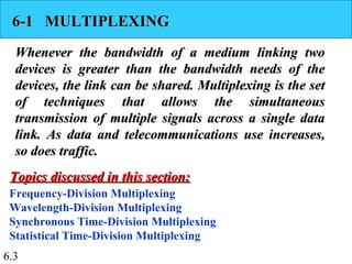
- 3. 6.3 6-1 MULTIPLEXING6-1 MULTIPLEXING Whenever the bandwidth of a medium linking twoWhenever the bandwidth of a medium linking two devices is greater than the bandwidth needs of thedevices is greater than the bandwidth needs of the devices, the link can be shared. Multiplexing is the setdevices, the link can be shared. Multiplexing is the set of techniques that allows the simultaneousof techniques that allows the simultaneous transmission of multiple signals across a single datatransmission of multiple signals across a single data link. As data and telecommunications use increases,link. As data and telecommunications use increases, so does traffic.so does traffic. Frequency-Division Multiplexing Wavelength-Division Multiplexing Synchronous Time-Division Multiplexing Statistical Time-Division Multiplexing Topics discussed in this section:Topics discussed in this section:
- 4. 6.4 Figure 6.1 Dividing a link into channels
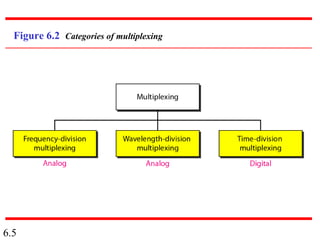
- 5. 6.5 Figure 6.2 Categories of multiplexing
- 6. 6.6 Figure 6.3 Frequency-division multiplexing
- 7. 6.7 FDM is an analog multiplexing technique that combines analog signals. Note
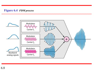
- 8. 6.8 Figure 6.4 FDM process
- 9. 6.9 Figure 6.5 FDM demultiplexing example
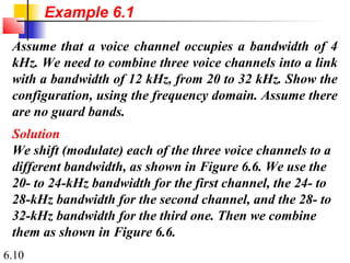
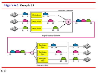
- 10. 6.10 Assume that a voice channel occupies a bandwidth of 4 kHz. We need to combine three voice channels into a link with a bandwidth of 12 kHz, from 20 to 32 kHz. Show the configuration, using the frequency domain. Assume there are no guard bands. Solution We shift (modulate) each of the three voice channels to a different bandwidth, as shown in Figure 6.6. We use the 20- to 24-kHz bandwidth for the first channel, the 24- to 28-kHz bandwidth for the second channel, and the 28- to 32-kHz bandwidth for the third one. Then we combine them as shown in Figure 6.6. Example 6.1
- 11. 6.11 Figure 6.6 Example 6.1
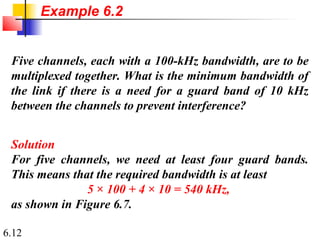
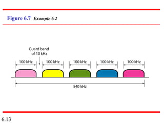
- 12. 6.12 Five channels, each with a 100-kHz bandwidth, are to be multiplexed together. What is the minimum bandwidth of the link if there is a need for a guard band of 10 kHz between the channels to prevent interference? Solution For five channels, we need at least four guard bands. This means that the required bandwidth is at least 5 × 100 + 4 × 10 = 540 kHz, as shown in Figure 6.7. Example 6.2
- 13. 6.13 Figure 6.7 Example 6.2
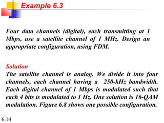
- 14. 6.14 Four data channels (digital), each transmitting at 1 Mbps, use a satellite channel of 1 MHz. Design an appropriate configuration, using FDM. Solution The satellite channel is analog. We divide it into four channels, each channel having a 250-kHz bandwidth. Each digital channel of 1 Mbps is modulated such that each 4 bits is modulated to 1 Hz. One solution is 16-QAM modulation. Figure 6.8 shows one possible configuration. Example 6.3
- 15. 6.15 Figure 6.8 Example 6.3
- 16. 6.16 Figure 6.9 Analog hierarchy
- 17. 6.17 The Advanced Mobile Phone System (AMPS) uses two bands. The first band of 824 to 849 MHz is used for sending, and 869 to 894 MHz is used for receiving. Each user has a bandwidth of 30 kHz in each direction. How many people can use their cellular phones simultaneously? Solution Each band is 25 MHz. If we divide 25 MHz by 30 kHz, we get 833.33. In reality, the band is divided into 832 channels. Of these, 42 channels are used for control, which means only 790 channels are available for cellular phone users. Example 6.4
- 18. 6.18 Figure 6.10 Wavelength-division multiplexing
- 19. 6.19 WDM is an analog multiplexing technique to combine optical signals. Note
- 20. 6.20 Figure 6.11 Prisms in wavelength-division multiplexing and demultiplexing
- 22. 6.22 TDM is a digital multiplexing technique for combining several low-rate channels into one high-rate one. Note
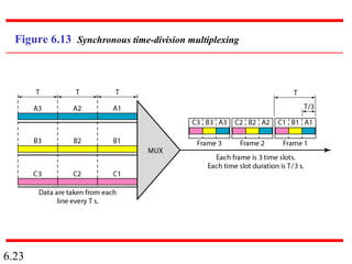
- 23. 6.23 Figure 6.13 Synchronous time-division multiplexing
- 24. 6.24 In synchronous TDM, the data rate of the link is n times faster, and the unit duration is n times shorter. Note
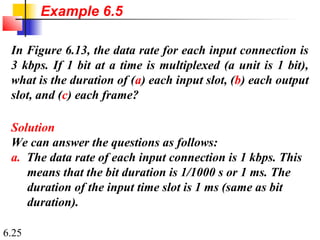
- 25. 6.25 In Figure 6.13, the data rate for each input connection is 3 kbps. If 1 bit at a time is multiplexed (a unit is 1 bit), what is the duration of (a) each input slot, (b) each output slot, and (c) each frame? Solution We can answer the questions as follows: a. The data rate of each input connection is 1 kbps. This means that the bit duration is 1/1000 s or 1 ms. The duration of the input time slot is 1 ms (same as bit duration). Example 6.5
- 26. 6.26 b. The duration of each output time slot is one-third of the input time slot. This means that the duration of the output time slot is 1/3 ms. c. Each frame carries three output time slots. So the duration of a frame is 3 × 1/3 ms, or 1 ms. The duration of a frame is the same as the duration of an input unit. Example 6.5 (continued)
- 27. 6.27 Figure 6.14 shows synchronous TDM with a data stream for each input and one data stream for the output. The unit of data is 1 bit. Find (a) the input bit duration, (b) the output bit duration, (c) the output bit rate, and (d) the output frame rate. Solution We can answer the questions as follows: a. The input bit duration is the inverse of the bit rate: 1/1 Mbps = 1 s.μ b. The output bit duration is one-fourth of the input bit duration, or ¼ s.μ Example 6.6
- 28. 6.28 c. The output bit rate is the inverse of the output bit duration or 1/(4 s) or 4 Mbps. This can also beμ deduced from the fact that the output rate is 4 times as fast as any input rate; so the output rate = 4 × 1 Mbps = 4 Mbps. d. The frame rate is always the same as any input rate. So the frame rate is 1,000,000 frames per second. Because we are sending 4 bits in each frame, we can verify the result of the previous question by multiplying the frame rate by the number of bits per frame. Example 6.6 (continued)
- 29. 6.29 Figure 6.14 Example 6.6
- 30. 6.30 Four 1-kbps connections are multiplexed together. A unit is 1 bit. Find (a) the duration of 1 bit before multiplexing, (b) the transmission rate of the link, (c) the duration of a time slot, and (d) the duration of a frame. Solution We can answer the questions as follows: a. The duration of 1 bit before multiplexing is 1 / 1 kbps, or 0.001 s (1 ms). b. The rate of the link is 4 times the rate of a connection, or 4 kbps. Example 6.7
- 31. 6.31 c. The duration of each time slot is one-fourth of the duration of each bit before multiplexing, or 1/4 ms or 250 s. Note that we can also calculate this from theμ data rate of the link, 4 kbps. The bit duration is the inverse of the data rate, or 1/4 kbps or 250 s.μ d. The duration of a frame is always the same as the duration of a unit before multiplexing, or 1 ms. We can also calculate this in another way. Each frame in this case has four time slots. So the duration of a frame is 4 times 250 s, or 1 ms.μ Example 6.7 (continued)
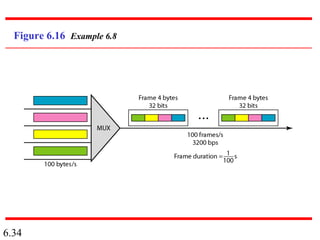
- 33. 6.33 Four channels are multiplexed using TDM. If each channel sends 100 bytes /s and we multiplex 1 byte per channel, show the frame traveling on the link, the size of the frame, the duration of a frame, the frame rate, and the bit rate for the link. Solution The multiplexer is shown in Figure 6.16. Each frame carries 1 byte from each channel; the size of each frame, therefore, is 4 bytes, or 32 bits. Because each channel is sending 100 bytes/s and a frame carries 1 byte from each channel, the frame rate must be 100 frames per second. The bit rate is 100 × 32, or 3200 bps. Example 6.8
- 34. 6.34 Figure 6.16 Example 6.8
- 35. 6.35 A multiplexer combines four 100-kbps channels using a time slot of 2 bits. Show the output with four arbitrary inputs. What is the frame rate? What is the frame duration? What is the bit rate? What is the bit duration? Solution Figure 6.17 shows the output for four arbitrary inputs. The link carries 50,000 frames per second. The frame duration is therefore 1/50,000 s or 20 s. The frame rateμ is 50,000 frames per second, and each frame carries 8 bits; the bit rate is 50,000 × 8 = 400,000 bits or 400 kbps. The bit duration is 1/400,000 s, or 2.5 s.μ Example 6.9
- 36. 6.36 Figure 6.17 Example 6.9
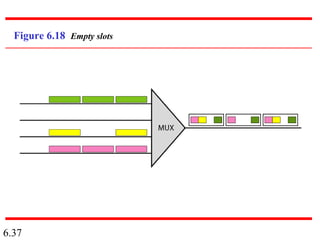
- 37. 6.37 Figure 6.18 Empty slots
- 38. 6.38 Figure 6.19 Multilevel multiplexing
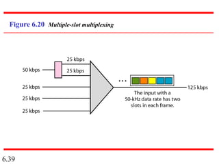
- 39. 6.39 Figure 6.20 Multiple-slot multiplexing
- 40. 6.40 Figure 6.21 Pulse stuffing
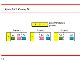
- 41. 6.41 Figure 6.22 Framing bits
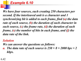
- 42. 6.42 We have four sources, each creating 250 characters per second. If the interleaved unit is a character and 1 synchronizing bit is added to each frame, find (a) the data rate of each source, (b) the duration of each character in each source, (c) the frame rate, (d) the duration of each frame, (e) the number of bits in each frame, and (f) the data rate of the link. Solution We can answer the questions as follows: a. The data rate of each source is 250 × 8 = 2000 bps = 2 kbps. Example 6.10
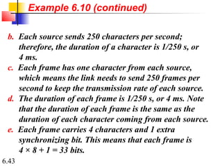
- 43. 6.43 b. Each source sends 250 characters per second; therefore, the duration of a character is 1/250 s, or 4 ms. c. Each frame has one character from each source, which means the link needs to send 250 frames per second to keep the transmission rate of each source. d. The duration of each frame is 1/250 s, or 4 ms. Note that the duration of each frame is the same as the duration of each character coming from each source. e. Each frame carries 4 characters and 1 extra synchronizing bit. This means that each frame is 4 × 8 + 1 = 33 bits. Example 6.10 (continued)
- 44. 6.44 Two channels, one with a bit rate of 100 kbps and another with a bit rate of 200 kbps, are to be multiplexed. How this can be achieved? What is the frame rate? What is the frame duration? What is the bit rate of the link? Solution We can allocate one slot to the first channel and two slots to the second channel. Each frame carries 3 bits. The frame rate is 100,000 frames per second because it carries 1 bit from the first channel. The bit rate is 100,000 frames/s × 3 bits per frame, or 300 kbps. Example 6.11
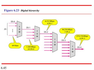
- 45. 6.45 Figure 6.23 Digital hierarchy
- 46. 6.46 Table 6.1 DS and T line rates
- 47. 6.47 Figure 6.24 T-1 line for multiplexing telephone lines
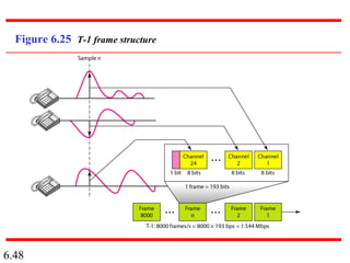
- 48. 6.48 Figure 6.25 T-1 frame structure
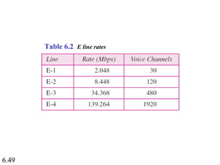
- 49. 6.49 Table 6.2 E line rates
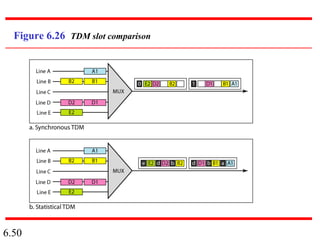
- 50. 6.50 Figure 6.26 TDM slot comparison
- 51. 6.51 6-1 SPREAD SPECTRUM6-1 SPREAD SPECTRUM In spread spectrum (SS), we combine signals fromIn spread spectrum (SS), we combine signals from different sources to fit into a larger bandwidth, but ourdifferent sources to fit into a larger bandwidth, but our goals are to prevent eavesdropping and jamming. Togoals are to prevent eavesdropping and jamming. To achieve these goals, spread spectrum techniques addachieve these goals, spread spectrum techniques add redundancy.redundancy. Frequency Hopping Spread Spectrum (FHSS) Direct Sequence Spread Spectrum Synchronous (DSSS) Topics discussed in this section:Topics discussed in this section:
- 52. 6.52 Figure 6.27 Spread spectrum
- 53. 6.53 Figure 6.28 Frequency hopping spread spectrum (FHSS)
- 54. 6.54 Figure 6.29 Frequency selection in FHSS
- 55. 6.55 Figure 6.30 FHSS cycles
- 56. 6.56 Figure 6.31 Bandwidth sharing
- 58. 6.58 Figure 6.33 DSSS example