Solucion ejercicios beer
3 likes1,322 views

This document contains 13 multi-step solutions to mechanics problems involving blocks on inclined planes with tensions in cords or cables. The solutions include free body diagrams, identification of relevant forces, and setup and solution of static equilibrium equations to determine minimum tensions, angles of impending motion, or other requested values. Key values or relationships are determined numerically in some cases.


![COSMOS: Complete Online Solutions Manual Organization System
Vector Mechanics for Engineers: Statics and Dynamics, 8/e, Ferdinand P. Beer, E. Russell Johnston, Jr.,
Elliot R. Eisenberg, William E. Clausen, David Mazurek, Phillip J. Cornwell
© 2007 The McGraw-Hill Companies.
Chapter 8, Solution 34.
FBD Collar:
Impending motion down:
Impending motion up:
Stretch of spring
cos
a
x AB a a
θ
= − = −
( )( )
1
1.5 kN/m 0.5 m 1
cos cos
s
a
F kx k a
θ θ
= = − = −
( )
1
0.75 kN 1
cosθ
= −
0: cos 0x sF N F θΣ = − =
( )( )cos 0.75 kN 1 cossN F θ θ= = −
Impending slip: ( )( )( )0.4 0.75 kN 1 cossF Nµ θ= = −
( )( )0.3 kN 1 cosθ= −
+ down, – up
0: sin 0y sF F F WθΣ = ± − =
( )( ) ( )( )0.75 kN tan sin 0.3 kN 1 cos 0Wθ θ θ− ± − − =
or ( ) ( ) ( )[ ]0.3 kN 2.5 tan sin 1 cosW θ θ θ= − ± −
with 30 :θ = ° ( )up 0.01782 kN OKW =
( )down 0.0982 kN OKW =
Equilibrium if 17.82 N 98.2 NW≤ ≤](https://image.slidesharecdn.com/solucionejerciciosbeer-151023035840-lva1-app6891/85/Solucion-ejercicios-beer-34-320.jpg)


![COSMOS: Complete Online Solutions Manual Organization System
Vector Mechanics for Engineers: Statics and Dynamics, 8/e, Ferdinand P. Beer, E. Russell Johnston, Jr.,
Elliot R. Eisenberg, William E. Clausen, David Mazurek, Phillip J. Cornwell
© 2007 The McGraw-Hill Companies.
Chapter 8, Solution 92.
Let the normal force on A∆ be ,N∆ and
N k
A r
∆
=
∆
As in the text ,F N M r Fµ∆ = ∆ ∆ = ∆
The total normal force
2
0 00
lim
R
A
k
P N rdr d
r
π
θ
∆ →
= Σ∆ =
∫ ∫
( )0
2 2 or
2
R P
P kdr kR k
R
π π
π
= = =∫
The total couple
2
worn 0 00
lim
R
A
k
M M r rdr d
r
π
µ θ
∆ →
= Σ∆ =
∫ ∫
2 2
worn 0
2 2 2
2 2 2
R R P R
M k rdr k
R
πµ πµ πµ
π
= = =∫
or worn
1
2
M PRµ=
Now new
2
3
M PRµ= [Eq. (8.9)]
Thus
1
worn 2
2
new 3
3
75%
4
PRM
M PR
µ
µ
= = =](https://image.slidesharecdn.com/solucionejerciciosbeer-151023035840-lva1-app6891/85/Solucion-ejercicios-beer-96-320.jpg)


Solucion ejercicios beer
- 1. COSMOS: Complete Online Solutions Manual Organization System Vector Mechanics for Engineers: Statics and Dynamics, 8/e, Ferdinand P. Beer, E. Russell Johnston, Jr., Elliot R. Eisenberg, William E. Clausen, David Mazurek, Phillip J. Cornwell © 2007 The McGraw-Hill Companies. Chapter 8, Solution 1. FBD Block B: Tension in cord is equal to lb25=AW from FBD’s of block A and pulley. 0: cos30 0,y BF N WΣ = − ° = cos30BW= °N (a) For smallest ,BW slip impends up the incline, and 0.35 cos30s BF N Wµ= = ° 0:xFΣ = 25 lb sin30 0BF W− + ° = ( )0.35cos30 sin30 25 lbBW° + ° = min 31.1 lbBW = (b) For largest ,BW slip impends down the incline, and 0.35 cos30s BF N Wµ= − = − ° 0: sin30 25 lb 0x s BF F WΣ = + ° − = ( )sin30 0.35cos30 25 lbBW° − ° = lb0.127max =BW
- 2. COSMOS: Complete Online Solutions Manual Organization System Vector Mechanics for Engineers: Statics and Dynamics, 8/e, Ferdinand P. Beer, E. Russell Johnston, Jr., Elliot R. Eisenberg, William E. Clausen, David Mazurek, Phillip J. Cornwell © 2007 The McGraw-Hill Companies. Chapter 8, Solution 2. FBD Block B: Tension in cord is equal to 40 lbAW = from FBD’s of block A and pulley. (a) ( )0: 52 lb cos25 0,yF NΣ = − ° = 47.128 lb=N ( )max 0.35 47.128 lb 16.495 lbsF Nµ= = = ( )eq0: 40 lb 52 lb sin 25 0xF FΣ = − + ° = So, for equilibrium, lb024.18eq =F Since eq max,F F> the block must slip (up since F > 0) ∴There is no equilibrium (b) With slip, ( )0.25 47.128 lbkF Nµ= = 11.78 lb=F 35°
- 3. COSMOS: Complete Online Solutions Manual Organization System Vector Mechanics for Engineers: Statics and Dynamics, 8/e, Ferdinand P. Beer, E. Russell Johnston, Jr., Elliot R. Eisenberg, William E. Clausen, David Mazurek, Phillip J. Cornwell © 2007 The McGraw-Hill Companies. Chapter 8, Solution 3. FBD Block: Tension in cord is equal to 40 N,P = from FBD of pulley. ( )( )2 10 kg 9.81 m/s 98.1 N= =W ( ) ( ) 020sinN4020cosN1.98:0 =°+°−=Σ NFy 78.503 NN = ( )( )max 0.30 78.503 N 23.551 NsF Nµ= = = For equilibrium: ( ) ( )0: 40 N cos20 98.1 N sin 20 0xF FΣ = ° − ° − = eq max4.0355 N , Equilibrium existsF F= < ∴ eqF F= 4.04 N=F 20°
- 4. COSMOS: Complete Online Solutions Manual Organization System Vector Mechanics for Engineers: Statics and Dynamics, 8/e, Ferdinand P. Beer, E. Russell Johnston, Jr., Elliot R. Eisenberg, William E. Clausen, David Mazurek, Phillip J. Cornwell © 2007 The McGraw-Hill Companies. Chapter 8, Solution 4. Tension in cord is equal to 62.5 N,P = from FBD of pulley. ( )( )2 10 kg 9.81 m/s 98.1 N= =W ( ) ( )0: 98.1 N cos20 62.5 N sin15 0yF NΣ = − ° + ° = 76.008 NN = ( )( )max 0.30 76.008 N 22.802 NsF Nµ= = = For equilibrium: ( ) ( )0: 62.5 N cos15 98.1 N sin 20 0xF FΣ = ° − ° − = eq max26.818 N so no equilibrium,F F= > and block slides up the incline ( )( )slip 0.25 76.008 N 19.00 NxF Nµ= = = 19.00 N=F 20°
- 5. COSMOS: Complete Online Solutions Manual Organization System Vector Mechanics for Engineers: Statics and Dynamics, 8/e, Ferdinand P. Beer, E. Russell Johnston, Jr., Elliot R. Eisenberg, William E. Clausen, David Mazurek, Phillip J. Cornwell © 2007 The McGraw-Hill Companies. Chapter 8, Solution 5. Tension in cord is equal to P from FBD of pulley. ( )( )2 10 kg 9.81 m/s 98.1 N= =W ( )0: 98.1 N cos20 sin 25 0yF N PΣ = − ° + ° = (1) ( )0: cos25 98.1 N sin 20 0xF P FΣ = ° − ° + = (2) For impending slip down the incline, 0.3 NsF Nµ= = and solving (1) and (2), 7.56 NDP = For impending slip up the incline, 0.3 NsF Nµ= − = − and solving (1) and (2), 59.2 NUP = so, for equilibrium 7.56 N 59.2 NP≤ ≤
- 6. COSMOS: Complete Online Solutions Manual Organization System Vector Mechanics for Engineers: Statics and Dynamics, 8/e, Ferdinand P. Beer, E. Russell Johnston, Jr., Elliot R. Eisenberg, William E. Clausen, David Mazurek, Phillip J. Cornwell © 2007 The McGraw-Hill Companies. Chapter 8, Solution 6. FBD Block: ( )( )2 20 kg 9.81 m/s 196.2 N= =W For minθ motion will impend up the incline, so F is downward and sF Nµ= ( ) ( )0: 220 N sin 196.2 N cos35 0yF N θΣ = − − ° = ( )0.3 220 sin 196.2 cos35 NsF Nµ θ= = + ° (1) ( ) ( )0: 220 N cos 196.2 N sin35 0xF FθΣ = − − ° = (2) ( ) ( ) ( )1 2 : 0.3 220 sin 196.2cos Nθ θ+ + ( ) ( )220 cos N 196.2sin35 Nθ= − ° or 220cos 66sin 160.751θ θ− = Solving numerically: 28.9θ = °
- 7. COSMOS: Complete Online Solutions Manual Organization System Vector Mechanics for Engineers: Statics and Dynamics, 8/e, Ferdinand P. Beer, E. Russell Johnston, Jr., Elliot R. Eisenberg, William E. Clausen, David Mazurek, Phillip J. Cornwell © 2007 The McGraw-Hill Companies. Chapter 8, Solution 7. FBD Block: For minP motion will impend down the incline, and the reaction force R will make the angle ( )1 1 tan tan 0.35 19.2900s sφ µ− − = = = ° with the normal, as shown. Note, for minimum P, P must be ⊥ to R, i.e. sβ φ= (angle between P and x equals angle between R and normal). (b) 19.29β = ° then ( ) ( )160 N cos 40P β= + ° ( )160 N cos59.29 81.71 N= ° = (a) min 81.7 NP =
- 8. COSMOS: Complete Online Solutions Manual Organization System Vector Mechanics for Engineers: Statics and Dynamics, 8/e, Ferdinand P. Beer, E. Russell Johnston, Jr., Elliot R. Eisenberg, William E. Clausen, David Mazurek, Phillip J. Cornwell © 2007 The McGraw-Hill Companies. Chapter 8, Solution 8. FBD block (impending motion downward) ( )1 1 tan tan 0.25 14.036s sφ µ− − = = = ° (a) Note: For minimum P, ⊥P R So ( )90 30 14.036 45.964β α= = ° − ° + ° = ° and ( ) ( ) ( )30 lb sin 30 lb sin 45.964 21.567 lbP α= = ° = 21.6 lbP = (b) 46.0β = °
- 9. COSMOS: Complete Online Solutions Manual Organization System Vector Mechanics for Engineers: Statics and Dynamics, 8/e, Ferdinand P. Beer, E. Russell Johnston, Jr., Elliot R. Eisenberg, William E. Clausen, David Mazurek, Phillip J. Cornwell © 2007 The McGraw-Hill Companies. Chapter 8, Solution 9. FBD Block: For impending motion. ( )1 1 tan tan 0.40s sφ µ− − = = 21.801sφ = ° Note 1,2 1,2 sβ θ φ= − From force triangle: s 1,2 10 lb 15 lb sin sinφ β = ( )1 1,2 33.85415 lb sin sin 21.801 10 lb 146.146 β − ° = ° = ° So 1,2 1,2 55.655 167.947 sθ β φ ° = + = ° So (a) equilibrium for 0 55.7θ≤ ≤ ° (b) equilibrium for 167.9 180θ° ≤ ≤ °
- 10. COSMOS: Complete Online Solutions Manual Organization System Vector Mechanics for Engineers: Statics and Dynamics, 8/e, Ferdinand P. Beer, E. Russell Johnston, Jr., Elliot R. Eisenberg, William E. Clausen, David Mazurek, Phillip J. Cornwell © 2007 The McGraw-Hill Companies. Chapter 8, Solution 10. FBD A with pulley: FBD E with pulley: Tension in cord is T throughout from pulley FBD’s 0: 2 20 lb = 0,yF TΣ = − 10 lbT = For max,θ motion impends to right, and ( )1 1 tan tan 0.35 19.2900s sφ µ− − = = = ° From force triangle, ( ) ( ) 20 lb 10 lb , 2sin sin sin sin s s s s φ θ φ θ φ φ = = − − ( )1 sin 2sin19.2900 19.2900 60.64θ − = ° + ° − ° max 60.6θ = °
- 11. COSMOS: Complete Online Solutions Manual Organization System Vector Mechanics for Engineers: Statics and Dynamics, 8/e, Ferdinand P. Beer, E. Russell Johnston, Jr., Elliot R. Eisenberg, William E. Clausen, David Mazurek, Phillip J. Cornwell © 2007 The McGraw-Hill Companies. Chapter 8, Solution 11. FBD top block: FBD bottom block: FBD block: 10: 196.2 N 0yF NΣ = − = 1 196.2 N=N (a) With cable in place, impending motion of bottom block requires impending slip between blocks, so ( )1 1 0.4 196.2 NsF Nµ= = 1 78.48 N=F 20: 196.2 N 294.3 N 0yF NΣ = − − = 2 490.5 N=N ( )2 2 0.4 490.5 N 196.2 NsF Nµ= = = 0: 78.48 N 196.2 N 0xF PΣ = − + + = 275 N=P (b) Without cable AB, top and bottom blocks will move together 0: 490.5 N 0, 490.5 NyF N NΣ = − = = Impending slip: ( )0.40 490.5 N 196.2 NsF Nµ= = = 0: 196.2 N 0xF PΣ = − + = 196.2 N=P
- 12. COSMOS: Complete Online Solutions Manual Organization System Vector Mechanics for Engineers: Statics and Dynamics, 8/e, Ferdinand P. Beer, E. Russell Johnston, Jr., Elliot R. Eisenberg, William E. Clausen, David Mazurek, Phillip J. Cornwell © 2007 The McGraw-Hill Companies. Chapter 8, Solution 12. FBD top block: FBD bottom block: FBD block: Note that, since ( )1 1 tan tan 0.40 21.8 15 ,s sφ µ− − = = = ° > ° no motion will impend if 0,P = with or without cable AB. (a) With cable, impending motion of bottom block requires impending slip between blocks, so 1 sF Nµ= 1 10: cos15 0,yF N W′Σ = − ° = 1 1 cos15 189.515 NN W= ° = ( )1 1 1 10.40 cos15 0.38637sF N W Wµ= = ° = 1 75.806 N=F 0:xF ′Σ = 1 1 sin15 0T F W− − ° = 75.806 N 50.780 N 126.586 NT = + = ( )( )2 2 30 kg 9.81 m/s 294.3 NW = = ( ) ( )20 : 189.515 N cos 15 294.3 NyF NΣ = − ° − ( )75.806 N sin15 0+ ° = 2 457.74 N=N ( )( )2 2 0.40 457.74 N 183.096 NsF Nµ= = = ( ) ( )0: 189.515 N 75.806 N cos15xF PΣ = − + + ° 126.586 N 183.096 N 0+ + = 361 N=P (b) Without cable, blocks remain together 1 20: 0yF N W WΣ = − − = 196.2 N 294.3 NN = + 490.5 N= ( )( )0.40 490.5 N 196.2 NsF Nµ= = = 0: 196.2 N 0xF PΣ = − + = 196.2 N=P
- 13. COSMOS: Complete Online Solutions Manual Organization System Vector Mechanics for Engineers: Statics and Dynamics, 8/e, Ferdinand P. Beer, E. Russell Johnston, Jr., Elliot R. Eisenberg, William E. Clausen, David Mazurek, Phillip J. Cornwell © 2007 The McGraw-Hill Companies. Chapter 8, Solution 13. FBD A: FBD B: Note that slip must impend at both surfaces simultaneously. 10: N sin 16 lb = 0yF T θΣ = + − 1 16 lb sinN T θ= − Impending slip: ( )( )1 1 0.20 16 lb sinsF N Tµ θ= = − ( )1 3.2 lb 0.2 sinF T θ= − (1) 10: cos 0xF F T θΣ = − = (2) 2 1 2 10: 24 lb 0, 24 lbyF N N N NΣ = − − = = + 30 lb sinT θ= − Impending slip: ( )( )2 2 0.20 30 lb sinsF N Tµ θ= = − 6 lb 0.2 sinT θ= − 1 20: 10 lb 0xF F FΣ = − − = ( ) ( ) ( )1 2 1 110 lb 0.2 24 lbs N N N Nµ = + = + + 1 110 lb 0.4 N 4.8 lb, 13 lbN= + = Then ( )( )1 1 0.2 13 lb 2.6 lbsF Nµ= = = Then ( )1 : sin 3.0 lbT θ = ( )2 : cos 2.6 lbT θ = Dividing 13 3 tan , tan 49.1 2.6 2.6 θ θ − = = = ° 49.1θ = °
- 14. COSMOS: Complete Online Solutions Manual Organization System Vector Mechanics for Engineers: Statics and Dynamics, 8/e, Ferdinand P. Beer, E. Russell Johnston, Jr., Elliot R. Eisenberg, William E. Clausen, David Mazurek, Phillip J. Cornwell © 2007 The McGraw-Hill Companies. Chapter 8, Solution 14. FBD’s: A: B: Note: Slip must impend at both surfaces simultaneously. 1 10: 20 lb 0, 20 lbyF N NΣ = − = = Impending slip: ( )( )1 1 0.25 20 lb 5 lbsF Nµ= = = 0: 5 lb 0, 5 lbxF T TΣ = − + = = ( ) ( )20: 20 lb + 40 lb cos 5 lb sin 0yF N θ θ′Σ = − − = ( ) ( )2 60 lb cos 5 lb sinN θ θ= − Impending slip: ( )( )2 2 0.25 60cos 5sin lbsF Nµ θ θ= = − ( ) ( )20: 5 lb 5 lb cos 20 lb 40 lb sin 0xF F θ θ′Σ = − − − + + = 20cos 58.75sin 5 0θ θ− + − = Solving numerically, 23.4θ = °
- 15. COSMOS: Complete Online Solutions Manual Organization System Vector Mechanics for Engineers: Statics and Dynamics, 8/e, Ferdinand P. Beer, E. Russell Johnston, Jr., Elliot R. Eisenberg, William E. Clausen, David Mazurek, Phillip J. Cornwell © 2007 The McGraw-Hill Companies. Chapter 8, Solution 15. FBD: For impending tip the floor reaction is at C. ( )( )2 40 kg 9.81 m/s 392.4 N= =W For impending slip ( )1 1 tan tan 0.35s sφ φ µ− − = = = 19.2900φ = ° 0.8 m 0.4 m tan , 1.14286 m 0.35 EG EG φ = = = 0.5 m 0.64286 mEF EG= − = (a) 1 1 0.64286 m tan tan 58.109 0.4 m 0.4 m s EF α − − = = = ° 58.1sα = ° (b) sin19.29 sin128.820 P W = ° ( )( )392.4 N 0.424 166.379 NP = = 166.4 NP = Once slipping begins, φ will reduce to 1 tan .k kφ µ− = Then maxα will increase.
- 16. COSMOS: Complete Online Solutions Manual Organization System Vector Mechanics for Engineers: Statics and Dynamics, 8/e, Ferdinand P. Beer, E. Russell Johnston, Jr., Elliot R. Eisenberg, William E. Clausen, David Mazurek, Phillip J. Cornwell © 2007 The McGraw-Hill Companies. Chapter 8, Solution 16. First assume slip impends without tipping, so sF Nµ= FBD 0: sin 40 0, sin 40yF N P W N W PΣ = + ° − = = − ° ( )0.35 sin 40sF N W Pµ= = − ° 0: cos40 0xF F PΣ = − ° = ( )0.35 cos40 0.35sin 40W P= ° + ° 0.35317sP W= (1) Next assume tip impends without slipping, R acts at C. ( ) ( ) ( )0: 0.8 m sin 40 0.5 m cos40 0.4 m 0AM P P WΣ = ° + ° − = 0.4458t sP W P= > from (1) ( )( )2 max 0.35317 40 kg 9.81 m/ssP P∴ = = 138.584 N= (a) max 138.6 NP = (b) Slip is impending
- 17. COSMOS: Complete Online Solutions Manual Organization System Vector Mechanics for Engineers: Statics and Dynamics, 8/e, Ferdinand P. Beer, E. Russell Johnston, Jr., Elliot R. Eisenberg, William E. Clausen, David Mazurek, Phillip J. Cornwell © 2007 The McGraw-Hill Companies. Chapter 8, Solution 17. FBD Cylinder: For maximum M, motion impends at both A and B ;A A A B B BF N F Nµ µ= = 0: 0x A B A B B BF N F N F NµΣ = − = = = A A A A B BF N Nµ µ µ= = ( )0: 0 1y B A B A BF N F W N Wµ µΣ = + − = + = or 1 1 B A B N W µ µ = + and 1 B B B B A B F N W µ µ µ µ = = + 1 A B A A B B A B F N W µ µ µ µ µ µ = = + ( ) 1 0: 0 1 A C A B B A B M M r F F M Wr µ µ µ µ + Σ = − + = = + (a) For 0 and 0.36A Bµ µ= = 0.360M Wr= (b) For 0.30 and 0.36A Bµ µ= = 0.422M Wr=
- 18. COSMOS: Complete Online Solutions Manual Organization System Vector Mechanics for Engineers: Statics and Dynamics, 8/e, Ferdinand P. Beer, E. Russell Johnston, Jr., Elliot R. Eisenberg, William E. Clausen, David Mazurek, Phillip J. Cornwell © 2007 The McGraw-Hill Companies. Chapter 8, Solution 18. FBD’s: (a) FBD Drum: 10 0: ft 50 lb ft 0 12 DM F Σ = − ⋅ = 60 lbF = Impending slip: 60 lb 150 lb 0.40s F N µ = = = FBD arm: ( ) ( ) ( )0: 6 in. 6 in. 18 in. 0AM C F NΣ = + − = ( )60 lb + 3 150 lb 390 lbC = − = cw 390 lbC = (b) Reversing the 50 lb ft⋅ couple reverses the direction of F, but the magnitudes of F and N are not changed. Then, using the FBD arm: ( ) ( ) ( )0: 6 in. 6 in. 18 in. 0AM C F NΣ = − − = ( )60 lb 3 150 lb 510 lbC = + = ccw 510 lbC =
- 19. COSMOS: Complete Online Solutions Manual Organization System Vector Mechanics for Engineers: Statics and Dynamics, 8/e, Ferdinand P. Beer, E. Russell Johnston, Jr., Elliot R. Eisenberg, William E. Clausen, David Mazurek, Phillip J. Cornwell © 2007 The McGraw-Hill Companies. Chapter 8, Solution 19. FBD’s: For slipping, 0.30 NkF Nµ= = (a) For cw rotation of drum, the friction force F is as shown. From FBD arm: ( )( ) ( ) ( )0: 6 in. 600 lb 6 in. 18 in. 0AM F NΣ = + − = 600 lb + 3 0 0.30 F F − = 600 lb 9 F = Moment about ( )10 in. 666.67 lb in.D F= = ⋅ cw = 55.6 lb ft⋅M (b) For ccw rotation of drum, the friction force F is reversed ( )( ) ( ) ( )0: 6 in. 600 lb 6 in. 18 in. 0AM F NΣ = − − = 600 lb 3 0 0.30 F F− − = 600 lb 11 F = Moment about 10 600 ft lb 45.45 lb ft 12 11 D = = ⋅ ccw 45.5 lb ft= ⋅M
- 20. COSMOS: Complete Online Solutions Manual Organization System Vector Mechanics for Engineers: Statics and Dynamics, 8/e, Ferdinand P. Beer, E. Russell Johnston, Jr., Elliot R. Eisenberg, William E. Clausen, David Mazurek, Phillip J. Cornwell © 2007 The McGraw-Hill Companies. Chapter 8, Solution 20. FBD: (a) ( )0: 0,CM r F T T FΣ = − = = Impending slip: sF Nµ= or s s F T N µ µ = = ( )0: cos 25 sin 25 0xF F T WθΣ = + ° + − ° = ( )1 cos 25 sin 25T Wθ + ° + = ° (1) ( )0: cos25 sin 25 0yF N W T θΣ = − ° + ° + = ( ) 1 sin 25 cos25 0.35 T Wθ + ° + = ° (2) Dividing (1) by (2): ( ) ( ) 1 cos 25 tan 25 1 sin 25 0.35 θ θ + ° + = ° + ° + Solving numerically, 25 42.53θ° + = ° 17.53θ = ° (b) From (1) ( )1 cos42.53 sin 25T W+ ° = ° 0.252T W=
- 21. COSMOS: Complete Online Solutions Manual Organization System Vector Mechanics for Engineers: Statics and Dynamics, 8/e, Ferdinand P. Beer, E. Russell Johnston, Jr., Elliot R. Eisenberg, William E. Clausen, David Mazurek, Phillip J. Cornwell © 2007 The McGraw-Hill Companies. Chapter 8, Solution 21. FBD ladder: Note: slope of ladder 4.5 m 12 , 1.875 m 5 = = so ( ) 13 4.5 m 4.875 12 AC = = 6.5 m,L = so 4.875 m 3 1 , 6.5 m 4 2 AC L AD L= = = and 1 4 DC BD L= = For impending slip: ,A s A C s CF N F Nµ µ= = Also 1 12 tan 15 52.380 5 θ − = − ° = ° 0: sin15 cos sin 0x A C CF F W F Nθ θΣ = − ° + − = 10 10 sin15 cos sin 39 39 A sF W W Wµ θ θ= ° − + ( )0.46192 0.15652 s Wµ= − 0: cos15 sin cos 0y A C CF N W F Nθ θΣ = − ° + + = 10 10 cos15 sin cos 39 39 A sN W W Wµ θ θ= ° − − ( )0.80941 0.20310 s Wµ= − But 2 : 0.46192 0.15652 0.80941 0.20310A A s s sF Nµ µ µ µ= − = − 2 4.7559 2.2743s sµ µ− + 0.539,sµ = 4.2166 min 0.539sµ =
- 22. COSMOS: Complete Online Solutions Manual Organization System Vector Mechanics for Engineers: Statics and Dynamics, 8/e, Ferdinand P. Beer, E. Russell Johnston, Jr., Elliot R. Eisenberg, William E. Clausen, David Mazurek, Phillip J. Cornwell © 2007 The McGraw-Hill Companies. Chapter 8, Solution 22. FBD ladder: Slip impends at both A and B, ,A s AF Nµ= B s BF Nµ= 0: 0,x A B B A s AF F N N F NµΣ = − = = = 0: 0,y A B A BF N W F N F WΣ = − + = + = A s BN N Wµ+ = ( )2 1A sN Wµ+ = ( ) 5 5 0: 6 m m m 0 4 2 O B AM N W N Σ = + − = ( )25 5 6 1 0 4 2 s A A s AN N Nµ µ+ + − = 2 24 1 0 5 s sµ µ+ − = 2.4 2.6sµ = − ± min 0.200sµ =
- 23. COSMOS: Complete Online Solutions Manual Organization System Vector Mechanics for Engineers: Statics and Dynamics, 8/e, Ferdinand P. Beer, E. Russell Johnston, Jr., Elliot R. Eisenberg, William E. Clausen, David Mazurek, Phillip J. Cornwell © 2007 The McGraw-Hill Companies. Chapter 8, Solution 23. FBD rod: (a) Geometry: cos cos tan 2 2 L L BE DEθ θ β = = cos sin 2 tan s L EF L DF θ θ φ = = So 1 cos cos tan sin 2 2 tan s L L θ θ β θ φ + = or 1 1 1 tan 2tan 2.5 tan 0.4s s β θ φ µ + = = = = (1) Also, sin sinL L Lθ β+ = or sin sin 1θ β+ = (2) Solving Eqs. (1) and (2) numerically 1 14.62 66.85θ β= ° = ° 2 248.20 14.75θ β= ° = ° Therefore, 4.62 and 48.2θ θ= ° = ° (b) Now 1 1 tan tan 0.4 21.801s sφ µ− − = = = ° and ( )sin sin 90s s T W φ β φ = + − or ( ) sin sin 90 s s T W φ β φ = + − For 4.62 0.526T Wθ = ° = 48.2 0.374T Wθ = ° =
- 24. COSMOS: Complete Online Solutions Manual Organization System Vector Mechanics for Engineers: Statics and Dynamics, 8/e, Ferdinand P. Beer, E. Russell Johnston, Jr., Elliot R. Eisenberg, William E. Clausen, David Mazurek, Phillip J. Cornwell © 2007 The McGraw-Hill Companies. Chapter 8, Solution 24. FBD: Assume the weight of the slender rod is negligible compared to P. First consider impending slip upward at B. The friction forces will be directed as shown and , ,B C s B CF Nµ= ( )0: sin 0 sin B C a M L P Nθ θ Σ = − = 2 sinC L N P a θ= 0: sin cos 0x C C BF N F Nθ θΣ = + − = ( )sin cosC s BN Nθ µ θ+ = so ( )2 sin sin cosB s L N P a θ θ µ θ= + 0: cos sin 0y C C BF P N F Fθ θΣ = − + − − = cos sinC s C s BP N N Nθ µ θ µ= − − so ( ) ( )2 2 sin cos sin sin sin coss s s L L P P P a a θ θ µ θ µ θ θ µ θ= − − + (1) Using 35θ = ° and 0.20, solve for 13.63.s L a µ = = To consider impending slip downward at B, the friction forces will be reversed. This can be accomplished by substituting 0.20 insµ = − equation (1). Then solve for 3.46. L a = Thus, equilibrium is maintained for 3.46 13.63 L a ≤ ≤
- 25. COSMOS: Complete Online Solutions Manual Organization System Vector Mechanics for Engineers: Statics and Dynamics, 8/e, Ferdinand P. Beer, E. Russell Johnston, Jr., Elliot R. Eisenberg, William E. Clausen, David Mazurek, Phillip J. Cornwell © 2007 The McGraw-Hill Companies. Chapter 8, Solution 25. FBD ABC: ( ) ( )0: 0.045 m + 0.30 m sin30 400 N sin30CM Σ = ° ° ( ) ( )0.030 m + 0.30 m cos30 400 N cos30 + ° ° ( ) ( ) 12 5 0.03 m 0.045 m 0 13 13 BD BDF F − − = 3097.64 NBDF = FBD Blade: ( ) 25 0: 3097.6 N 0 1191.4 65 xF N NΣ = − = = ( )0.20 1191.4 N 238.3 NsF Nµ= = = ( ) 60 0: 3097.6 N 0 65 yF P FΣ = + − = 2859.3 238.3 2621.0 NP = − = Force by blade 2620 N=P
- 26. COSMOS: Complete Online Solutions Manual Organization System Vector Mechanics for Engineers: Statics and Dynamics, 8/e, Ferdinand P. Beer, E. Russell Johnston, Jr., Elliot R. Eisenberg, William E. Clausen, David Mazurek, Phillip J. Cornwell © 2007 The McGraw-Hill Companies. Chapter 8, Solution 26. FBD CD: Note: The plate is a 3-force member, and for minimum ,sµ slip impends at C and D, so the reactions there are at angle sφ from the normal. From the FBD, OCG 20 sφ= ° + and ODG 20 sφ= ° − Then ( ) ( )0.5 in. tan 20 sOG φ= ° + and ( ) 1.2 in. 0.5 in. tan 20 sin70 sOG φ = + ° − ° Equating, ( ) ( )tan 20 3.5540tan 20s sφ φ° + = ° − Solving numerically, 10.5652sφ = ° ( )tan tan 10.5652s sµ φ= = ° 0.1865sµ =
- 27. COSMOS: Complete Online Solutions Manual Organization System Vector Mechanics for Engineers: Statics and Dynamics, 8/e, Ferdinand P. Beer, E. Russell Johnston, Jr., Elliot R. Eisenberg, William E. Clausen, David Mazurek, Phillip J. Cornwell © 2007 The McGraw-Hill Companies. Chapter 8, Solution 27. FBD pin A: From FBD Whole the force at 750 lbA = ( ) 4 0: 0, 5 x AB AB AB ABF F F F F′ ′Σ = − = = 3 0: 750 lb 2 0, 625 lb 5 y AB ABF F FΣ = − = = FBD Casting: 0: 0,x D D D DF N N N N N′ ′Σ = − = = = Impending slip , or D D D D D s F F F N Nµ µ ′= = = 0: 2 750 lb 0, 375 lby D DF F FΣ = − = = 375 lb D s N µ = FBD ABCD: ( ) ( ) ( ) ( ) 4 0: 12 in. 6 in. 42.75 in. 625 lb 0 5 CM N FΣ = − − = ( ) ( )( ) ( ) ( ) 375 lb 4 12 in. 6 in. 375 lb 42.75 in. 625 lb 0 5sµ = + = 0.1900sµ =
- 28. COSMOS: Complete Online Solutions Manual Organization System Vector Mechanics for Engineers: Statics and Dynamics, 8/e, Ferdinand P. Beer, E. Russell Johnston, Jr., Elliot R. Eisenberg, William E. Clausen, David Mazurek, Phillip J. Cornwell © 2007 The McGraw-Hill Companies. Chapter 8, Solution 28. From FBD Whole, and neglecting weight of clamp compared to 550 lb plate, = −P W Since AB is a two-force member, B is vertical and .B W= FBD BCD: ( ) ( )0: 1.85 in. 2.3 in. cos40CM W DΣ = − ° ( )0.3 in. sin 40 0, 0.94642D D W− ° = = FBD EG: ( ) ( ) ( )0: 0.9 in. 1.3 in. 1.3 in. cos40 0E G G DM N F NΣ = − − ° = Impending slip: G s GF Nµ= Solving: ( )0.9 1.3 0.94250s GN Wµ− = (1) FBD Plate: By symmetry ,G G G G s GN N F F Nµ′ ′= = = 0: 2 0, , 2 2 y G G G s W W F F W F N µ Σ = − = = = Substitute in (1): ( )0.9 1.3 0.94250 2 s s W Wµ µ − = Solving, 0.283,sµ = sm 0.283µ =
- 29. COSMOS: Complete Online Solutions Manual Organization System Vector Mechanics for Engineers: Statics and Dynamics, 8/e, Ferdinand P. Beer, E. Russell Johnston, Jr., Elliot R. Eisenberg, William E. Clausen, David Mazurek, Phillip J. Cornwell © 2007 The McGraw-Hill Companies. Chapter 8, Solution 29. FBD table + child: ( )2 18 kg 9.81m/s 176.58 NCW = = ( )2 16 kg 9.81m/s 156.96 NTW = = (a) Impending tipping about , 0, andF FE N F= = ( )( ) ( )( ) ( ) ( )0: 0.05 m 176.58 N 0.4 m 156.96 N 0.5 m cos 0.7 m sin 0EM P Pθ θΣ = − + − = 33cos 46.2sin 53.955θ θ− = Solving numerically 36.3 and 72.6θ θ= − ° = − ° Therefore 72.6 36.3θ− ° ≤ ≤ − ° Impending tipping about F is not possible (b) For impending slip: 0.2 0.2E s E E F s F FF N N F N Nµ µ= = = = ( ) ( )0: cos 0 or 0.2 66 N cosx E F E FF F F P N Nθ θΣ = + − = + = 0: 176.58 N 156.96 N sin 0y E FF N N P θΣ = + − − − = ( )66sin 333.54 NE FN N θ+ = + So 330cos 66sin 333.54θ θ= + Solving numerically, 3.66 and 18.96θ θ= − ° = − ° Therefore, 18.96 3.66θ− ° ≤ ≤ − °
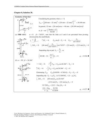
- 30. COSMOS: Complete Online Solutions Manual Organization System Vector Mechanics for Engineers: Statics and Dynamics, 8/e, Ferdinand P. Beer, E. Russell Johnston, Jr., Elliot R. Eisenberg, William E. Clausen, David Mazurek, Phillip J. Cornwell © 2007 The McGraw-Hill Companies. Chapter 8, Solution 30. Geometry of four-bar: Considering the geometry when 0,α = ( ) ( ) 1/ 2 2 2 60 mm 52 mm 36 mm 22 mm 58.549 mmCDL = − + + = In general, ( ) ( )52 mm 36 mm sin 60 mm 58.549 mm sinα β− = − so 1 36sin 8 sin 58.549 α β − + = (a) FBD ACE: 0 7.8533 ,α β= = ° note that the links at E and K are prevented from pivoting downward by the small blocks 0: sin 0, sin 7.8533 E y CD E CD F F F F FβΣ = − = = ° ( ) ( ) ( )0: 60 mm cos7.8533 32 mm 212 mm 0 sin 7.8533 E A E E F M F N Σ = ° − − = ° Impending slip on pad ,E E s F N µ = so 212 435.00 32 0E s F µ − − = 0.526sµ = (b) 30 , 26.364α β= ° = ° 3 0: cos26.364 0 2 x AB CD EF F F NΣ = − + ° − = 1 0: sin 26.364 0 2 y AB CD EF F F FΣ = − + ° − = Eliminating ( ), 0.89599 0.76916 0AB CD E EF F N F− − + = Impending slip ,E s EF Nµ= so ( )0.126834 1E s EF Nµ= − ( )0: 60 mm cos26.364A CDM FΣ = ° ( ) ( )212 mm 32 mm 0E s EN Nµ− − = ( )53.759 212 32 0CD s EF Nµ= − = 212 32 53.759 1 0.12634 s s µ µ − = − 0.277sµ =
- 31. COSMOS: Complete Online Solutions Manual Organization System Vector Mechanics for Engineers: Statics and Dynamics, 8/e, Ferdinand P. Beer, E. Russell Johnston, Jr., Elliot R. Eisenberg, William E. Clausen, David Mazurek, Phillip J. Cornwell © 2007 The McGraw-Hill Companies. Chapter 8, Solution 31. FBD ABD: FBD Pipe: FBD DF: ( ) ( )0: 15 mm 110 mm 0D A AΜ N FΣ = − = Impending slip: A SA AF Nµ= So 15 110 0SAµ− = 0.136364SAµ = 0.1364SAµ = 0: 0,x A xF F DΣ = − = x A SA AD F Nµ= = 60 mmr = 0: 0,y C A C AF N N N NΣ = − = = ( ) ( ) ( )0: 550 mm 15 mm 500 mm 0F C C xM F N DΣ = − − = Impending slip: C SC C SC AF N Nµ µ= = So, 550 15 500 0SC A A SA AN N Nµ µ− − = ( )550 15 500 0.136364SCµ = + 0.1512SCµ =
- 32. COSMOS: Complete Online Solutions Manual Organization System Vector Mechanics for Engineers: Statics and Dynamics, 8/e, Ferdinand P. Beer, E. Russell Johnston, Jr., Elliot R. Eisenberg, William E. Clausen, David Mazurek, Phillip J. Cornwell © 2007 The McGraw-Hill Companies. Chapter 8, Solution 32. FBD Plate: Assume reactions as shown, at ends of sleeves, For impending slip ,A s A B s BF N F Nµ µ= = 0: sin 0x s A s BF P N Nθ µ µΣ = − − = 2.5 sinA BN N P θ+ = 0: cos 0, cosy A B A BF N N P N N Pθ θΣ = − − = − = Solving: ( ) ( )2.5sin cos , 2.5sin cos 2 2 A B P P N Nθ θ θ θ= + = − (1) ( ) ( ) ( )0: 23.5 in. sin 16 in. 1 in. 0B A AM P N FθΣ = − + = ( ) ( ) ( )23.5 in. sin 16 in. 0.4 1 in. 2.5sin cos 0 2 P P θ θ θ − − + = (2) 4sin 7.8cos 0, 62.9θ θ θ− = = ° For 62.9 ,θ > ° the panel will be self locking, ∴motion for 62.9 .θ ≤ ° As θ decreases, BN will reverse direction at 2.5sin cos 0,θ θ− = (see equ. 1) or at 21.8 .θ = ° So for 21.8θ ≤ ° ( )0 : sin 0x s A BF P N Nθ µΣ = − + = 2.5 sinA BN N P θ+ = 0: cos 0, cosy A B A BF N N P N N Pθ θΣ = + − = + = 2.5sin cos , 21.8θ θ θ∴ = = ° So impending motion for 21.8 62.9θ° ≤ ≤ °
- 33. COSMOS: Complete Online Solutions Manual Organization System Vector Mechanics for Engineers: Statics and Dynamics, 8/e, Ferdinand P. Beer, E. Russell Johnston, Jr., Elliot R. Eisenberg, William E. Clausen, David Mazurek, Phillip J. Cornwell © 2007 The McGraw-Hill Companies. Chapter 8, Solution 33. FBD Plate: Assuming reactions as shown, at ends of sleeves, For impending slip ,A s A B s BF N F Fµ µ= = ( )0: sin 0x s A BF P N Nθ µΣ = − + = 2.5 sinA BN N P θ+ = (1) 0: cos 0, cosy A B A BF N N P N N Pθ θΣ = − − = − = (2) Solving: ( ) ( )2.5sin cos , 2.5sin cos 2 2 A B P P N Nθ θ θ θ= + = − Note that, for 21.8 ,θ < ° BN becomes negative, so we must change equ. 2 to cos ,A BN N P θ+ = ( 2′ ) but equ. (1) does not change. Solving (1) and ( 2′ ) gives cos 2.5 sin ,P Pθ θ= or 21.8 ,θ = ° so the lower limit for impending slip is 21.8 .θ = ° For 21.8 ,θ ≥ ° the forces are as shown, and ( ) ( ) ( )0: 23.5 in. sin cos 1 in. 16 in. 0B A AM P xP F Nθ θΣ = + + − = ( ) ( ) ( ) ( )23.5 in. sin cos 0.4 1 in. 16 in. 2.5sin cos 0 2 P P x Pθ θ θ θ + + − + = or ( )4sin 7.8 in. cos 0, tan 1.950 4 in. x xθ θ θ − − = = − (a) For 4 in.,x = tan 1.950,θ = 43.5 .θ = ° For 43.5θ > ° self locking ∴ impending motion for 21.8 43.5θ° ≤ ≤ ° (b) As x increases from 4 in., the upper bound for θ decreases, becoming ( )21.8 tan 0.4000θ° = when ( )( )4 in. 1.950 0.400 6.2 in.x = − = Thus max 6.20 in.x = at which θ must equal 21.8 .°
- 34. COSMOS: Complete Online Solutions Manual Organization System Vector Mechanics for Engineers: Statics and Dynamics, 8/e, Ferdinand P. Beer, E. Russell Johnston, Jr., Elliot R. Eisenberg, William E. Clausen, David Mazurek, Phillip J. Cornwell © 2007 The McGraw-Hill Companies. Chapter 8, Solution 34. FBD Collar: Impending motion down: Impending motion up: Stretch of spring cos a x AB a a θ = − = − ( )( ) 1 1.5 kN/m 0.5 m 1 cos cos s a F kx k a θ θ = = − = − ( ) 1 0.75 kN 1 cosθ = − 0: cos 0x sF N F θΣ = − = ( )( )cos 0.75 kN 1 cossN F θ θ= = − Impending slip: ( )( )( )0.4 0.75 kN 1 cossF Nµ θ= = − ( )( )0.3 kN 1 cosθ= − + down, – up 0: sin 0y sF F F WθΣ = ± − = ( )( ) ( )( )0.75 kN tan sin 0.3 kN 1 cos 0Wθ θ θ− ± − − = or ( ) ( ) ( )[ ]0.3 kN 2.5 tan sin 1 cosW θ θ θ= − ± − with 30 :θ = ° ( )up 0.01782 kN OKW = ( )down 0.0982 kN OKW = Equilibrium if 17.82 N 98.2 NW≤ ≤
- 35. COSMOS: Complete Online Solutions Manual Organization System Vector Mechanics for Engineers: Statics and Dynamics, 8/e, Ferdinand P. Beer, E. Russell Johnston, Jr., Elliot R. Eisenberg, William E. Clausen, David Mazurek, Phillip J. Cornwell © 2007 The McGraw-Hill Companies. Chapter 8, Solution 35. Geometry: FBD B: ( ) ( )1 m 0.5 m cos tan 0.5 m sinα θ α − = ( )tan 2 cos sinθ α α− = 30 60θ α= ° → = ° then ( ) 3 1 m cos30 m 2 ABL = ° = ( )0 kN 3 1 1.5 m m m 2 2 s ABF k L L = − = − ( )0.75 3 1 kN 549.04 NsF = − = 0: sin60 549.04 N 0xF F WΣ = + ° − = 549.04 N 2 W F = − 3 0: cos60 0, 2 yF N W N WΣ = − ° = = For impending slip upward, F is as shown and ,sF Nµ= so 3 549.04 N 0.40 , 2 2 W W− = min 648.61 NW = For impending slip downward, F is reversed, or ,sF Nµ= − so max 3 549.04 N 0.40 , 3575 N 2 2 W W W− = − = ( )2 9.81 m/s W m = so 66.1 kg 364 kgm≤ ≤
- 36. COSMOS: Complete Online Solutions Manual Organization System Vector Mechanics for Engineers: Statics and Dynamics, 8/e, Ferdinand P. Beer, E. Russell Johnston, Jr., Elliot R. Eisenberg, William E. Clausen, David Mazurek, Phillip J. Cornwell © 2007 The McGraw-Hill Companies. Chapter 8, Solution 36. FBD Collar: FBD AB: Note: BC is a two-force member, and for max,M slip will impend to the right. 0: cos 0, cosy BC BCF F N N Fθ θΣ = − = = Impending slip: coss s BCF N Fµ µ θ= = 0: sin 0x BCF F F PθΣ = − − = ( )sin cosBC sF Pθ µ θ− = ( )0: 2 cos 0A ABM M l F θΣ = − = 2 cos sin coss P M l θ θ µ θ = − max 2 tan s Pl M θ µ = − max max For tan , self locking For tan , 0 s s M M µ θ µ θ = = ∞ > <
- 37. COSMOS: Complete Online Solutions Manual Organization System Vector Mechanics for Engineers: Statics and Dynamics, 8/e, Ferdinand P. Beer, E. Russell Johnston, Jr., Elliot R. Eisenberg, William E. Clausen, David Mazurek, Phillip J. Cornwell © 2007 The McGraw-Hill Companies. Chapter 8, Solution 37. Geometry: FBD AB: 1 2 4 2cos 60 2 L L L L θ − + − = = ° For min a L slip will impend to right and reactions will be at ( )1 1 tan tan 0.35 19.2900s sφ µ− − = = = ° from normal. Note: AB is a three-force member ( ) ( ) ( )tan 60 tan 60s sCD a L aφ φ= + = − ° − ( ) ( ) ( )tan 79.29 tan 40.71a L a° = − ° 6.1449 1 L a = − 0.13996 a L = min 0.1400 a L =
- 38. COSMOS: Complete Online Solutions Manual Organization System Vector Mechanics for Engineers: Statics and Dynamics, 8/e, Ferdinand P. Beer, E. Russell Johnston, Jr., Elliot R. Eisenberg, William E. Clausen, David Mazurek, Phillip J. Cornwell © 2007 The McGraw-Hill Companies. Chapter 8, Solution 38. FBD A: FBD B: FBD A: FBD B: Note: Rod is a two force member. For impending slip the reactions are at angle ( )1 1 tan tan 0.40 21.801s sφ µ− − = = = ° Consider first impending slip to right 9 lb 3.8572 lb tan66.801 ABF = = ( ) ( )0: 3.8522 lb sin30 6 lb cos30 0y BF NΣ = − ° − ° = ( )7.1223 lb, 0.40 7.1223 lbB B s BN F Nµ= = = 2.8489 lbBF = ( ) ( )0: 2.8489 lb 3.8572 lb cos30 6 lb sin30 0xF PΣ = − + ° − ° − = min 2.508 lbP = − Next consider impending slip to left ( )9 lb tan66.801 21.000 lbABF = ° = ( ) ( )0: 21 lb sin30 6 lb cos30 0, 15.6959 lby B BF N NΣ = − ° − ° = = ( )0.4 15.6959 lb 6.2784 lbB s BF Nµ= = = ( ) ( )0: 6.2784 lb 21 lb cos30 6 lb sin30 0Fx PΣ = + ° − ° − = max 21.465 lbP = equilibrium for 2.51 lb 21.5 lbP− ≤ ≤
- 39. COSMOS: Complete Online Solutions Manual Organization System Vector Mechanics for Engineers: Statics and Dynamics, 8/e, Ferdinand P. Beer, E. Russell Johnston, Jr., Elliot R. Eisenberg, William E. Clausen, David Mazurek, Phillip J. Cornwell © 2007 The McGraw-Hill Companies. Chapter 8, Solution 39. FBD AB: ( )2 2 0: 8 in 4 in 0A AM N MΣ = + − = ( )( )12 lb ft 12 in./ft 16.100 lb 8.9443 in. N ⋅ = = Impending motion: ( )0.3 16.100 lb 4.83 lbsF Nµ= = = Note: For max MC, need F in direction shown; see FBD BC. FBD BC + collar: ( ) ( ) ( ) 1 2 2 0: 17 in. 8 in. 13 in. 0 5 5 5 C CM M N N FΣ = − − − = or ( ) ( ) ( ) 17 in. 16 in. 26 in. 16.100 lb 16.100 lb 4.830 lb 293.77 lb in. 5 5 5 CM = + + = ⋅ ( )max 24.5 lb ftC = ⋅M
- 40. COSMOS: Complete Online Solutions Manual Organization System Vector Mechanics for Engineers: Statics and Dynamics, 8/e, Ferdinand P. Beer, E. Russell Johnston, Jr., Elliot R. Eisenberg, William E. Clausen, David Mazurek, Phillip J. Cornwell © 2007 The McGraw-Hill Companies. Chapter 8, Solution 40. FBD yoke: FBD wheel and slider: 0: 0, 8 lbxF P N N PΣ = − = = = For impending slip, ( )125 8 lbsF Nµ= = 2 lbF = For max,M F on yoke is down as shown For min,M F on yoke is up. (a) For maxM the 2 lb force is up as shown. ( ) ( ) ( ) ( )0: 3 in. sin 65 8 lb 3 in. cos65 2 lb 0B BM M Σ = − ° − ° = max 24.3 lb in.B = ⋅M (b) For minM the 2 lb force is reversed, and ( ) ( ) ( ) ( )0: 3in. sin65 8 lb 3 in. cos65 2 lb 0B BM M Σ = − ° + ° = min 19.22 lb in.B = ⋅M
- 41. COSMOS: Complete Online Solutions Manual Organization System Vector Mechanics for Engineers: Statics and Dynamics, 8/e, Ferdinand P. Beer, E. Russell Johnston, Jr., Elliot R. Eisenberg, William E. Clausen, David Mazurek, Phillip J. Cornwell © 2007 The McGraw-Hill Companies. Chapter 8, Solution 41. FBD Rod: FBD Cylinder: ( ) ( )( )10: 20 in. 12.5 in. 12 lb 0AM NΣ = − = 1 7.5 lb.N = 2 20: 7.5 lb 36 lb 0, 43.5 lbyF N NΣ = − − = = since 1 2µ µ= and 1 2,N N< slip will impend at top of cylinder first, so 1 1sF Nµ= . ( )1 0.35 7.5 lb 2.625 lbF = = ( ) ( )( )0: 4.25 in. 12.5 in. 2.625 lb 0, 7.7206 lbDM P PΣ = − = = max 7.72 lbP = To check slip analysis above, 20: 36 lb 7.5 lb 0yF NΣ = − − = 2 43.5 lbN = ( )2max 2 0.35 43.5 lb 15.225 lbsF Nµ= = = 1 2 20: 0, 7.72 lb 2.625 lb 0xF P F F FΣ = − − = − − = 2 max5.095 lb ,F F= < OK
- 42. COSMOS: Complete Online Solutions Manual Organization System Vector Mechanics for Engineers: Statics and Dynamics, 8/e, Ferdinand P. Beer, E. Russell Johnston, Jr., Elliot R. Eisenberg, William E. Clausen, David Mazurek, Phillip J. Cornwell © 2007 The McGraw-Hill Companies. Chapter 8, Solution 42. FBD pulley: FBD block A: ( )( )2 2.4 kg 9.81 m/s 23.544 NAW = = FBD block C: Note that ( )1 1 tan tan 0.5 26.565 30 ,SA SAφ µ− − = = = ° < ° Cable is needed to keep A from sliding downward. 0: 2 0, , 2 2 B y B B W F T W T W TΣ = − = = = (1) (a) For minimum ,BW there will be impending slip of block A downward, and A SA AF Nµ= as shown. 0: cos30 0, cos30A A A AFy N W N W′Σ = − ° = = ° 23.544 Ncos30 20.390 N= ° = ( )( )0.50 20.390 N 10.195 NAF = = 0: sin30 0x A AF T W F′Σ = − ° + = ( )23.544 N sin30 10.195 N 1.577 NT = ° − = From (1) ( )2 3.154 N 2 3.154 N, 0.322 kg, 9.81 m/s B BW T m= = = = min 322 gBm = 0: 0, 58.86 Ny C C CF N W NΣ = − = = ( )max 0.30 58.86 N 17.658 NC SC CF Nµ= = = Since max1.577 N ,CT F= < block B doesn’t slip and above answer for minBm is correct.
- 43. COSMOS: Complete Online Solutions Manual Organization System Vector Mechanics for Engineers: Statics and Dynamics, 8/e, Ferdinand P. Beer, E. Russell Johnston, Jr., Elliot R. Eisenberg, William E. Clausen, David Mazurek, Phillip J. Cornwell © 2007 The McGraw-Hill Companies. (b) For maxBm assume impending slip of block C to left, maxCF F= max0: 0, 17.658 Nx C C CF T F T F FΣ = − + = = = = From (1) 2 35.316 N 2 35.316 N, 3.6 kg 9.81 m/s B B B W W T m g = = = = = From FBD block A, 0: sin30 0, sin30x A A A AF T W F F W TΣ = − ° + = = ° − ( ) max23.544 N sin30 17.658 N 5.886, 10.195 NA AF F= ° − = − = Since max,A AF F< A does not slip max 3.6 kgBM =
- 44. COSMOS: Complete Online Solutions Manual Organization System Vector Mechanics for Engineers: Statics and Dynamics, 8/e, Ferdinand P. Beer, E. Russell Johnston, Jr., Elliot R. Eisenberg, William E. Clausen, David Mazurek, Phillip J. Cornwell © 2007 The McGraw-Hill Companies. Chapter 8, Solution 43. FBD A: FBD B and C: FBD B: For impending motion A must start up and C down the incline. Since the normal force between A and B is less than that between B and C, and the friction coefficients are the same, maxF will be reached first between A and B, and B and C will stay together. ( )1 10: 4 lb cos30 0, 2 3 lbyF N NΣ = − ° = = Impending slip: 1 1 2 3 lbs sF Nµ µ= = ( )0: 4 lb sin30 2 3 lb 0x sF T µΣ = − ° − = ( )2 1 3 lbsT µ= + (1) ( )20: 2 3 lb 3 lb 8 lb cos30 0yF NΣ = − − + ° = 2 15 3 lb 2 N = Impending slip: 2 2 15 3 lb 2 s sF Nµ µ= = ( ) 15 0: 2 3 3 lb 3 8 lbsin30 0 2 µ Σ = + + − + ° = x sF T 11 19 3 lb 2 2 sT µ = − (2) Equating (1) and (2): ( )4 1 3 lb 11 19 3s sµ µ+ = − min23 3 7, 0.1757s sµ µ= = To check slip reasoning above: ( )3 3 7 0: 2 3 lb 3 lb cos30 0, 3 lb 2 yF N NΣ = − − ° = = 3max 3 7 3 2 s sF Nµ µ= = ( ) 30: 3 lb sin30 2 3 lb 0x sF FµΣ = − ° + − = ( )3 3 2 3 0.1757 lb lb 0.891 lb 2 F = − = − 3 3max,F F< OK
- 45. COSMOS: Complete Online Solutions Manual Organization System Vector Mechanics for Engineers: Statics and Dynamics, 8/e, Ferdinand P. Beer, E. Russell Johnston, Jr., Elliot R. Eisenberg, William E. Clausen, David Mazurek, Phillip J. Cornwell © 2007 The McGraw-Hill Companies. Chapter 8, Solution 44. FBD rod: ( ) 3 in. 0: 4.5 in. cos 0 cos A BM N Wθ θ Σ = − = or ( )2 1.5cosBN Wθ= Impending motion: ( )2 1.5 cosB s B sF N Wµ µ θ= = ( )2 0.3cos Wθ= 0: sin cos 0x A B BF N N Fθ θΣ = − + = or ( ) ( )2 1.5cos sin 0.2cosAN Wθ θ θ= − Impending motion: A s AF Nµ= ( ) ( )2 0.3cos sin 0.2cosWθ θ θ= − 0: cos sin 0y A B BF F N F Wθ θΣ = + + − = or ( )3 2 1 1.5cos 0.3cos sinAF W θ θ θ= − − Equating FA’s ( )2 3 2 0.3cos sin 0.2cos 1 1.5cos 0.3cos sinθ θ θ θ θ θ− = − − 2 3 0.6cos sin 1.44cos 1θ θ θ+ = Solving numerically 35.8θ = °
- 46. COSMOS: Complete Online Solutions Manual Organization System Vector Mechanics for Engineers: Statics and Dynamics, 8/e, Ferdinand P. Beer, E. Russell Johnston, Jr., Elliot R. Eisenberg, William E. Clausen, David Mazurek, Phillip J. Cornwell © 2007 The McGraw-Hill Companies. Chapter 8, Solution 45. FBD pin A: FBD B: FBD C: 12 3 0: 0 13 5 x AB ACF F FΣ = − = 5 4 0: 0 13 5 y AB ACF F F PΣ = + − = Solving: 13 20 , 21 21 AB ACF P F P= = 12 13 12 0: 0, 13 21 21 x B BF N P N PΣ = − ⋅ = = For minP slip of B impends down, so 11 20 B s B BF N Nµ= = min 11 12 5 13 0: 18 lb 0, 236.25 lb 20 21 13 21 yF P P PΣ = ⋅ − ⋅ − = = (For 236.25 lb,P < A will slip down) 4 20 16 0: 80 lb 0, 80 lb 5 21 21 y C CF N P N PΣ = − − ⋅ = = + For maxP slip of C impends to right, C s CF Nµ= or 11 16 44 80 lb 44 lb 20 21 105 CF P P = + = + 3 20 0: 0, 5 21 x CF P FΣ = ⋅ − = 12 44 44 lb 21 105 P P= + max 288.75 lbP = ∴ equilibrium 236 289P≤ ≤
- 47. COSMOS: Complete Online Solutions Manual Organization System Vector Mechanics for Engineers: Statics and Dynamics, 8/e, Ferdinand P. Beer, E. Russell Johnston, Jr., Elliot R. Eisenberg, William E. Clausen, David Mazurek, Phillip J. Cornwell © 2007 The McGraw-Hill Companies. Chapter 8, Solution 46. ( )1 1 tan tan 0.4 21.801 ,s sφ µ− − = = = ° slip impends at wedge/block wedge/wedge and block/incline FBD Block: 2 530 lb sin 41.801 sin 46.398 R = ° ° 2 487.84 lbR = FBD Wedge: 487.84 lb sin51.602 sin 60.199 P = ° ° 441 lbP =
- 48. COSMOS: Complete Online Solutions Manual Organization System Vector Mechanics for Engineers: Statics and Dynamics, 8/e, Ferdinand P. Beer, E. Russell Johnston, Jr., Elliot R. Eisenberg, William E. Clausen, David Mazurek, Phillip J. Cornwell © 2007 The McGraw-Hill Companies. Chapter 8, Solution 47. ( )1 1 tan tan 0.40 21.801 ,s sφ µ− − = = = ° and slip impends at wedge/lower block, wedge/wedge, and upper block/incline interfaces. FBD Upper block and wedge: 2 530 lb sin 41.801 sin38.398 R = ° ° 2 568.76 lbR = FBD Lower wedge: 568.76 lb sin51.602 sin68.199 P = ° ° 480 lbP =
- 49. COSMOS: Complete Online Solutions Manual Organization System Vector Mechanics for Engineers: Statics and Dynamics, 8/e, Ferdinand P. Beer, E. Russell Johnston, Jr., Elliot R. Eisenberg, William E. Clausen, David Mazurek, Phillip J. Cornwell © 2007 The McGraw-Hill Companies. Chapter 8, Solution 48. ( )( )2 18 kg 9.81 m/s 176.58 NDW = = ( )( )3.5 kN/m 0.1 m 0.35 kN = 350 NsF kx= = = ( )1 1 tan tan 0.25 14.0362s sφ µ− − = = = ° FBD Lever: ( )( ) ( )( )0: 0.3 m 350 N 0.4 m 176.58 NCMΣ = − ( )0.525 m cos4.0362AR− ° ( )0.05 m sin 4.0362 0AR+ ° = 66.070 NAR = ( )0: 66.07 N sin 4.0362 0,x xF CΣ = ° + = 4.65 NxC = − ( )0: 66.07 N cos4.0362 350 N 176.58 N = 0yFΣ = ° − − FBD Wedge: 66.070 N sin18.072 sin75.964 P = ° ° 21.1 lbP = (a) 21.1 lbP = (b) 4.65 Nx =C 461 Ny =C
- 50. COSMOS: Complete Online Solutions Manual Organization System Vector Mechanics for Engineers: Statics and Dynamics, 8/e, Ferdinand P. Beer, E. Russell Johnston, Jr., Elliot R. Eisenberg, William E. Clausen, David Mazurek, Phillip J. Cornwell © 2007 The McGraw-Hill Companies. Chapter 8, Solution 49. ( )( )2 18 kg 9.81 m/s 176.58 NDW = = ( )( )3.5 kN/m 0.1 m 0.35 kN = 350 NsF kx= = = ( )1 1 tan tan 0.25 14.0362s sφ µ− − = = = ° FBD Lever: ( )( ) ( )( )0: 0.3 m 350 N 0.4 m 176.58 NCMΣ = − ( )0.525 m cos24.036AR− ° ( )0.05 m sin 24.036 0AR− ° = 68.758 NAR = ( )0: 68.758 N sin 24.036 0,x xF CΣ = − ° = 28.0 NxC = ( )0: 350 N 176.58 N + 68.758 N cos24.036 0y yF CΣ = − − ° = 464 NyC = FBD Wedge: 68.758 N sin38.072 sin75.964 P = ° ° (a) 43.7 NP = (b) 28.0 Nx =C 464 Ny =C
- 51. COSMOS: Complete Online Solutions Manual Organization System Vector Mechanics for Engineers: Statics and Dynamics, 8/e, Ferdinand P. Beer, E. Russell Johnston, Jr., Elliot R. Eisenberg, William E. Clausen, David Mazurek, Phillip J. Cornwell © 2007 The McGraw-Hill Companies. Chapter 8, Solution 50. For steel/steel contact, ( )1 1 1 1 tan tan 0.3 16.6992s sφ µ− − = = = ° For steel/concrete interface, ( )2 2 1 1 tan tan 0.6 30.964s sφ µ− − = = = ° FBD Plate CD: 0: 90 kN 0,yF NΣ = − = 90 kNF = Impending slip: ( )1 0.3 90 kN 27 kNsF Nµ= = = 0: 0,xF F QΣ = − = 27 kNQ F= = FBD Top wedge assuming impending slip between wedges: 0: cos26.699 90 kN = 0,y wF RΣ = ° − 100.74 kNwR = ( )0: 27 kN 100.74 kN sin 26.699 0xF PΣ = − − ° = 72.265 kN,P = (a) 72.3 kN=P (b) 27.0 kN=Q To check above assumption; note that bottom wedge is a two-force member so the reaction of the floor on that wedge is Rw, at 26.699° from the vertical. This is less than 2 30.964 ,sφ = ° so the bottom wedge doesn’t slip on the concrete.
- 52. COSMOS: Complete Online Solutions Manual Organization System Vector Mechanics for Engineers: Statics and Dynamics, 8/e, Ferdinand P. Beer, E. Russell Johnston, Jr., Elliot R. Eisenberg, William E. Clausen, David Mazurek, Phillip J. Cornwell © 2007 The McGraw-Hill Companies. Chapter 8, Solution 51. For steel/steel contact, ( )1 1 1 1 tan tan 0.30 16.6992s sφ µ− − = = = ° For steel/concrete contact, ( )2 2 1 1 tan tan 0.60 30.964s sφ µ− − = = = ° FBD Plate CD and top wedge: 90 kN tan 26.6992 = 45.264 kNQ = ° 90 kN 100.741 kN cos26.6992 wR = = ° FBD Bottom wedge: slip impends at both surfaces 100.714 kN sin57.663 sin59.036 P = ° ° (a) 99.3 kN=P (b) 45.3 kN=Q
- 53. COSMOS: Complete Online Solutions Manual Organization System Vector Mechanics for Engineers: Statics and Dynamics, 8/e, Ferdinand P. Beer, E. Russell Johnston, Jr., Elliot R. Eisenberg, William E. Clausen, David Mazurek, Phillip J. Cornwell © 2007 The McGraw-Hill Companies. Chapter 8, Solution 52. FBD Wedge: FBD Block C: ( )1 1 tan tan 0.4 21.801s sφ µ− − = = = ° By symmetry B CR R= ( )0: 2 sin 29.801 0,y CF R PΣ = ° − = 0.9940 CP R= 175 lb , sin 41.801 sin18.397 lb CR = ° 367.3 lbP = (a) 367 lbP = b) Note: That increasing friction between B and the incline will mean that block B will not slip, but the above calculations will not change. (b) 367 lbP =
- 54. COSMOS: Complete Online Solutions Manual Organization System Vector Mechanics for Engineers: Statics and Dynamics, 8/e, Ferdinand P. Beer, E. Russell Johnston, Jr., Elliot R. Eisenberg, William E. Clausen, David Mazurek, Phillip J. Cornwell © 2007 The McGraw-Hill Companies. Chapter 8, Solution 53. FBD Block C: ( )1 1 tan tan 0.4 21.8014s sφ µ− − = = = ° 0: 0x ACx CFxF R RΣ = − = 0: 175 lb = 0y CFy ACyF R RΣ = − − so 175 lbCFy ACy CFx ACx ACx R R R R R − = ( ) ( )cot 20 cot 32.2 0φ° + − ° > 12.2 21.8sφ φ< ° < = ° so block C does not slip (or impend) FBD Block B: (a) ( )1 1 tan tan 0.4 21.8014B Bφ µ− − = = = ° 175 lb , sin 41.8014 sin 46.3972 BR = ° ° 161.083 lbBR = (b) ( )1 1 tan tan 0.6 30.9638B Bφ µ− − = = = ° 175 lb , sin50.9638 sin37.2330 BR = ° ° 224.65 lbBR = FBD Wedge: , sin59.6028 sin52.1986 BP R = ° ° 1.09163 BP R= (a) 161.083 lb,BR = 175.8 lbP = (b) 224.65 lb,BR = 245 lbP =
- 55. COSMOS: Complete Online Solutions Manual Organization System Vector Mechanics for Engineers: Statics and Dynamics, 8/e, Ferdinand P. Beer, E. Russell Johnston, Jr., Elliot R. Eisenberg, William E. Clausen, David Mazurek, Phillip J. Cornwell © 2007 The McGraw-Hill Companies. Chapter 8, Solution 54. Since vertical forces are equal and ground wood,s sµ µ> assume no impending motion of board. Then there will be impending slip at all wood/wood contacts, ( )1 1 tan tan 0.35 19.2900s sφ µ− − = = = ° FBD Top wedge: 1 8 kN 8.4758 kN cos19.29 R = = ° 1 sin52.710 cos56.580 R P = ° ° 8.892 kNP = To check assumption, consider FBD wedges + board: ( )1 1 8 kN = 0.35 8 kN 2.8 kNF µ= = 0: 8 kN 0,y GF NΣ = − = 8 kNGN = ( )( )max 0.6 8 kN 4.8 kNG G GF Nµ= = = 10: 0,x GF F FΣ = − = 1 2.8 kNGF F= = max,G GF F< OK 8.89 kNP∴ =
- 56. COSMOS: Complete Online Solutions Manual Organization System Vector Mechanics for Engineers: Statics and Dynamics, 8/e, Ferdinand P. Beer, E. Russell Johnston, Jr., Elliot R. Eisenberg, William E. Clausen, David Mazurek, Phillip J. Cornwell © 2007 The McGraw-Hill Companies. Chapter 8, Solution 55. Assume no impending motion of board on ground. Then there will be impending slip at all wood/wood interfaces. FBD Top wedge: Wedge is a two-force member so 2 1= −R R and ( )1 1 2 2tan 2tan 0.35s sθ φ µ− − = = = 38.6θ = ° To check assumption, consider FBD wedges + board: ( )1 18 kN = 0.35 8 kN 2.8 kNF µ= = 0: 8 kN 0,y GF NΣ = − = 8 kNGN = ( )( )max 0.6 8 kN 4.8 kNG G GF Nµ= = = 10: 0,x GF F FΣ = − = 1 2.8 kNGF F= = max,G GF F< OK 8.89 kNP∴ =
- 57. COSMOS: Complete Online Solutions Manual Organization System Vector Mechanics for Engineers: Statics and Dynamics, 8/e, Ferdinand P. Beer, E. Russell Johnston, Jr., Elliot R. Eisenberg, William E. Clausen, David Mazurek, Phillip J. Cornwell © 2007 The McGraw-Hill Companies. Chapter 8, Solution 56. FBD Cylinder: Slip impends at B ( )1 tan 0.35 19.2900SCφ − = = ° ( ) 4 0: cos 12 19.29 0 3 A C r M r R W π Σ = ° + ° − = 0.49665,CR = 124.163 lbW = FBD Wedge: ( )1 1 tan tan 0.50 26.565SF SFφ µ− − = = = ° 124.163 lb sin58.855 sin63.435 P = ° ° 117.5 lbP =
- 58. COSMOS: Complete Online Solutions Manual Organization System Vector Mechanics for Engineers: Statics and Dynamics, 8/e, Ferdinand P. Beer, E. Russell Johnston, Jr., Elliot R. Eisenberg, William E. Clausen, David Mazurek, Phillip J. Cornwell © 2007 The McGraw-Hill Companies. Chapter 8, Solution 57. FBD tip of screwdriver: ( )1 1 tan tan 0.12 6.8428s sφ µ− − = = = ° by symmetry 1 2R R= ( )10: 2 sin 6.8428 8 3.5 N 0yF RΣ = ° + ° − = 1 2 6.8315 NR R= = If P is removed quickly, the vertical components of R1 and R2 vanish, leaving the horizontal components ( )1 2 6.8315 N cos14.8428H H= = ° 6.6035 N= Side forces = 6.60 N This is only instantaneous, since 8 ,sφ° > so the screwdriver will be forced out.
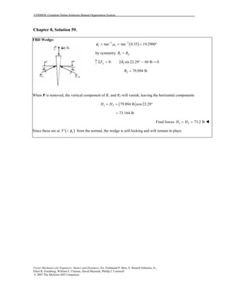
- 59. COSMOS: Complete Online Solutions Manual Organization System Vector Mechanics for Engineers: Statics and Dynamics, 8/e, Ferdinand P. Beer, E. Russell Johnston, Jr., Elliot R. Eisenberg, William E. Clausen, David Mazurek, Phillip J. Cornwell © 2007 The McGraw-Hill Companies. Chapter 8, Solution 58. As the plates are moved, the angle θ will decrease. (a) 1 1 tan tan 0.2 11.31 .s sφ µ− − = = = ° As θ decreases, the minimum angle at the contact approaches 12.5 11.31 ,sφ° > = ° so the wedge will slide up and out from the slot. (b) 1 1 tan tan 0.3 16.70 .s sφ µ− − = = = ° As θ decreases, the angle at one contact reaches 16.7 .° (At this time the angle at the other contact is 25 16.7 8.3 )sφ° − ° = ° < The wedge binds in the slot.
- 60. COSMOS: Complete Online Solutions Manual Organization System Vector Mechanics for Engineers: Statics and Dynamics, 8/e, Ferdinand P. Beer, E. Russell Johnston, Jr., Elliot R. Eisenberg, William E. Clausen, David Mazurek, Phillip J. Cornwell © 2007 The McGraw-Hill Companies. Chapter 8, Solution 59. FBD Wedge: ( )1 1 tan tan 0.35 19.2900s sφ µ− − = = = ° by symmetry 1 2R R= 10: 2 sin 22.29 60 lb 0yF RΣ = ° − = 2 79.094 lbR = When P is removed, the vertical component of R1 and R2 will vanish, leaving the horizontal components ( )1 2 79.094 lb cos22.29H H= = ° 73.184 lb= Final forces 1 2 73.2 lbH H= = Since these are at ( )3 sφ° < from the normal, the wedge is self-locking and will remain in place.
- 61. COSMOS: Complete Online Solutions Manual Organization System Vector Mechanics for Engineers: Statics and Dynamics, 8/e, Ferdinand P. Beer, E. Russell Johnston, Jr., Elliot R. Eisenberg, William E. Clausen, David Mazurek, Phillip J. Cornwell © 2007 The McGraw-Hill Companies. Chapter 8, Solution 60. FBD Cylinder: note 3 tan30 r d r= = FBD Wedge: ( )( )2 80 kg 9.81 m/s 784.8 NW = = 0: 0,G A B A BM F F F FΣ = − = = (1) 0: 0, 3 D B A A B W M dN dN rW N NΣ = − + = = + (2) so max max,A B A BN N F F> > ∴ slip impends first at B. 0.25B s B BF N Nµ= = ( ) ( ) ( )( )0: cos30 sin30 1 sin30 0.25 0A B BM r N r W r NΣ = ° − ° − + ° = 1.01828 799.15 NBN W= = 0.25 199.786 NB BF N= = From (2) above, 784.8 N 799.15 N + 1252.25 N 3 AN = = From (1), 199.786 NA BF F= = ( )0: 1252.25 N cos10 199.786 N sin10 0y CF NΣ = − ° + ° = 1198.53 NCN = Impending slip ( )0.25 1198.53 N 299.63 NC s CF Nµ= = = ( )0: 299.63 N 199.786 N cos10xF PΣ = − − ° ( )1252.25 N sin10 0− ° = 714 N=P 20.0°
- 62. COSMOS: Complete Online Solutions Manual Organization System Vector Mechanics for Engineers: Statics and Dynamics, 8/e, Ferdinand P. Beer, E. Russell Johnston, Jr., Elliot R. Eisenberg, William E. Clausen, David Mazurek, Phillip J. Cornwell © 2007 The McGraw-Hill Companies. Chapter 8, Solution 61. FBD Cylinder: ( )( )2 80 kg 9.81 m/s 784.8 NW = = For impending slip at B, 0.30B sB B BF N Nµ= = ( ) ( )( )0: cos30 1 sin30 0.30A B BM r N r NΣ = ° − + ° sin30 0r W− ° = 1.20185 943.21 NBN W= = 0.30 0.36055B BF N W= = ( )0: 0, 0.36055G A B A BM r F F F F WΣ = − = = = 0: sin30 cos30 0x A A BF N F NΣ = ° + ° − = ( )0.36055 cos30 1.20185 sin30 A W W N − ° + = ° 1.77920AN W= For minimum ,Aµ slip impends at A, so min 0.36055 0.2026 1.77920 A A A F W N W µ = = = min 0.203Aµ =
- 63. COSMOS: Complete Online Solutions Manual Organization System Vector Mechanics for Engineers: Statics and Dynamics, 8/e, Ferdinand P. Beer, E. Russell Johnston, Jr., Elliot R. Eisenberg, William E. Clausen, David Mazurek, Phillip J. Cornwell © 2007 The McGraw-Hill Companies. Chapter 8, Solution 62. FBD plank + wedge: ( ) ( )( )( )0: 8 ft 1.5 ft 48 lb/ft 3 ftA BM NΣ = − ( ) ( )( ) 1 2 ft 48 lb/ft 3 ft 2 − ( )( ) 5 1 3 ft 96 lb/ft 5 ft 0 3 2 − + = 185 lbBN = ( ) 48 96 0: 185 lb lb/ft 3ft 2 y WF N + Σ = + − ( )( ) 1 96 lb/ft 5 ft 0 2 + = 271 lbWN = Since ,W BN N> and all sµ are equal, assume slip impends at B and between wedge and floor, and not at A. Then ( )0.45 271 lb 121.95 lbW s WF Nµ= = = ( )0.45 185 lb 83.25 lbB s BF Nµ= = = 0: 121.95 lb 83.25 lb 0, 205.20 lbxF P PΣ = − − = = Check Wedge for assumption 0: 271 lb cos 0y AF R θΣ = − = 0: 205.2 lb 121.95 lb sin 0x AF R θΣ = − − = so tan 0.3072 tan9sθ µ 83.25 = = < + ° 271 so no slip here ∴ (a) 205 lb=P (b) impending slip at B
- 64. COSMOS: Complete Online Solutions Manual Organization System Vector Mechanics for Engineers: Statics and Dynamics, 8/e, Ferdinand P. Beer, E. Russell Johnston, Jr., Elliot R. Eisenberg, William E. Clausen, David Mazurek, Phillip J. Cornwell © 2007 The McGraw-Hill Companies. Chapter 8, Solution 63. FBD plank + wedge: ( ) ( )( )( )0: 8 ft 1.5 ft 48 lb/ft 3 ftA BM NΣ = − ( ) ( )( ) 1 2 ft 48 lb/ft 3 ft 2 − ( )( ) 5 3 ft 96 lb/ft 5 ft 0 3 − + = 185 lbWN = ( ) 48 96 0: 185 lb lb/ft 3ft 2 y AF N + Σ = + − ( )( ) 1 96 lb/ft 5 ft 0 2 − = 271 lbAN = Since ,A WN N> and all sµ are equal, assume impending slip at top and bottom of wedge and not at A. Then ( )0.45 185 NW s WF Nµ= = 83.25 lbWF = FBD Wedge: ( )1 1 tan tan 0.45 24.228s sφ µ− − = = = ° ( )0: 185 lb cos 24.228 9 0y BF RΣ = − ° + ° = 221.16 lbBR = ( )0: 221.16 lb sin33.228 83.25 lb 0xF PΣ = ° + − = 204.44 lbP = Check assumption using plank/wedge FBD 0: 0, 204.44 lb 83.25 lb 121.19 lbx A W AF F F P FΣ = + − = = − = ( )max 0.45 271 lb 121.95 lbA s AF Nµ= = = max,A AF F< OK ∴ (a) 204 lb=P (b) no impending slip at A
- 65. COSMOS: Complete Online Solutions Manual Organization System Vector Mechanics for Engineers: Statics and Dynamics, 8/e, Ferdinand P. Beer, E. Russell Johnston, Jr., Elliot R. Eisenberg, William E. Clausen, David Mazurek, Phillip J. Cornwell © 2007 The McGraw-Hill Companies. Chapter 8, Solution 64. ( )( ) ( )( )2 2 10 kg 9.81 m/s 98.1 N, 50 kg 9.81 m/s 490.5 NA BW W= = = = Slip must impend at all surfaces simultaneously, sF Nµ= FBD I: A + B 0: 150 N 98.1 N 490.5 N 0, 738.6 Ny B BF N NΣ = − − − = = impending slip: ( )738.6 NB s B sF Nµ µ= = ( )0: 0, 738.6 Nx A B A sF N F N µΣ = − = = FBD II: A ( ) ( )0: 738.6 N sin 20 150 N + 98.1 N cos20 0y AB sF F µ′ Σ = + ° − ° = ( )233.14 252.62 NAB sF µ = − ( ) ( )0: 738.6 N cos20 150 N + 98.1 N sin 20 0x s ABF Nµ′ Σ = ° − ° − = ( )84.855 694.06 NAB sN µ = + 233.14 252.62 84.855 694.06 AB s s AB s F N µ µ µ − = = + 2 0.48623 0.33591 0s sµ µ= − = 0.24312 0.62850sµ = − ± Positive root 0.385sµ =
- 66. COSMOS: Complete Online Solutions Manual Organization System Vector Mechanics for Engineers: Statics and Dynamics, 8/e, Ferdinand P. Beer, E. Russell Johnston, Jr., Elliot R. Eisenberg, William E. Clausen, David Mazurek, Phillip J. Cornwell © 2007 The McGraw-Hill Companies. Chapter 8, Solution 65. ( )( ) ( )( )2 2 10 kg 9.81 m/s 98.1 N, 50 kg 9.81 m/s 490.5 NA BW W= = = = Slip impends at all surfaces simultaneously FBD I: A + B 0: 0,x A B A B s BF N F N F NµΣ = − = = = (1) ( )0: 150 N + 98.1 N + 490.5 N 0y A BF F NΣ = − + = 738.6 Ns A BN Nµ + = (2) Solving (1) and (2) 2 2 738.6 N 738.6 , N 1 1 s B B s s N F µ µ µ = = + + FBD II: B ( )0: 490.5 N cos70 cos70 sin70 0x AB B BF N N F′Σ = + ° − ° − ° = ( ) ( )2 738.6 N cos70 sin 70 490.5 N cos70 1 AB s s N µ µ = ° + ° − ° + (1) ( )0: 490.5 N sin 70 sin70 cos70 0y AB B BF F N F′Σ = − − ° + ° − ° = ( ) ( )2 738.6 N sin 70 cos70 490.5 N sin70 0 1 AB s s F µ µ = ° − ° − ° = + Setting ,AB s ABF Nµ= 3 2 6.8847 2.0116 1.38970 0s s sµ µ µ− − + = Solving numerically, 0.586, 0.332, 7.14sµ = − Physically meaningful solution: 0.332sµ =
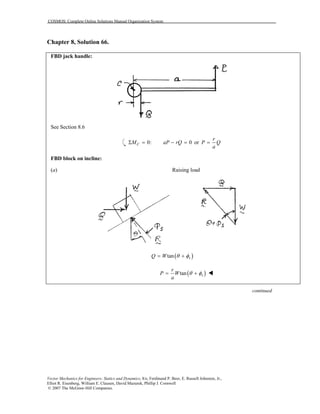
- 67. COSMOS: Complete Online Solutions Manual Organization System Vector Mechanics for Engineers: Statics and Dynamics, 8/e, Ferdinand P. Beer, E. Russell Johnston, Jr., Elliot R. Eisenberg, William E. Clausen, David Mazurek, Phillip J. Cornwell © 2007 The McGraw-Hill Companies. Chapter 8, Solution 66. FBD jack handle: See Section 8.6 0: 0CM aP rQΣ = − = or r P Q a = FBD block on incline: (a) Raising load ( )tan sQ W θ φ= + ( )tan s r P W a θ φ= + continued
- 68. COSMOS: Complete Online Solutions Manual Organization System Vector Mechanics for Engineers: Statics and Dynamics, 8/e, Ferdinand P. Beer, E. Russell Johnston, Jr., Elliot R. Eisenberg, William E. Clausen, David Mazurek, Phillip J. Cornwell © 2007 The McGraw-Hill Companies. PROBLEM 8.66 CONTINUED (b) Lowering load if screw is self-locking (i.e.: if sφ θ> ) ( )tan sQ W φ θ= − ( )tan s r P W a φ θ= − (c) Holding load is screw is not self-locking ( )i.e: if sφ θ< ( )tan sQ W θ φ= − ( )tan s r P W a θ φ= −
- 69. COSMOS: Complete Online Solutions Manual Organization System Vector Mechanics for Engineers: Statics and Dynamics, 8/e, Ferdinand P. Beer, E. Russell Johnston, Jr., Elliot R. Eisenberg, William E. Clausen, David Mazurek, Phillip J. Cornwell © 2007 The McGraw-Hill Companies. Chapter 8, Solution 67. FBD large gear: ( )0: 12 in. 7.2 kip in. 0, 0.600 kipsCM W WΣ = − ⋅ = = 600 lb= Block on incline: ( ) 1 0.375 in. tan 2.2785 2 1.5 in. θ π − = = ° 1 1 tan tan 0.12 6.8428s sφ µ− − = = = ° ( )tan sQ W θ φ= + ( )600 lb tan9.1213 96.333 lb= ° = FBD worm gear: 1.5 in.r = ( )( )0: 1.5 in. 96.333 lb 0BM MΣ = − = 144.5 lb in.M = ⋅
- 70. COSMOS: Complete Online Solutions Manual Organization System Vector Mechanics for Engineers: Statics and Dynamics, 8/e, Ferdinand P. Beer, E. Russell Johnston, Jr., Elliot R. Eisenberg, William E. Clausen, David Mazurek, Phillip J. Cornwell © 2007 The McGraw-Hill Companies. Chapter 8, Solution 68. FBD large gear: ( )0: 12 in. 7.2 kip in. 0CM WΣ = − ⋅ = 0.600 kips 600 lbW = = Block on incline: ( ) 1 0.375 in. tan 2.2785 2 1.5 in. θ π − = = ° 1 1 tan tan 0.12 6.8428s sφ µ− − = = = ° ( )tan sQ W φ θ= − ( )600 lb tan 4.5643 47.898 lb= ° = FBD worm gear: 1.5 in.r = ( )( )0: 1.5 in. 47.898 lb 0BM MΣ = − = 71.8 lb in.M = ⋅
- 71. COSMOS: Complete Online Solutions Manual Organization System Vector Mechanics for Engineers: Statics and Dynamics, 8/e, Ferdinand P. Beer, E. Russell Johnston, Jr., Elliot R. Eisenberg, William E. Clausen, David Mazurek, Phillip J. Cornwell © 2007 The McGraw-Hill Companies. Chapter 8, Solution 69. Block/incline analysis: 1 0.125 in. tan 2.4238 2.9531 in. θ − = = ° ( )1 tan 0.35 19.2900sφ − = = ° ( )47250tan 21.714 18.816 lbQ = ° = ( ) 0.94 Couple in. 18.516 lb 8844 lb in. 2 2 d Q = = = ⋅ Couple 7.37 lb ft= ⋅
- 72. COSMOS: Complete Online Solutions Manual Organization System Vector Mechanics for Engineers: Statics and Dynamics, 8/e, Ferdinand P. Beer, E. Russell Johnston, Jr., Elliot R. Eisenberg, William E. Clausen, David Mazurek, Phillip J. Cornwell © 2007 The McGraw-Hill Companies. Chapter 8, Solution 70. FBD joint D: By symmetry: AD CDF F= 0: 2 sin 25 4 kN 0y ADF FΣ = ° − = 4.7324 kNAD CDF F= = FBD joint A: By symmetry: AE ADF F= ( )0: 2 4.7324 kN cos25 0x ACF FΣ = − ° = 8.5780 kNACF = Block and incline A: ( ) 1 2 mm tan 4.8518 7.5 mm θ π − = = ° 1 1 tan tan 0.15 8.5308s sφ µ− − = = = °
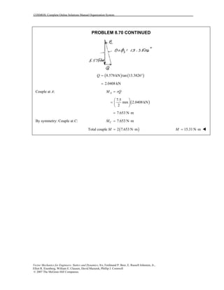
- 73. COSMOS: Complete Online Solutions Manual Organization System Vector Mechanics for Engineers: Statics and Dynamics, 8/e, Ferdinand P. Beer, E. Russell Johnston, Jr., Elliot R. Eisenberg, William E. Clausen, David Mazurek, Phillip J. Cornwell © 2007 The McGraw-Hill Companies. PROBLEM 8.70 CONTINUED ( ) ( )8.578 kN tan 13.3826Q = ° 2.0408 kN= Couple at A: AM rQ= ( ) 7.5 mm 2.0408 kN 2 = 7.653 N m= ⋅ By symmetry: Couple at C: 7.653 N mCM = ⋅ ( )Total couple 2 7.653 N mM = ⋅ 15.31 N mM = ⋅
- 74. COSMOS: Complete Online Solutions Manual Organization System Vector Mechanics for Engineers: Statics and Dynamics, 8/e, Ferdinand P. Beer, E. Russell Johnston, Jr., Elliot R. Eisenberg, William E. Clausen, David Mazurek, Phillip J. Cornwell © 2007 The McGraw-Hill Companies. Chapter 8, Solution 71. FBD joint D: By symmetry: AD CDF F= 0: 2 sin 25 4 kN 0y ADF FΣ = ° − = 4.7324 kNAD CDF F= = FBD joint A: By symmetry: AE ADF F= ( )0: 2 4.7324 kN cos25 0x ACF FΣ = − ° = 8.5780 kNACF = Block and incline at A:
- 75. COSMOS: Complete Online Solutions Manual Organization System Vector Mechanics for Engineers: Statics and Dynamics, 8/e, Ferdinand P. Beer, E. Russell Johnston, Jr., Elliot R. Eisenberg, William E. Clausen, David Mazurek, Phillip J. Cornwell © 2007 The McGraw-Hill Companies. PROBLEM 8.71 CONTINUED ( ) 1 2 mm tan 4.8518 7.5 mm θ π − = = ° 1 1 tan tan 0.15s sφ µ− − = = 8.5308sφ = ° 3.679sφ θ− = ° ( )8.5780 kN tan3.679Q = ° 0.55156 kNQ = Couple at : AA M Qr= ( ) 7.5 mm 0.55156 kN 2 = 2.0683 N m= ⋅ By symmetry: Couple at : 2.0683 N mCC M = ⋅ ( )Total couple 2 2.0683 N mM = ⋅ 4.14 N mM = ⋅
- 76. COSMOS: Complete Online Solutions Manual Organization System Vector Mechanics for Engineers: Statics and Dynamics, 8/e, Ferdinand P. Beer, E. Russell Johnston, Jr., Elliot R. Eisenberg, William E. Clausen, David Mazurek, Phillip J. Cornwell © 2007 The McGraw-Hill Companies. Chapter 8, Solution 72. FBD lower jaw: By symmetry 540 NB = 0: 540 N 540 N 0, 1080 NyF A AΣ = − + − = = (a) since A > B when finished, adjust A first when there will be no force Block/incline at B: (b) 1 4 mm tan 6.0566 12 mm θ π − = = ° ( )1 1 tan tan 0.35 19.2900s sφ µ− − = = = ° ( )540 N tan 25.3466 255.80 NQ = ° = ( )( )Couple 6 mm 255.80 N 1535 N mmrQ= = = ⋅ 1.535 N mM = ⋅
- 77. COSMOS: Complete Online Solutions Manual Organization System Vector Mechanics for Engineers: Statics and Dynamics, 8/e, Ferdinand P. Beer, E. Russell Johnston, Jr., Elliot R. Eisenberg, William E. Clausen, David Mazurek, Phillip J. Cornwell © 2007 The McGraw-Hill Companies. Chapter 8, Solution 73. FBD lower jaw: By symmetry 540 NB = 0: 540 N 540 N 0, 1080 NyF A AΣ = − + − = = since A > B, A should be adjusted first when no force is required. If instead, B is adjusted first, Block/incline at A: 1 4 mm tan 6.0566 12 mm θ π − = = ° ( )1 1 tan tan 0.35 19.2900s sφ µ− − = = = ° ( )1080 N tan 25.3466 511.59 NQ = ° = ( )( )Couple 6 mm 511.59 N 3069.5 N mmrQ= = = ⋅ 3.07 N mM = ⋅ Note that this is twice that required if A is adjusted first.
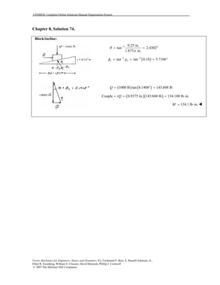
- 78. COSMOS: Complete Online Solutions Manual Organization System Vector Mechanics for Engineers: Statics and Dynamics, 8/e, Ferdinand P. Beer, E. Russell Johnston, Jr., Elliot R. Eisenberg, William E. Clausen, David Mazurek, Phillip J. Cornwell © 2007 The McGraw-Hill Companies. Chapter 8, Solution 74. Block/incline: 1 0.25 in. tan 2.4302 1.875 in. θ π − = = ° ( )1 1 tan tan 0.10 5.7106s sφ µ− − = = = ° ( ) ( )1000 lb tan 8.1408 143.048 lbQ = ° = ( )( )Couple 0.9375 in. 143.048 lb 134.108 lb in.rQ= = = ⋅ 134.1 lb in.M = ⋅
- 79. COSMOS: Complete Online Solutions Manual Organization System Vector Mechanics for Engineers: Statics and Dynamics, 8/e, Ferdinand P. Beer, E. Russell Johnston, Jr., Elliot R. Eisenberg, William E. Clausen, David Mazurek, Phillip J. Cornwell © 2007 The McGraw-Hill Companies. Chapter 8, Solution 75. FBD Bucket: ( )1 sin sin tanf s sr r rφ µ− = = ( ) ( )1 0.18 m sin tan 0.30 0.05172 m− = = ( ) ( )0: 1.6 m + 0.05172 m 0.05172 m 0AM T WΣ = − = 0.031314T W= ( ) kN 0.031314 50 Mg 9.81 Mg = 15.360 kN= 15.36 kNT = ! NOTE FOR PROBLEMS 8.75–8.89 Note to instructors: In this manual, the simplification sin ( )1 tan µ µ− ≈ is NOT used in the solution of journal bearing and axle friction problems. While this approximation may be valid for very small values of ,µ there is little if any reason to use it, and the error may be significant. For example, in Problems 8.76–8.79, 0.50,sµ = and the error made by using the approximation is about 11.8%.
- 80. COSMOS: Complete Online Solutions Manual Organization System Vector Mechanics for Engineers: Statics and Dynamics, 8/e, Ferdinand P. Beer, E. Russell Johnston, Jr., Elliot R. Eisenberg, William E. Clausen, David Mazurek, Phillip J. Cornwell © 2007 The McGraw-Hill Companies. Chapter 8, Solution 76. FBD Windlass: ( )1 sin sin tanf b s b sr r rφ µ− = = ( ) ( )1 1.5 in. sin tan 0.5 0.67082 in.− = = ( ) ( )0: 8 0.67082 in. 5 0.67082 in. 160 lb 0AM P Σ = − − + = 123.797 lbP = 123.8 lbP = NOTE FOR PROBLEMS 8.75–8.89 Note to instructors: In this manual, the simplification sin ( )1 tan µ µ− ≈ is NOT used in the solution of journal bearing and axle friction problems. While this approximation may be valid for very small values of ,µ there is little if any reason to use it, and the error may be significant. For example, in Problems 8.76–8.79, 0.50,sµ = and the error made by using the approximation is about 11.8%.
- 81. COSMOS: Complete Online Solutions Manual Organization System Vector Mechanics for Engineers: Statics and Dynamics, 8/e, Ferdinand P. Beer, E. Russell Johnston, Jr., Elliot R. Eisenberg, William E. Clausen, David Mazurek, Phillip J. Cornwell © 2007 The McGraw-Hill Companies. Chapter 8, Solution 77. FBD Windlass: ( )1 sin sin tanf s sr r rφ µ− = = ( ) ( )1 1.5 in. sin tan 0.5 0.67082 in.− = = ( ) ( ) ( )0: 8 0.67082 in. 5 0.67082 in. 160 lb 0AM P Σ = + − + = 104.6 lbP = NOTE FOR PROBLEMS 8.75–8.89 Note to instructors: In this manual, the simplification sin ( )1 tan µ µ− ≈ is NOT used in the solution of journal bearing and axle friction problems. While this approximation may be valid for very small values of ,µ there is little if any reason to use it, and the error may be significant. For example, in Problems 8.76–8.79, 0.50,sµ = and the error made by using the approximation is about 11.8%.
- 82. COSMOS: Complete Online Solutions Manual Organization System Vector Mechanics for Engineers: Statics and Dynamics, 8/e, Ferdinand P. Beer, E. Russell Johnston, Jr., Elliot R. Eisenberg, William E. Clausen, David Mazurek, Phillip J. Cornwell © 2007 The McGraw-Hill Companies. Chapter 8, Solution 78. FBD Windlass: ( )1 sin sin tanf s sr r rφ µ− = = ( ) ( )1 1.5 in. sin tan 0.50 0.67082 in.− = = ( ) ( ) ( )0: 8 0.67082 in. 5 0.67082 in. 160 lb 0AM P Σ = + − − = 79.9 lbP = NOTE FOR PROBLEMS 8.75–8.89 Note to instructors: In this manual, the simplification sin ( )1 tan µ µ− ≈ is NOT used in the solution of journal bearing and axle friction problems. While this approximation may be valid for very small values of ,µ there is little if any reason to use it, and the error may be significant. For example, in Problems 8.76–8.79, 0.50,sµ = and the error made by using the approximation is about 11.8%.
- 83. COSMOS: Complete Online Solutions Manual Organization System Vector Mechanics for Engineers: Statics and Dynamics, 8/e, Ferdinand P. Beer, E. Russell Johnston, Jr., Elliot R. Eisenberg, William E. Clausen, David Mazurek, Phillip J. Cornwell © 2007 The McGraw-Hill Companies. Chapter 8, Solution 79. FBD Windlass: ( )1 sin sin tanf s sr r rφ µ− = = ( ) ( )1 1.5 in. sin tan 0.50 0.67082 in.− = = ( ) ( ) ( )0: 8 0.67082 in. 5 0.67082 in. 160 lb 0AM P Σ = − − − = 94.5 lbP = NOTE FOR PROBLEMS 8.75–8.89 Note to instructors: In this manual, the simplification sin ( )1 tan µ µ− ≈ is NOT used in the solution of journal bearing and axle friction problems. While this approximation may be valid for very small values of ,µ there is little if any reason to use it, and the error may be significant. For example, in Problems 8.76–8.79, 0.50,sµ = and the error made by using the approximation is about 11.8%.
- 84. COSMOS: Complete Online Solutions Manual Organization System Vector Mechanics for Engineers: Statics and Dynamics, 8/e, Ferdinand P. Beer, E. Russell Johnston, Jr., Elliot R. Eisenberg, William E. Clausen, David Mazurek, Phillip J. Cornwell © 2007 The McGraw-Hill Companies. Chapter 8, Solution 80. (a) FBD lever (Impending CW rotation): (b) FBD lever (Impending CCW rotation): ( )( ) ( )( )0: 0.2 m 75 N 0.12 m 130 N 0C f fM r rΣ = + − − = 0.0029268 m 2.9268 mmfr = = sin f s s r r φ = * 1 1 2.9268 mm tan tan sin tan sin 18 mm f s s s r r µ φ − − = = = 0.34389= 0.344sµ = ( )( )0: 0.20 m 0.0029268 m 75 NDMΣ = − ( )0.12 m 0.0029268 m 0P− + = 120.2 NP = NOTE FOR PROBLEMS 8.75–8.89 Note to instructors: In this manual, the simplification sin ( )1 tan µ µ− ≈ is NOT used in the solution of journal bearing and axle friction problems. While this approximation may be valid for very small values of ,µ there is little if any reason to use it, and the error may be significant. For example, in Problems 8.76–8.79, 0.50,sµ = and the error made by using the approximation is about 11.8%.
- 85. COSMOS: Complete Online Solutions Manual Organization System Vector Mechanics for Engineers: Statics and Dynamics, 8/e, Ferdinand P. Beer, E. Russell Johnston, Jr., Elliot R. Eisenberg, William E. Clausen, David Mazurek, Phillip J. Cornwell © 2007 The McGraw-Hill Companies. Chapter 8, Solution 81. Pulley FBD’s: Left: Right: 30 mmpr = ( ) * 1 axle axlesin sin tanf k kr r rφ µ− = = ( ) ( )1 5 mm sin tan 0.2− = 0.98058 mm= Left: ( )( )0: 600 lb 2 0C p f p ABM r r r TΣ = − − = or ( ) ( ) 30 mm 0.98058 mm 600 N 290.19 N 2 30 mm ABT − = = 290 NABT = 0: 290.19 N 600 N 0y CDF TΣ = − + = or 309.81 NCDT = 310 NCDT = Right: ( ) ( )0: 0G p f CD p f EFM r r T r r TΣ = + − − = or ( ) 30 mm 0.98058 mm 309.81 N 330.75 N 30 mm 0.98058 mm EFT + = = − 331 NEFT = NOTE FOR PROBLEMS 8.75–8.89 Note to instructors: In this manual, the simplification sin ( )1 tan µ µ− ≈ is NOT used in the solution of journal bearing and axle friction problems. While this approximation may be valid for very small values of ,µ there is little if any reason to use it, and the error may be significant. For example, in Problems 8.76–8.79, 0.50,sµ = and the error made by using the approximation is about 11.8%.
- 86. COSMOS: Complete Online Solutions Manual Organization System Vector Mechanics for Engineers: Statics and Dynamics, 8/e, Ferdinand P. Beer, E. Russell Johnston, Jr., Elliot R. Eisenberg, William E. Clausen, David Mazurek, Phillip J. Cornwell © 2007 The McGraw-Hill Companies. Chapter 8, Solution 82. Pulley FBDs: Left: Right: 30 mmpr = ( ) * 1 axle axlesin sin tanf k kr r rφ µ− = = ( ) ( )1 5 mm sin tan 0.2− = 0.98058 mm= ( )( )0: 600 N 2 0C p f p ABM r r r TΣ = + − = or ( ) ( ) 30 mm 0.98058 mm 600 N 309.81 N 2 30 mm ABT + = = 310 NABT = 0: 600 N 0y AB CDF T TΣ = − + = or 600 N 309.81 N 290.19 NCDT = − = 290 NCDT = ( ) ( )0: 0H p f CD p f EFM r r T r r TΣ = − − + = or ( ) 30 mm 0.98058 mm 290.19 N 30 mm 0.98058 mm EFT − = + 272 NEFT = NOTE FOR PROBLEMS 8.75–8.89 Note to instructors: In this manual, the simplification sin ( )1 tan µ µ− ≈ is NOT used in the solution of journal bearing and axle friction problems. While this approximation may be valid for very small values of ,µ there is little if any reason to use it, and the error may be significant. For example, in Problems 8.76–8.79, 0.50,sµ = and the error made by using the approximation is about 11.8%.
- 87. COSMOS: Complete Online Solutions Manual Organization System Vector Mechanics for Engineers: Statics and Dynamics, 8/e, Ferdinand P. Beer, E. Russell Johnston, Jr., Elliot R. Eisenberg, William E. Clausen, David Mazurek, Phillip J. Cornwell © 2007 The McGraw-Hill Companies. Chapter 8, Solution 83. FBD link AB: Note: That AB is a two-force member. For impending motion, the pin forces are tangent to the friction circles. 1 sin 25 in. fr θ − = where ( ) * 1 sin sin tanf p s p sr r rφ µ− = = ( ) ( )1 1.5 in. sin tan 0.2 0.29417 in.− = = Then 1 0.29417 in. sin 1.3485 12.5 in. θ − = = ° (b) 1.349θ = ° vert horizcos sinR R R Rθ θ= = ( )horiz vert tan 50 kips tan1.3485 1.177 kipsR R θ= = ° = (a) horiz 1.177 kipsR = NOTE FOR PROBLEMS 8.75–8.89 Note to instructors: In this manual, the simplification sin ( )1 tan µ µ− ≈ is NOT used in the solution of journal bearing and axle friction problems. While this approximation may be valid for very small values of ,µ there is little if any reason to use it, and the error may be significant. For example, in Problems 8.76–8.79, 0.50,sµ = and the error made by using the approximation is about 11.8%.
- 88. COSMOS: Complete Online Solutions Manual Organization System Vector Mechanics for Engineers: Statics and Dynamics, 8/e, Ferdinand P. Beer, E. Russell Johnston, Jr., Elliot R. Eisenberg, William E. Clausen, David Mazurek, Phillip J. Cornwell © 2007 The McGraw-Hill Companies. Chapter 8, Solution 84. FBD gate: ( )2 1 66 kg 9.81m/s 647.46 NW = = ( )2 2 24 kg 9.81m/s 235.44 NW = = ( )1 sin sin tanf s s s sr r rφ µ− = = ( ) ( )1 0.012 m sin tan 0.2 0.0023534 m− = = ( ) ( ) ( )1 20: 0.6 m 0.15 m 1.8 m 0C f f fM r W r P r WΣ = − + − − + = ( )( ) ( )( ) ( ) 1.80235 m 235.44 N 0.59765 m 647.46 N 0.14765 m P − = 253.2 N= 253 NP = ! NOTE FOR PROBLEMS 8.75–8.89 Note to instructors: In this manual, the simplification sin ( )1 tan µ µ− ≈ is NOT used in the solution of journal bearing and axle friction problems. While this approximation may be valid for very small values of ,µ there is little if any reason to use it, and the error may be significant. For example, in Problems 8.76–8.79, 0.50,sµ = and the error made by using the approximation is about 11.8%.
- 89. COSMOS: Complete Online Solutions Manual Organization System Vector Mechanics for Engineers: Statics and Dynamics, 8/e, Ferdinand P. Beer, E. Russell Johnston, Jr., Elliot R. Eisenberg, William E. Clausen, David Mazurek, Phillip J. Cornwell © 2007 The McGraw-Hill Companies. Chapter 8, Solution 85. It is convenient to replace the ( )66 kg g and( )24 kg g weights with a single combined weight of ( )( )2 90 kg 9.81m/s 882.9 N,= located at a distance ( )( ) ( )( )1.8 m 24 kg 0.6 m 66 kg 0.04 m 90 kg x − = = to the right of B. ( ) ( ) ( ) * 1 1 sin sin tan 0.012 m sin tan 0.2f s s s sr r rφ µ− − = = = 0.0023534 m= FBD pulley + gate: 1 0.04 m 0.15 tan 14.931 0.15524 m 0.15 m cos OBα α − = = ° = = 1 1 0.0023534 m sin sin 0.8686 then 15.800 0.15524 m fr OB β θ α β− − = = = ° = + = ° tan 249.8 NP W θ= = 250 NP = ! NOTE FOR PROBLEMS 8.75–8.89 Note to instructors: In this manual, the simplification sin ( )1 tan µ µ− ≈ is NOT used in the solution of journal bearing and axle friction problems. While this approximation may be valid for very small values of ,µ there is little if any reason to use it, and the error may be significant. For example, in Problems 8.76–8.79, 0.50,sµ = and the error made by using the approximation is about 11.8%.
- 90. COSMOS: Complete Online Solutions Manual Organization System Vector Mechanics for Engineers: Statics and Dynamics, 8/e, Ferdinand P. Beer, E. Russell Johnston, Jr., Elliot R. Eisenberg, William E. Clausen, David Mazurek, Phillip J. Cornwell © 2007 The McGraw-Hill Companies. Chapter 8, Solution 86. FBD gate: ( )2 1 66 kg 9.81m/s 647.46 NW = = ( )2 2 24 kg 9.81m/s 235.44 NW = = ( ) * 1 sin sin tanf s s s sr r rφ µ− = = ( ) ( )1 0.012 m sin tan 0.2 0.0023534 m− = = ( ) ( ) ( )1 20: 0.6 m 0.15 m 1.8 m 0C f f fM r W r P r WΣ = + + + − − = ( )( ) ( )( )1.79765 m 235.44 N 0.60235 m 647.46 N 0.15235 m P − = 218.19 N= 218 NP = ! NOTE FOR PROBLEMS 8.75–8.89 Note to instructors: In this manual, the simplification sin ( )1 tan µ µ− ≈ is NOT used in the solution of journal bearing and axle friction problems. While this approximation may be valid for very small values of ,µ there is little if any reason to use it, and the error may be significant. For example, in Problems 8.76–8.79, 0.50,sµ = and the error made by using the approximation is about 11.8%.
- 91. COSMOS: Complete Online Solutions Manual Organization System Vector Mechanics for Engineers: Statics and Dynamics, 8/e, Ferdinand P. Beer, E. Russell Johnston, Jr., Elliot R. Eisenberg, William E. Clausen, David Mazurek, Phillip J. Cornwell © 2007 The McGraw-Hill Companies. Chapter 8, Solution 87. It is convenient to replace the ( )66 kg g and( )24 kg g weights with a single weight of ( )( )90 kg 9.81 N/kg 882.9 N,= located at a distance ( )( ) ( )( )1.8 m 24 kg 0.15 m 66 kg 0.04 m 90 kg x − = = to the right of B. FBD pulley + gate: ( ) ( ) ( ) * 1 1 sin sin tan 0.012 m sin tan 0.2f s s s sr r rφ µ− − = = = 0.0023534 mfr = 1 0.04 m 0.15 m tan 14.931 0.15524 m 0.15 m cos OBα α − = = ° = = 1 1 0.0023534 m sin sin 0.8686 then 14.062 0.15524 m fr OB β θ α β− − = = = ° = − = ° tan 221.1 NP W θ= = 221 NP = ! NOTE FOR PROBLEMS 8.75–8.89 Note to instructors: In this manual, the simplification sin ( )1 tan µ µ− ≈ is NOT used in the solution of journal bearing and axle friction problems. While this approximation may be valid for very small values of ,µ there is little if any reason to use it, and the error may be significant. For example, in Problems 8.76–8.79, 0.50,sµ = and the error made by using the approximation is about 11.8%.
- 92. COSMOS: Complete Online Solutions Manual Organization System Vector Mechanics for Engineers: Statics and Dynamics, 8/e, Ferdinand P. Beer, E. Russell Johnston, Jr., Elliot R. Eisenberg, William E. Clausen, David Mazurek, Phillip J. Cornwell © 2007 The McGraw-Hill Companies. Chapter 8, Solution 88. FBD Each wheel: ( )1 f axle axler r sin r sin tanφ µ− = = 0: sin 0 4 x P F R θΣ = − = 0: cos 0 4 y W F R θΣ = − = tan or tan P P W W θ θ∴ = = but ( )1axle sin sin tan f w w r r r r θ µ− = = (a) For impending motion, use 0.12sµ = ( )10.5 in. sin sin tan 0.12 5 in. θ − = 0.68267θ = ° ( ) ( )tan 500 lb tan 0.68267P W θ= = ° 5.96 lbP = (b) For constant speed, use 0.08kµ = ( )11 sin sin tan 0.08 10 θ − = 0.45691θ = ° ( ) ( )500 lb tan 0.45691P = ° 3.99 lbP = NOTE FOR PROBLEMS 8.75–8.89 Note to instructors: In this manual, the simplification sin ( )1 tan µ µ− ≈ is NOT used in the solution of journal bearing and axle friction problems. While this approximation may be valid for very small values of ,µ there is little if any reason to use it, and the error may be significant. For example, in Problems 8.76–8.79, 0.50,sµ = and the error made by using the approximation is about 11.8%.
- 93. COSMOS: Complete Online Solutions Manual Organization System Vector Mechanics for Engineers: Statics and Dynamics, 8/e, Ferdinand P. Beer, E. Russell Johnston, Jr., Elliot R. Eisenberg, William E. Clausen, David Mazurek, Phillip J. Cornwell © 2007 The McGraw-Hill Companies. Chapter 8, Solution 89. FBD Each wheel: For equilibrium (constant speed) the two forces R and 2 W must be equal and opposite, tangent to the friction circle, so ( )1 sin where tan slope f w r r θ θ − = = ( ) ( )1 1 sin tan sin tan 0.03 B k w r r µ− − = ( ) ( ) ( ) 1 1 sin tan 0.12 12.5 mm 49.666 mm sin tan 0.03 wr − − = = 99.3 mmwd = NOTE FOR PROBLEMS 8.75–8.89 Note to instructors: In this manual, the simplification sin ( )1 tan µ µ− ≈ is NOT used in the solution of journal bearing and axle friction problems. While this approximation may be valid for very small values of ,µ there is little if any reason to use it, and the error may be significant. For example, in Problems 8.76–8.79, 0.50,sµ = and the error made by using the approximation is about 11.8%.
- 94. COSMOS: Complete Online Solutions Manual Organization System Vector Mechanics for Engineers: Statics and Dynamics, 8/e, Ferdinand P. Beer, E. Russell Johnston, Jr., Elliot R. Eisenberg, William E. Clausen, David Mazurek, Phillip J. Cornwell © 2007 The McGraw-Hill Companies. Chapter 8, Solution 90. FBD ( )0: 8 in. 0,OM Q MΣ = − = 8 in. M Q = but, from equ. 8.9, ( )( ) 2 2 7 in. 0.60 10.1 lb 3 3 2 kM WRµ = = 14.14 lb= so, 14.14 , 8 Q = 1.768 lbQ =
- 95. COSMOS: Complete Online Solutions Manual Organization System Vector Mechanics for Engineers: Statics and Dynamics, 8/e, Ferdinand P. Beer, E. Russell Johnston, Jr., Elliot R. Eisenberg, William E. Clausen, David Mazurek, Phillip J. Cornwell © 2007 The McGraw-Hill Companies. Chapter 8, Solution 91. Eqn. 8.8 gives 3 3 3 3 2 1 2 1 2 2 2 2 2 1 2 1 2 1 3 3 s s R R D D M P P R R D D µ µ − − = = − − so ( )( )( )( ) ( ) ( ) ( ) 3 3 2 2 2 0.030 m 0.024 m1 0.15 80 kg 9.81 m/s 3 0.030 m 0.024 m M − = − 1.596 N mM = ⋅
- 96. COSMOS: Complete Online Solutions Manual Organization System Vector Mechanics for Engineers: Statics and Dynamics, 8/e, Ferdinand P. Beer, E. Russell Johnston, Jr., Elliot R. Eisenberg, William E. Clausen, David Mazurek, Phillip J. Cornwell © 2007 The McGraw-Hill Companies. Chapter 8, Solution 92. Let the normal force on A∆ be ,N∆ and N k A r ∆ = ∆ As in the text ,F N M r Fµ∆ = ∆ ∆ = ∆ The total normal force 2 0 00 lim R A k P N rdr d r π θ ∆ → = Σ∆ = ∫ ∫ ( )0 2 2 or 2 R P P kdr kR k R π π π = = =∫ The total couple 2 worn 0 00 lim R A k M M r rdr d r π µ θ ∆ → = Σ∆ = ∫ ∫ 2 2 worn 0 2 2 2 2 2 2 R R P R M k rdr k R πµ πµ πµ π = = =∫ or worn 1 2 M PRµ= Now new 2 3 M PRµ= [Eq. (8.9)] Thus 1 worn 2 2 new 3 3 75% 4 PRM M PR µ µ = = =
- 97. COSMOS: Complete Online Solutions Manual Organization System Vector Mechanics for Engineers: Statics and Dynamics, 8/e, Ferdinand P. Beer, E. Russell Johnston, Jr., Elliot R. Eisenberg, William E. Clausen, David Mazurek, Phillip J. Cornwell © 2007 The McGraw-Hill Companies. Chapter 8, Solution 93. Let normal force on A∆ be ,N∆ and N k A r ∆ = ∆ As in the text ,F N M r Fµ∆ = ∆ ∆ = ∆ The total normal force P is 2 1 2 00 lim R RA k P N rdr d r π θ ∆ → = Σ∆ = ∫ ∫ ( ) ( ) 2 1 2 1 2 1 2 2 or 2 R R P P kdr k R R k R R π π π = = − = − ∫ The total couple is 2 1 2 worn 00 lim R RA k M M r rdr d r π µ θ ∆ → = Σ∆ = ∫ ∫ ( ) ( ) ( ) ( ) 2 1 2 2 2 12 2 worn 2 1 2 1 2 2 R R P R R M k rdr k R R R R πµ πµ πµ π − = = − = − ∫ ( )worn 2 1 1 2 M P R Rµ= +
- 98. COSMOS: Complete Online Solutions Manual Organization System Vector Mechanics for Engineers: Statics and Dynamics, 8/e, Ferdinand P. Beer, E. Russell Johnston, Jr., Elliot R. Eisenberg, William E. Clausen, David Mazurek, Phillip J. Cornwell © 2007 The McGraw-Hill Companies. Chapter 8, Solution 94. Let normal force on A∆ be ,N∆ and , N k A ∆ = ∆ so sin r N k A A r s sφ θ ∆ ∆ = ∆ ∆ = ∆ ∆ ∆ = where φ is the azimuthal angle around the symmetry axis of rotation sinyF N kr rθ φ∆ = ∆ = ∆ ∆ Total vertical force 0 lim y A P F ∆ → = Σ∆ ( )2 2 1 1 2 0 2 R R R R P krdr d k rdr π φ π= =∫ ∫ ∫ ( ) ( ) 2 2 2 1 2 2 2 1 or P P k R R k R R π π = − = − Friction force F N k Aµ µ∆ = ∆ = ∆ Moment sin r M r F r krµ φ θ ∆ ∆ = ∆ = ∆ Total couple 2 1 2 2 00 lim sin R RA k M M r dr d π µ φ θ∆ → = Σ∆ = ∫ ∫ ( ) ( )2 1 2 3 3 2 32 2 2 3 2 2 sin 3 sin R R k P M r dr R R R R µ πµ π θ θ π = = − − ∫ 3 3 2 1 2 2 2 1 2 3 sin P R R M R R µ θ − = −
- 99. COSMOS: Complete Online Solutions Manual Organization System Vector Mechanics for Engineers: Statics and Dynamics, 8/e, Ferdinand P. Beer, E. Russell Johnston, Jr., Elliot R. Eisenberg, William E. Clausen, David Mazurek, Phillip J. Cornwell © 2007 The McGraw-Hill Companies. Chapter 8, Solution 95. If normal force per unit area (pressure) of the center is OP , then as a function of r, 1O r P P R = − 2 0 0 1 R N O r F W PdA P rdrd R π θ Σ = = = − ∫ ∫ ∫ 2 3 2 2 0 2 2 3 6 O O R R R W P d P R π θ π = − = ∫ so 2 3 O W P Rπ = For slipping, ( )kdF PdAµ= 2 0 0 Moment 1 R k O r rdF P r rdrd R π µ θ = = − ∫ ∫ ∫ 3 4 3 2 0 2 3 4 12 k O k O R R R P d P R π µ θ πµ = − = ∫ so 3 2 3 1 2 12 2 k k W R M WR R πµ µ π = = ( )0: 8 in. 0OM Q MΣ = − = ( ) ( )( ) 1 7 in. 0.6 10.1 lb 2 2 8 in. 8 in. M Q = = 1.326 lbQ =
- 100. COSMOS: Complete Online Solutions Manual Organization System Vector Mechanics for Engineers: Statics and Dynamics, 8/e, Ferdinand P. Beer, E. Russell Johnston, Jr., Elliot R. Eisenberg, William E. Clausen, David Mazurek, Phillip J. Cornwell © 2007 The McGraw-Hill Companies. Chapter 8, Solution 96. FBD pipe: 1 0.025 in. 0.0625 in. sin 1.00257 5 in. θ − + = = ° tanP W θ= for each pipe, so also for total ( ) ( )2000 lb tan 1.00257P = ° 35.0 lbP =
- 101. COSMOS: Complete Online Solutions Manual Organization System Vector Mechanics for Engineers: Statics and Dynamics, 8/e, Ferdinand P. Beer, E. Russell Johnston, Jr., Elliot R. Eisenberg, William E. Clausen, David Mazurek, Phillip J. Cornwell © 2007 The McGraw-Hill Companies. Chapter 8, Solution 97. FBD disk: tan slope 0.02θ = = ( )( )tan 60 mm 0.02b r θ= = 1.200 mmb =
- 102. COSMOS: Complete Online Solutions Manual Organization System Vector Mechanics for Engineers: Statics and Dynamics, 8/e, Ferdinand P. Beer, E. Russell Johnston, Jr., Elliot R. Eisenberg, William E. Clausen, David Mazurek, Phillip J. Cornwell © 2007 The McGraw-Hill Companies. Chapter 8, Solution 98. FBD wheel: 230 mmr = 1mmb = 1 sin b r θ − = 1 tan tan sin b P W W r θ − = = for each wheel, so for total ( )( )2 1 1 1000 kg 9.81m/s tan sin 230 P − = 42.7 NP =
- 103. COSMOS: Complete Online Solutions Manual Organization System Vector Mechanics for Engineers: Statics and Dynamics, 8/e, Ferdinand P. Beer, E. Russell Johnston, Jr., Elliot R. Eisenberg, William E. Clausen, David Mazurek, Phillip J. Cornwell © 2007 The McGraw-Hill Companies. Chapter 8, Solution 99. FBD wheel: ( )1 axle axlesin sin tan , orφ µ µ µ− = =f s kr r r sin tan f w r b r θ θ = + For small , sin tan , so tan f w r b r θ θ θ θ + 0: cos 0 4 y W F R θΣ = − = 0: sin 0 4 x P F R θΣ = − + = Solving: tan P W θ = so tan f w r b P W W r θ + = = (a) For impending slip, use ( )10.5 in. , sin tan 0.12 0.029786 in. 2 s frµ − = = so ( ) 0.02986 in. + 0.25 in. 500 lb 55.96 lb 2.5 in. P = = 56.0 lbP = (b) For constant speed, use ( )10.5 in. , sin tan 0.08 0.019936 in. 2 k frµ − = = so ( ) ( )0.019936 0.25 in. 500 lb 53.99 lb 2.5 in. P + = = 54.0 lbP =
- 104. COSMOS: Complete Online Solutions Manual Organization System Vector Mechanics for Engineers: Statics and Dynamics, 8/e, Ferdinand P. Beer, E. Russell Johnston, Jr., Elliot R. Eisenberg, William E. Clausen, David Mazurek, Phillip J. Cornwell © 2007 The McGraw-Hill Companies. Chapter 8, Solution 100. FBD wheel: For equilibrium (constant speed), R and 2 W are equal and opposite and tangent to the friction circle as shown ( ) ( ) ( )1 1 axle sin tan 12.5 mm sin tan 0.12f kr r µ− − = = 1.48932 mmfr = From diagram, sin tan f w r b r θ θ = + For small ,θ sin tan ,θ θ so tan f w r b r θ + tan slopeθ = 1.48932 mm 1.75 mm 107.977 mm 0.03 wr + = = 216 mmwd =
- 105. COSMOS: Complete Online Solutions Manual Organization System Vector Mechanics for Engineers: Statics and Dynamics, 8/e, Ferdinand P. Beer, E. Russell Johnston, Jr., Elliot R. Eisenberg, William E. Clausen, David Mazurek, Phillip J. Cornwell © 2007 The McGraw-Hill Companies. Chapter 8, Solution 101. Two full turns of rope → 4 radβ π= (a) 2 2 1 1 1 ln or lns s T T T T µ β µ β = = 1 20 000 N ln 0.329066 4 320 N sµ π = = 0.329sµ = (b) 2 1 1 ln s T T β µ = 1 80 000 N ln 0.329066 320 N = 16.799 rad= 2.67β = turns
- 106. COSMOS: Complete Online Solutions Manual Organization System Vector Mechanics for Engineers: Statics and Dynamics, 8/e, Ferdinand P. Beer, E. Russell Johnston, Jr., Elliot R. Eisenberg, William E. Clausen, David Mazurek, Phillip J. Cornwell © 2007 The McGraw-Hill Companies. Chapter 8, Solution 102. FBD A: ( )( )2 10 kg 9.81 m/s 98.1 NAW = = 0: sin30 0, 2 A x A A A W F T W TΣ = − ° = = FBD B: 0: sin30 0, 2 B x B B B W F W T T′Σ = ° − = = (a) Motion of B impends up incline and 8 kgBm = 1 1 , ln lnsA A A s B B B T T W e T T W µ β µ β β = = = 1 3 10 kg ln ln 8 kgB Am mβ π = = From hint, β is not dependent on shape of support 0.21309sµ = 0.213sµ = (b) For maximum ,Bm motion of B impend down incline 0.21309 3, 1.250sB B A A A T e T T e T T π µ β = = = 1.25B AW W∴ = and ( )1.25 1.25 10 kgB Am m= = max 12.50 kgBm =
- 107. COSMOS: Complete Online Solutions Manual Organization System Vector Mechanics for Engineers: Statics and Dynamics, 8/e, Ferdinand P. Beer, E. Russell Johnston, Jr., Elliot R. Eisenberg, William E. Clausen, David Mazurek, Phillip J. Cornwell © 2007 The McGraw-Hill Companies. Chapter 8, Solution 103. FBD A: 0: sin30 0, 2 A x A A A W F T W TΣ = − ° = = FBD B: 0: sin30 0, 2 B x B B B W F W T T′Σ = ° − = = For min,Bm motion of B impends up incline And 0.50 3 1.68809A B T e T π = = But 1.68809A A A B B B m W T m W T = = = so min 5.9238 kgBm = From hint, β is not dependent on shape of C For max,Bm motion of B impends down incline so 0.50 3 1.68809sB B B A A A m W T e e m W T β π µ = = = = = so max 16.881 kgBm = For equilibrium 5.92 kg 16.88 kgBm≤ ≤
- 108. COSMOS: Complete Online Solutions Manual Organization System Vector Mechanics for Engineers: Statics and Dynamics, 8/e, Ferdinand P. Beer, E. Russell Johnston, Jr., Elliot R. Eisenberg, William E. Clausen, David Mazurek, Phillip J. Cornwell © 2007 The McGraw-Hill Companies. Chapter 8, Solution 104. 1.5 turns 3 radβ π= = For impending motion of W up ( ) ( )s 0.15 3 1177.2 NP We e πµ β = = 4839.7 N= For impending motion of W down ( ) ( )0.15 3 1177.2 NsP We e πµ β −− = = 286.3 N= For equilibrium 286 N 4.84 kNP≤ ≤
- 109. COSMOS: Complete Online Solutions Manual Organization System Vector Mechanics for Engineers: Statics and Dynamics, 8/e, Ferdinand P. Beer, E. Russell Johnston, Jr., Elliot R. Eisenberg, William E. Clausen, David Mazurek, Phillip J. Cornwell © 2007 The McGraw-Hill Companies. Chapter 8, Solution 105. Horizontal pipe: Vertical pipe Contact angles 2 H π β = Contact angle Vβ π= 0.25sHµ = 0.2sVµ = For P to impend downward, ( ) ( ) ( )2 2 2 2 100 lbsH sH sH sHsV sVP e Q e e R e e e π π π πµ µ µ µµ π µ π = = = ( ) ( ) ( ) 0.45 max 100 lb 100 lb 411.12 lbsH sV P e e π µ µ π+ = = = For 100 lb to impend downward, the ratios are reversed, so 0.45 min100 lb , 24.324 lbPe Pπ = = So, for equilibrium, 24.3 lb 411 lbP≤ ≤
- 110. COSMOS: Complete Online Solutions Manual Organization System Vector Mechanics for Engineers: Statics and Dynamics, 8/e, Ferdinand P. Beer, E. Russell Johnston, Jr., Elliot R. Eisenberg, William E. Clausen, David Mazurek, Phillip J. Cornwell © 2007 The McGraw-Hill Companies. Chapter 8, Solution 106. Horizontal pipe Vertical pipe Contact angles 2 H π β = Contact angle Vβ π= 0.30sHµ = ?sVµ = For min,P the 100 lb force impends downward, and ( ) ( ) PeeeQeeRe sHsVssVsHsH = = = 2222 lb100 ππ π ππ µπµµπµµµ ( ) ( ) ( )0.30 0.30 100 lb 20 lb , so 5sV sV e e π µ π µ+ + = = (a) For maxP the force P impends downward, and the ratios are reversed, so ( )max 5 100 lb 500 lbP = = (b) ( )0.30 ln5sVπ µ+ = 1 ln5 0.30 0.21230sVµ π = − = 0.212sVµ =
- 111. COSMOS: Complete Online Solutions Manual Organization System Vector Mechanics for Engineers: Statics and Dynamics, 8/e, Ferdinand P. Beer, E. Russell Johnston, Jr., Elliot R. Eisenberg, William E. Clausen, David Mazurek, Phillip J. Cornwell © 2007 The McGraw-Hill Companies. Chapter 8, Solution 107. FBD motor and mount: Impending belt slip: cw rotation 0.40 2 1 1 13.5136sT T e T e Tµ β π = = = ( )( ) ( ) ( )2 10: 12 in. 175 lb 7 in. 13 in. 0DM T TΣ = − − = ( )( ) 12100 lb 7 in. 3.5136 13 in. T = + 1 2 155.858 lb, 3.5136 196.263 lbT T T= = = FBD drum at B: ( )( )0: 3 in. 196.263 lb 55.858 lb 0B BM MΣ = − − = 421 lb in.BM = ⋅ 3 in.r = (Compare to 857 lb in.⋅ using V-belt, Problem 8.130)
- 112. COSMOS: Complete Online Solutions Manual Organization System Vector Mechanics for Engineers: Statics and Dynamics, 8/e, Ferdinand P. Beer, E. Russell Johnston, Jr., Elliot R. Eisenberg, William E. Clausen, David Mazurek, Phillip J. Cornwell © 2007 The McGraw-Hill Companies. Chapter 8, Solution 108. FBD motor and mount: Impending belt slip: ccw rotation 0.40 1 2 2 23.5136sT T e T e Tµ β π = = = ( )( ) ( ) ( )1 20: 12 in. 175 lb 13 in. 7 in. 0DM T TΣ = − − = ( )( ) 22100 lb 13 in. 3.5136 7 in. 0T = + = 2 1 239.866 lb, 3.5136 140.072 lbT T T= = = FBD drum at B: ( )( )0: 3 in. 140.072 lb 39.866 lb 0B BM MΣ = − − = 301 lb in.BM = ⋅
- 113. COSMOS: Complete Online Solutions Manual Organization System Vector Mechanics for Engineers: Statics and Dynamics, 8/e, Ferdinand P. Beer, E. Russell Johnston, Jr., Elliot R. Eisenberg, William E. Clausen, David Mazurek, Phillip J. Cornwell © 2007 The McGraw-Hill Companies. Chapter 8, Solution 109. FBD lower portion of belt: 0: 48 N 0, 48 Ny D DF N NΣ = − = = Slip on both platen and wood ( )0.10 48 N 4.8 ND kD DF Nµ= = = ( )48 NE kE E kEF Nµ µ= = FBD Drum A (assume free to rotate) ( )0: 4.8 N 48 N 0x A B kEF T T µΣ = − − − = ( )4.8 N + 48 NB A kET T µ= + (1) ( )0: 0,A A A T T AM r T T T TΣ = − = = (2) FBD Drive drum B ( )0: 0B B T BM M r T TΣ = + − = 2.4 N m 96 N 0.025 N B T TT T T ⋅ = + = + Impending slip on drum, 0.35s B T TT T e T eµ β π = = so 0.35 96 N , 47.932 NT T TT T e Tπ + = = 143.932 NBT = From (2) above, ,A TT T= so (a) min lower 47.9 NT = From (1) above, ( )143.932 N 47.932 N + 4.8 N + 48 NkEµ= So (b) 1.900kEµ =
- 114. COSMOS: Complete Online Solutions Manual Organization System Vector Mechanics for Engineers: Statics and Dynamics, 8/e, Ferdinand P. Beer, E. Russell Johnston, Jr., Elliot R. Eisenberg, William E. Clausen, David Mazurek, Phillip J. Cornwell © 2007 The McGraw-Hill Companies. Chapter 8, Solution 110. FBD Flywheel: ( )( )0: 0.225 m 12.60 N m 0C B AM T TΣ = − − ⋅ = 56 N, 56 NB A B AT T T T− = = + Also, since the belt doesn’t change length, the additional stretch in spring B equals the decrease in stretch of spring A. Thus the increase in BT equals the decrease in .AT Thus ( ) ( )70 N 70 N 140 NB AT T T T+ = + ∆ + − ∆ = ( )56 N 140 N, 42 NA A AT T T+ + = = 42 N 56 N 98 NBT = + = (a) 42.0 NAT = 98.0 NBT = For slip ,k B AT T eµ β = or 1 ln B k A T T µ β = 1 98 ln 0.2697 42 kµ π = = (b) 0.230kµ =
- 115. COSMOS: Complete Online Solutions Manual Organization System Vector Mechanics for Engineers: Statics and Dynamics, 8/e, Ferdinand P. Beer, E. Russell Johnston, Jr., Elliot R. Eisenberg, William E. Clausen, David Mazurek, Phillip J. Cornwell © 2007 The McGraw-Hill Companies. Chapter 8, Solution 111. FBD Flywheel: Slip of belt: 0.20k B A AT T e T eµ β π = = Also, since the belt doesn’t change length, the increase in stretch of spring B equals the decrease in stretch of spring A. Therefore the increase in BT equals the decrease in ,AT and the sum is unchanged, so 80 N 80 N 160 NA BT T+ = + = ( )0.20 1 160 N,AT e π ∴ + = so 55.663 NAT = 104.337 NBT = (a) 55.7 NAT = 104.3 NBT = ( )( )0: 0.225 m 0C B A CM T T MΣ = − − = ( )( )0.225 m 104.337 N 55.663 NCM = − (b) 10.95 N mCM = ⋅
- 116. COSMOS: Complete Online Solutions Manual Organization System Vector Mechanics for Engineers: Statics and Dynamics, 8/e, Ferdinand P. Beer, E. Russell Johnston, Jr., Elliot R. Eisenberg, William E. Clausen, David Mazurek, Phillip J. Cornwell © 2007 The McGraw-Hill Companies. Chapter 8, Solution 112. FBD Lever: ( )( ) ( )0: 60 mm 240 N 40 mm cos30 0E BDM FΣ = − ° = 415.69 NBDF = FBD Drum: Belt slip: 2 1 kT T eµ β = ( ) ( )0.25 5.5851 415.69 N e= 1679.44 N= ( )2 10: 0CM r T T MΣ = − − = ( )( )0.08 m 1679.44 N 415.69 N 0M− − = 101.1 N mM = ⋅
- 117. COSMOS: Complete Online Solutions Manual Organization System Vector Mechanics for Engineers: Statics and Dynamics, 8/e, Ferdinand P. Beer, E. Russell Johnston, Jr., Elliot R. Eisenberg, William E. Clausen, David Mazurek, Phillip J. Cornwell © 2007 The McGraw-Hill Companies. Chapter 8, Solution 113. FBD Drum: (a) With 125 lb ftEM = ⋅ ( )( ) ( )0: 7 in. 125 lb ft 0E A CM T TΣ = − − ⋅ = 214.29 lbA CT T− = Belt slip: ( )7 6 0.30 3.0028k A C C CT T e T e T π µ β = = = so 2.0028 214.9 lb,CT = 106.995 lbCT = 321.28 lbAT = FBD Lever: ( ) ( ) ( )0: 15 in. 2 in. 7.5 in. 0B C AM P T TΣ = + − = (1) ( )( ) ( )( )7.5 in. 321.28 lb 2 in. 106.995 lb 17 in. P − = 129.2 lbP = (b) With 125 lb ftEM = ⋅ , the drum analysis will be reversed, and will yield 106.995 lb,AT = 321.28 lbCT = Eqn. (1) will remain the same, so ( )( ) ( )( )7.5 in. 106.995 lb 2 in. 321.28 lb 17 in. P − = 9.41 lbP =
- 118. COSMOS: Complete Online Solutions Manual Organization System Vector Mechanics for Engineers: Statics and Dynamics, 8/e, Ferdinand P. Beer, E. Russell Johnston, Jr., Elliot R. Eisenberg, William E. Clausen, David Mazurek, Phillip J. Cornwell © 2007 The McGraw-Hill Companies. Chapter 8, Solution 114. FBD Lever: If brake is self-locking, no force P is required ( ) ( )0: 2 in. 7.5 in. 0B C AM T TΣ = − = 3.75C AT T= For impending slip on drum: s C AT T eµ β = 3.75,seµ β ∴ = or 1 ln3.75sµ β = With 7 , 6 π β = 0.361sµ =
- 119. COSMOS: Complete Online Solutions Manual Organization System Vector Mechanics for Engineers: Statics and Dynamics, 8/e, Ferdinand P. Beer, E. Russell Johnston, Jr., Elliot R. Eisenberg, William E. Clausen, David Mazurek, Phillip J. Cornwell © 2007 The McGraw-Hill Companies. Chapter 8, Solution 115. FBD Lever: ( ) ( )0: 40 mm 100 mm 0, 2.5B C A C AM T T T TΣ = − = = FBD Drum: (a) For impending slip ccw: max 4.5 kNCT T= = so 1.8 kN 2.5 C A T T = = ( )( )0: 0.16 m 1.8 kN 4.5 kN 0D DM MΣ = + − = 0.432 kN mDM = ⋅ 432 N mDM = ⋅ (b) For impending slip ccw, s C AT T eµ β = or 1 3 ln ln 2.5 0.21875 4 C s A T T µ β π = = = 0.219sµ =
- 120. COSMOS: Complete Online Solutions Manual Organization System Vector Mechanics for Engineers: Statics and Dynamics, 8/e, Ferdinand P. Beer, E. Russell Johnston, Jr., Elliot R. Eisenberg, William E. Clausen, David Mazurek, Phillip J. Cornwell © 2007 The McGraw-Hill Companies. Chapter 8, Solution 116. (a) For minimum Cm with blocks at rest, impending slip of A is down/left. Note: 1 1 tan tan 0.30 16.7 30 ,s sφ µ− − = = = ° < ° so min 0Cm > FBD A: ( )( )2 6 kg 9.81 m/s 58.86 NAW = = 0: cos30 0, cos30y A A A AF N W N WΣ = − ° = = ° Impending slip: 0.30 cos30A s A AF N Wµ= = ° ( )0: sin30 0, sin30 0.30cos30x A A A A AF T F W T WΣ = + − ° = = ° − ° 14.1377 N= FBD Drum: If blocks don’t move, belt slips on drum, so ( )0.2 0.87266 14.1377 N 1.19069k A C C CT T e T e Tµ β = = = = so 11.8735 NCT = FBD C: 0: cos20 0, cos20y C C C CF N W N W′Σ = − ° = = ° Impending slip: 0.30 cos20C s C CF N Wµ= = ° 0: 0.30 cos20 sin 20 11.8735 N 0x C CF W W′Σ = ° + ° − = 2 19.0302 N, 1.93988 kg 9.81 m/s C C C W W m= = = 1.940 kgCm = continued
- 121. COSMOS: Complete Online Solutions Manual Organization System Vector Mechanics for Engineers: Statics and Dynamics, 8/e, Ferdinand P. Beer, E. Russell Johnston, Jr., Elliot R. Eisenberg, William E. Clausen, David Mazurek, Phillip J. Cornwell © 2007 The McGraw-Hill Companies. (b) For motion of A to impend up/right FBD A: As in part (a) cos30 , 0.30 cos30A A A AN W F W= ° = ° ( )0: sin30 0.30cos30 0x A AF T WΣ = − ° + ° = 44.722 NAT = Also, as in part (a) 1.19069 ,k A C CT T e Tµ β = = so 44.722 N 1.19069 CT = 37.560 NCT = FBD C: As in part (a) 0.30 cos20C CF W= ° ( )0: sin 20 0.30cos20 37.560 N 0x CF W′Σ = ° − ° − = 2 624.83 N, 63.69 kg 9.81 m/s C C C W W m= = = 63.7 kgCm = (c) For uniform motion of A up and B down, and minimum ,Cm there will be impending slip of the rope on the drum. FBD A is same as in (b) but 0.20 cos30A k A AF N Wµ= = ° and ( )0: sin30 0.20cos30 0, 39.625 Nx A A AF T W TΣ = − ° + ° = = Drum analysis, with impending slip, s A CT T eµ β = ( )0.30 0.87266 39.625 N 1.29926C CT e T= = or 30.498 NCT = FBD C is same as in (b), but 0.20 cos20C k C CF N Wµ= = ° and ( )0: sin 20 0.20cos20 0x C CF W T′Σ = ° − ° − = 2 30.498 N 197.934 N 197.933 N, 0.154082 9.81 m/s C CW m= = = 20.2 kgCm =
- 122. COSMOS: Complete Online Solutions Manual Organization System Vector Mechanics for Engineers: Statics and Dynamics, 8/e, Ferdinand P. Beer, E. Russell Johnston, Jr., Elliot R. Eisenberg, William E. Clausen, David Mazurek, Phillip J. Cornwell © 2007 The McGraw-Hill Companies. Chapter 8, Solution 117. Geometry and force rotation: Let 1 50 mm cos 60 s , , 100 mm EBC DBE FAE GAEα − = = = ° = Then contact angles are 4 360 120 240 rad 3 B π β = ° − ° = ° = for cord on upper cylinder, and 30 rad 6 A π β = ° = for each cord contact on lower cylinder. Let the force in section FFC T= Let the force in section GDG T= With A fixed and the cord moving, ( )6 0.25 1.13985k A GT We We W π µ β = = = For maximum W, slip impends on drum B, so s B B FT T eµ β = or s B F GT T e µ β− = ( )4 3 0.30 1.13985 0.32441FT We W π− = = For slip at F ( )6 0.25 1 0.32441 0.36978k A FW T e We W π µ β = = = so 12.7043W W= and 2.7043 in.m = ( )2.7043 75 kg= 203 kgm =
- 123. COSMOS: Complete Online Solutions Manual Organization System Vector Mechanics for Engineers: Statics and Dynamics, 8/e, Ferdinand P. Beer, E. Russell Johnston, Jr., Elliot R. Eisenberg, William E. Clausen, David Mazurek, Phillip J. Cornwell © 2007 The McGraw-Hill Companies. Chapter 8, Solution 118. Geometry and force notation: Note: 1 sin 30 rad, 2 6 r r π θ − = = ° = so contact angles are: 2 , 2 6 3 C D E π π π β β β π= = + = = (a) For all pulleys locked, slip impends at all contacts If AW impends downward, ( )1 2 1 216 lb , ,s E s D s C AT e T T e W T eµ β µ β µ β = = = so ( ) ( ) ( ) ( )7 3 0.20 16 lb 16 lb 69.315 lbs C D E AW e e π µ β β β+ + = = = If AW impends upward all ratios are inverted, so ( ) ( )7 3 0.20 16 lbAW e π− = 3.6933 lb= For equilibrium, 3.69 lb 69.3 lbAW≤ ≤ (b) If pulley D is free to rotate, 1 2T T= while the other ratios remain as in (a) For AW impending down ( ) ( ) ( ) ( )5 3 0.20 16 lb 16 lbs C E AW e e π µ β β+ = = 45.594 lbAW = For AW impending upward, ( ) ( )3 0.2 16 lb 5.6147 lbAW e π5− = = For equilibrium 5.61 lb 45.6 lbAW≤ ≤
- 124. COSMOS: Complete Online Solutions Manual Organization System Vector Mechanics for Engineers: Statics and Dynamics, 8/e, Ferdinand P. Beer, E. Russell Johnston, Jr., Elliot R. Eisenberg, William E. Clausen, David Mazurek, Phillip J. Cornwell © 2007 The McGraw-Hill Companies. Chapter 8, Solution 119. Geometry and force notation: 1 sin 30 , 2 6 r r π θ − = = ° = so contact angles are: 2 , 2 6 3 C D E π π π β β β π= = + = = (a) D and E fixed, so slip on these surfaces. For maximum ,AN slip impends on pulley C 2 ,s C AW T eµ β = and ( )1 2 1, 16 lbk D k ET T e T eµ β µ β = = so ( ) ( ) ( ) ( ) ( )5 2 3 3 0.15 0.20 16 lb 16 lb 11.09 lbk E D s C AW e e e e π π µ β β µ β −− + = = = (b) C and D fixed, so slip there. For maximum ,AW slip impends on E so ( )1 1 2 216 lb , ,s E k D k C AT e T T e T W eµ β µ β µ β = = = so ( ) ( ) ( ) ( )4 3 0.150.20 16 lb 16 lb 16 lbk C Ds E AW e e e e π µ β βµ β π −− + = = = 16.00 lbAW =
- 125. COSMOS: Complete Online Solutions Manual Organization System Vector Mechanics for Engineers: Statics and Dynamics, 8/e, Ferdinand P. Beer, E. Russell Johnston, Jr., Elliot R. Eisenberg, William E. Clausen, David Mazurek, Phillip J. Cornwell © 2007 The McGraw-Hill Companies. Chapter 8, Solution 120. Geometry and force notation: 1 5 in. sin 30 rad, 10 in. 6 π θ − = = ° = so contact angles are: 5 2 , , 6 6 2 6 3 2 C D E π π π π π π β π β β= − = = + = = (a) All pulleys locked with impending slip at all. If AW impends upward, 1 ,s C AT W eµ β = ( )2 1 2, 16 lb ,s D s ET T e T eµ β µ β = = so ( ) ( ) ( ) ( )5 34 6 6 6 0.20 16 lb 16 lbs C D E AW e e πµ β β β − + +− + + = = 4.5538 lbAW = If AW impends downward all ratios are inverted so ( ) ( )0.20 2 16 lb 56.217 lbAW e π+ = = For equilibrium, 4.55 lb 56.2 lbAW≤ ≤ (b) Pulley D is free to rotate so 1 2T T= , other ratios are the same If AW impends upward, ( ) ( ) ( ) ( )4 3 0.20 16 lb 16 lbs C E AW e e π µ β β −− + = = 6.9229 lbAW = If AW impends downward, ratios are inverted, ( ) ( )4 3 0.20 16 lbAW e π+ = 36.979 lbAW = For equilibrium 6.92 lb 37.0 lbAW≤ ≤
- 126. COSMOS: Complete Online Solutions Manual Organization System Vector Mechanics for Engineers: Statics and Dynamics, 8/e, Ferdinand P. Beer, E. Russell Johnston, Jr., Elliot R. Eisenberg, William E. Clausen, David Mazurek, Phillip J. Cornwell © 2007 The McGraw-Hill Companies. Chapter 8, Solution 121. Geometry and force notation: 1 5 in. sin 30 rad, 10 in. 6 π θ − = = ° = so contact angles are: 5 2 , , 6 6 2 6 3 2 C D E π π π π π π β π β β= − = = + = = (a) D and E fixed, so slip at these surfaces, For maximum ,AW slip impends on C. 1 2 1 2, , 16 lbs C k D k E AW T e T T e T eµ β µ β µ β = = = so ( ) ( )16 lb k D E s C AW e e µ β β µ β− + = ( ) ( ) ( )7 5 6 6 0.15 0.20 16 lb 15.5866 lbe e π π− = = max 15.59 lbAW = (b) C and D fixed, so slip at these surfaces—impending slip on E ( )1 2 1 2, , 16 lbk C k D s E AT W e T T e T eµ β µ β µ β = = = so ( ) ( ) ( ) ( ) ( )3 2 2 0.15 0.20 16 lb 16 lbk C D s E AW e e e e π π µ β β µ β −− + = = 10.8037 lb,AW = max 10.80 lbAW =
- 127. COSMOS: Complete Online Solutions Manual Organization System Vector Mechanics for Engineers: Statics and Dynamics, 8/e, Ferdinand P. Beer, E. Russell Johnston, Jr., Elliot R. Eisenberg, William E. Clausen, David Mazurek, Phillip J. Cornwell © 2007 The McGraw-Hill Companies. Chapter 8, Solution 122. FBD drum B: ( )( )0: 0.02 m 0.30 N m 0B AM T TΣ = − − ⋅ = 0.30 N m 15 N 0.02 m AT T ⋅ − = = Impending slip: 0.40s AT Te Teµ β π = = Solving; ( )0.40 1 15 NT e π − = 5.9676 NT = If C is free to rotate P T= min 5.97 NP =
- 128. COSMOS: Complete Online Solutions Manual Organization System Vector Mechanics for Engineers: Statics and Dynamics, 8/e, Ferdinand P. Beer, E. Russell Johnston, Jr., Elliot R. Eisenberg, William E. Clausen, David Mazurek, Phillip J. Cornwell © 2007 The McGraw-Hill Companies. Chapter 8, Solution 123. FBD drum B: ( )( )0: 0.02 m 0.3 N m 0B AM T TΣ = − − ⋅ = 15 NAT T− = Impending slip: 0.40s B AT Te Teµ β π = = Solving, ( )0.40 1 15 NT e π − = 5.9676 NT = If C is frozen, tape must slip there, so ( ) ( )2 0.30 5.9676 N 9.5599 Nk CP Te e π µ β = = = min 9.56 NP =
- 129. COSMOS: Complete Online Solutions Manual Organization System Vector Mechanics for Engineers: Statics and Dynamics, 8/e, Ferdinand P. Beer, E. Russell Johnston, Jr., Elliot R. Eisenberg, William E. Clausen, David Mazurek, Phillip J. Cornwell © 2007 The McGraw-Hill Companies. Chapter 8, Solution 124. FBD pin B: Drum: Lever: (a) By symmetry: 1 2T T= 1 1 2 2 0: 2 0 or 2 2 2 yF B T B T T Σ = − = = = (1) For impending rotation : 3 1 2 4 3 max, so 5.6 kNT T T T T T> = > = = Then ( ) ( )4 6 0.25 1 3 5.6 kNs LT T e e π π µ β − +− = = or 1 24.03706 kNT T= = and ( ) ( )3 4 0.25 4 2 4.03706 kNs RT T e e π µ β −− = = or 4 2.23998 kNT = ( )0 4 3 2 10: 0FM M r T T T TΣ = + − + − = or ( )( )0 0.16 m 5.6 kN 2.23998 kN 0.5376 kN mM = − = ⋅ 0 538 N m= ⋅M (b) Using Equation (1) ( )12 2 4.03706 kNB T= = 5.70927 kN= ( )( ) ( )0: 0.05 m 5.70927 kN 0.25 m 0DM PΣ = − = 1.142 kN=P
- 130. COSMOS: Complete Online Solutions Manual Organization System Vector Mechanics for Engineers: Statics and Dynamics, 8/e, Ferdinand P. Beer, E. Russell Johnston, Jr., Elliot R. Eisenberg, William E. Clausen, David Mazurek, Phillip J. Cornwell © 2007 The McGraw-Hill Companies. Chapter 8, Solution 125. FBD pin B: FBD Drum: FBD Lever: (a) By symmetry: 1 2T T= 1 1 2 0: 2 0 or 2 2 yF B T B T Σ = − = = (1) For impending rotation : 4 2 1 3 4 max, so 5.6 kNT T T T T T> = > = = Then ( ) ( )3 4 0.25 2 4 5.6 kNs RT T e e π µ β −− = = or 2 13.10719 kNT T= = and ( ) ( )4 6 0.25 3 1 3.10719 kNs LT T e e π π µ β − +− = = or 3 2.23999 kNT = ( )0 2 1 3 40: 0FM M r T T T TΣ = + − + − = ( )( )0 160 mm 5.6 kN 2.23999 kN 537.6 N mM = − = ⋅ 0 538 N m= ⋅M (b) Using Equation (1) ( )12 2 3.10719 kNB T= = 4.3942 kNB = ( )( ) ( )0: 0.05 m 4.3942 kN 0.25 m 0DM PΣ = − = 879 N=P
- 131. COSMOS: Complete Online Solutions Manual Organization System Vector Mechanics for Engineers: Statics and Dynamics, 8/e, Ferdinand P. Beer, E. Russell Johnston, Jr., Elliot R. Eisenberg, William E. Clausen, David Mazurek, Phillip J. Cornwell © 2007 The McGraw-Hill Companies. Chapter 8, Solution 126. FBD wrench: Note: ( )0.2 m , 0.03 m sin65 EC EA EC= = − ° 65θ = ° so 295 5.1487 radβ = ° = 0.20 m 0.20 m 0: 0.03 m cos65 0.03 m 0 sin65 sin65 EM F T Σ = − − ° − = ° ° 3.01408T F= 0: sin65 cos65 0xF N F TΣ = ° + ° − = Impending slip: , s F N µ = so sin65 cos65 s F T µ ° = + ° = or sin65 cos65 3.01408 sµ ° + ° = 0.3497sµ = Must still check slip of belt on pipe FBD small portion of belt at A: 1 20: 0nF N NΣ = − = Impending slip, both sides: 1 1 2 2,s sF N F Nµ µ= = so 1 2F F F= = 0: 2 0, 2t A AF F T T FΣ = − = = Impending slip of belt on pipe: s AT T eµ β = or 1 1 3.01408 ln ln 0.0797 2 5.1487 2 s T F µ β = = = Above controls, so for self-locking, need 0.350sµ =
- 132. COSMOS: Complete Online Solutions Manual Organization System Vector Mechanics for Engineers: Statics and Dynamics, 8/e, Ferdinand P. Beer, E. Russell Johnston, Jr., Elliot R. Eisenberg, William E. Clausen, David Mazurek, Phillip J. Cornwell © 2007 The McGraw-Hill Companies. Chapter 8, Solution 127. FBD wrench Note: ( )0.20 m , 0.03 m sin75 EC EA EC= = − ° 75θ = ° so 285 4.9742 radβ = ° = 0.20 m 0.20 m 0: 0.03 m cos75 0.03 m 0 sin75 sin 75 EM F T Σ = − − ° − = ° ° 7.5056T F= 0: sin75 cos75 0xF N F TΣ = ° + ° − = Impending slip: , s F N µ = so sin75 cos75 7.5056 s F T F µ ° = + ° = = sin 75 cos75 7.5056 sµ ° + ° = 0.1333sµ = Must still check impending slip of belt on pipe FBD small portion of belt at A 1 20: 0nF N NΣ = − = Impending slip 1 1 2 2,s sF N F Nµ µ= = so 1 2F F F= = 0: 2 0, 2t A AF F T T FΣ = − = = Impending slip of belt on pipe s AT T eµ β = or 1 1 7.5056 ln ln 0.2659 2 4.9742 2 s T F µ β = = = This controls, so for self locking, min 0.267sµ =
- 133. COSMOS: Complete Online Solutions Manual Organization System Vector Mechanics for Engineers: Statics and Dynamics, 8/e, Ferdinand P. Beer, E. Russell Johnston, Jr., Elliot R. Eisenberg, William E. Clausen, David Mazurek, Phillip J. Cornwell © 2007 The McGraw-Hill Companies. Chapter 8, Solution 128. ( )0: sin 0 2 nF N T T T θ∆ Σ = ∆ − + + ∆ = or ( )2 sin 2 N T T θ∆ ∆ = + ∆ ( )0: cos 0 2 tF T T T F θ∆ Σ = + ∆ − − ∆ = or cos 2 F T θ∆ ∆ = ∆ Impending slipping: sF Nµ∆ = ∆ So sin cos 2 sin 2 2 2 s sT T T θ θ θ µ µ ∆ ∆ ∆ ∆ = + ∆ In limit as 0: , ors s dT dT Td d T θ µ θ µ θ∆ → = = So 2 1 0 ; T sT dT d T β µ θ=∫ ∫ and 2 1 ln s T T µ β= or 2 1 sT T eµ β = Note: Nothing above depends on the shape of the surface, except it is assumed to be a smooth curve.
- 134. COSMOS: Complete Online Solutions Manual Organization System Vector Mechanics for Engineers: Statics and Dynamics, 8/e, Ferdinand P. Beer, E. Russell Johnston, Jr., Elliot R. Eisenberg, William E. Clausen, David Mazurek, Phillip J. Cornwell © 2007 The McGraw-Hill Companies. Chapter 8, Solution 129. Small belt section: Side view: End view: ( )0: 2 sin sin 0 2 2 2 y N F T T T α θ∆ ∆ Σ = − + + ∆ = ( )0: cos 0 2 xF T T T F θ∆ Σ = + ∆ − − ∆ = Impending slipping: 2 cos sin 2 2sin 2 s s T T F N T θ θ µ µ α ∆ + ∆ ∆ ∆ = ∆ ⇒ ∆ = In limit as 0:θ∆ → or sin sin 2 2 s sTd dT dT d T µ θ µ θ α α = = So 2 1 0 sin 2 T s T dT d T βµ θ α =∫ ∫ or 2 1 ln sin 2 sT T µ β α = or 2 /sin 2 1 s T T e αµ β =
- 135. COSMOS: Complete Online Solutions Manual Organization System Vector Mechanics for Engineers: Statics and Dynamics, 8/e, Ferdinand P. Beer, E. Russell Johnston, Jr., Elliot R. Eisenberg, William E. Clausen, David Mazurek, Phillip J. Cornwell © 2007 The McGraw-Hill Companies. Chapter 8, Solution 130. FBD motor and mount: Impending belt slip, cw rotation 2 sin 2 1 s T T e α µ β = ( )0.40 sin18 2 1 158.356T T e T π °= = ( )( ) ( ) ( )1 20: 12 in. 175 lb 13 in. 7 in. 0DM T TΣ = − − = ( )( ) 12100 lb 13 in. 7 in. 58.356 T = + 1 2 14.9823 lb, 58.356 290.75 lbT T T= = = FBD drum at B: ( )( )0: 3 in. 4.9823 lb 290.75 lb 0B BM MΣ = + − = 857 lb in.BM = ⋅ (Compare to 421 lb in.⋅ using flat belt, Problem 8.107)
- 136. COSMOS: Complete Online Solutions Manual Organization System Vector Mechanics for Engineers: Statics and Dynamics, 8/e, Ferdinand P. Beer, E. Russell Johnston, Jr., Elliot R. Eisenberg, William E. Clausen, David Mazurek, Phillip J. Cornwell © 2007 The McGraw-Hill Companies. Chapter 8, Solution 131. Geometry: 1 2 in. sin 7.1808 0.12533 rad 16 in. θ − = = ° = 2 2.8909 radAβ π θ= − = Since ,B Aβ β> impending slip on A will control the maximum couple transmitted FBD A: ( )( )1 20: 60 lb in. 2 in. 0AM T TΣ = ⋅ + − = 2 1 30 lbT T− = Impending slip: 2 sin 2 1 s T T e α µ β = so ( )( )0.35 2.8909 sin18 1 1 30 lbT e ° − = 1 1.17995 lbT = 2 31.180 lbT = FBD B: ( )0: 31.180 lb 1.17995 lb cos7.1808 0xF PΣ = − + ° = 32.1 lbP =
- 137. COSMOS: Complete Online Solutions Manual Organization System Vector Mechanics for Engineers: Statics and Dynamics, 8/e, Ferdinand P. Beer, E. Russell Johnston, Jr., Elliot R. Eisenberg, William E. Clausen, David Mazurek, Phillip J. Cornwell © 2007 The McGraw-Hill Companies. Chapter 8, Solution 132. FBD block: ( ) ( )0: 1000 N cos30 200 N sin30 0nF NΣ = − ° − ° = 966.03 NN = Assume equilibrium: ( ) ( )0: 200 N cos30 1000 N sin30 0tF FΣ = + ° − ° = eq.326.8 NF F= = But ( )max 0.3 966 N 290 NsF Nµ= = = eq. max impossibleF F> ⇒ Block moves and kF Nµ= ( )( )0.2 966.03 N= Block slides down 193.2 N=F
- 138. COSMOS: Complete Online Solutions Manual Organization System Vector Mechanics for Engineers: Statics and Dynamics, 8/e, Ferdinand P. Beer, E. Russell Johnston, Jr., Elliot R. Eisenberg, William E. Clausen, David Mazurek, Phillip J. Cornwell © 2007 The McGraw-Hill Companies. Chapter 8, Solution 133. FBD block (impending motion to the right) ( )1 1 tan tan 0.25 14.036s sφ µ− − = = = ° ( )sin sins s P W φ θ φ = − ( )sin sins s W W mg P θ φ φ− = = (a) ( )( )2 1 30 kg 9.81m/s 30 kg: sin sin14.036 120 N sm θ φ − = − = ° 36.499= ° 36.499 14.036θ∴ = ° + ° or 50.5θ = ° (b) ( )( )2 1 40 kg 9.81m/s 40 kg: sin sin14.036 120 N sm θ φ − = − = ° 52.474= ° 52.474 14.036θ∴ = ° + ° or 66.5θ = °
- 139. COSMOS: Complete Online Solutions Manual Organization System Vector Mechanics for Engineers: Statics and Dynamics, 8/e, Ferdinand P. Beer, E. Russell Johnston, Jr., Elliot R. Eisenberg, William E. Clausen, David Mazurek, Phillip J. Cornwell © 2007 The McGraw-Hill Companies. Chapter 8, Solution 134. FBDs Top block: Bottom block: FBD blocks: (a) Note: With the cable, motion must impend at both contact surfaces. 1 10: 40 lb 0 40 lbyF N NΣ = − = = Impending slip: ( )1 1 0.4 40 lb 16 lbsF Nµ= = = 10: 0 16 lb 0 16 lbxF T F T TΣ = − = − = = 2 20: 40 lb 60 lb 0 100 lbyF N NΣ = − − = = Impending slip: ( )2 2 0.4 100 lb 40 lbsF Nµ= = = 0: 16 lb 16 lb 40 lb 0xF PΣ = − + + + = 72.0 lb=P (b) Without the cable, both blocks will stay together and motion will impend only at the floor. 0: 40 lb 60 lb 0 100 lbyF N NΣ = − − = = Impending slip: ( )0.4 100 lb 40 lbsF Nµ= = = 0: 40 lb 0xF PΣ = − = 40.0 lb=P
- 140. COSMOS: Complete Online Solutions Manual Organization System Vector Mechanics for Engineers: Statics and Dynamics, 8/e, Ferdinand P. Beer, E. Russell Johnston, Jr., Elliot R. Eisenberg, William E. Clausen, David Mazurek, Phillip J. Cornwell © 2007 The McGraw-Hill Companies. Chapter 8, Solution 135. FBD ladder: 7.5 fta = 19.5 ftl = 5 13 a l = 12 13 b l = Motion impends at both A and B, so andA s A B s BF N F Nµ µ= = 7.5 ft 0: 0 or 2 2 39 ft A B B a a M lN W N W W l Σ = − = = = or 2.5 13 BN W= Then 2.5 13 B s B s W F Nµ µ= = 5 12 0: 0 13 13 x A B BF F F NΣ = + − = ( ) ( )2 2 12.5 30 0 13 13 s A sN W Wµ µ+ − = ( ) ( ) 2 30 12.5 13 s A s W N µ µ − − 12 5 0: 0 13 13 y A B BF N W F NΣ = − + + = ( )2 30 12.5 30 12.5 13 s s s W W µ µ µ − + + = or 2 5.6333 1 0s sµ µ− + = 2.8167 2.6332sµ = ± or 0.1835 and 5.45s sµ µ= = The larger value is very unlikely unless the surface is treated with some “non-skid” material. In any event, the smallest value for equilibrium is 0.1835sµ =
- 141. COSMOS: Complete Online Solutions Manual Organization System Vector Mechanics for Engineers: Statics and Dynamics, 8/e, Ferdinand P. Beer, E. Russell Johnston, Jr., Elliot R. Eisenberg, William E. Clausen, David Mazurek, Phillip J. Cornwell © 2007 The McGraw-Hill Companies. Chapter 8, Solution 136. FBD window: ( )( )2 4 kg 9.81m/s 39.24 NW = = ( )( )2 2 kg 9.81m/s 19.62 N 2 W T = = = 0: 0x A D A DF N N N NΣ = − = = Impending motion: A s A D s DF N F Nµ µ= = ( ) ( ) ( )0: 0.36 m 0.54 m 0.72 m 0D A AM W N FΣ = − − = 3 2 2 A s AW N Nµ= + 2 3 4 A s W N µ = + 0: 0y A DF F W T FΣ = − + + = A DF F W T+ = − 2 W = Now ( ) 2A D s A D s AF F N N Nµ µ+ = + = Then 2 2 2 3 4 s s W W µ µ = + or 0.750sµ =
- 142. COSMOS: Complete Online Solutions Manual Organization System Vector Mechanics for Engineers: Statics and Dynamics, 8/e, Ferdinand P. Beer, E. Russell Johnston, Jr., Elliot R. Eisenberg, William E. Clausen, David Mazurek, Phillip J. Cornwell © 2007 The McGraw-Hill Companies. Chapter 8, Solution 137. FBD Collar: Stretch of spring cos a x AB a a θ = − = − ( )( ) 1 1.5 kN/m 0.5 m 1 cos cos s a F k a θ θ = − = − ( ) ( )( ) 1 0.75 kN 1 750 N sec 1 cos θ θ = − = − 0: cos 0y sF F W NθΣ = − + = or ( )( )750 N 1 cosW N θ= + − Impending slip: sF Nµ= (F must be ,+ but N may be positive or negative) 0: sin 0x sF F FθΣ = − = or ( )( )sin 750 N tan sinsF F θ θ θ= = − (a) 20 :θ = ° ( )( )750 N tan 20 sin 20 16.4626 NF = ° − ° = Impending motion: 16.4626 N 41.156 N 0.4s F N µ = = = (Note: for 41.156 N,N < motion will occur, equilibrium for 41.156)N > But ( )( )750 N 1 cos20 45.231 NW N N= + − ° = + So equilibrium for 4.07 N and 86.4 NW W≤ ≥ (b) 30 :θ = ° ( )( )750 N tan30 sin30 58.013 NF = ° − ° = Impending motion: 58.013 145.032 N 0.4s F N µ = = = ( )( )750 N 1 cos30 145.03 NW N N= + − ° = ± ( )44.55 N impossible , 245.51 N= − Equilibrium for 246 NW ≥
- 143. COSMOS: Complete Online Solutions Manual Organization System Vector Mechanics for Engineers: Statics and Dynamics, 8/e, Ferdinand P. Beer, E. Russell Johnston, Jr., Elliot R. Eisenberg, William E. Clausen, David Mazurek, Phillip J. Cornwell © 2007 The McGraw-Hill Companies. Chapter 8, Solution 138. FBD pin C: FBD block A: FBD block B: sin10 0.173648ABF P P= ° = cos10 0.98481BCF P P= ° = 0: sin30 0y A ABF N W FΣ = − − ° = or 0.173648 sin30 0.086824AN W P W P= + ° = + 0: cos30 0x A ABF F FΣ = − ° = or 0.173648 cos30 0.150384AF P P= ° = For impending motion at A: A s AF Nµ= Then 0.150384 : 0.086824 0.3 A A s F N W P P µ = + = or 2.413P W= 0: cos30 0y B BCF N W FΣ = − − ° = 0.98481 cos30 0.85287BN W P W P= + ° = + 0: sin30 0x BC BF F FΣ = ° − = 0.98481 sin30 0.4924BF P P= ° = For impending motion at B: B s BF Nµ= Then 0.4924 : 0.85287 0.3 B B s F P N W P µ = + = or 1.268P W= Thus, maximum P for equilibrium max 1.268P W=
- 144. COSMOS: Complete Online Solutions Manual Organization System Vector Mechanics for Engineers: Statics and Dynamics, 8/e, Ferdinand P. Beer, E. Russell Johnston, Jr., Elliot R. Eisenberg, William E. Clausen, David Mazurek, Phillip J. Cornwell © 2007 The McGraw-Hill Companies. Chapter 8, Solution 139. 1 1 tan tan 0.25 14.036s sφ µ− − = = = ° FBD block A: 2 750 lb sin104.036 sin16.928 R = ° ° 2 2499.0 lbR = FBD wedge B: 2499.0 sin73.072 sin75.964 P = ° ° 2464 lbP = 2.46 kips=P
- 145. COSMOS: Complete Online Solutions Manual Organization System Vector Mechanics for Engineers: Statics and Dynamics, 8/e, Ferdinand P. Beer, E. Russell Johnston, Jr., Elliot R. Eisenberg, William E. Clausen, David Mazurek, Phillip J. Cornwell © 2007 The McGraw-Hill Companies. Chapter 8, Solution 140. Block on incline: ( ) 1 0.1 in. tan 3.0368 2 0.3 in. θ π − = = ° 1 1 tan tan 0.12 6.8428s sφ µ− − = = = ° ( )500 lb tan9.8796 87.08 lbQ = ° = Couple on each side ( )( )0.3 in. 87.08 lb 26.12 lb in.M rQ= = = ⋅ Couple to turn 2 52.2 lb in.M= = ⋅
- 146. COSMOS: Complete Online Solutions Manual Organization System Vector Mechanics for Engineers: Statics and Dynamics, 8/e, Ferdinand P. Beer, E. Russell Johnston, Jr., Elliot R. Eisenberg, William E. Clausen, David Mazurek, Phillip J. Cornwell © 2007 The McGraw-Hill Companies. Chapter 8, Solution 141. FBD pulley: 0: 103.005 N 49.05 N 98.1 N 0yF RΣ = − − − = 250.155 NR = ( )( ) ( )0: 0.12 m 103.005 N 98.1 N 250.155 N 0O fM rΣ = − − = 0.0023529 m 2.3529 mmfr = = 1 sin f s s r r φ − = 1 1 2.3529 mm tan tan sin tan sin 30 mm f s s s r r µ φ − − = = = 0.0787sµ =
- 147. COSMOS: Complete Online Solutions Manual Organization System Vector Mechanics for Engineers: Statics and Dynamics, 8/e, Ferdinand P. Beer, E. Russell Johnston, Jr., Elliot R. Eisenberg, William E. Clausen, David Mazurek, Phillip J. Cornwell © 2007 The McGraw-Hill Companies. Chapter 8, Solution 142. FBD wheel: FBD lever: ( )( )2 10: 7.5 in. 0E EM M T TΣ = − + − = or ( )( )2 17.5 in.EM T T= − ( )( ) ( )( )1 20: 4 in. 16 in. 25 lb 0CM T TΣ = + − = or 1 2 100 lbT T+ = Impending slipping: 2 1 sT T eµ β = or ( )3 2 0.25 2 1 13.2482T T e T π = = So ( )1 1 3.2482 100 lbT + = 1 23.539 lbT = and ( )( )( )7.5 in. 3.2482 1 23.539 lb 396.9 lb in.EM = − = ⋅ 397 lb in.EM = ⋅ Changing the direction of rotation will change the direction of EM and will switch the magnitudes of 1T and 2T . The magnitude of the couple applied will not change.
- 148. COSMOS: Complete Online Solutions Manual Organization System Vector Mechanics for Engineers: Statics and Dynamics, 8/e, Ferdinand P. Beer, E. Russell Johnston, Jr., Elliot R. Eisenberg, William E. Clausen, David Mazurek, Phillip J. Cornwell © 2007 The McGraw-Hill Companies. Chapter 8, Solution 143. FBD block: FBD Drum: ( )0: 200 lb cos30 0; 100 3 lbn CF N NΣ = − ° = = ( )0: 200 lb sin30 0t C CF T FΣ = − ° =∓ 100 lbC CT F= ± (1) where the upper signs apply when CF acts (a) For impending motion of block , CF , and ( )0.35 100 3 lb 35 3 lbC s CF Nµ= = = So, from Equation (1): ( )100 35 3 lbCT = − But belt slips on drum, so k C AT W eµ β = ( ) ( )2 3 0.25 100 35 3 lbAW e π− = − 23.3 lbAW = (b) For impending motion of block , CF and 35 3 lbC s CF Nµ= = From Equation (1): ( )100 35 3 lbCT = + Belt still slips, so ( ) ( )2 3 0.25 100 35 3 lbk A CW T e e π µ β −− = = + 95.1lbAW = continued
- 149. COSMOS: Complete Online Solutions Manual Organization System Vector Mechanics for Engineers: Statics and Dynamics, 8/e, Ferdinand P. Beer, E. Russell Johnston, Jr., Elliot R. Eisenberg, William E. Clausen, David Mazurek, Phillip J. Cornwell © 2007 The McGraw-Hill Companies. PROBLEM 8.143 CONTINUED (c) For steady motion of block , CF , and 25 3 lbC k CF Nµ= = Then, from Equation (1): ( )100 25 3 lb.T = + Also, belt is not slipping on drum, so ( ) ( )2 3 0.35 100 25 3 lbs A CW T e e π µ β −− = = + 68.8 lbAW =