02 Fall09 Lecture Sept18web
Download as PPT, PDF2 likes1,310 views

The document discusses a class on computational cameras and photography. It provides an overview of topics to be covered in the class including dual photography, synthetic lighting, image-based relighting, and emerging sensors. It also outlines assignments, homework, and potential final project ideas involving novel uses of cameras, illumination, and computational photography techniques.


![Fernald, Science [Sept 2006] Shadow Refractive Reflective Tools for Visual Computing](https://image.slidesharecdn.com/02fall09lecturesept18web-090919214039-phpapp02/85/02-Fall09-Lecture-Sept18web-41-320.jpg)


![Multi-light Image Collection [Fattal, Agrawala, Rusinkiewicz] Sig’2007 Input Photos ShadowFree, Enhanced surface detail, but Flat look Some Shadows for depth but Lost visibility](https://image.slidesharecdn.com/02fall09lecturesept18web-090919214039-phpapp02/85/02-Fall09-Lecture-Sept18web-88-320.jpg)


![Factored Time Lapse Video Factor into shadow, illumination, and reflectance. Relight, recover surface normals, reflectance editing. [Sunkavalli, Matusik, Pfister, Rusinkiewicz], Sig’07](https://image.slidesharecdn.com/02fall09lecturesept18web-090919214039-phpapp02/85/02-Fall09-Lecture-Sept18web-202-320.jpg)


02 Fall09 Lecture Sept18web
- 1. Camera Culture Ramesh Raskar MIT Media Lab http:// CameraCulture . info/ Computational Camera & Photography:
- 2. Where are the ‘cameras’?
- 4. Poll, Sept 18 th 2009 When will DSCamera disappear? Why? Like Wristwatches ?
- 5. Taking Notes Use slides I post on the site Write down anecdotes and stories Try to get what is NOT on the slide Summarize questions and answers Take photos of demos + doodles on board Use laptop to take notes Send before next Monday
- 6. Synthetic Lighting Paul Haeberli, Jan 1992
- 7. Homework Take multiple photos by changing lighting other parameters. Be creative. Mix and match color channels to relight Due Sept 25 th Submit on Stellar (via link): Commented Source code Input images and output images PLUS intermediate results CREATE a webpage and send me a link Ok to use online software Update results on Flickr (group) page
- 8. Debevec et al. 2002: ‘Light Stage 3’
- 9. Image-Based Actual Re-lighting Film the background in Milan, Measure incoming light, Light the actress in Los Angeles Matte the background Matched LA and Milan lighting. Debevec et al., SIGG2001
- 10. Second Homework Extending Andrew Adam’s Virtual Optical Bench
- 11. Dual photography from diffuse reflections: Homework Assignment 2 the camera’s view Sen et al, Siggraph 2005
- 12. Beyond Visible Spectrum Cedip RedShift
- 13. Brief Introductions Are you a photographer ? Do you use camera for vision/image processing? Real-time processing? Do you have background in optics/sensors? Name, Dept, Year, Why you are here Are you on mailing list? On Stellar? Did you get email from me?
- 15. Dark Bldgs Reflections on bldgs Unknown shapes
- 16. ‘ Well-lit’ Bldgs Reflections in bldgs windows Tree, Street shapes
- 17. Background is captured from day-time scene using the same fixed camera Night Image Day Image Context Enhanced Image
- 18. Mask is automatically computed from scene contrast
- 19. But, Simple Pixel Blending Creates Ugly Artifacts
- 20. Pixel Blending
- 21. Pixel Blending Our Method : Integration of blended Gradients
- 22. Rene Magritte, ‘Empire of the Light’ Surrealism
- 23. Time-lapse Mosaics Maggrite Stripes time
- 24. t
- 28. Scheimpflug principle
- 29. Plan Lenses Point spread function Lightfields What are they? What are the properties? How to capture? What are the applications?
- 30. Format 4 (3) Assignments Hands on with optics, illumination, sensors, masks Rolling schedule for overlap We have cameras, lenses, electronics, projectors etc Vote on best project Mid term exam Test concepts 1 Final project Should be a Novel and Cool Conference quality paper Award for best project Take 1 class notes Lectures (and guest talks) In-class + online discussion If you are a listener Participate in online discussion, dig new recent work Present one short 15 minute idea or new work Credit Assignments: 40% Project: 30% Mid-term: 20% Class participation: 10% Pre-reqs Helpful: Linear algebra, image processing, think in 3D We will try to keep math to essentials, but complex concepts
- 31. Assignments: You are encouraged to program in Matlab for image analysis You may need to use C++/OpenGL/Visual programming for some hardware assignments Each student is expected to prepare notes for one lecture These notes should be prepared and emailed to the instructor no later than the following Monday night (midnight EST). Revisions and corrections will be exchanged by email and after changes the notes will be posted to the website before class the following week. 5 points Course mailing list : Please make sure that your emailid is on the course mailing list Send email to raskar (at) media.mit.edu Please fill in the email/credit/dept sheet Office hours : Email is the best way to get in touch Ramesh:. raskar (at) media.mit.edu Ankit: ankit (at) media.mit.edu After class: Muddy Charles Pub (Walker Memorial next to tennis courts)
- 32. 2 Sept 18th Modern Optics and Lenses, Ray-matrix operations 3 Sept 25th Virtual Optical Bench, Lightfield Photography, Fourier Optics, Wavefront Coding 4 Oct 2nd Digital Illumination , Hadamard Coded and Multispectral Illumination 5 Oct 9th Emerging Sensors : High speed imaging, 3D range sensors, Femto-second concepts, Front/back illumination, Diffraction issues 6 Oct 16th Beyond Visible Spectrum: Multispectral imaging and Thermal sensors, Fluorescent imaging, 'Audio camera' 7 Oct 23rd Image Reconstruction Techniques, Deconvolution, Motion and Defocus Deblurring, Tomography, Heterodyned Photography, Compressive Sensing 8 Oct 30th Cameras for Human Computer Interaction (HCI): 0-D and 1-D sensors, Spatio-temporal coding, Frustrated TIR, Camera-display fusion 9 Nov 6th Useful techniques in Scientific and Medical Imaging: CT-scans, Strobing, Endoscopes, Astronomy and Long range imaging 10 Nov 13th Mid-term Exam, Mobile Photography, Video Blogging, Life logs and Online Photo collections 11 Nov 20th Optics and Sensing in Animal Eyes. What can we learn from successful biological vision systems? 12 Nov 27th Thanksgiving Holiday (No Class) 13 Dec 4th Final Projects
- 33. What are annoyances in photography ? Why CCD camera behaves retroreflective? Youtube videos on camera tutorial (DoF etc) http://www.youtube.com/user/MPTutor
- 34. Anti-Paparazzi Flash The anti-paparazzi flash: 1. The celebrity prey. 2. The lurking photographer. 3. The offending camera is detected and then bombed with a beam of light. 4. Voila! A blurry image of nothing much.
- 35. Anti-Paparazzi Flash Retroreflective CCD of cellphone camera Preventing Camera Recording by Designing a Capture-Resistant Environment Khai N. Truong, Shwetak N. Patel, Jay W. Summet, and Gregory D. Abowd. Ubicomp 2005
- 36. Auto Focus Contrast method compares contrast of images at three depths, if in focus, image will have high contrast, else not Phase methods compares two parts of lens at the sensor plane, if in focus, entire exit pupil sees a uniform color, else not - assumes object has diffuse BRDF
- 37. Final Project Ideas User interaction device Camera based Illumination based Photodetector or line-scan camera Capture the invisible Tomography for internals Structured light for 3D scanning Fluorescence for transparent materials Cameras in different EM/other spectrum Wifi, audio, magnetic, haptic, capacitive Visible Thermal IR segmentation Thermal IR (emotion detection, motion detector) Multispectral camera, discriminating (camel-sand) Illumination Multi-flash with lighfield Schielren photography Strobing and Colored strobing External non-imaging sensor Camera with gyro movement sensors, find identity of user Cameras with GPS and online geo-tagged photo collections Interaction between two cameras (with lasers on-board) Optics Lightfield Coded aperture Bio-inspired vision Time Time-lapse photos Motion blur
- 38. Kitchen Sink: Volumetric Scattering Volumetric Scattering : Chandrasekar 50, Ishimaru 78 Direct Global
- 39. “ Origami Lens”: Thin Folded Optics (2007) “ Ultrathin Cameras Using Annular Folded Optics, “ E. J. Tremblay , R. A. Stack, R. L. Morrison, J. E. Ford Applied Optics , 2007 - OSA Slides by Shree Nayar
- 40. Origami Lens Conventional Lens Origami Lens Slides by Shree Nayar
- 41. Fernald, Science [Sept 2006] Shadow Refractive Reflective Tools for Visual Computing
- 42. Photonic Crystals ‘ Routers’ for photons instead of electrons Photonic Crystal Nanostructure material with ordered array of holes A lattice of high-RI material embedded within a lower RI High index contrast 2D or 3D periodic structure Photonic band gap Highly periodic structures that blocks certain wavelengths (creates a ‘gap’ or notch in wavelength) Applications ‘ Semiconductors for light’: mimics silicon band gap for electrons Highly selective/rejecting narrow wavelength filters (Bayer Mosaic?) Light efficient LEDs Optical fibers with extreme bandwidth (wavelength multiplexing) Hype: future terahertz CPUs via optical communication on chip
- 43. Schlieren Photography Image of small index of refraction gradients in a gas Invisible to human eye (subtle mirage effect) Knife edge blocks half the light unless distorted beam focuses imperfectly Collimated Light Camera
- 45. Sample Final Projects Schlieren Photography (Best project award + Prize in 2008) Camera array for Particle Image Velocimetry BiDirectional Screen Looking Around a Corner (theory) Tomography machine .. ..
- 46. Computational Illumination Dual Photography Direct-global Separation Multi-flash Camera
- 48. Computational Photography Illumination Novel Cameras Generalized Sensor Generalized Optics Processing 4D Light Field
- 49. Computational Illumination Novel Cameras Generalized Sensor Generalized Optics Processing Generalized Optics Light Sources Modulators 4D Light Field Programmable 4D Illumination field + time + wavelength Novel Illumination
- 50. Edgerton 1930’s Not Special Cameras but Special Lighting
- 51. Edgerton 1930’s Multi-flash Sequential Photography Stroboscope (Electronic Flash) Shutter Open Flash Time
- 52. ‘ Smarter’ Lighting Equipment What Parameters Can We Change ?
- 53. Computational Illumination: Programmable 4D Illumination Field + Time + Wavelength Presence or Absence, Duration, Brightness Flash/No-flash Light position Relighting: Programmable dome Shape enhancement: Multi-flash for depth edges Light color/wavelength Spatial Modulation Synthetic Aperture Illumination Temporal Modulation TV remote, Motion Tracking, Sony ID-cam, RFIG Exploiting (uncontrolled) natural lighting condition Day/Night Fusion, Time Lapse, Glare
- 54. Multi-flash Camera for Detecting Depth Edges
- 55. Ramesh Raskar, Karhan Tan, Rogerio Feris, Jingyi Yu, Matthew Turk Mitsubishi Electric Research Labs (MERL), Cambridge, MA U of California at Santa Barbara U of North Carolina at Chapel Hill Non-photorealistic Camera: Depth Edge Detection and Stylized Rendering using Multi-Flash Imaging
- 57. Car Manuals
- 58. What are the problems with ‘real’ photo in conveying information ? Why do we hire artists to draw what can be photographed ?
- 59. Shadows Clutter Many Colors Highlight Shape Edges Mark moving parts Basic colors
- 60. Shadows Clutter Many Colors Highlight Edges Mark moving parts Basic colors A New Problem
- 61. Gestures Input Photo Canny Edges Depth Edges
- 62. Depth Edges with MultiFlash Raskar, Tan, Feris, Jingyi Yu, Turk – ACM SIGGRAPH 2004
- 67. Depth Discontinuities Internal and external Shape boundaries, Occluding contour, Silhouettes
- 68. Depth Edges
- 69. Our Method Canny
- 70. Canny Intensity Edge Detection Our Method Photo Result
- 73. Imaging Geometry Shadow lies along epipolar ray
- 74. Shadow lies along epipolar ray, Epipole and Shadow are on opposite sides of the edge Imaging Geometry m
- 75. Shadow lies along epipolar ray, Shadow and epipole are on opposite sides of the edge Imaging Geometry m
- 76. Depth Edge Camera Light epipolar rays are horizontal or vertical
- 77. U{depth edges} Normalized Left / Max Right / Max Left Flash Right Flash Input
- 78. U{depth edges} Normalized Left / Max Right / Max Left Flash Right Flash Input
- 79. U{depth edges} Normalized Left / Max Right / Max Left Flash Right Flash Input Negative transition along epipolar ray is depth edge Plot
- 80. U{depth edges} Normalized Left / Max Right / Max Left Flash Right Flash Input Negative transition along epipolar ray is depth edge Plot
- 81. % Max composite maximg = max( left, right, top, bottom); % Normalize by computing ratio images r1 = left./ maximg; r2 = top ./ maximg; r3 = right ./ maximg; r4 = bottom ./ maximg; % Compute confidence map v = fspecial( 'sobel' ); h = v'; d1 = imfilter( r1, v ); d3 = imfilter( r3, v ); % vertical sobel d2 = imfilter( r2, h ); d4 = imfilter( r4, h ); % horizontal sobel %Keep only negative transitions silhouette1 = d1 .* (d1>0); silhouette2 = abs( d2 .* (d2<0) ); silhouette3 = abs( d3 .* (d3<0) ); silhouette4 = d4 .* (d4>0); %Pick max confidence in each confidence = max(silhouette1, silhouette2, silhouette3, silhouette4); imwrite( confidence, 'confidence.bmp'); No magic parameters !
- 82. Depth Edges Left Top Right Bottom Depth Edges Canny Edges
- 83. Gestures Input Photo Canny Edges Depth Edges
- 86. Flash Matting Flash Matting, Jian Sun, Yin Li, Sing Bing Kang, and Heung-Yeung Shum, Siggraph 2006
- 88. Multi-light Image Collection [Fattal, Agrawala, Rusinkiewicz] Sig’2007 Input Photos ShadowFree, Enhanced surface detail, but Flat look Some Shadows for depth but Lost visibility
- 89. Multiscale decomposition using Bilateral Filter, Combine detail at each scale across all the input images. Fuse maximum gradient from each photo, Reconstruct from 2D integration all the input images. Enhanced shadows
- 90. Computational Illumination: Programmable 4D Illumination Field + Time + Wavelength Presence or Absence, Duration, Brightness Flash/No-flash (matting for foreground/background) Light position Relighting: Programmable dome Shape enhancement: Multi-flash for depth edges Light color/wavelength Spatial Modulation Dual Photography, Direct/Global Separation, Synthetic Aperture Illumination Temporal Modulation TV remote, Motion Tracking, Sony ID-cam, RFIG Exploiting (uncontrolled) natural lighting condition Day/Night Fusion, Time Lapse, Glare
- 91. Dual Photography Pradeep Sen, Billy Chen, Gaurav Garg, Steve Marschner Mark Horowitz, Marc Levoy, Hendrik Lensch Stanford University Cornell University * * August 2, 2005 Los Angeles, CA
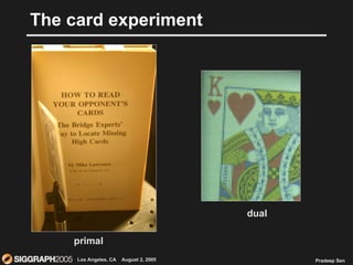
- 92. The card experiment book camera card projector primal
- 93. The card experiment primal dual
- 94. Overview of dual photography standard photograph from camera dual photograph from projector
- 95. Outline 1. Introduction to dual photography 2. Application to scene relighting 3. Accelerating acquisition 4. Conclusions
- 96. Helmholtz reciprocity light eye eye light I I I I primal dual scene projector photosensor primal
- 97. Helmholtz reciprocity projector photosensor projector photosensor scene light camera primal dual
- 98. Forming a dual image projector photosensor light camera scene primal dual C 0 C 1 C 2 C 3 C 4 C 5 C 6 C 7
- 99. Forming a dual image scene light camera dual C 0 C 1 C 2 C 3 C 4 C 5 C 6 C 7
- 100. Physical demonstration Projector was scanned across a scene while a photosensor measured the outgoing light photosensor resulting dual image
- 101. Related imaging methods Example of a “flying-spot” camera built at the dawn of TV (Baird 1926) Scanning electron microscope Velcro ® at 35x magnification, Museum of Science, Boston
- 102. Dual photography for relighting p q n m projector camera dual camera dual projector 4D projector photosensor primal scene dual
- 103. Mathematical notation scene p q n m projector camera primal P pq x 1 C mn x 1 T mn x pq
- 104. Mathematical notation = primal P pq x 1 C mn x 1 T mn x pq
- 105. = pq x 1 mn x 1 Mathematical notation 1 0 0 0 0 0 T mn x pq
- 106. = pq x 1 mn x 1 Mathematical notation 0 1 0 0 0 0 T mn x pq
- 107. = pq x 1 mn x 1 Mathematical notation 0 0 1 0 0 0 T mn x pq
- 108. = Mathematical notation little interreflection -> sparse matrix many interreflections -> dense matrix T mn x pq P pq x 1 C mn x 1
- 109. ? Mathematical notation T = mn x pq primal space dual space = pq x mn P pq x 1 C mn x 1 C mn x 1 P pq x 1 j i i j T ij T T ji T = T T T = T ji ij
- 110. Definition of dual photography = primal space dual space = T mn x pq pq x mn T T T mn x pq mn x 1 C pq x 1 P pq x 1 P mn x 1 C
- 111. Sample results primal dual
- 112. Sample results primal dual
- 113. Scene relighting Knowing the pixel-to-pixel transport between the projector and the camera allows us to relight the scene with an arbitrary 2D pattern primal dual
- 114. Photosensor experiment = primal space dual space = T mn x pq pq x 1 P mn x 1 C C T 1 x pq T 1 x pq pq x 1 P pq x 1 T T C
- 115. 2D relighting videos Relighting book scene with animated patterns Relighting box with animated pattern
- 116. Relighting with 4D incident light fields 2D 4D 6D Transport
- 117. From Masselus et al. SIGGRAPH ‘03 Relighting with 4D incident light fields
- 118. Relighting with 4D incident light fields 2D 4D 6D Transport
- 119. Relighting with 4D incident light fields 2D 4D 6D Transport
- 120. Acquisition of transport from multiple projectors cannot be parallelized Acquisition of transport using multiple cameras can ! Advantages of our dual framework
- 121. “ Multiple” cameras with mirror array
- 122. Relighting video Relighting scene from multiple light positions using mirror array
- 123. Accelerating acquisition Brute-force pixel scan is very slow! (10 6 patterns for standard projector) We present a hierarchical, adaptive algorithm in our paper to parallelize this process
- 124. Adaptive acquisition video Demonstration of adaptive algorithm acquiring cover image
- 125. Parallelize to accelerate acquisition = pq x 1 mn x 1 0 1 0 0 0 0 0 0 0 0 1 0 0 1 0 0 1 0 We can extract columns of T in parallel if no camera pixel sees contribution from both pixels at once Our algorithm adaptively finds which pixels do not conflict with each other to display them in parallel T mn x pq P C
- 126. Overview of adaptive algorithm Start with floodlit projector, recursively subdivide into 4 child blocks until pixel level Blocks in the projector are scheduled at the same time if there is no conflict in the camera Blocks that do not have any contribution are culled away Store the energy in the last point of the hierarchy where it was last measured Details in the paper…
- 127. Results Size(MB) Time (min) Size (MB) Time(min) Acceleration 5.4e6 1.6e4 272 142 115x 3.7e6 1.1e4 179 14 751x 1.6e6 1.2e4 56 19 629x 1.4e6 1.2e4 139 15 797x 1.1e8 5.2e5 6.7e3 1.8e3 296x Pixel scan Hierarchical x80
- 128. Practical challenges and limitations Projector’s dark pixels are not fully dark Result: reduces our SNR Solution: use high-contrast projector, subtract out dark-level Camera has Bayer filters on pixels Result: colors are desaturated if projector illuminates small portion of the CCD Solution: normalize energy with flood-lit image Little light transport from projector to camera Result: hierarchical scheme quits early, resulting in blurry images Solution: get more light from projector to camera – increase aperture, lengthen exposure
- 129. Future work Acquire 6D data set using camera array Relight with real 4D incident illumination captured by camera array Explore further properties of T matrix Combine dual photography with other techniques for efficient acquisition of full 8D reflectance function
- 130. Conclusions Dual photography is a novel imaging technique that allows us to interchange the camera and the projector Dual photography can accelerate acquisition of the 6D transport for relighting with 4D incident light fields We developed an algorithm to accelerate the acquisition of the transport matrix for dual photography
- 131. The card experiment book camera card projector primal
- 132. The card experiment primal dual
- 133. Hierarchical construction of T primal dual
- 134. Photosensor experiment = primal space dual space = T mn x pq pq x 1 P mn x 1 C C T 1 x pq T 1 x pq pq x 1 P pq x 1 T T C
- 135. Example X X X X X X O O 8 x 8 pixel projector projected patterns
- 136. Example In this example, it took 21 patterns to perform acquisition It would take 64 with brute-force scan Without conflicts, we need: num. levels x 4 + 1 In this case: log 64 x 4 + 1 = 13 4 projected patterns
- 137. Projector dark level Unfortunately, projector “off” pixels are not completely dark. They emit light! Correspondence with the number of pixels that are on, and with the distance from the nearest lit pixel. Projector used in the experiments was quoted approx 2000:1 contrast ratio (full on/off).
- 138. Camera Bayer Pattern Digital cameras do not typically sample in all colors at every pixel. They sample based on a color pattern called a Bayer pattern. When the projector illuminates small regions as seen by the camera, often the color can be mismatched To fix this, normalize energy with fully-lit image
- 139. Results Size(TB) Time (days) Size (MB) Time(min) #patterns 5.4 10.9 272 136 3397 3.7 7.3 179 14 352 1.6 8.3 56 19 501 1.4 8.3 139 15 369 114 362 6,675 1,761 19,140 Pixel scan Hierarchical algorithm x80
- 140. Computational Illumination: Programmable 4D Illumination Field + Time + Wavelength Presence or Absence, Duration, Brightness Flash/No-flash (matting for foreground/background) Light position Relighting: Programmable dome Shape enhancement: Multi-flash for depth edges Light color/wavelength Spatial Modulation Dual Photography, Direct/Global Separation, Synthetic Aperture Illumination Temporal Modulation TV remote, Motion Tracking, Sony ID-cam, RFIG Exploiting (uncontrolled) natural lighting condition Day/Night Fusion, Time Lapse, Glare
- 141. Visual Chatter in the Real World Shree K. Nayar Computer Science Columbia University With: Guru Krishnan, Michael Grossberg, Ramesh Raskar Eurographics Rendering Symposium June 2006, Nicosia, Cyprus Support: ONR
- 142. source surface P Direct and Global Illumination camera A A : Direct B B : Interrelection C C : Subsurface D participating medium D : Volumetric translucent surface E E : Diffusion
- 143. Shower Curtain: Diffuser Direct Global
- 144. Related Work Shape from Interreflections (Nayar et. al., ICCV 90) (Seitz et. al., ICCV 05) Inverse Light Transport (Sen et. al., Siggraph 05) T Dual Photography
- 145. Fast Separation of Direct and Global Images Create Novel Images of the Scene Enhance Brightness Based Vision Methods New Insights into Material Properties
- 146. Compute Direct and Global Images of a Scene from Two Captured Images Create Novel Images of the Scene Enhance Brightness Based Vision Methods New Insights into Material Properties
- 147. Direct and Global Components: Interreflections surface i camera source direct global radiance j BRDF and geometry
- 148. High Frequency Illumination Pattern surface camera source fraction of activated source elements + i
- 149. High Frequency Illumination Pattern surface fraction of activated source elements camera source + - i
- 150. Separation from Two Images direct global
- 152. Other Global Effects: Subsurface Scattering translucent surface camera source i j
- 153. Other Global Effects: Volumetric Scattering surface camera source participating medium i j
- 154. Diffuse Interreflections Specular Interreflections Volumetric Scattering Subsurface Scattering Diffusion
- 155. Scene Direct Global
- 156. F G C A D B E A: Diffuse Interreflection (Board) B : Specular Interreflection (Nut) C : Subsurface Scattering (Marble) D : Subsurface Scattering (Wax) E : Translucency (Frosted Glass) F : Volumetric Scattering (Dilute Milk) G : Shadow (Fruit on Board) Verification
- 157. Verification Results 0 0.2 0.4 0.6 0.8 1 3 5 7 9 11 15 19 23 27 31 35 39 43 47 p C D F E G B A Checker Size marble D F E G B A 0 20 40 60 0.1 0.2 0.3 0.4 0.5 0.6 0.7 0.8 0.9 1.0 Fraction of Activated Pixels
- 159. V-Grooves: Diffuse Interreflections concave convex Psychophysics: Gilchrist 79, Bloj et al. 04 Direct Global
- 160. Mirror Ball: Failure Case Direct Global
- 161. Real World Examples: Can You Guess the Images?
- 162. Eggs: Diffuse Interreflections Direct Global
- 163. Wooden Blocks: Specular Interreflections Direct Global
- 164. Novel Images
- 165. Variants of Separation Method Shadow of Line Occluder Shadow of Mesh Occluders Coded Structured Light Shifted Sinusoids
- 166. Stick Building Corner Shadow 3D from Shadows: Bouguet and Perona 99 direct global
- 167. Building Corner Direct Global
- 168. Shower Curtain: Diffuser Shadow Mesh direct global
- 169. Shower Curtain: Diffuser Direct Global
- 171. Kitchen Sink: Volumetric Scattering Volumetric Scattering : Chandrasekar 50, Ishimaru 78 Direct Global
- 172. Novel Image
- 173. Peppers: Subsurface Scattering Direct Global
- 174. Novel Images
- 175. Real or Fake ? Direct Global R F R F R F
- 176. Tea Rose Leaf Leaf Anatomy: Purves et al. 03 Direct Global
- 177. Translucent Rubber Balls Direct Global
- 178. Scene Direct Global Marble: When BSSRDF becomes BRDF Subsurface Measurements: Jensen et al. 01, Goesele et al. 04 1 4 Resolution 1 1 6 1 2
- 179. Hand Skin: Hanrahan and Krueger 93, Uchida 96, Haro 01, Jensen et al. 01, Igarashi et al. 05, Weyrich et al. 05 Direct Global
- 180. Hands Afric. Amer. Female Chinese Male Spanish Male Direct Global Afric. Amer. Female Chinese Male Spanish Male Afric. Amer. Female Chinese Male Spanish Male
- 181. Separation from a Single Image
- 182. Face Direct Global Sum
- 183. Skin Tone Control Skin Color and Lipids: Tsumura et al. 03
- 184. Blonde Hair Hair Scattering: Stamm et al. 77, Bustard and Smith 91, Lu et al. 00 Marschner et al. 03 Direct Global
- 185. Hair: Bidirectional Texture Function Direct Global Hair
- 186. Pebbles: 3D Texture Direct Global
- 187. Pebbles: Bidirectional Texture Function Direct Global Pebbles
- 188. Pink Carnation Spectral Bleeding: Funt et al. 91 Global Direct
- 190. Summary Fast and Simple Separation Method Wide Variety of Global Effects No Prior Knowledge of Material Properties Implications: Generation of Novel Images Enhance Computer Vision Methods Insights into Properties of Materials
- 191. + = + = + = + = + = + + = = + = www.cs.columbia.edu/CAVE + = + =
- 192. Computational Illumination: Programmable 4D Illumination Field + Time + Wavelength Presence or Absence, Duration, Brightness Flash/No-flash (matting for foreground/background) Light position Relighting: Programmable dome Shape enhancement: Multi-flash for depth edges Light color/wavelength Spatial Modulation Dual Photography, Direct/Global Separation, Synthetic Aperture Illumination Temporal Modulation TV remote, Motion Tracking, Sony ID-cam, RFIG Exploiting (uncontrolled) natural lighting condition Day/Night Fusion, Time Lapse, Glare
- 193. Day of the year Time of day
- 194. The Archive of Many Outdoor Scenes (AMOS) Images from ~1000 static webcams, every 30 minutes since March 2006. Variations over a year and over a day Jacobs, Roman, and Robert Pless, WUSTL CVPR 2007,
- 195. Analysing Time Lapse Images PCA Linear Variations due to lighting and seasonal variation Decompose (by time scale) Hour: haze and cloud for depth . Day: changing lighting directions for surface orientation Year: effects of changing seasons highlight vegetation Applications: Scene segmentation. Global Webcam localization. Correlate timelapse video over a month from unknown camera with: sunrise + sunset (localization accuracy ~ 50 miles) Known nearby cameras (~25 miles) Satellite image (~15 miles) Mean image + 3 components from time lapse of downtown st. louis over the course of 2 hours
- 196. 2 Hour time Lapse in St Louis: Depth from co-varying regions
- 197. Surface Orientation False Color PCA images
- 198. Image Fusion for Context Enhancement and Video Surrealism Adrian Ilie Ramesh Raskar Jingyi Yu
- 199. Dark Bldgs Reflections on bldgs Unknown shapes
- 200. ‘ Well-lit’ Bldgs Reflections in bldgs windows Tree, Street shapes
- 201. Background is captured from day-time scene using the same fixed camera Night Image Day Image Context Enhanced Image http://web.media.mit.edu/~raskar/NPAR04/
- 202. Factored Time Lapse Video Factor into shadow, illumination, and reflectance. Relight, recover surface normals, reflectance editing. [Sunkavalli, Matusik, Pfister, Rusinkiewicz], Sig’07
- 204. Computational Illumination: Programmable 4D Illumination Field + Time + Wavelength Presence or Absence, Duration, Brightness Flash/No-flash (matting for foreground/background) Light position Relighting: Programmable dome Shape enhancement: Multi-flash for depth edges Light color/wavelength Spatial Modulation Dual Photography, Direct/Global Separation, Synthetic Aperture Illumination Temporal Modulation TV remote, Motion Tracking, Sony ID-cam, RFIG Exploiting (uncontrolled) natural lighting condition Day/Night Fusion, Time Lapse, Glare
Editor's Notes
- #5: Like wristwatches?
- #27: http://www.flickr.com/photos/pgoyette/107849943/in/photostream/
- #40: New techniques are trying decrease this distance using a folded optics approach. The origami lens uses multiple total internal reflection to propagate the bundle of rays.
- #42: CPUs and computers don’t mimic the human brain. And robots don’t mimic human activities. Should the hardware for visual computing which is cameras and capture devices, mimic the human eye? Even if we decide to use a successful biological vision system as basis, we have a range of choices. For single chambered to compounds eyes, shadow-based to refractive to reflective optics. So the goal of my group at Media Lab is to explore new designs and develop software algorithms that exploit these designs.
- #43: Current explosion in information technology has been derived from our ability to control the flow of electrons in a semiconductor in the most intricate ways. Photonic crystals promise to give us similar control over photons - with even greater flexibility because we have far more control over the properties of photonic crystals than we do over the electronic properties of semiconductors.
- #44: Changes in the index of refraction of air are made visible by Schlieren Optics. This special optics technique is extremely sensitive to deviations of any kind that cause the light to travel a different path. Clearest results are obtained from flows which are largely two-dimensional and not volumetric. In schlieren photography, the collimated light is focused with a lens, and a knife-edge is placed at the focal point, positioned to block about half the light. In flow of uniform density this will simply make the photograph half as bright. However in flow with density variations the distorted beam focuses imperfectly, and parts which have focussed in an area covered by the knife-edge are blocked. The result is a set of lighter and darker patches corresponding to positive and negative fluid density gradients in the direction normal to the knife-edge.
- #45: Full-Scale Schlieren Image Reveals The Heat Coming off of a Space Heater, Lamp and Person
- #49: 4 blocks : light, optics, sensors, processing, (display: light sensitive display)
- #50: 4 blocks : light, optics, sensors, processing, (display: light sensitive display)
- #62: But what if the user is not wearing the special clothing. Can we still understand the gestures using a simple camera? The problem is that in a cluttered scene, it is often difficult to do image processing.
- #84: But what if the user is not wearing the special clothing. Can we still understand the gestures using a simple camera? The problem is that in a cluttered scene, it is often difficult to do image processing.
- #92: Good afternoon and thank you for attending our talk entitled “Dual Photography”.
- #95: I will start off by giving you a quick overview of our technique. Suppose you had the scene shown which is being imaged by a camera on the left and is illuminated by a projector on the right. If you took a picture with the camera, here’s what it would look like. You can see the scene is being illuminated from the right, from the position of the projector located off camera. Dual photography allows us to virtually exchange the positions of the camera and the projector, generating this image. This image is synthesized by our technique. We never had a camera in this position. You can see that the technique has captured shadows, refraction, reflection and other global illumination effects.
- #96: In this talk I will start off by discussing how dual photography works. I will give a motivation For dual photography by applying it to the problem of scene relighting, and show that it can be Used to greatly accelerate the acquisition of the data needed. I will then talk about an algorithm We developed to accelerate the acquisition of the light transport needed to perform dual photography And I will end with some conclusions.
- #97: Dual photography is based on the principle of Helmholtz reciprocity. Suppose we have a ray leaving the light with intensity I and scattering off the scene towards the eye with a certain attenuation. Let’s call this the primal configuration. In the dual configuration, the positions of the eye and the light are interchanged. Helmholtz reciprocity says that the scattering is symmetric, thus the same ray in the opposite direction will have the same attenuation.
- #102: This photocell configuration might remind us of imaging techniques. For example, in the early days of television a similar method was use to create one of the first TV cameras. Known as a “flying-spot” camera, a beam of extremely bright light would scan the scene and a bank of photosensors would measure the reflected light. The value measured at these sensors would be immediately sent out via closed-circuit to television sets whose electron beam was synchronized with the beam of light. Thus they drew out the image as it was being measured by the Photosensors. This allowed for the creation of a television system that did not have to have a means to store “frames” of video. Another related applications. Finally scanning electron microscopes (and other scanned beam systems for that matter) can be thought of as employing the principle of dual photography. Thus while some of these applications might be new, what is new is the framework that establishes dual photography in this manner and gives us insights to possible applications such as relighting as we shall see in a moment.
- #103: Suppose we had the scene shown and we illuminated it with a projector from the left and imaged it with a camera on the right. Now the pixels of the projector and the camera form solid angles in space whose size depends on the resolution of each. Lets assume a resolution of pxq for the projector and mxn for the camera. What dual photography does is transform the camera into a projector and the projector into a camera. Note that the properties of the new projector (such as position, field-of-view, and resolution) are the same as that of the old camera, and vice versa. We call this the dual configuration. In this work we shall see that it is possible to attain this dual configuration by making measurements only in the original primal configuration. We will do this by measuring the light transport between individual pixels of the projector to individual pixels of the camera. Because there are 2D pixels in the projector and 2D pixels in the camera, this light transport is a 4D function. Now lets see how we can represent this system with mathematical notation.
- #104: Fortunately, the superposition of light makes this a linear system and so we can represent this setup with a simple linear equation. We can represent the projected pattern as a column vector of resolution pq x 1 and likewise we can represent the camera as a column vector of resolution mn x 1. This means that the 4-D light transport function that specifies the transport of light from a pixel in the projector to a pixel in the camera can be represented as a matrix of resolution mn x pq.
- #105: If we put these elements together, we can see that it forms a simple linear equation. Here we apply the projected pattern at vector P to the transport matrix, which we call the “T” matrix in the paper and we get a result at vector C, which is our resulting camera image for that projector pattern. I must mention that if T is properly measured, it will contain all illumination paths from the projector to the camera, including multiple bounces, subsurface scattering, and other global illumination contributions which are often desireable. At this point, let’s gain an intuition as to the composition of T. What does this matrix look like?
- #106: We can gain insight into this by illuminating patterns at the projector that have only a single pixel turned on as shown here. We can see if we apply this vector at P, it will address a single column of T which will be output at C.
- #107: This is true for each vector P with a single pixel turned on; they will extract a different column of T.
- #108: Thus we can see that the columns of T are composed of the images we would take at C with a different pixel turned on at the projector.
- #109: So this is the way light flows in our primal configuration…
- #110: We’re going to put primes above the P and C vectors to indicate that they are in the primal space. So what will happen when we go to the dual space and interchange the roles of the camera and the projector? Now light will be emitted by the camera and photographed by the projector. So this gives us the linear equation shown at the bottom. It is obviously still a linear system, except that now light leaves the camera is transformed by this new transport matrix (let’s call it T2) and results in an image at the projector. Note that the dimensions of the camera and the projector stay the same. So dimensional analysis indicates that the dimension of T2 is now pq x mn. The key observation of dual photography is that the new matrix T2 is related to the original T. We can see that if we look at the transport for a particular pixel of the projector to a particular pixel of the camera. Let’s look at the transport from pixel “j” of the projector to pixel “i” of the camera. The transport between this pair is specified by a single element in the T matrix, in this case element Tij. Now let’s look at the same pixels in at the dual configuration with the camera emitting light and the projector capturing it. The pixel Of interest in the camera is still pixel I and the pixel of interest in the projector is still j. In this case the element that relates These two is T2ji. Dual Photography is made possible by Helmholtz reciprocity which can be shown to indicate that the pixel To pixel transport is symmetric, that is the transport will be the same whether the light is leaving the projector pixel and going to The camera pixel, or going from the camera pixel to the projector pixel. Thus we can write that T2ji = Tij. This means that T2 is simply the transpose the original T.
- #111: Thus we can define “Dual Photography” as the process of transposing this transport matrix to generate pictures from the point of view of the projector as illuminated by the camera. To create a dual image, we must first capture the transport matrix T between the projector and camera in the primary configuration. As I indicated earlier, lighting up individual pixels of the projector extract single columns of the T matrix, and if we do that for all the columns T can be acquired in that manner. We shall talk about an acceleration technique later in the talk. Again, dual photography is based only on the fact that the pixel-to-pixel transport is symmetric. We formally prove this in the Appendix of the paper.
- #112: Before we continue, let’s take a look at some initial results taken by our system. Here we show the primal image of a set of famous graphics objects. Here the projector is to the right. If we take a look at the dual image, we can see that we are now looking at these objects face on and the illumination is coming in from where the camera used to be. Note that the shading on all the objects is correct.
- #113: In this next example, we have a few objects viewed from above by the camera. The projector is in front of them and forms a fairly grazing angle with the floor So it is gray. If we look at the dual image, we can see the objects from in front being lit from above. Note that the floor is now brighter because the new light source (which was the original camera) is viewing it from a more perpendicular direction. Also see for example that the shadow on the horse in the dual image corresponds To the portion of the horse that the pillar is occluding. So in some ways, what we have here is a real-life shadow map, where the primal is the shadow map fro the dual. One thing I really like about this image is that you can see detail in the dual that is not visible in the primal. Take a look at the concentric rings in the detail at the base Of the pillar. This detail is simply not visible in the primal because of the angle but is very clear in the dual. Also the detail of the lions heads is more clear in the dual than in the primal.
- #114: We observe that since we have the complete pixel-to-pixel transport, we can relight either the primal or dual images with a new 2D projector pattern.
- #115: As far as the equations are concerned, what the photosensor is doing is integrating all of the values of the C vector into a single scalar value. Assume that this integration is being done uniformly across the field-of-view of the photosensor. So this is our new primal equation. Since the T matrix is no longer relating a vector to a vector, it collapses into a row vector of dimensions pq x 1 as shown here. We can measure this T vector in the same manner, by illuminating single pixels at the projector to extract the elements of T. If we transpose this vector into a column vector, we get the dual configuration, meaning the photograph taken by the projector and illuminated by the photocell. Here the incident illumination provided by c cannot be spatially varying since C is a scalar. This means that our light is a Uniform scaling of T. The picture shown here is an image that we acquired using a photocell shown and a projector.
- #116: I will now show some videos that show the projector patterns animating.
- #135: As far as the equations are concerned, what the photosensor is doing is integrating all of the values of the C vector into a single scalar value. Assume that this integration is being done uniformly across the field-of-view of the photosensor. So this is our new primal equation. Since the T matrix is no longer relating a vector to a vector, it collapses into a row vector of dimensions pq x 1 as shown here. We can measure this T vector in the same manner, by illuminating single pixels at the projector to extract the elements of T. If we transpose this vector into a column vector, we get the dual configuration, meaning the photograph taken by the projector and illuminated by the photocell. Here the incident illumination provided by c cannot be spatially varying since C is a scalar. This means that our light is a Uniform scaling of T. The picture shown here is an image that we acquired using a photocell shown and a projector.
- #202: http://web.media.mit.edu/~raskar/NPAR04/