SlideShare a Scribd company logo
Application-to-Architecture
Mapping
4541.633A SoC Design Automation
School of EECS
Seoul National University
Introduction
Introduction
• System design methodology
– Traditional method
• Mostly bottom-up
• Given application and constraints
– First assemble HW components
– Then develop SW
• What if it fails to meet the specification?  reassemble
– HW-SW codesign
• Mostly top-down
• Given application, constraints, and simple architectural
assumption
• Partition the application into HW and SW
• Synthesize from the partitions
HW-SW Codesign
HW-SW Codesign
• Typical HW-SW codesign flow
System Implementation
SW
HW part
Interface
SW part
Internal Rep.
System Specification
Analysis
HW-SW Partitioning
SW
Generation
Interface
Synthesis
HW
Synthesis
System Simulation
compilation
System Integration
HW-SW Codesign
• Polis
– F. Balarin, et al., Hardware-Software Co-Design of
Embedded Systems: The Polis Approach, Kluwer
Academic Publishers, 1997.
– A design environment for control-dominated embedded
systems
– MoC: CFSM (Co-design Finite State Machine)
• Globally asynchronous/locally synchronous
– Formal verification or simulation for the analysis of a
system at the behavioral level
– It can generate C-code and HDL code
– Weak points
• Only CFSM: control-dominated application
• Does not support estimation technique for complex
processor models
• Does not support multiple hardware and software
partitioning
HW-SW Codesign
– Overall flow
formal languges
(Esterel)
translators
CFSMs
partitioning
partitioned CFSMs
HW synthesis
SW synthesis interface synthesis
BLIF
optimized hardware
C code
OS synthesis
HW interface
logic synthesis
integration
S-graph
scheduler
template +
timing
constraints
simulation
formal
verification
verification
intermediate
format
translator
HW-SW Partitioning
HW-SW Partitioning
• Partitioning system functionality into
– Application specific hardware and
– Software executing on one (or more) processor(s)
• Partitioning problem
– Find minimum cost HW-SW combination satisfying
constraints
• Cost = f (HW area, HW delay, SW size, SW time, interface
size, interface delay, power, ... )
– Need efficient and accurate performance, cost, power
estimation models
– Need efficient partitioning algorithms
• Greedy method
• Simulated annealing
• Kernighan-Lin
• Integer linear programming
• Global criticality/local phase
• Manual
• ...
HW-SW Partitioning
• ILP-based approach
– R. Niemann and P. Marwedel,
“Hardware/software partitioning
using integer programming,”
Proc. ED&TC, Mar. 1996.
– Concurrent partitioning,
scheduling, and sharing
– Integer linear programming
– Minimize design cost with
performance & resource
constraints
VHDL
C code VHDL code
retargetable
compilation
high-level
synthesis
SW costs HW costs
partitioning
(solve ILP)
cluster SW nodes
retargetable
compilation
SW costs
HW-SW Partitioning
• Global criticality/local phase
– A. Kalavade and E. A. Lee, “A global criticality/local
phase driven algorithm for the constrained
hardware/software partitioning problem," Proc.
Codes/CASHE, Sept. 1994, pp. 42-48.
– Global Criticality/Local Phase (GCLP)
• GC
– Global time-criticality (feasibility)
– Node-invariant
• LP
– Classify each node into three phases: extremity, repeller,
normal
– Determine mapping and start time for each node
– Quadratic complexity
– Task/process level of granularity
HW-SW Partitioning
– Objective function
• Not hardwired
• Selected at each step according to GC & LP
HW-SW Partitioning
– Global criticality
• Probability that an unscheduled node (in U) should be
implemented in HW to meet latency constraint
• Algorithm
1. Estimate H nodes to move to HW according to priority (more
performance, less area --> gets higher priority) so that the
remaining SW nodes can be executed within Tremaining
2. Compute actual finish time
3. If not feasible, go to 1.
4. Compute GC=(size of H)/(size of U),
size: number of elementary operations
HW-SW Partitioning
– Local phase 1: extremity
• Determine extremity sets EXs and EXh
– Local phase 2: repellers
• Software repeller property
– Bit-level instruction mix, precision level
• Hardware repeller property
– Memory-intensive instruction mix, table-lookup instruction
mix
HW-SW Partitioning
– Compute D
• If i  (EXs  EXh), -0.5<D<0.5 depending on the level of
extremity (more negative if HW is preferred)
• Else if repeller, -0.5<D<0.5 depending on the repeller value
(more negative if HW is preferred)
• For a normal node, D=0
HW-SW Partitioning
– Experimental results
• ILP: several hours
• GCLP: order of seconds
• Good solution: low HW area and high DSP utilization
– HA: hardware area, SA: software area, Util: DSP utilization
HW-SW Partitioning
• Implementation-bin selection
– A. Kalavade and E. A. Lee, "The extended partitioning
problem: hardware/software mapping and
implementation-bin selection," Proc. of the 6th
International Workshop on Rapid. Systems Prototyping,
1995.
– Mapping and implementation-bin selection (MIBS)
HW-SW Partitioning
– Algorithm
• Perform GCLP-based HW-SW partitioning
– Use median values for the HW cost/time
– Implementation-bin selection is applied to HW only but it is
also applicable to SW
• Bin Fraction Curve (BFC)
– Fraction of free nodes that need to be mapped to their L bins
• Bin Sensitivity Curve (BSC)
– Slopes of the BFC
HW-SW Partitioning
– Algorithm
• Computation of BFC
HW-SW Partitioning
– Algorithm
• Weighted bin sensitivity curve
HW-SW Partitioning
– Results
mapped to L bins mapped to median implementation bins
Platform-Based Design
• Trend in System-on-Chip (SoC) design
– Larger design space
• Exponentially growing transistor counts (Moore's law)
• Ever increasing complexity of applications
• Multi-functional and multi-standard
– More flexibility, higher performance, lower energy, ...
– Shorter Time-to-Market
– Need more efficient design methodology
0.001
0.01
0.1
1
10
100
1000
10000
M
Logic
Transistors/Chip
0.01
0.1
1
10
100
1000
10000
100000
1981
1983
1985
1987
1989
1991
1993
1995
1997
1999
2001
2003
2005
2007
2009
K
Transistors/Staff-Month
Complexity
Productivity
Complexity
58%/yr growth rate
Productivity
21%/yr growth rate
Complexity
Productivity
• Reuse of
– Cell (standard cell)
– IP
– Architecture (platform) --> platform-based design
– IC (reconfigurability)
Memory
Video RAM
I/O
Host interface
DSP core 1
(D950)
Modem
DSP core 2
(D950)
Sound
ASIP 1
Master
Control
ASIP 2
Memory
Controller
ASIP 3
Bit
Manipulation
ASIP 4
(VLIW DSP)
Programmable video operations,
standard extensions
I/O
S interface
Glue logic
A/D
&
D/A
High-speed HW
Video operations for
DCT, IDCT, motion estimation
Single chip
videophone
(H.263)
Platform-Based Design
• Platform and derivative design
Hard IP
Soft IP
Others
EDA
Integrator
Application specific integration platform
EDA
Tools
EDA
Tools
Derivative
Platform
Design-Space
Exploration
Platform
Specification
Architectural Space
Application Space
Application Instance
Platform Instance
System
Platform
Large
Design-Space
Exploration
Application Space
Application Instance
Architectural Space
Platform Instance
Conventional Design Platform-Based Design
Platform-Based Design
• Design-space exploration
Platform-Based Design
• Taxonomy of SoC platforms
– Full-Application Platforms
• Philips Nexperia
• TI OMAP (Open Multimedia Application Platform)
• ARM PrimeXsys
• Intel Xscale Architecture
– Processor-centric platform
• Improv Jazz
• Tensilica Xtensa
– Communication-Centric platform
• ARM AMBA bus architecture
• Sonics mNetwork
• IBM CoreConnect
– Fully Programmable Platform
• Altera Excalibur
• Xilinx Virtex-II Pro
Platform-Based Design
• Full-application platform
– Concentrates on full application
• Delivers comprehensive set of libraries hardware and
software
• Delivers several mapping and application examples
– Texas Instruments OMAP
Application domain: 2.5G/3G Wireless mobile devices
– Philips Nexperia
Application domain: Digital Video, Digital Audio,
Mobile Communications
Platform-Based Design
• Texas instrument OMAP1610
– Dual processor core
• ARM926, TI DSP
• Up to 200MHz
– Multimedia cores
• 2D Graphics accelerator
• LCD controller
• MMC interface
• USB interface
– Wireless supports
• Bluetooth
• 3G
Platform-Based Design
• Nexperia platform
Scalable VLIW Media
Processor:
• 100 to300+ MHz
• 32-bit or64-bit
Nexperia™
System Buses
• 32-128 bit
General-purpose Scalable RISC
Processor
• 50 to300+ MHz
• 32-bit or64-bit
LibraryofDevice
IP Blocks
• Image coprocessors
• DSPs
• UART
• 1394
• USB
…and more
TM-xxxx
D$
I$
TriMedia CPU
DEVICE IP BLOCK
DEVICE IP BLOCK
DEVICE IP BLOCK
.
.
.
DVP SYSTEMSILICON
PI
BUS
SDRAM
MMI
DVP
MEMORY
BUS
DEVICE IP BLOCK
PRxxxx
D$
I$
MIPS CPU
DEVICE IP BLOCK
.
.
.
DEVICE IP BLOCK
PI
BUS
TriMedia™
MIPS™
Platform-Based Design
• Nexperia software architecture
– Scalable from low-end to high-end
– Consistent API (on MIPS or TriMedia)
– Single Streaming Architecture for MIPS and TriMedia
– Aligned to Nexperia™ DVP (Digital Video Platform) HW
architecture and IP blocks
– Operating system independent software layers
• OS abstraction libray
• Supports Linux, pSOS, Windows CE
– Re-use of software components on any instance of the
platform
Platform-Based Design
• Processor-centric platform
– Application Specific Instruction Set processor
• Configure processor pipeline
• Generate complete software development environment
– Tensilica Xtensa
Option: manually
refine configuration
Original
C/C++
Code
Evaluates
millions of
possible
extensions:
• SIMD
operations
• operator fusion
• parallel
execution
Designer
selects “best”
configuration
Run
XPRES
Compiler
int main()
{
int i;
short c[100];
for (i=0;i<N/2;i++)
{
Xtensa
Processor
Generator
Tuned
Software Tools
Processor
Hardware
ALU
DSP
OCD
Timer
FPU
Register File
Cache
Platform-Based Design
• Configuration of Xtensa
External Interface
Base ISA Feature
Configurable Function
Optional Function
User Defined Features (TIE)
Optional & Configurable
User Defined
Queues and Wires
JTAG Extended Instruction
Align, Decode,
Dispatch
Xtensa
Processor
Interface
Control
Write
Buffer
Xtensa
Local
Memory
Interface
TRACE Port
JTAG Tap Control
On Chip Debug
User
Defined
Execution
Units and
Interfaces
Instruction
Decode/Dispatch
Base ALU
Floating Point
Vectra DSP
MAC 16 DSP
MUL 16/32
User
Defined
Register
Files
Instruction Fetch / PC
Data
Load/Store
Unit
Data ROMs
Data RAMs
Data
Cache
Data
MMU
User
Defined
Execution
Units
User
Defined
Register
Files
Vectra
DSP
Base Register
File
User Defined
Execution Unit
Vectra DSP
Processor Controls
Interrupt Control
Data Address
Watch Registers
Instruction Address
Watch Registers
Timers
Used Defined Data
Load/Store Units
Instruction ROM
Instruction RAM
Instruction
Cache
Instruction
MMU
PIF
Exception Support
Exception Handling
Registers
Trace
Interrupts
Platform-Based Design
• Communication-centric platform
– Concentrates on communication back-bone (or On-chip
Interconnection)
- Delivers communication framework (plus generic
peripherals)
– Sonics SiliconBackplane , PALMCHIP CoreFrame
Platform-Based Design
• Fully programmable platform
– Concentrates on reconfigurability
• Delivers processor plus programmable logic
– Xilinx Virtex-II Pro (Platform FPGA)
– Altera Excalibur (Platform FPGA)
Platform-Based Design
• Xilinx Virtex-II Pro
– PowerPC uP (400MHz)
– FPGA logics
– Internal RAM
– Serial transceiver
– XtremeDSP functions
– Digitally controlled impedance
Platform-Based Design
• Altera Excalibur
ARM922T
Cache
MMU
AHB1
Interrupt
Controller
Watchdog
Timer
SDRAM
Controller
Single Port
SRAM0
Single Port
SRAM1
Dual Port
SRAM0
Dual Port
SRAM1
AHB2
AHB1-
AHB2
Bridge
EBI UART
Timer
(Configuration)
Register
Flash Rom SRAM
Master
Slave
Slave
Master
Stripe-to-PLD
Bridge
PLD-to-Stripe
Bridge
PLD
1/2 PLL1
1/4 PLL1
Configuration
Logic
Master
Platform-Based Design
• System design flow
Mapping
Application
HW
synthesis
HW
Constraints
Architecture
SW
synthesis
SW
Mapping
results
IF
synthesis
Estimation of
performance,
area, and
power
in HW and SW
Application-to-Architecture Mapping
for(i = 0; i < 18; i++) {
s = (mpfloat)0.0f;
k = 0;
do {
s += X[k] * v[k];
s += X[k+1] * v[k+1];
s += X[k+2] * v[k+2];
s += X[k+3] * v[k+3];
s += X[k+4] * v[k+4];
s += X[k+5] * v[k+5];
k += 6;
} while(k < 18);
v += 18;
ISCALE(s);
t[i] = s;
}
/* correct the transform into the 18x36 IMDCT we need */
/* 36 muls */
for(i = 0; i < 9; i++) {
x[i] = t[i+9] * Granule_imdct_win[gr->block_type][i];
ISCALE(x[i]);
x[i+9] = t[17-i] * Granule_imdct_win[gr->block_type][i+9];
ISCALE(x[i+9]);
x[i+18] = t[8-i] * Granule_imdct_win[gr->block_type][i+18];
ISCALE(x[i+18]);
x[i+27] = t[i] * Granule_imdct_win[gr->block_type][i+27];
ISCALE(x[i+27]);
}
Application in C
Platform architecture
Application-to-Architecture Mapping
• Y-chart approach
– B. Kienhuis, E. Deprettere, K. Vissers, P. van der Wolf,
"An approach for quantitative analysis of application-
specific dataflow architectures," Proc. ASAP'97, 1997.
Mapping
Application Architecture
Performance
numbers
Performance
analysis
Application-to-Architecture Mapping
– Abstraction pyramid
• A. Kienhuis, Design Space Exploration of Stream-based
Datatow Architectures, Ph.D. Thesis, Delft University of
Technology, 1999.
Application-to-Architecture Mapping
– Design trajectory
Design approach using
Y-chart environment
Golden point design
(low-level ad hoc design)
Application-to-Architecture Mapping
– Stack of Y-chart
• Use different models at different levels of abstraction
Application-to-Architecture Mapping
– Mapping
• A crucial step in DSE to evaluate the performance of
different application-architecture combinations
• For smooth mapping
– Need a good match in data and operation types between the
corresponding model of architecture and model of
computation
Architecture Application
Model of architecture Model of computation
Mapping
match in
data/operation
type
Application-to-Architecture Mapping
– Model of computation (MoC)
• A formal representation of the operational semantics of
networks of functional blocks describing computations
• Well-known MoCs
– Discrete Events (DE)
– Finite State Machines (FSM)
– Process Networks (PN)
– Synchronous Data Flow (SDF)
– Synchronous/Reactive (SR)
• Many different MoCs for various application domains
• May need multiple MoCs for modeling an application
Application-to-Architecture Mapping
– Model of architecture (MoA)
• A formal representation of the operational semantics of
networks of functional blocks describing architectures
• It is for modeling an architecture instance of the
architecture template
• Architecture template
– A specification of a class of architectures in a parameterized
form
– Parameters are number of functional units, buffer size, bus
type, latency, etc.
• Architecture instance
– The result of assigning values to parameters of the
architecture template
Application-to-Architecture Mapping
• YAPI
– E. de Kock, G. Essink, P. van der Wolf, J.-Y. Brunel, W.
Kruijtzer, P. Lieverse, and K. Vissers, "YAPI: Application
Modeling for Signal Processing Systems," Proc. DAC,
2000.
– YAPI: Y-chart API
– Application modeling for signal processing systems
• For the reuse of signal processing applications
• For the mapping of signal processing applications onto
heterogeneous systems
– Kahn process network (KPN)
• Often used for modeling signal processing applications
• Concurrent processes communicate through
unidirectional first-in-first-out channels
– Blocking read
– Non-blocking write
• Deterministic
– A limitation of KPN
• Cannot model reactiveness such as user interaction, that is,
non-deterministic events
• Control flow models such as finite state machines are a
solution, but less suited for the implementation of
computationally intensive applications.
– To extend KPN with non-deterministic events
• Introduce a communication primitive (channel selection
primitive)
– YAPI separates the concerns of the application programmer
and the system designer.
– Implementation of YAPI
• In the form of a C++ run-time library
– Read(), write(), execute(), and select()
– The implementation of these functions is a concern of the system
designer (may be implemented in different ways).
Application-to-Architecture Mapping
– Architecture evaluation in YAPI
• VIDEOTOP application
– The top-level process network model
Channel selection to
be decoded
MPEG2
stream
ts: transport stream
pid: packet id
pes: packetized elementary stream
es: elementary stream
Application-to-Architecture Mapping
• Simulation to measure the workload
– Communication requirement
• The amount of data that is transferred between processes
– Computation requirement
• The amount of computation of processes
• From the result
– We know that the required communication bandwidth is
150MB/s
– We select initial architecture as input for a more detailed
mapping and performance analysis
Application-to-Architecture Mapping
• Trace-driven approach
– P. Lieverse, P. van der Wolf, E. Deprettere, K. Vissers, "A
methodology for architecture exploration of
heterogeneous signal processing systems," Proc. SIPS,
1999.
– SPADE (System level Performance Analysis and Design
space Exploration)
– For architecture exploration of heterogeneous signal
processing systems
– Support an explicit mapping step
– Cosimulation of application models and architecture
models using trace-driven simulation technique
• Architecture model do not need to model the functional
behavior, still handling data dependent behavior correctly
Application-to-Architecture Mapping
– In SPADE, applications and architectures are modeled
separately.
• An application imposes a workload on the resources
provided by an architecture
• Workload
– Computation and communication workload
• Resources
– Processing resources
• Programmable cores or dedicated hardware
– Communication resources
• Bus structures and memory resources such as RAMs or FIFO
buffers
Application-to-Architecture Mapping
– Trace-driven simulation
• Application model
– A network of concurrent communicating processes
• Each process of application model
– Produce a so-called trace which contains information on the
communication and computation operations
• The traces get interfaced to an architecture model
– Drive computation and communication activities in the
architecture
Application-to-Architecture Mapping
– Application modeling
• Kahn Process Network model
• Modeled with YAPI based API
– read(), write(), and execute()
– They generate trace entries
– execute() function takes a symbolic
instruction as an argument
– Architecture modeling
• Architecture model does not model the functional behavior
• It is constructed from generic building blocks
– Trace driven execution unit (TDEU)
• Interprets trace entries and has a configurable number of I/O
ports
– Interfaces
• Translates the generic protocol (FIFO) into a communication
resource specific protocol (e.g. bus)
void Tidct(void)
{
...
while(1) {
In->read(mb_in);
mb_out = Idct(mb_in);
execute(IDCT_MB);
Out->write(mb_out);
}
}
Application-to-Architecture Mapping
– Architecture modeling (Cont’d)
• All blocks are parameterized
– TDEU: a list of symbolic instructions and latencies
– Interface block: buffer size, bus width, setup delay and
transfer delay
Application-to-Architecture Mapping
– Mapping
• Each process is mapped onto a TDEU
– Can be many-to-one
• Need to be scheduled by the TDEU (round robin)
• Each process port is mapped one-to-one onto an I/O port
– Simulation
• Concurrent simulation of the application model and the
architecture model
• Architecture simulation
– TSS (Tool for System Simulation): Philips in-house
architecture modeling and simulation framework
Application-to-Architecture Mapping
• Heterogeneous multiprocessor scheduling
– H. Oh and S. Ha, "A hardware-software cosynthesis
technique based on heterogeneous multiprocessor
scheduling," Proc. CODES, May 1999.
– Perform list scheduling with the allocated PEs
heterogeneous
multiprocessor
scheduler
task-PE
allocation
controller
performance
evaluation
cosynthesis
result
Fail
task-PE time table
Good
Application-to-Architecture Mapping
– Task-PE allocation controller
• Allocate additional PEs until the given time constraint is
satisfied
• Lock: initially lock all PE's except the lowest cost ones
• Unlock: select PE giving largest perf_gain/cost_increase
• Re-lock: in reverse order if time constraint is met
A
B
C
D
C
A B D
P0
P1
P0(HW)
P1(1) P2(5)
B0 B1 B2
A 3(4) 2(6) 1(10) 7 2
B 4(5) 2(8) 1(10) 10 3
C 2(3) 1(5) 5 2
D 5(10) 3(15) 15 5
task-PE profile table
exec time(cost)
processor cost
P0
P1(1) P2(5)
B0
7
10
2(3)
15
solution
Application-to-Architecture Mapping
– Scheduler
• List scheduling is used
• Priority for the list scheduling is given by BIM
– E(i,j): execution time of node i on processor j
– C(i,d): IPC overhead between i and d (child node of i)
– T(i,j): PE j is available after T(i,j)
– BIL(i,j)=E(i,j)+maxd[min(BIL(d,j), mink(BIL(d,k)+C(i,d)))]
– BIL(i,j) is the critical path length from node i to the sink.
– BIM(i,j)=T(i,j)+BIL(i,j)
i
d1
processor j
C(i,d1)
E(i,j) e
i
T(i,j)
E(i,j)
d1
processor k1
d1
sink
d2
C(i,d2)
processor k2
d1
sink
e
d2 BIL(i,j)
BIL(dx,?)
Application-to-Architecture Mapping
– Results
Application-to-Architecture Mapping
• Pipelined heterogeneous multiprocessor system
– Seng Lin Shee and Sri Parameswaran, "Design
methodology for pipelined heterogeneous
multiprocessor system," Proc. DAC, June 2007.
– Pipelining with ASIPs as processing entities
Application-to-Architecture Mapping
– Tensilica Xtensa LX processors are used for the ASIPs
• Queue interface
• Xtensa PRocessor Extension Synthesis (XPRES)
Application-to-Architecture Mapping
– Design flow
Application-to-Architecture Mapping
– Exhaustive search for optimal configuration
• Complexity = O(np) where
n: number of possible processor configurations
p: number of processors
Application-to-Architecture Mapping
– Heuristic
• Find critical node (processor with worst minimum core
iteration runtime)
• Find minimum cost configuration for the critical node
• For every other node vj,
– Filter out configurations that are faster than the critical node
– Find minimum cost configuration for vj
v1 v2 v3 v4
r1
c1
r2
c2
r3
c3
r4
c4
Application-to-Architecture Mapping
– Heuristic
• Complexity = O(nxp) where
Application-to-Architecture Mapping
– Results

More Related Content

PPTX
Hardware Software Codesign
PPTX
Mirabilis_Design AMD Versal System-Level IP Library
PPT
Processor Design Flow for architecture design
PDF
AI Assisted Digital System Design Lecture 1
PPT
Node architecture
PDF
8d545d46b1785a31eaab12d116e10ba41d996928Lecture%202%20and%203%20pdf (1).pdf
PDF
Introduction to embedded system design
PPT
Mano PPT for introduction Computer Architecture .ppt
Hardware Software Codesign
Mirabilis_Design AMD Versal System-Level IP Library
Processor Design Flow for architecture design
AI Assisted Digital System Design Lecture 1
Node architecture
8d545d46b1785a31eaab12d116e10ba41d996928Lecture%202%20and%203%20pdf (1).pdf
Introduction to embedded system design
Mano PPT for introduction Computer Architecture .ppt

Similar to 2523.ppt (20)

PPT
basics of computer architecture and introduction.ppt
PDF
ODP Presentation LinuxCon NA 2014
PDF
The Art of Applied Engineering - An Overview
PPTX
System design techniques and networks
PPT
Embedded 100912065920-phpapp02
PPT
Embedded 100912065920-phpapp02
PPTX
Traditional vs. SoC FPGA Design Flow A Video Pipeline Case Study
PPT
PDF
AI Assisted Digital System Design Lecture 2
DOC
Ghoshal_resume_LinkedIn_20160705
PDF
How to create innovative architecture using VisualSim?
PDF
How to create innovative architecture using VisualSim?
PDF
How to create innovative architecture using ViualSim?
PPT
Introduction to Embedded system
PPT
embedded systems & robotics Projects Based training @Technogroovy
PPT
Buy Embedded Systems Projects Online
PPT
ASIC Design Flow_Introduction_details.ppt
DOC
Adam Gregory Hrinda
PDF
Space Codesign CMC Microsystems Webinar 20150205 unrolled
PDF
SaileshKumar_Kumar_Resume
basics of computer architecture and introduction.ppt
ODP Presentation LinuxCon NA 2014
The Art of Applied Engineering - An Overview
System design techniques and networks
Embedded 100912065920-phpapp02
Traditional vs. SoC FPGA Design Flow A Video Pipeline Case Study
AI Assisted Digital System Design Lecture 2
Ghoshal_resume_LinkedIn_20160705
How to create innovative architecture using VisualSim?
How to create innovative architecture using ViualSim?
Introduction to Embedded system
embedded systems & robotics Projects Based training @Technogroovy
Buy Embedded Systems Projects Online
ASIC Design Flow_Introduction_details.ppt
Adam Gregory Hrinda
Space Codesign CMC Microsystems Webinar 20150205 unrolled
SaileshKumar_Kumar_Resume
Ad

Recently uploaded (20)

PPT
Total quality management ppt for engineering students
PPT
introduction to datamining and warehousing
PDF
A SYSTEMATIC REVIEW OF APPLICATIONS IN FRAUD DETECTION
PPTX
6ME3A-Unit-II-Sensors and Actuators_Handouts.pptx
PDF
Categorization of Factors Affecting Classification Algorithms Selection
PPTX
Safety Seminar civil to be ensured for safe working.
PDF
R24 SURVEYING LAB MANUAL for civil enggi
PDF
UNIT no 1 INTRODUCTION TO DBMS NOTES.pdf
PPT
INTRODUCTION -Data Warehousing and Mining-M.Tech- VTU.ppt
PPTX
MET 305 2019 SCHEME MODULE 2 COMPLETE.pptx
PDF
keyrequirementskkkkkkkkkkkkkkkkkkkkkkkkkkkkkkkkkkkkk
PDF
Enhancing Cyber Defense Against Zero-Day Attacks using Ensemble Neural Networks
PPTX
Fundamentals of Mechanical Engineering.pptx
PPTX
Nature of X-rays, X- Ray Equipment, Fluoroscopy
PPTX
Current and future trends in Computer Vision.pptx
PDF
Human-AI Collaboration: Balancing Agentic AI and Autonomy in Hybrid Systems
PDF
EXPLORING LEARNING ENGAGEMENT FACTORS INFLUENCING BEHAVIORAL, COGNITIVE, AND ...
PDF
BIO-INSPIRED HORMONAL MODULATION AND ADAPTIVE ORCHESTRATION IN S-AI-GPT
PDF
Artificial Superintelligence (ASI) Alliance Vision Paper.pdf
PDF
III.4.1.2_The_Space_Environment.p pdffdf
Total quality management ppt for engineering students
introduction to datamining and warehousing
A SYSTEMATIC REVIEW OF APPLICATIONS IN FRAUD DETECTION
6ME3A-Unit-II-Sensors and Actuators_Handouts.pptx
Categorization of Factors Affecting Classification Algorithms Selection
Safety Seminar civil to be ensured for safe working.
R24 SURVEYING LAB MANUAL for civil enggi
UNIT no 1 INTRODUCTION TO DBMS NOTES.pdf
INTRODUCTION -Data Warehousing and Mining-M.Tech- VTU.ppt
MET 305 2019 SCHEME MODULE 2 COMPLETE.pptx
keyrequirementskkkkkkkkkkkkkkkkkkkkkkkkkkkkkkkkkkkkk
Enhancing Cyber Defense Against Zero-Day Attacks using Ensemble Neural Networks
Fundamentals of Mechanical Engineering.pptx
Nature of X-rays, X- Ray Equipment, Fluoroscopy
Current and future trends in Computer Vision.pptx
Human-AI Collaboration: Balancing Agentic AI and Autonomy in Hybrid Systems
EXPLORING LEARNING ENGAGEMENT FACTORS INFLUENCING BEHAVIORAL, COGNITIVE, AND ...
BIO-INSPIRED HORMONAL MODULATION AND ADAPTIVE ORCHESTRATION IN S-AI-GPT
Artificial Superintelligence (ASI) Alliance Vision Paper.pdf
III.4.1.2_The_Space_Environment.p pdffdf
Ad

2523.ppt

  • 1. Application-to-Architecture Mapping 4541.633A SoC Design Automation School of EECS Seoul National University
  • 2. Introduction Introduction • System design methodology – Traditional method • Mostly bottom-up • Given application and constraints – First assemble HW components – Then develop SW • What if it fails to meet the specification?  reassemble – HW-SW codesign • Mostly top-down • Given application, constraints, and simple architectural assumption • Partition the application into HW and SW • Synthesize from the partitions
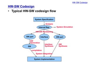
  • 3. HW-SW Codesign HW-SW Codesign • Typical HW-SW codesign flow System Implementation SW HW part Interface SW part Internal Rep. System Specification Analysis HW-SW Partitioning SW Generation Interface Synthesis HW Synthesis System Simulation compilation System Integration
  • 4. HW-SW Codesign • Polis – F. Balarin, et al., Hardware-Software Co-Design of Embedded Systems: The Polis Approach, Kluwer Academic Publishers, 1997. – A design environment for control-dominated embedded systems – MoC: CFSM (Co-design Finite State Machine) • Globally asynchronous/locally synchronous – Formal verification or simulation for the analysis of a system at the behavioral level – It can generate C-code and HDL code – Weak points • Only CFSM: control-dominated application • Does not support estimation technique for complex processor models • Does not support multiple hardware and software partitioning
  • 5. HW-SW Codesign – Overall flow formal languges (Esterel) translators CFSMs partitioning partitioned CFSMs HW synthesis SW synthesis interface synthesis BLIF optimized hardware C code OS synthesis HW interface logic synthesis integration S-graph scheduler template + timing constraints simulation formal verification verification intermediate format translator
  • 6. HW-SW Partitioning HW-SW Partitioning • Partitioning system functionality into – Application specific hardware and – Software executing on one (or more) processor(s) • Partitioning problem – Find minimum cost HW-SW combination satisfying constraints • Cost = f (HW area, HW delay, SW size, SW time, interface size, interface delay, power, ... ) – Need efficient and accurate performance, cost, power estimation models – Need efficient partitioning algorithms • Greedy method • Simulated annealing • Kernighan-Lin • Integer linear programming • Global criticality/local phase • Manual • ...
  • 7. HW-SW Partitioning • ILP-based approach – R. Niemann and P. Marwedel, “Hardware/software partitioning using integer programming,” Proc. ED&TC, Mar. 1996. – Concurrent partitioning, scheduling, and sharing – Integer linear programming – Minimize design cost with performance & resource constraints VHDL C code VHDL code retargetable compilation high-level synthesis SW costs HW costs partitioning (solve ILP) cluster SW nodes retargetable compilation SW costs
  • 8. HW-SW Partitioning • Global criticality/local phase – A. Kalavade and E. A. Lee, “A global criticality/local phase driven algorithm for the constrained hardware/software partitioning problem," Proc. Codes/CASHE, Sept. 1994, pp. 42-48. – Global Criticality/Local Phase (GCLP) • GC – Global time-criticality (feasibility) – Node-invariant • LP – Classify each node into three phases: extremity, repeller, normal – Determine mapping and start time for each node – Quadratic complexity – Task/process level of granularity
  • 9. HW-SW Partitioning – Objective function • Not hardwired • Selected at each step according to GC & LP
  • 10. HW-SW Partitioning – Global criticality • Probability that an unscheduled node (in U) should be implemented in HW to meet latency constraint • Algorithm 1. Estimate H nodes to move to HW according to priority (more performance, less area --> gets higher priority) so that the remaining SW nodes can be executed within Tremaining 2. Compute actual finish time 3. If not feasible, go to 1. 4. Compute GC=(size of H)/(size of U), size: number of elementary operations
  • 11. HW-SW Partitioning – Local phase 1: extremity • Determine extremity sets EXs and EXh – Local phase 2: repellers • Software repeller property – Bit-level instruction mix, precision level • Hardware repeller property – Memory-intensive instruction mix, table-lookup instruction mix
  • 12. HW-SW Partitioning – Compute D • If i  (EXs  EXh), -0.5<D<0.5 depending on the level of extremity (more negative if HW is preferred) • Else if repeller, -0.5<D<0.5 depending on the repeller value (more negative if HW is preferred) • For a normal node, D=0
  • 13. HW-SW Partitioning – Experimental results • ILP: several hours • GCLP: order of seconds • Good solution: low HW area and high DSP utilization – HA: hardware area, SA: software area, Util: DSP utilization
  • 14. HW-SW Partitioning • Implementation-bin selection – A. Kalavade and E. A. Lee, "The extended partitioning problem: hardware/software mapping and implementation-bin selection," Proc. of the 6th International Workshop on Rapid. Systems Prototyping, 1995. – Mapping and implementation-bin selection (MIBS)
  • 15. HW-SW Partitioning – Algorithm • Perform GCLP-based HW-SW partitioning – Use median values for the HW cost/time – Implementation-bin selection is applied to HW only but it is also applicable to SW • Bin Fraction Curve (BFC) – Fraction of free nodes that need to be mapped to their L bins • Bin Sensitivity Curve (BSC) – Slopes of the BFC
  • 17. HW-SW Partitioning – Algorithm • Weighted bin sensitivity curve
  • 18. HW-SW Partitioning – Results mapped to L bins mapped to median implementation bins
  • 19. Platform-Based Design Platform-Based Design • Trend in System-on-Chip (SoC) design – Larger design space • Exponentially growing transistor counts (Moore's law) • Ever increasing complexity of applications • Multi-functional and multi-standard – More flexibility, higher performance, lower energy, ... – Shorter Time-to-Market – Need more efficient design methodology 0.001 0.01 0.1 1 10 100 1000 10000 M Logic Transistors/Chip 0.01 0.1 1 10 100 1000 10000 100000 1981 1983 1985 1987 1989 1991 1993 1995 1997 1999 2001 2003 2005 2007 2009 K Transistors/Staff-Month Complexity Productivity Complexity 58%/yr growth rate Productivity 21%/yr growth rate Complexity Productivity
  • 20. • Reuse of – Cell (standard cell) – IP – Architecture (platform) --> platform-based design – IC (reconfigurability) Memory Video RAM I/O Host interface DSP core 1 (D950) Modem DSP core 2 (D950) Sound ASIP 1 Master Control ASIP 2 Memory Controller ASIP 3 Bit Manipulation ASIP 4 (VLIW DSP) Programmable video operations, standard extensions I/O S interface Glue logic A/D & D/A High-speed HW Video operations for DCT, IDCT, motion estimation Single chip videophone (H.263) Platform-Based Design
  • 21. Platform-Based Design • Platform and derivative design Hard IP Soft IP Others EDA Integrator Application specific integration platform EDA Tools EDA Tools Derivative
  • 22. Platform Design-Space Exploration Platform Specification Architectural Space Application Space Application Instance Platform Instance System Platform Large Design-Space Exploration Application Space Application Instance Architectural Space Platform Instance Conventional Design Platform-Based Design Platform-Based Design • Design-space exploration
  • 23. Platform-Based Design • Taxonomy of SoC platforms – Full-Application Platforms • Philips Nexperia • TI OMAP (Open Multimedia Application Platform) • ARM PrimeXsys • Intel Xscale Architecture – Processor-centric platform • Improv Jazz • Tensilica Xtensa – Communication-Centric platform • ARM AMBA bus architecture • Sonics mNetwork • IBM CoreConnect – Fully Programmable Platform • Altera Excalibur • Xilinx Virtex-II Pro
  • 24. Platform-Based Design • Full-application platform – Concentrates on full application • Delivers comprehensive set of libraries hardware and software • Delivers several mapping and application examples – Texas Instruments OMAP Application domain: 2.5G/3G Wireless mobile devices – Philips Nexperia Application domain: Digital Video, Digital Audio, Mobile Communications
  • 25. Platform-Based Design • Texas instrument OMAP1610 – Dual processor core • ARM926, TI DSP • Up to 200MHz – Multimedia cores • 2D Graphics accelerator • LCD controller • MMC interface • USB interface – Wireless supports • Bluetooth • 3G
  • 26. Platform-Based Design • Nexperia platform Scalable VLIW Media Processor: • 100 to300+ MHz • 32-bit or64-bit Nexperia™ System Buses • 32-128 bit General-purpose Scalable RISC Processor • 50 to300+ MHz • 32-bit or64-bit LibraryofDevice IP Blocks • Image coprocessors • DSPs • UART • 1394 • USB …and more TM-xxxx D$ I$ TriMedia CPU DEVICE IP BLOCK DEVICE IP BLOCK DEVICE IP BLOCK . . . DVP SYSTEMSILICON PI BUS SDRAM MMI DVP MEMORY BUS DEVICE IP BLOCK PRxxxx D$ I$ MIPS CPU DEVICE IP BLOCK . . . DEVICE IP BLOCK PI BUS TriMedia™ MIPS™
  • 27. Platform-Based Design • Nexperia software architecture – Scalable from low-end to high-end – Consistent API (on MIPS or TriMedia) – Single Streaming Architecture for MIPS and TriMedia – Aligned to Nexperia™ DVP (Digital Video Platform) HW architecture and IP blocks – Operating system independent software layers • OS abstraction libray • Supports Linux, pSOS, Windows CE – Re-use of software components on any instance of the platform
  • 28. Platform-Based Design • Processor-centric platform – Application Specific Instruction Set processor • Configure processor pipeline • Generate complete software development environment – Tensilica Xtensa Option: manually refine configuration Original C/C++ Code Evaluates millions of possible extensions: • SIMD operations • operator fusion • parallel execution Designer selects “best” configuration Run XPRES Compiler int main() { int i; short c[100]; for (i=0;i<N/2;i++) { Xtensa Processor Generator Tuned Software Tools Processor Hardware ALU DSP OCD Timer FPU Register File Cache
  • 29. Platform-Based Design • Configuration of Xtensa External Interface Base ISA Feature Configurable Function Optional Function User Defined Features (TIE) Optional & Configurable User Defined Queues and Wires JTAG Extended Instruction Align, Decode, Dispatch Xtensa Processor Interface Control Write Buffer Xtensa Local Memory Interface TRACE Port JTAG Tap Control On Chip Debug User Defined Execution Units and Interfaces Instruction Decode/Dispatch Base ALU Floating Point Vectra DSP MAC 16 DSP MUL 16/32 User Defined Register Files Instruction Fetch / PC Data Load/Store Unit Data ROMs Data RAMs Data Cache Data MMU User Defined Execution Units User Defined Register Files Vectra DSP Base Register File User Defined Execution Unit Vectra DSP Processor Controls Interrupt Control Data Address Watch Registers Instruction Address Watch Registers Timers Used Defined Data Load/Store Units Instruction ROM Instruction RAM Instruction Cache Instruction MMU PIF Exception Support Exception Handling Registers Trace Interrupts
  • 30. Platform-Based Design • Communication-centric platform – Concentrates on communication back-bone (or On-chip Interconnection) - Delivers communication framework (plus generic peripherals) – Sonics SiliconBackplane , PALMCHIP CoreFrame
  • 31. Platform-Based Design • Fully programmable platform – Concentrates on reconfigurability • Delivers processor plus programmable logic – Xilinx Virtex-II Pro (Platform FPGA) – Altera Excalibur (Platform FPGA)
  • 32. Platform-Based Design • Xilinx Virtex-II Pro – PowerPC uP (400MHz) – FPGA logics – Internal RAM – Serial transceiver – XtremeDSP functions – Digitally controlled impedance
  • 33. Platform-Based Design • Altera Excalibur ARM922T Cache MMU AHB1 Interrupt Controller Watchdog Timer SDRAM Controller Single Port SRAM0 Single Port SRAM1 Dual Port SRAM0 Dual Port SRAM1 AHB2 AHB1- AHB2 Bridge EBI UART Timer (Configuration) Register Flash Rom SRAM Master Slave Slave Master Stripe-to-PLD Bridge PLD-to-Stripe Bridge PLD 1/2 PLL1 1/4 PLL1 Configuration Logic Master
  • 34. Platform-Based Design • System design flow Mapping Application HW synthesis HW Constraints Architecture SW synthesis SW Mapping results IF synthesis Estimation of performance, area, and power in HW and SW
  • 35. Application-to-Architecture Mapping Application-to-Architecture Mapping for(i = 0; i < 18; i++) { s = (mpfloat)0.0f; k = 0; do { s += X[k] * v[k]; s += X[k+1] * v[k+1]; s += X[k+2] * v[k+2]; s += X[k+3] * v[k+3]; s += X[k+4] * v[k+4]; s += X[k+5] * v[k+5]; k += 6; } while(k < 18); v += 18; ISCALE(s); t[i] = s; } /* correct the transform into the 18x36 IMDCT we need */ /* 36 muls */ for(i = 0; i < 9; i++) { x[i] = t[i+9] * Granule_imdct_win[gr->block_type][i]; ISCALE(x[i]); x[i+9] = t[17-i] * Granule_imdct_win[gr->block_type][i+9]; ISCALE(x[i+9]); x[i+18] = t[8-i] * Granule_imdct_win[gr->block_type][i+18]; ISCALE(x[i+18]); x[i+27] = t[i] * Granule_imdct_win[gr->block_type][i+27]; ISCALE(x[i+27]); } Application in C Platform architecture
  • 36. Application-to-Architecture Mapping • Y-chart approach – B. Kienhuis, E. Deprettere, K. Vissers, P. van der Wolf, "An approach for quantitative analysis of application- specific dataflow architectures," Proc. ASAP'97, 1997. Mapping Application Architecture Performance numbers Performance analysis
  • 37. Application-to-Architecture Mapping – Abstraction pyramid • A. Kienhuis, Design Space Exploration of Stream-based Datatow Architectures, Ph.D. Thesis, Delft University of Technology, 1999.
  • 38. Application-to-Architecture Mapping – Design trajectory Design approach using Y-chart environment Golden point design (low-level ad hoc design)
  • 39. Application-to-Architecture Mapping – Stack of Y-chart • Use different models at different levels of abstraction
  • 40. Application-to-Architecture Mapping – Mapping • A crucial step in DSE to evaluate the performance of different application-architecture combinations • For smooth mapping – Need a good match in data and operation types between the corresponding model of architecture and model of computation Architecture Application Model of architecture Model of computation Mapping match in data/operation type
  • 41. Application-to-Architecture Mapping – Model of computation (MoC) • A formal representation of the operational semantics of networks of functional blocks describing computations • Well-known MoCs – Discrete Events (DE) – Finite State Machines (FSM) – Process Networks (PN) – Synchronous Data Flow (SDF) – Synchronous/Reactive (SR) • Many different MoCs for various application domains • May need multiple MoCs for modeling an application
  • 42. Application-to-Architecture Mapping – Model of architecture (MoA) • A formal representation of the operational semantics of networks of functional blocks describing architectures • It is for modeling an architecture instance of the architecture template • Architecture template – A specification of a class of architectures in a parameterized form – Parameters are number of functional units, buffer size, bus type, latency, etc. • Architecture instance – The result of assigning values to parameters of the architecture template
  • 43. Application-to-Architecture Mapping • YAPI – E. de Kock, G. Essink, P. van der Wolf, J.-Y. Brunel, W. Kruijtzer, P. Lieverse, and K. Vissers, "YAPI: Application Modeling for Signal Processing Systems," Proc. DAC, 2000. – YAPI: Y-chart API – Application modeling for signal processing systems • For the reuse of signal processing applications • For the mapping of signal processing applications onto heterogeneous systems – Kahn process network (KPN) • Often used for modeling signal processing applications • Concurrent processes communicate through unidirectional first-in-first-out channels – Blocking read – Non-blocking write • Deterministic
  • 44. – A limitation of KPN • Cannot model reactiveness such as user interaction, that is, non-deterministic events • Control flow models such as finite state machines are a solution, but less suited for the implementation of computationally intensive applications. – To extend KPN with non-deterministic events • Introduce a communication primitive (channel selection primitive) – YAPI separates the concerns of the application programmer and the system designer. – Implementation of YAPI • In the form of a C++ run-time library – Read(), write(), execute(), and select() – The implementation of these functions is a concern of the system designer (may be implemented in different ways). Application-to-Architecture Mapping
  • 45. Application-to-Architecture Mapping – Architecture evaluation in YAPI • VIDEOTOP application – The top-level process network model Channel selection to be decoded MPEG2 stream ts: transport stream pid: packet id pes: packetized elementary stream es: elementary stream
  • 46. Application-to-Architecture Mapping • Simulation to measure the workload – Communication requirement • The amount of data that is transferred between processes – Computation requirement • The amount of computation of processes • From the result – We know that the required communication bandwidth is 150MB/s – We select initial architecture as input for a more detailed mapping and performance analysis
  • 47. Application-to-Architecture Mapping • Trace-driven approach – P. Lieverse, P. van der Wolf, E. Deprettere, K. Vissers, "A methodology for architecture exploration of heterogeneous signal processing systems," Proc. SIPS, 1999. – SPADE (System level Performance Analysis and Design space Exploration) – For architecture exploration of heterogeneous signal processing systems – Support an explicit mapping step – Cosimulation of application models and architecture models using trace-driven simulation technique • Architecture model do not need to model the functional behavior, still handling data dependent behavior correctly
  • 48. Application-to-Architecture Mapping – In SPADE, applications and architectures are modeled separately. • An application imposes a workload on the resources provided by an architecture • Workload – Computation and communication workload • Resources – Processing resources • Programmable cores or dedicated hardware – Communication resources • Bus structures and memory resources such as RAMs or FIFO buffers
  • 49. Application-to-Architecture Mapping – Trace-driven simulation • Application model – A network of concurrent communicating processes • Each process of application model – Produce a so-called trace which contains information on the communication and computation operations • The traces get interfaced to an architecture model – Drive computation and communication activities in the architecture
  • 50. Application-to-Architecture Mapping – Application modeling • Kahn Process Network model • Modeled with YAPI based API – read(), write(), and execute() – They generate trace entries – execute() function takes a symbolic instruction as an argument – Architecture modeling • Architecture model does not model the functional behavior • It is constructed from generic building blocks – Trace driven execution unit (TDEU) • Interprets trace entries and has a configurable number of I/O ports – Interfaces • Translates the generic protocol (FIFO) into a communication resource specific protocol (e.g. bus) void Tidct(void) { ... while(1) { In->read(mb_in); mb_out = Idct(mb_in); execute(IDCT_MB); Out->write(mb_out); } }
  • 51. Application-to-Architecture Mapping – Architecture modeling (Cont’d) • All blocks are parameterized – TDEU: a list of symbolic instructions and latencies – Interface block: buffer size, bus width, setup delay and transfer delay
  • 52. Application-to-Architecture Mapping – Mapping • Each process is mapped onto a TDEU – Can be many-to-one • Need to be scheduled by the TDEU (round robin) • Each process port is mapped one-to-one onto an I/O port – Simulation • Concurrent simulation of the application model and the architecture model • Architecture simulation – TSS (Tool for System Simulation): Philips in-house architecture modeling and simulation framework
  • 53. Application-to-Architecture Mapping • Heterogeneous multiprocessor scheduling – H. Oh and S. Ha, "A hardware-software cosynthesis technique based on heterogeneous multiprocessor scheduling," Proc. CODES, May 1999. – Perform list scheduling with the allocated PEs heterogeneous multiprocessor scheduler task-PE allocation controller performance evaluation cosynthesis result Fail task-PE time table Good
  • 54. Application-to-Architecture Mapping – Task-PE allocation controller • Allocate additional PEs until the given time constraint is satisfied • Lock: initially lock all PE's except the lowest cost ones • Unlock: select PE giving largest perf_gain/cost_increase • Re-lock: in reverse order if time constraint is met A B C D C A B D P0 P1 P0(HW) P1(1) P2(5) B0 B1 B2 A 3(4) 2(6) 1(10) 7 2 B 4(5) 2(8) 1(10) 10 3 C 2(3) 1(5) 5 2 D 5(10) 3(15) 15 5 task-PE profile table exec time(cost) processor cost P0 P1(1) P2(5) B0 7 10 2(3) 15 solution
  • 55. Application-to-Architecture Mapping – Scheduler • List scheduling is used • Priority for the list scheduling is given by BIM – E(i,j): execution time of node i on processor j – C(i,d): IPC overhead between i and d (child node of i) – T(i,j): PE j is available after T(i,j) – BIL(i,j)=E(i,j)+maxd[min(BIL(d,j), mink(BIL(d,k)+C(i,d)))] – BIL(i,j) is the critical path length from node i to the sink. – BIM(i,j)=T(i,j)+BIL(i,j) i d1 processor j C(i,d1) E(i,j) e i T(i,j) E(i,j) d1 processor k1 d1 sink d2 C(i,d2) processor k2 d1 sink e d2 BIL(i,j) BIL(dx,?)
  • 57. Application-to-Architecture Mapping • Pipelined heterogeneous multiprocessor system – Seng Lin Shee and Sri Parameswaran, "Design methodology for pipelined heterogeneous multiprocessor system," Proc. DAC, June 2007. – Pipelining with ASIPs as processing entities
  • 58. Application-to-Architecture Mapping – Tensilica Xtensa LX processors are used for the ASIPs • Queue interface • Xtensa PRocessor Extension Synthesis (XPRES)
  • 60. Application-to-Architecture Mapping – Exhaustive search for optimal configuration • Complexity = O(np) where n: number of possible processor configurations p: number of processors
  • 61. Application-to-Architecture Mapping – Heuristic • Find critical node (processor with worst minimum core iteration runtime) • Find minimum cost configuration for the critical node • For every other node vj, – Filter out configurations that are faster than the critical node – Find minimum cost configuration for vj v1 v2 v3 v4 r1 c1 r2 c2 r3 c3 r4 c4