


Casing (2) casing setting depth casing string
- 1. Casing Design Theory and Practice Dr. Ibrahim Salahudin Mohamed Upstream Oil and Gas Business Consultant
- 2. Casing Design Philosophy In practice, it would be much cheaper to drill a single size hole to total depth (TD), probably with a small diameter drill bit, and then to case the hole from the surface to the TD. Do you agree on that?
- 4. Two wells have the same total depth, but with two different casing setting depths and profiles Why?
- 5. FUNDAMENTAL ASPECTS OF CASING At a certain stage during the drilling of oil and gas wells, it becomes necessary to line the walls of a borehole with steel pipe which is called casing.
- 7. Typical Casing Strings ØConductor Casing ØSurface Casing ØIntermediate casing (Protective) ØProduction Casing ØLiner
- 8. Drive or Conductor Ø Conductor pipe is run from the surface to some shallow depth, typically, 20 to 300 feet deep ) Ø May be drilled, hammered, or jetted.
- 10. Drive Shoe
- 12. Drive or Conductor Ø Conductor pipe is used to: ü Hold back the unconsolidated surface formations and prevent them from falling into the hole ü To protect near-surface unconsolidated formations from washout. ü Supports weight of other casing strings. ü Provide a circuit for the drilling mud to elevated mud tanks ü Provides protection against shallow gas flows by installing the diverter system.
- 15. Surface Casing ØThe surface casing is run after the conductor casing ØThe surface casing is used to : ü Protect fresh water from contamination from drilling fluids ü The surface casing also serves to provide protection against shallow blowouts as drilling progresses, hence BOPs are connected to the top of this string ü Support the weight of subsequent casing strings ü Prevent caving of weak formations that are encountered at shallow depths
- 18. Surface Casing ØThis casing should be set in competent rocks such as hard limestone. ØThis will ensure that the formations at the casing shoe will not fracture at high hydrostatic pressures which may be used later.
- 19. Intermediate Casing (Protective Casing) ØThe main reason for setting intermediate casing is to case off the formations that prevent the well from being drilled to the total depth. Ø Troublesome zones encountered include those with: ü Abnormal formation pressures, ü lost circulation, ü Unstable and sloughing shales and ü Salt sections.
- 20. Production Casing ØProduction string represents the last casing string. Ø It is run to: ü Isolate producing zones. ü Permit selective production in multizone production ü Acts as the conduit or a host for production fluid tubing (The production tubing fits inside the production string) ü To provide reservoir fluid control and protecting the environment in the event of failure of the tubing string during production operations
- 22. Production Casing ØSize is highly dependent on ü Production tubing size ü Completion equipment ü Artificial lift constraints
- 24. Liner Ø Liners are the pipes that do not usually reach the surface but are suspended from the bottom of the next largest casing string. Ø Usually, they are set to : Ø Seal off troublesome sections of the well Ø Through the producing zones for economic reasons. In liner completions, both the liner and the intermediate casing act as the production string.
- 26. Types of liner ØDrilling liners : Used to isolate lost circulation or abnormally pressured zones to permit deeper drilling. ØProduction liners: Run instead of a full casing to provide isolation across the producing or injection zones.
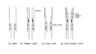
- 27. Types of liner ØThe scab liner üA section of casing that does not reach the surface. It is used to repair existing damaged casing. üIt is normally sealed with packers at top and bottom and in some cases is also cemented ØThe tie-back liner: A section of casing extending upwards from the top of an existing liner to the surface or well head. ØThe scab tie-back liner A section of casing extending from the top of an existing liner but does not reach the surface.
- 30. Drilling Liner
- 31. Bad Cement Job
- 35. Liner casing ØNeeds an overlap with previous string of 300 to 500 feet Ø Liners are hung on the previous casing, by use of a suitable arrangement of a packer and slips called a liner hanger.
- 39. Principles of Casing Design Casing Setting Depth Casing Size Casing Grade
- 40. Casing Setting Depth When we make a determination of the setting depths for the various casing strings in our well, there are several parameters that we must consider: ü Experience in an area ü Pore pressure (formation fluid pressure) ü Fracture pressure ü Borehole stability problems ü Corrosive zones ü Environmental considerations and Government Regulations ü Company policy
- 41. The experience parameter Ø Successful experience in an area with previous wells is the most reliable of all Ø It should never be skipped out of hand in order to try something else thought to be more “technologically advanced” or more “cost effective.” Ø The most important question is “ Why such profile is successful?” Ø Too often, blind use of such experience without understanding, can result in something going wrong when least expected. Ø In brief, you should understand why such profile is successful.
- 42. Pressure Terms Definition ØSome important terms should be understood first: ØPore Pressure or Formation Pressure ØFracture Pressure ØOverburden Pressure ØNormal Pressure ØAbnormal Pressure ØSubnormal Pressure
- 43. Pore Pressure- Formation Pressure ØThe magnitude of the pressure in the pores of a formation. Ø If the pore throats through the sediment are interconnecting all the way to surface, the pressure of the fluid at any depth in the sediment will be same. ØThe pressure in the fluid in the pores of the sediment will only be dependent on the density of the fluid in the pore space and the depth of the pressure measurement ØIt will be independent of the pore size or pore throat geometry
- 45. Pressure Calculations � ��� = 0.433 ∗ � � �� ∗ ����ℎ �� � ��� = 0.052 ∗ � ��� ∗ ����ℎ �� � ��� = 1 144 ∗ � ��� ∗ ����ℎ ��
- 46. Normal (Hydrostatic) Pore Pressure Gradient Ø Most of the fluids found in the pore space of sedimentary formations contain a proportion of salt and are known as brines. Ø The dissolved salt content may vary from 0 to over 200,000 ppm. Ø Correspondingly, the pore pressure gradient ranges from 0.433 psi/ft (pure water) to about 0.50 psi/ft. Ø In most geographical areas, the pore pressure gradient is approximately 0.465 psi/ft (assumes 80,000 ppm salt content).
- 47. Overburden Pressure- Geostatic Pressure Ø The vertical pressure at any point in the earth is known as the overburden pressure or geostatic pressure. Ø The overburden pressure at any point is a function of the mass of rock and fluid above the point of interest. Ø In order to calculate the overburden pressure at any point, the average density of the material (rock and fluids) above the point of interest must be determined.
- 50. Overburden Pressure- Geostatic Pressure Ø Since the matrix material (rock type), porosity, and fluid content vary with depth, the bulk density will also vary with depth. Ø The overburden pressure at any point is therefore the integral of the bulk density from surface down to the point of interest. Ø On average, it is assumed that the maximum bulk density encountered is around 2.3 g/cc. this would result in overburden gradient of 1 psi/ft
- 51. Abnormal Pressure Vs. Subnormal Pressure If the pore pressure is higher than the normal pressure (0.465 psi/ft) Abnormal Pressure or Over-Pressured If the pore pressure is less than the normal pressure (0.465 psi/ft) Sub normal or under- Pressured Zone
- 54. Abnormal Pressure Mechanism ØIf the overburden is increased (e.g. due to more sediments being laid down) the extra load must be borne by the matrix and the pore fluid. ØIf the fluid is prevented from leaving the pore space the fluid pressure must increase above the hydrostatic value. ØSuch a formation can be described as over-pressured i.e. part of the overburden stress is being supported by the fluid in the pore space and not the matrix. ØSince the water is effectively incompressible the overburden is almost totally supported by the pore fluid and the grain-to-grain contact stress is not increased.
- 55. Force
- 57. In a formation where the fluids are free to move (drainage path open), the increased load must be taken by the matrix, while the fluid pressure remains constant. Under such circumstances the pore pressure can be described as Normal, and is proportional to depth and fluid density
- 58. Abnormal Pressure Conditions ØIn order for abnormal pressures to exist the pressure in the pores of a rock must be sealed in place i.e. the pores are not interconnecting. ØThe seal prevents equalization of the pressures which occur within the geological sequence. ØThe seal is formed by a permeability barrier resulting from physical or chemical action. ØA physical seal may be formed by gravity faulting during deposition or the deposition of a fine-grained material (shale) ØThe chemical seal may be due to calcium carbonate being deposited, thus restricting permeability.
- 59. TRANSITION ZONE Ø It can be seen that the pore pressures in the shallower formations are “normal”. That is that they correspond to a hydrostatic fluid gradient. Ø There is then an increase in pressure with depth until the “over-pressured” formation is entered. Ø The zone between the normally pressured zone and the over-pressured zone is known as the transition zone Ø The pressures in both the transition and over-pressured zone is quite clearly above the hydrostatic pressure gradient line. Ø The transition zone is therefore the seal or caprock on the over-pressured formation
- 61. Formation Fracture Pressure ØFormation fracture pressure is the pressure at which the formation will frac. ØThe well operations can then be designed such that the pressures in the borehole will always lie between the formation pore pressure and the fracture pressure. ØIf the pressure in the borehole falls below the pore pressure then an influx of formation fluids into the wellbore may occur. ØIf the pressure in the borehole exceeds the fracture pressure then the formations will fracture and losses of drilling fluid will occur
- 63. Fracture Mechanism ØThe stress within a rock can be resolved into three principal stresses ØA formation will fracture when the pressure in the borehole exceeds the least of the stresses within the rock structure. ØNormally, these fractures will propagate in a direction perpendicular to the least principal stress
- 64. The Leak-Off Test- Formation Integrity test FIT ØIn practice, formation fracture pressures or, as they are commonly called, formation breakdown pressures are determined in leak-off tests. ØThese tests are normally performed at the start of each new hole section, just after drilling out of a casing shoe of the previous hole section.
- 65. Leak off Test ØThe procedure is as follows: 1. Drill to 5 - 10 ft below the casing shoe 2. Close the BOPs at surface 3. Raise the surface pressure in increments and record the volume pumped and the pressure in the system at each volume increment (4. 4. Stop pumping when the pressure in the well does not increase linearly for an increase in the volume of fluid pumped into the well The operation is generally stopped at the first point which deviates from the straight line portion of the plot
- 68. Maximum Mud Weight ØGiven the leak-off test pressure just below the casing shoe, the maximum mud weight that can be used at that depth, and below can be calculated from ØUsually, a safety factor of o.5 ppg (0.026 psi/ft) is subtracted from the allowable mud-weight.
- 69. Quiz While performing a leak off test the surface pressure bled off at 940 psi. The casing shoe was at a true vertical depth of 5010 ft and a mud weight of 10.2 ppg was used to conduct the test. What is the maximum mud weight that can be used during drilling the subsequent section
- 71. Calculating the Fracture Pressure of a Formation Ø The leak-off test pressure described above can only be determined after the formations to be considered have been penetrated. Ø It is however necessary, in order to ensure a safe operation and to optimize the design of the well, to have an estimate of the fracture pressure of the formations to be drilled before the drilling operation has been commenced. Ø In practice the fracture pressure of the formations are estimated from leak-off tests on nearby (offset) wells.
- 72. Estimating of Fracture Pressure ØWhen planning exploration or wildcat wells, where there is little or no reliable offset well data, the fracture gradient can be estimated using various predictive techniques. Ø It is usually assumed that the fracture gradient at the casing shoe is the lowest within the open hole section. ØFracture gradient estimates made whilst drilling are normally the responsibility of the mud logging contractor.
- 73. Hubbert and Willis method ØAccording to the Hubbert and Willis method, the total injection (or fracturing) pressure, FP, required to keep open and extend a fracture is given by:
- 75. Eaton method ØThe Eaton method is the most widely used in the oil industry. For sedimentary rocks, the Passion's ratio is assumed to be 0.4 unless it is measured
- 76. Example
- 77. Casing Setting Depth - Conductor ØConductor casing may require the drilling of a hole in the ground and cementing in place or it may be driven into the ground with a diesel pile- driving hammer. ØOn the simple side, we want the conductor deep enough to prevent washing out under the rig or platform while drilling the surface hole
- 78. Casing Setting Depth - Conductor Ø For many shallow wells with hard surface soils the conductor may be set at depths of 50 ft or so, sometimes 100 ft. Ø On the other hand, in areas where the surface soils (or ocean bottom) are extremely soft it may be necessary to set the conductor 200-500 ft below the surface (or ocean bottom) just to drill the hole for the surface casing Ø The setting depth of conductor in many cases must be determined by soil bearing tests and coring.
- 79. Setting Depths Using Pore and Fracture Pressure
- 80. Pressure Plots In drilling engineering, it is convenient to report the pressures i.e ( mud pressure, formation and fracture pressure) in terms of gradient or more practically in density units.
- 81. Differential Pressure- Overbalance ØIf the mud pressure in the well is higher than the pore pressure, the differential pressure is called overbalance ØIf the mud pressure is less than the pore pressure then the differential is known as the underbalance pressure.
- 83. Safety Margins (Trip Margin) ØThe mud density must be slightly higher than the formation pressure to prevent formation fluids from entering the borehole ØEspecially when making trips because the action of pulling the pipe tends to cause a negative pressure (Swap effect) or a reduction in the hydrostatic pressure while the pipe is in motion. ØThis margin is referred as a trip margin.
- 84. Safety Margins (Kick Margin) ØAt the same time the density must be less than the fracture pressure so that the drilling fluid does not fracture and enter the formations, ØEspecially, during running the drill string into the hole causes positive pressures (surge effect). ØThis margin is called as frac margin or kick margin.
- 85. Trip margin Kick margin A mount of the margin depends on the company policy, but in general may be up to 200 psi, 0.06 specific gravity, or 0.5 ppg
- 86. 1700 ft
- 88. According to me, it may not be safe to drill approximately 10000 ft with out any protection, even if all the conditions are okay Optional for safety
- 89. According to me, it may not be safe to drill approximately 10000 ft with out any protection, even if all the conditions are okay Optional for safety
- 93. Assume that the overburden gradient is 1 psi/ft and the passion ratio is 0.4 calculate the casing setting depth
- 94. I. From the given pore pressure, we calculate the mud weight by adding 200 psi overbalance. II. Then calculate the pore pressure gradient and the mud gradient by dividing the proposed pressures by the depth. III. Calculate the fracture pressure gradient using the overburden gradient and the passion’s ratio. IV. Then subtract .06 or 0.5 ppg as a kick margin Solution
- 99. Casing Size Selection ØAfter determining the number of casing strings required and the setting depths the next step in the design procedure is to select the sizes of casing required. Ø What size casing and what size bits do we require? ØThe two important things to know about selection of casing size are as follows: ü Hole size determines casing size ü Hole size at any point in the well except the surface is determined by the previous string of casing
- 100. Casing Size Selection ØIn selecting casing size, we usually start with the casing size at the bottom of the hole and work to the top. ØThe size of the last string of casing run in a well is generally determined by the type of completion that will be employed. ØThat decision is usually the function of an interdisciplinary team of reservoir, production, and drilling personnel
- 101. Casing Size Selection Workflow ØOnce we know the diameter of the final string of casing or liner, the process proceeds like this: ü Determine the hole size (bit size) for the final string of casing. ü Determine what diameter casing will allow that size bit to pass through it. That is the size of the next string of casing. ü Repeat the procedure until all of the hole sizes and casing sizes have been determined.
- 102. Borehole size selection- Role of Thumb ØThere are no formulas for determining the ideal borehole size. ü A borehole must be large enough for the casing to pass freely with little chance of getting stuck. ü There should be enough clearance around the casing to allow for a good cement job. ü In general, the bigger the borehole the more costly it is to drill ü Do not forget to check your inventory for the available casing sizes.
- 103. Borehole size selection- Role of Thumb ØSelecting the borehole size is primarily based on current practices in the area or areas with similar lithology. ØThere are a number of charts and tables in the literature, some good for some areas, but greatly lacking for other areas. ØThe best advice we can offer is to use what is common practice in the area unless there is good reason to do otherwise. Ø No matter what specific charts we suggest here, they going to be wrong for some particular locale or application.
- 104. Hard Formations Soft Unconsolidated Formations
- 105. Exercise Example: ØAssume that we have determined the following casing depths: ØSurface casing: 3000 ft ØIntermediate casing: 10,500 ft ØProduction casing: 14,000 ft ØThe production engineers tell us they will require a production casing diameter of 7 in., Assume that the well is in an area of unconsolidated formations. ØDetermine the optimum casing sizes for this well.
- 107. 7 “ Production Casing 8.75 “ Bit (Production hole) 9 5/8” Intermediate Casing 12 ¼ “ Bit (Intermediate Hole) 13 3/8 Surface Casing 17 ½ “ Bit (Surface Hole) 20” Conductor Casing
- 108. ØFor the previous example, if the bore hole not stable and we have a serious well bore stability problem, the operator may elect to use large dimeters to account for. ØUnder such conditions, the experience in the area should be respected.
- 110. Casing Loads ØTo determine the strength of the casing needed, we must now consider the types and magnitudes of the loads the casing must safely bear. ØThree basic types of loads commonly are considered: ü Collapse loads ü Burst loads ü Axial loads
- 111. Casing Loads ØCollapse loads: are differential pressure loads in which the outside pressure exceeds the inside pressure, tending to cause the casing to collapse. ØBurst loads: are differential pressure loads in which the inside pressure exceeds the outside pressure, tending to cause the casing to rupture or burst ØAxial loads: are tension or compression loads mostly caused by gravitational and frictional forces on the pipe, but they can also be caused by pressure and temperature changes as well as bending in curved wellbores
- 112. Casing Loads ØThe collapse and the burst loads: ü Dictated by well conditions and anticipated operations in the well. ü They are functions of formation pore pressures, fracture pressures, drilling fluid pressures, and cement pressures. ØThe axial load: ü A function of the casing selection process itself; in other words, the ü Axial load is a function of the weight of the casing selected.
- 113. Design Philosophy for Load Calculations-1 Ø We almost always are able to determine loads if all is perfect, Ø we can almost always determine the type of loading that would take place if things go totally worse, but between those two situations is a great unknown. Ø Hence, our most logical approach is to assume the worst case that can happen, and that is the one we typically use for our casing design. Ø W do not concern ourselves with the probability of such loading occurring. Ø Always assume the worst situation will happen.
- 114. Design Philosophy for Load Calculations The thing that we have to always keep in mind is that we can not change our designed casing string once it is in the ground and cemented. If that “unlikely” worst case should occur, it is too late to change our design
- 115. Types of pressure loads under the worst case • Collapse Loading ü Minimum internal pressures ü Maximum external pressures • Burst Loading ü Maximum internal pressures ü Minimum external pressures
- 116. Sources of pressure loads Formation fluids Ø Water (fresh or salty) ØOil ØGas Drilling fluids ØWhole mud ØMud filtrate Un-set cement ØWhole cement ØCement filtrate ØStimulation fluids ØOcean or surface water ØAtmosphere Other Sources
- 117. The Design Philosophy -2 Ø It is relatively easy to ascertain the internal pressures for design purposes because we almost always know the internal fluids, at least in the design stages. Ø The difficulty is that we seldom know the external fluids and pressures once the casing is in the ground and cemented. Ø The most common approach is to consider the worst case, not the most likely case Ø All we can do is make some reasonable assumptions, and what is reasonable to one engineer may not be reasonable to another Ø Casing design is too subjective depending on your boundary conditions.
- 118. Gas Pressure Loads ØAssuming the encountered formation contains Methane (16 MW)
- 120. Collapse Load
- 121. Collapse Load
- 122. Collapse Load
- 123. Collapse Load Determination In the case of collapse loading, our task is to determine the minimum amount of pressure the casing will have inside and the maximum amount of pressure the casing will have on the outside (simultaneously at any given stage in the operations). Maximum External Pressure Minimum Internal Pressure
- 124. Collapse Loads- Internal Loads ØSources of internal loads: ü Evacuated casing (fully or partially) ü Gas ü Oil ü Freshwater ü Field saltwater ü stimulation fluids ü Drilling or workover fluids ü Combinations and partial columns of these
- 125. Collapse Loads ØSources of External Pressure: ü Freshwater ü Saltwater ü Formation pressure ü Drilling fluid ü Cement (un-set) Ø The internal and external loads depend on our assumptions for the worst case during our design process
- 126. Load Cases ØWe categorize the loading cases by the operational stages into: ü Running and installation ü Drilling stage of the next hole ü Production Phase. ØWe further breakdown the operations into different events and possible occurrences that may take place within those three operational stages.
- 127. Installation Stage- Collapse Load ØThe installation stage includes: ü Running the casing in the well and ü Cementing of the casing string. Ø During running the casing string, we have only one collapse scenario in which the casing is run empty or partially empty. Ø During the cementing phase, the collapse may occur because the cement density in the annulus is greater than the density of the fluids inside the casing string
- 128. Drilling Stage – Collapse Loads ØCollapse during drilling is almost always caused by loss of internal pressure from lost circulation. ØIn some cases, it can be severe enough to completely evacuate the casing
- 130. Drilling—lost circulation, evacuated ØComplete evacuation occurs when a very weak zone below the casing fractures and allows the drilling mud to enter ØThe hydrostatic head is reduced and the mud level in the well drops. ØContinued pumping only pumps more mud into the fractured zone and does nothing to keep the mud level above a static equilibrium with the fractured zone ØIn some severe cases, the casing string may be completely evacuated. ØComplete evacuation is usually happens when drilling below the surface casing .
- 131. Collapse Load- Lost of Circulation ØFor surface casing, we usually design for a fully evacuated string, but ØFor intermediate casing, we seldom see a fully evacuated string and to design for such, might seem a bit too conservative. ØIn intermediate casing design, we prefer to assume that the well will be full with fresh water ( never keep the well empty, pump something )
- 132. Production stage—collapse loads ØThis case applies primarily to the production casing. ØOne may not think of collapse as a possibility during the producing life of a well. ØBut to the contrary, it is a very real possibility, perhaps not in the early stages but definitely in the later life of the well
- 133. Production stage—collapse loads ØProduction casing can be collapsed during the production phase for some common reasons like: ØProduction Evacuation ØArtificial Lift ØStimulation and Squeezing
- 134. Production—evacuation ØHow can a production string be evacuated? More easily than many might suspect.
- 135. Production Evacuation- Examples Ø For example, a packer in a gas well develops a slow leak, and the packer fluid is “produced” along with the gas until it is exhausted. Or, Ø The perforations sand up below the packer and the flowing gas well bleeds to atmospheric pressure (casing collapse below the packer). Ø Or another, a well is stimulated and coiled tubing is run to jet the well with nitrogen. The jetting removes all the fluid but the perforations are plugged. The nitrogen flow is stopped and bled to zero. The casing collapses below the packer.
- 136. Production—Artificial lift Ø Artificial lift poses similar hazards as evacuation. Ø It is common to bleed off the gas pressure from casing prior to a workover in a gas-lift well. Ø Depending on the liquid level in the casing a collapse situation might arise. Ø A submersible pump could pump a well “dry” if the perforations should plug
- 137. Production—stimulation, squeeze ØWhen a well is stimulated or squeeze cemented through perforations, the formation must be fractured to initiate pump in. ØThe collapse problem arises from the fact that whenever we fracture a formation through perforations we have no idea where the fluid is going in the annulus. ØIf there is a channel such that the casing above the packer experiences the fracture pressure it is possible that the casing could collapse above the treatment packer or retainer.
- 139. Burst loading ØFor burst loading, we seek to find the maximum internal pressure and the minimum external pressure occurring simultaneously at any given stage of operations
- 140. Burst loading
- 141. Burst loading ØIn burst loading, the external pressure is the resisting load, and the external loading in a burst situation normally is taken to be the lowest possible pressure externally. ØAt the surface of the string, that pressure (external ) is taken to be zero or atmospheric pressure. Ø In a subsea casing string, it would be the seawater pressure at the wellhead
- 142. External loads, burst ØWe can assume any external pressure loads in the annulus between the casing string and the well. Such as : ü Atmospheric pressure (at surface of string) ü Seawater pressure (at surface of string) ü Freshwater ü Saltwater ü Formation pressure ü Drilling fluid
- 143. Internal loads, burst ØWe have different sources for the internal pressure that may cause casing to burst. Such as : ü Gas ü Oil ü Water ü Combinations of gas and liquids ü Cement (liquid) ü Pump pressure (plug bump, test pressure, stimulations)
- 144. Burst Loads- Important Note ØIt is never acceptable to assume that hardened cement will give us support in burst, even though it will. Ø The problem with cement is that we have to design our string before the well is cemented. ØIf our cement job is near perfect, then we have additional support in those sections covered by cement.
- 145. Burst Loads- Important Note ØIf there is even a small interval where the cement is poor, then we have no support at that interval, and there is nothing we can reasonably do to change that. ØHence, we can never safely assume that the hardened cement gives us any benefit when we are in the design stage
- 147. Burst load cases ØBurst loading can occur in all stages of well construction and production. ØCasing burst may happen during: ü Installing the casing ü Drilling the next casing section ü Production phase
- 148. Installation—plugged float or annular bridge ØDuring cementing, there is always the possibility that a float could plug or the annulus could bridge while displacing the cement. ØSuch an unanticipated event would likely be accompanied by a significant increase in pump pressure before the cementer could become aware and shut off the pump
- 151. Installation—plug bump ØWhen the top wiper plug (on top of the cement) contacts the top float, it stops the displacement circulation and an increase in pressure occurs. ØThis is an anticipated event and the cementer applies a predetermined additional pressure above the displacement pressure before stopping the pump. This is referred to as the plug-bump pressure
- 152. Installation—plug bump ØIts purpose is to assure that the plug is indeed seated on top of the float. Assuming the float valve is failed, and because the cement is almost always more dense than the displacement fluid, the maximum differential pressure occurs when all the cement is displaced. ØThe magnitude of this pressure is a matter of preference, company policy, and so forth, but it is generally on the order of 500-1500 psi depending on the casing and well conditions
- 153. Installation—pressure test ØCasing should be pressure tested once it is in place. ØMany operators legitimately claim that the plug-bump pressure is the best test. If the casing holds pressure then there is no reason for it to leak later. Ø That is valid, but unfortunately, many regulations require a pressure test be performed later before drilling out the floats and proceeding to drill deeper
- 154. Installation—pressure test Ø Pressure tests are done after the cement has been placed and supposedly cured. Ø Our only question is, what is the fluid in the annulus? Simply put, we do not know. Ø About the best we can come up with is that in the worst case, it is the same as the mud the casing was run in. Ø Assuming the displacement fluid in the casing is the same density as original mud, then this case will give a uniform differential pressure test to the entire casing string.
- 155. Drilling stage—burst loads ØThere are only two general cases of burst loads that occur in the drilling stage of well construction. They are: ü The maximum mud density used in the casing before the next casing string is set and ü The pressure from a kick Again, Do not assume any support from the cement behind the casing string
- 156. Drilling—maximum mud density Ø We always know, the maximum mud density we will use in drilling below a casing string to reach the next casing point. Ø What we never know is the fluid in the annulus. So again we take a worst case scenario that is within reason. Ø For surface casing we generally assume something like freshwater for surface casing and maybe saltwater for intermediate casing. Ø Some would assume the mud the casing was run in and others might assume formation pressure. Ø For simplicity (and lack of data), most use freshwater or saltwater in basic design
- 157. Drilling—well kick ØThere are three fluids involved in kicks: gas, oil, and saltwater. ØOf these, gas is the most severe and dangerous ØWe normally assume that the kick originates at the highest pressure zone below the casing string, and that in the worst case we have a solid column of the formation fluid (gas, oil, or saltwater) all the way to the surface. ØAll well-control methods are designed to prevent that, but it happens, and when it does, it is too late to change the casing design
- 158. Drilling—well kick ØThere are two approaches to determine the pressure inside the casing: Ø If the pressure of the column of fluid does not exceed the least fracture pressure in the open hole (usually near the shoe ) then the pressure of that column is calculated from the kick source zone to the surface, or Ø If the pressure of the kick fluid column exceeds the formation fracture anywhere in the open hole, we assume the kick fluid is flowing into that formation, and we calculate the pressures in the casing using that fracture pressure as the source zone pressure and assume a solid column of the kick fluid from there to the surface.
- 159. Production stage—burst loads ØIn the production stage of operations, the only affected string is the production casing string. ØThe exception to that would be a well that has a production liner and utilizes the intermediate string as part of the production string. ØIn that case, the intermediate string must meet the design criteria of both intermediate and production casing.
- 160. Production—Tubing Backup ØThe production casing is a pressure backup for the tubing string. ØTubing leaks may happen and the casing should contain the formation pressure or the tubing string may be pulled out during the workover operations ØWhat is the backup fluid in the annulus? ØSimply we do not know but you can assume fresh water or salt water.
- 161. Production—tubing leak ØOne of the most severe burst loadings in a gas well results from a near-surface tubing leak. ØThese leaks are common in gas wells ØNear-surface tubing corrosion from freshwater condensation mixed with CO2 to form carbonic acid is quite common in many gas wells. ØThe result is that wellhead gas pressure is applied to the top of a full column of weighted packer fluid, and the differential pressures on the casing can be very high near the packer.
- 162. Production—stimulations, squeeze ØA production string must be able to withstand stimulation and squeeze pressures. ØWhen such treatments are performed below a retrievable packer or a drillable retainer, only the portion of casing below that tool experiences the treatment burst pressures. ØOn the other extreme hydraulic fracture treatments performed without tubing in the well, subject the entire production string to the treatment pressures. ØThe pressures for high-rate hydraulic fracture treatments can be quite high and are often the critical case for burst design.
- 163. Industry Design Good Practice- Surface Casing
- 164. Surface casing collapse loads ØThe collapse load for surface casing depends on the worst-case scenario anticipated, in which the pressure outside the casing exceeds the internal pressure Ø There are a number of possibilities, but the most commonly accepted situation assumes: ü Cementing collapse ü Severe lost circulation (assuming complete evacuation and the mud pressure exits in the annulus)
- 165. Surface casing burst loads ØThe worst case burst load on the surface casing is based on the maximum anticipated internal pressure and the minimum anticipated external pressure ØThe typical design situations include: ü Float valve plugging while cement is inside the casing and the mud outside ü The plug pump situation in which displacement fluid inside with the pump plug pressure and the cement slurry outside ü The pressure of the maximum mud density used to drill the next section. ü The kick from the lower zone which may or may not frac the shoe at the casing setting depth. Assuming the fresh water exiting in the annulus.
- 166. Intermediate casing Loads ØThe intermediate casing loading often is straightforward, like the surface casing, except that the magnitude of the loads generally is greater. ØFor collapse Loads , we assume that the in case of lost of circulation the casing is not completely evacuated like the surface casing, but the well id full with fresh water in order to continue in the drilling operation. ØFor burst loads are the same as the surface casing string.
- 167. Production casing collapse load ØThe most common collapse situation that should be considered during the collapse load of the production casing includes: Ø The casing conventional cementing assuming cement slurry out side the casing and the displacement fluid inside the casing Ø Casing production evacuation and mud column exits in the annulus Ø Stimulation or squeezing operations in which the pressure the pressure inside the casing will equal the formation pressure and outside the casing will be equal to the formation fracture pressure.
- 168. Production casing burst loads ØIn addition to the burst loads (float valve failure, plug pump), the casing should designed to : ü Hold the formation pressure as aback up for the tubing, ü To withstand any loads because of the gas leaks near the surface.
- 169. Example well- Surface casing example
- 172. Any pore pressure, mud pressure, formation fracture pressure are calculated from the casing setting depth chart
- 174. Surface Casing Collapse Loads Ø Let's agree that for any differential pressure calculations we will assume that the differential pressure will be the internal pressure minus the external pressure. Ø The differential pressure is calculated at the surface and the bottom of each casing and each node or point of change either internal or external
- 177. Drilling—lost circulation We will always assume then that the fluid pressure in the annulus after the cement has set is equal to the hydrostatic pressure of the mud it was run in.
- 180. Surface casing burst loads
- 181. Installation—cementing Ø We have specified our cement volumes in terms of column length in the annulus of the wellbore, so it is necessary to calculate the column length inside the casing. ØIn other words , the cement volume is calculated according to the annulus volume but we need to determine the equivalent cement height inside the casing string.
- 182. Ki/o is the ratio between the inside height to the outside height So the cement equivalent height inside the casing string = the annulus height* Ki/o
- 184. Ø The lead slurry is multiplied by 1.5 as we use 50% excess in the lead slurry Ø The point here is that the equivalent length of the lead slurry is more than the casing setting depth this means the casing is completely filled with the lead slurry when we start the displacement process Ø During cement pumping the displacement pressure at the surface can be calculated as U tube return
- 186. Drilling—maximum mud density ØAgain, we have no idea what the annular pressure is but a worst case assumption might again be a freshwater channel from top to bottom.
- 187. Drilling—gas kick ØFirst, we will determine if gas from the formation at 10,500ft will fracture the formation at the casing shoe. ØOur maximum formation pressure at 10,500ft is 1.36 SG equivalent, and our fracture pressure at the shoe at 3000 ft is 1.88 SG equivalent
- 188. Formation Fracture Pressure @3000 Gas Pressure @ 10500 Gas Pressure @ 3000 csg shoe.
- 194. Cement/fracture check Øif the hole were perfectly in-gauge (exactly 12-1/4 in. diameter), and the excess cement would increase the column length of the lead slurry by 50%. ØSo instead of a 7000-ft column, we would have 1.5(7000) = 10, 500 ft, which would fill the annulus by itself. ØSo if we have a 1000 ft of tail slurry, the maximum length of the lead slurry would be 10500 − 1000 = 9500 ft. We now calculate the pressures.
- 196. Intermediate casing collapse loads
- 197. Drilling—lost circulation ØWe will assume here that in the event of lost circulation, the casing will be kept full of water to avoid a kick. ØAgain we do not know what the outside pressure is, but we may conservatively assume it is a mud channel (which is slightly greater than formation pressures).
- 200. Intermediate casing burst loads
- 202. ØWith the mud ahead, spacer, lead slurry, and tail slurry just into the pipe and 1000 psi additional pressure before the pump can be stopped we have
- 204. Drilling—maximum mud density Here we used the mud hydrostatic pressure rather than the fresh water in the annulus. At the end, it is your assumptions and company policy
- 205. Drilling—gas kick The gas pressure is higher than the frac pressure at the shoe, so for the worst case we will use the fracture pressure
- 206. Here, we assumed freshwater mud behind the casing string.
- 211. Cement/fracture check This part includes both the spacer and the mud
- 214. Production—evacuation Here, we selected the mud in which the casing was run
- 216. Production casing burst load
- 223. Design factor
- 230. Axial loads and design plot ØThere are four sources of axial load (tension or compression) in a casing string: Ø • Gravitational forces (weight and buoyancy) Ø • Borehole friction Ø • Bending Ø • Temperature changes
- 231. Effective Axial Load
- 232. Calculating true axial load