SlideShare a Scribd company logo
Chapter 4 Fundamental of   Programmable Logic Controller   Industrial Electronics DEK 3113
Ta’aruf Session Engr. Reza Ezuan Samin  B.Eng (Electronics) 2004 M.Eng in Electrical Engineering (Mechatronics) 2006 Contact info: Office : 07-4537868 E-mail :  [email_address] HP:016-7585859
 
What is a PLC Cont.. Programmable Logic Controllers (PLCs), also referred as programmable controllers, are in the computer family.  PLC is a digital electronic device, that uses programmable memory to store instructions.  Can be programmed to implement functions such as logic, sequencing, timing, counting and arithmetic.
HARDWARE CONFIGURATION OF PLC   Laboratory Training set
PLC Advantages PLCs are similar to computer but have certain features which are specific to their use as controller. These are:  They are rugged and designed to withstand vibrations, temperature, humidity, and noise.  The interfacing for inputs and outputs is inside the controller.  Easily programmed and easily understood programming language.
PLC Operation A PLC monitors inputs, makes decisions based on its program, and controls outputs to automate a process or machine.  The operation of the PLC system is simple and straightforward.  The processor or CPU completes three processes: (1) scans, or reads, from the input devices  (2) executes or "solves" the program logic, and  (3) updates, or writes, to the output devices.
 
Memory map/address
TIMER (TIM) address is from TIM 000 – 511  MNEMONIC FUNCTION
COUNTER (CNT) The address sharing with timer Mnemonic  LD  00004 LD  00002 CNT  007 #10 LD  CNT 007 OUT  10010 Fun (01)  CP CNT 007 #10 00004 00002 CNT 007 10010 (siren) END
CNTR (12) CNTR is a reversible counter where both up count and down count can be down by the same counter  CNTR (12) up down reset
DIFU(13) – DIFFERENTIATION UP DIFU turns its output ON when it detects an OFF to ON transition in its input signal
DIFD(14) – DIFFERENTIATION DOWN DIFD turns its output ON when it detects an ON to OFF transition in its input signal or from HIGH to LOW signal
Car park system A simple car park control system allows only a maximum of 30 cars parking spaces. Every time a car comes in, an incoming sensor  will add 1 and any car that goes out an outgoing sensor will deduct 1. If the car park is occupied with 30 cars at one time, a full sign will be lighted up to inform there is no vacancy. Use instruction  CNTR for counting and DIFU and DIFD for the sensor.
KEEP(11) – LATCHING RELAY To replace normal latching Has two input-set and reset Better use HR so the output retain even though  power fails Set =00000 Reset=00001 KEEP (11) IR/Output Port/HR END
Example An incoming bar for a parking lot will raise up for 20 seconds when sensor 1 detects an incoming car. After passing the bar, sensor 2 will start count up the number of cars that parks in the parking lot. At the exit sensor 3 will deduct out going cars from the parking lots. If at one time the number of cars in the parking lot is 20 then the full sign light will be on. I/O assignment : i/p   o/p Sensor 1  Bar (Motor) Sensor 2  Timer 1 (TIM 1 = #200) Sensor 3  CNTR (#20)  Reset button  Full Sign Tim 1 contact CNTR contact
Ladder Diagram  Figure for example given Sensor 1 Sensor 2 Sensor 3 Incoming Outgoing
MOV(21) To move a data from one channel to another channel Mov(21) S D S S : Source Channel IR,SR,AR,DM,HR,TC,LR,# D : Destination channel IR,AR,DM,HR,LR
Example transfer data eg-transfer data from channel 000 to 100 25313 MOV(21) 000 100
Transfer data diagram Source input Channel 000 Destination Output Ch 100
Bit Channel/ Word     15 14 13 12 11 10 09 08 07 06 05 04 03 02 01 00 000 0 0 0 1 0 0 0 1 1 0 1 0 0 1 1 1 001                                 002                                 .                                 .                                 .                                 100 0 0 0 1 0 0 0 1 1 0 1 0 0 1 1 1 .                                 999                                
Example Display Error Code of Machine To Aid Tracing Source Of Problem Using MOV instruction design : Activation of error input signal 00001 to 00003 will sound an alarm and at the same time display the error code. Input 00006 will reset the error code displayed after machine recovery from error.
Example ladder diagram 00001 00002 00003 RED LIGHT 10000 Alarm Alarm Code #1 00001 MOV(21) #0001 101 MOV(21) #0002 101 00002 MOV(21) #0003 101 00003 MOV(21) #0000 101 00006 END Alarm Code  #2 Alarm Code #3 Reset Alarm Code Display
CMP(20)-compare Compare is used to compare the data in a specific channel with the data in another channel or a four-digit hexadecimal constant  CMP(20) Cp1 Cp2 Cp1: First Compare Word IR,SR,AR,DM,HR,TC,LR,# Cp 2: Second Compare Word IR, AR, DM, HR, LR
Example 25313  TR0 CMP(20) #0020 HR1 25507  ( < ) 25506(=) 10001 10002 Green Light Red Light ADDR OP CODE DATA 0000 LD 25313 0001 OUT TR0 0002 CMP (20) #0020 HR1 0003 AND 25507 0004 OUT 10001 0005 LD TR 0 0006 AND 25506 0007 OUT 10002
Add(30) To add data in two different channel ADD(30) Au Ad R Au: Augend Channel IR,SR,AR,DM,HR,TC,LR,# Ad: Addend Channel IR,SR,AR,DM,HR,TC,LR,# R: Result IR,AR,DM,HR,LR
The operation: 1. 2.  Add  #0001  +  #1234  =  #1235 3. The result:  ADD(30) HR000 #1234 HR000 00007 ADDR OP CODE DATA 0000 LD 00007 0001 ADD(30) 0002 HR000 #1234 HR000 0003 END(01) HR000 #0001 #1234 HR000 #1235 HR000 #1235
Sub(31) Opposite of add
 
Continue.. A simple car park control system allows only a maximum of 30 cars parking spaces. Every time a car comes in, an incoming sensor  will add 1 and any car that goes out an outgoing sensor will deduct 1. If the car park is occupied with 30 cars at one time, a full sign will be lighted up to inform there is no vacancy. Replace CNTR with ADD and SUB.
Exercise Using KEEP instruction to solve these problems instead of normal latching: A sensor is placed outside yellow line that  enclosed the robot to provide safety cautions to  the user. If the sensor detects someone crossing  the yellow line the robot will automatically stop its  operation and the siren will on until a reset button  is pressed. Then the push button need to be  pressed for robot to run again. YELOW LINE ROBOT sensor sensor sensor
Solution
Exercise 2 An automatic home garage is equipped with sensor 1, S1, that detects the approaching car and will open the garage until sensor 2, S2,detects the whole car body  has safely parks inside the garage. Use DIFU and DIFD to solve the problem. S1 S2 Garage Door
Solution
Exercise 3 A conveyor belt is used to transfer red and blue balls for sorting by initially pressed the start button. A colour sorter system is designed to sort red balls and blue balls. If sensor 1 detects red ball, the ball will be pushed into bin 1 by cylinder 1 (CY1) for 2 seconds. If sensor 2 detects blue ball then the ball will be pushed into bin 2 by cylinder 2 (CY2) for another 2 seconds. If the counter has counted 10 red balls, then red light is on and when counter has counted 10 blue balls then green light is on. When either lights is on the conveyor stops the transferring of the balls. The conveyor will start again when reset button is pressed to empty the adder of full ball and the system restart. Use ADD, MOV, CMP instead of CNT.
Assignment A conveyor belt is used to transfer red and blue balls for sorting by initially pressed the start button. A color sorter system is designed to sort red balls and blue balls. If sensor 1 detects red ball, the ball will be pushed into bin 1 by cylinder 1 (CY1).If sensor 2 detects blue ball then the ball will be pushed into bin 2 by cylinder 2 (CY2). If the counter has counted 10 red balls, then red light is on and when counter has counted 10 blue balls then green light is on. When either lights is on the conveyor stops the transferring of the balls. Use CNT instead of ADD and SUB. Assume traveling time for cylinder from original position to full extension(vice versa is 0.2 sec) and all cylinder is single acting cylinder. All cylinder will go back to its original position after transferring the ball.
Assignment Two different item need to be sort out. It is been placed along a  conveyor belt. Conveyor belt will turn on when sensor 1 detect the first  item present on that conveyor belt at its origin. When sensor 2 detect  item A, it will be transferred by single acting cylinder, CY1 to first path.  When LS1 detect the full extension of CY1,it will return to its initial  position. When sensor 3 detect item B,it will be transferred by single  acting cylinder,CY2 to second path.When LS2 detect full extension of  CY2,it will return to its intial position.If the counter has counted 30 item A,  green light will be on.If the counter counted 30 item B,blue light will be  on.When one of the counter has count 30 item no matter item A or item B,  the conveyor belt will be turn off. It will be turn on again when the adder  of full ball is reset to zero then the system will restart again. Use DIFU,  ADD, MOV, and CMP instead of CNT.
BREAK TIME ! Any Questions So far???

More Related Content

PPT
1347 Assembly Language Programming Of 8051
PPTX
PLC LADDER DIAGRAM
PDF
ME6604-GAS DYNAMICS AND JET PROPULSION BY Mr.R.DEEPAK
PDF
Plc timers
PDF
PLC - Programmable Logic Controller
PPSX
Basic pneumatic circuit
PPTX
Signal flow graph
PPTX
Programmable Logic Controller and ladder logic programming
1347 Assembly Language Programming Of 8051
PLC LADDER DIAGRAM
ME6604-GAS DYNAMICS AND JET PROPULSION BY Mr.R.DEEPAK
Plc timers
PLC - Programmable Logic Controller
Basic pneumatic circuit
Signal flow graph
Programmable Logic Controller and ladder logic programming

What's hot (20)

PPTX
PLC (PROGRAMMABLE LOGIC CONTROLLER)
PPT
Ladder Intro Tutorial
PDF
PLC (Ladder Logic Diagram)
PPTX
ppt on PLC
PPTX
Chapter 1 introduction to control system
PPTX
Module 5 hydraulics and pneumatics Actuation systems
PDF
Embedded system (Chapter 3) io_port_programming
PDF
Class 7 mathematical modeling of liquid-level systems
PPT
Chapter 3 electro pneumatic.updated
PPT
Control chap2
PDF
Electro-Pneumatics
PDF
Electrical Classic Control (Basics)
PPTX
Time Response Analysis
PPT
Ds flip flop
PPTX
Automatic car parking barrier system using PLC
PPTX
Control system unit(1)
PPTX
Unit 4 - PLC.pptx
PPT
Triac (industrial electronic)
PPTX
PLC Architecture
PLC (PROGRAMMABLE LOGIC CONTROLLER)
Ladder Intro Tutorial
PLC (Ladder Logic Diagram)
ppt on PLC
Chapter 1 introduction to control system
Module 5 hydraulics and pneumatics Actuation systems
Embedded system (Chapter 3) io_port_programming
Class 7 mathematical modeling of liquid-level systems
Chapter 3 electro pneumatic.updated
Control chap2
Electro-Pneumatics
Electrical Classic Control (Basics)
Time Response Analysis
Ds flip flop
Automatic car parking barrier system using PLC
Control system unit(1)
Unit 4 - PLC.pptx
Triac (industrial electronic)
PLC Architecture
Ad

Viewers also liked (20)

DOCX
Parking Control System using PLC
PPT
Omron plc training
PPTX
AUTOMATIC CAR PARKING SYSTEM
PPTX
10 chapter05 counters_fa14
PDF
Omron ladder programming
PDF
Ladder logic fundamentals plc tutorial
PPTX
Plc (programming)
PPT
Plc Programming Fundamentals
PPTX
Intelligent conveyor belt system
PDF
automatic mixing & filling bottle using PLC
PDF
Plc ppt
DOCX
automatic car parking system
PPTX
INDUSTRIAL AUTOMATION USING PLC
PPTX
Plc programming with fbd
PDF
Fundamentals of coding
PDF
Instruction set reference [by allen bradley]
PDF
Board Of study
PDF
Fms200
PDF
Smart Parking
PPT
Eee3420 lecture03 rev2011
Parking Control System using PLC
Omron plc training
AUTOMATIC CAR PARKING SYSTEM
10 chapter05 counters_fa14
Omron ladder programming
Ladder logic fundamentals plc tutorial
Plc (programming)
Plc Programming Fundamentals
Intelligent conveyor belt system
automatic mixing & filling bottle using PLC
Plc ppt
automatic car parking system
INDUSTRIAL AUTOMATION USING PLC
Plc programming with fbd
Fundamentals of coding
Instruction set reference [by allen bradley]
Board Of study
Fms200
Smart Parking
Eee3420 lecture03 rev2011
Ad

Similar to Chapter 4 plc (20)

PPT
MECHATRONICS-UNIT 4-PROGRAMMABLE LOGIC CONTROLLER .ppt
PPT
power grid synchronization failure detection
PPT
Introduction to plc (s7)­
PDF
UNIT 4-PROGRAMMABLE LOGIC CONTROLLER.pdf
PPTX
Basics of Programmable Logical Controllers
PDF
Automation and Robotics 20ME51I_Week_2_Practicals.pdf
PDF
PLC-Programmable-Logic-Controller-Book.pdf
PPT
PLC Basics programming and easy to learn by yourself
PDF
Automating Manufacturing Systems With PLCs
PDF
Automating Manufacturing Systems By Hugh Jack
PPT
Plc tutorial
PPT
ie450pp10.ppt
PPT
PLC (PROGRAMMABLE LOGIC CONTROLLER)
PPT
PLC, or Programmable Logic Controller, is a specialized industrial computer u...
PPT
PLC good.ppt
PPT
PLC.ppt
PPT
ie450pp10.ppt
PPT
ie450pp10.ppt
PPT
ie450pp10.ppt
PPT
ie450pp10.ppt
MECHATRONICS-UNIT 4-PROGRAMMABLE LOGIC CONTROLLER .ppt
power grid synchronization failure detection
Introduction to plc (s7)­
UNIT 4-PROGRAMMABLE LOGIC CONTROLLER.pdf
Basics of Programmable Logical Controllers
Automation and Robotics 20ME51I_Week_2_Practicals.pdf
PLC-Programmable-Logic-Controller-Book.pdf
PLC Basics programming and easy to learn by yourself
Automating Manufacturing Systems With PLCs
Automating Manufacturing Systems By Hugh Jack
Plc tutorial
ie450pp10.ppt
PLC (PROGRAMMABLE LOGIC CONTROLLER)
PLC, or Programmable Logic Controller, is a specialized industrial computer u...
PLC good.ppt
PLC.ppt
ie450pp10.ppt
ie450pp10.ppt
ie450pp10.ppt
ie450pp10.ppt

More from Hattori Sidek (20)

PPT
Chapter 4 frequency modulation
PPT
Chapter 3 am receivers
PPT
Ch8 file processing
PPT
Ch6 pointers (latest)
PPT
Ch5 array nota
PPT
Ch4 functions
PPT
Ch3 selection
PPT
Ch3 repetition
PPT
Ch2 introduction to c
PPT
Ch1 principles of software development
PPT
Ch7 structures
PPT
PPT
12 wireless la-ns
PPT
11 circuit-packet
PPT
10 high speedla-ns
PPT
PPT
8 spread spectrum
PPT
7 multiplexing
PPT
6 data linkcontrol
PPT
5 digital datacomm
Chapter 4 frequency modulation
Chapter 3 am receivers
Ch8 file processing
Ch6 pointers (latest)
Ch5 array nota
Ch4 functions
Ch3 selection
Ch3 repetition
Ch2 introduction to c
Ch1 principles of software development
Ch7 structures
12 wireless la-ns
11 circuit-packet
10 high speedla-ns
8 spread spectrum
7 multiplexing
6 data linkcontrol
5 digital datacomm

Recently uploaded (20)

PDF
GENETICS IN BIOLOGY IN SECONDARY LEVEL FORM 3
PDF
Complications of Minimal Access Surgery at WLH
PDF
Yogi Goddess Pres Conference Studio Updates
PPTX
PPT- ENG7_QUARTER1_LESSON1_WEEK1. IMAGERY -DESCRIPTIONS pptx.pptx
PDF
O5-L3 Freight Transport Ops (International) V1.pdf
PDF
Computing-Curriculum for Schools in Ghana
PPTX
school management -TNTEU- B.Ed., Semester II Unit 1.pptx
PDF
Abdominal Access Techniques with Prof. Dr. R K Mishra
PPTX
Introduction-to-Literarature-and-Literary-Studies-week-Prelim-coverage.pptx
PPTX
Tissue processing ( HISTOPATHOLOGICAL TECHNIQUE
PDF
Anesthesia in Laparoscopic Surgery in India
PDF
O7-L3 Supply Chain Operations - ICLT Program
PDF
Module 4: Burden of Disease Tutorial Slides S2 2025
PPTX
Final Presentation General Medicine 03-08-2024.pptx
PDF
A GUIDE TO GENETICS FOR UNDERGRADUATE MEDICAL STUDENTS
PDF
Classroom Observation Tools for Teachers
PDF
Black Hat USA 2025 - Micro ICS Summit - ICS/OT Threat Landscape
PPTX
Lesson notes of climatology university.
PDF
STATICS OF THE RIGID BODIES Hibbelers.pdf
PDF
Chapter 2 Heredity, Prenatal Development, and Birth.pdf
GENETICS IN BIOLOGY IN SECONDARY LEVEL FORM 3
Complications of Minimal Access Surgery at WLH
Yogi Goddess Pres Conference Studio Updates
PPT- ENG7_QUARTER1_LESSON1_WEEK1. IMAGERY -DESCRIPTIONS pptx.pptx
O5-L3 Freight Transport Ops (International) V1.pdf
Computing-Curriculum for Schools in Ghana
school management -TNTEU- B.Ed., Semester II Unit 1.pptx
Abdominal Access Techniques with Prof. Dr. R K Mishra
Introduction-to-Literarature-and-Literary-Studies-week-Prelim-coverage.pptx
Tissue processing ( HISTOPATHOLOGICAL TECHNIQUE
Anesthesia in Laparoscopic Surgery in India
O7-L3 Supply Chain Operations - ICLT Program
Module 4: Burden of Disease Tutorial Slides S2 2025
Final Presentation General Medicine 03-08-2024.pptx
A GUIDE TO GENETICS FOR UNDERGRADUATE MEDICAL STUDENTS
Classroom Observation Tools for Teachers
Black Hat USA 2025 - Micro ICS Summit - ICS/OT Threat Landscape
Lesson notes of climatology university.
STATICS OF THE RIGID BODIES Hibbelers.pdf
Chapter 2 Heredity, Prenatal Development, and Birth.pdf

Chapter 4 plc

  • 1. Chapter 4 Fundamental of Programmable Logic Controller Industrial Electronics DEK 3113
  • 2. Ta’aruf Session Engr. Reza Ezuan Samin B.Eng (Electronics) 2004 M.Eng in Electrical Engineering (Mechatronics) 2006 Contact info: Office : 07-4537868 E-mail : [email_address] HP:016-7585859
  • 3.  
  • 4. What is a PLC Cont.. Programmable Logic Controllers (PLCs), also referred as programmable controllers, are in the computer family. PLC is a digital electronic device, that uses programmable memory to store instructions. Can be programmed to implement functions such as logic, sequencing, timing, counting and arithmetic.
  • 5. HARDWARE CONFIGURATION OF PLC Laboratory Training set
  • 6. PLC Advantages PLCs are similar to computer but have certain features which are specific to their use as controller. These are: They are rugged and designed to withstand vibrations, temperature, humidity, and noise. The interfacing for inputs and outputs is inside the controller. Easily programmed and easily understood programming language.
  • 7. PLC Operation A PLC monitors inputs, makes decisions based on its program, and controls outputs to automate a process or machine. The operation of the PLC system is simple and straightforward. The processor or CPU completes three processes: (1) scans, or reads, from the input devices (2) executes or &quot;solves&quot; the program logic, and (3) updates, or writes, to the output devices.
  • 8.  
  • 10. TIMER (TIM) address is from TIM 000 – 511 MNEMONIC FUNCTION
  • 11. COUNTER (CNT) The address sharing with timer Mnemonic LD 00004 LD 00002 CNT 007 #10 LD CNT 007 OUT 10010 Fun (01) CP CNT 007 #10 00004 00002 CNT 007 10010 (siren) END
  • 12. CNTR (12) CNTR is a reversible counter where both up count and down count can be down by the same counter CNTR (12) up down reset
  • 13. DIFU(13) – DIFFERENTIATION UP DIFU turns its output ON when it detects an OFF to ON transition in its input signal
  • 14. DIFD(14) – DIFFERENTIATION DOWN DIFD turns its output ON when it detects an ON to OFF transition in its input signal or from HIGH to LOW signal
  • 15. Car park system A simple car park control system allows only a maximum of 30 cars parking spaces. Every time a car comes in, an incoming sensor will add 1 and any car that goes out an outgoing sensor will deduct 1. If the car park is occupied with 30 cars at one time, a full sign will be lighted up to inform there is no vacancy. Use instruction CNTR for counting and DIFU and DIFD for the sensor.
  • 16. KEEP(11) – LATCHING RELAY To replace normal latching Has two input-set and reset Better use HR so the output retain even though power fails Set =00000 Reset=00001 KEEP (11) IR/Output Port/HR END
  • 17. Example An incoming bar for a parking lot will raise up for 20 seconds when sensor 1 detects an incoming car. After passing the bar, sensor 2 will start count up the number of cars that parks in the parking lot. At the exit sensor 3 will deduct out going cars from the parking lots. If at one time the number of cars in the parking lot is 20 then the full sign light will be on. I/O assignment : i/p o/p Sensor 1 Bar (Motor) Sensor 2 Timer 1 (TIM 1 = #200) Sensor 3 CNTR (#20) Reset button Full Sign Tim 1 contact CNTR contact
  • 18. Ladder Diagram Figure for example given Sensor 1 Sensor 2 Sensor 3 Incoming Outgoing
  • 19. MOV(21) To move a data from one channel to another channel Mov(21) S D S S : Source Channel IR,SR,AR,DM,HR,TC,LR,# D : Destination channel IR,AR,DM,HR,LR
  • 20. Example transfer data eg-transfer data from channel 000 to 100 25313 MOV(21) 000 100
  • 21. Transfer data diagram Source input Channel 000 Destination Output Ch 100
  • 22. Bit Channel/ Word     15 14 13 12 11 10 09 08 07 06 05 04 03 02 01 00 000 0 0 0 1 0 0 0 1 1 0 1 0 0 1 1 1 001                                 002                                 .                                 .                                 .                                 100 0 0 0 1 0 0 0 1 1 0 1 0 0 1 1 1 .                                 999                                
  • 23. Example Display Error Code of Machine To Aid Tracing Source Of Problem Using MOV instruction design : Activation of error input signal 00001 to 00003 will sound an alarm and at the same time display the error code. Input 00006 will reset the error code displayed after machine recovery from error.
  • 24. Example ladder diagram 00001 00002 00003 RED LIGHT 10000 Alarm Alarm Code #1 00001 MOV(21) #0001 101 MOV(21) #0002 101 00002 MOV(21) #0003 101 00003 MOV(21) #0000 101 00006 END Alarm Code #2 Alarm Code #3 Reset Alarm Code Display
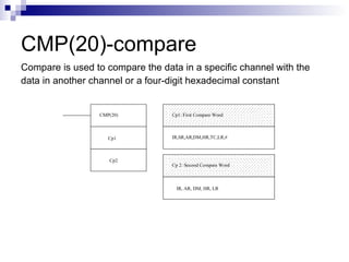
  • 25. CMP(20)-compare Compare is used to compare the data in a specific channel with the data in another channel or a four-digit hexadecimal constant CMP(20) Cp1 Cp2 Cp1: First Compare Word IR,SR,AR,DM,HR,TC,LR,# Cp 2: Second Compare Word IR, AR, DM, HR, LR
  • 26. Example 25313 TR0 CMP(20) #0020 HR1 25507 ( < ) 25506(=) 10001 10002 Green Light Red Light ADDR OP CODE DATA 0000 LD 25313 0001 OUT TR0 0002 CMP (20) #0020 HR1 0003 AND 25507 0004 OUT 10001 0005 LD TR 0 0006 AND 25506 0007 OUT 10002
  • 27. Add(30) To add data in two different channel ADD(30) Au Ad R Au: Augend Channel IR,SR,AR,DM,HR,TC,LR,# Ad: Addend Channel IR,SR,AR,DM,HR,TC,LR,# R: Result IR,AR,DM,HR,LR
  • 28. The operation: 1. 2. Add #0001 + #1234 = #1235 3. The result: ADD(30) HR000 #1234 HR000 00007 ADDR OP CODE DATA 0000 LD 00007 0001 ADD(30) 0002 HR000 #1234 HR000 0003 END(01) HR000 #0001 #1234 HR000 #1235 HR000 #1235
  • 30.  
  • 31. Continue.. A simple car park control system allows only a maximum of 30 cars parking spaces. Every time a car comes in, an incoming sensor will add 1 and any car that goes out an outgoing sensor will deduct 1. If the car park is occupied with 30 cars at one time, a full sign will be lighted up to inform there is no vacancy. Replace CNTR with ADD and SUB.
  • 32. Exercise Using KEEP instruction to solve these problems instead of normal latching: A sensor is placed outside yellow line that enclosed the robot to provide safety cautions to the user. If the sensor detects someone crossing the yellow line the robot will automatically stop its operation and the siren will on until a reset button is pressed. Then the push button need to be pressed for robot to run again. YELOW LINE ROBOT sensor sensor sensor
  • 34. Exercise 2 An automatic home garage is equipped with sensor 1, S1, that detects the approaching car and will open the garage until sensor 2, S2,detects the whole car body has safely parks inside the garage. Use DIFU and DIFD to solve the problem. S1 S2 Garage Door
  • 36. Exercise 3 A conveyor belt is used to transfer red and blue balls for sorting by initially pressed the start button. A colour sorter system is designed to sort red balls and blue balls. If sensor 1 detects red ball, the ball will be pushed into bin 1 by cylinder 1 (CY1) for 2 seconds. If sensor 2 detects blue ball then the ball will be pushed into bin 2 by cylinder 2 (CY2) for another 2 seconds. If the counter has counted 10 red balls, then red light is on and when counter has counted 10 blue balls then green light is on. When either lights is on the conveyor stops the transferring of the balls. The conveyor will start again when reset button is pressed to empty the adder of full ball and the system restart. Use ADD, MOV, CMP instead of CNT.
  • 37. Assignment A conveyor belt is used to transfer red and blue balls for sorting by initially pressed the start button. A color sorter system is designed to sort red balls and blue balls. If sensor 1 detects red ball, the ball will be pushed into bin 1 by cylinder 1 (CY1).If sensor 2 detects blue ball then the ball will be pushed into bin 2 by cylinder 2 (CY2). If the counter has counted 10 red balls, then red light is on and when counter has counted 10 blue balls then green light is on. When either lights is on the conveyor stops the transferring of the balls. Use CNT instead of ADD and SUB. Assume traveling time for cylinder from original position to full extension(vice versa is 0.2 sec) and all cylinder is single acting cylinder. All cylinder will go back to its original position after transferring the ball.
  • 38. Assignment Two different item need to be sort out. It is been placed along a conveyor belt. Conveyor belt will turn on when sensor 1 detect the first item present on that conveyor belt at its origin. When sensor 2 detect item A, it will be transferred by single acting cylinder, CY1 to first path. When LS1 detect the full extension of CY1,it will return to its initial position. When sensor 3 detect item B,it will be transferred by single acting cylinder,CY2 to second path.When LS2 detect full extension of CY2,it will return to its intial position.If the counter has counted 30 item A, green light will be on.If the counter counted 30 item B,blue light will be on.When one of the counter has count 30 item no matter item A or item B, the conveyor belt will be turn off. It will be turn on again when the adder of full ball is reset to zero then the system will restart again. Use DIFU, ADD, MOV, and CMP instead of CNT.
  • 39. BREAK TIME ! Any Questions So far???