Plc (programming)
Download as PPTX, PDF59 likes33,245 views

The document discusses different types of programming languages used in programmable logic controllers (PLCs), including ladder logic, Boolean logic, and Grafcet. It provides details on each language and describes common instruction sets used, such as timers, counters, arithmetic, and data manipulation. The document also covers IEC 61131-3 standard languages like ladder diagrams, function block diagrams, instruction lists, structured text, and sequential function charts. Finally, it discusses PLC architecture and different I/O bus network standards and configurations.


Plc (programming)
- 1. 1
- 2. TYPES OF PLC LANGUAGES The three types of programming languages used in PLCs are: • Ladder • Boolean • Grafcet 2
- 3. LADDER LANGUAGE 3
- 4. Enhanced functional block format 4
- 5. PLC Instruction Set Classifications 5
- 6. These instruction categories include: • ladder relay • timing • counting • program/flow control • arithmetic • data manipulation • data transfer • special function (sequencers) • network communication 6
- 7. BOOLEAN Some PLC manufacturers use Boolean language, also called Boolean mnemonics, to program a controller. 7
- 8. GRAFCET •Grafcet (Graphe Fonctionnel de Commande Étape Transition) is a symbolic, graphic language, which originated in France, that represents the control program as steps or stages in the machine or process. •In fact, the English translation of Grafcet means “step transition function charts.” •As the IEC 1131 standard’s sequential function charts (SFCs), which allow several PLC languages to be used in one control program. 8
- 9. 9
- 10. Grafcet translation 10
- 11. LADDER DIAGRAM FORMAT •A ladder rung is TRUE when it has logic continuity. •Logic continuity exists when power flows through the rung from left to right. •The execution of logic events that enable the output provide this continuity. 11
- 12. Illustration of several different continuity paths in a ladder rung 12
- 13. Monitoring device showing (a)Power continuity through the rung—inputs 11 and 12 are ON, turning output 40 ON. (b)Power continuity through only input 12, thus output 40 is not ON. 13
- 14. Functional block instructions (a) one enable line and one output (b) one enable line, a start timing command, and two outputs. 14
- 15. A functional block instruction that is always enabled To make a block active at all times without any driving logic, the user can omit all contact logic and place a continuity line in the block during programming 15
- 16. The ladder rung matrix •It determines the maximum number of ladder contact elements that can be used to program a rung. •The size of this matrix differs among both PLC manufacturers and the programming devices used 16
- 17. Ladder matrix (a)functional block instructions (b)Enhanced ladder format functional instructions. 17
- 18. •One rule, which is present in almost all PLCs, prevents reverse (i.e., right-to-left) power flow in a ladder rung. •PLC logic does not allow reverse power to avoid sneak paths. •Sneak paths occur when power flows in a reverse direction through an undesired field device, thus completing a continuity path. •If a PLC’s logic requires reverse power flow, the user must reprogram the rung with forward power flow to all contact elements. 18
- 19. 19
- 20. 20
- 21. EXAMINE-ON/NORMALLY OPEN EXAMINE-OFF/NORMALLY CLOSED 21
- 22. OUTPUT COIL 22
- 23. LATCH/UNLATCH OUTPUT COIL 23
- 24. ONE-SHOT OUTPUT 24
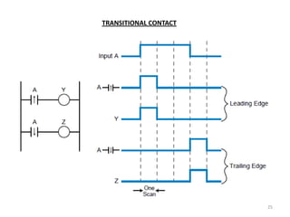
- 25. TRANSITIONAL CONTACT 25
- 26. Ladder rung where all outputs turn ON in the same scan 26
- 27. Ladder rung where the outputs turn ON in different scans 27
- 28. TIMER INSTRUCTIONS 28
- 29. 29
- 30. Hardwired circuit with time-delay and instantaneous contacts 30
- 31. ON-DELAY ENERGIZE/ DE-ENERGIZE TIMER 31
- 32. OFF-DELAY ENERGIZE/ DE-ENERGIZE TIMER 32
- 33. COUNTER INSTRUCTIONS 33
- 34. Counter function block with up, down, and reset counter instructions 34
- 36. Program/flow control instructions •They direct the flow of operations, as well as the execution of instructions, within a ladder program. •They perform these functions using branching and return instructions, which are executed when certain already programmed control logic conditions occur. 36
- 37. 37
- 38. 38
- 39. Example of an MCR instruction 39
- 40. Example of a jump to instruction 40
- 41. PLC with assigned subroutines at the end of the program 41
- 42. User-created subroutine area 42
- 43. ARITHMETIC INSTRUCTIONS 43
- 44. Arithmetic Instructions (a) Coil (b) contact (c) block format. 44
- 46. DATA TRANSFER INSTRUCTIONS 46
- 48. A sequencer (SEQ) block 48
- 49. Sequencer instruction block 49
- 50. DIAGNOSTICS A diagnostics (DIAG) block instruction compares two memory blocks. 50
- 51. PID functional block 51
- 52. 52
- 53. Operation of a network output coil and a network contact instructions. Note that contact 20 in PLC #2 is a local contact 53
- 54. Network Send/Receive 54
- 55. BOOLEAN MNEMONICS It is a PLC language based primarily on the Boolean operators AND, OR, and NOT. 55
- 56. INTRODUCTION TO THE IEC 1131 The International Electrotechnical Commission (IEC) SC65B-WG7 committee developed the IEC 1131 standard in an effort to standardize programmable controllers. One of the committee’s objectives was to create a common set of PLC instructions that could be used in all PLCs. 56
- 57. It defines two graphical languages and two text-based languages for use in PLC programming. The graphical languages use symbols to program control instructions, while the text-based languages use character strings to program instructions. Graphical languages • ladder diagrams (LD) • function block diagram (FBD) Text-based languages • instruction list (IL) • structured text (ST) 57
- 58. The five IEC 61131-3 Programming languages Function Block Diagram (FBD) graphical languages Sequential Flow Chart (SFC) AUTO CALC1 START STEP DI CALC PUMP V IN1 OUT >=1 DO T1 MAN_ON V N ACTION D1 D1_READY STEP A ACT IN2 D ACTION D2 D2_READY T2 N ACTION D3 D3_READY STEP B Ladder Diagram (LD) D ACTION D4 D4_READY CALC1 T3 AUTO CALC PUMP IN1 OUT ACT textual languages Structured Text (ST) IN2 VAR CONSTANT X : REAL := 53.8 ; MAN_ON Z : REAL; END_VAR VAR aFB, bFB : FB_type; END_VAR bFB(A:=1, B:=„OK‟); Instruction List (IL) Z := X - INT_TO_REAL (bFB.OUT1); A: LD %IX1 (* PUSH BUTTON *) IF Z>57.0 THEN aFB(A:=0, B:=“ERR”); ANDN %MX5 (* NOT INHIBITED *) ELSE aFB(A:=1, B:=“Z is OK”); ST %QX2 (* FAN ON *) END_IF 58
- 59. 59
- 60. Limit switch addressed (a) a standard PLC environment (b) an IEC 1131-3 environment 60
- 61. •Ladder diagram language (LD) uses a standardized set of ladder programming symbols to implement control functions. •Instruction list (IL) is a low-level language similar to the machine or assembly language used with microprocessors. This type of language is useful for small applications, as well as applications that require speed optimization of the program or a specific routine in the program. 61
- 62. 62
- 63. •Structured text (ST) is a high-level language that allows structured programming, meaning that many complex tasks can be broken down into smaller ones. ST resembles a BASIC- or PASCAL-type computer language. Structured text programming is particularly suited to applications involving data handling, computational sorting, and intensive mathematical applications utilizing floating-point values. ST is also the best language for implementing artificial intelligence (AI) computations, fuzzy logic, and decision making. 63
- 64. 64
- 65. SEQUENTIAL FUNCTION CHARTS (SFC) Sequential functional chart, or SFC, is a graphical “language” that provides a diagrammatic representation of control sequences in a program. Basically, sequential function chart is a flowchart- like framework that can organize the subprograms or subroutines (programmed in LD, FBD, IL, and/or ST) that form the control program. 65
- 66. The SFC programming framework contains three main elements that organize the control program: • steps A step is a stage in the control process. • transitions After the PLC executes a step/action, it must receive a transition before it will proceed to the next step. • actions Each step may or may not have an action associated with it. An action is a set of control instructions prompting the PLC to execute a certain control function during that step. 66
- 67. Sequential function chart of a mixing process 67
- 68. Comparison of an SFC diagram and a flowchart 68
- 69. Macrostep within an SFC program 69
- 70. Graphic symbols used in SFCs 70
- 71. (a) Level 1 SFC level 2 SFC 71
- 72. PROGRAMMING NORMALLY CLOSED TRANSITIONS 72
- 73. DIVERGENCES AND CONVERGENCES A divergence is when an SFC element has many links going out of it, while a convergence is when an element has many links coming into it. 73
- 74. OR Divergences and Convergences 74
- 75. AND Divergences and Convergences 75
- 76. 76
- 77. General PLC architecture RS 232 Ethernet Real-Time flash serial port ethernet CPU ROM Clock EPROM controller controller extension bus parallel bus buffers fieldbus analog- digital- external Digital controller digital analog Digital Output I/Os Input converters converters signal power signal relays conditioning amplifiers conditioning field bus direct Inputs and Outputs 77
- 78. I/O bus network block diagram 78
- 79. Connection between a PLC, a local area network, and an I/O bus network 79
- 80. TYPES OF I/O BUS NETWORKS I/O bus networks can be separated into two different categories—one that deals with low-level devices that are typical of discrete manufacturing operations and another that handles high-level devices found in process industries. These bus network categories are: • device bus networks • process bus networks 80
- 81. I/O bus network classification diagram 81
- 82. Network and protocol standards 82
- 83. InterBus-S I/O network interface connected to a Siemens PLC 83
- 84. An InterBus-S network with a host controller interface to a PLC 84
- 85. ASI bit-wide device bus network 85
- 86. I/O bus network using the CANbus and ASI networks 86
- 87. Process bus configuration 87
- 88. Bridge connecting low-speed and high-speed Fieldbus networks 88
- 89. Profibus hierarchy 89
- 90. DeviceNet I/O bus port connections 90
- 91. 91
- 92. 92