SlideShare a Scribd company logo
An Introduction
to Networking
Figure 1-1: Basic Networking Concepts


• What Is a Network?
  – A network is a transmission system that connects two
    or more applications running on different computers.


                        Network
                        Network


                                           2
Figure 1-1: Basic Networking Concepts

• Client/Server Applications
   – Most Internet applications are client/server applications
   – Clients receive service from servers
   – The client is often a browser

         Client                                 Server
        Program                                Program


                           Services


Client Computer
                                                   Server Computer
                                               3
The Nine Elements of a
  Network

    Although the idea of “network”
 is simple, you must understand the
nine elements found in most networks
Figure 1-3: Elements of a Network

         Client Application                          Server Application
                              Message (Frame)
                              Message (Frame)

                 Access                         Switch
                  Line                  1.
                                         1.       2
 Client                        Networks connect
                               Networks connect                 Server
Computer            applications on different computers.
                     applications on different computers.      Computer
                Switch
                                                      Switch
                  1
                        Trunk
                        Networks connect computers: 3
                         Networks connect computers:
                         Line
                       2. Clients (fixed and mobile) and
                        2. Clients (fixed and mobile) and
Mobile                             3. Servers
                                    3. Servers
Client                                                           Outside
                                                                  World
                       Wireless
                     Access Point                   Router
                                                          5
Figure 1-3: Elements of a Network

       Client Application                       Server Application
                             Message (Frame)


 Client
                                                          Server
Computer
                                                         Computer
               Switch
                 4.
                  4.                           Switch
     Computers1
     Computers (and routers)
                  (andTrunk
                       routers)                  3
       usually communicate
        usually communicate
                       Line
       by sending messages
Mobile by sending messages
           called frames
            called frames
Client                                                      Outside
                                                             World
                     Wireless
                   Access Point                Router
                                                    6
Figure 1-3: Elements of a Network

       Client Application                          Server Application
            Client
             Client           Message (Frame)
                               Message (Frame)
                                        Sw2 Sends
           Sends      Sw1 Sends          Sw2 Sends
            Sends Sw1 Sends                Frame
                                            Frame
           Frame         Frame
                          Frame
            Frame                         To Sw3
                                           To Sw3
           to Sw1        to Sw2
                          to Sw2
            to Sw1
  Client                            Switch 2
                                    Switch 2
                                                               Server
                                                       Sw3 Sends
                                                        Sw3 Sends
Computer
                                                             Computer
                                                         Frame to
                                                         Frame to
             Switch 1
              Switch 1                                    Server
                                                           Server
                                               Switch 3
                                                Switch 3
                       Trunk
                        Line
Mobile         5.
                5.
Client Switches Forward              Switch                      Outside
       Switches Forward
     Frames Sequentially
      Frames Sequentially              4                          World
                      Wireless
                    Access Point                  Router
                                                        7
Figure 1-5: Ethernet Switch Operation

                   C3- is out Port 15
                   C3- is out Port 15
                                                  D4-47-55-C4-B6-F9
Switching Table
 Switching Table
Port                                    Switch
 Port Host
        Host
10
 10    A1-44-D5-1F-AA-4C
        A1-44-D5-1F-AA-4C
13                    2
       B2-CD-13-5B-E4-65
 13     B2-CD-13-5B-E4-65
15
15
 15
 15    C3-2D-55-3B-A9-4F
        C3-2D-55-3B-A9-4F
        C3-2D-55-3B-A9-4F
        C3-2D-55-3B-A9-4F
16
 16     D4-47-55-C4-B6-F9
         D4-47-55-C4-B6-F9                   Port 15
                                        3

                                        Frame to C3…
                                        Frame to C3…
                Frame to C3…
                Frame to C3…

               1
                                                  C3-2D-55-3B-A9-4F
 A1-44-D5-1F-AA-4C       B2-CD-13-5B-E4-65

      A1- sends a frame to C3-           Switch sends frame to C3-
                                         Switch sends frame to C3-
      A1- sends a frame to C3-
                                                   8
Figure 1-3: Elements of a Network

      Client Application                        Server Application
                             Message (Frame)
                             Message (Frame)

              Access                        Switch
               Line                           2
  Client
                                                          Server
Computer 6.
            6.                                           Computer
               Switch
    Wireless Access
    Wireless Access                             Switch
                 1
    Points Connect
     Points Connect Trunk                         3
   Wireless Stations
    Wireless Stations Line
       to Switches
Mobile to Switches
Client                             Switch                   Outside
                                     4                       World
                    Wireless
                  Access Point                 Router
                                                     9
Figure 1-3: Elements of a Network

         Client Application                         Server Application
                                 Message (Frame)
                                 Message (Frame)

                 Access                       Switch
                  Line                          2
 Client
                                                7.            Server
Computer                                         7.
                                  Routers connect networks Computer
                                   Routers connect networks
                Switch
                                     to the outside world;
                                                      Switch
                                      to the outside world;
                  1
                         Trunk    Treated just like computers
                                                         3
                                  Treated just like computers
                          Line         in single networks
                                        in single networks
Mobile
Client                               Switch                     Outside
            Yes, single networks can   4                         World
                       Wireless
                 contain routers
                     Access Point                  Router
                                                        10
Figure 1-3: Elements of a Network

       Client Application                        Server Application
                             8. Access Lines
                              8. Access Lines
                             Message (Frame)
                             Message (Frame)
                            Connect Computers
                            Connect Computers
               Access          to Switches
                                to Switches
                                             Switch
                Line
                                               2
 Client
                                                            Server
Computer
                                                           Computer
              Switch
                                                 Switch
                1
                       Trunk                       3
                        Line
Mobile
Client                              Switch                   Outside
    9. Trunk Lines Connect
     9. Trunk Lines Connect           4                       World
                     Wireless
   Switches to Switches and
   Switches to Switches and
      Switches to Routers Point
                   Access
       Switches to Routers                      Router
                                                      11
Figure 1-4: Packet Switching and Multiplexing

                       Breaking Communications into
                         Small Messages is Called
                        Packet Switching, even if the
                          Messages are Frames                AC
                AC
  Client                                                AC          Server
                     AC
Computer A                                                        Computer C
                              AC    BD    AC
                               Trunk Line
                                                    BD
             Access
              Line Multiplexed Packets                   BD
          BD
                    Share Trunk Lines

Mobile Client             So Packet Switching                     Router D
Computer B           Reduces the Cost of Trunk Lines


                                                             12
Figure 1-8: LANs Versus WANs

Characteristics
Characteristics   LANs
                   LANs                      WANs
                                              WANs
Scope
Scope             For transmission within
                   For transmission within   For transmission
                                              For transmission
                  a site. Campus,
                   a site. Campus,           between sites
                                              between sites
                  building, and SOHO
                   building, and SOHO
                  (Small Office or Home
                   (Small Office or Home
                  Office) LANs
                   Office) LANs


     Building
     Building                                    Campus
                                                 Campus
      LAN
       LAN           Wide Area                    LAN
                                                   LAN
                      Network

                     Home
                     Home
                      LAN
                       LAN
                                               13
Figure 1-8: LANs Versus WANs

Characteristics             LANs                      WANs
Cost per bit Transmitted    Low                       High
                            Unshared 100 Mbps         Shared 128 kbps to
                            to a gigabit per          several megabits per
Typical Speed               second to each            second trunk line
                            desktop. Even faster      speeds
                            trunk line speeds.


     It’s simple economics. If the cost per unit is higher, the number
     of units demanded will be lower.
     Corporations cannot afford high-speed for most of their WAN
     transmission
                                                         14
Figure 1-8: LANs Versus WANs


Characteristics    LANs                 WANs
                                         WANs
                   On own premises, so Must use a carrier with
                    On own premises, so Must use a carrier with
Management
Management         firm builds and
                    firm builds and     rights of way for
                                         rights of way for
                   manages its own LAN transmission in public
                    manages its own LAN transmission in public
                   or outsources the
                    or outsources the   Area. Carrier handles
                                         Area. Carrier handles
                   Work
                    Work                most work but
                                         most work but
                                        Charges a high price.
                                         Charges a high price.

Choices
Choices            Unlimited
                   Unlimited             Only those offered by
                                          Only those offered by
                                         carrier
                                          carrier


                                            15
Figure 1-9: Local Area Network (LAN) in a
         Large Building

                          Wall Jack           Workgroup Switch 2
              Client


              Server                  Workgroup Switch 1

                              Wall Jack

        To       Router                   Core Switch
       WAN


Frames from the client to the server go through Workgroup Switch 2,
through the Core Switch, through Workgroup Switch 1, and then to the
server                                                16
Figure 1-11: Internets

• Single LANs Versus Internets
  – In single networks (LANs and WANs), all devices
    connect to one another by switches—our focus so far.

  – In contrast, an internet is a group of networks connected
    by routers so that any application on any host on any
    single network can communicate with any application on
    any other host on any other network in the internet.

     Application                            Application

           LAN
            LAN             WAN
                            WAN               LAN
                                               LAN
                   Router          Router
                                              17
Figure 1-11: Internets

• Internet Components
                                             Host
  – All computers in an internet are called hosts
  – Clients as well as servers
                                            PDA
 Client PC                                 (Host)
  (Host)                                            VoIP Phone
                                                      (Host)


                              Internet
                               Internet

    Server
    (Host)                        Cat           Cellphone
                               (Ignores          (Host)
                               Internet)
                                              18
Figure 1-11: Internets
• Hosts Have Two Addresses
• IP Address
  – This is the host’s official address on its internet
  – 32 bits long
  – Expressed for people in dotted decimal notation (e.g.,
    128.171.17.13)
• Single-Network Addresses
  – This is the host’s address on its single network
  – Ethernet addresses, for instance, are 48 bits long
  – Expressed in hexadecimal notation (e.g., AF-23-9B-
    E8-67-47)
                                           19
Figure 1-11: Internets


• Networks are connected by devices called routers
  – Switches provide connections within networks, while
    routers provide connections between networks in an
    internet.

• Frames and Packets
  – In single networks, message are called frames
  – In internets, messages are called packets


                                            20
Figure 1-11: Internets
                                                    Packet
                                                    Packet
                                                    Frame
• Packets are carried within frames
  – One packet is transmitted from the source host to the
    destination host across the internet
     • Its IP destination address is that of the destination
       host


           LAN
            LAN            WAN
                           WAN                 LAN
                                                LAN
                  Router             Router
                                               21
Figure 1-14: The Internet, internets,
       Intranets, and Extranets

• Lower-case internet
  – Any internet

• Upper-case Internet
  – The global Internet

• Intranet
  – An internet restricted to users within a single company

• Extranet
  – A group of resources that can be accessed by authorized
    people in a group of companies
                                             22
Figure 1-23: Firewall and Hardened Hosts


            Allowed Legitimate        Border
                  Packet                                   Attacker
                                      Firewall
                                              The
Hardened                                    Internet
 Server

                       Border firewall
                       Border firewall    Legitimate
                        should pass
                         should pass       Packet
                    legitimate packets
                     legitimate packets
Hardened                                               Legitimate
Client PC                                                Host
                                      Internal
                       Log File       Corporate
                                      Network

                                                 23
Figure 1-23: Firewall and Hardened Hosts

Hardened            Border firewall
 Server              Border firewall               Attack
                  should deny (drop)
                   should deny (drop)   Border     Packet      Attacker
                        and log
                         and log        Firewall
                    attack packets
                     attack packets
                                                 The
                                               Internet
 Hardened
 Client PC

                              Denied
                              Attack
                              Packet                      Legitimate
                                                            Host
                                         Internal
                            Log File     Corporate
                                         Network

                                                   24
Figure 1-23: Firewall and Hardened Hosts

             Hardened
             Hardened
              Server                               Attack
               Server   Attack          Border     Packet   Attacker
                        Packet          Firewall

                                                 The
                                               Internet

                                       Hosts should
                                        Hosts should
                   Attack     Denied be hardened
                   Packet               be hardened
Hardened
Hardened                      Attack
                                  against attack packets
                                   against attack packets
Client PC
 Client PC                    Packet that get through
                                      that get through Legitimate
                                                          Host
                                            Internal
                            Log File        Corporate
                                            Network

                                                   25

More Related Content

PPT
Switching systems lecture2
PPT
Switching systems lecture6
PDF
Wireless lecture1
PPT
Digital network lecturer5
PPT
Switching systems lecture5
PDF
PPTX
It2402 mobile communication unit2
DOCX
Evolution of switching systems
Switching systems lecture2
Switching systems lecture6
Wireless lecture1
Digital network lecturer5
Switching systems lecture5
It2402 mobile communication unit2
Evolution of switching systems

What's hot (20)

PPS
Introduction to Intelligent Network
PPT
Switching systems lecture4
PPTX
SWITCHING SYSTEM SOFTWARE
PDF
Auto default gateway settings for virtual
PDF
Mobile Communication
PPTX
Mobile Computing (Part-2)
PDF
CS8601 MOBILE COMPUTING
PDF
PDF
A prototyping of software defined radio using qpsk modulation
PDF
IT6601 MOBILE COMPUTING
PPT
Switching systems lecture7
PPT
Chapter 8
PPTX
4G Handovers || LTE Handovers ||
PPT
C C N A Day5
PDF
Mobile Communication
PPT
Digital network lecturer2
PDF
Division multiple access technology
PDF
IT6601 Mobile Computing Unit IV
PPTX
It2402 mobile communication unit3
PDF
WLAN - IEEE 802.11
Introduction to Intelligent Network
Switching systems lecture4
SWITCHING SYSTEM SOFTWARE
Auto default gateway settings for virtual
Mobile Communication
Mobile Computing (Part-2)
CS8601 MOBILE COMPUTING
A prototyping of software defined radio using qpsk modulation
IT6601 MOBILE COMPUTING
Switching systems lecture7
Chapter 8
4G Handovers || LTE Handovers ||
C C N A Day5
Mobile Communication
Digital network lecturer2
Division multiple access technology
IT6601 Mobile Computing Unit IV
It2402 mobile communication unit3
WLAN - IEEE 802.11
Ad

Viewers also liked (8)

PPT
5 intro to networking
PPT
"Internet Protocol Suite" prepared by Szymon M. from Poland
PPTX
Structure of url, uniform resource locator
PPT
Network layer and circuit switching
PPT
Url Presentation
PPTX
Circuit Switching
PPTX
Switching
5 intro to networking
"Internet Protocol Suite" prepared by Szymon M. from Poland
Structure of url, uniform resource locator
Network layer and circuit switching
Url Presentation
Circuit Switching
Switching
Ad

Similar to Chapter1 modified (20)

PDF
คู่มือการตั้งค่าLan
PPTX
الشبكات ماجد الصم
PDF
Wireless network basics
PPT
Chapter09
PDF
Lecture03 H
PPTX
Basic networking 07-2012
PDF
CBSE XII Communication And Network Concepts
PPT
PDF
Manika
DOCX
PDF
PPT
VOICE
PDF
Pharo Networking by Example
PPT
BASIC CONCEPTS OF COMPUTER NETWORKS
PPT
Cis82 e2-1-packet forwarding
DOC
Client server-architecture-1229147658096208-1
PPT
Materi Perkuliahan Jaringan Komputer Teknik Informatika Chapter 2
PPT
Switches module 2
PPT
Np unit1
PDF
Osi 7 layer
คู่มือการตั้งค่าLan
الشبكات ماجد الصم
Wireless network basics
Chapter09
Lecture03 H
Basic networking 07-2012
CBSE XII Communication And Network Concepts
Manika
VOICE
Pharo Networking by Example
BASIC CONCEPTS OF COMPUTER NETWORKS
Cis82 e2-1-packet forwarding
Client server-architecture-1229147658096208-1
Materi Perkuliahan Jaringan Komputer Teknik Informatika Chapter 2
Switches module 2
Np unit1
Osi 7 layer

Recently uploaded (20)

PPTX
cloud_computing_Infrastucture_as_cloud_p
PDF
August Patch Tuesday
PDF
Spectral efficient network and resource selection model in 5G networks
PDF
Approach and Philosophy of On baking technology
PDF
Unlocking AI with Model Context Protocol (MCP)
PDF
Per capita expenditure prediction using model stacking based on satellite ima...
PPT
Teaching material agriculture food technology
PDF
gpt5_lecture_notes_comprehensive_20250812015547.pdf
PPTX
Machine Learning_overview_presentation.pptx
PPTX
OMC Textile Division Presentation 2021.pptx
PPTX
Tartificialntelligence_presentation.pptx
PPTX
SOPHOS-XG Firewall Administrator PPT.pptx
PDF
Machine learning based COVID-19 study performance prediction
PDF
Profit Center Accounting in SAP S/4HANA, S4F28 Col11
PDF
Univ-Connecticut-ChatGPT-Presentaion.pdf
PDF
Network Security Unit 5.pdf for BCA BBA.
PPTX
Digital-Transformation-Roadmap-for-Companies.pptx
PPTX
Programs and apps: productivity, graphics, security and other tools
PDF
NewMind AI Weekly Chronicles - August'25-Week II
PDF
Building Integrated photovoltaic BIPV_UPV.pdf
cloud_computing_Infrastucture_as_cloud_p
August Patch Tuesday
Spectral efficient network and resource selection model in 5G networks
Approach and Philosophy of On baking technology
Unlocking AI with Model Context Protocol (MCP)
Per capita expenditure prediction using model stacking based on satellite ima...
Teaching material agriculture food technology
gpt5_lecture_notes_comprehensive_20250812015547.pdf
Machine Learning_overview_presentation.pptx
OMC Textile Division Presentation 2021.pptx
Tartificialntelligence_presentation.pptx
SOPHOS-XG Firewall Administrator PPT.pptx
Machine learning based COVID-19 study performance prediction
Profit Center Accounting in SAP S/4HANA, S4F28 Col11
Univ-Connecticut-ChatGPT-Presentaion.pdf
Network Security Unit 5.pdf for BCA BBA.
Digital-Transformation-Roadmap-for-Companies.pptx
Programs and apps: productivity, graphics, security and other tools
NewMind AI Weekly Chronicles - August'25-Week II
Building Integrated photovoltaic BIPV_UPV.pdf

Chapter1 modified

  • 2. Figure 1-1: Basic Networking Concepts • What Is a Network? – A network is a transmission system that connects two or more applications running on different computers. Network Network 2
  • 3. Figure 1-1: Basic Networking Concepts • Client/Server Applications – Most Internet applications are client/server applications – Clients receive service from servers – The client is often a browser Client Server Program Program Services Client Computer Server Computer 3
  • 4. The Nine Elements of a Network Although the idea of “network” is simple, you must understand the nine elements found in most networks
  • 5. Figure 1-3: Elements of a Network Client Application Server Application Message (Frame) Message (Frame) Access Switch Line 1. 1. 2 Client Networks connect Networks connect Server Computer applications on different computers. applications on different computers. Computer Switch Switch 1 Trunk Networks connect computers: 3 Networks connect computers: Line 2. Clients (fixed and mobile) and 2. Clients (fixed and mobile) and Mobile 3. Servers 3. Servers Client Outside World Wireless Access Point Router 5
  • 6. Figure 1-3: Elements of a Network Client Application Server Application Message (Frame) Client Server Computer Computer Switch 4. 4. Switch Computers1 Computers (and routers) (andTrunk routers) 3 usually communicate usually communicate Line by sending messages Mobile by sending messages called frames called frames Client Outside World Wireless Access Point Router 6
  • 7. Figure 1-3: Elements of a Network Client Application Server Application Client Client Message (Frame) Message (Frame) Sw2 Sends Sends Sw1 Sends Sw2 Sends Sends Sw1 Sends Frame Frame Frame Frame Frame Frame To Sw3 To Sw3 to Sw1 to Sw2 to Sw2 to Sw1 Client Switch 2 Switch 2 Server Sw3 Sends Sw3 Sends Computer Computer Frame to Frame to Switch 1 Switch 1 Server Server Switch 3 Switch 3 Trunk Line Mobile 5. 5. Client Switches Forward Switch Outside Switches Forward Frames Sequentially Frames Sequentially 4 World Wireless Access Point Router 7
  • 8. Figure 1-5: Ethernet Switch Operation C3- is out Port 15 C3- is out Port 15 D4-47-55-C4-B6-F9 Switching Table Switching Table Port Switch Port Host Host 10 10 A1-44-D5-1F-AA-4C A1-44-D5-1F-AA-4C 13 2 B2-CD-13-5B-E4-65 13 B2-CD-13-5B-E4-65 15 15 15 15 C3-2D-55-3B-A9-4F C3-2D-55-3B-A9-4F C3-2D-55-3B-A9-4F C3-2D-55-3B-A9-4F 16 16 D4-47-55-C4-B6-F9 D4-47-55-C4-B6-F9 Port 15 3 Frame to C3… Frame to C3… Frame to C3… Frame to C3… 1 C3-2D-55-3B-A9-4F A1-44-D5-1F-AA-4C B2-CD-13-5B-E4-65 A1- sends a frame to C3- Switch sends frame to C3- Switch sends frame to C3- A1- sends a frame to C3- 8
  • 9. Figure 1-3: Elements of a Network Client Application Server Application Message (Frame) Message (Frame) Access Switch Line 2 Client Server Computer 6. 6. Computer Switch Wireless Access Wireless Access Switch 1 Points Connect Points Connect Trunk 3 Wireless Stations Wireless Stations Line to Switches Mobile to Switches Client Switch Outside 4 World Wireless Access Point Router 9
  • 10. Figure 1-3: Elements of a Network Client Application Server Application Message (Frame) Message (Frame) Access Switch Line 2 Client 7. Server Computer 7. Routers connect networks Computer Routers connect networks Switch to the outside world; Switch to the outside world; 1 Trunk Treated just like computers 3 Treated just like computers Line in single networks in single networks Mobile Client Switch Outside Yes, single networks can 4 World Wireless contain routers Access Point Router 10
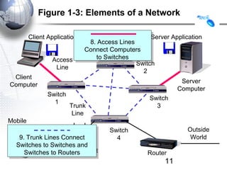
  • 11. Figure 1-3: Elements of a Network Client Application Server Application 8. Access Lines 8. Access Lines Message (Frame) Message (Frame) Connect Computers Connect Computers Access to Switches to Switches Switch Line 2 Client Server Computer Computer Switch Switch 1 Trunk 3 Line Mobile Client Switch Outside 9. Trunk Lines Connect 9. Trunk Lines Connect 4 World Wireless Switches to Switches and Switches to Switches and Switches to Routers Point Access Switches to Routers Router 11
  • 12. Figure 1-4: Packet Switching and Multiplexing Breaking Communications into Small Messages is Called Packet Switching, even if the Messages are Frames AC AC Client AC Server AC Computer A Computer C AC BD AC Trunk Line BD Access Line Multiplexed Packets BD BD Share Trunk Lines Mobile Client So Packet Switching Router D Computer B Reduces the Cost of Trunk Lines 12
  • 13. Figure 1-8: LANs Versus WANs Characteristics Characteristics LANs LANs WANs WANs Scope Scope For transmission within For transmission within For transmission For transmission a site. Campus, a site. Campus, between sites between sites building, and SOHO building, and SOHO (Small Office or Home (Small Office or Home Office) LANs Office) LANs Building Building Campus Campus LAN LAN Wide Area LAN LAN Network Home Home LAN LAN 13
  • 14. Figure 1-8: LANs Versus WANs Characteristics LANs WANs Cost per bit Transmitted Low High Unshared 100 Mbps Shared 128 kbps to to a gigabit per several megabits per Typical Speed second to each second trunk line desktop. Even faster speeds trunk line speeds. It’s simple economics. If the cost per unit is higher, the number of units demanded will be lower. Corporations cannot afford high-speed for most of their WAN transmission 14
  • 15. Figure 1-8: LANs Versus WANs Characteristics LANs WANs WANs On own premises, so Must use a carrier with On own premises, so Must use a carrier with Management Management firm builds and firm builds and rights of way for rights of way for manages its own LAN transmission in public manages its own LAN transmission in public or outsources the or outsources the Area. Carrier handles Area. Carrier handles Work Work most work but most work but Charges a high price. Charges a high price. Choices Choices Unlimited Unlimited Only those offered by Only those offered by carrier carrier 15
  • 16. Figure 1-9: Local Area Network (LAN) in a Large Building Wall Jack Workgroup Switch 2 Client Server Workgroup Switch 1 Wall Jack To Router Core Switch WAN Frames from the client to the server go through Workgroup Switch 2, through the Core Switch, through Workgroup Switch 1, and then to the server 16
  • 17. Figure 1-11: Internets • Single LANs Versus Internets – In single networks (LANs and WANs), all devices connect to one another by switches—our focus so far. – In contrast, an internet is a group of networks connected by routers so that any application on any host on any single network can communicate with any application on any other host on any other network in the internet. Application Application LAN LAN WAN WAN LAN LAN Router Router 17
  • 18. Figure 1-11: Internets • Internet Components Host – All computers in an internet are called hosts – Clients as well as servers PDA Client PC (Host) (Host) VoIP Phone (Host) Internet Internet Server (Host) Cat Cellphone (Ignores (Host) Internet) 18
  • 19. Figure 1-11: Internets • Hosts Have Two Addresses • IP Address – This is the host’s official address on its internet – 32 bits long – Expressed for people in dotted decimal notation (e.g., 128.171.17.13) • Single-Network Addresses – This is the host’s address on its single network – Ethernet addresses, for instance, are 48 bits long – Expressed in hexadecimal notation (e.g., AF-23-9B- E8-67-47) 19
  • 20. Figure 1-11: Internets • Networks are connected by devices called routers – Switches provide connections within networks, while routers provide connections between networks in an internet. • Frames and Packets – In single networks, message are called frames – In internets, messages are called packets 20
  • 21. Figure 1-11: Internets Packet Packet Frame • Packets are carried within frames – One packet is transmitted from the source host to the destination host across the internet • Its IP destination address is that of the destination host LAN LAN WAN WAN LAN LAN Router Router 21
  • 22. Figure 1-14: The Internet, internets, Intranets, and Extranets • Lower-case internet – Any internet • Upper-case Internet – The global Internet • Intranet – An internet restricted to users within a single company • Extranet – A group of resources that can be accessed by authorized people in a group of companies 22
  • 23. Figure 1-23: Firewall and Hardened Hosts Allowed Legitimate Border Packet Attacker Firewall The Hardened Internet Server Border firewall Border firewall Legitimate should pass should pass Packet legitimate packets legitimate packets Hardened Legitimate Client PC Host Internal Log File Corporate Network 23
  • 24. Figure 1-23: Firewall and Hardened Hosts Hardened Border firewall Server Border firewall Attack should deny (drop) should deny (drop) Border Packet Attacker and log and log Firewall attack packets attack packets The Internet Hardened Client PC Denied Attack Packet Legitimate Host Internal Log File Corporate Network 24
  • 25. Figure 1-23: Firewall and Hardened Hosts Hardened Hardened Server Attack Server Attack Border Packet Attacker Packet Firewall The Internet Hosts should Hosts should Attack Denied be hardened Packet be hardened Hardened Hardened Attack against attack packets against attack packets Client PC Client PC Packet that get through that get through Legitimate Host Internal Log File Corporate Network 25