SlideShare a Scribd company logo
Basic Structure of Computers: Computer Types, Functional
units, Basic operational concepts, Bus structures, Software,
Performance, multiprocessors and multi computers,
Computer Generations, Von- Neumann Architecture.
COMPUTER TYPES
• COMPUTER: is an electronic device which takes input, process it and
gives output.
• The following are the various types of computers
• 1. Personal computers: These are general purpose computers
that are widely used in home, schools, colleges, business, offices etc.
• 2. Notebook computers (laptops): These are the compact version
of personal computers. These are portable.
• 3. Workstations: These computers give more performance than
PC’s. They are used for scientific purposes.
Contd ….
4. Mainframes: These computers have more storage and faster
than workstations. These computers can handle large number of users
and used in business data processing.
5. Super Computers: These are fastest computers that are used for
large scale numerical calculations required in weather forecasting and
aircraft design.
6. Hand Held Computer: It is also called a PDA (Personal Digital
Assistant). A computer that fits into a pocket, runs on batteries, and is
used while holding the unit in your hand. Typically used as an
appointment book, address book, calculator and notepad.
FUNCTIONAL UNITS
• A Computer consists of 5 main parts as shown below
Figure Basic Functional units of a Computer
FUNCTIONAL UNITS
1. Input Unit: Computers accept input through input units. Eg: Keyboard,
Mouse etc.
2. Memory Unit:
The function of memory unit is to store programs and data.
There are two classes of storage, primary storage and secondary
storage.
Primary Memory:
Primary memory is the fast memory
The memory consists of large number of semiconductor storage cells.
Each cell can store one bit of data.
These cells are read or written in groups of fixed size called words.
FUNCTIONAL UNITS
• A distinct address is associated with each word location.
• Addresses are the numbers that identify successive locations.
• The number of bits in a word is called word length. It typically ranges from
16 to 64 bits.
• Memory in which any location can be reached in short and fixed amount of
time after specifying its address is called Random Access Memory (RAM).
• The time required to access one word is called memory access time.
• Secondary Memory:
• Secondary memory is used when large amount of data and many programs
needs to be stored.
Eg: Magnetic disks and tapes, Optical disks (CD- ROMs), Pen drives etc.
Continuation …
3. Arithmetic Logic Unit: Performs arithmetic and logic operations
such as addition, multiplication, AND, OR etc.
4. Output Unit: Its function is to send processed result to the
outside world.
5. Control Unit: Controls all the activities in a computer by passing
control signals.
BASIC OPERATIONAL CONCEPTS
An Instruction consists of 2 parts
1) Operation code (Op code) and 2) Operands.
Figure 1.2 Instruction format
• The data/operands are stored in memory.
• The individual instructions are brought from the memory to the processor.
• Processor performs the specified operation.
• Let us see a typical instruction
ADD LOCA, R0
Opcode Operands
BASIC OPERATIONAL CONCEPTS
ADD LOCA, R0
• This instruction is an addition operation. The following are the steps
to execute the instruction.
• Step 1: Fetch the instruction from main-memory into the processor.
• Step 2: Fetch the operand at location LOCA from main-memory into
the processor.
• Step 3: Add the memory operand (i.e. fetched contents of LOCA) to
the contents of register R0.
• Step 4: Store the result (sum) in R0.
Contd ….
• • The same instruction can be realized using 2 instructions as:
• Load LOCA, R1
• Add R1, R0
• • The following are the steps to execute the instruction:
• Step 1: Fetch the instruction from main-memory into the processor.
• Step 2: Fetch the operand at location LOCA from main-memory into the
register R1.
• Step 3: Add the content of Register R1 and the contents of register R0.
• Step 4: Store the result (sum) in R0.
Contd …
Contd ….
Main parts of processor:
• The figure shows connection between the processor and memory. In
addition to the ALU and CU, the processor contains a number of registers used for
several different purposes.
• IR (Instruction Register): Holds the instruction that is currently being executed.
• PC (Program Counter): It contains the memory address of the next instruction to
be fetched and executed.
R0 to Rn-1 (General Purpose Registers): used for storing operands etc.
• MAR (Memory Address Register): It holds the address of memory location to be
accessed.
• MDR (Memory Data Register): It contains the data to be written into or read out
of the address location.
Contd …..
Operating Steps:
(Fetching the Instruction)
1. Execution of program starts when PC is set to point at the first
instruction of the program.
2. Contents of PC are transferred to MAR and READ control signal
sent to the memory.
3. The address word is read out of memory and loaded in to MDR.
4. The contents of MDR are then transferred to the IR and now the
instruction is ready to be executed.
Contd ….
(Fetching operands and performing operation)
5. If the instruction involves operation by the ALU, it is necessary to
obtain the required operands.
6. Operands in the memory are fetched by sending its address to
MAR and READ control signal.
7. When the operands read in to MDR, it is transferred to ALU.
8. ALU performs the desired operations.
Contd ….
• (Storing the result to memory)
• 9. If the result of this operation is to be stored in the memory, the result
is sent to MDR.
• 10. Address of the location where the result is to be stored is sent to MAR
and WRITE control signal is sent.
• 11. The contents of PC are incremented so that PC points to the next
instruction that is to be executed.
• o Normal execution of program may be temporarily interrupted if some
devices require urgent servicing to do this device raises an interrupt signal.
• o An interrupt is a request signal from an I/O device for service by the
processor. The processor provides the requested service by executing
appropriate Interrupt Service Routine.
BUS STRUCTURES
• A bus is a group of lines that serves as a connecting path for several devices.
• A bus may be lines or wires.
• The lines carry data or address or control signal.
• There are 2 types of Bus structures: 1) Single Bus Structure and 2) Multiple Bus
Structure.
• Single Bus Structure
o Because the bus can be used for only one transfer at a time, only 2 units can
actively use the bus at any given time.
o Bus control lines are used to arbitrate multiple requests for use of the bus.
o Advantages:
Low cost &
Flexibility for attaching peripheral devices.
BUS STRUCTURES
Multiple Bus Structure
o Systems that contain multiple buses achieve more concurrency in
operations.
o Two or more transfers can be carried out at the same time.
o Advantage: Better performance.
o Disadvantage: Increased cost.
Contd …..
• The devices connected to a bus vary widely in their speed of operation.
• To synchronize their operational-speed, buffer-registers can be used.
• Buffer Registers are included with the devices to hold the information during
transfers.
• Prevent a high-speed processor from being locked to a slow I/O device
during data transfers.
• For example consider the transfer of character from processor to printer.
• The processor sends the character over bus to the printer buffer. Once the
buffer is loaded, the printer starts printing without intervention by the processor.
• The bus and processor are no longer needed and can be released for other
activity.
• Thus the buffer registers smooth out timing differences among processors,
memory and I/O devices
SOFTWARE
• Software is a collection of programs.
• To run application software, the system must already contain some system
software in the memory.
System software performs the following functions:
• Receiving and interpreting user commands.
• Entering and editing application programs and storing them as files in the
secondary storage.
• Managing the storage and storage of files in the secondary storage devices.
• Running the standard application programs such as word processors,
spreadsheets, or data supplied by the user.
• Controlling I/O units to receive input information and produce output
results.
• Translating programs from source code to object code.
• Linking and running user-written application programs.
Contd …..
Application programs are usually written in high-level programming
language, such as C,C++, Java etc.
A system software program called a compiler translates high-level
language program to a suitable machine language program.
Languages
Computer programming languages are divided in to three categories:
1. High-level languages
2. Assembly languages
3. Machine languages
Contd …….
High-level languages:
• Languages with the highest level of abstraction are called high-level languages.
• They are said to be platform independent; means the same program code can
be converted and run on computers with different microprocessors and
operating systems without modification.
• Examples: C++, Java, and FORTRAN.
Assembly languages:
• Assembly languages are at much lower level of abstraction.
• Each microprocessor has its own assembly language.
• A program written in the assembly language of one microprocessor cannot be
run on a computer that has a different microprocessor.
• Assembly languages are platform dependent.
Contd …..
Machine languages:
• Lowest levels of programming languages are machine languages.
• These languages contain the binary values.
• Programmers do not write programs in machine level language.
• Programs written in high-level language of assembly language are
converted to machine language, which is then executed by the
microprocessor.
• Machine languages are also platform dependent; each
microprocessor has its own machine language.
Contd ….
Translators:
• A program written in high-level language is called as source code.
To convert the source code into machine code, translators are
needed.
• A translator takes a program written in source language as input
and converts it into a program in target language as output.
• It also detects and reports the error during translation.
Roles of translator are
• Translating the high-level language program input into an equivalent
machine language program.
• Providing diagnostic messages wherever the programmer violates
specification of the high-level language program.
Contd …..
Different type of translators
The different types of translator are as follows:
Compiler: Compiler is a translator which is used to convert programs in
high-level language to low-level language. It translates the entire
program and also reports the errors in source program encountered
during the translation.
Figure: Compiler
Contd …..
Assembler
Assembler is a translator which is used to translate the assembly
language code into machine language code.
Figure 1.6 Assembler
Contd …..
Loader:
• In computing, a loader is the part of an operating system that is
responsible for loading programs and libraries.
• It is one of the essential stages in the process of starting a program, as
it places programs into memory and prepares them for execution.
• Loading a program involves reading the contents of the executable file
containing the program instructions into memory, and then carrying out
other required preparatory tasks to prepare the executable for running.
• Once loading is complete, the operating system starts the program by
passing control to the loaded program code.
Contd ….
Linker:
After compilation or assembling process, object code is generated. Linker
links this object code with other required object code or library files to make
it an executable file.
Operating System:
• OS is a large program, or actually a collection of routines , that is used to
control the sharing of and interaction among various computer units.
• In order to understand the basics of operating system, let us consider a
system with one processor, one disk, and one printer.
• First we discuss the steps involved in running the application program.
Assume that the application program is stored in disk.
• First step is to transfer this file in to the memory.
Contd …..
• When the transfer is complete, execution of the program is started.
• Assume that the part of the program’s task involves reading a data file from
the disk in to the memory, performing some computations on the data, and
printing the results.
• When execution of the program reaches the point where the data file is
needed, the program requests the operating system to transfer the data
from the disk to memory.
• The OS performs this task and passes the execution control back to the
application program, which then proceed to perform the required
computation.
• When the computation is completed and the results are ready to be printed,
the application program again sends a request to the OS.
• An OS routine is then executed to cause the printer to print the results.
Contd …..
This above process is illustrated by the time-line diagram as shown in
the fig. below.
PERFORMANCE
• The most important measure of the performance of a computer is
how quickly it can execute programs. The speed with which a
computer executes program is affected by the design of its
hardware. For best performance, it is necessary to design the
compiles, the machine instruction set, and the hardware in a
coordinated way.
• The total time required to execute the program is elapsed time is a
measure of the performance of the entire computer system. It is
affected by the speed of the processor, the disk and the printer. The
time needed to execute a instruction is called the processor time.
Contd …..
• Just as the elapsed time for the execution of a program depends on all
units in a computer system, the processor time depends on the
hardware involved in the execution of individual machine instructions.
This h a r d w a r e comprises the processor and the memory which
are usually connected by the bus as shown in the below figure.
Figure The Processor cache
Contd ….
• The pertinent parts of the fig. c are repeated in fig. d which includes
the cache memory as part of the processor unit.
• Let us examine the flow of program instructions and data between the
memory and the processor. At the start of execution, all program
instructions and the required data are stored in the main memory.
• As the execution proceeds, instructions are fetched one by one over
the bus into the processor, and a copy is placed in the cache later if the
same instruction or data item is needed a second time, it is read
directly from the cache.
• The processor and relatively small cache memory can be fabricated
on a single IC chip. The internal speed of performing the basic steps of
instruction processing on chip is very high and is considerably faster
than the speed at which the instruction and data can be fetched
from the main memory.
Contd …..
• A program will be executed faster if the movement of instructions
and data between the main memory and the processor is
minimized, which is achieved by using the cache.
• For example:- Suppose a number of instructions are executed
repeatedly over a short period of time as happens in a program
loop. If these instructions are available in the cache, they can be
fetched quickly during the period of repeated use. The same applies
to the data that are used repeatedly.
Contd ….
Processor clock
• Processor circuits are controlled by a timing signal called clock.
The clock designer the regular time intervals called clock cycles. To
execute a machine instruction the processor divides the action to be
performed into a sequence of basic steps that each step can be
completed in one clock cycle. The length P of one clock cycle is an
important parameter that affects the processor performance.
• Processor used in today’s personal computer and work station have a
clock rates that range from a few hundred million to over a billion
cycles per second.
Contd ….
Basic performance equation
• We now focus our attention on the processor time component of the total
elapsed time. Let ‘T’ be the processor time required to execute a program
that has been prepared in some high-level language.
• The compiler generates a machine language object program that
corresponds to the source program. Assume that complete execution of the
program requires the execution of N machine cycle language instructions.
• The number N is the actual number of instruction execution and is not
necessarily equal to the number of machine cycle instructions in the
object program. Some instruction may be executed more than once,
which in the case for instructions inside a program loop others may not be
executed all, depending on the input data used.
Contd …..
• Suppose that the average number of basic steps needed to execute
one machine cycle instruction is S, where each basic step is
completed in one clock cycle. If clock rate is ‘R’ cycles per second,
the program execution time is given by
T=N*S/R
this is often referred to as the basic performance equation.
• We must emphasize that N, S & R are not independent parameters
changing one may affect another. Introducing a new feature in the
design of a processor will lead to improved performance only if the
overall result is to reduce the value of T.
Contd …..
Pipelining and super scalar operation: -
• We assume that instructions are executed one after the other. Hence the
value of S is the total number of basic steps, or clock cycles, required to
execute one instruction. A substantial improvement in performance can be
achieved by overlapping the execution of successive instructions using a
technique called pipelining.
Consider Add R1 R2 R3
• This adds the contents of R1 & R2 and places the sum into R3.
• The contents of R1 & R2 are first transferred to the inputs of ALU. After
the addition operation is performed, the sum is transferred to R3. The
processor can read the next instruction from the memory, while the addition
operation is being performed. Then of that instruction also uses, the ALU, its
operand can be transferred to the ALU inputs at the same time that the add
instructions is being transferred to R3.
Contd …..
• In the ideal case if all instructions are overlapped to the maximum degree possible the
execution proceeds at the rate of one instruction completed in each clock cycle.
Individual instructions still require several clock cycles to complete.
• But for the purpose of computing T, effective value of S is 1.
• A higher degree of concurrency can be achieved if multiple instructions pipelines are
implemented in the processor.
• This means that multiple functional units are used creating parallel paths through
which different instructions can be executed in parallel with such an arrangement,
it becomes possible to start the execution of several instructions in every clock
cycle.
• This mode of operation is called superscalar execution. If it can be sustained for a long
time during program execution the effective value of S can be reduced to less
than one.
• But the parallel execution must preserve logical correctness of programs, that is the
results produced must be same as those produced by the serial execution of program
instructions. Now a days may processor are designed in this manner.
Contd …..
Clock rate
These are two possibilities for increasing the clock rate ‘R’.
• Improving the IC technology makes logical circuit faster, which reduces the time
of execution of basic steps. This allows the clock period P, to be reduced and the
clock rate R to be increased.
• Reducing the amount of processing done in one basic step also makes it possible
to reduce the clock period P. however if the actions that have to be performed
by an instructions remain the same, the number of basic steps needed may
increase.
• Increase in the value ‘R’ that are entirely caused by improvements in IC
technology affects all aspects of the processor’s operation equally with the
exception of the time it takes to access the main memory. In the presence of
cache the percentage of accesses to the main memory is small. Hence much of
the performance gain excepted from the use of faster technology can be
realized.
Contd ……
Instruction set CISC & RISC:-
• Simple instructions require a small number of basic steps to execute.
Complex instructions involve a large number of steps. For a
processor that has only simple instruction a large number of
instructions may be needed to perform a given programming task.
This could lead to a large value of ‘N’ and a small
• value of ‘S’ on the other hand if individual instructions perform more
complex operations, a fewer instructions will be needed, leading to a
lower value of N and a larger value of S. It is not obvious if one choice is
better than the other.
• But complex instructions combined with pipelining (effective value of S=
1) would achieve one best performance. However, it is much easier to
implement efficient pipelining in processors with simple instruction
sets.
Contd ……
RISC CISC
Simple instructions taking one cycle. Complex instructions taking multiple
cycle.
Instructions are executed by
hardwired control unit.
Instructions are executed by
microprogrammed control unit.
Few instructions. Many instructions.
Fixed format instructions. Variable format instructions.
Few addressing modes, and most
instructions have register to register
addressing mode.
Many addressing modes.
Multiple register set. Single register set.
Highly pipelined. No pipelined or less pipelined.
Performance measurements
• It is very important to be able to access the performance of a computer,
comp designers use performance estimates to evaluate the effectiveness of
new features.
• The previous argument suggests that the performance of a computer is
given by the execution time T, for the program of interest.
• Inspite of the performance equation being so simple, the evaluation of
‘T’ is highly complex. Moreover the parameters like the clock speed and
various architectural features are not reliable indicators of the expected
performance.
• Hence measurement of computer performance using bench mark
programs is done to make comparisons possible, standardized programs
must be used.
Contd…..
• The performance measure is the time taken by the computer to
execute a given bench mark. Initially some attempts were made to
create artificial programs that could be used as bench mark programs.
But synthetic programs do not properly predict the performance
obtained when real application programs are run.
• A non profit organization called SPEC- system performance evaluation
corporation selects and publishes bench marks.
• The program selected range from game playing, compiler, and
data base applications to numerically intensive programs in
astrophysics and quantum chemistry. In each case, the program is
compiled under test, and the running time on a real computer is
measured. The same program is also compiled and run on one
computer selected as reference.
Contd ……
The ‘SPEC’ rating is computed as follows.
SPEC rating = Running time on the reference computer
Running time on the computer under test
If the SPEC rating = 50
• Means that the computer under test is 50 times as fast as the ultra Sparc This is repeated
for all the programs in the SPEC suit, and the geometric mean of the result is computed.
• Let SPECi be the rating for program ‘i’ in the suite. The overall SPEC rating for the
computer is given by
Where ‘n’ = number of programs in suite.
• Since actual execution time is measured the SPEC rating is a measure of the combined
effect of all factors affecting performance, including the compiler, the OS, the processor,
the memory of comp being tested.
MULTIPROCESSOR & MICROPROCESSORS
• Large computers that contain a number of processor units are called
multiprocessor system.
• These systems either execute a number of different application tasks in parallel or
execute subtasks of a single large task in parallel
• All processors usually have access to all memory locations in such system & hence
they are called shared memory multiprocessor systems.
• The high performance of these systems comes with much increased complexity and
cost.
• In contrast to multiprocessor systems, it is also possible to use an interconnected
group of complete computers to achieve high total computational power. These
computers normally have access to their own memory units when the tasks they are
executing need to communicate data they do so by exchanging messages over a
communication network. This properly distinguishes them from shared memory
multiprocessors, leading to name message-passing multi computer.
COMPUTER – GENERATIONS
Generation in computer terminology is a change in technology a
computer is/was being used. Initially, the generation term was used to
distinguish between varying hardware technologies. But nowadays,
generation includes both hardware and software, which together make
up an entire computer system. There are totally five computer
generations known till date. Each generation has been discussed in
detail along with their time period and characteristics. Here
approximate dates against each generations have been mentioned
which are normally accepted.
Contd ….
Following are the main five generations of computers S.N. Generation &
Description
• First Generation The period of first generation: 1946-1959. Vacuum tube
based.
• Second Generation The period of second generation: 1959-1965. Transistor
based.
• Third Generation The period of third generation: 1965-1971. Integrated
Circuit based.
• Fourth Generation The period of fourth generation: 1971-1980. VLSI
microprocessor based.
• Fifth Generation The period of fifth generation: 1980-onwards. ULSI
microprocessor based
Contd ….
First Generation:
The period of first generation was 1946-1959. The computers of first generation
used vacuum tubes as the basic components for memory and circuitry for CPU (Central
Processing Unit). These tubes, like electric bulbs, produced a lot of heat and were prone
to frequent fusing of the installations, therefore, were very expensive and could be
afforded only by very large organization. In this generation mainly batch processing
operating system were used. Punched cards, paper tape, and magnetic tape were used as
input and output devices. The computers in this generation used machine code as
programming language.
• The main features of first generation are:
Vacuum tube technology , Unreliable , Supported machine language only, Very costly ,
Generated lot of heat Slow, input and output devices ,Huge size, Need of A.C. ,Non-
portable, Consumed lot of electricity
• Some computers of this generation were:
• ENIAC, EDVAC , UNIVAC , IBM-701 , BM-650
Contd …..
Second Generation:
The period of second generation was 1959-1965. In this generation transistors were used that were
cheaper, consumed less power, more compact in size, more reliable and faster than the first
generation machines made of vacuum tubes. In this generation, magnetic cores were used as
primary memory and magnetic tape and magnetic disks as secondary storage devices. In this
generation assembly language and high-level programming languages like FORTRAN, COBOL were
used. The computers used batch processing and multiprogramming operating system.
The main features of second generation are:
• Use of transistors
• Reliable in comparison to first generation computers
• Faster than first generation computers
• Still very costly
• A.C. needed
• Supported machine and assembly languages
Some computers of this generation were:
• IBM 1620 , IBM 7094 , CDC 1604 , CDC 3600 ,UNIVAC 1108
Contd …..
Third Generation:
The period of third generation was 1965-1971. The computers of third generation used
integrated circuits (IC's) in place of transistors. A single IC has many transistors, resistors and
capacitors along with the associated circuitry. The IC was invented by Jack Kilby. This
development made computers smaller in size, reliable and efficient. In this generation remote
processing, time-sharing, multi-programming operating system were used. High-level languages
(FORTRAN-II TO IV, COBOL, PASCAL PL/1, BASIC, ALGOL-68 etc.) were used during this generation.
The main features of third generation are:
IC used ,More reliable in comparison to previous two generations ,Smaller size ,Generated
less heat ,Faster ,Lesser maintenance ,Still costly ,A.C needed ,Consumed lesser electricity,
Supported high-level language
Some computers of this generation were:
• IBM-360 series
• Honeywell-6000 series
• PDP(Personal Data Processor)
• IBM-370/168 TDC-316
Contd …….
Fourth Generation :
The period of fourth generation was 1971-1980. The computers of
fourth generation used Very Large Scale Integrated (VLSI) circuits. VLSI
circuits having about 5000 transistors and other circuit elements and
their associated circuits on a single chip made it possible to have
microcomputers of fourth generation. Fourth generation computers
became more powerful, compact, reliable, and affordable. As a result, it
gave rise to personal computer(PC) revolution. In this generation time
sharing, real time, networks, distributed operating system were used.
All the high-level languages like C, C++, DBASE etc., were used in this
generation.
Contd …..
The main features of fourth generation are:
• VLSI technology used
• Very cheap
• Portable and reliable
• Use of PC's
• Very small size
• Pipeline processing
• No A.C. needed
• Concept of internet was introduced
• Great developments in the fields of networks
• Computers became easily available
Some computers of this generation were:
• DEC 10 STAR 1000
• PDP 11 CRAY-1(Super Computer)
• CRAY-X-MP(Super Computer)
Contd ……
Fifth Generation:
The period of fifth generation is 1980-till date. In the fifth
generation, the VLSI technology became ULSI (Ultra Large Scale
Integration) technology, resulting in the production of microprocessor
chips having ten million electronic components. This generation is
based on parallel processing hardware and AI (Artificial Intelligence)
software. AI is an emerging branch in computer science, which
interprets means and method of making computers think like human
beings. All the high-level languages like C and C++, Java, .Net etc., are
used in this generation.
Contd ….
AI includes:
• Robotics , Neural Networks , Game Playing
• Development of expert systems to make decisions in real life situations.
• Natural language understanding and generation.
The main features of fifth generation are:
• ULSI technology
• Development of true artificial intelligence
• Development of Natural language processing
• Advancement in Parallel Processing
• Advancement in Super conductor technology
• More user friendly interfaces with multimedia features
• Availability of very powerful and compact computers at cheaperrates
Some computer types of this generation are:
• Desktop ,Laptop ,NoteBook , UltraBook ,ChromeBook
Von Neumann architecture
Von-Neumann computer architecture:
Von-Neumann computer architecture design was proposed in 1945.It was later
known as Von-Neumann architecture.
Historically there have been 2 types of Computers:
1. Fixed Program Computers – Their function is very specific and they couldn’t
be reprogrammed, e.g. Calculators.
2. Stored Program Computers – These can be programmed to carry out many
different tasks, applications are stored on them, hence the name.
Modern computers are based on a stored-program concept introduced by John Von
Neumann. In this stored-program concept, programs and data are stored in the
same memory. This novel idea meant that a computer built with this architecture
would be much easier to reprogram.
The basic structure is like this,
Contd ….
It is also known as ISA (Instruction set architecture) computer and is
having three basic units:
1. The Central Processing Unit (CPU)
2. The Main Memory Unit
3. The Input/Output Device Let’s consider them in detail.
Contd ….
It is also known as ISA (Instruction set architecture) computer and is having three basic
units:
1. The Central Processing Unit (CPU)
2. The Main Memory Unit
3. The Input/Output Device Let’s consider them in detail.
1. Central Processing Unit-
The central processing unit is defined as the it is an electric circuit used for the
executing the instruction of computer program.
It has following major components:
1.Control Unit(CU)
2.Arithmetic and Logic Unit(ALU)
3.variety of Registers
•
Contd …………
Control Unit –
A control unit (CU) handles all processor control signals. It directs all
input and output flow, fetches code for instructions, and controls how
data moves around the system.
Arithmetic and Logic Unit (ALU) –
The arithmetic logic unit is that part of the CPU that handles all the
calculations the CPU may need, e.g. Addition, Subtraction,
Comparisons. It performs Logical Operations, Bit Shifting Operations,
and Arithmetic operations.

More Related Content

PPTX
INSTRUCTION TYPES
PPT
comp. org Chapter 1
PPT
chapter1 -Basic co.pptjsjjsjdjxjdjdjdjjsjsjd
PDF
DLD1.pdf
PPTX
chapter 1 -Basic Structure of Computers.pptx
PDF
Computer organization basics
PPTX
Computer Arithmetic and Processor Basics
INSTRUCTION TYPES
comp. org Chapter 1
chapter1 -Basic co.pptjsjjsjdjxjdjdjdjjsjsjd
DLD1.pdf
chapter 1 -Basic Structure of Computers.pptx
Computer organization basics
Computer Arithmetic and Processor Basics

Similar to Computer organization unit 2detaila with analysis (20)

PDF
computer organization and architecturebec306c
PPT
lecture 1(1).ppt
PPTX
Computer Organization and Architecture - UNIT I.pptx
PPTX
Computer Organization and Architecture presentation
PPTX
basicfunctionalunit-190124043726555.pptx
DOCX
COA Unit 1_notes : Basic Structure of Computer System.docx
PPT
chapter1-basic-structure-of-computers.ppt
PDF
Computer organization and architecture|KTU
PPT
chapter1-basicstructureofcomputers.ppt
PPT
UNIT I.ppt
PPT
chapter 1 -Basic Structure of Computers.ppt
PPTX
Computer organization
PPTX
introduction COA(M1).pptx
PPTX
Chapter 1 basic structure of computers
PPT
chapter 1 -Basic Structure of Computers (1).ppt
PPT
chapter1-basic-structure-of-computers.ppt
PPT
chapter1-basic-structure-of-computers.ppt
PPTX
Computer Organisation & Architecture (chapter 1)
PPTX
Basic Structure of Computers: Functional Units, Basic Operational Concepts, B...
PDF
COMPUTER ORGNAIZATION NOTES
computer organization and architecturebec306c
lecture 1(1).ppt
Computer Organization and Architecture - UNIT I.pptx
Computer Organization and Architecture presentation
basicfunctionalunit-190124043726555.pptx
COA Unit 1_notes : Basic Structure of Computer System.docx
chapter1-basic-structure-of-computers.ppt
Computer organization and architecture|KTU
chapter1-basicstructureofcomputers.ppt
UNIT I.ppt
chapter 1 -Basic Structure of Computers.ppt
Computer organization
introduction COA(M1).pptx
Chapter 1 basic structure of computers
chapter 1 -Basic Structure of Computers (1).ppt
chapter1-basic-structure-of-computers.ppt
Computer Organisation & Architecture (chapter 1)
Basic Structure of Computers: Functional Units, Basic Operational Concepts, B...
COMPUTER ORGNAIZATION NOTES
Ad

More from 423ec0007 (9)

PPTX
Programming technologies for fpga asic and cpld
PPTX
MMTC DELEVRI LECTURE PPTS SAMPLE FOR ATTENDING
PPTX
PPT for MMTC Submission and format of details
PPTX
FPGA ASIC ANti fuse eprom eeprom sram diagrams
PPTX
Computer organization I/O organization details
PPT
ASIC construction details for design prospective
PPTX
programmableasici-160912165934 ac and dc io
PDF
VLSID_2023 Unit V FPGA Design switches programming
PPTX
principals of communication system unit 2 material
Programming technologies for fpga asic and cpld
MMTC DELEVRI LECTURE PPTS SAMPLE FOR ATTENDING
PPT for MMTC Submission and format of details
FPGA ASIC ANti fuse eprom eeprom sram diagrams
Computer organization I/O organization details
ASIC construction details for design prospective
programmableasici-160912165934 ac and dc io
VLSID_2023 Unit V FPGA Design switches programming
principals of communication system unit 2 material
Ad

Recently uploaded (20)

PPTX
Engineering Ethics, Safety and Environment [Autosaved] (1).pptx
PDF
composite construction of structures.pdf
DOCX
573137875-Attendance-Management-System-original
PDF
July 2025 - Top 10 Read Articles in International Journal of Software Enginee...
PPTX
FINAL REVIEW FOR COPD DIANOSIS FOR PULMONARY DISEASE.pptx
PPTX
CH1 Production IntroductoryConcepts.pptx
PDF
PRIZ Academy - 9 Windows Thinking Where to Invest Today to Win Tomorrow.pdf
PDF
Mohammad Mahdi Farshadian CV - Prospective PhD Student 2026
PPTX
MCN 401 KTU-2019-PPE KITS-MODULE 2.pptx
PPTX
Lecture Notes Electrical Wiring System Components
PPTX
Internet of Things (IOT) - A guide to understanding
PPTX
CYBER-CRIMES AND SECURITY A guide to understanding
PDF
Mitigating Risks through Effective Management for Enhancing Organizational Pe...
PDF
Operating System & Kernel Study Guide-1 - converted.pdf
PPTX
IOT PPTs Week 10 Lecture Material.pptx of NPTEL Smart Cities contd
PPTX
KTU 2019 -S7-MCN 401 MODULE 2-VINAY.pptx
DOCX
ASol_English-Language-Literature-Set-1-27-02-2023-converted.docx
PPTX
Lesson 3_Tessellation.pptx finite Mathematics
PPTX
additive manufacturing of ss316l using mig welding
PPTX
UNIT-1 - COAL BASED THERMAL POWER PLANTS
Engineering Ethics, Safety and Environment [Autosaved] (1).pptx
composite construction of structures.pdf
573137875-Attendance-Management-System-original
July 2025 - Top 10 Read Articles in International Journal of Software Enginee...
FINAL REVIEW FOR COPD DIANOSIS FOR PULMONARY DISEASE.pptx
CH1 Production IntroductoryConcepts.pptx
PRIZ Academy - 9 Windows Thinking Where to Invest Today to Win Tomorrow.pdf
Mohammad Mahdi Farshadian CV - Prospective PhD Student 2026
MCN 401 KTU-2019-PPE KITS-MODULE 2.pptx
Lecture Notes Electrical Wiring System Components
Internet of Things (IOT) - A guide to understanding
CYBER-CRIMES AND SECURITY A guide to understanding
Mitigating Risks through Effective Management for Enhancing Organizational Pe...
Operating System & Kernel Study Guide-1 - converted.pdf
IOT PPTs Week 10 Lecture Material.pptx of NPTEL Smart Cities contd
KTU 2019 -S7-MCN 401 MODULE 2-VINAY.pptx
ASol_English-Language-Literature-Set-1-27-02-2023-converted.docx
Lesson 3_Tessellation.pptx finite Mathematics
additive manufacturing of ss316l using mig welding
UNIT-1 - COAL BASED THERMAL POWER PLANTS

Computer organization unit 2detaila with analysis

  • 1. Basic Structure of Computers: Computer Types, Functional units, Basic operational concepts, Bus structures, Software, Performance, multiprocessors and multi computers, Computer Generations, Von- Neumann Architecture.
  • 2. COMPUTER TYPES • COMPUTER: is an electronic device which takes input, process it and gives output. • The following are the various types of computers • 1. Personal computers: These are general purpose computers that are widely used in home, schools, colleges, business, offices etc. • 2. Notebook computers (laptops): These are the compact version of personal computers. These are portable. • 3. Workstations: These computers give more performance than PC’s. They are used for scientific purposes.
  • 3. Contd …. 4. Mainframes: These computers have more storage and faster than workstations. These computers can handle large number of users and used in business data processing. 5. Super Computers: These are fastest computers that are used for large scale numerical calculations required in weather forecasting and aircraft design. 6. Hand Held Computer: It is also called a PDA (Personal Digital Assistant). A computer that fits into a pocket, runs on batteries, and is used while holding the unit in your hand. Typically used as an appointment book, address book, calculator and notepad.
  • 4. FUNCTIONAL UNITS • A Computer consists of 5 main parts as shown below Figure Basic Functional units of a Computer
  • 5. FUNCTIONAL UNITS 1. Input Unit: Computers accept input through input units. Eg: Keyboard, Mouse etc. 2. Memory Unit: The function of memory unit is to store programs and data. There are two classes of storage, primary storage and secondary storage. Primary Memory: Primary memory is the fast memory The memory consists of large number of semiconductor storage cells. Each cell can store one bit of data. These cells are read or written in groups of fixed size called words.
  • 6. FUNCTIONAL UNITS • A distinct address is associated with each word location. • Addresses are the numbers that identify successive locations. • The number of bits in a word is called word length. It typically ranges from 16 to 64 bits. • Memory in which any location can be reached in short and fixed amount of time after specifying its address is called Random Access Memory (RAM). • The time required to access one word is called memory access time. • Secondary Memory: • Secondary memory is used when large amount of data and many programs needs to be stored. Eg: Magnetic disks and tapes, Optical disks (CD- ROMs), Pen drives etc.
  • 7. Continuation … 3. Arithmetic Logic Unit: Performs arithmetic and logic operations such as addition, multiplication, AND, OR etc. 4. Output Unit: Its function is to send processed result to the outside world. 5. Control Unit: Controls all the activities in a computer by passing control signals.
  • 8. BASIC OPERATIONAL CONCEPTS An Instruction consists of 2 parts 1) Operation code (Op code) and 2) Operands. Figure 1.2 Instruction format • The data/operands are stored in memory. • The individual instructions are brought from the memory to the processor. • Processor performs the specified operation. • Let us see a typical instruction ADD LOCA, R0 Opcode Operands
  • 9. BASIC OPERATIONAL CONCEPTS ADD LOCA, R0 • This instruction is an addition operation. The following are the steps to execute the instruction. • Step 1: Fetch the instruction from main-memory into the processor. • Step 2: Fetch the operand at location LOCA from main-memory into the processor. • Step 3: Add the memory operand (i.e. fetched contents of LOCA) to the contents of register R0. • Step 4: Store the result (sum) in R0.
  • 10. Contd …. • • The same instruction can be realized using 2 instructions as: • Load LOCA, R1 • Add R1, R0 • • The following are the steps to execute the instruction: • Step 1: Fetch the instruction from main-memory into the processor. • Step 2: Fetch the operand at location LOCA from main-memory into the register R1. • Step 3: Add the content of Register R1 and the contents of register R0. • Step 4: Store the result (sum) in R0.
  • 12. Contd …. Main parts of processor: • The figure shows connection between the processor and memory. In addition to the ALU and CU, the processor contains a number of registers used for several different purposes. • IR (Instruction Register): Holds the instruction that is currently being executed. • PC (Program Counter): It contains the memory address of the next instruction to be fetched and executed. R0 to Rn-1 (General Purpose Registers): used for storing operands etc. • MAR (Memory Address Register): It holds the address of memory location to be accessed. • MDR (Memory Data Register): It contains the data to be written into or read out of the address location.
  • 13. Contd ….. Operating Steps: (Fetching the Instruction) 1. Execution of program starts when PC is set to point at the first instruction of the program. 2. Contents of PC are transferred to MAR and READ control signal sent to the memory. 3. The address word is read out of memory and loaded in to MDR. 4. The contents of MDR are then transferred to the IR and now the instruction is ready to be executed.
  • 14. Contd …. (Fetching operands and performing operation) 5. If the instruction involves operation by the ALU, it is necessary to obtain the required operands. 6. Operands in the memory are fetched by sending its address to MAR and READ control signal. 7. When the operands read in to MDR, it is transferred to ALU. 8. ALU performs the desired operations.
  • 15. Contd …. • (Storing the result to memory) • 9. If the result of this operation is to be stored in the memory, the result is sent to MDR. • 10. Address of the location where the result is to be stored is sent to MAR and WRITE control signal is sent. • 11. The contents of PC are incremented so that PC points to the next instruction that is to be executed. • o Normal execution of program may be temporarily interrupted if some devices require urgent servicing to do this device raises an interrupt signal. • o An interrupt is a request signal from an I/O device for service by the processor. The processor provides the requested service by executing appropriate Interrupt Service Routine.
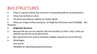
  • 16. BUS STRUCTURES • A bus is a group of lines that serves as a connecting path for several devices. • A bus may be lines or wires. • The lines carry data or address or control signal. • There are 2 types of Bus structures: 1) Single Bus Structure and 2) Multiple Bus Structure. • Single Bus Structure o Because the bus can be used for only one transfer at a time, only 2 units can actively use the bus at any given time. o Bus control lines are used to arbitrate multiple requests for use of the bus. o Advantages: Low cost & Flexibility for attaching peripheral devices.
  • 17. BUS STRUCTURES Multiple Bus Structure o Systems that contain multiple buses achieve more concurrency in operations. o Two or more transfers can be carried out at the same time. o Advantage: Better performance. o Disadvantage: Increased cost.
  • 18. Contd ….. • The devices connected to a bus vary widely in their speed of operation. • To synchronize their operational-speed, buffer-registers can be used. • Buffer Registers are included with the devices to hold the information during transfers. • Prevent a high-speed processor from being locked to a slow I/O device during data transfers. • For example consider the transfer of character from processor to printer. • The processor sends the character over bus to the printer buffer. Once the buffer is loaded, the printer starts printing without intervention by the processor. • The bus and processor are no longer needed and can be released for other activity. • Thus the buffer registers smooth out timing differences among processors, memory and I/O devices
  • 19. SOFTWARE • Software is a collection of programs. • To run application software, the system must already contain some system software in the memory. System software performs the following functions: • Receiving and interpreting user commands. • Entering and editing application programs and storing them as files in the secondary storage. • Managing the storage and storage of files in the secondary storage devices. • Running the standard application programs such as word processors, spreadsheets, or data supplied by the user. • Controlling I/O units to receive input information and produce output results. • Translating programs from source code to object code. • Linking and running user-written application programs.
  • 20. Contd ….. Application programs are usually written in high-level programming language, such as C,C++, Java etc. A system software program called a compiler translates high-level language program to a suitable machine language program. Languages Computer programming languages are divided in to three categories: 1. High-level languages 2. Assembly languages 3. Machine languages
  • 21. Contd ……. High-level languages: • Languages with the highest level of abstraction are called high-level languages. • They are said to be platform independent; means the same program code can be converted and run on computers with different microprocessors and operating systems without modification. • Examples: C++, Java, and FORTRAN. Assembly languages: • Assembly languages are at much lower level of abstraction. • Each microprocessor has its own assembly language. • A program written in the assembly language of one microprocessor cannot be run on a computer that has a different microprocessor. • Assembly languages are platform dependent.
  • 22. Contd ….. Machine languages: • Lowest levels of programming languages are machine languages. • These languages contain the binary values. • Programmers do not write programs in machine level language. • Programs written in high-level language of assembly language are converted to machine language, which is then executed by the microprocessor. • Machine languages are also platform dependent; each microprocessor has its own machine language.
  • 23. Contd …. Translators: • A program written in high-level language is called as source code. To convert the source code into machine code, translators are needed. • A translator takes a program written in source language as input and converts it into a program in target language as output. • It also detects and reports the error during translation. Roles of translator are • Translating the high-level language program input into an equivalent machine language program. • Providing diagnostic messages wherever the programmer violates specification of the high-level language program.
  • 24. Contd ….. Different type of translators The different types of translator are as follows: Compiler: Compiler is a translator which is used to convert programs in high-level language to low-level language. It translates the entire program and also reports the errors in source program encountered during the translation. Figure: Compiler
  • 25. Contd ….. Assembler Assembler is a translator which is used to translate the assembly language code into machine language code. Figure 1.6 Assembler
  • 26. Contd ….. Loader: • In computing, a loader is the part of an operating system that is responsible for loading programs and libraries. • It is one of the essential stages in the process of starting a program, as it places programs into memory and prepares them for execution. • Loading a program involves reading the contents of the executable file containing the program instructions into memory, and then carrying out other required preparatory tasks to prepare the executable for running. • Once loading is complete, the operating system starts the program by passing control to the loaded program code.
  • 27. Contd …. Linker: After compilation or assembling process, object code is generated. Linker links this object code with other required object code or library files to make it an executable file. Operating System: • OS is a large program, or actually a collection of routines , that is used to control the sharing of and interaction among various computer units. • In order to understand the basics of operating system, let us consider a system with one processor, one disk, and one printer. • First we discuss the steps involved in running the application program. Assume that the application program is stored in disk. • First step is to transfer this file in to the memory.
  • 28. Contd ….. • When the transfer is complete, execution of the program is started. • Assume that the part of the program’s task involves reading a data file from the disk in to the memory, performing some computations on the data, and printing the results. • When execution of the program reaches the point where the data file is needed, the program requests the operating system to transfer the data from the disk to memory. • The OS performs this task and passes the execution control back to the application program, which then proceed to perform the required computation. • When the computation is completed and the results are ready to be printed, the application program again sends a request to the OS. • An OS routine is then executed to cause the printer to print the results.
  • 29. Contd ….. This above process is illustrated by the time-line diagram as shown in the fig. below.
  • 30. PERFORMANCE • The most important measure of the performance of a computer is how quickly it can execute programs. The speed with which a computer executes program is affected by the design of its hardware. For best performance, it is necessary to design the compiles, the machine instruction set, and the hardware in a coordinated way. • The total time required to execute the program is elapsed time is a measure of the performance of the entire computer system. It is affected by the speed of the processor, the disk and the printer. The time needed to execute a instruction is called the processor time.
  • 31. Contd ….. • Just as the elapsed time for the execution of a program depends on all units in a computer system, the processor time depends on the hardware involved in the execution of individual machine instructions. This h a r d w a r e comprises the processor and the memory which are usually connected by the bus as shown in the below figure. Figure The Processor cache
  • 32. Contd …. • The pertinent parts of the fig. c are repeated in fig. d which includes the cache memory as part of the processor unit. • Let us examine the flow of program instructions and data between the memory and the processor. At the start of execution, all program instructions and the required data are stored in the main memory. • As the execution proceeds, instructions are fetched one by one over the bus into the processor, and a copy is placed in the cache later if the same instruction or data item is needed a second time, it is read directly from the cache. • The processor and relatively small cache memory can be fabricated on a single IC chip. The internal speed of performing the basic steps of instruction processing on chip is very high and is considerably faster than the speed at which the instruction and data can be fetched from the main memory.
  • 33. Contd ….. • A program will be executed faster if the movement of instructions and data between the main memory and the processor is minimized, which is achieved by using the cache. • For example:- Suppose a number of instructions are executed repeatedly over a short period of time as happens in a program loop. If these instructions are available in the cache, they can be fetched quickly during the period of repeated use. The same applies to the data that are used repeatedly.
  • 34. Contd …. Processor clock • Processor circuits are controlled by a timing signal called clock. The clock designer the regular time intervals called clock cycles. To execute a machine instruction the processor divides the action to be performed into a sequence of basic steps that each step can be completed in one clock cycle. The length P of one clock cycle is an important parameter that affects the processor performance. • Processor used in today’s personal computer and work station have a clock rates that range from a few hundred million to over a billion cycles per second.
  • 35. Contd …. Basic performance equation • We now focus our attention on the processor time component of the total elapsed time. Let ‘T’ be the processor time required to execute a program that has been prepared in some high-level language. • The compiler generates a machine language object program that corresponds to the source program. Assume that complete execution of the program requires the execution of N machine cycle language instructions. • The number N is the actual number of instruction execution and is not necessarily equal to the number of machine cycle instructions in the object program. Some instruction may be executed more than once, which in the case for instructions inside a program loop others may not be executed all, depending on the input data used.
  • 36. Contd ….. • Suppose that the average number of basic steps needed to execute one machine cycle instruction is S, where each basic step is completed in one clock cycle. If clock rate is ‘R’ cycles per second, the program execution time is given by T=N*S/R this is often referred to as the basic performance equation. • We must emphasize that N, S & R are not independent parameters changing one may affect another. Introducing a new feature in the design of a processor will lead to improved performance only if the overall result is to reduce the value of T.
  • 37. Contd ….. Pipelining and super scalar operation: - • We assume that instructions are executed one after the other. Hence the value of S is the total number of basic steps, or clock cycles, required to execute one instruction. A substantial improvement in performance can be achieved by overlapping the execution of successive instructions using a technique called pipelining. Consider Add R1 R2 R3 • This adds the contents of R1 & R2 and places the sum into R3. • The contents of R1 & R2 are first transferred to the inputs of ALU. After the addition operation is performed, the sum is transferred to R3. The processor can read the next instruction from the memory, while the addition operation is being performed. Then of that instruction also uses, the ALU, its operand can be transferred to the ALU inputs at the same time that the add instructions is being transferred to R3.
  • 38. Contd ….. • In the ideal case if all instructions are overlapped to the maximum degree possible the execution proceeds at the rate of one instruction completed in each clock cycle. Individual instructions still require several clock cycles to complete. • But for the purpose of computing T, effective value of S is 1. • A higher degree of concurrency can be achieved if multiple instructions pipelines are implemented in the processor. • This means that multiple functional units are used creating parallel paths through which different instructions can be executed in parallel with such an arrangement, it becomes possible to start the execution of several instructions in every clock cycle. • This mode of operation is called superscalar execution. If it can be sustained for a long time during program execution the effective value of S can be reduced to less than one. • But the parallel execution must preserve logical correctness of programs, that is the results produced must be same as those produced by the serial execution of program instructions. Now a days may processor are designed in this manner.
  • 39. Contd ….. Clock rate These are two possibilities for increasing the clock rate ‘R’. • Improving the IC technology makes logical circuit faster, which reduces the time of execution of basic steps. This allows the clock period P, to be reduced and the clock rate R to be increased. • Reducing the amount of processing done in one basic step also makes it possible to reduce the clock period P. however if the actions that have to be performed by an instructions remain the same, the number of basic steps needed may increase. • Increase in the value ‘R’ that are entirely caused by improvements in IC technology affects all aspects of the processor’s operation equally with the exception of the time it takes to access the main memory. In the presence of cache the percentage of accesses to the main memory is small. Hence much of the performance gain excepted from the use of faster technology can be realized.
  • 40. Contd …… Instruction set CISC & RISC:- • Simple instructions require a small number of basic steps to execute. Complex instructions involve a large number of steps. For a processor that has only simple instruction a large number of instructions may be needed to perform a given programming task. This could lead to a large value of ‘N’ and a small • value of ‘S’ on the other hand if individual instructions perform more complex operations, a fewer instructions will be needed, leading to a lower value of N and a larger value of S. It is not obvious if one choice is better than the other. • But complex instructions combined with pipelining (effective value of S= 1) would achieve one best performance. However, it is much easier to implement efficient pipelining in processors with simple instruction sets.
  • 41. Contd …… RISC CISC Simple instructions taking one cycle. Complex instructions taking multiple cycle. Instructions are executed by hardwired control unit. Instructions are executed by microprogrammed control unit. Few instructions. Many instructions. Fixed format instructions. Variable format instructions. Few addressing modes, and most instructions have register to register addressing mode. Many addressing modes. Multiple register set. Single register set. Highly pipelined. No pipelined or less pipelined.
  • 42. Performance measurements • It is very important to be able to access the performance of a computer, comp designers use performance estimates to evaluate the effectiveness of new features. • The previous argument suggests that the performance of a computer is given by the execution time T, for the program of interest. • Inspite of the performance equation being so simple, the evaluation of ‘T’ is highly complex. Moreover the parameters like the clock speed and various architectural features are not reliable indicators of the expected performance. • Hence measurement of computer performance using bench mark programs is done to make comparisons possible, standardized programs must be used.
  • 43. Contd….. • The performance measure is the time taken by the computer to execute a given bench mark. Initially some attempts were made to create artificial programs that could be used as bench mark programs. But synthetic programs do not properly predict the performance obtained when real application programs are run. • A non profit organization called SPEC- system performance evaluation corporation selects and publishes bench marks. • The program selected range from game playing, compiler, and data base applications to numerically intensive programs in astrophysics and quantum chemistry. In each case, the program is compiled under test, and the running time on a real computer is measured. The same program is also compiled and run on one computer selected as reference.
  • 44. Contd …… The ‘SPEC’ rating is computed as follows. SPEC rating = Running time on the reference computer Running time on the computer under test If the SPEC rating = 50 • Means that the computer under test is 50 times as fast as the ultra Sparc This is repeated for all the programs in the SPEC suit, and the geometric mean of the result is computed. • Let SPECi be the rating for program ‘i’ in the suite. The overall SPEC rating for the computer is given by Where ‘n’ = number of programs in suite. • Since actual execution time is measured the SPEC rating is a measure of the combined effect of all factors affecting performance, including the compiler, the OS, the processor, the memory of comp being tested.
  • 45. MULTIPROCESSOR & MICROPROCESSORS • Large computers that contain a number of processor units are called multiprocessor system. • These systems either execute a number of different application tasks in parallel or execute subtasks of a single large task in parallel • All processors usually have access to all memory locations in such system & hence they are called shared memory multiprocessor systems. • The high performance of these systems comes with much increased complexity and cost. • In contrast to multiprocessor systems, it is also possible to use an interconnected group of complete computers to achieve high total computational power. These computers normally have access to their own memory units when the tasks they are executing need to communicate data they do so by exchanging messages over a communication network. This properly distinguishes them from shared memory multiprocessors, leading to name message-passing multi computer.
  • 46. COMPUTER – GENERATIONS Generation in computer terminology is a change in technology a computer is/was being used. Initially, the generation term was used to distinguish between varying hardware technologies. But nowadays, generation includes both hardware and software, which together make up an entire computer system. There are totally five computer generations known till date. Each generation has been discussed in detail along with their time period and characteristics. Here approximate dates against each generations have been mentioned which are normally accepted.
  • 47. Contd …. Following are the main five generations of computers S.N. Generation & Description • First Generation The period of first generation: 1946-1959. Vacuum tube based. • Second Generation The period of second generation: 1959-1965. Transistor based. • Third Generation The period of third generation: 1965-1971. Integrated Circuit based. • Fourth Generation The period of fourth generation: 1971-1980. VLSI microprocessor based. • Fifth Generation The period of fifth generation: 1980-onwards. ULSI microprocessor based
  • 48. Contd …. First Generation: The period of first generation was 1946-1959. The computers of first generation used vacuum tubes as the basic components for memory and circuitry for CPU (Central Processing Unit). These tubes, like electric bulbs, produced a lot of heat and were prone to frequent fusing of the installations, therefore, were very expensive and could be afforded only by very large organization. In this generation mainly batch processing operating system were used. Punched cards, paper tape, and magnetic tape were used as input and output devices. The computers in this generation used machine code as programming language. • The main features of first generation are: Vacuum tube technology , Unreliable , Supported machine language only, Very costly , Generated lot of heat Slow, input and output devices ,Huge size, Need of A.C. ,Non- portable, Consumed lot of electricity • Some computers of this generation were: • ENIAC, EDVAC , UNIVAC , IBM-701 , BM-650
  • 49. Contd ….. Second Generation: The period of second generation was 1959-1965. In this generation transistors were used that were cheaper, consumed less power, more compact in size, more reliable and faster than the first generation machines made of vacuum tubes. In this generation, magnetic cores were used as primary memory and magnetic tape and magnetic disks as secondary storage devices. In this generation assembly language and high-level programming languages like FORTRAN, COBOL were used. The computers used batch processing and multiprogramming operating system. The main features of second generation are: • Use of transistors • Reliable in comparison to first generation computers • Faster than first generation computers • Still very costly • A.C. needed • Supported machine and assembly languages Some computers of this generation were: • IBM 1620 , IBM 7094 , CDC 1604 , CDC 3600 ,UNIVAC 1108
  • 50. Contd ….. Third Generation: The period of third generation was 1965-1971. The computers of third generation used integrated circuits (IC's) in place of transistors. A single IC has many transistors, resistors and capacitors along with the associated circuitry. The IC was invented by Jack Kilby. This development made computers smaller in size, reliable and efficient. In this generation remote processing, time-sharing, multi-programming operating system were used. High-level languages (FORTRAN-II TO IV, COBOL, PASCAL PL/1, BASIC, ALGOL-68 etc.) were used during this generation. The main features of third generation are: IC used ,More reliable in comparison to previous two generations ,Smaller size ,Generated less heat ,Faster ,Lesser maintenance ,Still costly ,A.C needed ,Consumed lesser electricity, Supported high-level language Some computers of this generation were: • IBM-360 series • Honeywell-6000 series • PDP(Personal Data Processor) • IBM-370/168 TDC-316
  • 51. Contd ……. Fourth Generation : The period of fourth generation was 1971-1980. The computers of fourth generation used Very Large Scale Integrated (VLSI) circuits. VLSI circuits having about 5000 transistors and other circuit elements and their associated circuits on a single chip made it possible to have microcomputers of fourth generation. Fourth generation computers became more powerful, compact, reliable, and affordable. As a result, it gave rise to personal computer(PC) revolution. In this generation time sharing, real time, networks, distributed operating system were used. All the high-level languages like C, C++, DBASE etc., were used in this generation.
  • 52. Contd ….. The main features of fourth generation are: • VLSI technology used • Very cheap • Portable and reliable • Use of PC's • Very small size • Pipeline processing • No A.C. needed • Concept of internet was introduced • Great developments in the fields of networks • Computers became easily available Some computers of this generation were: • DEC 10 STAR 1000 • PDP 11 CRAY-1(Super Computer) • CRAY-X-MP(Super Computer)
  • 53. Contd …… Fifth Generation: The period of fifth generation is 1980-till date. In the fifth generation, the VLSI technology became ULSI (Ultra Large Scale Integration) technology, resulting in the production of microprocessor chips having ten million electronic components. This generation is based on parallel processing hardware and AI (Artificial Intelligence) software. AI is an emerging branch in computer science, which interprets means and method of making computers think like human beings. All the high-level languages like C and C++, Java, .Net etc., are used in this generation.
  • 54. Contd …. AI includes: • Robotics , Neural Networks , Game Playing • Development of expert systems to make decisions in real life situations. • Natural language understanding and generation. The main features of fifth generation are: • ULSI technology • Development of true artificial intelligence • Development of Natural language processing • Advancement in Parallel Processing • Advancement in Super conductor technology • More user friendly interfaces with multimedia features • Availability of very powerful and compact computers at cheaperrates Some computer types of this generation are: • Desktop ,Laptop ,NoteBook , UltraBook ,ChromeBook
  • 55. Von Neumann architecture Von-Neumann computer architecture: Von-Neumann computer architecture design was proposed in 1945.It was later known as Von-Neumann architecture. Historically there have been 2 types of Computers: 1. Fixed Program Computers – Their function is very specific and they couldn’t be reprogrammed, e.g. Calculators. 2. Stored Program Computers – These can be programmed to carry out many different tasks, applications are stored on them, hence the name. Modern computers are based on a stored-program concept introduced by John Von Neumann. In this stored-program concept, programs and data are stored in the same memory. This novel idea meant that a computer built with this architecture would be much easier to reprogram. The basic structure is like this,
  • 56. Contd …. It is also known as ISA (Instruction set architecture) computer and is having three basic units: 1. The Central Processing Unit (CPU) 2. The Main Memory Unit 3. The Input/Output Device Let’s consider them in detail.
  • 57. Contd …. It is also known as ISA (Instruction set architecture) computer and is having three basic units: 1. The Central Processing Unit (CPU) 2. The Main Memory Unit 3. The Input/Output Device Let’s consider them in detail. 1. Central Processing Unit- The central processing unit is defined as the it is an electric circuit used for the executing the instruction of computer program. It has following major components: 1.Control Unit(CU) 2.Arithmetic and Logic Unit(ALU) 3.variety of Registers •
  • 58. Contd ………… Control Unit – A control unit (CU) handles all processor control signals. It directs all input and output flow, fetches code for instructions, and controls how data moves around the system. Arithmetic and Logic Unit (ALU) – The arithmetic logic unit is that part of the CPU that handles all the calculations the CPU may need, e.g. Addition, Subtraction, Comparisons. It performs Logical Operations, Bit Shifting Operations, and Arithmetic operations.