SlideShare a Scribd company logo
1
Digital Circuits
Introduction
Santanu Chattopadhyay
Electronics and Electrical Communication Engineering
N
P
T
E
L
The Start of the Modern Electronics Era
Bardeen, Shockley, and Brattain at Bell
Labs - Brattain and Bardeen invented
the bipolar transistor in 1947.
The first germanium bipolar transistor.
Roughly 50 years later, electronics
account for 10% (4 trillion dollars) of
the world GDP.
N
P
T
E
L
Electronics Milestones
1874 Braun invents the solid-state rectifier.
1906 DeForest invents triode vacuum tube.
1907-1927
First radio circuits developed from
diodes and triodes.
1925 Lilienfeld field-effect device patent
filed.
1947 Bardeen and Brattain at Bell
Laboratories invent bipolar transistors.
1952 Commercial bipolar transistor
production at Texas Instruments.
1956 Bardeen, Brattain, and Shockley
receive Nobel prize.
1958 Integrated circuit developed by Kilby and
Noyce
1961 First commercial IC from Fairchild
Semiconductor
1963 IEEE formed from merger or IRE and AIEE
1968 First commercial IC opamp
1970 One transistor DRAM cell invented by
Dennard at IBM.
1971 4004 Intel microprocessor introduced.
1978 First commercial 1-kilobit memory.
1974 8080 microprocessor introduced.
1984 Megabit memory chip introduced.
2000 Alferov, Kilby, and Kromer share Nobel
prize
N
P
T
E
L
Evolution of Electronic Devices
Vacuum
Tubes
Discrete
Transistors
SSI and MSI
Integrated
Circuits
VLSI
Surface-Mount
Circuits
N
P
T
E
L
Microelectronics Proliferation
• The integrated circuit was invented in 1958.
• World transistor production has more than doubled every year for the
past twenty years.
• Every year, more transistors are produced than in all previous years
combined.
• Approximately 109 transistors were produced in a recent year.
• Roughly 50 transistors for every ant in the world .
*Source: Gordon Moore’s Plenary address at the 2003 International Solid State
Circuits Conference. N
P
T
E
L
5 Commendments
• Moore’s Law : The number of transistors on a chip
doubles annually
• Rock’s Law : The cost of semiconductor tools doubles
every four years
• Machrone’s Law: The PC you want to buy will always
be $5000
• Metcalfe’s Law : A network’s value grows
proportionately to the number of its users squared
N
P
T
E
L
5 Commandments(cont.)
• Wirth’s Law : Software is slowing faster than
hardware is accelerating
• Further Reading: “5 Commandments”, IEEE
Spectrum December 2003, pp. 31-35.
N
P
T
E
L
Moore’s law
• Moore predicted that the number of transistors that can
be integrated on a die would grow exponentially with
time.
• Amazingly visionary – million transistor/chip barrier was
crossed in the 1980’s.
• 16 M transistors (Ultra Sparc III)
• 140 M transistor (HP PA-8500)
• 1.7B transistor (Intel Montecito)
N
P
T
E
L
N
P
T
E
L
N
P
T
E
L
Device Feature Size
• Feature size reductions
enabled by process
innovations.
• Smaller features lead to
more transistors per
unit area and therefore
higher density.
N
P
T
E
L
Rapid Increase in Density of Microelectronics
Memory chip density
versus time.
Microprocessor complexity
versus time.
N
P
T
E
L
Analog versus Digital Electronics
• Most observables are analog
• But the most convenient way to represent and
transmit information electronically is digital
• Analog/digital and digital/analog conversion is
essential
N
P
T
E
L
N
P
T
E
L
N
P
T
E
L
N
P
T
E
L
Digital signal representation
• By using binary numbers we can represent any quantity.
• For example a binary two (10) could represent a 2 volt signal.
• We generally have to agree on some sort of “code” and the dynamic
range of the signal in order to know the form and the minimum
number of bits.
• Possible digital representation for a pure sine wave of known
frequency.
– We must choose maximum value and “resolution” or “error,” then we can encode
the numbers.
– Suppose we want 1V accuracy of amplitude with maximum amplitude of 50V, we
could use a simple pure binary code with 6 bits of information.
N
P
T
E
L
Digital representations of logical functions
• Digital signals also offer an effective way to execute logic.
The formalism for performing logic with binary variables
is called switching algebra or Boolean algebra.
• Digital electronics combines two important properties:
– The ability to represent real functions by coding the information
in digital form.
– The ability to control a system by a process of manipulation and
evaluation of digital variables using switching algebra.
N
P
T
E
L
Digital Representations of logic functions (cont.)
• Digital signals can be transmitted, received, amplified, and
retransmitted with no degradation.
• Binary numbers are a natural method of expressing logic
variables.
• Complex logic functions are easily expressed as binary function.
• With digital representation, we can achieve arbitrary levels of
“ dynamic range,” that is, the ratio of the largest possible signal
to the smallest than can be distinguished above the background
noise.
• Digital information is easily and inexpensively stored
N
P
T
E
L
Signal Types
• Analog signals take on continuous
values - typically current or
voltage.
• Digital signals appear at discrete
levels. Usually we use binary
signals which utilize only two
levels.
• One level is referred to as logical
1 and logical 0 is assigned to the
other level.
N
P
T
E
L
Analog and Digital Signals
• Analog signals are continuous in
time and voltage or current.
(Charge can also be used as a
signal conveyor.)
• After digitization, the continuous
analog signal becomes a set of
discrete values, typically
separated by fixed time intervals.
N
P
T
E
L
Digital-to-Analog (D/A) Conversion
• For an n-bit D/A converter, the output voltage is expressed as:
• The smallest possible voltage change is known as the least
significant bit or LSB.
฀
VLSB  2n
VFS
฀
VO  (b
121
 b2 22
 ...  bn 2n
)VFS
N
P
T
E
L
DAC
TI’s 20-bit sigma delta DAC
N
P
T
E
L
Analog-to-Digital (A/D) Conversion
• Analog input voltage vx is converted to the nearest n-bit number.
• For a four bit converter, 0 -> vx input yields a 0000 -> 1111 digital output.
• Output is approximation of input due to the limited resolution of the n-bit
output. Error is expressed as:
V  vx  (b1 21
 b2 22
 ...  bn 2n
)VFS
N
P
T
E
L
Analog and Digital Signals
We seem to live in an analogue world –
things can be louder or quieter, hotter or colder, longer or shorter, on a “sliding
scale”.
If we record sound on a tape recorder, we’re putting an analogue signal onto
the tape.
Digital signals aren’t on a sliding scale – they’re either ON or OFF. (We call
these “1” and “0”.) There’s no “in between”.
N
P
T
E
L
Analog and Digital Signals
Are these analogue or digital?
Volume control on a radio
Light switch
Traffic lights
Water tap
Dimmer switch
Motor bike throttle
Music on a CD
Music on a tape
N
P
T
E
L
Analog and Digital Signals
A security floodlight
switches on when
you approach.
It has an analogue input (how much infra red it sees from you), and
produces a digital output (the floodlightis either on or off).
We could call it an “analog to digital converter”.
N
P
T
E
L
Analog and Digital Signals
•The problem with analog signals is noise – hiss on the
sound and speckly dots on the picture.
•When we send a signal over a long distance, the
signal gets weaker, so we need to boost (amplify) it.
•The problem is that we end up boosting the noise as
well.
N
P
T
E
L
Analog and Digital Signals
If we convert the signal into digital form, then send
it, it still gets weaker and noise still creeps in.
N
P
T
E
L
Analog and Digital Signals
Example: if you have a bad photocopy of a piece of text,
and you photocopy that, you’ll get a worse photocopy.
But if you read the text yourself, the “software” in your
brain can “reconstruct” the text, because you know what
the letter shapes are supposed to be even though they’re
blurred.
N
P
T
E
L
Analog and Digital Signals
Summary:
Analog signals suffer from noise, but don’t need
such complex equipment.
Digital signals need fast, clever electronics, but we
can get rid of any noise.
N
P
T
E
L
32
The CMOS Transistor
• CMOS transistor
– Basic switch in modern ICs
does not
conduct
0
conducts
1
gate
nMOS
does not
conduct
1
gate
pMOS
conducts
0
Silicon -- not quite a conductor or insulator: Semiconductor
2.3
a
N
P
T
E
L
Digital Circuits
Number System
Santanu Chattopadhyay
Electronics and Electrical Communication Engineering
N
P
T
E
L
Common Number Systems
System Base Symbols
Used by
humans?
Used in
computers?
Decimal 10 0, 1, … 9 Yes No
Binary 2 0, 1 No Yes
Octal 8 0, 1, … 7 No No
Hexa-
decimal
16 0, 1, … 9,
A, B, … F
No No
N
P
T
E
L
Quantities/Counting (1 of 3)
Decimal Binary Octal
Hexa-
decimal
0 0 0 0
1 1 1 1
2 10 2 2
3 11 3 3
4 100 4 4
5 101 5 5
6 110 6 6
7 111 7 7
N
P
T
E
L
Quantities/Counting (2 of 3)
Decimal Binary Octal
Hexa-
decimal
8 1000 10 8
9 1001 11 9
10 1010 12 A
11 1011 13 B
12 1100 14 C
13 1101 15 D
14 1110 16 E
15 1111 17 F
N
P
T
E
L
Quantities/Counting (3 of 3)
Decimal Binary Octal
Hexa-
decimal
16 10000 20 10
17 10001 21 11
18 10010 22 12
19 10011 23 13
20 10100 24 14
21 10101 25 15
22 10110 26 16
23 10111 27 17 Etc.
N
P
T
E
L
Conversion Among Bases
• The possibilities:
Hexadecimal
Decimal Octal
Binary
N
P
T
E
L
Quick Example
2510 = 110012 = 318 = 1916
Base
N
P
T
E
L
Decimal to Decimal (just for fun)
Hexadecimal
Decimal Octal
Binary
N
P
T
E
L
12510 => 5 x 100= 5
2 x 101= 20
1 x 102= 100
125
Base
Weight
N
P
T
E
L
Binary to Decimal
Hexadecimal
Decimal Octal
Binary
N
P
T
E
L
Binary to Decimal
• Technique
– Multiply each bit by 2n, where n is the “weight” of
the bit
– The weight is the position of the bit, starting from
0 on the right
– Add the results
N
P
T
E
L
Example
1010112 => 1 x 20 = 1
1 x 21 = 2
0 x 22 = 0
1 x 23 = 8
0 x 24 = 0
1 x 25 = 32
4310
Bit “0”
N
P
T
E
L
Octal to Decimal
Hexadecimal
Decimal Octal
Binary
N
P
T
E
L
Octal to Decimal
• Technique
– Multiply each digit by 8n, where n is the “weight”
of the digit
– The weight is the position of the digit, starting
from 0 on the right
– Add the results
N
P
T
E
L
Example
7248 => 4 x 80 = 4
2 x 81 = 16
7 x 82 = 448
46810
N
P
T
E
L
Hexadecimal to Decimal
Hexadecimal
Decimal Octal
Binary
N
P
T
E
L
Hexadecimal to Decimal
• Technique
– Multiply each digit by 16n, where n is the “weight”
of the digit
– The weight is the position of the digit, starting
from 0 on the right
– Add the results
N
P
T
E
L
Example
ABC16 => C x 160 = 12 x 1 = 12
B x 161 = 11 x 16 = 176
A x 162 = 10 x 256 = 2560
274810
N
P
T
E
L
Decimal to Binary
Hexadecimal
Decimal Octal
Binary
N
P
T
E
L
Decimal to Binary
• Technique
– Divide by two, keep track of the remainder
– First remainder is bit 0 (LSB, least-significant bit)
– Second remainder is bit 1
– Etc.
N
P
T
E
L
Example
12510 = ?2
2 125
62 1
2
31 0
2
15 1
2
7 1
2
3 1
2
1 1
2
0 1
12510 = 11111012
N
P
T
E
L
Octal to Binary
Hexadecimal
Decimal Octal
Binary
N
P
T
E
L
Octal to Binary
• Technique
– Convert each octal digit to a 3-bit equivalent
binary representation
N
P
T
E
L
Example
7058 = ?2
7 0 5
111 000 101
7058 = 1110001012
N
P
T
E
L
Hexadecimal to Binary
Hexadecimal
Decimal Octal
Binary
N
P
T
E
L
Hexadecimal to Binary
• Technique
– Convert each hexadecimal digit to a 4-bit
equivalent binary representation
N
P
T
E
L
Example
10AF16 = ?2
1 0 A F
0001 0000 1010 1111
10AF16 = 00010000101011112
N
P
T
E
L
Decimal to Octal
Hexadecimal
Decimal Octal
Binary
N
P
T
E
L
Decimal to Octal
• Technique
– Divide by 8
– Keep track of the remainder
N
P
T
E
L
Example
123410 = ?8
8 1234
154 2
8
19 2
8
2 3
8
0 2
123410 = 23228
N
P
T
E
L
Decimal to Hexadecimal
Hexadecimal
Decimal Octal
Binary
N
P
T
E
L
Decimal to Hexadecimal
• Technique
– Divide by 16
– Keep track of the remainder
N
P
T
E
L
Example
123410 = ?16
123410 = 4D216
16 1234
77 2
16
4 13 = D
16
0 4
N
P
T
E
L
Binary to Octal
Hexadecimal
Decimal Octal
Binary
N
P
T
E
L
Binary to Octal
• Technique
– Group bits in threes, starting on right
– Convert to octal digits
N
P
T
E
L
Example
10110101112 = ?8
1 011 010 111
1 3 2 7
10110101112 = 13278
N
P
T
E
L
Binary to Hexadecimal
Hexadecimal
Decimal Octal
Binary
N
P
T
E
L
Binary to Hexadecimal
• Technique
– Group bits in fours, starting on right
– Convert to hexadecimal digits
N
P
T
E
L
Example
10101110112 = ?16
10 1011 1011
2 B B
10101110112 = 2BB16
N
P
T
E
L
Octal to Hexadecimal
Hexadecimal
Decimal Octal
Binary
N
P
T
E
L
Octal to Hexadecimal
• Technique
– Use binary as an intermediary
N
P
T
E
L
Example
10768 = ?16
1 0 7 6
001 000 111 110
2 3 E
10768 = 23E16
N
P
T
E
L
Hexadecimal to Octal
Hexadecimal
Decimal Octal
Binary
N
P
T
E
L
Hexadecimal to Octal
• Technique
– Use binary as an intermediary
N
P
T
E
L
Example
1F0C16 = ?8
1 F 0 C
0001 1111 0000 1100
1 7 4 1 4
1F0C16 = 174148
N
P
T
E
L
Exercise – Convert ...
Decimal Binary Octal
Hexa-
decimal
33
1110101
703
1AF
N
P
T
E
L
Exercise – Convert …
Decimal Binary Octal
Hexa-
decimal
33 100001 41 21
117 1110101 165 75
451 111000011 703 1C3
431 110101111 657 1AF
Answer
N
P
T
E
L
Common Powers (1 of 2)
• Base 10 Power Preface Symbol
10-12 pico p
10-9 nano n
10-6 micro 
10-3 milli m
103 kilo k
106 mega M
109 giga G
1012 tera T
Value
.000000000001
.000000001
.000001
.001
1000
1000000
1000000000
1000000000000
N
P
T
E
L
Common Powers (2 of 2)
• Base 2 Power Preface Symbol
210 kilo k
220 mega M
230 Giga G
Value
1024
1048576
1073741824
• What is the value of “k”, “M”, and “G”?
• In computing, particularly w.r.t. memory,
the base-2 interpretation generally applies
N
P
T
E
L
Review – multiplying powers
• For common bases, add powers
26  210 = 216 = 65,536
or…
26  210 = 64  210 = 64k
ab  ac = ab+c
N
P
T
E
L
Binary Addition (1 of 2)
• Two 1-bit values
A B A + B
0 0 0
0 1 1
1 0 1
1 1 10
“two”
N
P
T
E
L
Binary Addition (2 of 2)
• Two n-bit values
– Add individual bits
– Propagate carries
– E.g., 10101 21
+ 11001 + 25
101110 46
1
1
N
P
T
E
L
Multiplication (1 of 3)
• Decimal (just for fun)
35
x 105
175
000
35
3675
N
P
T
E
L
Multiplication (2 of 3)
• Binary, two 1-bit values
A B A  B
0 0 0
0 1 0
1 0 0
1 1 1
N
P
T
E
L
Multiplication (3 of 3)
• Binary, two n-bit values
– As with decimal values
– E.g., 1110
x 1011
1110
1110
0000
1110
10011010
N
P
T
E
L
Fractions
• Decimal to decimal (just for fun)
3.14 => 4 x 10-2 = 0.04
1 x 10-1 = 0.1
3 x 100 = 3
3.14
N
P
T
E
L
Fractions
• Binary to decimal
10.1011 => 1 x 2-4 = 0.0625
1 x 2-3 = 0.125
0 x 2-2 = 0.0
1 x 2-1 = 0.5
0 x 20 = 0.0
1 x 21 = 2.0
2.6875
N
P
T
E
L
Fractions
• Decimal to binary
3.14579
.14579
x 2
0.29158
x 2
0.58316
x 2
1.16632
x 2
0.33264
x 2
0.66528
x 2
1.33056
etc.
11.001001...
N
P
T
E
L
Exercise – Convert …
Decimal Binary Octal
Hexa-
decimal
29.8 11101.110011… 35.63… 1D.CC…
5.8125 101.1101 5.64 5.D
3.109375 11.000111 3.07 3.1C
12.5078125 1100.10000010 14.404 C.82
N
P
T
E
L
Negative Numbers
1. Sign and Magnitude Representation
2. 1’s Complement Representation
3. 2’s Complement Representation
N
P
T
E
L
Goal of negative number systems
• Signed system: Simple. Just flip the sign bit
• 0 = positive
• 1 = negative
• One’s complement: Replace subtraction with addition
– Easy to derive (Just flip every bit)
• Two’s complement: Replace subtraction with addition
– Addition of one’s complement and one produces the
two’s complement.
N
P
T
E
L
Given a positive integer x, we represent -x
• 1’s complement:
 Formula: 2n -1 – x
• i.e. n=4, 24 – 1 – x = 15 – x
• In binary: (1 1 1 1) – (b3 b2 b1 b0)
• Just flip all the bits.
• 2’s complement:
 Formula: 2n –x
• i.e. n=4, 24 – x = 16 – x
• In binary: (1 0 0 0 0) – (0 b3 b2 b1 b0)
• Just flip all the bits and add 1.
N
P
T
E
L
Definitions:
4-Bit Example
N
P
T
E
L
Given n-bits, what is the range of my numbers in each
system?
• 3 bits:
– Signed: -3 , 3
– 1’s: -3 , 3
– 2’s: -4 , 3
• 6 bits
– Signed: -31, 31
– 1’s: -31, 31
– 2’s: -32, 31
• 5 bits:
– Signed: -15, 15
– 1’s: -15, 15
– 2’s: -16, 15
• Given 8 bits
– Signed: -127, 127
– 1’s: -127, 127
– 2’s: -128, 127
Formula for calculating the
range 
Signed & 1’s: -(2n-1 – 1) , (2n-1 – 1)
2’s: -2n-1 , (2n-1 – 1)
N
P
T
E
L
Theorem 1: For 1’s complement, given a positive
number ( xn-1 , xn-2 , … , x0 ), the negative number is
( ) where
Arithmetic Operations:
Derivation of 1’s Complement
Proof:
(i). 2n-1 in binary is an n bit vector (1,1, …, 1)
(ii). 2n-1-x in binary is (1,1, …,1) – (xn-1,xn-2, …, x0).
The result is
( )
N
P
T
E
L
Theorem 2: For 2’s complement, given a positive integer x, the
negative number is the sum of its 1’s complement and 1.
Proof: 2n – x = 2n – 1 – x + 1. Thus, the 2’s complement is
( ) + (0, 0, …, 1)
Ex: x = 9 (01001)
1’s -9 (10110)
31– 9 = 22
2’s -9 (10111)
32 – 9 = 23
Ex: x = 13 (01101)
1’s -13 (10010)
31-13=18
2’s -13 (10011)
32-13=19
Arithmetic Operations: Derivation of 2’s Complement
N
P
T
E
L
xn-1 xn-2 … x0
xn-1 xn-2 … x0
Inverters
One’s Complement Hardware:
N
P
T
E
L
Arithmetic Operations: 2’s Complement
Input: two positive integers x & y,
1. We represent the operands in two’s complement.
2. We sum up the two operands and ignore bit n.
3. The result is the solution in two’s complement.
Arithmetic 2’s complement
x + y x + y
x - y x + (2n - y) = 2n+(x-y)
-x + y (2n - x) + y =2n+(-x+y)
-x - y (2n - x) + (2n - y) = 2n+2n-x-y
N
P
T
E
L
Arithmetic Operations: Example: 4 – 3 = 1
0100
+ 1101
10001  1 (after discarding extra bit)
410 = 01002
310 = 00112 -310 11012
We discard the extra 1 at the left which is 2n from 2’s complement
of -3. Note that bit bn-1 is 0. Thus, the result is positive.
N
P
T
E
L
Arithmetic Operations: Example: -4 +3 = -1
1100
+ 0011
1111  Using two’s comp.  0000 + 1 = 1, so our answer is -1
410 = 01002 -410  Using two’s comp. 1011 + 1 = 11002
(Invert bits)
310 = 00112
If left-most bit is 1, it means that we have a negative
number. N
P
T
E
L
Arithmetic Operations: 1’s Complement
Input: two positive integers x & y,
1. We represent the operands in one’s complement.
2. We sum up the two operands.
3. We subtract 2n-1 if there is carry out at left.
4. The result is the solution in one’s complement.
Arithmetic 1’s complement
x + y x + y
x - y x + (2n -1- y) = 2n-1+(x-y)
-x + y (2n -1-x) + y =2n-1+(-x+y)
-x - y (2n -1-x) + (2n -1-y) = 2n-1+(2n-1-x-y)
N
P
T
E
L
Arithmetic Operations: Example: 4 – 3 = 1
0100 (4 in decimal )
+ 1100 (12 in decimal or 15-3 )
1,0000 (16 in decimal or 15+1 )
0001(after subtracting 2n-1)
410 = 01002
310 = 00112 -310 11002 in one’s complement
We discard the extra 1 at the left which is 2n and add one at the
first bit. N
P
T
E
L
Arithmetic Operations: Example: -4 +3 = -1
1011 ( 11 in decimal or 15-4 )
+ 0011 ( 3 in decimal )
1110 ( 14 in decimal or 15-1 )
410 = 01002 -410  Using one’s comp. 10112
(Invert bits)
310 = 00112
If the left-most bit is 1, it means that we have a negative
number. N
P
T
E
L

More Related Content

PPT
Digital Logic Design Lecture Notes 1.ppt
PPT
Conclusion in this titty tittle 106_1.ppt
PPTX
DIGITAL-ELECTRONICS-lesson-1 (1).jejsjjsjs
PPTX
DE UNIT1.pptx
PPTX
Lecture 1& 2.pptx
PPTX
Chapter 1.pptx
PPTX
Chapter_Three.pptx of digital component design
PPT
2013 digital sytem-1-lecture01
Digital Logic Design Lecture Notes 1.ppt
Conclusion in this titty tittle 106_1.ppt
DIGITAL-ELECTRONICS-lesson-1 (1).jejsjjsjs
DE UNIT1.pptx
Lecture 1& 2.pptx
Chapter 1.pptx
Chapter_Three.pptx of digital component design
2013 digital sytem-1-lecture01

Similar to Digital Electronics NPTEL Slides (WEEK 1) (20)

PPT
LN_1_DigitalEL.ppt... Hard work and cool
PPTX
digi.elec.number%20system.pptx
PPTX
DE and LD [Autosave gyideffgfd] (1).pptx
PPTX
Digital Logic Design Lecture 01
PPTX
Digital Electronic and it application
PPTX
digital-electronics lecture Ch 1and 2 -1.pptx
PPTX
VHDL_Lec1.pptx
DOCX
Physics investigatory project for class 12 logic gates
PDF
lecture Fatmasultak235555551626342617.pdf
PPT
Chapter1.ppt
PPT
computer logic and digital design chapter 1
PDF
Digital electronics(EC8392) unit- 1-Sesha Vidhya S/ ASP/ECE/RMKCET
PDF
Embedded Application on Microcontroller in Assembly and Embedded C
PPTX
Dgital logic by professional professor in ioe
PPT
Introduction to Digital Electronics by PPT
PPT
IntroductiontoDigitalElectronics IntroductiontoDigitalElectronics.ppt
PPT
fffggggggggggggggggggggghhhhhhhhhhhhhhhhhh.ppt
PPT
An Introduction to Computer Logic and Digital Design.ppt
PPT
Data Structure and AlgorithmChapter1.ppt
PPT
Chapter1
LN_1_DigitalEL.ppt... Hard work and cool
digi.elec.number%20system.pptx
DE and LD [Autosave gyideffgfd] (1).pptx
Digital Logic Design Lecture 01
Digital Electronic and it application
digital-electronics lecture Ch 1and 2 -1.pptx
VHDL_Lec1.pptx
Physics investigatory project for class 12 logic gates
lecture Fatmasultak235555551626342617.pdf
Chapter1.ppt
computer logic and digital design chapter 1
Digital electronics(EC8392) unit- 1-Sesha Vidhya S/ ASP/ECE/RMKCET
Embedded Application on Microcontroller in Assembly and Embedded C
Dgital logic by professional professor in ioe
Introduction to Digital Electronics by PPT
IntroductiontoDigitalElectronics IntroductiontoDigitalElectronics.ppt
fffggggggggggggggggggggghhhhhhhhhhhhhhhhhh.ppt
An Introduction to Computer Logic and Digital Design.ppt
Data Structure and AlgorithmChapter1.ppt
Chapter1
Ad

Recently uploaded (20)

PDF
Complications of Minimal Access Surgery at WLH
PPTX
Lesson notes of climatology university.
PDF
Computing-Curriculum for Schools in Ghana
PPTX
school management -TNTEU- B.Ed., Semester II Unit 1.pptx
PDF
FourierSeries-QuestionsWithAnswers(Part-A).pdf
PDF
Chapter 2 Heredity, Prenatal Development, and Birth.pdf
PPTX
Cell Types and Its function , kingdom of life
PPTX
Introduction_to_Human_Anatomy_and_Physiology_for_B.Pharm.pptx
PDF
ANTIBIOTICS.pptx.pdf………………… xxxxxxxxxxxxx
PDF
Black Hat USA 2025 - Micro ICS Summit - ICS/OT Threat Landscape
PPTX
GDM (1) (1).pptx small presentation for students
PPTX
Cell Structure & Organelles in detailed.
PDF
Classroom Observation Tools for Teachers
PDF
Microbial disease of the cardiovascular and lymphatic systems
PDF
VCE English Exam - Section C Student Revision Booklet
PDF
RMMM.pdf make it easy to upload and study
PDF
102 student loan defaulters named and shamed – Is someone you know on the list?
PDF
O5-L3 Freight Transport Ops (International) V1.pdf
PDF
Module 4: Burden of Disease Tutorial Slides S2 2025
PPTX
Renaissance Architecture: A Journey from Faith to Humanism
Complications of Minimal Access Surgery at WLH
Lesson notes of climatology university.
Computing-Curriculum for Schools in Ghana
school management -TNTEU- B.Ed., Semester II Unit 1.pptx
FourierSeries-QuestionsWithAnswers(Part-A).pdf
Chapter 2 Heredity, Prenatal Development, and Birth.pdf
Cell Types and Its function , kingdom of life
Introduction_to_Human_Anatomy_and_Physiology_for_B.Pharm.pptx
ANTIBIOTICS.pptx.pdf………………… xxxxxxxxxxxxx
Black Hat USA 2025 - Micro ICS Summit - ICS/OT Threat Landscape
GDM (1) (1).pptx small presentation for students
Cell Structure & Organelles in detailed.
Classroom Observation Tools for Teachers
Microbial disease of the cardiovascular and lymphatic systems
VCE English Exam - Section C Student Revision Booklet
RMMM.pdf make it easy to upload and study
102 student loan defaulters named and shamed – Is someone you know on the list?
O5-L3 Freight Transport Ops (International) V1.pdf
Module 4: Burden of Disease Tutorial Slides S2 2025
Renaissance Architecture: A Journey from Faith to Humanism
Ad

Digital Electronics NPTEL Slides (WEEK 1)

  • 1. 1 Digital Circuits Introduction Santanu Chattopadhyay Electronics and Electrical Communication Engineering N P T E L
  • 2. The Start of the Modern Electronics Era Bardeen, Shockley, and Brattain at Bell Labs - Brattain and Bardeen invented the bipolar transistor in 1947. The first germanium bipolar transistor. Roughly 50 years later, electronics account for 10% (4 trillion dollars) of the world GDP. N P T E L
  • 3. Electronics Milestones 1874 Braun invents the solid-state rectifier. 1906 DeForest invents triode vacuum tube. 1907-1927 First radio circuits developed from diodes and triodes. 1925 Lilienfeld field-effect device patent filed. 1947 Bardeen and Brattain at Bell Laboratories invent bipolar transistors. 1952 Commercial bipolar transistor production at Texas Instruments. 1956 Bardeen, Brattain, and Shockley receive Nobel prize. 1958 Integrated circuit developed by Kilby and Noyce 1961 First commercial IC from Fairchild Semiconductor 1963 IEEE formed from merger or IRE and AIEE 1968 First commercial IC opamp 1970 One transistor DRAM cell invented by Dennard at IBM. 1971 4004 Intel microprocessor introduced. 1978 First commercial 1-kilobit memory. 1974 8080 microprocessor introduced. 1984 Megabit memory chip introduced. 2000 Alferov, Kilby, and Kromer share Nobel prize N P T E L
  • 4. Evolution of Electronic Devices Vacuum Tubes Discrete Transistors SSI and MSI Integrated Circuits VLSI Surface-Mount Circuits N P T E L
  • 5. Microelectronics Proliferation • The integrated circuit was invented in 1958. • World transistor production has more than doubled every year for the past twenty years. • Every year, more transistors are produced than in all previous years combined. • Approximately 109 transistors were produced in a recent year. • Roughly 50 transistors for every ant in the world . *Source: Gordon Moore’s Plenary address at the 2003 International Solid State Circuits Conference. N P T E L
  • 6. 5 Commendments • Moore’s Law : The number of transistors on a chip doubles annually • Rock’s Law : The cost of semiconductor tools doubles every four years • Machrone’s Law: The PC you want to buy will always be $5000 • Metcalfe’s Law : A network’s value grows proportionately to the number of its users squared N P T E L
  • 7. 5 Commandments(cont.) • Wirth’s Law : Software is slowing faster than hardware is accelerating • Further Reading: “5 Commandments”, IEEE Spectrum December 2003, pp. 31-35. N P T E L
  • 8. Moore’s law • Moore predicted that the number of transistors that can be integrated on a die would grow exponentially with time. • Amazingly visionary – million transistor/chip barrier was crossed in the 1980’s. • 16 M transistors (Ultra Sparc III) • 140 M transistor (HP PA-8500) • 1.7B transistor (Intel Montecito) N P T E L
  • 11. Device Feature Size • Feature size reductions enabled by process innovations. • Smaller features lead to more transistors per unit area and therefore higher density. N P T E L
  • 12. Rapid Increase in Density of Microelectronics Memory chip density versus time. Microprocessor complexity versus time. N P T E L
  • 13. Analog versus Digital Electronics • Most observables are analog • But the most convenient way to represent and transmit information electronically is digital • Analog/digital and digital/analog conversion is essential N P T E L
  • 17. Digital signal representation • By using binary numbers we can represent any quantity. • For example a binary two (10) could represent a 2 volt signal. • We generally have to agree on some sort of “code” and the dynamic range of the signal in order to know the form and the minimum number of bits. • Possible digital representation for a pure sine wave of known frequency. – We must choose maximum value and “resolution” or “error,” then we can encode the numbers. – Suppose we want 1V accuracy of amplitude with maximum amplitude of 50V, we could use a simple pure binary code with 6 bits of information. N P T E L
  • 18. Digital representations of logical functions • Digital signals also offer an effective way to execute logic. The formalism for performing logic with binary variables is called switching algebra or Boolean algebra. • Digital electronics combines two important properties: – The ability to represent real functions by coding the information in digital form. – The ability to control a system by a process of manipulation and evaluation of digital variables using switching algebra. N P T E L
  • 19. Digital Representations of logic functions (cont.) • Digital signals can be transmitted, received, amplified, and retransmitted with no degradation. • Binary numbers are a natural method of expressing logic variables. • Complex logic functions are easily expressed as binary function. • With digital representation, we can achieve arbitrary levels of “ dynamic range,” that is, the ratio of the largest possible signal to the smallest than can be distinguished above the background noise. • Digital information is easily and inexpensively stored N P T E L
  • 20. Signal Types • Analog signals take on continuous values - typically current or voltage. • Digital signals appear at discrete levels. Usually we use binary signals which utilize only two levels. • One level is referred to as logical 1 and logical 0 is assigned to the other level. N P T E L
  • 21. Analog and Digital Signals • Analog signals are continuous in time and voltage or current. (Charge can also be used as a signal conveyor.) • After digitization, the continuous analog signal becomes a set of discrete values, typically separated by fixed time intervals. N P T E L
  • 22. Digital-to-Analog (D/A) Conversion • For an n-bit D/A converter, the output voltage is expressed as: • The smallest possible voltage change is known as the least significant bit or LSB. ฀ VLSB  2n VFS ฀ VO  (b 121  b2 22  ...  bn 2n )VFS N P T E L
  • 23. DAC TI’s 20-bit sigma delta DAC N P T E L
  • 24. Analog-to-Digital (A/D) Conversion • Analog input voltage vx is converted to the nearest n-bit number. • For a four bit converter, 0 -> vx input yields a 0000 -> 1111 digital output. • Output is approximation of input due to the limited resolution of the n-bit output. Error is expressed as: V  vx  (b1 21  b2 22  ...  bn 2n )VFS N P T E L
  • 25. Analog and Digital Signals We seem to live in an analogue world – things can be louder or quieter, hotter or colder, longer or shorter, on a “sliding scale”. If we record sound on a tape recorder, we’re putting an analogue signal onto the tape. Digital signals aren’t on a sliding scale – they’re either ON or OFF. (We call these “1” and “0”.) There’s no “in between”. N P T E L
  • 26. Analog and Digital Signals Are these analogue or digital? Volume control on a radio Light switch Traffic lights Water tap Dimmer switch Motor bike throttle Music on a CD Music on a tape N P T E L
  • 27. Analog and Digital Signals A security floodlight switches on when you approach. It has an analogue input (how much infra red it sees from you), and produces a digital output (the floodlightis either on or off). We could call it an “analog to digital converter”. N P T E L
  • 28. Analog and Digital Signals •The problem with analog signals is noise – hiss on the sound and speckly dots on the picture. •When we send a signal over a long distance, the signal gets weaker, so we need to boost (amplify) it. •The problem is that we end up boosting the noise as well. N P T E L
  • 29. Analog and Digital Signals If we convert the signal into digital form, then send it, it still gets weaker and noise still creeps in. N P T E L
  • 30. Analog and Digital Signals Example: if you have a bad photocopy of a piece of text, and you photocopy that, you’ll get a worse photocopy. But if you read the text yourself, the “software” in your brain can “reconstruct” the text, because you know what the letter shapes are supposed to be even though they’re blurred. N P T E L
  • 31. Analog and Digital Signals Summary: Analog signals suffer from noise, but don’t need such complex equipment. Digital signals need fast, clever electronics, but we can get rid of any noise. N P T E L
  • 32. 32 The CMOS Transistor • CMOS transistor – Basic switch in modern ICs does not conduct 0 conducts 1 gate nMOS does not conduct 1 gate pMOS conducts 0 Silicon -- not quite a conductor or insulator: Semiconductor 2.3 a N P T E L
  • 33. Digital Circuits Number System Santanu Chattopadhyay Electronics and Electrical Communication Engineering N P T E L
  • 34. Common Number Systems System Base Symbols Used by humans? Used in computers? Decimal 10 0, 1, … 9 Yes No Binary 2 0, 1 No Yes Octal 8 0, 1, … 7 No No Hexa- decimal 16 0, 1, … 9, A, B, … F No No N P T E L
  • 35. Quantities/Counting (1 of 3) Decimal Binary Octal Hexa- decimal 0 0 0 0 1 1 1 1 2 10 2 2 3 11 3 3 4 100 4 4 5 101 5 5 6 110 6 6 7 111 7 7 N P T E L
  • 36. Quantities/Counting (2 of 3) Decimal Binary Octal Hexa- decimal 8 1000 10 8 9 1001 11 9 10 1010 12 A 11 1011 13 B 12 1100 14 C 13 1101 15 D 14 1110 16 E 15 1111 17 F N P T E L
  • 37. Quantities/Counting (3 of 3) Decimal Binary Octal Hexa- decimal 16 10000 20 10 17 10001 21 11 18 10010 22 12 19 10011 23 13 20 10100 24 14 21 10101 25 15 22 10110 26 16 23 10111 27 17 Etc. N P T E L
  • 38. Conversion Among Bases • The possibilities: Hexadecimal Decimal Octal Binary N P T E L
  • 39. Quick Example 2510 = 110012 = 318 = 1916 Base N P T E L
  • 40. Decimal to Decimal (just for fun) Hexadecimal Decimal Octal Binary N P T E L
  • 41. 12510 => 5 x 100= 5 2 x 101= 20 1 x 102= 100 125 Base Weight N P T E L
  • 42. Binary to Decimal Hexadecimal Decimal Octal Binary N P T E L
  • 43. Binary to Decimal • Technique – Multiply each bit by 2n, where n is the “weight” of the bit – The weight is the position of the bit, starting from 0 on the right – Add the results N P T E L
  • 44. Example 1010112 => 1 x 20 = 1 1 x 21 = 2 0 x 22 = 0 1 x 23 = 8 0 x 24 = 0 1 x 25 = 32 4310 Bit “0” N P T E L
  • 45. Octal to Decimal Hexadecimal Decimal Octal Binary N P T E L
  • 46. Octal to Decimal • Technique – Multiply each digit by 8n, where n is the “weight” of the digit – The weight is the position of the digit, starting from 0 on the right – Add the results N P T E L
  • 47. Example 7248 => 4 x 80 = 4 2 x 81 = 16 7 x 82 = 448 46810 N P T E L
  • 49. Hexadecimal to Decimal • Technique – Multiply each digit by 16n, where n is the “weight” of the digit – The weight is the position of the digit, starting from 0 on the right – Add the results N P T E L
  • 50. Example ABC16 => C x 160 = 12 x 1 = 12 B x 161 = 11 x 16 = 176 A x 162 = 10 x 256 = 2560 274810 N P T E L
  • 51. Decimal to Binary Hexadecimal Decimal Octal Binary N P T E L
  • 52. Decimal to Binary • Technique – Divide by two, keep track of the remainder – First remainder is bit 0 (LSB, least-significant bit) – Second remainder is bit 1 – Etc. N P T E L
  • 53. Example 12510 = ?2 2 125 62 1 2 31 0 2 15 1 2 7 1 2 3 1 2 1 1 2 0 1 12510 = 11111012 N P T E L
  • 54. Octal to Binary Hexadecimal Decimal Octal Binary N P T E L
  • 55. Octal to Binary • Technique – Convert each octal digit to a 3-bit equivalent binary representation N P T E L
  • 56. Example 7058 = ?2 7 0 5 111 000 101 7058 = 1110001012 N P T E L
  • 58. Hexadecimal to Binary • Technique – Convert each hexadecimal digit to a 4-bit equivalent binary representation N P T E L
  • 59. Example 10AF16 = ?2 1 0 A F 0001 0000 1010 1111 10AF16 = 00010000101011112 N P T E L
  • 60. Decimal to Octal Hexadecimal Decimal Octal Binary N P T E L
  • 61. Decimal to Octal • Technique – Divide by 8 – Keep track of the remainder N P T E L
  • 62. Example 123410 = ?8 8 1234 154 2 8 19 2 8 2 3 8 0 2 123410 = 23228 N P T E L
  • 64. Decimal to Hexadecimal • Technique – Divide by 16 – Keep track of the remainder N P T E L
  • 65. Example 123410 = ?16 123410 = 4D216 16 1234 77 2 16 4 13 = D 16 0 4 N P T E L
  • 66. Binary to Octal Hexadecimal Decimal Octal Binary N P T E L
  • 67. Binary to Octal • Technique – Group bits in threes, starting on right – Convert to octal digits N P T E L
  • 68. Example 10110101112 = ?8 1 011 010 111 1 3 2 7 10110101112 = 13278 N P T E L
  • 70. Binary to Hexadecimal • Technique – Group bits in fours, starting on right – Convert to hexadecimal digits N P T E L
  • 71. Example 10101110112 = ?16 10 1011 1011 2 B B 10101110112 = 2BB16 N P T E L
  • 73. Octal to Hexadecimal • Technique – Use binary as an intermediary N P T E L
  • 74. Example 10768 = ?16 1 0 7 6 001 000 111 110 2 3 E 10768 = 23E16 N P T E L
  • 76. Hexadecimal to Octal • Technique – Use binary as an intermediary N P T E L
  • 77. Example 1F0C16 = ?8 1 F 0 C 0001 1111 0000 1100 1 7 4 1 4 1F0C16 = 174148 N P T E L
  • 78. Exercise – Convert ... Decimal Binary Octal Hexa- decimal 33 1110101 703 1AF N P T E L
  • 79. Exercise – Convert … Decimal Binary Octal Hexa- decimal 33 100001 41 21 117 1110101 165 75 451 111000011 703 1C3 431 110101111 657 1AF Answer N P T E L
  • 80. Common Powers (1 of 2) • Base 10 Power Preface Symbol 10-12 pico p 10-9 nano n 10-6 micro  10-3 milli m 103 kilo k 106 mega M 109 giga G 1012 tera T Value .000000000001 .000000001 .000001 .001 1000 1000000 1000000000 1000000000000 N P T E L
  • 81. Common Powers (2 of 2) • Base 2 Power Preface Symbol 210 kilo k 220 mega M 230 Giga G Value 1024 1048576 1073741824 • What is the value of “k”, “M”, and “G”? • In computing, particularly w.r.t. memory, the base-2 interpretation generally applies N P T E L
  • 82. Review – multiplying powers • For common bases, add powers 26  210 = 216 = 65,536 or… 26  210 = 64  210 = 64k ab  ac = ab+c N P T E L
  • 83. Binary Addition (1 of 2) • Two 1-bit values A B A + B 0 0 0 0 1 1 1 0 1 1 1 10 “two” N P T E L
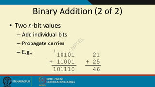
  • 84. Binary Addition (2 of 2) • Two n-bit values – Add individual bits – Propagate carries – E.g., 10101 21 + 11001 + 25 101110 46 1 1 N P T E L
  • 85. Multiplication (1 of 3) • Decimal (just for fun) 35 x 105 175 000 35 3675 N P T E L
  • 86. Multiplication (2 of 3) • Binary, two 1-bit values A B A  B 0 0 0 0 1 0 1 0 0 1 1 1 N P T E L
  • 87. Multiplication (3 of 3) • Binary, two n-bit values – As with decimal values – E.g., 1110 x 1011 1110 1110 0000 1110 10011010 N P T E L
  • 88. Fractions • Decimal to decimal (just for fun) 3.14 => 4 x 10-2 = 0.04 1 x 10-1 = 0.1 3 x 100 = 3 3.14 N P T E L
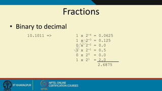
  • 89. Fractions • Binary to decimal 10.1011 => 1 x 2-4 = 0.0625 1 x 2-3 = 0.125 0 x 2-2 = 0.0 1 x 2-1 = 0.5 0 x 20 = 0.0 1 x 21 = 2.0 2.6875 N P T E L
  • 90. Fractions • Decimal to binary 3.14579 .14579 x 2 0.29158 x 2 0.58316 x 2 1.16632 x 2 0.33264 x 2 0.66528 x 2 1.33056 etc. 11.001001... N P T E L
  • 91. Exercise – Convert … Decimal Binary Octal Hexa- decimal 29.8 11101.110011… 35.63… 1D.CC… 5.8125 101.1101 5.64 5.D 3.109375 11.000111 3.07 3.1C 12.5078125 1100.10000010 14.404 C.82 N P T E L
  • 92. Negative Numbers 1. Sign and Magnitude Representation 2. 1’s Complement Representation 3. 2’s Complement Representation N P T E L
  • 93. Goal of negative number systems • Signed system: Simple. Just flip the sign bit • 0 = positive • 1 = negative • One’s complement: Replace subtraction with addition – Easy to derive (Just flip every bit) • Two’s complement: Replace subtraction with addition – Addition of one’s complement and one produces the two’s complement. N P T E L
  • 94. Given a positive integer x, we represent -x • 1’s complement:  Formula: 2n -1 – x • i.e. n=4, 24 – 1 – x = 15 – x • In binary: (1 1 1 1) – (b3 b2 b1 b0) • Just flip all the bits. • 2’s complement:  Formula: 2n –x • i.e. n=4, 24 – x = 16 – x • In binary: (1 0 0 0 0) – (0 b3 b2 b1 b0) • Just flip all the bits and add 1. N P T E L
  • 96. Given n-bits, what is the range of my numbers in each system? • 3 bits: – Signed: -3 , 3 – 1’s: -3 , 3 – 2’s: -4 , 3 • 6 bits – Signed: -31, 31 – 1’s: -31, 31 – 2’s: -32, 31 • 5 bits: – Signed: -15, 15 – 1’s: -15, 15 – 2’s: -16, 15 • Given 8 bits – Signed: -127, 127 – 1’s: -127, 127 – 2’s: -128, 127 Formula for calculating the range  Signed & 1’s: -(2n-1 – 1) , (2n-1 – 1) 2’s: -2n-1 , (2n-1 – 1) N P T E L
  • 97. Theorem 1: For 1’s complement, given a positive number ( xn-1 , xn-2 , … , x0 ), the negative number is ( ) where Arithmetic Operations: Derivation of 1’s Complement Proof: (i). 2n-1 in binary is an n bit vector (1,1, …, 1) (ii). 2n-1-x in binary is (1,1, …,1) – (xn-1,xn-2, …, x0). The result is ( ) N P T E L
  • 98. Theorem 2: For 2’s complement, given a positive integer x, the negative number is the sum of its 1’s complement and 1. Proof: 2n – x = 2n – 1 – x + 1. Thus, the 2’s complement is ( ) + (0, 0, …, 1) Ex: x = 9 (01001) 1’s -9 (10110) 31– 9 = 22 2’s -9 (10111) 32 – 9 = 23 Ex: x = 13 (01101) 1’s -13 (10010) 31-13=18 2’s -13 (10011) 32-13=19 Arithmetic Operations: Derivation of 2’s Complement N P T E L
  • 99. xn-1 xn-2 … x0 xn-1 xn-2 … x0 Inverters One’s Complement Hardware: N P T E L
  • 100. Arithmetic Operations: 2’s Complement Input: two positive integers x & y, 1. We represent the operands in two’s complement. 2. We sum up the two operands and ignore bit n. 3. The result is the solution in two’s complement. Arithmetic 2’s complement x + y x + y x - y x + (2n - y) = 2n+(x-y) -x + y (2n - x) + y =2n+(-x+y) -x - y (2n - x) + (2n - y) = 2n+2n-x-y N P T E L
  • 101. Arithmetic Operations: Example: 4 – 3 = 1 0100 + 1101 10001  1 (after discarding extra bit) 410 = 01002 310 = 00112 -310 11012 We discard the extra 1 at the left which is 2n from 2’s complement of -3. Note that bit bn-1 is 0. Thus, the result is positive. N P T E L
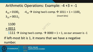
  • 102. Arithmetic Operations: Example: -4 +3 = -1 1100 + 0011 1111  Using two’s comp.  0000 + 1 = 1, so our answer is -1 410 = 01002 -410  Using two’s comp. 1011 + 1 = 11002 (Invert bits) 310 = 00112 If left-most bit is 1, it means that we have a negative number. N P T E L
  • 103. Arithmetic Operations: 1’s Complement Input: two positive integers x & y, 1. We represent the operands in one’s complement. 2. We sum up the two operands. 3. We subtract 2n-1 if there is carry out at left. 4. The result is the solution in one’s complement. Arithmetic 1’s complement x + y x + y x - y x + (2n -1- y) = 2n-1+(x-y) -x + y (2n -1-x) + y =2n-1+(-x+y) -x - y (2n -1-x) + (2n -1-y) = 2n-1+(2n-1-x-y) N P T E L
  • 104. Arithmetic Operations: Example: 4 – 3 = 1 0100 (4 in decimal ) + 1100 (12 in decimal or 15-3 ) 1,0000 (16 in decimal or 15+1 ) 0001(after subtracting 2n-1) 410 = 01002 310 = 00112 -310 11002 in one’s complement We discard the extra 1 at the left which is 2n and add one at the first bit. N P T E L
  • 105. Arithmetic Operations: Example: -4 +3 = -1 1011 ( 11 in decimal or 15-4 ) + 0011 ( 3 in decimal ) 1110 ( 14 in decimal or 15-1 ) 410 = 01002 -410  Using one’s comp. 10112 (Invert bits) 310 = 00112 If the left-most bit is 1, it means that we have a negative number. N P T E L