discrete time signals and systems
Download as PPTX, PDF5 likes1,232 views

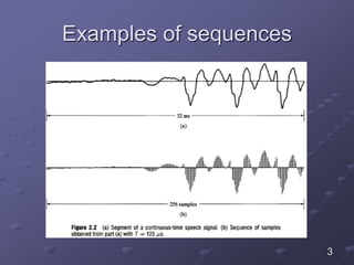
This document discusses discrete-time signals and sequences. It defines discrete-time signals as sequences of numbers represented as x[n], where n is an integer. In practice, sequences arise from periodically sampling an analog signal. Linear time-invariant (LTI) systems are described by the convolution sum, where the impulse response h[n] completely characterizes the system. FIR systems have impulse responses of finite duration, while IIR systems can have impulse responses that extend to infinity.
![Discrete-Time signals:
sequences
Discreet-Time signals are represented
mathematically as sequences of numbers
The sequence is denoted 𝑥[𝑛], and it is
written formally as
𝑥 = 𝑥 𝑛 ; −∞ < 𝑛 < ∞
where n is an integer number
In practice sequences arises from the
periodic sampling of an analog signal
1](https://image.slidesharecdn.com/639discrete-timesignalsandsystems-150402120935-conversion-gate01/85/discrete-time-signals-and-systems-1-320.jpg)
![Discrete-Time signals:
sequences
In this case the numeric value of the nth
number in the sequence is equal to the
value of the analog signal, 𝑥 𝑎(𝑡), at time
𝑛𝑇
𝑥 𝑛 = 𝑥 𝑎[𝑛𝑇]
2](https://image.slidesharecdn.com/639discrete-timesignalsandsystems-150402120935-conversion-gate01/85/discrete-time-signals-and-systems-2-320.jpg)
![Basic sequences and sequence
operation
The product and sum of two sequences x[n]
and 𝑦[𝑛] are defined as the sample by
sample product and sum
Multiplication of a sequence 𝑥[𝑛] by a
number 𝛼 is defined as the multiplication of
each sample value by 𝛼
A sample 𝑦[𝑛] is said to be delayed or shifted
version of 𝑥[𝑛] if 𝑦 𝑛 = 𝑥[ 𝑛 −
4](https://image.slidesharecdn.com/639discrete-timesignalsandsystems-150402120935-conversion-gate01/85/discrete-time-signals-and-systems-4-320.jpg)


![Special sequences Unit sample
sequence
In general any sequence can be written as
𝑥 𝑛 = 𝑘=−∞
∞
𝑥 𝑘 𝛿[𝑛 − 𝑘]
7](https://image.slidesharecdn.com/639discrete-timesignalsandsystems-150402120935-conversion-gate01/85/discrete-time-signals-and-systems-7-320.jpg)


![Special sequences Unit step
sequence
The unit step sequence in terms of
delayed impulses can be written as 𝑢 𝑛 =
𝛿 𝑛 + 𝛿 𝑛 − 1 + 𝛿 𝑛 − 2 + ⋯ =
𝑘=0
∞
𝛿 𝑛 − 𝑘
Note that the impulse sequence can be
expressed as the first backward difference
of the unit step sequence
𝛿 𝑛 = 𝑢 𝑛 − 𝑢[𝑛 − 1]
10](https://image.slidesharecdn.com/639discrete-timesignalsandsystems-150402120935-conversion-gate01/85/discrete-time-signals-and-systems-10-320.jpg)


![Periodic sequence
A periodic sequence is a sequence that
satisfies the following equation
𝑥 𝑛 = 𝑥[𝑛 + 𝑁],
Where 𝑁 is an integer number
If this condition is tested for the discrete
time sinusoids, then
Which requires
16](https://image.slidesharecdn.com/639discrete-timesignalsandsystems-150402120935-conversion-gate01/85/discrete-time-signals-and-systems-16-320.jpg)


![Discrete time system examples
There are many systems will be
investigated through out this course
Examples of these systems are
1. The ideal delay system which is described
mathematically by 𝑦 𝑛 = 𝑥 𝑛 − 𝑛 𝑑 , −∞ <
𝑛 < ∞
2. Moving average system which is described
mathematically by
1
𝑀1+𝑀2+1 𝑘=−𝑀1
𝑀2
𝑥[𝑛 − 𝑘]
21](https://image.slidesharecdn.com/639discrete-timesignalsandsystems-150402120935-conversion-gate01/85/discrete-time-signals-and-systems-21-320.jpg)
![Discrete time system
classifications
Systems can be classifieds into one of the
following categories
1. Memoryless Systems. A system is classified
into memoryless system if the output 𝑦 𝑛 at
every value of 𝑛 depends only on the input
of 𝑥[𝑛] at the same value of 𝑛. An example
of a memoryless system is the squarer
system described by 𝑦 𝑛 = 𝑥[𝑛] 2
22](https://image.slidesharecdn.com/639discrete-timesignalsandsystems-150402120935-conversion-gate01/85/discrete-time-signals-and-systems-22-320.jpg)
![Discrete time system
classifications
2. Linear systems. Any system satisfies the
superposition and the scaling property is
classifieds as a linear system. As an
example of a linear system is the
accumulator system described by
𝑦 𝑛 = 𝑘=−∞
𝑛
𝑥[𝑘]
3. Time-invariant system is a system for which
a time shift or delay of the input sequence
causes a corresponding shift in the output
sequence
23](https://image.slidesharecdn.com/639discrete-timesignalsandsystems-150402120935-conversion-gate01/85/discrete-time-signals-and-systems-23-320.jpg)
![Discrete time system
classifications
Example show that the accumulator system
𝑦 𝑛 = 𝑘=−∞
𝑛
𝑥[𝑘] is a time invariant system
solution
Assume that the input to the accumulator is
𝑥1 𝑛 = 𝑥[𝑛 − 𝑛0], then its output is 𝑦1 𝑛 =
𝑘=−∞
𝑛
𝑥1[𝑘] = 𝑘=−∞
𝑛
𝑥[𝑘 − 𝑛0]
Let 𝑘1 = 𝑘 − 𝑛0
This means that
𝑦1 𝑛 = 𝑘=−∞
𝑛−𝑛0
𝑥[𝑘1] = y[n − 𝑛0]
24](https://image.slidesharecdn.com/639discrete-timesignalsandsystems-150402120935-conversion-gate01/85/discrete-time-signals-and-systems-24-320.jpg)
![Discrete time system
classifications
4. Causality, a system is causal if the output
sequence value at the index 𝑛 − 𝑛0 depends
only on the input sequence values for 𝑛 ≤ 𝑛0
For example the forward difference system
described by 𝑦 𝑛 = 𝑥 𝑛 + 1 − 𝑥 𝑛 is not causal
because the current value of the output depends on
future value of the input
Another example is the backward difference system
𝑦 𝑛 = 𝑥 𝑛 − 𝑥[𝑛 − 1] is a causal system since the
output depends only on the present and past
values of the input
25](https://image.slidesharecdn.com/639discrete-timesignalsandsystems-150402120935-conversion-gate01/85/discrete-time-signals-and-systems-25-320.jpg)
![Discrete time system
classifications
5. Stability, a system is stable if and only if
every bounded input sequence produces a
bounded output sequence
Such a system is called BIBO
in equation form
𝑥 𝑛 ≤ 𝐵𝑥 < ∞ → 𝑦 𝑛 ≤ 𝐵𝑦 < ∞
In general any sequence that has the form
𝑦 𝑛 = 𝑘=−∞
𝑛
𝑥[𝑘] < ∞ is stable system
26](https://image.slidesharecdn.com/639discrete-timesignalsandsystems-150402120935-conversion-gate01/85/discrete-time-signals-and-systems-26-320.jpg)
![Linear time-invariant system
The linear time-invariant system is an
important system since many of the system
we deal with in signal processing are of this
type
The output sequence in response to the
input sequence applied to the input of the
linear time-invariant system is given by the
convolutional sum 𝑦 𝑛 =
𝑘=−∞
∞
𝑥 𝑘 ℎ[𝑛 − 𝑘]
27](https://image.slidesharecdn.com/639discrete-timesignalsandsystems-150402120935-conversion-gate01/85/discrete-time-signals-and-systems-27-320.jpg)
![Linear time-invariant system
In order to compute the convolution we
draw both ℎ 𝑛 − 𝑘 and 𝑥[𝑘] sequences as
shown below
28](https://image.slidesharecdn.com/639discrete-timesignalsandsystems-150402120935-conversion-gate01/85/discrete-time-signals-and-systems-28-320.jpg)


![2.4 Properties of linear time
invariant system
The output sequence 𝑦[𝑛] of all LTI are
described by the convolution sum
𝑦 𝑛 =
𝑘=−∞
∞
𝑥 𝑘 ℎ[𝑛 − 𝑘]
Where ℎ[𝑛] is the impulse response of the LTI
system
This means that ℎ[𝑛] is a complete
characterization of the properties of a specific
LTI system
36](https://image.slidesharecdn.com/639discrete-timesignalsandsystems-150402120935-conversion-gate01/85/discrete-time-signals-and-systems-36-320.jpg)

![Graphical representation of
combined LTI systems
38
Cascaded systems can be presented
by a single system whose impulse
response is given by ℎ 𝑛 = ℎ1[𝑛] ∗
ℎ2[𝑛]. Cascaded systems satisfy the
convolution commutative property
Systems connected in parallel
can be replaced by a single
system whose ℎ 𝑛 = ℎ1 𝑛 +
ℎ2[𝑛].](https://image.slidesharecdn.com/639discrete-timesignalsandsystems-150402120935-conversion-gate01/85/discrete-time-signals-and-systems-38-320.jpg)
![Stability and causality in terms
of ℎ[𝑛]
LTI are stable if and only if there impulse
response is absolutely summable i.e.
𝑆 =
𝑘=−∞
∞
ℎ[𝑘] < ∞
LTI is causal if ℎ 𝑛 = 0 𝑓𝑜𝑟 𝑛 < 0
Causality means that the difference
equations describing the system can be
solved recursively
39](https://image.slidesharecdn.com/639discrete-timesignalsandsystems-150402120935-conversion-gate01/85/discrete-time-signals-and-systems-39-320.jpg)
![FIR systems – reflected in the
h[n]
Ideal delay
𝑦 𝑛 = 𝑥 𝑛 − 𝑛 𝑑 , −∞ < 𝑛 < ∞
ℎ 𝑛 = 𝛿 𝑛 − 𝑛 𝑑 , 𝑛 𝑑 𝑝𝑜𝑠𝑖𝑡𝑖𝑣𝑒 𝑖𝑛𝑡𝑒𝑔𝑒𝑟
Forward difference
𝑦 𝑛 = 𝑥 𝑛 + 1 − 𝑥 𝑛
ℎ 𝑛 = 𝛿 𝑛 + 1 − 𝛿 𝑛
Backward difference
𝑦 𝑛 = 𝑥 𝑛 − 𝑥 𝑛 − 1
ℎ 𝑛 = 𝛿 𝑛 − 𝛿[𝑛 − 1]
Finite-duration impulse response (FIR) system are
characterized by an impulse response has that has only a
finite number of nonzero samples
40](https://image.slidesharecdn.com/639discrete-timesignalsandsystems-150402120935-conversion-gate01/85/discrete-time-signals-and-systems-40-320.jpg)
![IIR systems – reflected in the
ℎ[𝑛]
Accumulator
𝑦 𝑛 =
𝑘=−∞
𝑛
𝑥[𝑘]
ℎ 𝑛 =
𝑘=−∞
𝑛
𝛿[𝑘] = 𝑢[𝑛]
Infinite duration impulse response (IIR) system has ℎ[𝑛]
whose duration extends to infinity
Stability S = 𝑘=−∞
∞
ℎ[𝑘] <?
∞
FIR systems always are stable, if each value of ℎ[𝑛] values is
finite in magnitude
IIR systems can be stable, e.g. ℎ 𝑛 = 𝑎 𝑛 𝑢 𝑛 , 𝑎 < 1 →
𝑛=0
∞
𝑎 𝑛
=
1
1− 𝑎
< ∞
41](https://image.slidesharecdn.com/639discrete-timesignalsandsystems-150402120935-conversion-gate01/85/discrete-time-signals-and-systems-41-320.jpg)


![Example of difference equations
Now the output sequence can be written as
Or alternatively it can be written as
If we compare the last equation with 𝑘=0
𝑁
𝑎 𝑘[𝑛 − 𝑘] =
𝑘=0
𝑀
𝑏 𝑚[𝑚 − 𝑘] we find that 𝑁 = 1, 𝑎0 = 1, 𝑎1 =
− 1, 𝑀 = 0, 𝑏0 = 1
46](https://image.slidesharecdn.com/639discrete-timesignalsandsystems-150402120935-conversion-gate01/85/discrete-time-signals-and-systems-46-320.jpg)

![Solving the Linear constant
coefficient difference equations
Difference equations are similar to differential
equations in continuous systems
The solution for the difference equations is
composed from the homogeneous and
particular solutions as described
mathematically by
𝑦 𝑛 = 𝑦𝑝 𝑛 + 𝑦ℎ[𝑛]
48](https://image.slidesharecdn.com/639discrete-timesignalsandsystems-150402120935-conversion-gate01/85/discrete-time-signals-and-systems-48-320.jpg)
![Solving the Linear constant
coefficient difference equations
The homogeneous solution 𝑦ℎ 𝑛 is obtained
with 𝑥 𝑛 = 0
This means that the difference equation reduces
to
𝑘=0
𝑁
𝑎 𝑘 𝑦ℎ[𝑛 − 𝑘] = 0
Since 𝑦ℎ 𝑛 has 𝑁 undetermined coefficients, a
set of 𝑁 auxiliary conditions is required for the
unique specification of 𝑦[𝑛] for a given 𝑥 𝑛
49](https://image.slidesharecdn.com/639discrete-timesignalsandsystems-150402120935-conversion-gate01/85/discrete-time-signals-and-systems-49-320.jpg)
![Solving the Linear constant
coefficient difference equations
These auxiliary conditions might consist of
specifying fixed values of 𝑦[𝑛] at specific values
of 𝑛, such as 𝑦[−1], 𝑦[−2], … , 𝑦[−𝑁]
The above step results in a set of 𝑁 linear
equations for the 𝑁 undetermined coefficients,
which can be solved to produce the required
coefficients
50](https://image.slidesharecdn.com/639discrete-timesignalsandsystems-150402120935-conversion-gate01/85/discrete-time-signals-and-systems-50-320.jpg)
![Recursive solution of the
difference equations
The output samples for 𝑛 ≥ 0 can be computed
recursively by rearranging the difference
equation as shown below
𝑦 𝑛 = −
𝑘=1
𝑁
𝑎 𝑘
𝑎0
𝑦 𝑛 − 𝑘 +
𝑘=0
𝑀
𝑏 𝑘
𝑎0
𝑥[𝑛 − 𝑘]
If the input 𝑥[𝑛], together with a set of auxiliary
values 𝑦 −1 , 𝑦 −2 , … , 𝑦[−𝑁] is specified then
the output 𝑦[0] can be computed
51](https://image.slidesharecdn.com/639discrete-timesignalsandsystems-150402120935-conversion-gate01/85/discrete-time-signals-and-systems-51-320.jpg)
![Recursive solution of the
difference equations
With 𝑦 0 , 𝑦 −1 , … , 𝑦[−𝑁 + 1] available 𝑦[1] can
be computed
To generate values of 𝑦[𝑛] for 𝑛 < −𝑁, we can
rearrange the linear constant coefficient
difference equation as shown below
𝑦 𝑛 − 𝑁 = −
𝑘=0
𝑁−1
𝑎 𝑘
𝑎 𝑁
𝑦 𝑛 − 𝑘 +
𝑘=0
𝑀
𝑏 𝑘
𝑎 𝑁
𝑥[𝑛 − 𝑘]
52](https://image.slidesharecdn.com/639discrete-timesignalsandsystems-150402120935-conversion-gate01/85/discrete-time-signals-and-systems-52-320.jpg)


![Recursive computation example
If we use the auxiliary conditions 𝑦[−1] = 𝑐, we
can compute 𝑦[𝑛] for 𝑛 < −1 as follows
• 𝑦 −2 = 𝑎−1
𝑦 −1 − 𝑥 −1 = 𝑎−1
𝑐
• 𝑦 −3 = 𝑎−1
𝑦 −2 − 𝑥 −2 = 𝑎−1
𝑎−1
𝑐 = 𝑎−2
𝑐
• 𝑦 −4 = 𝑎−1
𝑦 −3 − 𝑥 −3 = 𝑎−1
𝑎−2
𝑐 = 𝑎−3
𝑐
𝑦 𝑛 = 𝑎 𝑛+1
𝑐 𝑓𝑜𝑟 𝑛 ≤ −1
By combining the solutions for 𝑛 > −1 and 𝑛 ≤
− 1, we got the following solution
𝑦 𝑛 = 𝑎 𝑛+1 𝑐
56](https://image.slidesharecdn.com/639discrete-timesignalsandsystems-150402120935-conversion-gate01/85/discrete-time-signals-and-systems-56-320.jpg)
![2.6 Frequency-domain representation
of discrete time signals and systems
The frequency response of a given system
with impulse response of ℎ[𝑛] is defined
by
𝐻 𝑒 𝑗𝜔
=
𝑘=−∞
∞
ℎ 𝑘 𝑒−𝑗𝜔𝑘
The output of any system characterized by
its frequency response is given by
𝑦 𝑛 = 𝐻 𝑒 𝑗𝜔
𝑒 𝑗𝜔𝑛
57](https://image.slidesharecdn.com/639discrete-timesignalsandsystems-150402120935-conversion-gate01/85/discrete-time-signals-and-systems-57-320.jpg)


![Example
Determine if 𝑥 𝑛 = 𝑎 𝑛 𝑢[𝑛] has a Fourier
transform or not. If the Fourier transform exist,
find the value of 𝑋 𝑒 𝑗𝜔
Solution
The summation
𝑛=−∞
∞
𝑥[𝑛] =
𝑛=0
∞
𝑎 𝑛
=
1
1 − 𝑎
< ∞
If and only if 𝑎 < 1 this means that the discrete
Fourier transform exists only for 𝑎 < 1
63](https://image.slidesharecdn.com/639discrete-timesignalsandsystems-150402120935-conversion-gate01/85/discrete-time-signals-and-systems-63-320.jpg)

discrete time signals and systems
- 1. Discrete-Time signals: sequences Discreet-Time signals are represented mathematically as sequences of numbers The sequence is denoted 𝑥[𝑛], and it is written formally as 𝑥 = 𝑥 𝑛 ; −∞ < 𝑛 < ∞ where n is an integer number In practice sequences arises from the periodic sampling of an analog signal 1
- 2. Discrete-Time signals: sequences In this case the numeric value of the nth number in the sequence is equal to the value of the analog signal, 𝑥 𝑎(𝑡), at time 𝑛𝑇 𝑥 𝑛 = 𝑥 𝑎[𝑛𝑇] 2
- 4. Basic sequences and sequence operation The product and sum of two sequences x[n] and 𝑦[𝑛] are defined as the sample by sample product and sum Multiplication of a sequence 𝑥[𝑛] by a number 𝛼 is defined as the multiplication of each sample value by 𝛼 A sample 𝑦[𝑛] is said to be delayed or shifted version of 𝑥[𝑛] if 𝑦 𝑛 = 𝑥[ 𝑛 − 4
- 5. MATLAB exercise Record a voice signal using the audiorecorder function for 5 seconds with the following specifications sampling frequency of 44100 Number of quantization bits 16 Number of channels = 1 for mono Try to multiply the recorded samples by a scaling factor of 𝛼 = 0.1 then by 𝛼 = 2 Play the signal and hear the voice 5
- 6. Special sequences Unit sample sequence Unit sample sequence is defined as the sequence One of the important aspects of the impulse sequence is that an arbitrary sequence can be presented as a sum of scaled, delayed impulses as shown in the next slide 6
- 7. Special sequences Unit sample sequence In general any sequence can be written as 𝑥 𝑛 = 𝑘=−∞ ∞ 𝑥 𝑘 𝛿[𝑛 − 𝑘] 7
- 8. Special sequences Unit step sequence The unit step sequence is given by 8
- 9. Special sequences Unit step sequence The unit step sequence is given by 9
- 10. Special sequences Unit step sequence The unit step sequence in terms of delayed impulses can be written as 𝑢 𝑛 = 𝛿 𝑛 + 𝛿 𝑛 − 1 + 𝛿 𝑛 − 2 + ⋯ = 𝑘=0 ∞ 𝛿 𝑛 − 𝑘 Note that the impulse sequence can be expressed as the first backward difference of the unit step sequence 𝛿 𝑛 = 𝑢 𝑛 − 𝑢[𝑛 − 1] 10
- 11. Special sequences exponential sequences Exponential sequence are important in representing and analyzing linear time invariant systems The general form of an exponential sequence is given by 𝑥 𝑛 = 𝐴𝛼 𝑛 If 𝐴 and 𝛼 are real then the sequence is real If 0 < 𝛼 < 1 and 𝐴 is positive then the sequence values are positive and decreasing with increasing 𝑛 11
- 12. Special sequences exponential sequences Graphical representation of exponential sequence 12
- 13. Special sequences sinusoidal sequences The general form of sinusoidal sequence is given by 𝑥 𝑛 = 𝐴𝑐𝑜𝑠(𝜔0 𝑛 + ∅) as shown 13
- 14. Special sequences sinusoidal and complex exponential sequence The exponential sequence 𝑥 𝑛 = 𝐴𝛼 𝑛 with complex 𝛼 has a real and imaginary parts that are exponentially weighted sinusoids If 𝛼 = 𝛼 𝑒 𝑗𝜔0 and 𝐴 = 𝐴 𝑒 𝑗∅ then the sequence can be expressed in either one of the following forms 14
- 15. Notes about sequences When discussing either complex exponential signals of the form 𝑥 𝑛 = 𝐴𝑒 𝑗𝜔0 𝑛 or real sinusoidal signal of the form 𝑥 𝑛 = 𝐴𝑐𝑜𝑠 𝜔0 𝑛 + ∅ we need only to consider frequencies in an interval of length of 2𝜋 only because 15
- 16. Periodic sequence A periodic sequence is a sequence that satisfies the following equation 𝑥 𝑛 = 𝑥[𝑛 + 𝑁], Where 𝑁 is an integer number If this condition is tested for the discrete time sinusoids, then Which requires 16
- 17. Periodic sequence Where 𝑘 is an integer A similar statement holds for the complex exponential Where 𝑁 is an integer number Again 17
- 18. Example Determine if the following sequences are periodic or not. If the sequence is periodic find its period a) 𝑥1 𝑛 = cos 𝑛𝜋 4 b) 𝑥2 𝑛 = cos 3𝑛𝜋 4 18
- 19. solution a) For the first sequence we have 𝜔0 𝑁 = 2𝜋k or 𝜋 4 𝑁 = 2𝜋𝑘 → 𝑁 = 8𝑘 since 𝑁 is an integer value the sequence is periodic b) For the second sequence 𝜔0 𝑁 = 2𝜋𝑘 or 3𝜋 4 𝑁 = 2𝜋𝑘 → 𝑁 = 8 3 𝑘 since 𝑁 is not an integer value for 𝑘 = 1 the sequence is aperiodic if 𝑁 = 8 19
- 20. 2.2 Discrete time systems A discrete-time system is a system that maps an input sequence with an output sequence 𝑦 𝑛 = 𝑇{𝑥 𝑛 } 20
- 21. Discrete time system examples There are many systems will be investigated through out this course Examples of these systems are 1. The ideal delay system which is described mathematically by 𝑦 𝑛 = 𝑥 𝑛 − 𝑛 𝑑 , −∞ < 𝑛 < ∞ 2. Moving average system which is described mathematically by 1 𝑀1+𝑀2+1 𝑘=−𝑀1 𝑀2 𝑥[𝑛 − 𝑘] 21
- 22. Discrete time system classifications Systems can be classifieds into one of the following categories 1. Memoryless Systems. A system is classified into memoryless system if the output 𝑦 𝑛 at every value of 𝑛 depends only on the input of 𝑥[𝑛] at the same value of 𝑛. An example of a memoryless system is the squarer system described by 𝑦 𝑛 = 𝑥[𝑛] 2 22
- 23. Discrete time system classifications 2. Linear systems. Any system satisfies the superposition and the scaling property is classifieds as a linear system. As an example of a linear system is the accumulator system described by 𝑦 𝑛 = 𝑘=−∞ 𝑛 𝑥[𝑘] 3. Time-invariant system is a system for which a time shift or delay of the input sequence causes a corresponding shift in the output sequence 23
- 24. Discrete time system classifications Example show that the accumulator system 𝑦 𝑛 = 𝑘=−∞ 𝑛 𝑥[𝑘] is a time invariant system solution Assume that the input to the accumulator is 𝑥1 𝑛 = 𝑥[𝑛 − 𝑛0], then its output is 𝑦1 𝑛 = 𝑘=−∞ 𝑛 𝑥1[𝑘] = 𝑘=−∞ 𝑛 𝑥[𝑘 − 𝑛0] Let 𝑘1 = 𝑘 − 𝑛0 This means that 𝑦1 𝑛 = 𝑘=−∞ 𝑛−𝑛0 𝑥[𝑘1] = y[n − 𝑛0] 24
- 25. Discrete time system classifications 4. Causality, a system is causal if the output sequence value at the index 𝑛 − 𝑛0 depends only on the input sequence values for 𝑛 ≤ 𝑛0 For example the forward difference system described by 𝑦 𝑛 = 𝑥 𝑛 + 1 − 𝑥 𝑛 is not causal because the current value of the output depends on future value of the input Another example is the backward difference system 𝑦 𝑛 = 𝑥 𝑛 − 𝑥[𝑛 − 1] is a causal system since the output depends only on the present and past values of the input 25
- 26. Discrete time system classifications 5. Stability, a system is stable if and only if every bounded input sequence produces a bounded output sequence Such a system is called BIBO in equation form 𝑥 𝑛 ≤ 𝐵𝑥 < ∞ → 𝑦 𝑛 ≤ 𝐵𝑦 < ∞ In general any sequence that has the form 𝑦 𝑛 = 𝑘=−∞ 𝑛 𝑥[𝑘] < ∞ is stable system 26
- 27. Linear time-invariant system The linear time-invariant system is an important system since many of the system we deal with in signal processing are of this type The output sequence in response to the input sequence applied to the input of the linear time-invariant system is given by the convolutional sum 𝑦 𝑛 = 𝑘=−∞ ∞ 𝑥 𝑘 ℎ[𝑛 − 𝑘] 27
- 28. Linear time-invariant system In order to compute the convolution we draw both ℎ 𝑛 − 𝑘 and 𝑥[𝑘] sequences as shown below 28
- 29. Linear time-invariant system From the Figure, we have 𝑦 𝑛 = 0 𝑓𝑜𝑟 𝑛 < 0 The next sequence interval is shown by the next graph that is 0 ≤ 𝑛 ≤ 𝑁 − 1 29
- 30. Linear time-invariant system The output sequence for this interval is given by This equation can be solved analytically by using the geometric series expansion 𝑘=𝑁1 𝑁2 𝑎 𝑘 = 𝑎 𝑁1 − 𝑎 𝑁2 +1 1 − 𝑎 30
- 31. Linear time-invariant system The output sequence for this interval is given by This equation can be solved analytically by using the geometric series expansion 𝑘=𝑁1 𝑁2 𝑎 𝑘 = 𝑎 𝑁1 − 𝑎 𝑁2 +1 1 − 𝑎 31
- 32. Convolution example Which yields the following result 𝑦 𝑛 = 𝑘=0 𝑛 𝑎 𝑘 = 1 − 𝑎 𝑛+1 1 − 𝑎 𝑓𝑜𝑟 0 ≤ 𝑛 ≤ 𝑁 − 1 We consider the next interval when 0 < 𝑛 − 𝑁 + 1 The output sequence is given by 32
- 33. Convolution example Which yields the following result The final answer for the output sequence for these three intervals is given by 33
- 35. Convolution in Matlab Convolution can be accomplished easily in matlab by using the function conv(u,v) The above example can be solved easily in matalb by using the following code in matlab n=1:10; h=ones(1,5); x=0.4.^n; Y=conv(x,h); stem(y); 35
- 36. 2.4 Properties of linear time invariant system The output sequence 𝑦[𝑛] of all LTI are described by the convolution sum 𝑦 𝑛 = 𝑘=−∞ ∞ 𝑥 𝑘 ℎ[𝑛 − 𝑘] Where ℎ[𝑛] is the impulse response of the LTI system This means that ℎ[𝑛] is a complete characterization of the properties of a specific LTI system 36
- 37. Properties of the convolution sum commutative 𝑥 𝑛 ∗ 𝑦 𝑛 = 𝑦 𝑛 ∗ 𝑥 𝑛 Distribution over addition 𝑥 𝑛 ∗ ℎ1 𝑛 + ℎ2 𝑛 = 𝑥 𝑛 ∗ ℎ1 𝑛 + 𝑥 𝑛 ∗ ℎ2 𝑛 Associative 𝑦 𝑛 = 𝑥 𝑛 ∗ ℎ1 𝑛 ∗ ℎ2 𝑛 = 𝑥 𝑛 ∗ ℎ1 𝑛 ∗ ℎ2 𝑛 37
- 38. Graphical representation of combined LTI systems 38 Cascaded systems can be presented by a single system whose impulse response is given by ℎ 𝑛 = ℎ1[𝑛] ∗ ℎ2[𝑛]. Cascaded systems satisfy the convolution commutative property Systems connected in parallel can be replaced by a single system whose ℎ 𝑛 = ℎ1 𝑛 + ℎ2[𝑛].
- 39. Stability and causality in terms of ℎ[𝑛] LTI are stable if and only if there impulse response is absolutely summable i.e. 𝑆 = 𝑘=−∞ ∞ ℎ[𝑘] < ∞ LTI is causal if ℎ 𝑛 = 0 𝑓𝑜𝑟 𝑛 < 0 Causality means that the difference equations describing the system can be solved recursively 39
- 40. FIR systems – reflected in the h[n] Ideal delay 𝑦 𝑛 = 𝑥 𝑛 − 𝑛 𝑑 , −∞ < 𝑛 < ∞ ℎ 𝑛 = 𝛿 𝑛 − 𝑛 𝑑 , 𝑛 𝑑 𝑝𝑜𝑠𝑖𝑡𝑖𝑣𝑒 𝑖𝑛𝑡𝑒𝑔𝑒𝑟 Forward difference 𝑦 𝑛 = 𝑥 𝑛 + 1 − 𝑥 𝑛 ℎ 𝑛 = 𝛿 𝑛 + 1 − 𝛿 𝑛 Backward difference 𝑦 𝑛 = 𝑥 𝑛 − 𝑥 𝑛 − 1 ℎ 𝑛 = 𝛿 𝑛 − 𝛿[𝑛 − 1] Finite-duration impulse response (FIR) system are characterized by an impulse response has that has only a finite number of nonzero samples 40
- 41. IIR systems – reflected in the ℎ[𝑛] Accumulator 𝑦 𝑛 = 𝑘=−∞ 𝑛 𝑥[𝑘] ℎ 𝑛 = 𝑘=−∞ 𝑛 𝛿[𝑘] = 𝑢[𝑛] Infinite duration impulse response (IIR) system has ℎ[𝑛] whose duration extends to infinity Stability S = 𝑘=−∞ ∞ ℎ[𝑘] <? ∞ FIR systems always are stable, if each value of ℎ[𝑛] values is finite in magnitude IIR systems can be stable, e.g. ℎ 𝑛 = 𝑎 𝑛 𝑢 𝑛 , 𝑎 < 1 → 𝑛=0 ∞ 𝑎 𝑛 = 1 1− 𝑎 < ∞ 41
- 42. Cascading system examples Determine if the following system is causal or not Solution Since the impulse response of the cascaded system satisfy ℎ 𝑛 = 0 𝑓𝑜𝑟 𝑛 < 0 the resulting cascaded system is stable Any FIR system can be made causal by cascading it with a sufficiently long delay 42
- 43. Cascading system examples Determine the impulse response of the following cascaded systems An inverse system is given by 43
- 44. Linear constant-coefficient difference equations The Nth order linear constant coefficient equations are a subclass of linear time invariant systems The general form of these equations is 44
- 45. Example of difference equations Write the accumulator system in terms of difference equations Solution The accumulator equation is given by The output for 𝑛 − 1 can be written as 45
- 46. Example of difference equations Now the output sequence can be written as Or alternatively it can be written as If we compare the last equation with 𝑘=0 𝑁 𝑎 𝑘[𝑛 − 𝑘] = 𝑘=0 𝑀 𝑏 𝑚[𝑚 − 𝑘] we find that 𝑁 = 1, 𝑎0 = 1, 𝑎1 = − 1, 𝑀 = 0, 𝑏0 = 1 46
- 47. Example of difference equations The difference equations gives a better understanding of how we can be implement the accumulator system in this example 47
- 48. Solving the Linear constant coefficient difference equations Difference equations are similar to differential equations in continuous systems The solution for the difference equations is composed from the homogeneous and particular solutions as described mathematically by 𝑦 𝑛 = 𝑦𝑝 𝑛 + 𝑦ℎ[𝑛] 48
- 49. Solving the Linear constant coefficient difference equations The homogeneous solution 𝑦ℎ 𝑛 is obtained with 𝑥 𝑛 = 0 This means that the difference equation reduces to 𝑘=0 𝑁 𝑎 𝑘 𝑦ℎ[𝑛 − 𝑘] = 0 Since 𝑦ℎ 𝑛 has 𝑁 undetermined coefficients, a set of 𝑁 auxiliary conditions is required for the unique specification of 𝑦[𝑛] for a given 𝑥 𝑛 49
- 50. Solving the Linear constant coefficient difference equations These auxiliary conditions might consist of specifying fixed values of 𝑦[𝑛] at specific values of 𝑛, such as 𝑦[−1], 𝑦[−2], … , 𝑦[−𝑁] The above step results in a set of 𝑁 linear equations for the 𝑁 undetermined coefficients, which can be solved to produce the required coefficients 50
- 51. Recursive solution of the difference equations The output samples for 𝑛 ≥ 0 can be computed recursively by rearranging the difference equation as shown below 𝑦 𝑛 = − 𝑘=1 𝑁 𝑎 𝑘 𝑎0 𝑦 𝑛 − 𝑘 + 𝑘=0 𝑀 𝑏 𝑘 𝑎0 𝑥[𝑛 − 𝑘] If the input 𝑥[𝑛], together with a set of auxiliary values 𝑦 −1 , 𝑦 −2 , … , 𝑦[−𝑁] is specified then the output 𝑦[0] can be computed 51
- 52. Recursive solution of the difference equations With 𝑦 0 , 𝑦 −1 , … , 𝑦[−𝑁 + 1] available 𝑦[1] can be computed To generate values of 𝑦[𝑛] for 𝑛 < −𝑁, we can rearrange the linear constant coefficient difference equation as shown below 𝑦 𝑛 − 𝑁 = − 𝑘=0 𝑁−1 𝑎 𝑘 𝑎 𝑁 𝑦 𝑛 − 𝑘 + 𝑘=0 𝑀 𝑏 𝑘 𝑎 𝑁 𝑥[𝑛 − 𝑘] 52
- 53. Recursive computation example Example: solve the following difference equation recursively 𝑦 𝑛 = 𝑎𝑦 𝑛 − 1 + 𝑥 𝑛 Assume that the input is 𝑥 𝑛 = 𝐾𝛿 𝑛 and 𝑦 −1 = 𝑐 53
- 54. Recursive computation example When 𝑛 > −1, we can use recursive computation as follows Let 𝑛 = 0 then 𝑦 0 = 𝑎𝑦 0 − 1 + 𝑥 0 𝑦 0 = 𝑎𝑦 −1 + 𝐾𝛿 0 Since 𝑦 −1 = 𝑐, then 𝑦 0 = 𝑎𝑐 + 𝐾 54
- 55. Recursive computation example Next we do the same procedure when 𝑛 = 1 • 𝑦 1 = 𝑎𝑦 1 − 1 + 𝑥 1 • 𝑦 1 = 𝑎𝑦 0 + 0 = 𝑎 𝑎𝑐 + 𝐾 = 𝑎2 𝑐 + 𝑎𝐾 • 𝑦 2 = 𝑎𝑦 1 + 0 = 𝑎 𝑎2𝑐 + 𝑎𝐾 = 𝑎3 𝑐 + 𝑎2 𝐾 • 𝑦 3 = 𝑎𝑦 2 + 0 = 𝑎 𝑎3 𝑐 + 𝑎2 𝐾 = 𝑎4 𝑐 + 𝑎3 𝐾 • 𝑦 𝑛 = 𝑎 𝑛+1 𝑐 + 𝑎 𝑛 𝐾 To determine the output for 𝑛 < 0, we express the difference equations in the form 𝑦 𝑛 − 1 = 𝑎−1 (𝑦 𝑛 − 𝑥 𝑛 ) 𝑦 𝑛 = 𝑎−1 (𝑦 𝑛 + 1 − 𝑥 𝑛 + 1 ) 55
- 56. Recursive computation example If we use the auxiliary conditions 𝑦[−1] = 𝑐, we can compute 𝑦[𝑛] for 𝑛 < −1 as follows • 𝑦 −2 = 𝑎−1 𝑦 −1 − 𝑥 −1 = 𝑎−1 𝑐 • 𝑦 −3 = 𝑎−1 𝑦 −2 − 𝑥 −2 = 𝑎−1 𝑎−1 𝑐 = 𝑎−2 𝑐 • 𝑦 −4 = 𝑎−1 𝑦 −3 − 𝑥 −3 = 𝑎−1 𝑎−2 𝑐 = 𝑎−3 𝑐 𝑦 𝑛 = 𝑎 𝑛+1 𝑐 𝑓𝑜𝑟 𝑛 ≤ −1 By combining the solutions for 𝑛 > −1 and 𝑛 ≤ − 1, we got the following solution 𝑦 𝑛 = 𝑎 𝑛+1 𝑐 56
- 57. 2.6 Frequency-domain representation of discrete time signals and systems The frequency response of a given system with impulse response of ℎ[𝑛] is defined by 𝐻 𝑒 𝑗𝜔 = 𝑘=−∞ ∞ ℎ 𝑘 𝑒−𝑗𝜔𝑘 The output of any system characterized by its frequency response is given by 𝑦 𝑛 = 𝐻 𝑒 𝑗𝜔 𝑒 𝑗𝜔𝑛 57
- 58. Frequency response of the ideal delay system Example determine the frequency response of an ideal delay system described by the following equation 𝑦 𝑛 = 𝑥 𝑛 − 𝑛 𝑑 Solution To find the frequency response we first find the impulse response of the system which can be found by substituting 𝑥 𝑛 = 𝛿 𝑛 58
- 59. Frequency response of the ideal delay system This means that 𝐻 𝑛 = 𝛿 𝑛 − 𝑛 𝑑 Now the frequency response is given by 𝐻 𝑒 𝑗𝜔 = 𝑛=−∞ ∞ 𝛿 𝑛 − 𝑛 𝑑 𝑒−𝑗𝜔𝑛 = 𝑒−𝑗𝜔𝑛 𝑑 𝐻 𝑒 𝑗𝜔 can be written in rectangular form as illustrated below 𝐻 𝑒 𝑗𝜔 = 𝐻 𝑅 𝑒 𝑗𝜔 + 𝐻𝐼 𝑒 𝑗𝜔 𝐻 𝑅 𝑒 𝑗𝜔 = cos(𝜔𝑛 𝑑) , 𝐻𝐼 𝑒 𝑗𝜔 = − sin 𝜔𝑛 𝑑 from Euler identity 59
- 60. 2.7 Representation of sequences by Fourier transforms In order to represent a given sequence by its Fourier transform we can use the following equation 𝑋 𝑒 𝑗𝜔 𝑛=−∞ ∞ 𝑥 𝑛 𝑒−𝑗𝜔𝑛 However the inverse Fourier transform is given by 𝑥 𝑛 = 1 2𝜋 −𝜋 𝜋 𝑋 𝑒 𝑗𝜔 𝑒 𝑗𝜔𝑛 𝑑𝜔 60
- 61. Representation of sequences by Fourier transforms For the discrete time signals, the value of 𝜔 is restricted to an interval of 2𝜋 The low frequency component of discrete time signals are located around 𝜔 = 0 The high frequency component are located around 𝜔 = ±𝜋 61
- 62. Convergence of the Fourier transform In general not all the signals have Fourier transform Only the absolutely summable signals have their Fourier transform exits Absolutely summable signals are signals satisfying the following condition 𝑛=−∞ ∞ 𝑥 𝑛 62
- 63. Example Determine if 𝑥 𝑛 = 𝑎 𝑛 𝑢[𝑛] has a Fourier transform or not. If the Fourier transform exist, find the value of 𝑋 𝑒 𝑗𝜔 Solution The summation 𝑛=−∞ ∞ 𝑥[𝑛] = 𝑛=0 ∞ 𝑎 𝑛 = 1 1 − 𝑎 < ∞ If and only if 𝑎 < 1 this means that the discrete Fourier transform exists only for 𝑎 < 1 63
- 64. Example The summation 𝑋 𝑒 𝑗𝜔 = 𝑛=0 ∞ 𝑎 𝑛 𝑒−𝑗𝜔𝑛 = 𝑛=0 ∞ (𝑎𝑒−𝑗𝜔 ) 𝑛 = 1 1 − 𝑎𝑒−𝑗𝜔 If and only if 𝑎 < 1 this means that the discrete Fourier transform exists only for 𝑎 < 1 64