SlideShare a Scribd company logo
Presented By
G.S.Bandi
What is a Governing System
To govern means to control and regulate
certain parameters to achieve expected
results.
Turbine Governing system is meant for
regulation of turbine speed under no
load and varying load condition.
It helps in precise control of grid frequency
under normal operation and protects the
machine as well as grid during emergency
situation.
Gov System of KWU M/C
•KWU machines are equipped with Hydraulic
and Electro-hydraulic governing system .
•Under normal operating condition EH
governing system is used
•Hydraulic governing system is used as backup
governing system on failure of EH governing.
Electro
Hydraulic
converter
Mechanical
Hydraulic
converter
EL
HYD
HYD
HYD
M
I
N
Hydraulic
Actuation System
for Control v/v
positioning
Structure of KWU
Gov System
Electro hydraulic governing
(EHC)
Electro hydraulic controller is an integral part of
EAST(Electronic Automation for turbine)
supplied with KWU turbines.
The EHC has a task to control the steam flow to
the turbine by positioning of HP & IP control
valves and
•control speed during start up
•control load of TG after synchronization
ADVANTAGES OF EHC
• i) Increases the life of turboset by conservative
operation with the aid of TSE
• ii)High operational reliability and safety with
integrated circuits , as well as speed and load
measurement in multiple channels
• iii) Precise maintenance of the rated frequency of the
power grid by means of an exact frequency load curve.
• iv) Low speed deviation under all operational
conditions.
• v) Support of the pressure control system
Elements of EHC
• EHC can be divided into following sub-sections:
• 1 Speed measurement and Speed controller
• 2 Load measurement and Load controller
• 3 Pressure controller
• 4 Selection circuit(Control mode selection)
• 5 Admission /Position Controller
Speed
Control loop
Load
Control loop
Pressure
Control loop
Selection
Circuit
Admission
control loop
EL
HYD
Structure of EHC
Speed Controller
• Is used to increase turbine speed from barring speed
to rated speed in a controlled manner .
• To assist Auto synchronizer in synchronizing the
machine and taking the block load.
• After synchronization speed controller can be used
for taking load up to 100% but as a normal practice
approx. after 10% of load ,load controller is taken
into service. It is done because during speed
controller mode a small frequency change will cause
corresponding opening in valve ( hence in load)
Speed controller can be divided into sub sections
Speed set point,
Speed set point control, Dn/Dt monitoring,
Speed control Loop, No load correction.
• a) Speed set point can be changed from cabinet, desk,
auto Synchronizer and SGC turbine. The set point is
called nR. The set point changes at a gradient of
2160 rpm/min up to a setting 2820 rpm. After
2820rpm speed set point changes at a gradient of
360 rpm/min which enables accurate setting of set
point in the working range .
1a Speed measurement
• Hall probes are mounted around a disc (fitted
at the turbine shaft) containing 120 magnets
(60 N-pole & 60-S pole alternatively) . An
advantage of the same is that one rotation of
disc will generate 60 positive pulses & So, by
counting the pulses for one second we can
directly determine the turbo set speed in rpm.
b) Speed Set Point control
• Speed Set Point control :- The set point
fixed in the earlier section cannot be passed
to speed control loop directly as it is only
the desired value which can be changed at a
very fast rate and it does not take care of
turbine stress margin. Speed set point
control circuit decides the acceleration of
the turbine depending on TSE margins.
c) Dn/Dt Monitoring
This section detects low acceleration of turbine and
brings back the turbine speed to a safe speed of 600
rpm. Dn/ Dt acts when following conditions are
fulfilled
• A hrnc is more than 0.0 V
• B All E S V’s open.
• C Generator circuit breaker in open condition.
• D Actual speed (n a c t) < 2850 rpm.
• E Speed set point (nR) > 2850 rpm
• F Dn/Dt < 108 rpm/min
d)Speed Controller Loop
• Speed Controller loop is PD (P) loop .
• A deviation of 150 rpm will correspond to full
opening of the control valve (with the
assumption that full opening of control valve
will give full load at rated parameters)
• If error + 150 rpm then hRnc will be 10v
• if error is -150 rpm then hRnc will be -10v
• if error is zero speed controller o/p will be
zero
e)No load Correction
• As the speed controller loop is PD (P) so an error in
the input is a must to keep the valves open for
running the at the rated speed .To Provide this error
between set point and actual value a pressure
dependent correction signal is given , as the valve
opening required for running the machine at rated
speed is directly dependent on steam pressure.
Hence, for correction purpose practical reading
should be taken when the machine is running at
rated speed at different pressure
For example :- Turbine running at 3000 rpm
Output of speed controller at (50Kg/Cm2)=1.5V
Output of speed controller at (150Kg/Cm2)=0.8V
The pressure transmitter ranges is 0=250Kg/Cm2 = 0-10V for 4 to 20mA
The correction input as given with a gain of 0.05 and the overall gain of speed controller loo
p is 22.22
so net gain for correction signal =0.05x22.22=1.11
Hence correction input required at 50Kg Cm2 =1.5/1.11 =1.35v and correction input require
d at 150Kg/Cm2 =0.8/1.11=0.72V .Now two equation can be made with
Y=m x +C Y= Correction Signal
X = Pressure Signal ( 50 kg/cm2=2v, 150 kg/cm2=6v)
1.35=M x 2+C. .(1)
0.72=M x 6 +C. .(2)
By solving above two equation M = -0.16
C= 1.67
Gain (M) should be adjusted by potentiometer AB 099/R11 negative polarity of (M) is take
n care by feeding pressure signal to negative port of comparator .Biasing C can be adjusted
by Potentiometer AB 115/R 13
Speed Controller
1 SLOW RATE AT NR > 2850 RPM & DN/DT OPERATED.
2 TSE INFLUENCE ON.
3 STOPPING OF NRTD ON GCB OPEN AND Nact < NRTD
BY 45 RPM
4 STOPPING OF SPEED CONTROL SET POINT ON (NR >
2850 RPM AND NR >NRTD AND TSE ON AND FAULTED IN
GCB OPEN CONDITION) OR STOP COMMAND FROM
SGC TURBINE
5 TRACKING IN SYNCHRONIZED CONDITION IF
FREQUENCY WITHINLIMIT AND LOAD CONTROLLER
OR PRESSURE CONTROLLER IN ACTION.
6 FAST CALIBRATION DURING TRACKING CONDITION
OR TURBINE TRIP.
2.Load Controller
• Load controller is used to maintain the load set by
the operator ( at turbine control or at CMC console
) or automatic load dispatch Centre (optional ).
• Load controller is also responsible for taking care
of frequency changes and correcting the load.
• The controller comes into operation only after
synchronization, before Synchronization it
remains in the follow mode .
• 2A) Load set point (PR)
• 2B) Load Gradient and TSE Margin Influence.
• 2C) Load Set Point Control (PRTD)
• 2D) Frequency influence.
• 2E) Pressure influence
• 2F) Load Limiter
• 2G) Actual Load Acquisition
• 2H) Final Control Loop
Sub Sections of load controller
2A)Load Set Point
• Load Set Point:- Load set point can be
changed from cabinet, desk, SGC or CMC or
from Auto dispatch Centre (optional).The set
point changes at a gradient of 100 MW /Min
for 200MW & 250MW/min for 500MW).
The gradient remains same through out the
range. The load set point indicator is
available at desk. The range of the indicator
is 0-250 MW for 200 MW M/c & 0-600MW
for 500MW M/c.
2B)Load gradient and TSE
influence
• Load gradient is an additional feature available in load
controller. The load gradient acts in parallel with TSE
margin with minimum Selector. Load gradient range is 0-
25MW/ min : 200MW & 0-60MW/min (500MW).
• While for TSE margin 0-30 degree K corresponds to 0-
25 MW/min in 200MW& 0-60MW/min in(500MW)
• Both load gradient and TSE margin have got an ON/OFF
switched, so if any one is desired to be taken out of
service can be switched off.
2C) Load set point
Control(PRTD )
• If both load gradient and TSE influence is off then
PRTD changes at a rate of 25 MW/min
• The function of PRTD is similar to the NRTD in speed
controller The maximum rate change here is
25MW /min or 60MW in both directions
• The set point controller remains in follow mode if
generator breaker is off or load controller is off or
load is less than station load and MW error is > 5%.
• During this mode PRTD follows actual load without
delay
• STOP command is generated if TSE fault appears
2D)Frequency Influence
• Frequency influence is used to correct the load
set point. The frequency influence has got a
droop of 5%
• A deviation of + or - 0.5 Hz will cause a load
change of + or -40 MW. The correction signal is
limited at + or - 40MW
• The frequency influence can be switched on/off
from Frequency Influence module
• Indicator for the correction signal is available at
desk of range +/- 100MW for 200MW M/c & +/-
200 MW for 500MW M/c.
2E) Load Limiter
• Final Set point (addition of PRTD ,PRPR, PRF ) is fed
to a minimum selector with the load limiter
• Load limiter will limit the actual load and it also
can be used for fast reduction of load in
emergency cases.
• O/P min block is Prabs ( Pr) which is the actual
reference signal for load controller.
2F) Actual Load Acquisition
/Load measurement
• The actual load is measured by three load
transducers which get the signal from PT and CT
and give out put 0-250MW (or 0-500MW M/c)
corresponds to 4-20 mA
• The middle value of the three load measurement is
used for processing
• If any value drifts from the other value by more
than 5%, a selective fault alarm is generated . The
fault doesn’t disturb the working as defective
channel is discarded.
2G)Final Controller Loop
• The final loop is a PI controller
• Two major parts consisting of two cards ARL 12&
ARL 13 specially designed for this purpose
• Error signal is generated from the final set point and
actual load in ARL 12 card. It has an inbuilt
frequency influence whose responsibility is to
prevent the over speeding of the turbine. Hence, this
frequency influence acts only to reduce the out put
of the controller . This can’t be switched off.
• The output of ARL 13 card provides the integrator
part of the loop. Apart from the integrator, ARL 13
has also got a filter and provision for follow mode.
Following Above (hvo)
This mode in operation during following conditions
• 1- Load Controller Off or
• 2- Generator Breaker Off or
• 3- Pact <STL & P>5% and Generator breaker
closed.
During the above condition the load controller output
tracks the speed controller output all the time with a
constant error of-150mV. This follow-mode ensure
that during above conditions, the load controller
should not come into action.
Following Low (hvu)
• This mode is present once the breaker is
synchronized and speed controller is still in action.
During this mode the load controller output tracks
the speed controller output with error of –150mV
• Only difference is load controller output can go
more than speed controller output (hence load
controller can take over) but it cannot go 150 mV
below the speed controller output.
• Load controller can be taken into service anytime
without any delay
Load Controller Circuit
1 CMC ON
2 GRADIENT ENABLING WHEN GCB CLOSED AND
LOAD CONTROLLER IN ACTION OR PRESSURE
CONTROLLER IN INITIAL PRESSURE MODE
3 TSE ON AND NOT FAULTED.
4 LOAD GRADIENT ON
5 TSE ON AND FAULTED OR STOP COMMAND
FROM SGC OR SET POINT RAISED WITH CMC ON.
6 FOLLOW ABOVE CONDITION.
7 FREQUENCY INFLUENCE ON
8 INITIAL PRESSURE MODE SELECTED
9 LOAD CONTROLLER OFF
3 Pressure Controller
• 3a) Initial Pressure Mode A Pressure deviation
signal (difference of required pressure as per load and
actual pressure ) is fed to the controller .As long the
deviation is more than + 150mV (Actual> required )
the pressure controller output remains as maximum
saturation. If the deviation fall between 0 to +150mV,
the output of the pr. controller comes out from
saturation & match to the output of final minimum
selection output
• As soon as the deviation becomes negative, the output
of the pressure control starts decreasing.
• This mode comes when runback action comes into
picture or it is selected from console
3b Limit pressure mode
• The function of this mode is similar to the initial
pressure mode .The only difference being that biasing
of 10Kg/Cm2 is given in this loop. Hence, all the
action start after the pressure drops by more than
10Kg/Cm2.
• This mode is used when m/c is in load control; a
small pressure correction signal is also applied +/-
side to load set point control.
• This mode should be used once the load on turbo set
is stabilized.
PRESSURE CONTROLLER CIRCUIT
Actual Pressure ( 0-250
BAR ), Pact ( 0-10V )
Pr ( 0-10V )
hr Pr c
( +4V to + 10 V )
Set Pressure ( 0- 250 BAR )
-
+ Gain
4V ( Lower limit )
0.4 V (10
BAR)
Initial Pressure Mode
4 Control Transfer
• This loop receives the signal from speed controller
(hrnc), load controller(hr PC) and pr. controller
• a set of Max & Min selection and then final value
selected is passed on to position /admission controller
• hrnc and hrPC pass through a maximum value selector
and the value selected is passed on to first MIN value
selection. 10.5v is added in hrnc and this value is also fed
to first Min value selector.
• The value selected in first Min value selector is passed
on to the second MIN value selector along with output of
pressure controller output (hr PRC) The value selected
here is passed on the position / admission controller.
Selection Circuit
5 Position/admission Controller
• Position Controller is the final control element in
EHC. It receives the signal from control transfer
• It receives feedback signal from Collins
transmitters.Two Collins transmitters are provided
• Selection of transmitter is through MIN value selector
• Plunger coil supplied in EHC is an integrator type.
• There is Provision to switch ON/OFF the voltage
supply to plunger coil. Switching ON /OFF can be
done only if the output of position controller is >
100%.
LOAD SHEDDING RELAY
• Load shedding relay is necessary when the hydraulic
governor is controlling but is also kept in operation
when the EHC is in control to avoid over speeding of
turbine .
• Upon action of LRR the HPCV & IPCV are closed
completely for a short interval(1.4 sec max)
• Sudden negative jump in load is detected electrically
instantaneously by the load shedding relay when, in
200MW: Load throw off>40% & residual load<15% &
frequency>49 Hz
• LRR acts therefore earlier on the hydraulic control
system i.e. Before HC takes action due to the speed
increase
Any Questions Please?
Electro Hydro Governing system for turbine ppt
EHC: SPEED CONTROLLER
EHC: Load controller
CONTROL TRANSFER LOGIG
& ADMISSION CONTROLLER
-
2790 2940 3060 3210
RPM
output
+100%
-100%
0%
Droop of kwu m/c
What is Droop?
% of frequency change ( % of RPM change)
will lead to full travel of Governing valves or
full load change.
5% droop means: 5%*50 Hz= 2.5 Hz
Will change 500MW. In terms of output total
change should take place is 100%

More Related Content

PDF
Unit shutdown procedure operation
PPTX
Electrohydraulic governing system
PPT
660 mw turbo governing &amp; protection system
PPTX
200 mw FSSS
PPTX
INTRODUCTION TO GOVERNING
PDF
Thermal Power Plant Simulator Operations Training
PPTX
Turbine Stress Control Logic, Calculation & Working
PDF
100++-interview questions and answers on steam turbine.pdf
Unit shutdown procedure operation
Electrohydraulic governing system
660 mw turbo governing &amp; protection system
200 mw FSSS
INTRODUCTION TO GOVERNING
Thermal Power Plant Simulator Operations Training
Turbine Stress Control Logic, Calculation & Working
100++-interview questions and answers on steam turbine.pdf

What's hot (20)

PDF
Boiler Drum level measurement in Thermal Power Stations
PDF
Energy audit of Condenser and CW System
PDF
Feed water and condensate heaters
PPTX
Starting & Recommended Interlocks for AH,ID,FD,PA Fans & BD Valves for 270 MW...
PPTX
Seal Oil System.pptx
PDF
Handling of turbine side emergencies
PDF
Hp/ lp bypass system for steam turbines
PPTX
Drun level control
PPTX
Thermal power plant efficiency
PPTX
Boiler Loss of Flame Protection- MFT
PPTX
Handling of turbine during emergencies
PDF
Boiler instrumentation-and-controls
PPT
Unit protection scheme
PPTX
boiler turbine emergency
PDF
THERMAL POWER PLANT EFFICIENCY AND HEAT RATE
PDF
Importance of three elements boiler drum level control and its installation i...
PDF
Improve plant heat rate with feedwater heater control
PDF
Ntpc (national thermal power corporation) sipat boiler haxxo24 i~i
PPT
turbine governing oil system
PDF
Practical Boiler Control & Instrumentation for Engineers & Technicians
Boiler Drum level measurement in Thermal Power Stations
Energy audit of Condenser and CW System
Feed water and condensate heaters
Starting & Recommended Interlocks for AH,ID,FD,PA Fans & BD Valves for 270 MW...
Seal Oil System.pptx
Handling of turbine side emergencies
Hp/ lp bypass system for steam turbines
Drun level control
Thermal power plant efficiency
Boiler Loss of Flame Protection- MFT
Handling of turbine during emergencies
Boiler instrumentation-and-controls
Unit protection scheme
boiler turbine emergency
THERMAL POWER PLANT EFFICIENCY AND HEAT RATE
Importance of three elements boiler drum level control and its installation i...
Improve plant heat rate with feedwater heater control
Ntpc (national thermal power corporation) sipat boiler haxxo24 i~i
turbine governing oil system
Practical Boiler Control & Instrumentation for Engineers & Technicians
Ad

Similar to Electro Hydro Governing system for turbine ppt (20)

PDF
digital
PDF
An Adaptive Zero Voltage Mechanism for Boost Converter
PPTX
Power Electronics- AC -AC Converters.pptx
PPTX
Unit-5 AC-AC Cycloconverter
PPTX
Voltage Regulation
PPT
event looger & Distrubance Recorders.ppt
PDF
H2PToday1201_design_IR
PPTX
Commutation torque ripple in bldc by sepic and npc
PPT
Unit 2 Load Frequency Control ppt.ppt
PPTX
Ac-Voltage-controller basics and app.pptx
PPT
Drives training
PPTX
Hysteresis current controller for single phase three level vsi
PPT
Electric-Traction-Railways.ppt
PPT
25471_ENERGY_CONVERSION_for any power system6.ppt
PPT
Voltage regulation techniques used in power systems
PPT
25471_ENERGY_CONVERSION for energy audit_6.ppt
PPTX
Different method of frequency and voltage control
PDF
455816491-ESP-Start-up-and-operation.pdf
PPTX
LOAD FREQUENCY CONTROL USING ELECTRIC VEICHLE SYSTEM IN INTERCONNECTED POWER ...
digital
An Adaptive Zero Voltage Mechanism for Boost Converter
Power Electronics- AC -AC Converters.pptx
Unit-5 AC-AC Cycloconverter
Voltage Regulation
event looger & Distrubance Recorders.ppt
H2PToday1201_design_IR
Commutation torque ripple in bldc by sepic and npc
Unit 2 Load Frequency Control ppt.ppt
Ac-Voltage-controller basics and app.pptx
Drives training
Hysteresis current controller for single phase three level vsi
Electric-Traction-Railways.ppt
25471_ENERGY_CONVERSION_for any power system6.ppt
Voltage regulation techniques used in power systems
25471_ENERGY_CONVERSION for energy audit_6.ppt
Different method of frequency and voltage control
455816491-ESP-Start-up-and-operation.pdf
LOAD FREQUENCY CONTROL USING ELECTRIC VEICHLE SYSTEM IN INTERCONNECTED POWER ...
Ad

More from Rajneesh40 (20)

PPT
boiler performance and efficiency improvement.ppt
PPT
Selection of Hydro Turbine Main for turbine .ppt
PPTX
Turbine efficiency concept and performance improvement technique.pptx
PPT
2- EA- Boiler & Turbine on audit mrthodology.ppt
PPT
9. IGEN programme Presentation at Faridabad.ppt
PDF
Alstom_FGD flue gas desulphurization unit.pdf
PPTX
FGD flue gas desulphurization scheme .pptx
PPT
HEAT RATE CALCULATIONS for turbines -JUNE08.ppt
PPT
Energy Audit Report and Ebsilon for energy audit.ppt
PPT
Turbine Cycle Energy Audit Methodology.ppt
PPTX
Thermal Power Plant Site Selection Main.pptx
PPT
2- EA- Boiler & Turbine IN THERMAL POWER PLANT.ppt
PPTX
APH Interlock Protection for thermal power plant.pptx
PPT
BOILER INTERLOCK and protection is sueful for safe boiler operation
PPTX
Srlpn - conden and boiling and boilinhg.pptx
PPTX
boileroverview is all about boiler functioning
PPT
HP_LP_Bypass_System and its use in thermal Power plant
PPTX
1 Coal and its properties, calorific value.pptx
PPTX
APH Performance and efficiency of Air Preheater.pptx
PDF
Difference points of Earthing and grounding.pdf
boiler performance and efficiency improvement.ppt
Selection of Hydro Turbine Main for turbine .ppt
Turbine efficiency concept and performance improvement technique.pptx
2- EA- Boiler & Turbine on audit mrthodology.ppt
9. IGEN programme Presentation at Faridabad.ppt
Alstom_FGD flue gas desulphurization unit.pdf
FGD flue gas desulphurization scheme .pptx
HEAT RATE CALCULATIONS for turbines -JUNE08.ppt
Energy Audit Report and Ebsilon for energy audit.ppt
Turbine Cycle Energy Audit Methodology.ppt
Thermal Power Plant Site Selection Main.pptx
2- EA- Boiler & Turbine IN THERMAL POWER PLANT.ppt
APH Interlock Protection for thermal power plant.pptx
BOILER INTERLOCK and protection is sueful for safe boiler operation
Srlpn - conden and boiling and boilinhg.pptx
boileroverview is all about boiler functioning
HP_LP_Bypass_System and its use in thermal Power plant
1 Coal and its properties, calorific value.pptx
APH Performance and efficiency of Air Preheater.pptx
Difference points of Earthing and grounding.pdf

Recently uploaded (20)

PDF
Soil Improvement Techniques Note - Rabbi
PDF
Exploratory_Data_Analysis_Fundamentals.pdf
PPTX
6ME3A-Unit-II-Sensors and Actuators_Handouts.pptx
PDF
BIO-INSPIRED ARCHITECTURE FOR PARSIMONIOUS CONVERSATIONAL INTELLIGENCE : THE ...
PPT
INTRODUCTION -Data Warehousing and Mining-M.Tech- VTU.ppt
PPTX
UNIT - 3 Total quality Management .pptx
PDF
Abrasive, erosive and cavitation wear.pdf
PDF
Enhancing Cyber Defense Against Zero-Day Attacks using Ensemble Neural Networks
PDF
null (2) bgfbg bfgb bfgb fbfg bfbgf b.pdf
PDF
R24 SURVEYING LAB MANUAL for civil enggi
PDF
UNIT no 1 INTRODUCTION TO DBMS NOTES.pdf
PPT
Occupational Health and Safety Management System
PPTX
Safety Seminar civil to be ensured for safe working.
PDF
86236642-Electric-Loco-Shed.pdf jfkduklg
PDF
BIO-INSPIRED HORMONAL MODULATION AND ADAPTIVE ORCHESTRATION IN S-AI-GPT
PPTX
CURRICULAM DESIGN engineering FOR CSE 2025.pptx
PDF
The CXO Playbook 2025 – Future-Ready Strategies for C-Suite Leaders Cerebrai...
PPTX
Artificial Intelligence
PPT
Introduction, IoT Design Methodology, Case Study on IoT System for Weather Mo...
PPT
introduction to datamining and warehousing
Soil Improvement Techniques Note - Rabbi
Exploratory_Data_Analysis_Fundamentals.pdf
6ME3A-Unit-II-Sensors and Actuators_Handouts.pptx
BIO-INSPIRED ARCHITECTURE FOR PARSIMONIOUS CONVERSATIONAL INTELLIGENCE : THE ...
INTRODUCTION -Data Warehousing and Mining-M.Tech- VTU.ppt
UNIT - 3 Total quality Management .pptx
Abrasive, erosive and cavitation wear.pdf
Enhancing Cyber Defense Against Zero-Day Attacks using Ensemble Neural Networks
null (2) bgfbg bfgb bfgb fbfg bfbgf b.pdf
R24 SURVEYING LAB MANUAL for civil enggi
UNIT no 1 INTRODUCTION TO DBMS NOTES.pdf
Occupational Health and Safety Management System
Safety Seminar civil to be ensured for safe working.
86236642-Electric-Loco-Shed.pdf jfkduklg
BIO-INSPIRED HORMONAL MODULATION AND ADAPTIVE ORCHESTRATION IN S-AI-GPT
CURRICULAM DESIGN engineering FOR CSE 2025.pptx
The CXO Playbook 2025 – Future-Ready Strategies for C-Suite Leaders Cerebrai...
Artificial Intelligence
Introduction, IoT Design Methodology, Case Study on IoT System for Weather Mo...
introduction to datamining and warehousing

Electro Hydro Governing system for turbine ppt

  • 2. What is a Governing System To govern means to control and regulate certain parameters to achieve expected results. Turbine Governing system is meant for regulation of turbine speed under no load and varying load condition. It helps in precise control of grid frequency under normal operation and protects the machine as well as grid during emergency situation.
  • 3. Gov System of KWU M/C •KWU machines are equipped with Hydraulic and Electro-hydraulic governing system . •Under normal operating condition EH governing system is used •Hydraulic governing system is used as backup governing system on failure of EH governing.
  • 5. Electro hydraulic governing (EHC) Electro hydraulic controller is an integral part of EAST(Electronic Automation for turbine) supplied with KWU turbines. The EHC has a task to control the steam flow to the turbine by positioning of HP & IP control valves and •control speed during start up •control load of TG after synchronization
  • 6. ADVANTAGES OF EHC • i) Increases the life of turboset by conservative operation with the aid of TSE • ii)High operational reliability and safety with integrated circuits , as well as speed and load measurement in multiple channels • iii) Precise maintenance of the rated frequency of the power grid by means of an exact frequency load curve. • iv) Low speed deviation under all operational conditions. • v) Support of the pressure control system
  • 7. Elements of EHC • EHC can be divided into following sub-sections: • 1 Speed measurement and Speed controller • 2 Load measurement and Load controller • 3 Pressure controller • 4 Selection circuit(Control mode selection) • 5 Admission /Position Controller
  • 8. Speed Control loop Load Control loop Pressure Control loop Selection Circuit Admission control loop EL HYD Structure of EHC
  • 9. Speed Controller • Is used to increase turbine speed from barring speed to rated speed in a controlled manner . • To assist Auto synchronizer in synchronizing the machine and taking the block load. • After synchronization speed controller can be used for taking load up to 100% but as a normal practice approx. after 10% of load ,load controller is taken into service. It is done because during speed controller mode a small frequency change will cause corresponding opening in valve ( hence in load)
  • 10. Speed controller can be divided into sub sections Speed set point, Speed set point control, Dn/Dt monitoring, Speed control Loop, No load correction. • a) Speed set point can be changed from cabinet, desk, auto Synchronizer and SGC turbine. The set point is called nR. The set point changes at a gradient of 2160 rpm/min up to a setting 2820 rpm. After 2820rpm speed set point changes at a gradient of 360 rpm/min which enables accurate setting of set point in the working range .
  • 11. 1a Speed measurement • Hall probes are mounted around a disc (fitted at the turbine shaft) containing 120 magnets (60 N-pole & 60-S pole alternatively) . An advantage of the same is that one rotation of disc will generate 60 positive pulses & So, by counting the pulses for one second we can directly determine the turbo set speed in rpm.
  • 12. b) Speed Set Point control • Speed Set Point control :- The set point fixed in the earlier section cannot be passed to speed control loop directly as it is only the desired value which can be changed at a very fast rate and it does not take care of turbine stress margin. Speed set point control circuit decides the acceleration of the turbine depending on TSE margins.
  • 13. c) Dn/Dt Monitoring This section detects low acceleration of turbine and brings back the turbine speed to a safe speed of 600 rpm. Dn/ Dt acts when following conditions are fulfilled • A hrnc is more than 0.0 V • B All E S V’s open. • C Generator circuit breaker in open condition. • D Actual speed (n a c t) < 2850 rpm. • E Speed set point (nR) > 2850 rpm • F Dn/Dt < 108 rpm/min
  • 14. d)Speed Controller Loop • Speed Controller loop is PD (P) loop . • A deviation of 150 rpm will correspond to full opening of the control valve (with the assumption that full opening of control valve will give full load at rated parameters) • If error + 150 rpm then hRnc will be 10v • if error is -150 rpm then hRnc will be -10v • if error is zero speed controller o/p will be zero
  • 15. e)No load Correction • As the speed controller loop is PD (P) so an error in the input is a must to keep the valves open for running the at the rated speed .To Provide this error between set point and actual value a pressure dependent correction signal is given , as the valve opening required for running the machine at rated speed is directly dependent on steam pressure. Hence, for correction purpose practical reading should be taken when the machine is running at rated speed at different pressure
  • 16. For example :- Turbine running at 3000 rpm Output of speed controller at (50Kg/Cm2)=1.5V Output of speed controller at (150Kg/Cm2)=0.8V The pressure transmitter ranges is 0=250Kg/Cm2 = 0-10V for 4 to 20mA The correction input as given with a gain of 0.05 and the overall gain of speed controller loo p is 22.22 so net gain for correction signal =0.05x22.22=1.11 Hence correction input required at 50Kg Cm2 =1.5/1.11 =1.35v and correction input require d at 150Kg/Cm2 =0.8/1.11=0.72V .Now two equation can be made with Y=m x +C Y= Correction Signal X = Pressure Signal ( 50 kg/cm2=2v, 150 kg/cm2=6v) 1.35=M x 2+C. .(1) 0.72=M x 6 +C. .(2) By solving above two equation M = -0.16 C= 1.67 Gain (M) should be adjusted by potentiometer AB 099/R11 negative polarity of (M) is take n care by feeding pressure signal to negative port of comparator .Biasing C can be adjusted by Potentiometer AB 115/R 13
  • 18. 1 SLOW RATE AT NR > 2850 RPM & DN/DT OPERATED. 2 TSE INFLUENCE ON. 3 STOPPING OF NRTD ON GCB OPEN AND Nact < NRTD BY 45 RPM 4 STOPPING OF SPEED CONTROL SET POINT ON (NR > 2850 RPM AND NR >NRTD AND TSE ON AND FAULTED IN GCB OPEN CONDITION) OR STOP COMMAND FROM SGC TURBINE 5 TRACKING IN SYNCHRONIZED CONDITION IF FREQUENCY WITHINLIMIT AND LOAD CONTROLLER OR PRESSURE CONTROLLER IN ACTION. 6 FAST CALIBRATION DURING TRACKING CONDITION OR TURBINE TRIP.
  • 19. 2.Load Controller • Load controller is used to maintain the load set by the operator ( at turbine control or at CMC console ) or automatic load dispatch Centre (optional ). • Load controller is also responsible for taking care of frequency changes and correcting the load. • The controller comes into operation only after synchronization, before Synchronization it remains in the follow mode .
  • 20. • 2A) Load set point (PR) • 2B) Load Gradient and TSE Margin Influence. • 2C) Load Set Point Control (PRTD) • 2D) Frequency influence. • 2E) Pressure influence • 2F) Load Limiter • 2G) Actual Load Acquisition • 2H) Final Control Loop Sub Sections of load controller
  • 21. 2A)Load Set Point • Load Set Point:- Load set point can be changed from cabinet, desk, SGC or CMC or from Auto dispatch Centre (optional).The set point changes at a gradient of 100 MW /Min for 200MW & 250MW/min for 500MW). The gradient remains same through out the range. The load set point indicator is available at desk. The range of the indicator is 0-250 MW for 200 MW M/c & 0-600MW for 500MW M/c.
  • 22. 2B)Load gradient and TSE influence • Load gradient is an additional feature available in load controller. The load gradient acts in parallel with TSE margin with minimum Selector. Load gradient range is 0- 25MW/ min : 200MW & 0-60MW/min (500MW). • While for TSE margin 0-30 degree K corresponds to 0- 25 MW/min in 200MW& 0-60MW/min in(500MW) • Both load gradient and TSE margin have got an ON/OFF switched, so if any one is desired to be taken out of service can be switched off.
  • 23. 2C) Load set point Control(PRTD ) • If both load gradient and TSE influence is off then PRTD changes at a rate of 25 MW/min • The function of PRTD is similar to the NRTD in speed controller The maximum rate change here is 25MW /min or 60MW in both directions • The set point controller remains in follow mode if generator breaker is off or load controller is off or load is less than station load and MW error is > 5%. • During this mode PRTD follows actual load without delay • STOP command is generated if TSE fault appears
  • 24. 2D)Frequency Influence • Frequency influence is used to correct the load set point. The frequency influence has got a droop of 5% • A deviation of + or - 0.5 Hz will cause a load change of + or -40 MW. The correction signal is limited at + or - 40MW • The frequency influence can be switched on/off from Frequency Influence module • Indicator for the correction signal is available at desk of range +/- 100MW for 200MW M/c & +/- 200 MW for 500MW M/c.
  • 25. 2E) Load Limiter • Final Set point (addition of PRTD ,PRPR, PRF ) is fed to a minimum selector with the load limiter • Load limiter will limit the actual load and it also can be used for fast reduction of load in emergency cases. • O/P min block is Prabs ( Pr) which is the actual reference signal for load controller.
  • 26. 2F) Actual Load Acquisition /Load measurement • The actual load is measured by three load transducers which get the signal from PT and CT and give out put 0-250MW (or 0-500MW M/c) corresponds to 4-20 mA • The middle value of the three load measurement is used for processing • If any value drifts from the other value by more than 5%, a selective fault alarm is generated . The fault doesn’t disturb the working as defective channel is discarded.
  • 27. 2G)Final Controller Loop • The final loop is a PI controller • Two major parts consisting of two cards ARL 12& ARL 13 specially designed for this purpose • Error signal is generated from the final set point and actual load in ARL 12 card. It has an inbuilt frequency influence whose responsibility is to prevent the over speeding of the turbine. Hence, this frequency influence acts only to reduce the out put of the controller . This can’t be switched off. • The output of ARL 13 card provides the integrator part of the loop. Apart from the integrator, ARL 13 has also got a filter and provision for follow mode.
  • 28. Following Above (hvo) This mode in operation during following conditions • 1- Load Controller Off or • 2- Generator Breaker Off or • 3- Pact <STL & P>5% and Generator breaker closed. During the above condition the load controller output tracks the speed controller output all the time with a constant error of-150mV. This follow-mode ensure that during above conditions, the load controller should not come into action.
  • 29. Following Low (hvu) • This mode is present once the breaker is synchronized and speed controller is still in action. During this mode the load controller output tracks the speed controller output with error of –150mV • Only difference is load controller output can go more than speed controller output (hence load controller can take over) but it cannot go 150 mV below the speed controller output. • Load controller can be taken into service anytime without any delay
  • 31. 1 CMC ON 2 GRADIENT ENABLING WHEN GCB CLOSED AND LOAD CONTROLLER IN ACTION OR PRESSURE CONTROLLER IN INITIAL PRESSURE MODE 3 TSE ON AND NOT FAULTED. 4 LOAD GRADIENT ON 5 TSE ON AND FAULTED OR STOP COMMAND FROM SGC OR SET POINT RAISED WITH CMC ON. 6 FOLLOW ABOVE CONDITION. 7 FREQUENCY INFLUENCE ON 8 INITIAL PRESSURE MODE SELECTED 9 LOAD CONTROLLER OFF
  • 32. 3 Pressure Controller • 3a) Initial Pressure Mode A Pressure deviation signal (difference of required pressure as per load and actual pressure ) is fed to the controller .As long the deviation is more than + 150mV (Actual> required ) the pressure controller output remains as maximum saturation. If the deviation fall between 0 to +150mV, the output of the pr. controller comes out from saturation & match to the output of final minimum selection output • As soon as the deviation becomes negative, the output of the pressure control starts decreasing. • This mode comes when runback action comes into picture or it is selected from console
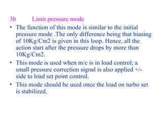
  • 33. 3b Limit pressure mode • The function of this mode is similar to the initial pressure mode .The only difference being that biasing of 10Kg/Cm2 is given in this loop. Hence, all the action start after the pressure drops by more than 10Kg/Cm2. • This mode is used when m/c is in load control; a small pressure correction signal is also applied +/- side to load set point control. • This mode should be used once the load on turbo set is stabilized.
  • 34. PRESSURE CONTROLLER CIRCUIT Actual Pressure ( 0-250 BAR ), Pact ( 0-10V ) Pr ( 0-10V ) hr Pr c ( +4V to + 10 V ) Set Pressure ( 0- 250 BAR ) - + Gain 4V ( Lower limit ) 0.4 V (10 BAR) Initial Pressure Mode
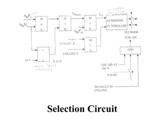
  • 35. 4 Control Transfer • This loop receives the signal from speed controller (hrnc), load controller(hr PC) and pr. controller • a set of Max & Min selection and then final value selected is passed on to position /admission controller • hrnc and hrPC pass through a maximum value selector and the value selected is passed on to first MIN value selection. 10.5v is added in hrnc and this value is also fed to first Min value selector. • The value selected in first Min value selector is passed on to the second MIN value selector along with output of pressure controller output (hr PRC) The value selected here is passed on the position / admission controller.
  • 37. 5 Position/admission Controller • Position Controller is the final control element in EHC. It receives the signal from control transfer • It receives feedback signal from Collins transmitters.Two Collins transmitters are provided • Selection of transmitter is through MIN value selector • Plunger coil supplied in EHC is an integrator type. • There is Provision to switch ON/OFF the voltage supply to plunger coil. Switching ON /OFF can be done only if the output of position controller is > 100%.
  • 38. LOAD SHEDDING RELAY • Load shedding relay is necessary when the hydraulic governor is controlling but is also kept in operation when the EHC is in control to avoid over speeding of turbine . • Upon action of LRR the HPCV & IPCV are closed completely for a short interval(1.4 sec max) • Sudden negative jump in load is detected electrically instantaneously by the load shedding relay when, in 200MW: Load throw off>40% & residual load<15% & frequency>49 Hz • LRR acts therefore earlier on the hydraulic control system i.e. Before HC takes action due to the speed increase
  • 44. CONTROL TRANSFER LOGIG & ADMISSION CONTROLLER -
  • 45. 2790 2940 3060 3210 RPM output +100% -100% 0% Droop of kwu m/c
  • 46. What is Droop? % of frequency change ( % of RPM change) will lead to full travel of Governing valves or full load change. 5% droop means: 5%*50 Hz= 2.5 Hz Will change 500MW. In terms of output total change should take place is 100%