


![Ethernet Technologies
Ethernet comes in many different flavors, with somewhat
bewildering acronyms such as 10BASE-T, 10BASE-2, 100BASE-
T, 1000BASE-LX, and10GBASE-T.
These and many other Ethernet technologies have been
standardized
over the years by the IEEE 802.3 CSMA/CD (Ethernet) working
group [IEEE 802.3 2012].
CDMA/CD protocol nicely solves the multiple access problem.
The standard for Gigabit Ethernet, referred to as IEEE 802.3z,](https://image.slidesharecdn.com/ethernetli-fi-180322044911/85/Ethernet-and-LIFI-9-320.jpg)


Ethernet and LIFI
- 1. Topics ETHERNET LI-FI(Light Fidelity) ROHIT JADHAV T1514
- 2. Ethernet History The original Ethernet LAN was invented in the mid 1970s by Bob Metcalfe and David Boggs. Ethernet was developed at Xerox PARC (Palo Alto Research Center) between 1973 and 1974. The idea was first documented in a memo that Metcalfe wrote on May 22, 1973. In 1976, after the system was deployed at PARC, Metcalfe and Boggs published a seminal paper. Firstly created by Robert Metcalfe in 1979 (3com corporation) 3Com Corporation was a digital electronics manufacturer best known for it computer network products
- 3. What is Ethernet ? Ethernet is a family of computer networking, technologies commonly used in local area networks (LAN), metropolitan area networks(MAN) and wide area networks (WAN). Definition :- A system for connecting a number of computer systems to form a local area network, with protocols to control the passing of information and to avoid simultaneous transmission by two or more systems Ethernet is a link layer protocol in the TCP/IP(transmission control protocol /Internet protocol) Ethernet uses bus topology
- 4. ETHERNET EVOLUTION STANDARD ETHERNET 10Mbps FAST ETHERNET 100Mbps GIGABIT ETHERNET 1Gbps TEN GIGABIT ETHERNET 10Gbps
- 5. First of all two different type of computers and they should be networked also. NIC or network interface cards should be placed in every computer A cable that is called as the Ethernet cable should be connected with the entire computer used in connection. Networking hubs that are used to introduce the systems or the network over network traffic. Hardware components of Ethernet
- 6. A hub is a physical-layer device that acts on individual bits rather than frames. NIC (Network Interface Card ) has small device called transceiver. Transceiver = transmitter + receiver Transceiver checks :- Nobodies transmitting One host transmitting Multiple host have transmitted so there is a collision.
- 8. Computer A,B and C are connected physically by LAN cable Suppose A want to send data B a transceiver checks the voltage of the wire ,if the wire is the wire is free then A will send transmitted . Suppose at the same time B send data to C there will be collision every one including A & B is different and randomly selected after waiting this random time A & B Will retransmit . Is there is another collision they will increase the waiting time exponentially this continuous until successful transmission , this algorithm are called as binary exponential back-of policy the over all Operation called as carrier sense multiple access with collision detect (CSMA/CD) How to work Ethernet ?
- 9. Ethernet Technologies Ethernet comes in many different flavors, with somewhat bewildering acronyms such as 10BASE-T, 10BASE-2, 100BASE- T, 1000BASE-LX, and10GBASE-T. These and many other Ethernet technologies have been standardized over the years by the IEEE 802.3 CSMA/CD (Ethernet) working group [IEEE 802.3 2012]. CDMA/CD protocol nicely solves the multiple access problem. The standard for Gigabit Ethernet, referred to as IEEE 802.3z,
- 10. Ethernet Frame A ethernet frame is a physical layer communications transmission, comprised of 6 fields which are assembled to transmit any higher layer protocol over an Ethernet fabric.
- 11. A IEEE 802.3 Ethernet Frame is composed of 6 segments which are described in detail below:- Preamble: The preamble is not typically used in modern ethernet networks as its function is to provide signal start up time for 10Mbps Ethernet signals. modern 100Mbps, 1000Mbps or 10Gbps ethernet use constant signalling, which avoids the need for the preamble. The preamble, while listed as a part of the actual Ethernet frame is technically not part of the frame as it is added to the front of the frame by the NIC just before the frame is put on the wire. Ethernet Frame (Continued)
- 12. Destination and Source Address: These two sections of the frame are likely the most commonly understood in that they contain the MAC address for the source “transmitting system” and the destination “target system”. Type / Length The type / length field is used to identify what higher-level network protocol is being carried in the frame (example: TCP/IP) Ethernet Frame(Continued)
- 13. Data / Payload The diagram specifies a range between a minimum of 46 bytes and maximum of 1500 bytes. A standard Ethernet frame has a maximum payload of 1500 bytes, frames over 1500 bytes are considered Jumbo Frames. Frame Check Sequence (CRC) The CRC is generated by applying a polynomial to bits which make up the frame at transmission. This same polynomial is used at the receiving station to verify the contents of the frame have not changed in Ethernet Frame (Continued)
- 14. Applications Layer 2 VPNs for IT Infrastructure: Ethernet Layer 2 Virtual Private Networks (VPNs) maximize the performance of existing IT infrastructure increasing network control. Cloud Computing: The deterministic and dynamic service attributes of Ethernet benefit the way cloud computing is used and consumed. Site to Site Access: Provides added performance and higher bandwidth levels along with service standardization at all locations.
- 15. Applications Software-as-a-Service (SaaS), Service Oriented Architecture (SOA): Offers better transparency, standardization at all locations and easier performance management. Video Applications: Provides better quality of service (QoS). Voice: Voice over Internet Protocol (VoIP) is well-known for its cost-savings. Ethernet provides quality of service (QoS) options and improved performance management.
- 16. Applications Distributed Storage Area Networks: Provides added performance and higher bandwidth levels. CCTV: Closed-circuit television (CCTV) – Ethernet connectivity offers consistent cost and ubiquity enabling improved service management. Business Continuity/Disaster Recovery: Ethernet allow business continuity and disaster recovery networks to optimally perform with measurable performance and flexible bandwidth levels.
- 17. Applications Distributed Imaging: Ethernet delivers the higher bandwidth required for distributed imaging systems including picture archiving and communications system (PACS).
- 18. LIGHT FIDELITY(LI-FI) Light based Wi-Fi Light is used instead of radio-waves to transmit information Transceiver fitted LED lamps acts like Wi-Fi modems LED lamps can light a room as well as transmit-receive information Provides illumination as well as data communication
- 19. NEED FOR LI-FI Radio spectrum is congested, but the demand for wireless data doubles each year Issues regarding radio spectrum, such as capacity, availability, efficiency, security are solved using LIFI. Speed of data transmission can be increased.
- 20. OVERCOMING WIFI ISSUES CAPACITY Spectrum is 10,000 times greater than that of radio frequency EFFICIENCY Highly efficient since LED consumes less energy AVAILABILITY Light waves available everywhere. SECURITY Cannot penetrate through walls. Hence data cannot be intercepted.
- 21. VISIBLE LIGHT COMMUNICATION In electromagnetic spectrum, gamma, UV rays are dangerous for human body. IR rays, due to eye safety regulations, are not used
- 22. LIFE OF LIFI Introduced by Professor Herald hass, at the university of Edinburgh. Established in 2011 TED global talk The promotion of idea through TED helped to start a company, Pure Li-Fi Pure Li-Fi, formerly pure VLC, is an original equipment manufacture firm setup to commercialize Li-Fi products for integration with existing LED lighting systems In October 2011, few companies and industries group formed Li-Fi consortium to promote the high speed optical wireless systems
- 23. HOW IT WORKS? Operational procedure is very simple. If LED is ON, digital data „1‟ is transmitted & if LED is OFF, digital data „0‟ is transmitted. LEDs varies in intensity so fast that a human eye cannot detect it. A controller connected at the back side of these LEDs is used to code data. Also called as 5G optical communication.
- 24. IMPLEMENTATION All the data from Internet is streamed into lamp driver. Data from internet is used to modulate the intensity of LED light source. Thus by fast and subtle variations of current, optical output can be made to vary at extremely high speed. The photo detector picks up the signal. The receiver dongle then converts the tiny changes in amplitude into a data stream.
- 25. LI-FI NETWORKS Li-Fi connector and router are the main components for a network Room connector: Optical signals cannot penetrate through walls, in order to provide an optical WLAN, rooms need to be connected with each other Li-Fi room connector is a replicator, which sends the data stream from one side of the wall to the other side via an optical fiber. For smaller rooms, connector act as the only Li-Fi hotspot in the room
- 26. LI-FI ROUTER Serves as a connector to external link like DSL. Covers a radius of about 20 meters The transmission speed is 100 Mbps. Suitable for small office or home use
- 27. APPLICATIONS Li-Fi can be used in sensitive areas such as aircrafts for data transmission without causing interference. Places where it is difficult to lay optical fibers like operation theaters Traffic scenarios, thereby reducing accidents. Underwater applications where radio waves cannot propagate. Industries like petrochemical plants, nuclear power plants , petrol pumps etc
- 28. TRAFFIC SCENARIO In traffic scenario, Li-Fi can be used to communicate with the LED lights of cars . Cars can have LED-based headlights, backlights and can communicate with each other. This might prevent accidents, by exchanging information, when the vehicles are too close Using Li-Fi, Street lights can be used to send information about the road condition to the car.
- 29. LECTURE / SEMINAR HALLS Downloading notes from blogs of teachers Often it is necessary to download lecture notes from the blogs of respective teachers. With Li-Fi, the download can be done in the hall itself Interactive classroom with interconnected devices The classroom will be more interactive with the real-time interconnectivity between 500 devices Sharing views & queries with the entire class Each person‟s queries, views and clarifications can be shared not only with the teacher, but with the entire class.
- 30. INDUSTRIES Used in RF restricted environments like chemical industries, nuclear power plants, petrol pumps
- 31. HOME AND SMALL OFFICES In home and small offices, Li-Fi can be used to communicate with devices like Laptops Internet access HD video streaming Printer
- 32. AIRCRAFTS The whole airways communication are performed on the basis of radio waves. Hence passengers face the problem in communication media. This problem can be overcome by using Li-Fi, since light waves will not interfere with radio waves.
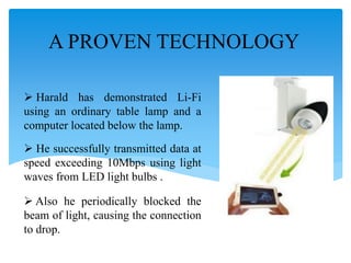
- 33. A PROVEN TECHNOLOGY Harald has demonstrated Li-Fi using an ordinary table lamp and a computer located below the lamp. He successfully transmitted data at speed exceeding 10Mbps using light waves from LED light bulbs . Also he periodically blocked the beam of light, causing the connection to drop.
- 34. VLC SMARTPHONES The first VLC Smartphone was presented by Consumer Electronics in January, 2014 The phone uses Wysips connect – a clear thin layer of crystal glass is added to the small screens Smartphone makes them solar powered. Smartphone could get 15% more battery life in a day Can communicate using Li-Fi.
- 35. ADVANTAGES Data rate greater than 10 Gbps; Theoretically allowing HD film to be downloaded in 30 seconds Can be used anywhere, even in RF restricted areas; Since light waves will not interfere with radio waves. Mostly LED light bulbs are used, which consumes less energy. Hence cost efficient. As light waves cannot penetrate through walls, the data cannot be intercepted; Thus provides secured communication. Efficient alternative to radio based wireless; since it is quick and reliable.
- 36. LIMITATIONS Visible light cannot penetrate through solid objects. A major challenge of Li-Fi is how the receiving device will transmit back to transmitter. Interferences from external light sources like sunlight, in the path of transmission will cause interruption in the communication. Data transmission can be easily blocked by any object placed in front of LED source.
- 37. CONCLUSION Thus, if Li-Fi technology can be put into practical use, every bulb can be used as an alternative to Wi-Fi hotspots. It provides simple, faster and efficient wireless data communication. Li-Fi will make us to proceed towards the cleaner, greener, safer and brighter future.