SlideShare a Scribd company logo
ModelBuilder - Executing
Tools Tutorial
Copyright © 1995-2010 Esri All rights reserved.
Table of Contents
Tutorial: Executing tools in ModelBuilder . . . . . . . . . . . . . . . . . . . . . . . . . 3
ModelBuilder - Executing Tools Tutorial
Copyright © 1995-2010 Esri. All rights reserved. 2
Tutorial: Executing tools in ModelBuilder
This tutorial takes you step-by-step through creating a model and executing
tools in ModelBuilder. You start by adding a tool to ModelBuilder and
supplying values for the tool's parameters. This constructs a process. A
model is built by connecting processes.
This tutorial builds a very simple model that identifies the vegetation types
near proposed roads. In the model, the roads are first buffered using values
from a distance field in the roads attribute table. The output from the Buffer tool is used to clip the vegetation
data to create a dataset of vegetation types within the buffer polygons.
The tutorial is composed of six broad steps:
Steps:
1. Copy tutorial data
2. Open the map document
3. Create a new model
4. Add tools and data to the model
5. Fill in the tool parameters
6. Run the model
7. Save the model
1—Copying tutorial data
It is assumed that you have installed ArcGIS Desktop (ArcView, ArcEditor, or ArcInfo) before you begin this
tutorial. The data required for this tutorial (included on the ArcGIS Desktop CD) by default is installed in
C:arcgisArcTutor. The tutorial scenario is fictitious, and the original data has been adapted for the
tutorial.
Steps:
1. To avoid corrupting the original data, copy the ModelBuilder folder from
C:arcgisArcTutor to the C drive on your computer. If you are copying the data to another
drive or location, make sure to use that location for all the steps below.
2—Opening the map document
Browse to the C:ModelBuilder folder in Windows Explorer and double click the Extract Vegetation.mxd.
This will start ArcMap and open the map document, or
Steps:
1. Start ArcMap by clicking Start > All Programs > ArcGIS > ArcMap 10.
2. On the ArcMap - Getting Started dialog box, click Existing Maps > Browse for more.
The Open ArcMap Document dialog box appears.
Complexity:
Beginner
Data Requirement:
ArcGIS Tutorial Data Setup
Goal:
Learn how to execute tools in
ModelBuilder.
ModelBuilder - Executing Tools Tutorial
Copyright © 1995-2010 Esri. All rights reserved. 3
3. Browse to C:ModelBuilder folder, select Extract Vegetation.mxd, and click Open.
This opens the Extract Vegetation.mxd.
3—Creating a new model
Steps:
1. Click the ModelBuilder button on the ArcMap Standard toolbar.
This opens the ModelBuilder window for editing.
You can also create a new model by right-clicking an existing toolbox and choosing New >
Model. This creates a model in the toolbox with a default name and opens the model for
editing.
4—Adding tools and data to a model
Now that the model is open for editing, you will add two tools using the Search window:
Steps:
1. In ArcMap, click Geoprocessing > Search For Tools.
This opens a Search window that you can dock anywhere in ArcMap.
2. On the Search window, type Buffer, then click the Search button .
The Buffer tool is listed along with other search items.
3. Drag the search item Buffer (Analysis) (which represents the Buffer tool found in the Analysis
toolbox) onto the ModelBuilder canvas in the white space.
ModelBuilder - Executing Tools Tutorial
Copyright © 1995-2010 Esri. All rights reserved. 4
This adds the tool and the output data variable to the model. The output variable is connected
to the tool by a connector. Both the tool and output data are empty (without color) as none of
the tool parameters have been supplied.
4. Search for and add the Clip tool in the Analysis toolbox in a similar manner. If the two tools
overlap, click the Auto Layout button on the ModelBuilder toolbar to arrange the tools.
There are two other methods to add tools in a model that are not used in this tutorial, but have
been listed to introduce you to them:
• In the Catalog window, navigate to Toolboxes > System Toolboxes > Analysis Tools
> Proximity. You can select Buffer and drag the tool onto the ModelBuilder canvas in
the white space.
• On the ModelBuilder Standard toolbar you can click the Add Data or Tool button ,
and navigate to Toolboxes > System Toolboxes > Analysis Tools > Proximity.
Select the Buffer tool and click Add.
ModelBuilder - Executing Tools Tutorial
Copyright © 1995-2010 Esri. All rights reserved. 5
5—Filling in tool parameters
Now that the tools are added to the model, you will fill in the tool parameters.
Steps:
1. In ModelBuilder, double-click the Buffer tool to open its tool dialog box.
2. For the Input Features parameter, click the browse button and navigate to the input
geodatabase (C:ModelBuilderToolDataInput.gdb).
3. Choose the PlanA_Roads feature class and click Add.
4. Once you fill in the input features, the Output Feature Class parameter is automatically
generated and filled in for you. Replace this autogenerated output name by clicking the
Browse button for the Output Feature Class parameter. Navigate to the output geodatabase
in the ModelBuilder folder (C:ModelBuilderScratchOutput.gdb), type BufferedFC
for the output name, then click Save.
5. For the Distance parameter, choose the Field option and choose the Distance field from the
drop-down list.
6. Click OK. (You don't need to fill in any other parameters.)
The input data is added as a variable to the model (the blue oval in the above illustration) and
is automatically connected to the Buffer. The input variable (the blue oval), the tool (the yellow
rectangle), and the output variable (the green oval) change colors to indicate that all parameter
values have been supplied and the tool is ready to run. Note that clicking OK on the tool dialog
box does not execute the tool in ModelBuilder.
When data or tools are added to a model, they are referred to as model elements. There are
three basic types of elements: variables (such as datasets), tools, and connectors.
7. Now double-click Clip to open its tool dialog box.
8. For the Input Features parameter, click the Browse button and navigate to the input
geodatabase (C:ModelBuilderToolDataInput.gdb).
9. Choose the vegtype feature class and click Add.
ModelBuilder - Executing Tools Tutorial
Copyright © 1995-2010 Esri. All rights reserved. 6
10. For the Clip Feature parameter, click the arrow and choose BufferedFC from the drop down
list. The blue recycle symbol means that BufferedFC is a variable in the model. This
variable was created in the model when you added the Buffer tool.
11. Click the browse button for the Output Feature Class parameter, navigate to the output
geodatabase (C:ModelBuilderScratchOutput.gdb), type ClippedFC for the
dataset name, then click Save.
12. Click OK on the Clip tool dialog box.
The output variable of the Buffer tool is automatically connected (using a connector) as an
input to Clip, as illustrated below.
6—Running the model
After all the parameters of the tools have been filled in, the model is ready to run.
Steps:
1. Before you run the model, select the ClippedFC variable, right-click, then click the Add To
Display option. Setting this option ensures that when the model is run from ModelBuilder, the
output ClippedFC will be added to the display in ArcMap for quick viewing of the results.
2. From the ModelBuilder menu, click Model > Run Entire Model.
The model runs and the output is added to the display. After the model has finished running,
both the tools (the yellow rectangles) and output variables (the green ovals) show a drop
shadow around them indicating that these tools have been run.
ModelBuilder - Executing Tools Tutorial
Copyright © 1995-2010 Esri. All rights reserved. 7
Running the model on different roads
To run the model on different roads (such as PlanB or PlanC feature classes), you have two choices:
1. Double-click Buffer and navigate to another feature class, or
2. Drag the data from the Catalog window onto the ModelBuilder canvas to create a new data
variable, then connect this variable to Buffer. Follow the steps below to see how this works.
Steps:
1. On the ArcMap menu, select Geoprocessing > Geoprocessing Options.
a. Ensure that the check box next to When connecting elements, display valid
parameters when more than one is available is checked.
b. Click OK.
2. Navigate to the input geodatabase in the Catalog window.
3. Choose the PlanB_Roads feature class and drag it onto the ModelBuilder canvas.
4. Click the Connect button , then do the following:
a. Click the PlanB_Roads variable element.
b. Click the Buffer tool element. A shortcut menu appears containing the choices of
available parameters for the tool.
c. Choose the Input Features parameter from the list.
This connects the PlanB_Roads variable to Buffer and automatically disconnects the
PlanA_Roads variable that was previously connected to the tool. The model elements lose
their drop shadow, signifying that the model has not been run with the new variable you
added.
5. Double-click Buffer and choose the correct distance field from the PlanB_Roads feature
class.
6. Run the model with Model > Run Entire Model.
The model runs and the output is added to the display. After the model has finished running,
both the tools and output variables show a drop shadow around them indicating that these
tools have been run. The existing output ClippedFC layer (from the previous run with
PlanA_Roads) in the ArcMap table of contents is updated with the results from
PlanB_Roads.
7—Saving a model
Saving is the last step for this tutorial. You will use the saved model in the Creating tools with ModelBuilder
tutorial.
Steps:
1. Click the Save tool on the ModelBuilder toolbar and navigate to C:ModelBuilder.
2. A model can only be saved in a toolbox. Click the New Toolbox icon on the navigation
window.
A toolbox with a default name is added in the workspace.
ModelBuilder - Executing Tools Tutorial
Copyright © 1995-2010 Esri. All rights reserved. 8
3. Change the name to MyTools.tbx.
4. Select MyTools.tbx and click Save to save the model with the default name (Model).
Additional analysis
If you want to do some analysis with the model, you can add the Summary Statistics tool to get a summary
table of affected area by vegetation type within the buffer polygons around the proposed roads.
Steps:
1. Use PlanA_Roads as input in the Buffer tool for this analysis.
2. Find the Summary Statistics tool in the Search window.
3. Drag the tool into the model.
4. Double-click the Summary Statistics element to open the tool dialog box.
5. For the Input Table parameter, click the arrow and choose ClippedFC with a blue recycle icon
next to it from the drop down list. This recycle icon means it is a variable in the model.
6. For the Output Table parameter, browse to the output geodatabase
(C:ModelBuilderScratchOutput.gdb), type AffectedVegetation for the name,
then click Save.
7. For the Statistic Field(s) parameter, choose Shape_Area from the list.
8. Click the cell next to Shape_Area under Statistic Type and choose SUM from the drop down
list.
9. For the Case field parameter, choose VEG_TYPE from the list.
The completed Summary Statistics dialog box is illustrated below.
ModelBuilder - Executing Tools Tutorial
Copyright © 1995-2010 Esri. All rights reserved. 9
10. Click OK.
11. Confirm that the Add to Display option is checked for ClippedFC by right clicking it.
12. Right click and check the Add to Display option for the AffectedVegetation variable. This will
add the ouput to the display after the model runs.
13. Run the model.
The output ClippedFC and the AffectedVagetation table is added to display in the ArcMap
table of contents.
14. Open the table by right-clicking and clicking Open.
The table shows a summary of area by vegetation type within the buffer polygons that will be
affected by the proposed roads for plan A.
ModelBuilder - Executing Tools Tutorial
Copyright © 1995-2010 Esri. All rights reserved. 10

More Related Content

PPTX
Model builder in ARC GIS
PPTX
Sample instrument using lab view abhijeet agarwal-1
DOC
222066369 clad-study-guide
PPT
GUI -THESIS123
PPTX
GUI in Matlab - 2
PPTX
GUI in Matlab - 1
PPTX
PPTX
WEKA: The Knowledge Flow Interface
Model builder in ARC GIS
Sample instrument using lab view abhijeet agarwal-1
222066369 clad-study-guide
GUI -THESIS123
GUI in Matlab - 2
GUI in Matlab - 1
WEKA: The Knowledge Flow Interface

What's hot (14)

PPT
Scmad Chapter05
PDF
NX QUESTIONS
PDF
CREO / PROE QUESTIONS
PDF
Automatic ground truth generation for image sequences
PDF
Coord transform 082014
PDF
FEAColor3DPrinting
PDF
Structural components based verification process for fea models
PDF
Risa education tut
PPTX
WEKA: The Experimenter
PDF
The 7 basic quality tools through minitab 18
PPTX
Iteman. madiha
PDF
Characterization of a 2D Geometry Using C++ Interface
PPT
PPT
Session4 applets
Scmad Chapter05
NX QUESTIONS
CREO / PROE QUESTIONS
Automatic ground truth generation for image sequences
Coord transform 082014
FEAColor3DPrinting
Structural components based verification process for fea models
Risa education tut
WEKA: The Experimenter
The 7 basic quality tools through minitab 18
Iteman. madiha
Characterization of a 2D Geometry Using C++ Interface
Session4 applets
Ad

Viewers also liked (9)

PPTX
Information-seeking Behaviour of LGBTQ health professionals
PDF
Suicide HS
PDF
Final presentation
PPT
Final presentation
PDF
Cc 011210 fewer kim maufas ap courses
PDF
020910 fewer students lgbtq wth amends incorporated maufas championed
PDF
Dd 051110 superintendent proposal hs bd policy revised -maufas championed
PPS
Sunu1
PPTX
LGBTQ: Stigma Bullying and Depression
Information-seeking Behaviour of LGBTQ health professionals
Suicide HS
Final presentation
Final presentation
Cc 011210 fewer kim maufas ap courses
020910 fewer students lgbtq wth amends incorporated maufas championed
Dd 051110 superintendent proposal hs bd policy revised -maufas championed
Sunu1
LGBTQ: Stigma Bullying and Depression
Ad

Similar to Executing tools-in-modelbuilder-tutorial (20)

PDF
Model builder in_arcgis
PDF
Publishing geoprocessing-services-tutorial
PDF
Intro to ArcGIS ModelBuilder
DOCX
Solid Modeling Assignment EGR 201-100 Spring 2018 .docx
PDF
Hv 4000 querying results
PDF
Arena tutorial
PDF
lecture_slides_esteem2019-231.pdf
PPTX
Basic commands of ArcGIS
PPT
Spreadsheet Auditing
PPTX
AgilentHPLC_SOP_Base_1_InfinitySeries.pptx
PPTX
Orcad Capture - Schematic Design Tutorial
PPTX
Vb6.0 intro
PDF
Normal Modal Analysis in Hypermesh
PPTX
IT Practical File (2).pptx
PDF
Aragaw Gebremedhin auto cad lecture notes
PPTX
Ansys Workbench Basics
DOCX
COIT20245, 2016 Term One - Page 1 of 9 Assessment detail.docx
DOCX
GEIT 3341 DATABASE I LAB 2 GEIT 3341 Database I
PPT
PDF
Mathcad
Model builder in_arcgis
Publishing geoprocessing-services-tutorial
Intro to ArcGIS ModelBuilder
Solid Modeling Assignment EGR 201-100 Spring 2018 .docx
Hv 4000 querying results
Arena tutorial
lecture_slides_esteem2019-231.pdf
Basic commands of ArcGIS
Spreadsheet Auditing
AgilentHPLC_SOP_Base_1_InfinitySeries.pptx
Orcad Capture - Schematic Design Tutorial
Vb6.0 intro
Normal Modal Analysis in Hypermesh
IT Practical File (2).pptx
Aragaw Gebremedhin auto cad lecture notes
Ansys Workbench Basics
COIT20245, 2016 Term One - Page 1 of 9 Assessment detail.docx
GEIT 3341 DATABASE I LAB 2 GEIT 3341 Database I
Mathcad

Executing tools-in-modelbuilder-tutorial

  • 1. ModelBuilder - Executing Tools Tutorial Copyright © 1995-2010 Esri All rights reserved.
  • 2. Table of Contents Tutorial: Executing tools in ModelBuilder . . . . . . . . . . . . . . . . . . . . . . . . . 3 ModelBuilder - Executing Tools Tutorial Copyright © 1995-2010 Esri. All rights reserved. 2
  • 3. Tutorial: Executing tools in ModelBuilder This tutorial takes you step-by-step through creating a model and executing tools in ModelBuilder. You start by adding a tool to ModelBuilder and supplying values for the tool's parameters. This constructs a process. A model is built by connecting processes. This tutorial builds a very simple model that identifies the vegetation types near proposed roads. In the model, the roads are first buffered using values from a distance field in the roads attribute table. The output from the Buffer tool is used to clip the vegetation data to create a dataset of vegetation types within the buffer polygons. The tutorial is composed of six broad steps: Steps: 1. Copy tutorial data 2. Open the map document 3. Create a new model 4. Add tools and data to the model 5. Fill in the tool parameters 6. Run the model 7. Save the model 1—Copying tutorial data It is assumed that you have installed ArcGIS Desktop (ArcView, ArcEditor, or ArcInfo) before you begin this tutorial. The data required for this tutorial (included on the ArcGIS Desktop CD) by default is installed in C:arcgisArcTutor. The tutorial scenario is fictitious, and the original data has been adapted for the tutorial. Steps: 1. To avoid corrupting the original data, copy the ModelBuilder folder from C:arcgisArcTutor to the C drive on your computer. If you are copying the data to another drive or location, make sure to use that location for all the steps below. 2—Opening the map document Browse to the C:ModelBuilder folder in Windows Explorer and double click the Extract Vegetation.mxd. This will start ArcMap and open the map document, or Steps: 1. Start ArcMap by clicking Start > All Programs > ArcGIS > ArcMap 10. 2. On the ArcMap - Getting Started dialog box, click Existing Maps > Browse for more. The Open ArcMap Document dialog box appears. Complexity: Beginner Data Requirement: ArcGIS Tutorial Data Setup Goal: Learn how to execute tools in ModelBuilder. ModelBuilder - Executing Tools Tutorial Copyright © 1995-2010 Esri. All rights reserved. 3
  • 4. 3. Browse to C:ModelBuilder folder, select Extract Vegetation.mxd, and click Open. This opens the Extract Vegetation.mxd. 3—Creating a new model Steps: 1. Click the ModelBuilder button on the ArcMap Standard toolbar. This opens the ModelBuilder window for editing. You can also create a new model by right-clicking an existing toolbox and choosing New > Model. This creates a model in the toolbox with a default name and opens the model for editing. 4—Adding tools and data to a model Now that the model is open for editing, you will add two tools using the Search window: Steps: 1. In ArcMap, click Geoprocessing > Search For Tools. This opens a Search window that you can dock anywhere in ArcMap. 2. On the Search window, type Buffer, then click the Search button . The Buffer tool is listed along with other search items. 3. Drag the search item Buffer (Analysis) (which represents the Buffer tool found in the Analysis toolbox) onto the ModelBuilder canvas in the white space. ModelBuilder - Executing Tools Tutorial Copyright © 1995-2010 Esri. All rights reserved. 4
  • 5. This adds the tool and the output data variable to the model. The output variable is connected to the tool by a connector. Both the tool and output data are empty (without color) as none of the tool parameters have been supplied. 4. Search for and add the Clip tool in the Analysis toolbox in a similar manner. If the two tools overlap, click the Auto Layout button on the ModelBuilder toolbar to arrange the tools. There are two other methods to add tools in a model that are not used in this tutorial, but have been listed to introduce you to them: • In the Catalog window, navigate to Toolboxes > System Toolboxes > Analysis Tools > Proximity. You can select Buffer and drag the tool onto the ModelBuilder canvas in the white space. • On the ModelBuilder Standard toolbar you can click the Add Data or Tool button , and navigate to Toolboxes > System Toolboxes > Analysis Tools > Proximity. Select the Buffer tool and click Add. ModelBuilder - Executing Tools Tutorial Copyright © 1995-2010 Esri. All rights reserved. 5
  • 6. 5—Filling in tool parameters Now that the tools are added to the model, you will fill in the tool parameters. Steps: 1. In ModelBuilder, double-click the Buffer tool to open its tool dialog box. 2. For the Input Features parameter, click the browse button and navigate to the input geodatabase (C:ModelBuilderToolDataInput.gdb). 3. Choose the PlanA_Roads feature class and click Add. 4. Once you fill in the input features, the Output Feature Class parameter is automatically generated and filled in for you. Replace this autogenerated output name by clicking the Browse button for the Output Feature Class parameter. Navigate to the output geodatabase in the ModelBuilder folder (C:ModelBuilderScratchOutput.gdb), type BufferedFC for the output name, then click Save. 5. For the Distance parameter, choose the Field option and choose the Distance field from the drop-down list. 6. Click OK. (You don't need to fill in any other parameters.) The input data is added as a variable to the model (the blue oval in the above illustration) and is automatically connected to the Buffer. The input variable (the blue oval), the tool (the yellow rectangle), and the output variable (the green oval) change colors to indicate that all parameter values have been supplied and the tool is ready to run. Note that clicking OK on the tool dialog box does not execute the tool in ModelBuilder. When data or tools are added to a model, they are referred to as model elements. There are three basic types of elements: variables (such as datasets), tools, and connectors. 7. Now double-click Clip to open its tool dialog box. 8. For the Input Features parameter, click the Browse button and navigate to the input geodatabase (C:ModelBuilderToolDataInput.gdb). 9. Choose the vegtype feature class and click Add. ModelBuilder - Executing Tools Tutorial Copyright © 1995-2010 Esri. All rights reserved. 6
  • 7. 10. For the Clip Feature parameter, click the arrow and choose BufferedFC from the drop down list. The blue recycle symbol means that BufferedFC is a variable in the model. This variable was created in the model when you added the Buffer tool. 11. Click the browse button for the Output Feature Class parameter, navigate to the output geodatabase (C:ModelBuilderScratchOutput.gdb), type ClippedFC for the dataset name, then click Save. 12. Click OK on the Clip tool dialog box. The output variable of the Buffer tool is automatically connected (using a connector) as an input to Clip, as illustrated below. 6—Running the model After all the parameters of the tools have been filled in, the model is ready to run. Steps: 1. Before you run the model, select the ClippedFC variable, right-click, then click the Add To Display option. Setting this option ensures that when the model is run from ModelBuilder, the output ClippedFC will be added to the display in ArcMap for quick viewing of the results. 2. From the ModelBuilder menu, click Model > Run Entire Model. The model runs and the output is added to the display. After the model has finished running, both the tools (the yellow rectangles) and output variables (the green ovals) show a drop shadow around them indicating that these tools have been run. ModelBuilder - Executing Tools Tutorial Copyright © 1995-2010 Esri. All rights reserved. 7
  • 8. Running the model on different roads To run the model on different roads (such as PlanB or PlanC feature classes), you have two choices: 1. Double-click Buffer and navigate to another feature class, or 2. Drag the data from the Catalog window onto the ModelBuilder canvas to create a new data variable, then connect this variable to Buffer. Follow the steps below to see how this works. Steps: 1. On the ArcMap menu, select Geoprocessing > Geoprocessing Options. a. Ensure that the check box next to When connecting elements, display valid parameters when more than one is available is checked. b. Click OK. 2. Navigate to the input geodatabase in the Catalog window. 3. Choose the PlanB_Roads feature class and drag it onto the ModelBuilder canvas. 4. Click the Connect button , then do the following: a. Click the PlanB_Roads variable element. b. Click the Buffer tool element. A shortcut menu appears containing the choices of available parameters for the tool. c. Choose the Input Features parameter from the list. This connects the PlanB_Roads variable to Buffer and automatically disconnects the PlanA_Roads variable that was previously connected to the tool. The model elements lose their drop shadow, signifying that the model has not been run with the new variable you added. 5. Double-click Buffer and choose the correct distance field from the PlanB_Roads feature class. 6. Run the model with Model > Run Entire Model. The model runs and the output is added to the display. After the model has finished running, both the tools and output variables show a drop shadow around them indicating that these tools have been run. The existing output ClippedFC layer (from the previous run with PlanA_Roads) in the ArcMap table of contents is updated with the results from PlanB_Roads. 7—Saving a model Saving is the last step for this tutorial. You will use the saved model in the Creating tools with ModelBuilder tutorial. Steps: 1. Click the Save tool on the ModelBuilder toolbar and navigate to C:ModelBuilder. 2. A model can only be saved in a toolbox. Click the New Toolbox icon on the navigation window. A toolbox with a default name is added in the workspace. ModelBuilder - Executing Tools Tutorial Copyright © 1995-2010 Esri. All rights reserved. 8
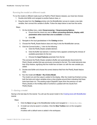
  • 9. 3. Change the name to MyTools.tbx. 4. Select MyTools.tbx and click Save to save the model with the default name (Model). Additional analysis If you want to do some analysis with the model, you can add the Summary Statistics tool to get a summary table of affected area by vegetation type within the buffer polygons around the proposed roads. Steps: 1. Use PlanA_Roads as input in the Buffer tool for this analysis. 2. Find the Summary Statistics tool in the Search window. 3. Drag the tool into the model. 4. Double-click the Summary Statistics element to open the tool dialog box. 5. For the Input Table parameter, click the arrow and choose ClippedFC with a blue recycle icon next to it from the drop down list. This recycle icon means it is a variable in the model. 6. For the Output Table parameter, browse to the output geodatabase (C:ModelBuilderScratchOutput.gdb), type AffectedVegetation for the name, then click Save. 7. For the Statistic Field(s) parameter, choose Shape_Area from the list. 8. Click the cell next to Shape_Area under Statistic Type and choose SUM from the drop down list. 9. For the Case field parameter, choose VEG_TYPE from the list. The completed Summary Statistics dialog box is illustrated below. ModelBuilder - Executing Tools Tutorial Copyright © 1995-2010 Esri. All rights reserved. 9
  • 10. 10. Click OK. 11. Confirm that the Add to Display option is checked for ClippedFC by right clicking it. 12. Right click and check the Add to Display option for the AffectedVegetation variable. This will add the ouput to the display after the model runs. 13. Run the model. The output ClippedFC and the AffectedVagetation table is added to display in the ArcMap table of contents. 14. Open the table by right-clicking and clicking Open. The table shows a summary of area by vegetation type within the buffer polygons that will be affected by the proposed roads for plan A. ModelBuilder - Executing Tools Tutorial Copyright © 1995-2010 Esri. All rights reserved. 10