


![Kinetics of Particles: Impact
Example:
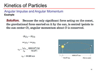
Energy is conserved during free fall:
Initial and final velocities of the ram can be calculated from:
Conservation of the momentum of the system of ram and pile:
G1 = G2
T1 V1 T2 V2 or E1 E2
vp’ = 2.55 m/s [impulses of the weights are neglected]
Coefficient of Restitution
Loss of energy due to impact can be calculated from difference in KE of system
KE just before impact: T = ½ (800)(6.26)2 = 15675 J
Since the energy is conserved this can also be calculated from PE=mgh
KE just after impact: T’ = ½ (800)(1.401)2 + ½ (2400)(2.55)2 = 8588 J
% loss of energy: [(15675-8588)/15675]x(100) = 45.2%
30](https://image.slidesharecdn.com/lecture15-240116181801-1a9a26d4/85/Lecture-15-hii-ni-special-kwa-dynamics-pdf-30-320.jpg)
Lecture 15 hii ni special kwa dynamics.pdf
- 1. Kinetics of Particles :: Impulse and Momentum Third approach to solution of Kinetics problems •Integrate the equation of motion with respect to time (rather than disp.) •Cases where the applied forces act for a very short period of time (e.g., Impact loads) or over specified intervals of time Linear Impulse and Linear Momentum Fixed Origin Resultant of all forces acting on a particle equals its time rate of change of linear momentum Invariability of mass with time!!! 1
- 2. Kinetics of Particles Linear Impulse and Linear Momentum Three scalar components of the eqn: Linear Impulse-Momentum Principle •Describes the effect of resultant force on linear momentum of the particle over a finite period of time Multiplying the eqn by dt ∑F dt = dG and integrating from t1 to t2 G1 = linear momentum at t1 = mv1 G2 = linear momentum at t1 = mv2 The product of force and time is defined as Linear Impulse of the Force. Alternatively: Initial linear momentum of the body plus the linear impulse applied to it equals its final linear momentum Impulse integral is a vector!! 2
- 3. Kinetics of Particles Linear Impulse and Momentum Impulse-Momentum Equation It is necessary to write this eqn in component form and then combine the integrated components: The three scalar impulse- momentum eqns are completely independent completely independent Impulse-Momentum Diagram In the middle drawing linear impulses due to all external forces should be included (except for those forces whose magnitudes 6 are negligible) Impulse-Momentum diagrams can also show the components
- 4. Kinetics of Particles Linear Impulse and Linear Momentum Impulsive Forces: Large forces of short duration (e.g., hammer impact) •In some cases Impulsive forces constant over time they can be brought outside the linear impulse integral. Non-impulsive Forces: can be neglected in comparison with the impulsive forces (e.g., weight of small bodies) In few cases, graphical or numerical integration is required to be performed. The impulse of this force from t1 to t2 is the shaded area under the curve Conservation of Linear Momentum If resultant force acting on a particle is zero during an interval of time, the impulse momentum equation requires that its linear momentum G remains constant. The linear momentum of the particle is said to be conserved (in any or all dirn). This principle is also applicable for motion of two interacting particles with equal and opposite interactive forces 4
- 5. Kinetics of Particles: Linear Impulse and Linear Momentum Example Solution: Construct the impulse-momentum diagram Construct the impulse-momentum diagram 5
- 6. Kinetics of Particles: Linear Impulse and Linear Momentum Example Solution: Using the impulse-momentum eqns: The velocity v2: 6
- 7. Kinetics of Particles: Linear Impulse and Linear Momentum Example Solution: The force of impact is internal to the system composed of the block and the bullet. Further, no other external force the block and the bullet. Further, no other external force acts on the system in the plane of the motion. Linear momentum of the system is conserved G1 = G2 Final velocity and direction: 7
- 8. Kinetics of Particles Angular Impulse and Angular Momentum Velocity of the particle is Momentum of the particle: Moment of the linear momentum vector mv about the origin O is defined as Angular Momentum HO of P about O and is given by: Fixed Origin Scalar components of angular momentum: 8
- 9. Kinetics of Particles Angular Impulse and Angular Momentum A 2-D representation of vectors in plane A is shown: Fixed Origin Magnitude of the moment of mv @ O = linear momentum mv times the moment arm HO = mvr sinθ This is the magnitude of the cross product HO = r x mv Units of Angular Momentum: kg.(m/s).m = kg.m2/s or N.m.s 9
- 10. Kinetics of Particles Angular Impulse and Angular Momentum Rate of Change of Angular Momentum - To relate moment of forces and angular momentum Moment of resultant of all forces acting on P @ origin: Differentiating with time: Fixed Origin Moment of all forces @ O = time rate of change of angular momentum Scalar components: v and mv are parallel vectors v x mv = 0 Using this vector equation, moment of forces and angular momentum are related 10
- 11. Kinetics of Particles Angular Impulse and Angular Momentum Angular Impulse-Momentum Principle -This eqn gives the instantaneous relation between moment and time rate of change of angular momentum Integrating: The product of moment and time is defined as the angular impulse. The total angular impulse on m about the fixed point O equals the corresponding change in the angular momentum of m about O. Alternatively: Initial angular momentum of the particle plus the angular impulse applied to it equals the final angular momentum. 11
- 12. Kinetics of Particles Angular Impulse and Angular Momentum Angular Impulse-Momentum Principle In the component form: The x-component of this eqn: Similarly other components can be written Plane Motion Applications - In most applications, plane motions are encountered instead of 3-D motion. - Simplifying the eqns - Simplifying the eqns Using the scalar form of the principle betn 1 and 2: 12
- 13. Kinetics of Particles Angular Impulse and Angular Momentum Conservation of Angular Momentum If the resulting moment @ a fixed point O of all forces acting on a particle is zero during an interval of time, the angular momentum of the particle about that point remain constant. Principle of Conservation of Angular Momentum Also valid for motion of two interacting particles with equal and opposite interacting forces 13
- 14. Kinetics of Particles Angular Impulse and Angular Momentum Example Solution 14
- 15. Kinetics of Particles Angular Impulse and Angular Momentum Example 15
- 16. Kinetics of Particles Angular Impulse and Angular Momentum Example 16
- 17. Kinetics of Particles Angular Impulse and Angular Momentum Example 17
- 18. Kinetics of Particles Angular Impulse and Angular Momentum 18
- 19. Kinetics of Particles Angular Impulse and Angular Momentum Example 19
- 20. Kinetics of Particles Angular Impulse and Angular Momentum Example 20
- 21. Kinetics of Particles Impact • Collision between two bodies during a very short period of time. • Generation of large contact forces (impulsive) acting over a very short interval of time. • Complex phenomenon (material deformation and recovery, generation of heat and sound) • Line of Impact is the common normal to the surfaces in contact during impact. Impact primarily classified as two types: Central Impact: Mass centers of two colliding bodies are located on line of Central Impact: Mass centers of two colliding bodies are located on line of impact Current chapter deals with central impact of two particles. Eccentric Impact: Mass centers are not located on line of impact. Central Impact Eccentric Impact 21
- 22. Kinetics of Particles Central Impact - Can be classified into two types Direct Central Impact (or Direct Impact) • Velocities of the two particles are directed along the line of impact • Direction of motion of the particles will also be along the line of impact Oblique Central Impact (or Oblique Impact) • Velocity and motion of one or both particles is at an angle with the line of impact. • Initial and final velocities are not parallel. • Initial and final velocities are not parallel. Direct Central Impact Oblique Central Impact 22
- 23. Kinetics of Particles: Impact Direct Central Impact Collinear motion of two spheres (v1 > v2) • Collision occurs with contact forces directed along the line of impact (line of centers) • Deformation of spheres increases until contact area ceases to increase. Both spheres move with the same velocity. • Period of restoration during which the contact area decreases to zero • After the impact, spheres will have different • After the impact, spheres will have different velocities (v’1 & v’2) with v’1 < v’2 During impact, contact forces are equal and opposite. Further, there are no impulsive external forces linear momentum of the system remains unchanged. Applying the law of conservation of linear momentum: Assumptions • Particles are perfectly smooth and frictionless. • Impulses created by all forces (other than the internal forces of contact) are negligible compared to the impulse created by the internal impact force. • No appreciable change in position of mass centers during the impact. 23
- 24. Kinetics of Particles: Impact Coefficient of Restitution The momentum eqn contains 2 unknowns v’1 & v’2 (assuming that v1 & v2 are known) Another equation is required Coefficient of Restitution (e) e magnitude of the Restoration Impulse magnitude of the Deformation Impulse magnitude of the Deformation Impulse Using the definition of impulse: Fr and Fd = magnitudes of the contact forces during the restoration and deformation periods. t0 = time for the deformation t = total time of contact Further using Linear Impulse-Momentum Principle, we can write this equation in terms of change in momentum 24
- 25. Kinetics of Particles: Impact Coefficient of Restitution For Particle 1: For Particle 2: If v1, v2, and e are known, the final velocities v’1 & v’2 can be obtained using the two eqns eqn for e and momentum eqn Change in momentum (and thus the velocity) is expressed in the same direction as impulse (and thus the force) Eliminating v0 between the two expressions: 25
- 26. Kinetics of Particles: Impact Coefficient of Restitution Energy Loss during impact • Impact always associated with energy loss (heat, inelastic deformation, etc) • Energy loss may be determined by finding the change in the KE of the system before and after the impact. Classical theory of impact: e = 1 Elastic Impact (no energy loss) • Put e = 1 in the eqn v’2 - v’1 = v1 - v2 • Relative velocities before & after impact are equal • Relative velocities before & after impact are equal • Particles move away after impact with the same velocity with which they approached each other before impact. e = 0 Inelastic or Plastic Impact (max energy loss) • Put e = 0 in the eqn v’1 = v’2 • The particles stick together after collision and move with a common velocity Real conditions lie somewhere betn these extremes e varies with impact velocity, and size and shape of the colliding bodies. e is considered constant for given geometries and a given combination of contacting materials. e approaches unity as the impact velocity approaches zero. 26
- 27. Kinetics of Particles: Impact Oblique Impact • In-plane initial and final velocities are not parallel • Choosing the n-axis along the line of impact, and the t-axis along the common tangent. •Directions of velocity vectors measured from t-axis. Initial velocity components are: (v1)n = -v1sinθ1, (v1)t = v1cosθ1 (v2)n = v2sinθ2, (v2)t = v2cosθ2 Four unknowns (v’1)n, (v’1)t, (v’2)n, (v’2)t Four equations are required. Line of impact Four equations are required. Particles are assumed to be perfectly smooth and frictionless the only impulses exerted on the particles during the impact are due to the internal forces directed along the line of impact (n-axis). Impact forces acting on the two particles are equal and opposite: F and –F (variation during impact is shown). Since there are no impulsive external forces, total momentum of the system (both particles) is conserved along the n-axis 24
- 28. Kinetics of Particles: Impact Oblique Impact: Line of impact • total momentum of the system is conserved along the n-axis (1) • Component along t-axis of the momentum of each particle, considered separately, is conserved (since there is no impulse on particles along t-direction) (2 and 3) (2 and 3) t-component of velocity of each particle remains unchanged. • Coefficient of the Restitution is the positive ratio of the recovery impulse to the deformation impulse the eqn will be applied to the velocity components along n-direction. (4) Once the four final velocities are determined, angles θ1’ and θ2’ can be easily determined. 28
- 29. Kinetics of Particles: Impact Example: Solution: Direct Central Impact Direct Central Impact 29
- 30. Kinetics of Particles: Impact Example: Energy is conserved during free fall: Initial and final velocities of the ram can be calculated from: Conservation of the momentum of the system of ram and pile: G1 = G2 T1 V1 T2 V2 or E1 E2 vp’ = 2.55 m/s [impulses of the weights are neglected] Coefficient of Restitution Loss of energy due to impact can be calculated from difference in KE of system KE just before impact: T = ½ (800)(6.26)2 = 15675 J Since the energy is conserved this can also be calculated from PE=mgh KE just after impact: T’ = ½ (800)(1.401)2 + ½ (2400)(2.55)2 = 8588 J % loss of energy: [(15675-8588)/15675]x(100) = 45.2% 30