SlideShare a Scribd company logo
Mobile Station Terminal for the use of GSM services A mobile station (MS) comprises several functional groups MT (Mobile Terminal): offers common functions used by all services the MS offers corresponds to the network termination (NT) of an ISDN access end-point of the radio interface (U m ) TA (Terminal Adapter): terminal adaptation, hides radio specific characteristics TE (Terminal Equipment): peripheral device of the MS, offers services to a user does not contain GSM specific functions SIM (Subscriber Identity Module): personalization of the mobile terminal, stores user parameters  R S U m TE TA MT
GSM Components
Network and switching subsystem NSS is the main component of the public mobile network GSM switching, mobility management, interconnection to other networks, system control Components Mobile Services Switching Center (MSC) controls all connections via a separated network to/from a mobile terminal within the domain of the MSC - several BSC can belong to a MSC Databases (important: scalability, high capacity, low delay) Home Location Register (HLR) central master database containing user data, permanent and semi-permanent data of all subscribers assigned to the HLR (one provider can have several HLRs) Visitor Location Register (VLR) local database for a subset of user data, including data about all user currently in the domain of the VLR
HLR and VLR home location register (HLR)  -  stores  permanent data about subscribers, including a subscriber's service profile, location information, and activity status. When an individual buys a subscription from one of the PCS operators, he or she is registered in the HLR of that operator.
HLR and VLR visitor location register (VLR)  – stores temporary information about subscribers that is needed by the MSC in order to service visiting subscribers. The VLR is always integrated with the MSC. When a mobile station roams into a new MSC area, the VLR connected to that MSC will request data about the mobile station from the HLR. Later, if the mobile station makes a call, the VLR will have the information needed for call setup without having to interrogate the HLR each time .
Mobile Services Switching Center The MSC (mobile switching center) plays a central role in GSM switching functions additional functions for mobility support management of network resources interworking functions via Gateway MSC (GMSC) integration of several databases Functions of a MSC specific functions for paging and call forwarding termination of SS7 (signaling system no. 7) mobility specific signaling location registration and forwarding of location information provision of new services (fax, data calls) support of short message service (SMS) generation and forwarding of accounting and billing information
Mobile Services Switching Center MSC is a sophisticated Telephone Exchange that provides: Circuit switched calling  Mobility Management GSM Services to roaming mobiles (use same phone with different company services, roam into different countries etc) Fax & Data are directly encoded and sent to MSC. It is at MSC that the signal is recoded into analogue signal.
Operation subsystem The OSS (Operation Subsystem) enables centralized operation, management, and maintenance of all GSM subsystems Components Authentication Center (AUC) generates user specific authentication parameters on request of a VLR  authentication parameters used for authentication of mobile terminals and encryption of user data on the air interface within the GSM system  Equipment Identity Register (EIR) registers GSM mobile stations and user rights stolen or malfunctioning mobile stations can be locked and sometimes even localized Operation and Maintenance Center (OMC) different control capabilities for the radio subsystem and the network subsystem
GSM - TDMA/FDMA 935-960 MHz 124 channels (200 kHz) downlink 890-915 MHz 124 channels (200 kHz) uplink frequency time GSM TDMA frame GSM time-slot (normal burst) tail user data Training S guard space S user data tail guard space 3 bits 57 bits 26 bits 57 bits 1 1 3 1 2 3 4 5 6 7 8 higher GSM frame structures 4.615 ms 546.5 µs 577 µs
GSM TIME SLOT USAGE 124 channels up link and 124 channels downlink: Channels 1  & 124 are not used 32 channels are reserved for management functions Rest 90 channels are used for customers In all, theoretically, 124*8 users can access the system at a given point in time..
GSM hierarchy of frames 0 1 2 2045 2046 2047 ... hyperframe 0 1 2 48 49 50 ... 0 1 24 25 ... superframe 0 1 24 25 ... 0 1 2 48 49 50 ... 0 1 6 7 ... multiframe frame burst slot 577 µs 4.615 ms 120 ms 235.4 ms 6.12 s 3 h 28 min 53.76 s
TDM Burst composition First and last 3 bits  :  set to 000 to improve receiver performance Training Sequence :  Used to adapt the parameters of the receiver to the  current path propagation characteristics. Select the strongest signal in case of multipath propagation Flag S  : Indicate whether the data field has user data or network data.
Types of Bursts Normal Burst Frequency Correction Bursts :  Corrects the oscillator frequency to avoid interference with adjacent channels Synchronization Burst  : Synchronizes MS with the local BTS Access Burst  : For initial connection set-up. Dummy Burst  – When no data is available for a slot.
Types of Logical Channels  TRAFFIC CHANNEL :  carries voice and data Two rates namely Full Rate (22.8kbps) and Half rate(11.4 kbps) Initial codecs : 13 kbps used for voice transfer : Remaining capacity of 22.8kbps used for  error correction. Speech quality decreases with Half rate channels. So, many providers avoid this.
Types of Logical Channels  CONTROL CHANNEL : Broadcast Control Channel : BTS uses this channel to send to MSs - cell identifier - option available (freq. hopping etc), frequencies available within the cell and in neighboring cells - Freq correction channel : BTS sends info for freq correction -  Synchronization channel Common Control Channel : For communication regarding connection set-up etc.  - Paging channel for BTS to talk to mobile - Random access channel (for mobiles to talk to BTS using ALOHA)
Types of Logical Channels  CONTROL CHANNEL : Dedicated Control Channel : - Signaling (bidirectional) :  authentication, registration etc.
GSM protocol layers for signaling CM MM RR MM LAPD m radio LAPD m radio LAPD PCM RR’  BTSM CM LAPD PCM RR’ BTSM  16/64 kbit/s U m A bis A SS7 PCM SS7 PCM 64 kbit/s / 2.048 Mbit/s MS BTS BSC MSC BSSAP BSSAP Link Access protocol for D Channel
Layer Functions – Layer-1 Physical (Radio) : Channel coding and error detection/correction. Creation of Bursts Multiplexing into TDMA frame Synchronization with  BTS, including correction of path delay Detection of idle channels Measurement of downlink channel quality. MS should adjust the access time based on the distance. Else, synchronization problems crop up. Generally, voice channels are active only 60% of the time. The Physical layer generates a comfort noise just to fake the connection.
Terminology – Layer-2 LAPDm : Link Access Protocol for D-Channel Re-sequences the data frames Flow control Reliable transfer of data packets Reassembly of data Acknowledgement / unacknowledgement of data transfer -
Layer-3 RR: Radio Resource Management - A part of RR’ is implemented in BTS. Rest is in BSC. Tasks : Set-up, Maintenance and Release of Radio Channels. MM : Mobility Management  -  Registration,Identification, Authentication, Mobile location updating
Call Management : Call Control Short Message Service Supplementary Service
Mobile Terminated Call 1: calling a GSM subscriber 2: forwarding call to GMSC 3: signal call setup to HLR 4, 5: request MSRN from VLR 6: forward responsible    MSC to GMSC 7: forward call to  current MSC 8, 9: get current status of MS 10, 11: paging of MS 12, 13: MS answers 14, 15: security checks 16, 17: set up connection calling station GMSC HLR VLR BSS BSS BSS MSC MS 1 2 3 4 5 6 7 8 9 10 11 12 13 16 10 10 11 11 11 14 15 17 PSTN
Mobile Originated Call 1, 2: connection request 3, 4: security check 5-8: check resources (free circuit) 9-10: set up call GMSC VLR BSS MSC MS 1 2 6 5 3 4 9 10 7 8 PSTN
MTC/MOC BTS MS paging request channel request immediate assignment paging response authentication request authentication response ciphering command ciphering complete setup call confirmed assignment command assignment complete alerting connect connect acknowledge data/speech exchange BTS MS channel request immediate assignment service request authentication request authentication response ciphering command ciphering complete setup call confirmed assignment command assignment complete alerting connect connect acknowledge data/speech exchange MTC MOC
4 types of handover MSC MSC BSC BSC BSC BTS BTS BTS BTS MS MS MS MS 1 2 3 4
Handover decision receive level BTS old receive level BTS old MS MS HO_MARGIN BTS old BTS new
Handover procedure HO access BTS old BSC new measurement result BSC old Link establishment MSC MS measurement report HO decision HO required BTS new HO request resource allocation ch. activation ch. activation ack HO request ack HO command HO command HO command HO complete HO complete clear command clear command clear complete clear complete
Security in GSM Security services access control/authentication user    SIM (Subscriber Identity Module): secret PIN (personal identification number) SIM    network: challenge response method confidentiality voice and signaling encrypted on the wireless link (after successful authentication) anonymity temporary identity TMSI  (Temporary Mobile Subscriber Identity) newly assigned at each new location update (LUP) encrypted transmission 3 algorithms specified in GSM A3 for authentication (“secret”, open interface) A5 for encryption (standardized) A8 for key generation (“secret”, open interface)
GSM - authentication A3 RAND K i 128 bit 128 bit SRES*  32 bit A3 RAND K i 128 bit 128 bit SRES  32 bit SRES* =? SRES SRES RAND SRES 32 bit mobile network SIM AC MSC SIM K i : individual subscriber authentication key SRES: signed response Access Control Signed Response
Authentication SIM stores the authentication key K1 and user identification IMSI. The Access Control generates a RAND no. The SIM answers with SRES. This info is passed on to HLR. The current VLR requests for appropriate values of RAND, SRES and KC from HLR. For authentication, VLR sends RAND to the SIM. On both sides, A3 module computes the same operations.  MS sends back the SRES computed by SIM. These are compared by the VLR and accepted/rejected accordingly.
GSM - key generation and encryption A8 RAND K i 128 bit 128 bit K c 64 bit A8 RAND K i 128 bit 128 bit SRES RAND encrypted data mobile network (BTS) MS with SIM AC BSS SIM A5 K c 64 bit A5 MS data data cipher key
Data services in GSM I Data transmission standardized with only 9.6 kbit/s advanced coding allows 14,4 kbit/s not enough for Internet and multimedia applications HSCSD (High-Speed Circuit Switched Data) mainly software update bundling of several time-slots to get higher  AIUR (Air Interface User Rate) (e.g., 57.6 kbit/s using 4 slots, 14.4 each) advantage: ready to use, constant quality, simple disadvantage: channels blocked for voice transmission
GPRS : General Packer Radio Network The General Packet Radio Service (GPRS) is a new non-voice value added service that allows information to be sent and received across a mobile telephone network  It supplements today’s Circuit Switched Data and Short Message Service
GPRS : General Packer Radio Network Enabling GPRS on a GSM network requires the addition of two core modules, the Gateway GPRS Service Node (GGSN)  GGSN acts as a gateway between the GPRS network and Public Data Networks such as IP and X.25. GGSNs also connect to other GPRS networks to facilitate GPRS roaming. the Serving GPRS Service Node (SGSN).  -  provides packet routing to and from the SGSN  service area for all users in that service area.
GPRS : General Packer Radio Network Further additions to the GSM System : addition of Packet Control Units; often hosted in the Base Station Subsystems mobility management to locate the GPRS Mobile Station a new air interface for packet traffic new security features such as ciphering and new GPRS specific signaling
GPRS Difference : Ckt Switched Vs Packet Switched In CSD, a data connection establishes a circuit, and reserves the full bandwidth of that circuit during the lifetime of the connection  packet-switched   multiple users share the same transmission channel, only transmitting when they have data to send.  total available bandwidth can be immediately dedicated to those users who are actually sending at any given moment, providing higher utilization where users only send or receive data intermittently.
Data services in GSM II GPRS (General Packet Radio Service) packet switching using free slots only if data packets ready to send  (e.g., 50 kbit/s using 4 slots temporarily) standardization 1998, introduction 2001 advantage: one step towards UMTS, more flexible disadvantage: more investment needed (new hardware) GPRS network elements GSN (GPRS Support Nodes): GGSN and SGSN GGSN (Gateway GSN) interworking unit between GPRS and PDN (Packet Data Network) SGSN (Serving GSN) supports the MS (location, billing, security) GR (GPRS Register) user addresses
GPRS Advantages IMMEDIACY instant connections whereby information can be sent or received immediately as the need arises.  is a very important feature for time critical applications such as remote credit card authorization where it would be unacceptable to keep the customer waiting for even thirty extra seconds. No Dial-up This is why GPRS users are sometimes referred to be as being "always connected". Immediacy is one of the advantages of GPRS (and SMS) when compared to Circuit Switched Data. High immediacy
GPRS Advantages SPEED Theoretical maximum speeds of up to 171.2 kilobits per second (kbps)  This is about three times as fast as the data transmission speeds possible over today’s fixed telecommunications networks and ten times as fast as current Circuit Switched Data services on GSM networks .
GPRS Advantages INTERNET AWARE GPRS fully enables Mobile Internet functionality by allowing inter-working between the existing Internet and the new GPRS network. Any service that is used over the fixed Internet today- File Transfer Protocol (FTP), web browsing, chat, email, telnet- will be as available over the mobile network because of GPRS. In fact, many network operators are considering the opportunity to use GPRS to help become wireless Internet Service Providers in their own right..
How to Access GPRS ? a mobile phone or terminal that supports GPRS (existing GSM phones do NOT support GPRS) a subscription to a mobile telephone network that supports GPRS use of GPRS must be enabled for that user. Automatic access to the GPRS may be allowed by some mobile network operators, others will require a specific opt-in knowledge of how to send and/ or receive GPRS information using their specific model of mobile phone, including software and hardware configuration (this creates a customer service requirement) a destination to send or receive information through GPRS. Whereas with SMS this was often another mobile phone, in the case of GPRS, it is likely to be an Internet address, since GPRS is designed to make the Internet fully available to mobile users for the first time. From day one, GPRS users can access any web page or other Internet applications- providing an immediate critical mass of uses.
How Does a GPRS Work?
How Does a GPRS System Work? a notebook computer connected to a GPRS-capable cell phone or modem, either through a serial cable or other type of connection such as Universal Serial Bus (USB) or local wireless link / Or perhaps the connection device is in the form of a PC Card.  The GPRS phone or modem communicates with GSM base stations, but unlike circuit-switched data calls which are connected to voice networks by the mobile switching center, GPRS packets are sent from the base station to what is called a Serving GPRS Support Node (SGSN).
How Does a GPRS System Work? The SGSN is the node within the GSM infrastructure that sends and receives data to and from the mobile stations. It also keeps track of the mobiles within its service area.  The SGSN communicates with what is called the Gateway GPRS Support Node (GGSN), a system that maintains connections with other networks such as the Internet, X.25 networks or private networks.  A GPRS network can use multiple serving nodes, but requires only one gateway node for connecting to an external network such as the Internet.  When the mobile station sends packets of data, it is via the SGSN to the GGSN, which converts them for transmission over the desired network, which could be the Internet, X.25 networks or private networks  IP packets from the Internet addressed for the mobile station are received by the GGSN, forwarded to the SGSN and then transmitted to the mobile station.
How Does a GPRS System Work? To forward IP or X.25 packets between each other, the SGSN and GGSN encapsulate these packets using a specialized protocol called the GPRS tunnel protocol (GTP) which operates over the top of standard TCP/IP protocols.  But the details of the SGSN and GGSN are both invisible and irrelevant to the user who simply experiences a straightforward IP or X.25 connection that just happens to be wireless.
How Does a GPRS achieve high speeds? GPRS uses the same radio channel as voice calls, a channel that is 200 kHz wide  This radio channel carries a raw digital radio stream of 271 kbps which for voice calls is divided into 8 separate data streams, each carrying about 34 kbps.  After protocol and error correction overhead, 13 kbps is left for each voice connection or about 14 kbps for data.   Circuit-switched data today uses one voice channel  GPRS can combine up to 8 of these channels, and since each of these can deliver up to 14 kbps of data throughput, the net result is that users will be able to enjoy rates over 100 Kbps.  The GPRS standard defines a mechanism by which a mobile station can request the amount of bandwidth it desires at the time it establishes a data session.
GPRS quality of service
Examples for GPRS device classes 5 4 4 12 5 2 4 10 5 1 4 8 4 2 2 5 3 2 2 3 3 1 2 2 2 1 1 1 Maximum number of slots Sending slots Receiving slots Class
GPRS user data rates in kbit/s 171.2 149.8 128.4 107 85.6 64.2 42.8 21.4 CS-4 124.8 109.2 93.6 78 62.4 46.8 31.2 15.6 CS-3 107.2 93.8 80.4 67 53.6 40.2 26.8 13.4 CS-2 72.4 63.35 54.3 45.25 36.2 27.15 18.1 9.05 CS-1 8 slots 7 slots 6 slots 5 slots 4 slots 3 slots 2 slots 1 slot Coding scheme
GPRS architecture and interfaces GPRS Support  nodes(Routers) PDN : Packet Data Networks Servicing GSN Gateway GSN MS BSS GGSN SGSN MSC U m EIR HLR/ GR VLR PDN G b G n G i SGSN G n
GPRS Architecture GGSN : Interfaces b/w GPRS and other Packet Data Networks(PDN) - contains routing info for GPRS - performs address conversion Tunnels data to user via encapsulation MSC is used only for signaling
GPRS Architecture SGSN : Counterpart of MSC - supports MS via MS interface via Gb I/F -  Requests user address from GPRS Register - Keeps track of individual MS location - collects billing info - access control for security
GPRS protocol architecture apps. IP/X.25 LLC GTP MAC radio MAC radio FR RLC  BSSGP IP/X.25 FR U m G b G n L1/L2 L1/L2 MS BSS SGSN GGSN UDP/TCP G i SNDCP RLC BSSGP IP IP LLC UDP/TCP SNDCP GTP Subnet Dependent Convergence Protocol(SNDCP)’ BSSGP : Base Station Subsystem GPRS FR (Frame Relay Network)
GPRS Transmission Ref Model All data within GPRS is transferred using GPRS tunneling protocol(GTP). Can use either TCP(Reliable) or UDP(non-reliable) IP is the backbone network protocol To adopt to the different characteristics of the underlying networks, ‘Subnet Dependent Convergence Protocol(SNDCP)’ is used.  LLC : logical Link Control (ensures high reliability of transfer)
GPRS Transmission Ref Model BSSGP : Base Station Subsystem GPRS Protocol(BSSGP) – Conveys routing and QOS related info b/w BSN and SGSN. FR (Frame Relay Network) : ensures error correction RLC (Radio Link Control) : Provides Reliable Link LLC (Logical Link Control)
DECT DECT (Digital European Cordless Telephone) standardized by ETSI (ETS 300.175-x) for cordless telephones standard describes air interface between base-station and mobile phone DECT has been renamed for international marketing reasons into „Digital Enhanced Cordless Telecommunication“ Characteristics frequency: 1880-1990 MHz channels: 120 full duplex duplex mechanism: TDD (Time Division Duplex) with 10 ms frame length multplexing scheme: FDMA with 10 carrier frequencies,  TDMA with 2x 12 slots modulation: digital, Gaußian Minimum Shift Key (GMSK) power: 10 mW average (max. 250 mW) range: approx. 50 m in buildings, 300 m open space
DECT system architecture reference model global network local network local network FT FT PT PA PT PA VDB HDB D 1 D 2 D 3 D 4 Fixed Radio Termination (FT) Portable Radio Termination(PT) Portable Applications(PA)
DECT reference model physical layer medium access control data link control data link control network layer OSI layer 1 OSI layer 2 OSI layer 3 U-Plane C-Plane signaling, interworking application processes management close to the OSI reference model management plane over all layers several services in C(ontrol)- and U(ser)-plane
DECT layers I Physical layer modulation/demodulation generation of the physical channel structure with a guaranteed throughput controlling of radio transmission channel assignment on request of the MAC layer detection of incoming signals sender/receiver synchronization collecting status information for the management plane MAC layer maintaining basic services, activating/deactivating physical channels multiplexing of logical channels e.g., C: signaling, I: user data, P: paging, Q: broadcast segmentation/reassembly error control/error correction
DECT time multiplex frame slot sync  A field  DATA B field D field  1 frame = 10 ms 12 down slots 12 up slots 0 419 0 31 0 387 0 63 0 319 protected  mode unprotected  mode simplex bearer 25.6 kbit/s 32 kbit/s 420 bit + 52 µs guard time („60 bit“)  in 0.4167 ms guard X field  0 3 A: network control B: user data X: transmission quality DATA 64 C 16 DATA 64 C 16 DATA 64 C 16 DATA 64 C 16
DECT layers II Data link control layer creation and keeping up reliable connections between the mobile terminal and basestation  two DLC protocols for the control plane (C-Plane) connectionless broadcast service: paging functionality Lc+LAPC protocol: in-call signaling (similar to LAPD within ISDN), adapted to the underlying MAC service
DECT layers II several services specified for the user plane (U-Plane) null-service: offers unmodified MAC services frame relay: simple packet transmission frame switching: time-bounded packet transmission error correcting transmission: uses FEC, for delay critical, time-bounded services bandwidth adaptive transmission „ Escape“ service: for further enhancements of the standard
DECT layers III Network layer similar to ISDN (Q.931) and GSM (04.08) offers services to request, check, reserve, control, and release resources at the basestation and mobile terminal  resources necessary for a wireless connection necessary for the connection of the DECT system to the fixed network  main tasks call control: setup, release, negotiation, control  call independent services: call forwarding, accounting, call redirecting mobility management: identity management, authentication, management of the location register
Enhancements of the standard Several „DECT Application Profiles“ in addition to the DECT specification GAP (Generic Access Profile) standardized by ETSI in 1997 assures interoperability between DECT equipment of different manufacturers (minimal requirements for voice communication) enhanced management capabilities through the fixed network: Cordless Terminal Mobility (CTM) DECT/GSM Interworking Profile (GIP): connection to GSM ISDN Interworking Profiles (IAP, IIP): connection to ISDN Radio Local Loop Access Profile (RAP): public telephone service CTM Access Profile (CAP): support for user mobility DECT basestation GAP DECT Common Air Interface DECT Portable Part fixed network

More Related Content

PDF
GSM Air Interface
PPTX
GSM CALL FLOW
PPT
Multiplexing and spreading
PPT
Wcdma channels
PPT
Full gsm overview (modified)
PPT
MIMO OFDM
PPT
UMTS system architecture, protocols & processes
PPTX
2 g data call flow
GSM Air Interface
GSM CALL FLOW
Multiplexing and spreading
Wcdma channels
Full gsm overview (modified)
MIMO OFDM
UMTS system architecture, protocols & processes
2 g data call flow

What's hot (20)

PPTX
Introduction to LTE
ODP
UMTS, Introduction.
PPT
Mobile Radio Propagations
PDF
WLAN - IEEE 802.11
PDF
Introduction to OFDM
PDF
Irat handover basics
PPT
GSM capacity planning
PDF
4g lte matlab
PPT
IEEE 802.11
PPTX
Lte Presentation.Ppt
PDF
4G-Questions interview.pdf
PPTX
Chap 4 (large scale propagation)
PPTX
Gsm frequency-planning-issue2
PPTX
Gsm architecture and call flow
PPTX
PDF
LTE (Long Term Evolution) Introduction
PPTX
Gprs ppt
PDF
Erlang table
PDF
VoLTE Interfaces , Protocols & IMS Stack
Introduction to LTE
UMTS, Introduction.
Mobile Radio Propagations
WLAN - IEEE 802.11
Introduction to OFDM
Irat handover basics
GSM capacity planning
4g lte matlab
IEEE 802.11
Lte Presentation.Ppt
4G-Questions interview.pdf
Chap 4 (large scale propagation)
Gsm frequency-planning-issue2
Gsm architecture and call flow
LTE (Long Term Evolution) Introduction
Gprs ppt
Erlang table
VoLTE Interfaces , Protocols & IMS Stack
Ad

Similar to Lecture 8 9 (20)

PPT
Gsm.....ppt
PPT
bsnl presentation on gsm
PPT
Gsm system and radio frequency
PPT
Telecommunication
DOCX
G second generation network
PPT
GSM dan GPRS basic
PPTX
GSM stands for Global System for Mobile Communication.
PDF
GSM-Products-Presentation.pdf
DOCX
Global system for mobile
PPTX
Gsm architecture with gmsk
PPTX
Gsm architecture
PDF
Digital cellular networks GSM
PPTX
Cellular NWs.pptx
PDF
2 g
PPT
Mobile Computing-wireless Telecommunication Systems
PDF
IT6601 Mobile Computing Unit III
PPT
Gsm network
PPTX
MOBILE COMPUTING Unit 3.pptx
PPT
Gsm Overview
Gsm.....ppt
bsnl presentation on gsm
Gsm system and radio frequency
Telecommunication
G second generation network
GSM dan GPRS basic
GSM stands for Global System for Mobile Communication.
GSM-Products-Presentation.pdf
Global system for mobile
Gsm architecture with gmsk
Gsm architecture
Digital cellular networks GSM
Cellular NWs.pptx
2 g
Mobile Computing-wireless Telecommunication Systems
IT6601 Mobile Computing Unit III
Gsm network
MOBILE COMPUTING Unit 3.pptx
Gsm Overview
Ad

More from Joe Christensen (20)

PPS
Live a life_that_matters
PDF
Advanced Comuter Architecture Ch6 Problem Solutions
PDF
Advanced Computer Architecture chapter 5 problem solutions
PDF
Advanced Computer Architecture Chapter 123 Problems Solution
PPS
Two Choices
ODP
IEEE 12207
PPT
Lecture 13
PPT
Lecture 15
PPT
Lecture 12
PPT
Lecture 11
PPT
Lecture 10
PPT
Lecture 7n
PPT
Lecture 6
PPT
Lecture 5
PPT
Lecture 4
PPT
Lecture 14
PPT
Moble Communication
Live a life_that_matters
Advanced Comuter Architecture Ch6 Problem Solutions
Advanced Computer Architecture chapter 5 problem solutions
Advanced Computer Architecture Chapter 123 Problems Solution
Two Choices
IEEE 12207
Lecture 13
Lecture 15
Lecture 12
Lecture 11
Lecture 10
Lecture 7n
Lecture 6
Lecture 5
Lecture 4
Lecture 14
Moble Communication

Recently uploaded (20)

PDF
Origin of periodic table-Mendeleev’s Periodic-Modern Periodic table
PDF
TR - Agricultural Crops Production NC III.pdf
PDF
Complications of Minimal Access Surgery at WLH
PPTX
PPT- ENG7_QUARTER1_LESSON1_WEEK1. IMAGERY -DESCRIPTIONS pptx.pptx
PPTX
The Healthy Child – Unit II | Child Health Nursing I | B.Sc Nursing 5th Semester
PDF
3rd Neelam Sanjeevareddy Memorial Lecture.pdf
PPTX
Cell Structure & Organelles in detailed.
PDF
ANTIBIOTICS.pptx.pdf………………… xxxxxxxxxxxxx
PDF
102 student loan defaulters named and shamed – Is someone you know on the list?
PDF
Supply Chain Operations Speaking Notes -ICLT Program
PPTX
PPH.pptx obstetrics and gynecology in nursing
PDF
01-Introduction-to-Information-Management.pdf
PPTX
IMMUNITY IMMUNITY refers to protection against infection, and the immune syst...
PPTX
Institutional Correction lecture only . . .
PDF
grade 11-chemistry_fetena_net_5883.pdf teacher guide for all student
PDF
Abdominal Access Techniques with Prof. Dr. R K Mishra
PPTX
Introduction_to_Human_Anatomy_and_Physiology_for_B.Pharm.pptx
PDF
Classroom Observation Tools for Teachers
PPTX
BOWEL ELIMINATION FACTORS AFFECTING AND TYPES
PDF
VCE English Exam - Section C Student Revision Booklet
Origin of periodic table-Mendeleev’s Periodic-Modern Periodic table
TR - Agricultural Crops Production NC III.pdf
Complications of Minimal Access Surgery at WLH
PPT- ENG7_QUARTER1_LESSON1_WEEK1. IMAGERY -DESCRIPTIONS pptx.pptx
The Healthy Child – Unit II | Child Health Nursing I | B.Sc Nursing 5th Semester
3rd Neelam Sanjeevareddy Memorial Lecture.pdf
Cell Structure & Organelles in detailed.
ANTIBIOTICS.pptx.pdf………………… xxxxxxxxxxxxx
102 student loan defaulters named and shamed – Is someone you know on the list?
Supply Chain Operations Speaking Notes -ICLT Program
PPH.pptx obstetrics and gynecology in nursing
01-Introduction-to-Information-Management.pdf
IMMUNITY IMMUNITY refers to protection against infection, and the immune syst...
Institutional Correction lecture only . . .
grade 11-chemistry_fetena_net_5883.pdf teacher guide for all student
Abdominal Access Techniques with Prof. Dr. R K Mishra
Introduction_to_Human_Anatomy_and_Physiology_for_B.Pharm.pptx
Classroom Observation Tools for Teachers
BOWEL ELIMINATION FACTORS AFFECTING AND TYPES
VCE English Exam - Section C Student Revision Booklet

Lecture 8 9

  • 1. Mobile Station Terminal for the use of GSM services A mobile station (MS) comprises several functional groups MT (Mobile Terminal): offers common functions used by all services the MS offers corresponds to the network termination (NT) of an ISDN access end-point of the radio interface (U m ) TA (Terminal Adapter): terminal adaptation, hides radio specific characteristics TE (Terminal Equipment): peripheral device of the MS, offers services to a user does not contain GSM specific functions SIM (Subscriber Identity Module): personalization of the mobile terminal, stores user parameters R S U m TE TA MT
  • 3. Network and switching subsystem NSS is the main component of the public mobile network GSM switching, mobility management, interconnection to other networks, system control Components Mobile Services Switching Center (MSC) controls all connections via a separated network to/from a mobile terminal within the domain of the MSC - several BSC can belong to a MSC Databases (important: scalability, high capacity, low delay) Home Location Register (HLR) central master database containing user data, permanent and semi-permanent data of all subscribers assigned to the HLR (one provider can have several HLRs) Visitor Location Register (VLR) local database for a subset of user data, including data about all user currently in the domain of the VLR
  • 4. HLR and VLR home location register (HLR) - stores permanent data about subscribers, including a subscriber's service profile, location information, and activity status. When an individual buys a subscription from one of the PCS operators, he or she is registered in the HLR of that operator.
  • 5. HLR and VLR visitor location register (VLR) – stores temporary information about subscribers that is needed by the MSC in order to service visiting subscribers. The VLR is always integrated with the MSC. When a mobile station roams into a new MSC area, the VLR connected to that MSC will request data about the mobile station from the HLR. Later, if the mobile station makes a call, the VLR will have the information needed for call setup without having to interrogate the HLR each time .
  • 6. Mobile Services Switching Center The MSC (mobile switching center) plays a central role in GSM switching functions additional functions for mobility support management of network resources interworking functions via Gateway MSC (GMSC) integration of several databases Functions of a MSC specific functions for paging and call forwarding termination of SS7 (signaling system no. 7) mobility specific signaling location registration and forwarding of location information provision of new services (fax, data calls) support of short message service (SMS) generation and forwarding of accounting and billing information
  • 7. Mobile Services Switching Center MSC is a sophisticated Telephone Exchange that provides: Circuit switched calling Mobility Management GSM Services to roaming mobiles (use same phone with different company services, roam into different countries etc) Fax & Data are directly encoded and sent to MSC. It is at MSC that the signal is recoded into analogue signal.
  • 8. Operation subsystem The OSS (Operation Subsystem) enables centralized operation, management, and maintenance of all GSM subsystems Components Authentication Center (AUC) generates user specific authentication parameters on request of a VLR authentication parameters used for authentication of mobile terminals and encryption of user data on the air interface within the GSM system Equipment Identity Register (EIR) registers GSM mobile stations and user rights stolen or malfunctioning mobile stations can be locked and sometimes even localized Operation and Maintenance Center (OMC) different control capabilities for the radio subsystem and the network subsystem
  • 9. GSM - TDMA/FDMA 935-960 MHz 124 channels (200 kHz) downlink 890-915 MHz 124 channels (200 kHz) uplink frequency time GSM TDMA frame GSM time-slot (normal burst) tail user data Training S guard space S user data tail guard space 3 bits 57 bits 26 bits 57 bits 1 1 3 1 2 3 4 5 6 7 8 higher GSM frame structures 4.615 ms 546.5 µs 577 µs
  • 10. GSM TIME SLOT USAGE 124 channels up link and 124 channels downlink: Channels 1 & 124 are not used 32 channels are reserved for management functions Rest 90 channels are used for customers In all, theoretically, 124*8 users can access the system at a given point in time..
  • 11. GSM hierarchy of frames 0 1 2 2045 2046 2047 ... hyperframe 0 1 2 48 49 50 ... 0 1 24 25 ... superframe 0 1 24 25 ... 0 1 2 48 49 50 ... 0 1 6 7 ... multiframe frame burst slot 577 µs 4.615 ms 120 ms 235.4 ms 6.12 s 3 h 28 min 53.76 s
  • 12. TDM Burst composition First and last 3 bits : set to 000 to improve receiver performance Training Sequence : Used to adapt the parameters of the receiver to the current path propagation characteristics. Select the strongest signal in case of multipath propagation Flag S : Indicate whether the data field has user data or network data.
  • 13. Types of Bursts Normal Burst Frequency Correction Bursts : Corrects the oscillator frequency to avoid interference with adjacent channels Synchronization Burst : Synchronizes MS with the local BTS Access Burst : For initial connection set-up. Dummy Burst – When no data is available for a slot.
  • 14. Types of Logical Channels TRAFFIC CHANNEL : carries voice and data Two rates namely Full Rate (22.8kbps) and Half rate(11.4 kbps) Initial codecs : 13 kbps used for voice transfer : Remaining capacity of 22.8kbps used for error correction. Speech quality decreases with Half rate channels. So, many providers avoid this.
  • 15. Types of Logical Channels CONTROL CHANNEL : Broadcast Control Channel : BTS uses this channel to send to MSs - cell identifier - option available (freq. hopping etc), frequencies available within the cell and in neighboring cells - Freq correction channel : BTS sends info for freq correction - Synchronization channel Common Control Channel : For communication regarding connection set-up etc. - Paging channel for BTS to talk to mobile - Random access channel (for mobiles to talk to BTS using ALOHA)
  • 16. Types of Logical Channels CONTROL CHANNEL : Dedicated Control Channel : - Signaling (bidirectional) : authentication, registration etc.
  • 17. GSM protocol layers for signaling CM MM RR MM LAPD m radio LAPD m radio LAPD PCM RR’ BTSM CM LAPD PCM RR’ BTSM 16/64 kbit/s U m A bis A SS7 PCM SS7 PCM 64 kbit/s / 2.048 Mbit/s MS BTS BSC MSC BSSAP BSSAP Link Access protocol for D Channel
  • 18. Layer Functions – Layer-1 Physical (Radio) : Channel coding and error detection/correction. Creation of Bursts Multiplexing into TDMA frame Synchronization with BTS, including correction of path delay Detection of idle channels Measurement of downlink channel quality. MS should adjust the access time based on the distance. Else, synchronization problems crop up. Generally, voice channels are active only 60% of the time. The Physical layer generates a comfort noise just to fake the connection.
  • 19. Terminology – Layer-2 LAPDm : Link Access Protocol for D-Channel Re-sequences the data frames Flow control Reliable transfer of data packets Reassembly of data Acknowledgement / unacknowledgement of data transfer -
  • 20. Layer-3 RR: Radio Resource Management - A part of RR’ is implemented in BTS. Rest is in BSC. Tasks : Set-up, Maintenance and Release of Radio Channels. MM : Mobility Management - Registration,Identification, Authentication, Mobile location updating
  • 21. Call Management : Call Control Short Message Service Supplementary Service
  • 22. Mobile Terminated Call 1: calling a GSM subscriber 2: forwarding call to GMSC 3: signal call setup to HLR 4, 5: request MSRN from VLR 6: forward responsible MSC to GMSC 7: forward call to current MSC 8, 9: get current status of MS 10, 11: paging of MS 12, 13: MS answers 14, 15: security checks 16, 17: set up connection calling station GMSC HLR VLR BSS BSS BSS MSC MS 1 2 3 4 5 6 7 8 9 10 11 12 13 16 10 10 11 11 11 14 15 17 PSTN
  • 23. Mobile Originated Call 1, 2: connection request 3, 4: security check 5-8: check resources (free circuit) 9-10: set up call GMSC VLR BSS MSC MS 1 2 6 5 3 4 9 10 7 8 PSTN
  • 24. MTC/MOC BTS MS paging request channel request immediate assignment paging response authentication request authentication response ciphering command ciphering complete setup call confirmed assignment command assignment complete alerting connect connect acknowledge data/speech exchange BTS MS channel request immediate assignment service request authentication request authentication response ciphering command ciphering complete setup call confirmed assignment command assignment complete alerting connect connect acknowledge data/speech exchange MTC MOC
  • 25. 4 types of handover MSC MSC BSC BSC BSC BTS BTS BTS BTS MS MS MS MS 1 2 3 4
  • 26. Handover decision receive level BTS old receive level BTS old MS MS HO_MARGIN BTS old BTS new
  • 27. Handover procedure HO access BTS old BSC new measurement result BSC old Link establishment MSC MS measurement report HO decision HO required BTS new HO request resource allocation ch. activation ch. activation ack HO request ack HO command HO command HO command HO complete HO complete clear command clear command clear complete clear complete
  • 28. Security in GSM Security services access control/authentication user  SIM (Subscriber Identity Module): secret PIN (personal identification number) SIM  network: challenge response method confidentiality voice and signaling encrypted on the wireless link (after successful authentication) anonymity temporary identity TMSI (Temporary Mobile Subscriber Identity) newly assigned at each new location update (LUP) encrypted transmission 3 algorithms specified in GSM A3 for authentication (“secret”, open interface) A5 for encryption (standardized) A8 for key generation (“secret”, open interface)
  • 29. GSM - authentication A3 RAND K i 128 bit 128 bit SRES* 32 bit A3 RAND K i 128 bit 128 bit SRES 32 bit SRES* =? SRES SRES RAND SRES 32 bit mobile network SIM AC MSC SIM K i : individual subscriber authentication key SRES: signed response Access Control Signed Response
  • 30. Authentication SIM stores the authentication key K1 and user identification IMSI. The Access Control generates a RAND no. The SIM answers with SRES. This info is passed on to HLR. The current VLR requests for appropriate values of RAND, SRES and KC from HLR. For authentication, VLR sends RAND to the SIM. On both sides, A3 module computes the same operations. MS sends back the SRES computed by SIM. These are compared by the VLR and accepted/rejected accordingly.
  • 31. GSM - key generation and encryption A8 RAND K i 128 bit 128 bit K c 64 bit A8 RAND K i 128 bit 128 bit SRES RAND encrypted data mobile network (BTS) MS with SIM AC BSS SIM A5 K c 64 bit A5 MS data data cipher key
  • 32. Data services in GSM I Data transmission standardized with only 9.6 kbit/s advanced coding allows 14,4 kbit/s not enough for Internet and multimedia applications HSCSD (High-Speed Circuit Switched Data) mainly software update bundling of several time-slots to get higher AIUR (Air Interface User Rate) (e.g., 57.6 kbit/s using 4 slots, 14.4 each) advantage: ready to use, constant quality, simple disadvantage: channels blocked for voice transmission
  • 33. GPRS : General Packer Radio Network The General Packet Radio Service (GPRS) is a new non-voice value added service that allows information to be sent and received across a mobile telephone network It supplements today’s Circuit Switched Data and Short Message Service
  • 34. GPRS : General Packer Radio Network Enabling GPRS on a GSM network requires the addition of two core modules, the Gateway GPRS Service Node (GGSN) GGSN acts as a gateway between the GPRS network and Public Data Networks such as IP and X.25. GGSNs also connect to other GPRS networks to facilitate GPRS roaming. the Serving GPRS Service Node (SGSN). - provides packet routing to and from the SGSN service area for all users in that service area.
  • 35. GPRS : General Packer Radio Network Further additions to the GSM System : addition of Packet Control Units; often hosted in the Base Station Subsystems mobility management to locate the GPRS Mobile Station a new air interface for packet traffic new security features such as ciphering and new GPRS specific signaling
  • 36. GPRS Difference : Ckt Switched Vs Packet Switched In CSD, a data connection establishes a circuit, and reserves the full bandwidth of that circuit during the lifetime of the connection packet-switched multiple users share the same transmission channel, only transmitting when they have data to send. total available bandwidth can be immediately dedicated to those users who are actually sending at any given moment, providing higher utilization where users only send or receive data intermittently.
  • 37. Data services in GSM II GPRS (General Packet Radio Service) packet switching using free slots only if data packets ready to send (e.g., 50 kbit/s using 4 slots temporarily) standardization 1998, introduction 2001 advantage: one step towards UMTS, more flexible disadvantage: more investment needed (new hardware) GPRS network elements GSN (GPRS Support Nodes): GGSN and SGSN GGSN (Gateway GSN) interworking unit between GPRS and PDN (Packet Data Network) SGSN (Serving GSN) supports the MS (location, billing, security) GR (GPRS Register) user addresses
  • 38. GPRS Advantages IMMEDIACY instant connections whereby information can be sent or received immediately as the need arises. is a very important feature for time critical applications such as remote credit card authorization where it would be unacceptable to keep the customer waiting for even thirty extra seconds. No Dial-up This is why GPRS users are sometimes referred to be as being "always connected". Immediacy is one of the advantages of GPRS (and SMS) when compared to Circuit Switched Data. High immediacy
  • 39. GPRS Advantages SPEED Theoretical maximum speeds of up to 171.2 kilobits per second (kbps) This is about three times as fast as the data transmission speeds possible over today’s fixed telecommunications networks and ten times as fast as current Circuit Switched Data services on GSM networks .
  • 40. GPRS Advantages INTERNET AWARE GPRS fully enables Mobile Internet functionality by allowing inter-working between the existing Internet and the new GPRS network. Any service that is used over the fixed Internet today- File Transfer Protocol (FTP), web browsing, chat, email, telnet- will be as available over the mobile network because of GPRS. In fact, many network operators are considering the opportunity to use GPRS to help become wireless Internet Service Providers in their own right..
  • 41. How to Access GPRS ? a mobile phone or terminal that supports GPRS (existing GSM phones do NOT support GPRS) a subscription to a mobile telephone network that supports GPRS use of GPRS must be enabled for that user. Automatic access to the GPRS may be allowed by some mobile network operators, others will require a specific opt-in knowledge of how to send and/ or receive GPRS information using their specific model of mobile phone, including software and hardware configuration (this creates a customer service requirement) a destination to send or receive information through GPRS. Whereas with SMS this was often another mobile phone, in the case of GPRS, it is likely to be an Internet address, since GPRS is designed to make the Internet fully available to mobile users for the first time. From day one, GPRS users can access any web page or other Internet applications- providing an immediate critical mass of uses.
  • 42. How Does a GPRS Work?
  • 43. How Does a GPRS System Work? a notebook computer connected to a GPRS-capable cell phone or modem, either through a serial cable or other type of connection such as Universal Serial Bus (USB) or local wireless link / Or perhaps the connection device is in the form of a PC Card. The GPRS phone or modem communicates with GSM base stations, but unlike circuit-switched data calls which are connected to voice networks by the mobile switching center, GPRS packets are sent from the base station to what is called a Serving GPRS Support Node (SGSN).
  • 44. How Does a GPRS System Work? The SGSN is the node within the GSM infrastructure that sends and receives data to and from the mobile stations. It also keeps track of the mobiles within its service area. The SGSN communicates with what is called the Gateway GPRS Support Node (GGSN), a system that maintains connections with other networks such as the Internet, X.25 networks or private networks. A GPRS network can use multiple serving nodes, but requires only one gateway node for connecting to an external network such as the Internet. When the mobile station sends packets of data, it is via the SGSN to the GGSN, which converts them for transmission over the desired network, which could be the Internet, X.25 networks or private networks IP packets from the Internet addressed for the mobile station are received by the GGSN, forwarded to the SGSN and then transmitted to the mobile station.
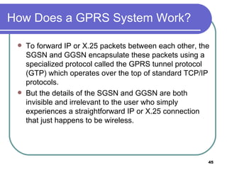
  • 45. How Does a GPRS System Work? To forward IP or X.25 packets between each other, the SGSN and GGSN encapsulate these packets using a specialized protocol called the GPRS tunnel protocol (GTP) which operates over the top of standard TCP/IP protocols. But the details of the SGSN and GGSN are both invisible and irrelevant to the user who simply experiences a straightforward IP or X.25 connection that just happens to be wireless.
  • 46. How Does a GPRS achieve high speeds? GPRS uses the same radio channel as voice calls, a channel that is 200 kHz wide This radio channel carries a raw digital radio stream of 271 kbps which for voice calls is divided into 8 separate data streams, each carrying about 34 kbps. After protocol and error correction overhead, 13 kbps is left for each voice connection or about 14 kbps for data. Circuit-switched data today uses one voice channel GPRS can combine up to 8 of these channels, and since each of these can deliver up to 14 kbps of data throughput, the net result is that users will be able to enjoy rates over 100 Kbps. The GPRS standard defines a mechanism by which a mobile station can request the amount of bandwidth it desires at the time it establishes a data session.
  • 47. GPRS quality of service
  • 48. Examples for GPRS device classes 5 4 4 12 5 2 4 10 5 1 4 8 4 2 2 5 3 2 2 3 3 1 2 2 2 1 1 1 Maximum number of slots Sending slots Receiving slots Class
  • 49. GPRS user data rates in kbit/s 171.2 149.8 128.4 107 85.6 64.2 42.8 21.4 CS-4 124.8 109.2 93.6 78 62.4 46.8 31.2 15.6 CS-3 107.2 93.8 80.4 67 53.6 40.2 26.8 13.4 CS-2 72.4 63.35 54.3 45.25 36.2 27.15 18.1 9.05 CS-1 8 slots 7 slots 6 slots 5 slots 4 slots 3 slots 2 slots 1 slot Coding scheme
  • 50. GPRS architecture and interfaces GPRS Support nodes(Routers) PDN : Packet Data Networks Servicing GSN Gateway GSN MS BSS GGSN SGSN MSC U m EIR HLR/ GR VLR PDN G b G n G i SGSN G n
  • 51. GPRS Architecture GGSN : Interfaces b/w GPRS and other Packet Data Networks(PDN) - contains routing info for GPRS - performs address conversion Tunnels data to user via encapsulation MSC is used only for signaling
  • 52. GPRS Architecture SGSN : Counterpart of MSC - supports MS via MS interface via Gb I/F - Requests user address from GPRS Register - Keeps track of individual MS location - collects billing info - access control for security
  • 53. GPRS protocol architecture apps. IP/X.25 LLC GTP MAC radio MAC radio FR RLC BSSGP IP/X.25 FR U m G b G n L1/L2 L1/L2 MS BSS SGSN GGSN UDP/TCP G i SNDCP RLC BSSGP IP IP LLC UDP/TCP SNDCP GTP Subnet Dependent Convergence Protocol(SNDCP)’ BSSGP : Base Station Subsystem GPRS FR (Frame Relay Network)
  • 54. GPRS Transmission Ref Model All data within GPRS is transferred using GPRS tunneling protocol(GTP). Can use either TCP(Reliable) or UDP(non-reliable) IP is the backbone network protocol To adopt to the different characteristics of the underlying networks, ‘Subnet Dependent Convergence Protocol(SNDCP)’ is used. LLC : logical Link Control (ensures high reliability of transfer)
  • 55. GPRS Transmission Ref Model BSSGP : Base Station Subsystem GPRS Protocol(BSSGP) – Conveys routing and QOS related info b/w BSN and SGSN. FR (Frame Relay Network) : ensures error correction RLC (Radio Link Control) : Provides Reliable Link LLC (Logical Link Control)
  • 56. DECT DECT (Digital European Cordless Telephone) standardized by ETSI (ETS 300.175-x) for cordless telephones standard describes air interface between base-station and mobile phone DECT has been renamed for international marketing reasons into „Digital Enhanced Cordless Telecommunication“ Characteristics frequency: 1880-1990 MHz channels: 120 full duplex duplex mechanism: TDD (Time Division Duplex) with 10 ms frame length multplexing scheme: FDMA with 10 carrier frequencies, TDMA with 2x 12 slots modulation: digital, Gaußian Minimum Shift Key (GMSK) power: 10 mW average (max. 250 mW) range: approx. 50 m in buildings, 300 m open space
  • 57. DECT system architecture reference model global network local network local network FT FT PT PA PT PA VDB HDB D 1 D 2 D 3 D 4 Fixed Radio Termination (FT) Portable Radio Termination(PT) Portable Applications(PA)
  • 58. DECT reference model physical layer medium access control data link control data link control network layer OSI layer 1 OSI layer 2 OSI layer 3 U-Plane C-Plane signaling, interworking application processes management close to the OSI reference model management plane over all layers several services in C(ontrol)- and U(ser)-plane
  • 59. DECT layers I Physical layer modulation/demodulation generation of the physical channel structure with a guaranteed throughput controlling of radio transmission channel assignment on request of the MAC layer detection of incoming signals sender/receiver synchronization collecting status information for the management plane MAC layer maintaining basic services, activating/deactivating physical channels multiplexing of logical channels e.g., C: signaling, I: user data, P: paging, Q: broadcast segmentation/reassembly error control/error correction
  • 60. DECT time multiplex frame slot sync A field DATA B field D field 1 frame = 10 ms 12 down slots 12 up slots 0 419 0 31 0 387 0 63 0 319 protected mode unprotected mode simplex bearer 25.6 kbit/s 32 kbit/s 420 bit + 52 µs guard time („60 bit“) in 0.4167 ms guard X field 0 3 A: network control B: user data X: transmission quality DATA 64 C 16 DATA 64 C 16 DATA 64 C 16 DATA 64 C 16
  • 61. DECT layers II Data link control layer creation and keeping up reliable connections between the mobile terminal and basestation two DLC protocols for the control plane (C-Plane) connectionless broadcast service: paging functionality Lc+LAPC protocol: in-call signaling (similar to LAPD within ISDN), adapted to the underlying MAC service
  • 62. DECT layers II several services specified for the user plane (U-Plane) null-service: offers unmodified MAC services frame relay: simple packet transmission frame switching: time-bounded packet transmission error correcting transmission: uses FEC, for delay critical, time-bounded services bandwidth adaptive transmission „ Escape“ service: for further enhancements of the standard
  • 63. DECT layers III Network layer similar to ISDN (Q.931) and GSM (04.08) offers services to request, check, reserve, control, and release resources at the basestation and mobile terminal resources necessary for a wireless connection necessary for the connection of the DECT system to the fixed network main tasks call control: setup, release, negotiation, control call independent services: call forwarding, accounting, call redirecting mobility management: identity management, authentication, management of the location register
  • 64. Enhancements of the standard Several „DECT Application Profiles“ in addition to the DECT specification GAP (Generic Access Profile) standardized by ETSI in 1997 assures interoperability between DECT equipment of different manufacturers (minimal requirements for voice communication) enhanced management capabilities through the fixed network: Cordless Terminal Mobility (CTM) DECT/GSM Interworking Profile (GIP): connection to GSM ISDN Interworking Profiles (IAP, IIP): connection to ISDN Radio Local Loop Access Profile (RAP): public telephone service CTM Access Profile (CAP): support for user mobility DECT basestation GAP DECT Common Air Interface DECT Portable Part fixed network