Lecture Notes: EEEC4340318 Instrumentation and Control Systems - Root Locus Procedure
Download as PPTX, PDF0 likes86 views

This document outlines the root locus procedure for analyzing how the closed-loop poles of a control system change with variations in the open-loop gain. It begins with examples of simple second-order systems and shows how the poles move in the complex plane as the gain increases from 0 to infinity. General principles are then described for sketching the root loci of more complex open-loop transfer functions. Key aspects are interpreting the characteristic equation geometrically in terms of distances and angles between the open-loop poles and zeros. Finally, the document proposes developing a formal root locus procedure to broadly apply this design technique in control systems.


Lecture Notes: EEEC4340318 Instrumentation and Control Systems - Root Locus Procedure
- 1. EEEC 4340318 INSTRUMENTATION AND CONTROL SYSTEMS Root Locus Procedure FACULTY OF ENGINEERING AND COMPUTER TECHNOLOGY DIPLOMA IN ELECTRICALAND ELECTRONIC ENGINEERING Ravandran Muttiah BEng (Hons) MSc MIET
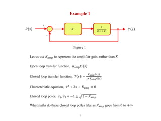
- 2. 1 Example 1 Let us use 𝐾amp to represent the amplifier gain, rather than 𝐾 Open loop transfer function, 𝐾amp 𝐺 𝑠 Closed loop transfer function, 𝑇 𝑠 = 𝐾amp 𝐺 𝑠 1+𝐾amp 𝐺 𝑠 Characteristic equation, 𝑠2 + 2𝑠 + 𝐾amp = 0 Closed loop poles, 𝑠1, 𝑠2 = −1 ± 1 − 𝐾amp What paths do these closed loop poles take as 𝐾amp goes from 0 to +∞ 𝐾𝑅 𝑠 𝑌 𝑠 1 𝑠 𝑠 + 2 + − Figure 1
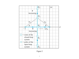
- 3. 2 Figure 2
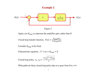
- 4. 3 Example 2 𝐾𝑅 𝑠 𝑌 𝑠 1 𝑠 𝑠 + 𝑎 + − Again, use 𝐾amp to represent the amplifier gain, rather than 𝐾 Closed loop transfer function, 𝑇 𝑠 = 𝐾amp 𝐺 𝑠 1+𝐾amp 𝐺 𝑠 Consider 𝐾amp to be fixed Characteristic equation, 𝑠2 + 𝑎𝑠 + 𝐾amp = 0 Closed loop poles, 𝑠1, 𝑠2 = −𝑎± 𝑎2−4𝐾amp 2 What paths do these closed loop poles take as 𝑎 goes from 0 to +∞ Figure 3
- 5. 4 Example 3 × × 𝑠1 𝑠2 𝑠1 𝑠1 + j 𝐾 −j 𝐾 j 𝐾 𝑠1 − j 𝐾 Figure 4
- 6. 5 What To Do In The General Case In the previous examples we exploited the simple factorization of second order polynomials. However, it would be very much useful to be able to draw the paths that the closed loop poles take as 𝐾amp increases for more general open loop systems. 𝐾𝑅 𝑠 𝑌 𝑠𝐺 𝑠 + − Figure 5
- 7. 6 Principles Of General Procedure Again, use 𝐾amp to represent the amplifier gain, rather than 𝐾 Closed loop transfer function, 𝑇 𝑠 = 𝐾amp 𝐺 𝑠 1+𝐾amp 𝐺 𝑠 = 𝑃 𝑠 𝑞 𝑠 Closed loop poles are solutions to 𝑞 𝑠 = 0 These are also solutions to 1 + 𝐾amp 𝐺 𝑠 = 0 or 𝐾amp 𝐺 𝑠 = −1 + 𝑗0 In polar form, 𝐾amp 𝐺 𝑠 ∠𝐾amp 𝐺 𝑠 = 1∠ 180° + 𝑘360° . Therefore, for an arbitrary point on the complex plane 𝑠0 to be a closed lop pole for a given value of 𝐾ampthe following equations must be satisfied. 𝐾amp 𝐺 𝑠0 = 1 and ∠𝐾amp 𝐺 𝑠0 = ∠ 180° + 𝑙360° where 𝑙 is any integer. (Note: Book uses 𝑘, but we will use 𝑙 to avoid confusion with 𝐾) We will also keep in mind that 𝑅 𝑠 and 𝑌 𝑠 and correspond to real signals. Hence, closed loop poles are either real or occur in complex conjugate pairs.
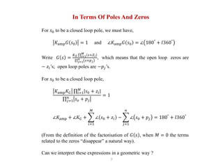
- 8. 7 In Terms Of Poles And Zeros For 𝑠0 to be a closed loop pole, we must have, 𝐾amp 𝐺 𝑠0 = 1 and ∠𝐾amp 𝐺 𝑠0 = ∠ 180° + 𝑙360° Write 𝐺 𝑠 = 𝐾 𝐺 𝑖=1 𝑀 𝑠+𝑍 𝑖 𝑗=1 𝑛 𝑠+𝑝 𝑗 , which means that the open loop zeros are − 𝑧𝑖’s; open loop poles are −𝑝𝑗’s. For 𝑠0 to be a closed loop pole, 𝐾amp 𝐾 𝐺 𝑖=1 𝑀 𝑠0 + 𝑧𝑖 𝑗=1 𝑛 𝑠 𝑜 + 𝑝𝑗 = 1 ∠𝐾amp + ∠𝐾 𝐺 + 𝑖=1 𝑀 ∠ 𝑠0 + 𝑧𝑖 − 𝑗=1 𝑛 ∠ 𝑠0 + 𝑝𝑗 = 180° + 𝑙360° (From the definition of the factorisation of 𝐺 𝑠 , when 𝑀 = 0 the terms related to the zeros “disappear” a natural way). Can we interpret these expressions in a geometric way ?
- 9. 8 Vector Difference Let 𝑢 and 𝑣 be complex numbers. Can you describe 𝑣 − 𝑢 in geometric terms ? Use the fact that 𝑣 = 𝑢 + 𝑣 − 𝑢 . That means that 𝑣 − 𝑢 is the vector from 𝑢 to 𝑣. 𝑣 − 𝑢 = 𝑙𝑒j𝜃 . That is, 𝑣 − 𝑢 is the length of the vector from 𝑢 to 𝑣. ∠ 𝑣 − 𝑢 is the angle of the vector from 𝑢 to 𝑣. In our expressions we have terms of the form, 𝑠0 + 𝑧𝑖 = 𝑠0 − −𝑧𝑖 and 𝑠0 + 𝑝𝑖 = 𝑠0 − −𝑝𝑗 Re Im 𝑢 𝑣𝑣 − 𝑢 𝑙 𝜃 Figure 6
- 10. 9 Geometric Interpretation Magnitude criterion: 𝐾amp 𝐾G 𝑖=1 𝑀 𝑠0 + 𝑧𝑖 𝑗=1 𝑛 𝑠0 + 𝑝𝑗 = 1 𝐾amp 𝐾G 𝑖=1 𝑀 distances from zeros if any of 𝐺 𝑠 to 𝑠0 𝑗=1 𝑛 distances from poles of 𝐺 𝑠 to 𝑠0 = 1 Phase criterion: ∠𝐾amp + ∠𝐾G + 𝑖=1 𝑀 ∠ 𝑠0 + 𝑝𝑗 − 𝑗=1 𝑛 ∠ 𝑠0 + 𝑝𝑗 = 180° + 𝑙360° ∠𝐾amp + ∠𝐾G + 𝑖=1 𝑀 angles from zeros if any of 𝐺 𝑠 to 𝑠0 − 𝑗=1 𝑛 angles from poles of 𝐺 𝑠 to 𝑠0 = 180° + 𝑙360°
- 11. 10 Now For The Challenge Can we build on these geometric interpretations of the equations in the simple case of amplifier gains to develop a broadly applicable approach to control system design ? The first step will be to develop a formal procedure for sketching the paths that the closed loop poles take as a design parameter (often an amplifier gain) changes. These are called the root loci. We will develop the formal procedure in a slightly more general setting than what we have seen so far.
- 12. 11 References (1) Tim Davidson, Introduction to Linear Control Systems, McMaster University, 2018.