SlideShare a Scribd company logo
MTT0060
Nanomaterials and
nanotechnologies
Lecture 12
OUTLINE
-How to get at nano scale?
-Top – down or bottom – up?
-What is bottom-up approach?
-What can we do with the help of CVD?
-Why electrodeposition?
No such thing as a “shrinking machine”
Must learn how to “Build them Small”
Ultimate Goal:
Dial in the properties
that you want by
designing and building
at the scale of nature
(i.e., the nanoscale)
Nanotubes:
– Long, cylindrical tubes of
carbon formed by a
catalytic growth process.
– Nanometer-scale drop of
molten iron is typical
catalyst.
– Can behave like a
conductive metal wire or
like a semiconductor
Quantum dots:
– Crystals containing only a few hundred
atoms
– Electrons are confined to widely
separated energy levels -> dot emits one
wavelength of light when excited
– Size of the dot determines electronic,
magnetic, and optical properties
– Used as biological markers (illuminating
sample with ultraviolet light crystals will
fluoresce at a specific wavelength)
There are two general approaches to the synthesis of
nanomaterials and the fabrication of nanostructures
Bottom-up approach
These approaches include the
miniaturization of materials
components (up to atomic level)
with further self-assembly
process leading to the formation
of nanostructures.
During self-assembly the physical
forces operating at nanoscale are
used to combine basic units into
larger stable structures.
Typical examples are quantum dot
formation during epitaxial growth
and formation of nanoparticles
from colloidal dispersion.
Top-down approach
These approaches use larger
(macroscopic) initial
structures,
which can be externally-
controlled in the processing of
nanostructures.
Typical examples are etching
through the mask, ball milling,
and application of severe plastic
deformation.
• Top-down methods
begin with a pattern generated on a larger
scale, then reduced to nanoscale.
–By nature, aren’t cheap and quick to
manufacture
- Slow and not suitable for large scale
production.
• Bottom-up methods
start with atoms or molecules and build up to
nanostructures
–Fabrication is much less expensive
Nano-scale structures and micro-scale structures are readily
formed using
top down and bottom up approaches.
Best chance for integration.
New Method : Bottom Up + Top Down
Self-assembled block copolymers + Optical lithography
€Gaseous phase methods
€Liquid phase methods
€Solid phase methods
€Biological methods
Principal: Gas – phase precursors interact
with a liquid– or solid- phase material
€ Gas state condensation
€ Chemical vapor deposition
€ Molecular beam epitaxy
€ Atomic layer deposition
€ Combustion
€ Thermolysis
€ Metal oxide vapor phase epitaxy
€ Ion implantation
The inert gas condensation
(IGC) process is one of the
most known and simplest
technique for production of
nanoparticles (in particular, Me
nanopowders)
1. A material, often a metal, is evaporated from a
heated metallic source into a chamber which has
been previously evacuated to about 10–7 torr and
backfilled with inert gas to a low-pressure.
2. The metal vapor cools through collisions with
the inert gas atoms, becomes supersaturated and
then nucleates homogeneously; the particle size is
usually in the range 1–100 nm and can be
controlled by varying the inert gas pressure.
3. Ultimately, the particles are collected and may
be compacted to produce a dense nanomaterial.
The population
distributions of
icosahedral (Ih)
decahedral (Dh) and
monocrystalline face
centered cubic (fcc)
morphologies as a
function of a size
[ K. Koga, K. Sugawara,
Surf. Sci. 529 (2003) 23]
Decahedral gold nanoparticle generated
from an inert gas aggregation
source using helium and deposited on
amorphous carbon film
[ K. Koga, K. Sugawara, Surf. Sci. 529 (2003) 23]
Icosahedral gold nanoparticles
generated from an inert gas
aggregation source using helium and
deposited on amorphous carbon film
[ K. Koga, K. Sugawara, Surf. Sci. 529 (2003)
23]
Principal: CVD involves the formation of nanomaterials
from the gas phase at elevated temperatures—
usually onto a solid substrate or catalyst.
http://upload.wikimedia.org/wikipedia/commons/9/9e/ThermalCVD.PNG
A molecular beam
epitaxy (MBE) machine
is essentially an ultra-
high-precision, ultra
clean evaporator,
combined with a set of
in-situ tools, such as
Auger electron
spectroscopy (AES)
and/or reflection high-
energy electron
diffraction (RHEED),
for characterization of
the deposited layers
during growth.
Schematic diagram of a molecular beam epitaxy thin film deposition
system (adapted from Nanoscale Science and Technology, Eds. R.W. Kelsall, I.W. Hamley, M.
Geoghegan, John Wiley&Sons Ltd, 2005).
In solid-source MBE, ultra-pure elements such
as gallium and arsenic are heated in
separate quasi-Knudsen effusion cells until they
begin to slowly evaporate.
The evaporated elements then condense on the
wafer, where they may react with each other.
In the example of gallium and arsenic, single-
crystal gallium arsenide is formed.
The term “beam” simply means that evaporated
atoms do not interact with each other or any
other vacuum chamber gases until they reach
the wafer, due to the long mean free paths of
the beams.
The substrate is rotated to ensure even growth
over its surface.
By operating mechanical shutters in front of
the cells, it is possible to control which
semiconductor or metal is deposited.
Slow but well controlled
deposition rate 1 to 300
nm per minute
Schematics of the commercial
MOCVD system
Lecture12_Various Fabrication Techniques1.pdf
1. High precision actuators
move atoms from place to
place
2. Micro tips emboss or
imprint materials
3. Electron (or ion) beams
are directly moved over a
surface
1. Chemical reactors create conditions for special growth
2. Biological agents sometimes used to help process
3. Materials are harvested for integration
Parameter Atomic Layer Deposition Chemical Vapor Deposition
Precursor
Reactivity
Highly Reactive/Self-limiting at saturation Less reactive / Can be autocatalytic
Potential
Materials
Metals, semiconductors, insulators/Wide
range
Metal oxides, semiconductors and carbon
compounds
Selectivity Highly selective Low selectivity
Surfaces Layers conform to surface topography of
substrate
Surfaces capable of activation
Layers conform according to surface
topography of substrate
Decomposition Reactants and product do not decompose Reactants can decompose at operation
temperature
Process Time Few seconds per cycle Variable
Uniformity Saturation mechanism ensures uniformity Uniformity control by process parameters
(partial pressure of reactants, flow, pressure,
temperature) – more difficult to execute
Thickness Controlled explicitly by number of reaction
cycles
Deposition rate: ~6 nm * min-1
Thickness control by process parameters –
more difficult to execute
Conditions Vacuum of inert atmosphere Lower temp.
(100 – 400˚ C)
P, T, concentration and gas flow distribution
have little effect on the process
Requires inert atmosphere and higher
temperatures (>600˚ C)
P,T, concentration and gas flow distribution
have significant effect on the process
Up-Scale Excellent Good
Lecture12_Various Fabrication Techniques1.pdf
http://www.spirecorp.com/images/spire_bio_medical/surface_tr
eatments/technology_overview/I2Schematic.gif
€ Molecular self-assembly
€ Supramolecular chemistry
€ Sol-gel processes
€ Single-crystal growth
€ Electrodeposition / electroplating
€ Anodizing
€ Molten salt solution electrolysis
€ Liquid template synthesis
€ Super-critical fluid expansion
• Spontaneous organization
of molecules into stable,
structurally
well-defined aggregates
(nanometer length scale).
• Molecules can be
transported to surfaces
through liquids to form self-
assembled monolayers
(SAMs).
Polythiophene wires
Lecture12_Various Fabrication Techniques1.pdf
Precipitating nanoparticles from a solution
of chemical compounds can be classified into
five major categories:
(1)colloidal methods;
(2)sol – gel processing;
(3) water – oil microemulsions method;
(4) hydrothermal synthesis; and
(5) polyol method.
Principal: solutions of the different ions are mixed
under controlled temperature and pressure to form
insoluble precipitates.
The sol is a name of a
colloidal solution made of
solid particles few
hundred nm in diameter,
suspended in a liquid
phase.
The gel can be
considered as a solid
macromolecule
immersed in a solvent.
+
Sol-gel process consists in the chemical
transformation of a liquid (the sol) into
a gel state and with subsequent post-
treatment and transition into solid
oxide material.
The main benefits of sol–gel processing are
the high purity and uniform nanostructure
achievable at low temperatures.
Lecture12_Various Fabrication Techniques1.pdf
Start with
precursor
Form Solution (e.g.,
hydrolysis)
Form Gel (e.g.,
dehydration)
Then form final
product
Aerogel (rapid
drying)
Thin-films
(spin/dip)
The Sol-Gel process allows to synthesize ceramic materials of high
purity and homogeneity by means of preparation techniques
different from the traditional process of fusion of oxides.
This process occurs in liquid solution of organometallic precursors
(TMOS, TEOS, Zr(IV)-Propoxide, Ti(IV)-Butoxide, etc. ), which,
by means of hydrolysis and condensation reactions, lead to the
formation of a new phase (SOL).
M-O-R + H2O M-OH + R-OH (hydrolysis)
M-OH + HO-M M-O-M + H2O (water
condensation)
M-O-R + HO-M M-O-M + R-OH (alcohol
condensation)
(M = Si, Zr, Ti)
The fundamental property of the sol-gel process is
that it is possible to generate ceramic material at a
temperature close to room temperature.
In the dip coating process the substrate is immersed into a sol
and then withdrawn with a well-defined speed under controlled
temperature and atmospheric conditions.
The sol left on substrate forms a film with thickness mainly
defined by the withdrawal speed, the solid content and the
viscosity of the liquid.
Next stage is a gelation (densification) of the layer by solvent
evaporation and finally annealing to obtain the oxide coating.
In an angle-dependent dip coating process
the coating thickness is dependant also on the
angle between the substrate and the liquid
surface, so different layer thickness can be
obtained on the top and bottom side of the
substrate.
Spin coating is used for making a
thin coating on relatively flat
substrates . The material to be
made into coating is dissolved or
dispersed into a solvent, and then
deposited onto the surface and
spun off to leave a uniform layer
for subsequent processing stages
and ultimate use.
The coating thickness depends
on the angle of inclination of
the substrate, the liquid
viscosity and the solvent
e v a p o r a t i o n r a t e .
The advantage of the flow-
coating process is that non-
planar large substrates can be
c o a t e d r a t h e r e a s i l y .
In the flow coating process the liquid coating
system is poured over the substrate to be
coated.
Icosahedral microparticles, pentagonal microtubes and whiskers obtained in
the process of copper electrodeposition [ after A.A. Vikarchuk]
The principle of electrodeposition is inducing
chemical reactions in an aqueous electrolyte
solution with the help of applied voltage, e.g. this
is the process of using electrical current to coat
an electrically conductive object with a relatively
thin layer of metal.
Electrochemically fabricated
flip-chip interconnects
Electrodeposition (ED)
is being exploited now to make
complex 3D electrical
interconnects in computer
chips. The key concept is that
electrodeposited materials
grow from the conductive
substrate outward, and the
geometry of the growth can be
controlled using an insulating
mask (so-called through mask
electrodeposition).
Nanometer-scale cuprous oxide
(colorized red) can be
electrodeposited through the
openings in the hexagonally packed
intermediate layer protein (white
regions) from the bacterium
Deinococcus radiodurans. Purified
crystalline protein sheets are first
adsorbed to a conductive substrate,
and then electrodeposition is carried
out to fill the nanometer-scale pores
in the protein.
Biological fabrication.
One way that proteins are being
used in electrochemical
nanotechnology is as masks for
through mask electrodeposition.
Proteins can self-organize into
complex structures representing
all possible two-dimensional (2D)
space groups built from chiral
molecules. Moreover, they are
readily engineered through
molecular biology, providing an
attractive foundation for
nanotechnology.
Miniature copper mask from the site of
Loma Negra on the far north coast of Peru,
ca.
200 C.E. Removal of the green copper
corrosion products reveals a bright gold
surface. The extremely thin layer of gold
was applied to the sheet copper by
electrochemical replacement plating.
[Heather Lechtman, Sci. Amer., 250(6), 56 (1984).]
Electrodeposition has three main
attributes that make it so well
suited for
nano-, bio- and microtechnologies.
• It can be used to grow functional
material through complex 3D masks.
• It can be performed near room
temperature from water-based
electrolytes.
• It can be scaled down to the
deposition of a few atoms or up to
large dimensions.

More Related Content

PPTX
Nanophysics
PPT
synthesis of nanomaterials
PPT
principles of nanomaterials and manufacturing.ppt
PPT
Unit-2 nano YYFYTFTF FYTFY YTRT6RTFJF.ppt
PPTX
Nanochemistry Basics (B.Tech / B.E. ))
PPTX
6_2020_04_11!06_48_32_AM.pptx
PPTX
Bottom-up approaches for nanosizing.pptx
PPTX
Synthesis of nanoparticles- physical,chemical and biological
Nanophysics
synthesis of nanomaterials
principles of nanomaterials and manufacturing.ppt
Unit-2 nano YYFYTFTF FYTFY YTRT6RTFJF.ppt
Nanochemistry Basics (B.Tech / B.E. ))
6_2020_04_11!06_48_32_AM.pptx
Bottom-up approaches for nanosizing.pptx
Synthesis of nanoparticles- physical,chemical and biological

Similar to Lecture12_Various Fabrication Techniques1.pdf (20)

PPTX
Synthesis of Nanomaterials
PPTX
Preparation of Nanoparticles
PDF
Nanomaterials & nanotechnology Part 5
PPTX
Synthesisofnanoparticles 130703041157-phpapp02
PPTX
Nanochemistry fb.tech chemistry 1st year sem 1/2
PDF
PHYSICS AND FUNCTIONAL MATERIAL AND DEVICES2.pdf
PPTX
Manufacturing technique of Nanomaterial's
PPTX
NANO TECHNOLOGY-UNIT-4-AP-PPT (1).pptx
PPTX
Thinfilms and nanomaterials_Modified October 2020.pptx
PDF
Techniques for synthesis of nano material
PDF
Lecture11_Synthesis-Nanomaterialsprocess.pdf
PPTX
Nanoparticles synthesis and characterization​ ​
PPTX
Synthesis of Nano Materials
PPTX
Nanochemistry
PPTX
Nano_Fabrication_Lecture3.pptx
PPTX
Thin films in nano particles
PDF
Viii. molecular electronics and nanoscience
PPTX
Solid, liquid and gas phase synthesis of nanomaterials
PDF
Nanobiotechnology.pdf by university of swabi
PDF
ETE444-lec5-micro-fabrication.pdf
Synthesis of Nanomaterials
Preparation of Nanoparticles
Nanomaterials & nanotechnology Part 5
Synthesisofnanoparticles 130703041157-phpapp02
Nanochemistry fb.tech chemistry 1st year sem 1/2
PHYSICS AND FUNCTIONAL MATERIAL AND DEVICES2.pdf
Manufacturing technique of Nanomaterial's
NANO TECHNOLOGY-UNIT-4-AP-PPT (1).pptx
Thinfilms and nanomaterials_Modified October 2020.pptx
Techniques for synthesis of nano material
Lecture11_Synthesis-Nanomaterialsprocess.pdf
Nanoparticles synthesis and characterization​ ​
Synthesis of Nano Materials
Nanochemistry
Nano_Fabrication_Lecture3.pptx
Thin films in nano particles
Viii. molecular electronics and nanoscience
Solid, liquid and gas phase synthesis of nanomaterials
Nanobiotechnology.pdf by university of swabi
ETE444-lec5-micro-fabrication.pdf
Ad

More from SelvaBabu2 (10)

PDF
PLC INTRODUCTION-Programmable Logic Controller.pdf
PPT
TQM UNIT-V.ppt TOTAL QUALITY MANAGEMENT1
PPT
TQM_TAGUCHI.ppt Total Quality Management
PDF
Unit_3_Machine Design.pdf useful for students
PDF
Unit_1_Machine Design.pdf useful for stu
PDF
DESIGN OF MACHINE ELEMENTS NOTES.PDF SHARE
PDF
surface texture parameters 3d parameters
PDF
Lecture4-Overney-NanoParticle-Synthesis.pdf
PDF
Pahl and Beitz model systematic approach to conceptual engineering
PDF
Design for Manual Assembly Lecture Rev 4.pdf
PLC INTRODUCTION-Programmable Logic Controller.pdf
TQM UNIT-V.ppt TOTAL QUALITY MANAGEMENT1
TQM_TAGUCHI.ppt Total Quality Management
Unit_3_Machine Design.pdf useful for students
Unit_1_Machine Design.pdf useful for stu
DESIGN OF MACHINE ELEMENTS NOTES.PDF SHARE
surface texture parameters 3d parameters
Lecture4-Overney-NanoParticle-Synthesis.pdf
Pahl and Beitz model systematic approach to conceptual engineering
Design for Manual Assembly Lecture Rev 4.pdf
Ad

Recently uploaded (20)

PDF
Abrasive, erosive and cavitation wear.pdf
PDF
BIO-INSPIRED HORMONAL MODULATION AND ADAPTIVE ORCHESTRATION IN S-AI-GPT
PDF
737-MAX_SRG.pdf student reference guides
PPTX
UNIT 4 Total Quality Management .pptx
PPT
INTRODUCTION -Data Warehousing and Mining-M.Tech- VTU.ppt
PPTX
communication and presentation skills 01
PPT
introduction to datamining and warehousing
PDF
Level 2 – IBM Data and AI Fundamentals (1)_v1.1.PDF
PDF
Visual Aids for Exploratory Data Analysis.pdf
PPT
A5_DistSysCh1.ppt_INTRODUCTION TO DISTRIBUTED SYSTEMS
PDF
Unit I ESSENTIAL OF DIGITAL MARKETING.pdf
PDF
PREDICTION OF DIABETES FROM ELECTRONIC HEALTH RECORDS
PPT
Occupational Health and Safety Management System
PDF
Mitigating Risks through Effective Management for Enhancing Organizational Pe...
PPTX
Safety Seminar civil to be ensured for safe working.
PDF
BIO-INSPIRED ARCHITECTURE FOR PARSIMONIOUS CONVERSATIONAL INTELLIGENCE : THE ...
PDF
R24 SURVEYING LAB MANUAL for civil enggi
PDF
SMART SIGNAL TIMING FOR URBAN INTERSECTIONS USING REAL-TIME VEHICLE DETECTI...
PDF
Exploratory_Data_Analysis_Fundamentals.pdf
PDF
Automation-in-Manufacturing-Chapter-Introduction.pdf
Abrasive, erosive and cavitation wear.pdf
BIO-INSPIRED HORMONAL MODULATION AND ADAPTIVE ORCHESTRATION IN S-AI-GPT
737-MAX_SRG.pdf student reference guides
UNIT 4 Total Quality Management .pptx
INTRODUCTION -Data Warehousing and Mining-M.Tech- VTU.ppt
communication and presentation skills 01
introduction to datamining and warehousing
Level 2 – IBM Data and AI Fundamentals (1)_v1.1.PDF
Visual Aids for Exploratory Data Analysis.pdf
A5_DistSysCh1.ppt_INTRODUCTION TO DISTRIBUTED SYSTEMS
Unit I ESSENTIAL OF DIGITAL MARKETING.pdf
PREDICTION OF DIABETES FROM ELECTRONIC HEALTH RECORDS
Occupational Health and Safety Management System
Mitigating Risks through Effective Management for Enhancing Organizational Pe...
Safety Seminar civil to be ensured for safe working.
BIO-INSPIRED ARCHITECTURE FOR PARSIMONIOUS CONVERSATIONAL INTELLIGENCE : THE ...
R24 SURVEYING LAB MANUAL for civil enggi
SMART SIGNAL TIMING FOR URBAN INTERSECTIONS USING REAL-TIME VEHICLE DETECTI...
Exploratory_Data_Analysis_Fundamentals.pdf
Automation-in-Manufacturing-Chapter-Introduction.pdf

Lecture12_Various Fabrication Techniques1.pdf

  • 1. MTT0060 Nanomaterials and nanotechnologies Lecture 12 OUTLINE -How to get at nano scale? -Top – down or bottom – up? -What is bottom-up approach? -What can we do with the help of CVD? -Why electrodeposition?
  • 2. No such thing as a “shrinking machine” Must learn how to “Build them Small” Ultimate Goal: Dial in the properties that you want by designing and building at the scale of nature (i.e., the nanoscale)
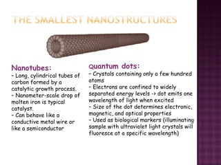
  • 3. Nanotubes: – Long, cylindrical tubes of carbon formed by a catalytic growth process. – Nanometer-scale drop of molten iron is typical catalyst. – Can behave like a conductive metal wire or like a semiconductor Quantum dots: – Crystals containing only a few hundred atoms – Electrons are confined to widely separated energy levels -> dot emits one wavelength of light when excited – Size of the dot determines electronic, magnetic, and optical properties – Used as biological markers (illuminating sample with ultraviolet light crystals will fluoresce at a specific wavelength)
  • 4. There are two general approaches to the synthesis of nanomaterials and the fabrication of nanostructures Bottom-up approach These approaches include the miniaturization of materials components (up to atomic level) with further self-assembly process leading to the formation of nanostructures. During self-assembly the physical forces operating at nanoscale are used to combine basic units into larger stable structures. Typical examples are quantum dot formation during epitaxial growth and formation of nanoparticles from colloidal dispersion. Top-down approach These approaches use larger (macroscopic) initial structures, which can be externally- controlled in the processing of nanostructures. Typical examples are etching through the mask, ball milling, and application of severe plastic deformation.
  • 5. • Top-down methods begin with a pattern generated on a larger scale, then reduced to nanoscale. –By nature, aren’t cheap and quick to manufacture - Slow and not suitable for large scale production. • Bottom-up methods start with atoms or molecules and build up to nanostructures –Fabrication is much less expensive
  • 6. Nano-scale structures and micro-scale structures are readily formed using top down and bottom up approaches. Best chance for integration. New Method : Bottom Up + Top Down Self-assembled block copolymers + Optical lithography
  • 7. €Gaseous phase methods €Liquid phase methods €Solid phase methods €Biological methods
  • 8. Principal: Gas – phase precursors interact with a liquid– or solid- phase material € Gas state condensation € Chemical vapor deposition € Molecular beam epitaxy € Atomic layer deposition € Combustion € Thermolysis € Metal oxide vapor phase epitaxy € Ion implantation
  • 9. The inert gas condensation (IGC) process is one of the most known and simplest technique for production of nanoparticles (in particular, Me nanopowders)
  • 10. 1. A material, often a metal, is evaporated from a heated metallic source into a chamber which has been previously evacuated to about 10–7 torr and backfilled with inert gas to a low-pressure. 2. The metal vapor cools through collisions with the inert gas atoms, becomes supersaturated and then nucleates homogeneously; the particle size is usually in the range 1–100 nm and can be controlled by varying the inert gas pressure. 3. Ultimately, the particles are collected and may be compacted to produce a dense nanomaterial.
  • 11. The population distributions of icosahedral (Ih) decahedral (Dh) and monocrystalline face centered cubic (fcc) morphologies as a function of a size [ K. Koga, K. Sugawara, Surf. Sci. 529 (2003) 23]
  • 12. Decahedral gold nanoparticle generated from an inert gas aggregation source using helium and deposited on amorphous carbon film [ K. Koga, K. Sugawara, Surf. Sci. 529 (2003) 23] Icosahedral gold nanoparticles generated from an inert gas aggregation source using helium and deposited on amorphous carbon film [ K. Koga, K. Sugawara, Surf. Sci. 529 (2003) 23]
  • 13. Principal: CVD involves the formation of nanomaterials from the gas phase at elevated temperatures— usually onto a solid substrate or catalyst. http://upload.wikimedia.org/wikipedia/commons/9/9e/ThermalCVD.PNG
  • 14. A molecular beam epitaxy (MBE) machine is essentially an ultra- high-precision, ultra clean evaporator, combined with a set of in-situ tools, such as Auger electron spectroscopy (AES) and/or reflection high- energy electron diffraction (RHEED), for characterization of the deposited layers during growth.
  • 15. Schematic diagram of a molecular beam epitaxy thin film deposition system (adapted from Nanoscale Science and Technology, Eds. R.W. Kelsall, I.W. Hamley, M. Geoghegan, John Wiley&Sons Ltd, 2005).
  • 16. In solid-source MBE, ultra-pure elements such as gallium and arsenic are heated in separate quasi-Knudsen effusion cells until they begin to slowly evaporate. The evaporated elements then condense on the wafer, where they may react with each other. In the example of gallium and arsenic, single- crystal gallium arsenide is formed. The term “beam” simply means that evaporated atoms do not interact with each other or any other vacuum chamber gases until they reach the wafer, due to the long mean free paths of the beams. The substrate is rotated to ensure even growth over its surface. By operating mechanical shutters in front of the cells, it is possible to control which semiconductor or metal is deposited.
  • 17. Slow but well controlled deposition rate 1 to 300 nm per minute
  • 18. Schematics of the commercial MOCVD system
  • 20. 1. High precision actuators move atoms from place to place 2. Micro tips emboss or imprint materials 3. Electron (or ion) beams are directly moved over a surface 1. Chemical reactors create conditions for special growth 2. Biological agents sometimes used to help process 3. Materials are harvested for integration
  • 21. Parameter Atomic Layer Deposition Chemical Vapor Deposition Precursor Reactivity Highly Reactive/Self-limiting at saturation Less reactive / Can be autocatalytic Potential Materials Metals, semiconductors, insulators/Wide range Metal oxides, semiconductors and carbon compounds Selectivity Highly selective Low selectivity Surfaces Layers conform to surface topography of substrate Surfaces capable of activation Layers conform according to surface topography of substrate Decomposition Reactants and product do not decompose Reactants can decompose at operation temperature Process Time Few seconds per cycle Variable Uniformity Saturation mechanism ensures uniformity Uniformity control by process parameters (partial pressure of reactants, flow, pressure, temperature) – more difficult to execute Thickness Controlled explicitly by number of reaction cycles Deposition rate: ~6 nm * min-1 Thickness control by process parameters – more difficult to execute Conditions Vacuum of inert atmosphere Lower temp. (100 – 400˚ C) P, T, concentration and gas flow distribution have little effect on the process Requires inert atmosphere and higher temperatures (>600˚ C) P,T, concentration and gas flow distribution have significant effect on the process Up-Scale Excellent Good
  • 24. € Molecular self-assembly € Supramolecular chemistry € Sol-gel processes € Single-crystal growth € Electrodeposition / electroplating € Anodizing € Molten salt solution electrolysis € Liquid template synthesis € Super-critical fluid expansion
  • 25. • Spontaneous organization of molecules into stable, structurally well-defined aggregates (nanometer length scale). • Molecules can be transported to surfaces through liquids to form self- assembled monolayers (SAMs). Polythiophene wires
  • 27. Precipitating nanoparticles from a solution of chemical compounds can be classified into five major categories: (1)colloidal methods; (2)sol – gel processing; (3) water – oil microemulsions method; (4) hydrothermal synthesis; and (5) polyol method.
  • 28. Principal: solutions of the different ions are mixed under controlled temperature and pressure to form insoluble precipitates.
  • 29. The sol is a name of a colloidal solution made of solid particles few hundred nm in diameter, suspended in a liquid phase. The gel can be considered as a solid macromolecule immersed in a solvent. + Sol-gel process consists in the chemical transformation of a liquid (the sol) into a gel state and with subsequent post- treatment and transition into solid oxide material. The main benefits of sol–gel processing are the high purity and uniform nanostructure achievable at low temperatures.
  • 31. Start with precursor Form Solution (e.g., hydrolysis) Form Gel (e.g., dehydration) Then form final product Aerogel (rapid drying) Thin-films (spin/dip)
  • 32. The Sol-Gel process allows to synthesize ceramic materials of high purity and homogeneity by means of preparation techniques different from the traditional process of fusion of oxides. This process occurs in liquid solution of organometallic precursors (TMOS, TEOS, Zr(IV)-Propoxide, Ti(IV)-Butoxide, etc. ), which, by means of hydrolysis and condensation reactions, lead to the formation of a new phase (SOL). M-O-R + H2O M-OH + R-OH (hydrolysis) M-OH + HO-M M-O-M + H2O (water condensation) M-O-R + HO-M M-O-M + R-OH (alcohol condensation) (M = Si, Zr, Ti)
  • 33. The fundamental property of the sol-gel process is that it is possible to generate ceramic material at a temperature close to room temperature.
  • 34. In the dip coating process the substrate is immersed into a sol and then withdrawn with a well-defined speed under controlled temperature and atmospheric conditions. The sol left on substrate forms a film with thickness mainly defined by the withdrawal speed, the solid content and the viscosity of the liquid. Next stage is a gelation (densification) of the layer by solvent evaporation and finally annealing to obtain the oxide coating.
  • 35. In an angle-dependent dip coating process the coating thickness is dependant also on the angle between the substrate and the liquid surface, so different layer thickness can be obtained on the top and bottom side of the substrate. Spin coating is used for making a thin coating on relatively flat substrates . The material to be made into coating is dissolved or dispersed into a solvent, and then deposited onto the surface and spun off to leave a uniform layer for subsequent processing stages and ultimate use.
  • 36. The coating thickness depends on the angle of inclination of the substrate, the liquid viscosity and the solvent e v a p o r a t i o n r a t e . The advantage of the flow- coating process is that non- planar large substrates can be c o a t e d r a t h e r e a s i l y . In the flow coating process the liquid coating system is poured over the substrate to be coated.
  • 37. Icosahedral microparticles, pentagonal microtubes and whiskers obtained in the process of copper electrodeposition [ after A.A. Vikarchuk] The principle of electrodeposition is inducing chemical reactions in an aqueous electrolyte solution with the help of applied voltage, e.g. this is the process of using electrical current to coat an electrically conductive object with a relatively thin layer of metal.
  • 38. Electrochemically fabricated flip-chip interconnects Electrodeposition (ED) is being exploited now to make complex 3D electrical interconnects in computer chips. The key concept is that electrodeposited materials grow from the conductive substrate outward, and the geometry of the growth can be controlled using an insulating mask (so-called through mask electrodeposition).
  • 39. Nanometer-scale cuprous oxide (colorized red) can be electrodeposited through the openings in the hexagonally packed intermediate layer protein (white regions) from the bacterium Deinococcus radiodurans. Purified crystalline protein sheets are first adsorbed to a conductive substrate, and then electrodeposition is carried out to fill the nanometer-scale pores in the protein. Biological fabrication. One way that proteins are being used in electrochemical nanotechnology is as masks for through mask electrodeposition. Proteins can self-organize into complex structures representing all possible two-dimensional (2D) space groups built from chiral molecules. Moreover, they are readily engineered through molecular biology, providing an attractive foundation for nanotechnology.
  • 40. Miniature copper mask from the site of Loma Negra on the far north coast of Peru, ca. 200 C.E. Removal of the green copper corrosion products reveals a bright gold surface. The extremely thin layer of gold was applied to the sheet copper by electrochemical replacement plating. [Heather Lechtman, Sci. Amer., 250(6), 56 (1984).] Electrodeposition has three main attributes that make it so well suited for nano-, bio- and microtechnologies. • It can be used to grow functional material through complex 3D masks. • It can be performed near room temperature from water-based electrolytes. • It can be scaled down to the deposition of a few atoms or up to large dimensions.