


![ΔL = ΔL1 + ΔL2 + ΔL3
ΔL =
1
𝐸
[
P1
L1
𝐴1
−
P2
L2
𝐴2
+
P3
L3
𝐴3
]
E = 205 × 109
Pa = 205 × 109 𝑁
𝑚2 =
205×109 𝑁
1000𝑚𝑚 2
= 205 × 103 𝑁
𝑚𝑚2
ΔL =
1
205×103 [
50000×150
176.71
−
250000 ×200
706.86
+
80000 ×250
314.16
] = ≈ 0.173 mm
Problem: A circular bar (E = 205 GPa) has three segments, as shown in figure.
Find: (a) Total elongation in bar. (b) Length of middle segment to have zero
elongation of bar. (c) Dia of last segment to have zero elongation of bar.
Solution:
(a) Total Elongation in the Bar:
𝐴 =
𝜋
4
𝑑 2
𝐴1 = 176.71 𝑚𝑚2
𝐴2 = 706.86 𝑚𝑚2
𝐴3 = 314.16 𝑚𝑚2
Net Elongation =Sum of Individual Elongations](https://image.slidesharecdn.com/lecture-3-1-230128061630-84adee53/85/Lecture-3-1-pptx-20-320.jpg)
![Putting ΔL = 0
0 =
1
205×103 [
50000×150
176.71
−
250000 ×L2
706.86
+
80000 ×250
314.16
]
L2 = 300 mm
(b) Length of Middle Segment (L2) at Zero Elongation of Bar:
Putting ΔL = 0
1
205×103 [
50000×150
176.71
− (
250000 ×200
706.86
)+(
80000 ×250
𝜋
4
𝑑3
2 )] = 0
𝑑3 = 30 mm
(c) Dia of Last Segment (D3) to have Zero Elongation of Bar:](https://image.slidesharecdn.com/lecture-3-1-230128061630-84adee53/85/Lecture-3-1-pptx-21-320.jpg)


![As bar remains horizontal than deformation in brass and steel
will also be same i.e. (means 𝜟Lb = 𝜟Ls).
Problem: Three equally spaced circular rods in same vertical plane supports a rigid bar
AB. Two outer rods are of brass each 600 mm long and 25mm diameter. The central
steel rod is of steel that is 800mm long and 30mm diameter. Determine forces in the
bars due to applied load of 120 KN through the mid point of the bar. Bar remains
horizontal after application of load.Take Es/EB = 2
Solution:
Put Pb into above equation
2(
25
54
Ps) + Ps = 120
⇨ Ps =
𝟏𝟐𝟎×𝟓𝟒
𝟏𝟎𝟒
= 𝟔𝟐. 𝟑 𝒌𝑵
PbLb
𝐴𝑏𝐸𝑏
=
PsLs
𝐴𝑠𝐸𝑠
𝐏𝐛 = Ps [
Ls
Lb
×
𝐴𝑏
𝐴𝑠
×
𝐸𝑏
𝐸𝑠
] = Ps [
800
600
×
𝜋
4
25 2
𝜋
4
30 2
×
1
2
]
FBD
⇨ 𝐏𝐛 =
𝟐𝟓
𝟓𝟒
𝐏𝐬
⇨ 2Pb+ Ps = 120
+↑ ∑𝐹𝑦 = 0 ⇨ Pb+ Ps + Pb – 120 = 0
⇨ Pb = 𝟐𝟖. 𝟖 𝒌𝑵](https://image.slidesharecdn.com/lecture-3-1-230128061630-84adee53/85/Lecture-3-1-pptx-24-320.jpg)
![Problem: Circular bar is loaded as shown. Find (a) Reaction at lower support. (b)
Stresses in bars. Take E = 205 Gpa (205×103 N/mm2)
Solution:
From the figure
ΔLnet = ΔL1 + ΔL2 =0.8mm
From equilibrium eq
R1 + R2 – 40 = 0 ⇨ R1 = 40kN – R2
As we know
ΔL1 – ΔL2 = 0.8 𝑚𝑚
Given: A1 = 80 mm2 , A2 = 160 mm2
1
205×103 [
40000−R2
80 𝑚𝑚2 −
2400 ×R2
160 𝑚𝑚2 ] = 0.8 mm ⇨ R2 = 14533.3 N
P1
L1
𝐴1
𝐸
–
P2
L2
𝐴2
𝐸
= 0.8 mm
⇨ R1 = 25466.7 N](https://image.slidesharecdn.com/lecture-3-1-230128061630-84adee53/85/Lecture-3-1-pptx-25-320.jpg)


Lecture-3-1.pptx
- 1. Lecture-3 Mechanics of Materials-I Waqas Asghar waqas.asghar@uettaxila.edu.pk Lecturer, Mechanical Dept. UET Taxila
- 4. SAINT-VENANT’S PRINCIPLE • The principle was first noticed by the French scientist Barré de Saint-Venant in 1855. • Notice the stress distribution acting at sections a–a, b–b, and c–c • At c–c , stress distribution is uniform & is located at a distance ≥ width of bar. • At b–b , stress distribution is non-uniform. • At a–a , stress distribution is highly non-uniform. In a loaded material, “if the cross section is taken away from the point of load application or support, stress & strain distribution on that cross-section will be independent of applied load”.
- 5. SAINT-VENANT’S PRINCIPLE If we convert the point load to uniformly distributed load, resultant stress and strain distribution will become uniform.
- 6. • A bar having variable cross-sectional area along its length L, is shown in figure. • Bar is subjected to concentrated loads at its end. • 𝛿 =? = Relative displacement of one end w.r.t other, caused by loading. • Neglect the localized deformation caused at the point of concentrated loading and where the cross section changes suddenly, • Take an element of length dx, area A(x) from bar, at any position x. • Stress and strain in element will be given by: 𝝈 = 𝑷(𝒙) 𝑨(𝒙) and 𝜺 = d𝜹 𝒅𝒙 Elastic Deformation Of Axially Loaded Member
- 7. Within elastic limit, Hooke’s law is applicable; i.e. 𝝈 = 𝑬. 𝜺 Putting the values of 𝝈 & 𝜺 from previous slide, Hooke’s law becomes 𝑷(𝒙) 𝑨(𝒙) = 𝑬. d𝜹 𝒅𝒙 d𝜹 = 𝑷 𝒙 dx 𝑨 𝒙 𝑬 For entire length of bar 𝜹 = 𝟎 𝑳 𝑷 𝒙 dx 𝑨 𝒙 𝑬 where 𝜹 = displacement of one point on the bar relative to the other point L = original length of bar P(x) = Internal axial force at the section (in terms of x), determined by method of sections A(x) = cross-sectional area of the bar, expressed as a function of x E = modulus of elasticity for the material
- 8. 𝜹 = 𝑷𝑳 𝑨𝑬 Elastic Deformation of Bar Subjected To Constant Axial Force, Having Constant Cross –Sectional Area & Constant ‘E’ 𝜹 = ∑ 𝑷𝑳 𝑨𝑬 Elastic Deformation of Bar Subjected To Several Different Axial Forces, Having Variable Cross –Sectional Areas & Variable ‘E’
- 9. Sign Convention Force P and displacement 𝛿 will be +ve if they cause tension or elongation and vice versa.
- 10. Example 4.1: A-36 steel bar ( E=29× 103 𝑘𝑠𝑖) is made from two segments having cross-sectional areas of AAB = 1 in2 and ABD = 2 in2. Find 𝛿𝐴 the vertical displacement (𝜹) of end A and the displacement (𝜹) of B relative to C. Solution: Find internal force in each member. Due to the application of variable external loadings, the internal axial forces in regions AB, BC, and CD will all be different & can be obtained by applying method of sections . Section AB: +↑ ∑𝑃𝑦 = 0 15 kip – PAB = 0 PAB = 15 kip (T)
- 11. Section AC: +↑ ∑𝑃𝑦 = 0 15 – (4 ×2 ) – PBC = 0 PBC = 7 kip (T) Section AD: +↑ ∑𝑃𝑦 = 0 15 – (4×2 ) – (8×2) – PCD = 0 PCD = – 9 kip (T) Displacement of A relative to the fixed support D: +ve sign shows elongation, so the displacement at A is upward.
- 12. Displacement of B relative to C: +ve sign shows elongation, as B moves away from C.
- 13. Example 4.3: Rigid beam AB rests on the two short posts. Post AC is made of steel having 20 mm dia and Est = 200 G. Post BD is made of aluminum having 40 mm dia and Eal = 70 G. Determine the displacement (𝜹) of point F. Solution: Find the internal forces, by using force and moment equilibrium equations, as: +↑ ∑𝐹𝑦 = 0 − 90 + FA + FB = 0 FA + FB = 90 kN +↺ ∑𝑀𝐴 = 0 − 90(200) + (600)FB = 0 FB = 30 kN Putting FB into above eq, we have : FA = 60 kN Support Reactions at Point A & B
- 14. 𝜹 of point F can’t be found directly. For this purpose, initially we have to found the deflection of point A & B. Post AC: Post BD: Compressive forces acting on post AC & BD are equal in magnitude to the internal forces, calculated previously (FA = 60 kN, FA = 30 kN) but will act in opposite direction to maintain equilibrium. Displacement of Point A & B Compressive Forces Acting on Post AC & BD
- 15. Now from trigonometry taking proportion of sides of two blue shaded triangles Δ𝑧𝑛𝑦 𝑎𝑛𝑑 Δ𝑧𝑚𝑥 𝑧𝑛 𝑧𝑚 = 𝑛𝑦 𝑚𝑥 ⟹ 400 𝑚𝑚 600 𝑚𝑚 = 𝑛𝑦 0.184 𝐧𝐲 = 𝟎. 𝟏𝟐𝟐𝟕 𝒎𝒎 Diagram Showing Displacements of Points A, B & F We have already calculated the 𝜹𝑨 & 𝜹𝑩. So From figure 𝜹𝑨 = 𝜹𝑩 +mx 0.286 𝑚𝑚 = 0.102 𝑚𝑚 + mx 𝒎𝒙 = 𝟎. 𝟏𝟖𝟒 𝒎𝒎 Displacement of Point F As, 𝜹𝑭 = 𝜹𝑩 +ny 𝜹𝑭 = 0.102 𝑚𝑚 + 0.1227 mm 𝜹𝑭 = 𝟎. 𝟐𝟐𝟓 𝒎𝒎 ↓
- 16. The Principle of Superposition In a linearly elastic structure, combined effect of several loads acting simultaneously on a member is equal to the summation of the loads acting separately. • This Principle simplifies the stress (𝝈), displacement (𝜹) or deflection problems having complicated or multiple loadings. • This is done by breaking the member down as many times as necessary for each force acting on it. • Once all the stresses or deflections are found, they can then be added to get a final answer. • Necessary conditions required to apply principle of superposition are: The loading must be linearly related to the stress or displacement, that is to be determined. OR Hooke’s law remains applicable. The loading must not significantly change the original geometry of the member.
- 18. Forces in all segment are of tensile nature Start simplifying from R.H.S By Principle of superposition Problem: A steel bar of 25 mm dia, is acted upon by forces as shown in figure. What is the total elongation of bar when E = 190 GPa. Solution: Net Elongation = Sum of Individual Elongations ΔL = ΔL1 + ΔL2 + ΔL3 As E = 𝜎 𝜀 = P A Δ𝐿 𝐿 = 𝑃𝐿 𝐴∆𝐿 Elongation or Extension or Deformation of whole bar, ΔL = PL 𝐴𝐸 ΔL = P1 L1 𝐴𝐸 + P2 L2 𝐴𝐸 + P3 L3 𝐴𝐸 = 1 𝐴𝐸 P1L1+ P2L2 + P3L3
- 19. A = 𝜋 4 0.025 2 = 4.908 × 10 _4 m2 ΔL = 1 𝐴𝐸 P1L1+ P2L2 + P3L3 ΔL = 1 4.908 × 10⁻⁴ 190 ×109 (60000 × 2)+(80000 × 1)+(50000 × 3) = 3.75 × 10 _3 m = 3.75 mm Elongation of whole bar, 𝜟L 𝑨 = 𝝅 𝟒 𝒅 𝟐
- 20. ΔL = ΔL1 + ΔL2 + ΔL3 ΔL = 1 𝐸 [ P1 L1 𝐴1 − P2 L2 𝐴2 + P3 L3 𝐴3 ] E = 205 × 109 Pa = 205 × 109 𝑁 𝑚2 = 205×109 𝑁 1000𝑚𝑚 2 = 205 × 103 𝑁 𝑚𝑚2 ΔL = 1 205×103 [ 50000×150 176.71 − 250000 ×200 706.86 + 80000 ×250 314.16 ] = ≈ 0.173 mm Problem: A circular bar (E = 205 GPa) has three segments, as shown in figure. Find: (a) Total elongation in bar. (b) Length of middle segment to have zero elongation of bar. (c) Dia of last segment to have zero elongation of bar. Solution: (a) Total Elongation in the Bar: 𝐴 = 𝜋 4 𝑑 2 𝐴1 = 176.71 𝑚𝑚2 𝐴2 = 706.86 𝑚𝑚2 𝐴3 = 314.16 𝑚𝑚2 Net Elongation =Sum of Individual Elongations
- 21. Putting ΔL = 0 0 = 1 205×103 [ 50000×150 176.71 − 250000 ×L2 706.86 + 80000 ×250 314.16 ] L2 = 300 mm (b) Length of Middle Segment (L2) at Zero Elongation of Bar: Putting ΔL = 0 1 205×103 [ 50000×150 176.71 − ( 250000 ×200 706.86 )+( 80000 ×250 𝜋 4 𝑑3 2 )] = 0 𝑑3 = 30 mm (c) Dia of Last Segment (D3) to have Zero Elongation of Bar:
- 22. Statically Indeterminate Systems The systems in which equilibrium equations are not sufficient to find all reaction on a member. • For this purpose, deformation equation of material (ΔL = PL 𝐴𝐸 ) is also taken into account. • Statically indeterminate systems may consist of ≥ 2 members or of different materials • Example: Equilibrium equation of bar shown is given below: Simple Bar Free Body Diagram +↑ 𝑭 = 𝟎, ⇨ 𝑭𝑨 +𝑭𝑩 − 𝑷 = 𝟎
- 23. Simple Bar Free Body Diagram Kinematic or Compatibility condition. • Additional equation required for the solution of statically indeterminate systems, is referred as Compatibility condition. • In Compatibility condition, it is necessary to consider how points on the bar displace w.r.t. each other • In compatibility condition of the shown bar, displacement of one end of the bar w.r.t other end becomes zero ( 𝜹𝑨 𝑩 = 𝟎), since the end supports are fixed. • Hence, the compatibility condition becomes:
- 24. As bar remains horizontal than deformation in brass and steel will also be same i.e. (means 𝜟Lb = 𝜟Ls). Problem: Three equally spaced circular rods in same vertical plane supports a rigid bar AB. Two outer rods are of brass each 600 mm long and 25mm diameter. The central steel rod is of steel that is 800mm long and 30mm diameter. Determine forces in the bars due to applied load of 120 KN through the mid point of the bar. Bar remains horizontal after application of load.Take Es/EB = 2 Solution: Put Pb into above equation 2( 25 54 Ps) + Ps = 120 ⇨ Ps = 𝟏𝟐𝟎×𝟓𝟒 𝟏𝟎𝟒 = 𝟔𝟐. 𝟑 𝒌𝑵 PbLb 𝐴𝑏𝐸𝑏 = PsLs 𝐴𝑠𝐸𝑠 𝐏𝐛 = Ps [ Ls Lb × 𝐴𝑏 𝐴𝑠 × 𝐸𝑏 𝐸𝑠 ] = Ps [ 800 600 × 𝜋 4 25 2 𝜋 4 30 2 × 1 2 ] FBD ⇨ 𝐏𝐛 = 𝟐𝟓 𝟓𝟒 𝐏𝐬 ⇨ 2Pb+ Ps = 120 +↑ ∑𝐹𝑦 = 0 ⇨ Pb+ Ps + Pb – 120 = 0 ⇨ Pb = 𝟐𝟖. 𝟖 𝒌𝑵
- 25. Problem: Circular bar is loaded as shown. Find (a) Reaction at lower support. (b) Stresses in bars. Take E = 205 Gpa (205×103 N/mm2) Solution: From the figure ΔLnet = ΔL1 + ΔL2 =0.8mm From equilibrium eq R1 + R2 – 40 = 0 ⇨ R1 = 40kN – R2 As we know ΔL1 – ΔL2 = 0.8 𝑚𝑚 Given: A1 = 80 mm2 , A2 = 160 mm2 1 205×103 [ 40000−R2 80 𝑚𝑚2 − 2400 ×R2 160 𝑚𝑚2 ] = 0.8 mm ⇨ R2 = 14533.3 N P1 L1 𝐴1 𝐸 – P2 L2 𝐴2 𝐸 = 0.8 mm ⇨ R1 = 25466.7 N
- 26. (b) For stresses 𝜎1 = 𝑃1 𝐴1 = 𝑅1 𝐴1 = 25466.67 80 𝝈𝟏 = 318.3 N/mm2 𝜎2 = 𝑃2 𝐴2 = 𝑅2 𝐴2 = 1453.3 160 𝝈𝟐= 90.83 N/mm2
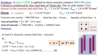
- 27. Problem: A load of 2MN is applied on short concrete column ( 500×500 )mm. Column is reinforced by four steel bars of 10mm dia. One in each corner. Find stresses in the concrete and steel bars. Est = 2.1×10⁵ N/mm2, Econ = 1.4 ×10⁴ N/mm2 Solution: P = 2×10⁶ N Area of steel bar = 𝜋 4 × 102 = 25 𝜋 mm2, Est = 2.1×10⁵ N/mm2 Econ = 1.4 ×10⁴ N/mm2 Steel bars dia = 10 mm, Quantity of Steel bars = 4 Concrete cross section = 500×500 mm, Given: Area of concrete = ( 500×500 ) – 4 (25𝜋) = 249685.8 mm2 As load P is shared by column (Steel bar + concrete) So, P = 4Psteel + Pconcrete 2×106 = 4 (𝜎s × 𝐴s) + (𝜎c × 𝐴c) 2×106 = 4 (𝜎s × 25𝜋) + (𝜎c ×249685.8) ………….. (1) ⇨ 𝝈 = 𝑷 𝑨 or P = 𝝈A
- 28. Compression in any steel bar = Compression in concrete bar 𝑃s Ls 𝐴𝑠 𝐸𝑠 = 𝑃c Lc 𝐴𝑐 𝐸𝑐 𝜎s Ls 𝐸𝑠 = 𝜎c Lc 𝐸𝑐 𝜎s 𝜎c = 𝐸𝑠 𝐸𝑐 𝜎s = 𝐸𝑠 𝜎c 𝐸𝑐 = 2.1×10⁵ 1.4×10⁴ 𝜎c 𝜎s = 15 𝜎c …….(2) Putting Equation 2 in equation 1 ∴ 𝐋𝐬 = 𝐋𝐜 ⇨ 𝝈𝐬 = 117.92 N/mm2 ⇨ 𝝈𝐜 = 7.86 N/mm2
- 29. Problem: Two vertical rods (steel and copper) each are rigidly fixed at the top and 50 cm apart. Dia and lengths of each rod are 2cm and 4m respectively. A cross bar fixed to the rods at the lower ends carries a load of 5000N such that the cross bar remains horizontal even after loading. Find the stress in each rod and the position of the load on the bar. E for steel = 2×10⁵ N/mm2 and E for Copper = 1×10⁵ N/mm2 Solution: Given: (a) As bar remains horizontal, so Extension in steel = Extension copper ∆ Lsteel = ∆Lcu 𝑃s Ls 𝐴𝑠 𝐸𝑠 = 𝑃c Lc 𝐴𝑐 𝐸𝑐 𝜎s Ls 𝐸𝑠 = 𝜎c Lc 𝐸𝑐 ds = dc = 2 cm, , Ls = Lc = 4 cm Esteel = 2×10⁵ N/mm2 , ECopper = 1×10⁵ N/mm2 ∴ 𝐋𝐬 = 𝐋𝐜 ⇨ 𝝈𝐬 = 𝑬𝒔 𝝈𝐜 𝑬𝒄 ⇨ 𝜎s 𝜎c = 𝐸𝑠 𝐸𝑐 By putting values of Es & Ec 𝜎s = 2 𝜎c ….(1)
- 30. Taking +↑ ∑𝐹𝑦 = 0 ⇨ Ps + Pc – 5000 = 0 Ps + Pc = 5000 𝜎𝑠 As + 𝜎c Ac = 5000 (𝜎𝑠 + 𝜎c)A = 5000 𝜎𝑠 + 𝜎c = 15.92 …..(2) By solving eq (1) and eq (2) ⇨ 𝝈 = 𝑷 𝑨 or P = 𝝈A ∴ 𝑨𝒔 𝒅𝐬 = 𝒅𝐜 , So 𝐀𝐬 = 𝐀𝐜 𝝈𝐬 = 10.61 N/mm2 𝝈𝐬 = 5.3 N/mm2 (b) Position of the load on the bar. Also, +↺ ∑𝑀𝐵 = 0 – Ps (500mm) + 5000x = 0 x = Ps 10 = 𝜎𝑠 As 10 = 10.61× 𝜋 4 ×(20)2 10 = 333.3 mm
- 31. 31 Practice Questions of Ch. # 4 (Hibbeler 8th ed.) • Problems = 4- 31, 35, 38, 39, 41, 42, 44, 45, 46, 62
- 32. 4.31,35,38,39,41,42,44,45,46,62 Numerical from Hibler 4.65,69,70,71,72,73,75,77,78,79,84,85,86 Thermal Stresses
- 33. FORCE METHOD OF ANALYSIS FOR AXIALLY LOADED MEMBERS Statically indeterminate problems can be solved by writing the compatibility equation using the principle of superposition. Take the pt. B and temporarily remove its effect on bar • P causes B to be displaced downward by an amount 𝛿𝑝 • reaction must displace end B of the bar upward by an amount 𝛿𝐵 So net displacement occurs at B = 0. So compatibility equation for displacements at point B is 0 = 𝛿𝑝 - 𝛿𝐵
- 34. Thermal Stresses Case-I (Free Expansion) • Temperature increases from t1 to t2 T = t2 - t1 ∆𝐿 = α T L Where α = linear coefficient of thermal expansion • If material is allowed to expand freely no thermal stress is induced Case-II (No Free Expansion) T = Rise in temperature Support are preventing the expansion Strain prevented = ∆𝑙 = α T L Strain = 𝐸𝑥𝑛𝑡𝑒𝑛𝑠𝑖𝑜𝑛 𝑝𝑟𝑒𝑣𝑒𝑛𝑡𝑒𝑑 𝑂𝑟𝑖𝑔𝑛𝑎𝑙 𝑙𝑒𝑛𝑔𝑡ℎ 𝜀 = αT L 𝐿 𝜀 = αT Thermal or compressive strain From Hook’s law E = σ 𝜀 𝜀 = σ 𝐸 αT = σ 𝐸 σ = EαT Thermal stress compressive nature
- 35. If temperature decreases bar will be contract. So strain and stress developed will be tensile on nature. ∆𝐿 = α T L In case of free expansion 𝜀 = αT Thermal or compressive stress No allowance for expansion σ = EαT Thermal stress is present When allowance for expansion is present 𝜀 = αT L − ∆𝑙 𝐿 σ = 𝜀 E = ( αT L − ∆𝑙 𝐿 )E Where α = linear coefficient of thermal expansion T = Change in temperature L = Original length ∆𝑙 = Change in length
- 36. Given: t1 = 24℃ L = 32m a) Stress in rails at 80℃ when there is no allowance for expansion σ = αTE σ = 11×10-6 /c × (80-24) × 205×109 Pa = 126280×103 Pa σ = 126.8 MPa Rails are laid down such that there is no stress in them at 24℃. If rails length = 32 m, find a) Stress in rails at 80℃ when there is no allowance for expansion b) Stress in rails at 80℃ when there is an allowance for expansion of 8m/rail. c) Expansion allowance for no stress in rails at 80℃ d) Max. temperature for no stress in the rails when expansion allowance is 8mm α = 11×10-6 /c E = 205 GPa Problem# Solution
- 37. b) Stress in rails at 80℃ when there is an allowance for expansion of 8m/rail σ = 𝜀 E = ( αT L − ∆𝑙 𝐿 )E σ = ( 11×10−6 /c × (56×32)−(8 ×10 _ 3 ) 32 ) × 205×103 σ = 7503.000 Nm2 σ = 75 MPa c) Expansion allowance for no stress in rails at 80℃ 𝜀 = αT ∆𝑙 𝐿 = αT ∆𝑙 = αTL ∆𝑙 = 8 × 10 _3/c × (80-24)℃ × 32m = 0.01971m = 19.7 mm d) Max. temperature for no stress in the rails when expansion allowance is 8mm ∆𝑙 = 8 mm T = t2 – t1 = t2 – 24 ∆𝑙 = αTL 8 ×10⁻³ m = 8 × 10 _3 × (t2 – 24) × 3L t2 = 46.72 ℃
- 38. Thermal stress in composite bars Brass and steel bars rigidly fixed together Pics Remaining αbrass > αsteel Compressive stress in brass Material having high α will elongate less than expected. So there will be compressive strain and stress in member and vice versa. Overall expansion in brass = Overall expansion in steel α𝑏TL – α𝑏 L 𝐸𝑏 = α𝑠TL – α𝑠 L 𝐸𝑠 Free Expansion From equilibrium condition Tensile force = Compressive force Ptensile = Pcomp Psteel = Pbrass σsAs = σbAb
- 39. Steel Tube Cu Rod do = 30 mm d = 15 mm di = 20 mm t1 = 10℃ (no stress) t2 = 200℃ T = (200-10)℃ = 190℃ αCu (Undergo Compressive stress) > αsteel (Undergo Tensile stress) Steel tube of 30 mm out. dia and 20mm internal dia, encloses a Cu rod of 15m dia to which it is rigidly joined at end. If at a temp. of 10 there is no stress. Find stress in rod and tube when temp is raised to 200℃. Esteel = 2.1×10⁵ N/mm2 ECu = 105 N/mm2, α𝑠𝑡𝑒𝑒𝑙 = 11×10-6/℃ α𝐶𝑢 = 18×10-6/℃ Problem# Solution
- 40. Overall expansion in steel = Overall expansion in Cu α𝑠TLs + α𝑠 Ls 𝐸𝑠 = α𝐶𝑢TLs – α𝐶𝑢 LCu 𝐸𝐶𝑢 Where Ls = LCu α𝑠T + α𝑠 𝐸𝑠 = α𝐶𝑢T – α𝐶𝑢 𝐸𝐶𝑢 ……………(1) From equilibrium Force in steel = Force in Cu Psteel = Pcu σsAs = σCuACu σs 𝜋 4 (302 − 202) = σCu 𝜋 4 (152) σs = 9 20 σcu……………………………..(2) Putting eq (2) into eq (1) α𝑠T + α𝑠 𝐸𝑠 = α𝐶𝑢T – α𝐶𝑢 𝐸𝐶𝑢 (11×10-6 × 190)( 9σ𝐶𝑢 20 ×2.1 ×105) = (18×10-6 × 190) - ( σ𝐶𝑢 105)
- 41. Simplifying σCu = 109.5 N/mm2 σs = 9/20 × 10.75 N/mm2 = 49.2 N/mm2
- 42. The Principle of Superposition In a loaded material, resultant stress (𝝈) or displacement (𝜹) at a point can be determined by algebraically summing the stress or displacement caused by each load component, applied separately to the member. • Necessary conditions required to apply principle of superposition are: The loading must be linearly related to the stress or displacement, that is to be determined. OR Hooke’s law remains applicable. The loading must not significantly change the original geometry of the member. • This Principle simplifies the stress and displacement problems having complicated loadings. • This is done by subdividing the loading into components, then algebraically adding the results • In a linearly elastic structure, combined effect of several loads acting simultaneously on a member is equal to the summation of the loads acting separately. • This Principle is used to solve complex stress (𝝈), displacement (𝜹) or deflection problems with multiple loads and/or reactions acting on the member. • Superposition helps us solve these problems by breaking the member down as many times as necessary for each force acting on it. • Once all the stresses displacements or deflections for the point of interest are found, they can then be added all together to get a final answer.
- 43. Statically Indeterminate Systems The systems in which equilibrium equations are not sufficient to find all reaction on a member. • For this purpose deformation of equation of material (ΔL = PL 𝐴𝐸 ) is also taken into account. • If system consist of two members of different materials it become necessary to take deformation into account. • An additional equation required for the solution of statically indeterminate systems, is referred as Compatibility condition. • In Compatibility condition, it is necessary to consider how points on the bar displace w.r.t. each other • An additional equation is required for solution, which should consider how points on the bar displace wrt each other. Specifically, an equation that specifies the conditions for displacement is denoted to as a In this case, a suitable compatibility condition would require the Simple Bar Free Body Diagram ndition.
Editor's Notes
- #4: Intuition = simply judge. Internal stress distribution will not be same at supports and point of application of load.
- #5: Whenever we will use eq. 6=P/A, we are considering cross section far away from the load.
- #6: If Point load is applied on the center, length of central fiber will increase more than other neighboring layers. But according to saint venant principle, stress distribution will remain uniform on a cross section which is far away from the point of application of load, even if the load is point load (mean stress distribution will be independent of load).
- #7: P1 & P2 are different. P1<P2
- #9: Internal force P also becomes constant in the first case.
- #11: Hibbler page 126
- #12: Hibbler page 126
- #13: Hibbler page 126
- #14: Hibbler page 128
- #15: A = π r2
- #17: In Fig. 4–10b, P is replaced by two of its components P1 + P2. d ≠ d1 ≠ d2.
- #23: FA is positive because of tensile nature and FB is negative because it is of compressive nature. If system consist of two members of different materials it become necessary to take deformation into account.
- #24: FA is positive because of tensile nature and FB is negative because it is of compressive nature. If system consist of two members of different materials it become necessary to take deformation into account.
- #26: Member 1 will be initially under tension. When member 2 touches the ground, it will come under compression.
- #43: In Fig. 4–10b, P is replaced by two of its components P1 + P2.