Manual completo ARM
0 likes693 views

This reference manual provides complete information on how to use the STM32F405xx, STM32F407xx, STM32F415xx and STM32F417xx microcontrollers. It describes the memory architecture and peripherals, including details on the various clock sources, power management features for low power modes, and reset sources. The document also covers specific peripherals like the CRC calculation unit.


![List of tables
Table 194.
Table 195.
Table 196.
Table 197.
Table 198.
Table 199.
Table 200.
Table 201.
Table 202.
Table 203.
Table 204.
Table 205.
Table 206.
Table 207.
Table 208.
Table 209.
Table 210.
Table 211.
Table 212.
Table 213.
Table 214.
Table 215.
Table 216.
Table 217.
Table 218.
36/1316
RM0090
8-bit NAND Flash . . . . . . . . . . . . . . . . . . . . . . . . . . . . . . . . . . . . . . . . . . . . . . . . . . . . . . 1262
16-bit NAND Flash . . . . . . . . . . . . . . . . . . . . . . . . . . . . . . . . . . . . . . . . . . . . . . . . . . . . . 1263
16-bit PC Card . . . . . . . . . . . . . . . . . . . . . . . . . . . . . . . . . . . . . . . . . . . . . . . . . . . . . . . . 1263
Supported memories and transactions . . . . . . . . . . . . . . . . . . . . . . . . . . . . . . . . . . . . . . 1264
16-bit PC-Card signals and access type. . . . . . . . . . . . . . . . . . . . . . . . . . . . . . . . . . . . . 1268
ECC result relevant bits . . . . . . . . . . . . . . . . . . . . . . . . . . . . . . . . . . . . . . . . . . . . . . . . . 1275
FSMC register map. . . . . . . . . . . . . . . . . . . . . . . . . . . . . . . . . . . . . . . . . . . . . . . . . . . . . 1276
SWJ debug port pins . . . . . . . . . . . . . . . . . . . . . . . . . . . . . . . . . . . . . . . . . . . . . . . . . . . 1281
Flexible SWJ-DP pin assignment . . . . . . . . . . . . . . . . . . . . . . . . . . . . . . . . . . . . . . . . . . 1281
JTAG debug port data registers . . . . . . . . . . . . . . . . . . . . . . . . . . . . . . . . . . . . . . . . . . . 1285
32-bit debug port registers addressed through the shifted value A[3:2] . . . . . . . . . . . . . 1286
Packet request (8-bits) . . . . . . . . . . . . . . . . . . . . . . . . . . . . . . . . . . . . . . . . . . . . . . . . . . 1287
ACK response (3 bits). . . . . . . . . . . . . . . . . . . . . . . . . . . . . . . . . . . . . . . . . . . . . . . . . . . 1288
DATA transfer (33 bits) . . . . . . . . . . . . . . . . . . . . . . . . . . . . . . . . . . . . . . . . . . . . . . . . . . 1288
SW-DP registers . . . . . . . . . . . . . . . . . . . . . . . . . . . . . . . . . . . . . . . . . . . . . . . . . . . . . . . 1289
Cortex™-M4F AHB-AP registers . . . . . . . . . . . . . . . . . . . . . . . . . . . . . . . . . . . . . . . . . . 1291
Core debug registers . . . . . . . . . . . . . . . . . . . . . . . . . . . . . . . . . . . . . . . . . . . . . . . . . . . 1291
Main ITM registers . . . . . . . . . . . . . . . . . . . . . . . . . . . . . . . . . . . . . . . . . . . . . . . . . . . . . 1294
Main ETM registers. . . . . . . . . . . . . . . . . . . . . . . . . . . . . . . . . . . . . . . . . . . . . . . . . . . . . 1296
Asynchronous TRACE pin assignment. . . . . . . . . . . . . . . . . . . . . . . . . . . . . . . . . . . . . . 1302
Synchronous TRACE pin assignment . . . . . . . . . . . . . . . . . . . . . . . . . . . . . . . . . . . . . . 1302
Flexible TRACE pin assignment . . . . . . . . . . . . . . . . . . . . . . . . . . . . . . . . . . . . . . . . . . . 1303
Important TPIU registers. . . . . . . . . . . . . . . . . . . . . . . . . . . . . . . . . . . . . . . . . . . . . . . . . 1306
DBG register map and reset values . . . . . . . . . . . . . . . . . . . . . . . . . . . . . . . . . . . . . . . . 1307
Document revision history . . . . . . . . . . . . . . . . . . . . . . . . . . . . . . . . . . . . . . . . . . . . . . . 1311
Doc ID 018909 Rev 1](https://image.slidesharecdn.com/manualcompletoarm-140128140820-phpapp02/85/Manual-completo-ARM-36-320.jpg)


![RM0090
Memory and bus architecture
Bit 9 ICEN: Instruction cache enable
0: Instruction cache is disabled
1: Instruction cache is enabled
Bit 8 PRFTEN: Prefetch enable
0: Prefetch is disabled
1: Prefetch is enabled
Bits 7:3 Reserved, must be kept cleared.
Bits 2:0 LATENCY: Latency
These bits represent the ratio of the CPU clock period to the Flash memory access time.
000: Zero wait state
001: One wait state
010: Two wait states
011: Three wait states
100: Four wait states
101: Five wait states
110: Six wait states
111: Seven wait states
2.3.5
Adaptive real-time memory accelerator (ART Accelerator™)
The ART Accelerator™ is a memory accelerator which is optimized for STM32 industrystandard Cortex™-M4F processors. It balances the inherent performance advantage of the
ARM Cortex™-M4F over Flash memory technologies, which normally requires the
processor to wait for the Flash memory at higher operating frequencies. Thanks to the ART
Accelerator™, the CPU can operate up to 168 MHz frequency without wait states, thereby
increasing the overall system speed and efficiency (see Table 3).
To release the processor 210 DMIPS performance at this frequency, the accelerator
implements an instruction prefetch queue and branch cache, which enables program
execution from Flash memory at up to 168 MHz without wait states.
2.4
Boot configuration
Due to its fixed memory map, the code area starts from address 0x0000 0000 (accessed
through the ICode/DCode buses) while the data area (SRAM) starts from address
0x2000 0000 (accessed through the system bus). The Cortex™-M4F CPU always fetches
the reset vector on the ICode bus, which implies to have the boot space available only in the
code area (typically, Flash memory). STM32F40x and STM32F41x microcontrollers
implement a special mechanism to be able to boot from other memories (like the internal
SRAM).
In the STM32F40x and STM32F41x, three different boot modes can be selected through the
BOOT[1:0] pins as shown in Table 4.
Doc ID 018909 Rev 1
57/1316](https://image.slidesharecdn.com/manualcompletoarm-140128140820-phpapp02/85/Manual-completo-ARM-57-320.jpg)


![RM0090
CRC calculation unit
Each write operation into the data register creates a combination of the previous CRC value
and the new one (CRC computation is done on the whole 32-bit data word, and not byte per
byte).
The write operation is stalled until the end of the CRC computation, thus allowing back-toback write accesses or consecutive write and read accesses.
The CRC calculator can be reset to 0xFFFF FFFF with the RESET control bit in the
CRC_CR register. This operation does not affect the contents of the CRC_IDR register.
3.4
CRC registers
The CRC calculation unit contains two data registers and a control register.
3.4.1
Data register (CRC_DR)
Address offset: 0x00
Reset value: 0xFFFF FFFF
31
30
29
28
27
26
25
24
23
22
21
20
19
18
17
16
DR [31:16]
rw
rw
rw
rw
rw
rw
rw
rw
rw
rw
rw
rw
rw
rw
rw
rw
15
14
13
12
11
10
9
8
7
6
5
4
3
2
1
0
rw
rw
rw
rw
rw
rw
rw
DR [15:0]
rw
rw
rw
rw
rw
rw
rw
rw
rw
Bits 31:0 Data register bits
Used as an input register when writing new data into the CRC calculator.
Holds the previous CRC calculation result when it is read.
3.4.2
Independent data register (CRC_IDR)
Address offset: 0x04
Reset value: 0x0000 0000
31
30
29
28
27
26
25
24
23
22
21
20
19
18
17
16
7
6
5
4
3
2
1
0
rw
rw
rw
rw
rw
rw
rw
Reserved
15
14
13
12
11
10
9
8
IDR[7:0]
Reserved
rw
Bits 31:8 Reserved, must be kept at reset value.
Bits 7:0 General-purpose 8-bit data register bits
Can be used as a temporary storage location for one byte.
This register is not affected by CRC resets generated by the RESET bit in the CRC_CR
register.
Doc ID 018909 Rev 1
61/1316](https://image.slidesharecdn.com/manualcompletoarm-140128140820-phpapp02/85/Manual-completo-ARM-61-320.jpg)


![Power control (PWR)
RM0090
Backup domain access
After reset, the backup domain (RTC registers, RTC backup register and backup SRAM) is
protected against possible unwanted write accesses. To enable access to the backup
domain, proceed as follows:
●
Access to the RTC and RTC backup registers
1.
Enable the power interface clock by setting the PWREN bits in the RCC APB1
peripheral clock enable register (RCC_APB1ENR)
2.
Set the DBP bit in the PWR power control register (PWR_CR) to enable access to the
backup domain
3.
Select the RTC clock source: see Section 5.2.8: RTC/AWU clock
4.
Enable the RTC clock by programming the RTCEN [15] bit in the RCC Backup domain
control register (RCC_BDCR)
●
Access to the backup SRAM
1.
Enable the power interface clock by setting the PWREN bits in the RCC APB1
peripheral clock enable register (RCC_APB1ENR)
2.
Set the DBP bit in the PWR power control register (PWR_CR) to enable access to the
backup domain
3.
Enable the backup SRAM clock by setting BKPSRAMEN bit in the RCC APB1
peripheral clock enable register (RCC_APB1ENR)
RTC and RTC backup registers
The real-time clock (RTC) is an independent BCD timer/counter. The RTC provides a timeof-day clock/calendar, two programmable alarm interrupts, and a periodic programmable
wakeup flag with interrupt capability. The RTC contains 20 backup data registers (80 bytes)
which are reset when a tamper detection event occurs. For more details refer to Section 22:
Real-time clock (RTC).
Backup SRAM
The backup domain includes 4 Kbytes of backup SRAM accessible only from the CPU, and
address in 32-bit, 16-bit or 8-bit mode. Its content is retained even in Standby or VBAT mode
when the low power backup regulator is enabled. It can be considered as an internal
EEPROM when VBAT is always present.
When the backup domain is supplied by VDD (analog switch connected to VDD), the backup
SRAM is powered from VDD which replaces the VBAT power supply to save battery life.
When the backup domain is supplied by VBAT (analog switch connected to VBAT because
VDD is not present), the backup SRAM is powered by a dedicated low power regulator. This
regulator can be ON or OFF depending whether the application needs the backup SRAM
function in Standby and VBAT modes or not. The power down of this regulator is controlled
by a dedicated bit, the BRE control bit of the PWR_CSR register (see Section 4.4.2: PWR
power control/status register (PWR_CSR)).
The backup SRAM is not mass erased by an tamper event. It is read protected to prevent
confidential data, such as cryptographic private key, from being accessed. The backup
SRAM can be erased only through the Flash interface when a protection level change from
level 1 to level 0 is requested. Refer to the description of Read protection (RDP) in the Flash
programming manual.
66/1316
Doc ID 018909 Rev 1](https://image.slidesharecdn.com/manualcompletoarm-140128140820-phpapp02/85/Manual-completo-ARM-66-320.jpg)


![RM0090
Power control (PWR)
Figure 6.
BOR thresholds
VDD/VDDA
BOR threshold
100 mV
hysteresis
Reset
4.2.3
Programmable voltage detector (PVD)
You can use the PVD to monitor the VDD/VDDA power supply by comparing it to a threshold
selected by the PLS[2:0] bits in the PWR power control register (PWR_CR).
The PVD is enabled by setting the PVDE bit.
A PVDO flag is available, in the PWR power control/status register (PWR_CSR), to indicate
if VDD/VDDA is higher or lower than the PVD threshold. This event is internally connected to
the EXTI line16 and can generate an interrupt if enabled through the EXTI registers. The
PVD output interrupt can be generated when VDD/VDDA drops below the PVD threshold
and/or when VDD/VDDA rises above the PVD threshold depending on EXTI line16
rising/falling edge configuration. As an example the service routine could perform
emergency shutdown tasks.
Figure 7.
PVD thresholds
VDD/VDDA
PVD threshold
100 mV
hysteresis
PVD output
Doc ID 018909 Rev 1
69/1316](https://image.slidesharecdn.com/manualcompletoarm-140128140820-phpapp02/85/Manual-completo-ARM-69-320.jpg)


![RM0090
Power control (PWR)
Debug mode
By default, the debug connection is lost if the application puts the MCU in Stop or Standby
mode while the debug features are used. This is due to the fact that the Cortex™-M4F core
is no longer clocked.
However, by setting some configuration bits in the DBGMCU_CR register, the software can
be debugged even when using the low-power modes extensively. For more details, refer to
Section 32.16.1: Debug support for low-power modes.
4.3.6
Programming the RTC alternate functions to wake up the device from
the Stop and Standby modes
The MCU can be woken up from a low-power mode by an RTC alternate function.
The RTC alternate functions are the RTC alarms (Alarm A and Alarm B), RTC wakeup, RTC
tamper event detection and RTC time stamp event detection.
These RTC alternate functions can wake up the system from the Stop and Standby lowpower modes.
The system can also wake up from low-power modes without depending on an external
interrupt (Auto-wakeup mode), by using the RTC alarm or the RTC wakeup events.
The RTC provides a programmable time base for waking up from the Stop or Standby mode
at regular intervals.
For this purpose, two of the three alternate RTC clock sources can be selected by
programming the RTCSEL[1:0] bits in the RCC Backup domain control register
(RCC_BDCR):
●
Low-power 32.768 kHz external crystal oscillator (LSE OSC)
This clock source provides a precise time base with a very low-power consumption
(additional consumption of less than 1 µA under typical conditions)
●
Low-power internal RC oscillator (LSI RC)
This clock source has the advantage of saving the cost of the 32.768 kHz crystal. This
internal RC oscillator is designed to use minimum power.
Doc ID 018909 Rev 1
75/1316](https://image.slidesharecdn.com/manualcompletoarm-140128140820-phpapp02/85/Manual-completo-ARM-75-320.jpg)


![Power control (PWR)
RM0090
4.4
Power control registers
4.4.1
PWR power control register (PWR_CR)
Address offset: 0x00
Reset value: 0x0000 4000 (reset by wakeup from Standby mode)
31
30
29
28
27
26
25
24
23
22
21
20
19
18
17
16
6
5
4
3
2
1
0
PVDE
CSBF
CWUF
PDDS
LPDS
rw
rc_w1
rc_w1
rw
rw
Reserved
15
14
13
12
11
9
8
FPDS
DBP
rw
VOS
Res.
10
rw
7
PLS[2:0]
Reserved
rw
rw
rw
rw
Bits 31:15 Reserved, must be kept at reset value.
Bit 14 VOS: Regulator voltage scaling output selection
This bit controls the main internal voltage regulator output voltage to achieve a tradeoff
between performance and power consumption when the device does not operate at the
maximum frequency (refer to the datasheets for more details).
0: Scale 2 mode
1: Scale 1 mode (default value at reset)
Bits 13:10 Reserved, must be kept at reset value.
Bit 9 FPDS: Flash power down in Stop mode
When set, the Flash memory enters power down mode when the device enters Stop mode.
This allows to achieve a lower consumption in stop mode but a longer restart time.
0: Flash memory not in power down when the device is in Stop mode
1: Flash memory in power down when the device is in Stop mode
Bit 8 DBP: Disable backup domain write protection
In reset state, the RCC_BDCR register, the RTC registers (including the backup registers), and
the BRE bit of the PWR_CSR register, are protected against parasitic write access. This bit
must be set to enable write access to these registers.
0: Access to RTC and RTC Backup registers and backup SRAM disabled
1: Access to RTC and RTC Backup registers and backup SRAM enabled
Bits 7:5 PLS[2:0]: PVD level selection
These bits are written by software to select the voltage threshold detected by the Power
Voltage Detector
000: 2.0 V
001: 2.1 V
010: 2.3 V
011: 2.5 V
100: 2.6 V
101: 2.7 V
110: 2.8 V
111: 2.9 V
Note: Refer to the electrical characteristics of the datasheet for more details.
78/1316
Doc ID 018909 Rev 1](https://image.slidesharecdn.com/manualcompletoarm-140128140820-phpapp02/85/Manual-completo-ARM-78-320.jpg)

![Power control (PWR)
RM0090
Bits 13:10 Reserved, must be kept at reset value.
Bit 9 BRE: Backup regulator enable
When set, the Backup regulator (used to maintain backup SRAM content in Standby and
VBAT modes) is enabled. If BRE is reset, the backup regulator is switched off. The backup
SRAM can still be used but its content will be lost in the Standby and VBAT modes. Once set,
the application must wait that the Backup Regulator Ready flag (BRR) is set to indicate that
the data written into the RAM will be maintained in the Standby and VBAT modes.
0: Backup regulator disabled
1: Backup regulator enabled
Note: This bit is not reset when the device wakes up from Standby mode, by a system reset,
or by a power reset.
Bit 8 EWUP: Enable WKUP pin
This bit is set and cleared by software.
0: WKUP pin is used for general purpose I/O. An event on the WKUP pin does not wakeup
the device from Standby mode.
1: WKUP pin is used for wakeup from Standby mode and forced in input pull down
configuration (rising edge on WKUP pin wakes-up the system from Standby mode).
Note: This bit is reset by a system reset.
Bits 7:4 Reserved, must be kept at reset value.
Bit 3 BRR: Backup regulator ready
Set by hardware to indicate that the Backup Regulator is ready.
0: Backup Regulator not ready
1: Backup Regulator ready
Note: This bit is not reset when the device wakes up from Standby mode or by a system reset
or power reset.
Bit 2 PVDO: PVD output
This bit is set and cleared by hardware. It is valid only if PVD is enabled by the PVDE bit.
0: VDD/VDDA is higher than the PVD threshold selected with the PLS[2:0] bits.
1: VDD/VDDA is lower than the PVD threshold selected with the PLS[2:0] bits.
Note: The PVD is stopped by Standby mode. For this reason, this bit is equal to 0 after
Standby or reset until the PVDE bit is set.
Bit 1 SBF: Standby flag
This bit is set by hardware and cleared only by a POR/PDR (power-on reset/power-down
reset) or by setting the CSBF bit in the PWR power control register (PWR_CR)
0: Device has not been in Standby mode
1: Device has been in Standby mode
Bit 0 WUF: Wakeup flag
This bit is set by hardware and cleared only by a POR/PDR (power-on reset/power-down
reset) or by setting the CWUF bit in the PWR power control register (PWR_CR)
0: No wakeup event occurred
1: A wakeup event was received from the WKUP pin or from the RTC alarm (Alarm A or
Alarm B), RTC Tamper event, RTC TimeStamp event or RTC Wakeup).
Note: An additional wakeup event is detected if the WKUP pin is enabled (by setting the
EWUP bit) when the WKUP pin level is already high.
80/1316
Doc ID 018909 Rev 1](https://image.slidesharecdn.com/manualcompletoarm-140128140820-phpapp02/85/Manual-completo-ARM-80-320.jpg)
![RM0090
4.4.3
Power control (PWR)
PWR register map
The following table summarizes the PWR registers.
PDDS
LPDS
0
0
0
0
0
SBF
WUF
0
CSBF
0
CWUF
0
0
PVDO
Reset value
Reserved
0
PVDE
Reserved
0
BRR
PWR_CSR
DBP
0x004
PLS[2:0]
0
1
FPDS
Reset value
Reserved
BRE
Reserved
EWUP
PWR_CR
VOS
0x000
PWR - register map and reset values
Register
VOSRDY
Offset
31
30
29
28
27
26
25
24
23
22
21
20
19
18
17
16
15
14
13
12
11
10
9
8
7
6
5
4
3
2
1
0
Table 12.
0
0
0
0
0
Reserved
Refer to Table 1 on page 50 for the register boundary addresses.
Doc ID 018909 Rev 1
81/1316](https://image.slidesharecdn.com/manualcompletoarm-140128140820-phpapp02/85/Manual-completo-ARM-81-320.jpg)


![Reset and clock control (RCC)
RM0090
Calibration
RC oscillator frequencies can vary from one chip to another due to manufacturing process
variations, this is why each device is factory calibrated by ST for 1% accuracy at TA= 25 °C.
After reset, the factory calibration value is loaded in the HSICAL[7:0] bits in the RCC clock
control register (RCC_CR).
If the application is subject to voltage or temperature variations this may affect the RC
oscillator speed. You can trim the HSI frequency in the application using the HSITRIM[4:0]
bits in the RCC clock control register (RCC_CR).
The HSIRDY flag in the RCC clock control register (RCC_CR) indicates if the HSI RC is
stable or not. At startup, the HSI RC output clock is not released until this bit is set by
hardware.
The HSI RC can be switched on and off using the HSION bit in the RCC clock control
register (RCC_CR).
The HSI signal can also be used as a backup source (Auxiliary clock) if the HSE crystal
oscillator fails. Refer to Section 5.2.7: Clock security system (CSS) on page 89.
5.2.3
PLL configuration
The STM32F4xx devices feature two PLLs:
●
A main PLL (PLL) clocked by the HSE or HSI oscillator and featuring two different
output clocks:
–
–
●
The first output is used to generate the high speed system clock (up to 168 MHz)
The second output is used to generate the clock for the USB OTG FS (48 MHz),
the random analog generator (≤48 MHz) and the SDIO (≤ 48 MHz).
A dedicated PLL (PLLI2S) used to generate an accurate clock to achieve high-quality
audio performance on the I2S interface.
Since the main-PLL configuration parameters cannot be changed once PLL is enabled, it is
recommended to configure PLL before enabling it (selection of the HSI or HSE oscillator as
PLL clock source, and configuration of division factors M, N, P, and Q).
The PLLI2S uses the same input clock as PLL (PLLM[5:0] and PLLSRC bits are common to
both PLLs). However, the PLLI2S has dedicated enable/disable and division factors (N and
R) configuration bits. Once the PLLI2S is enabled, the configuration parameters cannot be
changed.
The two PLLs are disabled by hardware when entering Stop and Standby modes, or when
an HSE failure occurs when HSE or PLL (clocked by HSE) are used as system clock. RCC
PLL configuration register (RCC_PLLCFGR) and RCC clock configuration register
(RCC_CFGR) can be used to configure PLL and PLLI2S, respectively.
5.2.4
LSE clock
The LSE crystal is a 32.768 kHz low-speed external (LSE) crystal or ceramic resonator. It
has the advantage providing a low-power but highly accurate clock source to the real-time
clock peripheral (RTC) for clock/calendar or other timing functions.
The LSE crystal is switched on and off using the LSEON bit in RCC Backup domain control
register (RCC_BDCR).
88/1316
Doc ID 018909 Rev 1](https://image.slidesharecdn.com/manualcompletoarm-140128140820-phpapp02/85/Manual-completo-ARM-88-320.jpg)

![Reset and clock control (RCC)
RM0090
If the HSE oscillator is used directly or indirectly as the system clock (indirectly meaning that
it is directly used as PLL input clock, and that PLL clock is the system clock) and a failure is
detected, then the system clock switches to the HSI oscillator and the HSE oscillator is
disabled.
If the HSE oscillator clock was the clock source of PLL used as the system clock when the
failure occurred, PLL is also disabled. In this case, if the PLLI2S was enabled, it is also
disabled when the HSE fails.
5.2.8
RTC/AWU clock
Once the RTCCLK clock source has been selected, the only possible way of modifying the
selection is to reset the power domain.
The RTCCLK clock source can be either the HSE 1 MHz (HSE divided by a programmable
prescaler), the LSE or the LSI clock. This is selected by programming the RTCSEL[1:0] bits
in the RCC Backup domain control register (RCC_BDCR) and the RTCPRE[4:0] bits in RCC
clock configuration register (RCC_CFGR). This selection cannot be modified without
resetting the Backup domain.
If the LSE is selected as the RTC clock, the RTC will work normally if the backup or the
system supply disappears. If the LSI is selected as the AWU clock, the AWU state is not
guaranteed if the system supply disappears. If the HSE oscillator divided by a value
between 2 and 31 is used as the RTC clock, the RTC state is not guaranteed if the backup
or the system supply disappears.
The LSE clock is in the Backup domain, whereas the HSE and LSI clocks are not. As a
consequence:
●
If LSE is selected as the RTC clock:
–
●
If LSI is selected as the Auto-wakeup unit (AWU) clock:
–
●
The RTC continues to work even if the VDD supply is switched off, provided the
VBAT supply is maintained.
The AWU state is not guaranteed if the VDD supply is powered off. Refer to
Section 5.2.5: LSI clock on page 89 for more details on LSI calibration.
If the HSE clock is used as the RTC clock:
–
The RTC state is not guaranteed if the VDD supply is powered off or if the internal
voltage regulator is powered off (removing power from the 1.2 V domain).
Note:
To read the RTC calendar register when the APB1 clock frequency is less than seven times
the RTC clock frequency (fAPB1 < 7xfRTCLCK), the software must read the calendar time and
date registers twice. The data are correct if the second read access to RTC_TR gives the
same result than the first one. Otherwise a third read access must be performed.
5.2.9
Watchdog clock
If the independent watchdog (IWDG) is started by either hardware option or software
access, the LSI oscillator is forced ON and cannot be disabled. After the LSI oscillator
temporization, the clock is provided to the IWDG.
90/1316
Doc ID 018909 Rev 1](https://image.slidesharecdn.com/manualcompletoarm-140128140820-phpapp02/85/Manual-completo-ARM-90-320.jpg)
![RM0090
5.2.10
Reset and clock control (RCC)
Clock-out capability
Two microcontroller clock output (MCO) pins are available:
●
MCO1
You can output four different clock sources onto the MCO1 pin (PA8) using the
configurable prescaler (from 1 to 5):
–
HSI clock
–
LSE clock
–
HSE clock
–
PLL clock
The desired clock source is selected using the MCO1PRE[2:0] and MCO1[1:0] bits in
the RCC clock configuration register (RCC_CFGR).
●
MCO2
You can output four different clock sources onto the MCO2 pin (PC9) using the
configurable prescaler (from 1 to 5):
–
HSE clock
–
PLL clock
–
System clock (SYSCLK)
–
PLLI2S clock
The desired clock source is selected using the MCO2PRE[2:0] and MCO2 bits in the
RCC clock configuration register (RCC_CFGR).
For the different MCO pins, the corresponding GPIO port has to be programmed in alternate
function mode.
The selected clock to output onto MCO must not exceed 100 MHz (the maximum I/O
speed).
5.2.11
Internal/external clock measurement using TIM5/TIM11
It is possible to indirectly measure the frequencies of all on-board clock source generators
by means of the input capture of TIM5 channel4 and TIM11 channel1 as shown in Figure 11
and Figure 11.
Internal/external clock measurement using TIM5 channel4
TIM5 has an input multiplexer which allows choosing whether the input capture is triggered
by the I/O or by an internal clock. This selection is performed through the TI4_RMP [1:0] bits
in the TIM5_OR register.
The primary purpose of having the LSE connected to the channel4 input capture is to be
able to precisely measure the HSI (this requires to have the HSI used as the system clock
source). The number of HSI clock counts between consecutive edges of the LSE signal
provides a measurement of the internal clock period. Taking advantage of the high precision
of LSE crystals (typically a few tens of ppm) we can determine the internal clock frequency
with the same resolution, and trim the source to compensate for manufacturing-process
and/or temperature- and voltage-related frequency deviations.
The HSI oscillator has dedicated, user-accessible calibration bits for this purpose.
Doc ID 018909 Rev 1
91/1316](https://image.slidesharecdn.com/manualcompletoarm-140128140820-phpapp02/85/Manual-completo-ARM-91-320.jpg)
![Reset and clock control (RCC)
RM0090
The basic concept consists in providing a relative measurement (e.g. HSI/LSE ratio): the
precision is therefore tightly linked to the ratio between the two clock sources. The greater
the ratio, the better the measurement.
It is also possible to measure the LSI frequency: this is useful for applications that do not
have a crystal. The ultralow-power LSI oscillator has a large manufacturing process
deviation: by measuring it versus the HSI clock source, it is possible to determine its
frequency with the precision of the HSI. The measured value can be used to have more
accurate RTC time base timeouts (when LSI is used as the RTC clock source) and/or an
IWDG timeout with an acceptable accuracy.
Use the following procedure to measure the LSI frequency:
1.
Enable the TIM5 timer and configure channel4 in Input capture mode.
2.
Set the TI4_RMP bits in the TIM5_OR register to 0x01 to connect the LSI clock
internally to TIM5 channel4 input capture for calibration purposes.
3.
Measure the LSI clock frequency using the TIM5 capture/compare 4 event or interrupt.
4.
Use the measured LSI frequency to update the prescaler of the RTC depending on the
desired time base and/or to compute the IWDG timeout.
Figure 11. Frequency measurement with TIM5 in Input capture mode
Internal/external clock measurement using TIM11 channel1
TIM11 has an input multiplexer which allows choosing whether the input capture is triggered
by the I/O or by an internal clock. This selection is performed through TI1_RMP [1:0] bits in
the TIM11_OR register. The HSE_RTC clock (HSE divided by a programmable prescaler) is
connected to channel 1 input capture to have a rough indication of the external crystal
frequency. This requires that the HSI is the system clock source. This can be useful for
instance to ensure compliance with the IEC 60730/IEC 61335 standards which require to be
able to determine harmonic or subharmonic frequencies (–50/+100% deviations).
Figure 12. Frequency measurement with TIM11 in Input capture mode
92/1316
Doc ID 018909 Rev 1](https://image.slidesharecdn.com/manualcompletoarm-140128140820-phpapp02/85/Manual-completo-ARM-92-320.jpg)
![RM0090
Reset and clock control (RCC)
5.3
RCC registers
Refer to Section 1.1: List of abbreviations for registers for a list of abbreviations used in
register descriptions.
5.3.1
RCC clock control register (RCC_CR)
Address offset: 0x00
Reset value: 0x0000 XX83 where X is undefined.
Access: no wait state, word, half-word and byte access
31
30
29
28
27
26
25
24
r
14
13
12
rw
r
10
9
8
21
20
7
6
HSICAL[7:0]
5
4
18
17
16
CSS
ON
Reserved
rw
11
22
19
HSE
BYP
HSE
RDY
HSE ON
rw
PLLI2S PLLI2S
PLLRDY PLLON
RDY
ON
Reserved
15
23
rw
r
rw
3
2
1
0
HSITRIM[4:0]
HSI RDY HSION
Res.
r
r
r
r
r
r
r
r
rw
rw
rw
rw
rw
r
rw
Bits 31:28 Reserved, must be kept at reset value.
Bit 27 PLLI2SRDY: PLLI2S clock ready flag
Set by hardware to indicate that the PLLI2S is locked.
0: PLLI2S unlocked
1: PLLI2S locked
Bit 26 PLLI2SON: PLLI2S enable
Set and cleared by software to enable PLLI2S.
Cleared by hardware when entering Stop or Standby mode.
0: PLLI2S OFF
1: PLLI2S ON
Bit 25 PLLRDY: Main PLL (PLL) clock ready flag
Set by hardware to indicate that PLL is locked.
0: PLL unlocked
1: PLL locked
Bit 24 PLLON: Main PLL (PLL) enable
Set and cleared by software to enable PLL.
Cleared by hardware when entering Stop or Standby mode. This bit cannot be reset if PLL
clock is used as the system clock.
0: PLL OFF
1: PLL ON
Bits 23:20 Reserved, must be kept at reset value.
Bit 19 CSSON: Clock security system enable
Set and cleared by software to enable the clock security system. When CSSON is set, the
clock detector is enabled by hardware when the HSE oscillator is ready, and disabled by
hardware if an oscillator failure is detected.
0: Clock security system OFF (Clock detector OFF)
1: Clock security system ON (Clock detector ON if HSE oscillator is stable, OFF if not)
Doc ID 018909 Rev 1
93/1316](https://image.slidesharecdn.com/manualcompletoarm-140128140820-phpapp02/85/Manual-completo-ARM-93-320.jpg)
![Reset and clock control (RCC)
RM0090
Bit 18 HSEBYP: HSE clock bypass
Set and cleared by software to bypass the oscillator with an external clock. The external
clock must be enabled with the HSEON bit, to be used by the device.
The HSEBYP bit can be written only if the HSE oscillator is disabled.
0: HSE oscillator not bypassed
1: HSE oscillator bypassed with an external clock
Bit 17 HSERDY: HSE clock ready flag
Set by hardware to indicate that the HSE oscillator is stable. After the HSEON bit is cleared,
HSERDY goes low after 6 HSE oscillator clock cycles.
0: HSE oscillator not ready
1: HSE oscillator ready
Bit 16 HSEON: HSE clock enable
Set and cleared by software.
Cleared by hardware to stop the HSE oscillator when entering Stop or Standby mode. This
bit cannot be reset if the HSE oscillator is used directly or indirectly as the system clock.
0: HSE oscillator OFF
1: HSE oscillator ON
Bits 15:8 HSICAL[7:0]: Internal high-speed clock calibration
These bits are initialized automatically at startup.
Bits 7:3 HSITRIM[4:0]: Internal high-speed clock trimming
These bits provide an additional user-programmable trimming value that is added to the
HSICAL[7:0] bits. It can be programmed to adjust to variations in voltage and temperature
that influence the frequency of the internal HSI RC.
Bit 2 Reserved, must be kept at reset value.
Bit 1 HSIRDY: Internal high-speed clock ready flag
Set by hardware to indicate that the HSI oscillator is stable. After the HSION bit is cleared,
HSIRDY goes low after 6 HSI clock cycles.
0: HSI oscillator not ready
1: HSI oscillator ready
Bit 0 HSION: Internal high-speed clock enable
Set and cleared by software.
Set by hardware to force the HSI oscillator ON when leaving the Stop or Standby mode or in
case of a failure of the HSE oscillator used directly or indirectly as the system clock. This bit
cannot be cleared if the HSI is used directly or indirectly as the system clock.
0: HSI oscillator OFF
1: HSI oscillator ON
94/1316
Doc ID 018909 Rev 1](https://image.slidesharecdn.com/manualcompletoarm-140128140820-phpapp02/85/Manual-completo-ARM-94-320.jpg)


![RM0090
Reset and clock control (RCC)
5.3.3
RCC clock configuration register (RCC_CFGR)
Address offset: 0x08
Reset value: 0x0000 0000
Access: 0 ≤ wait state ≤ 2, word, half-word and byte access
1 or 2 wait states inserted only if the access occurs during a clock source switch.
31
30
29
MCO2
27
26
MCO2 PRE[2:0]
rw
15
28
25
24
23
22
I2SSC
R
MCO1 PRE[2:0]
rw
rw
rw
rw
rw
rw
13
12
11
10
9
8
7
6
PPRE1[2:0]
19
18
17
16
RTCPRE[4:0]
rw
PPRE2[2:0]
20
MCO1
rw
14
21
rw
5
rw
rw
rw
rw
4
3
2
1
0
SWS1
SWS0
SW1
SW0
r
r
rw
rw
HPRE[3:0]
Reserved
rw
rw
rw
rw
rw
rw
rw
rw
rw
rw
Bits 31:30 MCO2[1:0]: Microcontroller clock output 2
Set and cleared by software. Clock source selection may generate glitches on MCO2. It is
highly recommended to configure these bits only after reset before enabling the external
oscillators and the PLLs.
00: System clock (SYSCLK) selected
01: PLLI2S clock selected
10: HSE oscillator clock selected
11: PLL clock selected
Bits 27:29 MCO2PRE: MCO2 prescaler
Set and cleared by software to configure the prescaler of the MCO2. Modification of this
prescaler may generate glitches on MCO2. It is highly recommended to change this
prescaler only after reset before enabling the external oscillators and the PLLs.
0xx: no division
100: division by 2
101: division by 3
110: division by 4
111: division by 5
Bits 24:26 MCO1PRE: MCO1 prescaler
Set and cleared by software to configure the prescaler of the MCO1. Modification of this
prescaler may generate glitches on MCO1. It is highly recommended to change this
prescaler only after reset before enabling the external oscillators and the PLL.
0xx: no division
100: division by 2
101: division by 3
110: division by 4
111: division by 5
Bit 23 I2SSRC: I2S clock selection
Set and cleared by software. This bit allows to select the I2S clock source between the
PLLI2S clock and the external clock. It is highly recommended to change this bit only after
reset and before enabling the I2S module.
0: PLLI2S clock used as I2S clock source
1: External clock mapped on the I2S_CKIN pin used as I2S clock source
Doc ID 018909 Rev 1
97/1316](https://image.slidesharecdn.com/manualcompletoarm-140128140820-phpapp02/85/Manual-completo-ARM-97-320.jpg)


![Reset and clock control (RCC)
5.3.20
RM0090
RCC Backup domain control register (RCC_BDCR)
Address offset: 0x70
Reset value: 0x0000 0000, reset by Backup domain reset.
Access: 0 ≤ wait state ≤ 3, word, half-word and byte access
Wait states are inserted in case of successive accesses to this register.
The LSEON, LSEBYP, RTCSEL and RTCEN bits in the RCC Backup domain control
register (RCC_BDCR) are in the Backup domain. As a result, after Reset, these bits are
write-protected and the DBP bit in the Power control register (PWR_CR) has to be set
before these can be modified. Refer to Section 4.1.2 on page 51 for further information.
These bits are only reset after a Backup domain Reset (see Section 5.1.3: Backup domain
reset). Any internal or external Reset will not have any effect on these bits.
31
30
29
28
27
26
25
24
23
22
21
20
19
18
17
16
BDRST
Reserved
rw
15
14
13
12
RTCEN
11
10
9
8
7
6
RTCSEL[1:0]
Reserved
rw
5
4
3
2
1
0
LSEBYP LSERDY LSEON
Reserved
rw
rw
rw
r
rw
Bits 31:17 Reserved, must be kept at reset value.
Bit 16 BDRST: Backup domain software reset
Set and cleared by software.
0: Reset not activated
1: Resets the entire Backup domain
Note: The BKPSRAM is not affected by this reset, the only way of resetting the BKPSRAM is
through the Flash interface when a protection level change from level 1 to level 0 is
requested.
Bit 15 RTCEN: RTC clock enable
Set and cleared by software.
0: RTC clock disabled
1: RTC clock enabled
Bits 14:10 Reserved, must be kept at reset value.
Bits 9:8 RTCSEL[1:0]: RTC clock source selection
Set by software to select the clock source for the RTC. Once the RTC clock source has been
selected, it cannot be changed anymore unless the Backup domain is reset. The BDRST bit
can be used to reset them.
00: No clock
01: LSE oscillator clock used as the RTC clock
10: LSI oscillator clock used as the RTC clock
11: HSE oscillator clock divided by a programmable prescaler (selection through the
RTCPRE[4:0] bits in the RCC clock configuration register (RCC_CFGR)) used as the RTC
clock
Bits 7:3 Reserved, must be kept at reset value.
Bit 2 LSEBYP: External low-speed oscillator bypass
Set and cleared by software to bypass oscillator in debug mode. This bit can be written only
when the LSE clock is disabled.
0: LSE oscillator not bypassed
1: LSE oscillator bypassed
128/1316
Doc ID 018909 Rev 1](https://image.slidesharecdn.com/manualcompletoarm-140128140820-phpapp02/85/Manual-completo-ARM-128-320.jpg)


![RM0090
Reset and clock control (RCC)
5.3.22
RCC spread spectrum clock generation register (RCC_SSCGR)
Address offset: 0x80
Reset value: 0x0000 0000
Access: no wait state, word, half-word and byte access.
The spread spectrum clock generation is available only for the main PLL.
The RCC_SSCGR register must be written either before the main PLL is enabled or after
the main PLL disabled.
Note:
For full details about PLL spread spectrum clock generation (SSCG) characteristics, refer to
the “Electrical characteristics” section in your device datasheet.
31
30
SSCG
EN
SPR
EAD
SEL
rw
28
27
26
25
24
23
rw
13
12
rw
rw
11
10
9
20
19
18
17
16
rw
8
rw
rw
rw
rw
rw
rw
rw
7
6
5
4
3
2
1
0
rw
rw
rw
rw
rw
rw
INCSTEP
rw
21
INCSTEP
14
rw
22
Reserved
rw
15
29
MODPER
rw
rw
rw
rw
rw
rw
rw
rw
Bits 31 SSCGEN: Spread spectrum modulation enable
Set and cleared by software.
0: Spread spectrum modulation DISABLE. (To write after clearing CR[24]=PLLON bit)
1: Spread spectrum modulation ENABLE. (To write before setting CR[24]=PLLON bit)
Bit 30 SPREADSEL: Spread Select
Set and cleared by software.
To write before to set CR[24]=PLLON bit.
0: Center spread
1: Down spread
Bit 29:28 Reserved, must be kept at reset value.
Bit 27:13 INCSTEP: Incrementation step
Set and cleared by software. To write before setting CR[24]=PLLON bit.
Configuration input for modulation profile amplitude.
Bit 12:0 MODPER: Modulation period
Set and cleared by software. To write before setting CR[24]=PLLON bit.
Configuration input for modulation profile period.
Doc ID 018909 Rev 1
131/1316](https://image.slidesharecdn.com/manualcompletoarm-140128140820-phpapp02/85/Manual-completo-ARM-131-320.jpg)


![RM0090
General-purpose I/Os (GPIO)
Figure 13 shows the basic structure of a 5 V tolerant I/O port bit. Table 18 gives the possible
port bit configurations.
Figure 13. Basic structure of a five-volt tolerant I/O port bit
1. VDD_FT is a potential specific to five-volt tolerant I/Os and different from VDD.
Table 14.
Port bit configuration table(1)
MODER(i)
[1:0]
OTYPER(i)
OSPEEDR(i)
[B:A]
PUPDR(i)
[1:0]
I/O configuration
0
0
0
GP output
PP
0
0
1
GP output
PP + PU
0
1
0
GP output
PP + PD
1
1
Reserved
0
0
GP output
OD
1
0
1
GP output
OD + PU
1
1
0
GP output
OD + PD
1
1
1
Reserved (GP output OD)
0
01
1
SPEED
[B:A]
Doc ID 018909 Rev 1
137/1316](https://image.slidesharecdn.com/manualcompletoarm-140128140820-phpapp02/85/Manual-completo-ARM-137-320.jpg)
![General-purpose I/Os (GPIO)
Table 14.
MODER(i)
[1:0]
RM0090
Port bit configuration table(1) (continued)
OTYPER(i)
OSPEEDR(i)
[B:A]
PUPDR(i)
[1:0]
I/O configuration
0
0
0
AF
PP
0
0
1
AF
PP + PU
0
1
0
AF
PP + PD
1
1
Reserved
0
0
AF
OD
1
0
1
AF
OD + PU
1
1
0
AF
OD + PD
1
1
1
Reserved
0
SPEED
[B:A]
10
1
x
x
x
0
0
Input
Floating
x
x
x
0
1
Input
PU
x
x
x
1
0
Input
PD
x
x
x
1
1
Reserved (input floating)
x
x
x
0
0
Input/output
x
x
x
0
1
x
x
x
1
0
x
x
x
1
1
00
Analog
11
Reserved
1. GP = general-purpose, PP = push-pull, PU = pull-up, PD = pull-down, OD = open-drain, AF = alternate
function.
6.3.1
General-purpose I/O (GPIO)
During and just after reset, the alternate functions are not active and the I/O ports are
configured in input floating mode.
The JTAG pins are in input pull-up/pull-down after reset:
●
PA15: JTDI in pull-up
●
PA14: JTCK in pull-down
●
PA13: JTMS in pull-up
●
PB4: NJTRST in pull-up
When the pin is configured as output, the value written to the output data register
(GPIOx_ODR) is output on the I/O pin. It is possible to use the output driver in push-pull
mode or open-drain mode (only the N-MOS is activated when 0 is output).
The input data register (GPIOx_IDR) captures the data present on the I/O pin at every AHB1
clock cycle.
All GPIO pins have weak internal pull-up and pull-down resistors, which can be activated or
not depending on the value in the GPIOx_PUPDR register.
138/1316
Doc ID 018909 Rev 1](https://image.slidesharecdn.com/manualcompletoarm-140128140820-phpapp02/85/Manual-completo-ARM-138-320.jpg)


![RM0090
General-purpose I/Os (GPIO)
Figure 14. Selecting an alternate function
For pins 0 to 7, the GPIOx_AFRL[31:0] register selects the dedicated alternate function
AF0 (system)
AF1 (TIM1/TIM2)
AF2 (TIM3..5)
AF3 (TIM8..11)
AF4 (I2C1..3)
AF5 (SPI1/SPI2)
AF6 (SPI3)
AF7 (USART1..3)
AF8 (USART4..6)
AF9 (CAN1/CAN2, TIM12..14)
AF10 (OTG_FS, OTG_HS)
AF11 (ETH)
AF12 (FSMC, SDIO, OTG_HS(1))
AF13 (DCMI)
AF14
AF15 (EVENTOUT)
Pin x (x = 0..7)
1
AFRL[31:0]
For pins 8 to 15, the GPIOx_AFRH[31:0] register selects the dedicated alternate function
AF0 (system)
AF1 (TIM1/TIM2)
AF2 (TIM3..5)
AF3 (TIM8..11)
AF4 (I2C1..3)
AF5 (SPI1/SPI2)
AF6 (SPI3)
AF7 (USART1..3)
AF8 (USART4..6)
AF9 (CAN1/CAN2, TIM12..14)
AF10 (OTG_FS, OTG_HS)
AF11 (ETH)
AF12 (FSMC, SDIO, OTG_HS(1))
AF13 (DCMI)
AF14
AF15 (EVENTOUT)
Pin x (x = 8..15)
1
AFRH[31:0]
ai17538
1. Configured in FS.
6.3.3
I/O port control registers
Each of the GPIOs has four 32-bit memory-mapped control registers (GPIOx_MODER,
GPIOx_OTYPER, GPIOx_OSPEEDR, GPIOx_PUPDR) to configure up to 16 I/Os. The
GPIOx_MODER register is used to select the I/O direction (input, output, AF, analog). The
GPIOx_OTYPER and GPIOx_OSPEEDR registers are used to select the output type (pushpull or open-drain) and speed (the I/O speed pins are directly connected to the
corresponding GPIOx_OSPEEDR register bits whatever the I/O direction). The
GPIOx_PUPDR register is used to select the pull-up/pull-down whatever the I/O direction.
6.3.4
I/O port data registers
Each GPIO has two 16-bit memory-mapped data registers: input and output data registers
(GPIOx_IDR and GPIOx_ODR). GPIOx_ODR stores the data to be output, it is read/write
accessible. The data input through the I/O are stored into the input data register
(GPIOx_IDR), a read-only register.
Doc ID 018909 Rev 1
141/1316](https://image.slidesharecdn.com/manualcompletoarm-140128140820-phpapp02/85/Manual-completo-ARM-141-320.jpg)
![General-purpose I/Os (GPIO)
RM0090
See Section 6.4.5: GPIO port input data register (GPIOx_IDR) (x = A..I) and Section 6.4.6:
GPIO port output data register (GPIOx_ODR) (x = A..I) for the register descriptions.
6.3.5
I/O data bitwise handling
The bit set reset register (GPIOx_BSRR) is a 32-bit register which allows the application to
set and reset each individual bit in the output data register (GPIOx_ODR). The bit set reset
register has twice the size of GPIOx_ODR.
To each bit in GPIOx_ODR, correspond two control bits in GPIOx_BSRR: BSRR(i) and
BSRR(i+SIZE). When written to 1, bit BSRR(i) sets the corresponding ODR(i) bit. When
written to 1, bit BSRR(i+SIZE) resets the ODR(i) corresponding bit.
Writing any bit to 0 in GPIOx_BSRR does not have any effect on the corresponding bit in
GPIOx_ODR. If there is an attempt to both set and reset a bit in GPIOx_BSRR, the set
action takes priority.
Using the GPIOx_BSRR register to change the values of individual bits in GPIOx_ODR is a
“one-shot” effect that does not lock the GPIOx_ODR bits. The GPIOx_ODR bits can always
be accessed directly. The GPIOx_BSRR register provides a way of performing atomic
bitwise handling.
There is no need for the software to disable interrupts when programming the GPIOx_ODR
at bit level: it is possible to modify one or more bits in a single atomic AHB1 write access.
6.3.6
GPIO locking mechanism
It is possible to freeze the GPIO control registers by applying a specific write sequence to
the GPIOx_LCKR register. The frozen registers are GPIOx_MODER, GPIOx_OTYPER,
GPIOx_OSPEEDR, GPIOx_PUPDR, GPIOx_AFRL and GPIOx_AFRH.
To write the GPIOx_LCKR register, a specific write / read sequence has to be applied. When
the right LOCK sequence is applied to bit 16 in this register, the value of LCKR[15:0] is used
to lock the configuration of the I/Os (during the write sequence the LCKR[15:0] value must
be the same). When the LOCK sequence has been applied to a port bit, the value of the port
bit can no longer be modified until the next reset. Each GPIOx_LCKR bit freezes the
corresponding bit in the control registers (GPIOx_MODER, GPIOx_OTYPER,
GPIOx_OSPEEDR, GPIOx_PUPDR, GPIOx_AFRL and GPIOx_AFRH).
The LOCK sequence (refer to Section 6.4.8: GPIO port configuration lock register
(GPIOx_LCKR) (x = A..I)) can only be performed using a word (32-bit long) access to the
GPIOx_LCKR register due to the fact that GPIOx_LCKR bit 16 has to be set at the same
time as the [15:0] bits.
For more details please refer to LCKR register description in Section 6.4.8: GPIO port
configuration lock register (GPIOx_LCKR) (x = A..I).
6.3.7
I/O alternate function input/output
Two registers are provided to select one out of the sixteen alternate function inputs/outputs
available for each I/O. With these registers, you can connect an alternate function to some
other pin as required by your application.
This means that a number of possible peripheral functions are multiplexed on each GPIO
using the GPIOx_AFRL and GPIOx_AFRH alternate function registers. The application can
thus select any one of the possible functions for each I/O. The AF selection signal being
142/1316
Doc ID 018909 Rev 1](https://image.slidesharecdn.com/manualcompletoarm-140128140820-phpapp02/85/Manual-completo-ARM-142-320.jpg)


![General-purpose I/Os (GPIO)
6.3.13
RM0090
Using the OSC32_IN/OSC32_OUT pins as GPIO PC14/PC15
port pins
The LSE oscillator pins OSC32_IN and OSC32_OUT can be used as general-purpose
PC14 and PC15 I/Os, respectively, when the LSE oscillator is off. The PC14 and PC15 I/Os
are only configured as LSE oscillator pins OSC32_IN and OSC32_OUT when the LSE
oscillator is ON. This is done by setting the LSEON bit in the RCC_BDCR register. The LSE
has priority over the GPIO function.
Note:
The PC14/PC15 GPIO functionality is lost when the 1.2 V domain is powered off (by the
device entering the standby mode) or when the backup domain is supplied by VBAT (VDD no
more supplied). In this case the I/Os are set in analog input mode.
6.3.14
Using the OSC_IN/OSC_OUT pins as GPIO PH0/PH1 port pins
The HSE oscillator pins OSC_IN/OSC_OUT can be used as general-purpose PH0/PH1
I/Os, respectively, when the HSE oscillator is OFF. (after reset, the HSE oscillator is off). The
PH0/PH1 I/Os are only configured as OSC_IN/OSC_OUT HSE oscillator pins when the
HSE oscillator is ON. This is done by setting the HSEON bit in the RCC_CR register. The
HSE has priority over the GPIO function.
6.3.15
Selection of RTC_AF1 and RTC_AF2 alternate functions
The STM32F40x and STM32F41x feature two GPIO pins RTC_AF1 and RTC_AF2 that can
be used for the detection of a tamper or time stamp event, or AFO_ALARM, or AFO_CALIB
RTC outputs.
The RTC_AF1 (PC13) can be used for the following purposes:
●
RTC AFO_ALARM output: this output can be RTC Alarm A, RTC Alarm B or RTC
Wakeup depending on the OSEL[1:0] bits in the RTC_CR register
●
RTC AFO_CALIB output: this feature is enabled by setting the COE[23] in the RTC_CR
register
●
RTC AFI_TAMPER1: tamper event detection
●
RTC AFI_TIMESTAMP: time stamp event detection
The RTC_AF2 (PI8) can be used for the following purposes:
●
RTC AFI_TAMPER1: tamper event detection
●
RTC AFI_TAMPER2: tamper event detection
●
RTC AFI_TIMESTAMP: time stamp event detection
The selection of the corresponding pin is performed through the RTC_TAFCR register as
follows:
●
TAMP1INSEL is used to select which pin is used as the AFI_TAMPER1 tamper input
●
TSINSEL is used to select which pin is used as the AFI_TIMESTAMP time stamp input
●
ALARMOUTTYPE is used to select whether the RTC AFO_ALARM is output in pushpull or open-drain mode
The output mechanism follows the priority order listed in Table 16 and Table 17.
146/1316
Doc ID 018909 Rev 1](https://image.slidesharecdn.com/manualcompletoarm-140128140820-phpapp02/85/Manual-completo-ARM-146-320.jpg)

![General-purpose I/Os (GPIO)
6.4
RM0090
GPIO registers
This section gives a detailed description of the GPIO registers.
For a summary of register bits, register address offsets and reset values, refer to Table 18.
6.4.1
GPIO port mode register (GPIOx_MODER) (x = A..I)
Address offset: 0x00
Reset values:
●
●
30
MODER15[1:0]
0x0000 0280 for port B
●
31
0xA800 0000 for port A
0x0000 0000 for other ports
29
28
MODER14[1:0]
27
26
MODER13[1:0]
25
24
23
MODER12[1:0]
22
MODER11[1:0]
21
20
MODER10[1:0]
19
18
MODER9[1:0]
17
16
MODER8[1:0]
rw
rw
rw
rw
rw
rw
rw
rw
rw
rw
rw
rw
rw
rw
rw
rw
15
14
13
12
11
10
9
8
7
6
5
4
3
2
1
0
MODER7[1:0]
rw
rw
MODER6[1:0]
rw
rw
MODER5[1:0]
rw
rw
MODER4[1:0]
rw
rw
MODER3[1:0]
rw
rw
MODER2[1:0]
rw
rw
MODER1[1:0]
rw
MODER0[1:0]
rw
rw
rw
18
17
16
Bits 2y:2y+1 MODERy[1:0]: Port x configuration bits (y = 0..15)
These bits are written by software to configure the I/O direction mode.
00: Input (reset state)
01: General purpose output mode
10: Alternate function mode
11: Analog mode
6.4.2
GPIO port output type register (GPIOx_OTYPER) (x = A..I)
Address offset: 0x04
Reset value: 0x0000 0000
31
30
29
28
27
26
25
24
23
22
21
20
19
15
14
13
12
11
10
9
8
7
6
5
4
3
2
1
0
OT15
OT14
OT13
OT12
OT11
OT10
OT9
OT8
OT7
OT6
OT5
OT4
OT3
OT2
OT1
OT0
rw
rw
rw
rw
rw
rw
rw
rw
rw
rw
rw
rw
rw
rw
rw
rw
Reserved
Bits 31:16 Reserved, must be kept at reset value.
Bits 15:0 OTy[1:0]: Port x configuration bits (y = 0..15)
These bits are written by software to configure the output type of the I/O port.
0: Output push-pull (reset state)
1: Output open-drain
148/1316
Doc ID 018909 Rev 1](https://image.slidesharecdn.com/manualcompletoarm-140128140820-phpapp02/85/Manual-completo-ARM-148-320.jpg)
![RM0090
General-purpose I/Os (GPIO)
6.4.3
GPIO port output speed register (GPIOx_OSPEEDR)
(x = A..I)
Address offset: 0x08
Reset values:
●
●
31
0x0000 00C0 for port B
0x0000 0000 for other ports
30
29
28
27
26
25
24
23
22
21
20
19
18
17
16
OSPEEDR15[1:0] OSPEEDR14[1:0] OSPEEDR13[1:0] OSPEEDR12[1:0] OSPEEDR11[1:0] OSPEEDR10[1:0] OSPEEDR9[1:0] OSPEEDR8[1:0]
rw
rw
rw
rw
rw
rw
rw
rw
rw
rw
rw
rw
rw
rw
rw
rw
15
14
13
12
11
10
9
8
7
6
5
4
3
2
1
0
OSPEEDR7[1:0] OSPEEDR6[1:0] OSPEEDR5[1:0] OSPEEDR4[1:0]
rw
rw
rw
rw
rw
rw
rw
OSPEEDR3[1:0]
rw
rw
OSPEEDR2[1:0] OSPEEDR1[1:0] OSPEEDR0[1:0]
rw
rw
rw
rw
rw
rw
rw
Bits 2y:2y+1 OSPEEDRy[1:0]: Port x configuration bits (y = 0..15)
These bits are written by software to configure the I/O output speed.
00: 2 MHz Low speed
01: 25 MHz Medium speed
10: 50 MHz Fast speed
11: 100 MHz High speed on 30 pF (80 MHz Output max speed on 15 pF)
6.4.4
GPIO port pull-up/pull-down register (GPIOx_PUPDR)
(x = A..I)
Address offset: 0x0C
Reset values:
●
●
30
PUPDR15[1:0]
0x0000 0100 for port B
●
31
0x6400 0000 for port A
0x0000 0000 for other ports
29
28
PUPDR14[1:0]
27
26
PUPDR13[1:0]
25
24
PUPDR12[1:0]
23
22
PUPDR11[1:0]
21
20
PUPDR10[1:0]
19
18
PUPDR9[1:0]
17
16
PUPDR8[1:0]
rw
rw
rw
rw
rw
rw
rw
rw
rw
rw
rw
rw
rw
rw
rw
rw
15
14
13
12
11
10
9
8
7
6
5
4
3
2
1
0
PUPDR7[1:0]
rw
rw
PUPDR6[1:0]
rw
rw
PUPDR5[1:0]
rw
rw
PUPDR4[1:0]
rw
rw
PUPDR3[1:0]
rw
rw
PUPDR2[1:0]
rw
rw
PUPDR1[1:0]
rw
rw
PUPDR0[1:0]
rw
rw
Bits 2y:2y+1 PUPDRy[1:0]: Port x configuration bits (y = 0..15)
These bits are written by software to configure the I/O pull-up or pull-down
00: No pull-up, pull-down
01: Pull-up
10: Pull-down
11: Reserved
Doc ID 018909 Rev 1
149/1316](https://image.slidesharecdn.com/manualcompletoarm-140128140820-phpapp02/85/Manual-completo-ARM-149-320.jpg)
![General-purpose I/Os (GPIO)
6.4.5
RM0090
GPIO port input data register (GPIOx_IDR) (x = A..I)
Address offset: 0x10
Reset value: 0x0000 XXXX (where Xmeans undefined)
31
30
29
28
27
26
25
24
23
22
21
20
19
18
17
16
Reserved
15
14
13
12
11
10
9
8
7
6
5
4
3
2
1
0
IDR15
IDR14
IDR13
IDR12
IDR11
IDR10
IDR9
IDR8
IDR7
IDR6
IDR5
IDR4
IDR3
IDR2
IDR1
IDR0
r
r
r
r
r
r
r
r
r
r
r
r
r
r
r
r
Bits 31:16 Reserved, must be kept at reset value.
Bits 15:0 IDRy[15:0]: Port input data (y = 0..15)
These bits are read-only and can be accessed in word mode only. They contain the input
value of the corresponding I/O port.
6.4.6
GPIO port output data register (GPIOx_ODR) (x = A..I)
Address offset: 0x14
Reset value: 0x0000 0000
31
30
29
28
27
26
25
24
23
22
21
20
19
18
17
16
Reserved
15
14
13
12
11
10
ODR15 ODR14 ODR13 ODR12 ODR11 ODR10
rw
rw
rw
rw
rw
rw
9
8
7
6
5
4
3
2
1
0
ODR9
ODR8
ODR7
ODR6
ODR5
ODR4
ODR3
ODR2
ODR1
ODR0
rw
rw
rw
rw
rw
rw
rw
rw
rw
rw
Bits 31:16 Reserved, must be kept at reset value.
Bits 15:0 ODRy[15:0]: Port output data (y = 0..15)
These bits can be read and written by software.
Note: For atomic bit set/reset, the ODR bits can be individually set and reset by writing to the
GPIOx_BSRR register (x = A..I).
6.4.7
GPIO port bit set/reset register (GPIOx_BSRR) (x = A..I)
Address offset: 0x18
Reset value: 0x0000 0000
31
30
29
28
27
26
25
24
23
22
21
20
19
18
17
16
BR15
BR14
BR13
BR12
BR11
BR10
BR9
BR8
BR7
BR6
BR5
BR4
BR3
BR2
BR1
BR0
w
w
w
w
w
w
w
w
w
w
w
w
w
w
w
w
15
14
13
12
11
10
9
8
7
6
5
4
3
2
1
0
BS15
BS14
BS13
BS12
BS11
BS10
BS9
BS8
BS7
BS6
BS5
BS4
BS3
BS2
BS1
BS0
w
w
w
w
w
w
w
w
w
w
w
w
w
w
w
w
150/1316
Doc ID 018909 Rev 1](https://image.slidesharecdn.com/manualcompletoarm-140128140820-phpapp02/85/Manual-completo-ARM-150-320.jpg)
![RM0090
General-purpose I/Os (GPIO)
Bits 31:16 BRy: Port x reset bit y (y = 0..15)
These bits are write-only and can be accessed in word, half-word or byte mode. A read to
these bits returns the value 0x0000.
0: No action on the corresponding ODRx bit
1: Resets the corresponding ODRx bit
Note: If both BSx and BRx are set, BSx has priority.
Bits 15:0 BSy: Port x set bit y (y= 0..15)
These bits are write-only and can be accessed in word, half-word or byte mode. A read to
these bits returns the value 0x0000.
0: No action on the corresponding ODRx bit
1: Sets the corresponding ODRx bit
6.4.8
GPIO port configuration lock register (GPIOx_LCKR)
(x = A..I)
This register is used to lock the configuration of the port bits when a correct write sequence
is applied to bit 16 (LCKK). The value of bits [15:0] is used to lock the configuration of the
GPIO. During the write sequence, the value of LCKR[15:0] must not change. When the
LOCK sequence has been applied on a port bit, the value of this port bit can no longer be
modified until the next reset.
Note:
A specific write sequence is used to write to the GPIOx_LCKR register. Only word access
(32-bit long) is allowed during this write sequence.
Each lock bit freezes a specific configuration register (control and alternate function
registers).
Address offset: 0x1C
Reset value: 0x0000 0000
Access: 32-bit word only, read/write register
31
30
29
28
27
26
25
24
23
22
21
20
19
18
17
16
LCKK
Reserved
rw
15
14
13
12
11
10
9
8
7
6
5
4
3
2
1
0
LCK15
LCK14
LCK13
LCK12
LCK11
LCK10
LCK9
LCK8
LCK7
LCK6
LCK5
LCK4
LCK3
LCK2
LCK1
LCK0
rw
rw
rw
rw
rw
rw
rw
rw
rw
rw
rw
rw
rw
rw
rw
rw
Doc ID 018909 Rev 1
151/1316](https://image.slidesharecdn.com/manualcompletoarm-140128140820-phpapp02/85/Manual-completo-ARM-151-320.jpg)
![General-purpose I/Os (GPIO)
RM0090
Bits 31:17 Reserved, must be kept at reset value.
Bit 16 LCKK[16]: Lock key
This bit can be read any time. It can only be modified using the lock key write sequence.
0: Port configuration lock key not active
1: Port configuration lock key active. The GPIOx_LCKR register is locked until an MCU reset
occurs.
LOCK key write sequence:
WR LCKR[16] = ‘1’ + LCKR[15:0]
WR LCKR[16] = ‘0’ + LCKR[15:0]
WR LCKR[16] = ‘1’ + LCKR[15:0]
RD LCKR
RD LCKR[16] = ‘1’ (this read operation is optional but it confirms that the lock is active)
Note: During the LOCK key write sequence, the value of LCK[15:0] must not change.
Any error in the lock sequence aborts the lock.
After the first lock sequence on any bit of the port, any read access on the LCKK bit will
return ‘1’ until the next CPU reset.
Bits 15:0 LCKy: Port x lock bit y (y= 0..15)
These bits are read/write but can only be written when the LCKK bit is ‘0.
0: Port configuration not locked
1: Port configuration locked
6.4.9
GPIO alternate function low register (GPIOx_AFRL) (x = A..I)
Address offset: 0x20
Reset value: 0x0000 0000
31
30
29
28
27
AFRL7[3:0]
26
25
24
23
AFRL6[3:0]
22
21
20
19
AFRL5[3:0]
18
17
16
AFRL4[3:0]
rw
rw
rw
rw
rw
rw
rw
rw
rw
rw
rw
rw
rw
rw
rw
rw
15
14
13
12
11
10
9
8
7
6
5
4
3
2
1
0
rw
rw
rw
rw
rw
rw
rw
rw
rw
rw
AFRL3[3:0]
rw
AFRL2[3:0]
rw
rw
AFRL1[3:0]
rw
AFRL0[3:0]
Bits 31:0 AFRLy: Alternate function selection for port x bit y (y = 0..7)
These bits are written by software to configure alternate function I/Os
AFRLy selection:
0000: AF0
0001: AF1
0010: AF2
0011: AF3
0100: AF4
0101: AF5
0110: AF6
0111: AF7
152/1316
1000: AF8
1001: AF9
1010: AF10
1011: AF11
1100: AF12
1101: AF13
1110: AF14
1111: AF15
Doc ID 018909 Rev 1
rw
rw](https://image.slidesharecdn.com/manualcompletoarm-140128140820-phpapp02/85/Manual-completo-ARM-152-320.jpg)
![RM0090
General-purpose I/Os (GPIO)
6.4.10
GPIO alternate function high register (GPIOx_AFRH)
(x = A..I)
Address offset: 0x24
Reset value: 0x0000 0000
31
30
29
28
27
26
AFRH15[3:0]
25
24
23
22
AFRH14[3:0]
21
20
19
18
AFRH13[3:0]
17
16
AFRH12[3:0]
rw
rw
rw
rw
rw
rw
rw
rw
rw
rw
rw
rw
rw
rw
rw
rw
15
14
13
12
11
10
9
8
7
6
5
4
3
2
1
0
AFRH11[3:0]
rw
rw
AFRH10[3:0]
rw
rw
rw
rw
AFRH9[3:0]
rw
rw
rw
rw
AFRH8[3:0]
rw
rw
rw
rw
rw
rw
Bits 31:0 AFRHy: Alternate function selection for port x bit y (y = 8..15)
These bits are written by software to configure alternate function I/Os
AFRHy selection:
0000: AF0
0001: AF1
0010: AF2
0011: AF3
0100: AF4
0101: AF5
0110: AF6
0111: AF7
1000: AF8
1001: AF9
1010: AF10
1011: AF11
1100: AF12
1101: AF13
1110: AF14
1111: AF15
GPIO register map
Table 18.
GPIO register map and reset values
Doc ID 018909 Rev 1
0
1
0
MODER0[1:0]
0
0
0
0
0
1
0
0
MODER0[1:0]
0
OT0
0
MODER0[1:0]
0
0
OT1
0
MODER1[1:0]
0
MODER1[1:0]
0
MODER1[1:0]
0
MODER2[1:0]
0
0
OT2
1
MODER5[1:0]
MODER6[1:0]
0
0
OT3
0
0
MODER2[1:0]
0
0
MODER2[1:0]
0
MODER3[1:0]
0
0
OT4
0
0
OT5
0
1
MODER3[1:0]
1
MODER4[1:0]
0
0
MODER3[1:0]
0
0
0
OT6
0
0
OT7
0
Reserved
Reset value
1
MODER4[1:0]
0
0
0
MODER4[1:0]
0
0
OT8
0
0
OT9
0
MODER5[1:0]
0
MODER5[1:0]
0
0
OT10
0
0
OT11
0
MODER6[1:0]
0
MODER6[1:0]
MODER7[1:0]
0
0
OT12
0
0
0
OT13
0
0
MODER7[1:0]
0
0
MODER7[1:0]
0
0
0
MODER8[1:0]
0
MODER8[1:0]
MODER9[1:0]
MODER10[1:0]
0
0
0
MODER8[1:0]
MODER13[1:0]
0
0
0
MODER9[1:0]
0
0
0
MODER9[1:0]
0
0
0
MODER10[1:0]
0
0
MODER10[1:0]
0
MODER11[1:0]
MODER12[1:0]
0
0
0
MODER11[1:0]
0
0
0
MODER11[1:0]
0
0
0
MODER12[1:0]
0
0
MODER12[1:0]
0
0
0
MODER13[1:0]
0
MODER13[1:0]
MODER14[1:0]
0
1
OT14
GPIOx_OTYPER
(where x = A..I)
0
0
OT15
0x04
1
0
0
GPIOx_MODER
(where x = C..I)
Reset value
0
MODER14[1:0]
GPIOB_MODER
Reset value
0x00
1
MODER14[1:0]
Reset value
0x00
MODER15[1:0]
GPIOA_MODER
MODER15[1:0]
0x00
Register
MODER15[1:0]
Offset
31
30
29
28
27
26
25
24
23
22
21
20
19
18
17
16
15
14
13
12
11
10
9
8
7
6
5
4
3
2
1
0
6.4.11
153/1316](https://image.slidesharecdn.com/manualcompletoarm-140128140820-phpapp02/85/Manual-completo-ARM-153-320.jpg)
![0x18
GPIOx_BSRR
(where x = A..I)
BR15
BR14
BR13
BR12
BR11
BR10
BR9
BR8
BR7
BR6
BR5
BR4
BR3
BR2
0x20
Reset value
GPIOx_AFRL
(where x = A..I)
0x24
GPIOx_AFRH
(where x = A..I)
Reset value
154/1316
AFRL7[3:0]
AFRL6[3:0]
AFRL5[3:0]
AFRL4[3:0]
AFRL3[3:0]
AFRL2[3:0]
AFRL1[3:0]
AFRL0[3:0]
0
0
0
0
0
0
0
0
0
AFRH15[3:0] AFRH14[3:0] AFRH13[3:0] AFRH12[3:0] AFRH11[3:0] AFRH10[3:0]
AFRH9[3:0]
AFRH8[3:0]
0
0
0
0
0
0
0
0
0
0
0
0
0
0
0
0
0
0
0
0
0
0
0
Reset value
0
0
0
0
0
0
0
0
0
0
0
0
0
0
0x1C
GPIOx_LCKR
(where x = A..I)
Reset value
Reserved
0
0
BS9
BS8
BS7
BS6
BS5
BS4
BS3
BS2
BS1
BS0
0
0
0
0
0
0
0
0
0
0
0
0
0
0
0
0
0
0
LCK9
LCK8
LCK7
LCK6
LCK5
LCK4
LCK3
LCK2
LCK1
LCK0
Reset value
Reserved
0
0
0
0
Doc ID 018909 Rev 1
ODR6
ODR5
ODR4
ODR3
ODR2
ODR1
ODR0
Reserved
ODR7
Reset value
IDR9
IDR8
IDR7
IDR6
IDR5
IDR4
IDR3
IDR2
IDR1
IDR0
PUPDR10[1:0]
PUPDR10[1:0]
OSPEEDR10[1:0]
PUPDR9[1:0]
PUPDR9[1:0]
PUPDR9[1:0]
OSPEEDR9[1:0]
PUPDR8[1:0]
PUPDR8[1:0]
PUPDR8[1:0]
OSPEEDR8[1:0]
0
ODR8
PUPDR10[1:0]
0
ODR9
OSPEEDR11[1:0]
0
IDR10
PUPDR11[1:0]
0
IDR11
PUPDR11[1:0]
0
ODR10
PUPDR11[1:0]
0
ODR11
OSPEEDR12[1:0]
0
BS10
PUPDR12[1:0]
0
BS11
PUPDR12[1:0]
0
LCK10
PUPDR12[1:0]
0
0
0
IDR12
OSPEEDR13[1:0]
0
0
LCK11
GPIOx_ODR
(where x = A..I)
0
0
0
0
IDR13
PUPDR13[1:0]
0
0
0
0
ODR12
PUPDR13[1:0]
0
0
0
0
0
ODR13
PUPDR13[1:0]
0
0
0
0
BS12
OSPEEDR14[1:0]
0
0
0
0
0
BS13
PUPDR14[1:0]
0
0
0
0
0
IDR14
PUPDR14[1:0]
0
0
0
0
IDR15
0
0
1
0
0
LCK12
0x10
GPIOx_IDR
(where x = A..I)
0
0
0
0
ODR14
Reset value
GPIOx_PUPDR
(where x = C..I)
0
0
0
0
ODR15
0x0C
0
1
0
0
LCK13
0x14
GPIOB_PUPDR
1
0
0
BS14
Reset value
0
0
0
BS15
0x0C
GPIOA_PUPDR
0
0
LCK14
Reset value
0
0
LCK15
Reset value
0
BR0
0x0C
GPIOB_OSPEED
ER
0
BR1
0x08
0
LCKK
Reset value
0
0
0
OSPEEDR7[1:0]
0
0
PUPDR7[1:0]
0
0
PUPDR7[1:0]
0
0
PUPDR7[1:0]
0
0
0
0
0
0
0
0
OSPEEDR6[1:0]
0
PUPDR6[1:0]
0
PUPDR6[1:0]
0
PUPDR6[1:0]
0
0
0
0
0
0
0
0
0
0
0
OSPEEDR5[1:0]
0
PUPDR5[1:0]
0
PUPDR5[1:0]
0
PUPDR5[1:0]
0
0
0
0
0
0
0
0
0
0
OSPEEDR4[1:0]
0
PUPDR4[1:0]
0
PUPDR4[1:0]
0
PUPDR4[1:0]
0
0
1
0
0
1
0
0
0
0
0
OSPEEDR3[1:0]
0
PUPDR3[1:0]
0
PUPDR3[1:0]
0
PUPDR3[1:0]
0
0
0
0
0
0
0
0
0
OSPEEDR2[1:0]
1
PUPDR2[1:0]
0
PUPDR2[1:0]
0
PUPDR2[1:0]
0
0
0
0
0
0
0
0
0
0
0
OSPEEDR1[1:0]
0
PUPDR1[1:0]
0
PUPDR1[1:0]
0
PUPDR1[1:0]
0
0
0
0
0
0
0
0
0
0
0
OSPEEDR0[1:0]
0
PUPDR0[1:0]
0
PUPDR0[1:0]
0
PUPDR0[1:0]
OSPEEDR0[1:0]
OSPEEDR1[1:0]
OSPEEDR2[1:0]
OSPEEDR3[1:0]
OSPEEDR4[1:0]
OSPEEDR5[1:0]
OSPEEDR6[1:0]
OSPEEDR7[1:0]
OSPEEDR8[1:0]
OSPEEDR9[1:0]
OSPEEDR10[1:0]
OSPEEDR11[1:0]
OSPEEDR12[1:0]
OSPEEDR13[1:0]
OSPEEDR14[1:0]
OSPEEDR15[1:0]
31
30
29
28
27
26
25
24
23
22
21
20
19
18
17
16
15
14
13
12
11
10
9
8
7
6
5
4
3
2
1
0
GPIOx_OSPEED
ER (where x = A..I
except B)
PUPDR14[1:0]
0x08
OSPEEDR15[1:0]
Register
PUPDR15[1:0]
Offset
PUPDR15[1:0]
Table 18.
PUPDR15[1:0]
General-purpose I/Os (GPIO)
RM0090
GPIO register map and reset values (continued)
0
0
0
0
0
0
x
x
x
x
x
x
x
x
x
x
x
x
x
x
x
x
0
0
0
0
0
0
0
0
0
0
0
0
0
0
0
0
0
0
0
0
0
0
0
0
0
0
0
0
0
0
0
0
0
0
0
Refer to Table 1 on page 50 for the register boundary addresses. The following tables give
the GPIO register map and the reset values.
0
0](https://image.slidesharecdn.com/manualcompletoarm-140128140820-phpapp02/85/Manual-completo-ARM-154-320.jpg)
![RM0090
System configuration controller (SYSCFG)
7
System configuration controller (SYSCFG)
The system configuration controller is mainly used to remap the memory accessible in the
code area, select the Ethernet PHY interface and manage the external interrupt line
connection to the GPIOs.
7.1
I/O compensation cell
By default the I/O compensation cell is not used. However when the I/O output buffer speed
is configured in 50 MHz or 100 MHz mode, it is recommended to use the compensation cell
for slew rate control on I/O tf(IO)out)/tr(IO)out commutation to reduce the I/O noise on power
supply.
When the compensation cell is enabled, a READY flag is set to indicate that the
compensation cell is ready and can be used. The I/O compensation cell can be used only
when the supply voltage ranges from 2.4 to 3.6 V.
7.2
SYSCFG registers
7.2.1
SYSCFG memory remap register (SYSCFG_MEMRMP)
This register is used for specific configurations on memory remap:
●
Two bits are used to configure the type of memory accessible at address 0x0000 0000.
These bits are used to select the physical remap by software and so, bypass the BOOT
pins.
●
After reset these bits take the value selected by the BOOT pins. When booting from
main Flash memory with BOOT pins set to 10 [(BOOT1,BOOT0) = (1,0)] this register
takes the value 0x00.
When the FSMC is remapped at address 0x0000 0000, only the first two regions of Bank 1
memory controller (Bank1 NOR/PSRAM 1 and NOR/PSRAM 2) can be remapped. In remap
mode, the CPU can access the external memory via ICode bus instead of System bus which
boosts up the performance.
Address offset: 0x00
Reset value: 0x0000 000X (X is the memory mode selected by the BOOT pins
)
31
30
29
28
27
26
25
24
23
22
21
20
19
18
17
16
6
5
4
3
2
1
0
Reserved
15
14
13
12
11
10
9
8
7
MEM_MODE
Reserved
rw
Doc ID 018909 Rev 1
rw
155/1316](https://image.slidesharecdn.com/manualcompletoarm-140128140820-phpapp02/85/Manual-completo-ARM-155-320.jpg)
![System configuration controller (SYSCFG)
RM0090
Bits 31:2 Reserved, must be kept at reset value.
Bits 1:0 MEM_MODE: Memory mapping selection
Set and cleared by software. This bit controls the memory internal mapping at address
0x0000 0000. After reset these bits take on the memory mapping selected by the BOOT
pins.
00: Main Flash memory mapped at 0x0000 0000
01: System Flash memory mapped at 0x0000 0000
10: FSMC Bank1 (NOR/PSRAM 1 and 2) mapped at 0x0000 0000
11: Embedded SRAM (112kB) mapped at 0x0000 0000
7.2.2
SYSCFG peripheral mode configuration register (SYSCFG_PMC)
Address offset: 0x04
Reset value: 0x0000 0000
31
30
29
28
27
26
25
24
23
22
21
20
MII_RMII
_SEL
Reserved
19
18
17
16
2
1
0
Reserved
rw
15
14
13
12
11
10
9
8
7
6
5
4
3
Reserved
Bits 31:24 Reserved, must be kept at reset value.
Bit 23 MII_RMII_SEL: Ethernet PHY interface selection
Set and Cleared by software.These bits control the PHY interface for the Ethernet MAC.
0: MII interface is selected
1: RMII Why interface is selected
Note: This configuration must be done while the MAC is under reset and before enabling the
MAC clocks.
Bits 22:0 Reserved, must be kept at reset value.
7.2.3
SYSCFG external interrupt configuration register 1
(SYSCFG_EXTICR1)
Address offset: 0x08
Reset value: 0x0000
31
30
29
28
27
26
25
24
23
22
21
20
19
18
17
16
5
4
3
2
1
0
rw
rw
rw
Reserved
15
14
rw
rw
13
12
11
10
rw
rw
rw
EXTI3[3:0]
156/1316
rw
9
8
7
6
rw
rw
rw
EXTI2[3:0]
rw
EXTI1[3:0]
Doc ID 018909 Rev 1
rw
EXTI0[3:0]
rw
rw](https://image.slidesharecdn.com/manualcompletoarm-140128140820-phpapp02/85/Manual-completo-ARM-156-320.jpg)
![RM0090
System configuration controller (SYSCFG)
Bits 31:16 Reserved, must be kept at reset value.
Bits 15:0 EXTIx[3:0]: EXTI x configuration (x = 0 to 3)
These bits are written by software to select the source input for the EXTIx external interrupt.
0000: PA[x] pin
0001: PB[x] pin
0010: PC[x] pin
0011: PD[x] pin
0100: PE[x] pin
0101: PF[C] pin
0110: PG[x] pin
0111: PH[x] pin
1000: PI[x] pin
7.2.4
SYSCFG external interrupt configuration register 2
(SYSCFG_EXTICR2)
Address offset: 0x0C
Reset value: 0x0000
31
30
29
28
27
26
25
24
23
22
21
20
19
6
5
4
3
18
17
16
2
1
0
Reserved
15
14
13
12
11
EXTI7[3:0]
rw
rw
rw
10
9
8
7
EXTI6[3:0]
rw
rw
rw
rw
EXTI5[3:0]
rw
rw
rw
rw
EXTI4[3:0]
rw
rw
rw
rw
rw
Bits 31:16 Reserved, must be kept at reset value.
Bits 15:0 EXTIx[3:0]: EXTI x configuration (x = 4 to 7)
These bits are written by software to select the source input for the EXTIx external interrupt.
0000: PA[x] pin
0001: PB[x] pin
0010: PC[x] pin
0011: PD[x] pin
0100: PE[x] pin
0101: PF[x] pin
0110: PG[x] pin
0111: PH[x] pin
1000: PI[x] pin
7.2.5
SYSCFG external interrupt configuration register 3
(SYSCFG_EXTICR3)
Address offset: 0x10
Reset value: 0x0000
31
30
29
28
27
26
25
24
23
22
21
20
19
6
5
4
3
18
17
16
2
1
0
Reserved
15
14
13
12
11
EXTI11[3:0]
rw
rw
rw
10
9
8
7
EXTI10[3:0]
rw
rw
rw
rw
EXTI9[3:0]
rw
rw
rw
Doc ID 018909 Rev 1
rw
EXTI8[3:0]
rw
rw
rw
rw
rw
157/1316](https://image.slidesharecdn.com/manualcompletoarm-140128140820-phpapp02/85/Manual-completo-ARM-157-320.jpg)
![System configuration controller (SYSCFG)
RM0090
Bits 31:16 Reserved, must be kept at reset value.
Bits 15:0 EXTIx[3:0]: EXTI x configuration (x = 8 to 11)
These bits are written by software to select the source input for the EXTIx external interrupt.
0000: PA[x] pin
0001: PB[x] pin
0010: PC[x] pin
0011: PD[x] pin
0100: PE[x] pin
0101: PF[x] pin
0110: PG[x] pin
0111: PH[x] pin
1000: PI[x] pin
7.2.6
SYSCFG external interrupt configuration register 4
(SYSCFG_EXTICR4)
Address offset: 0x14
Reset value: 0x0000
31
30
29
28
27
26
25
24
15
14
13
12
11
10
9
8
23
22
21
20
19
6
5
4
3
18
17
16
2
1
0
Reserved
EXTI15[3:0]
rw
rw
rw
7
EXTI14[3:0]
rw
rw
rw
rw
EXTI13[3:0]
rw
rw
rw
rw
EXTI12[3:0]
rw
rw
rw
rw
rw
Bits 31:16 Reserved, must be kept at reset value.
Bits 15:0 EXTIx[3:0]: EXTI x configuration (x = 12 to 15)
These bits are written by software to select the source input for the EXTIx external interrupt.
0000: PA[x] pin
0001: PB[x] pin
0010: PC[x] pin
0011: PD[x] pin
0100: PE[x] pin
0101: PF[x] pin
0110: PG[x] pin
0111: PH[x] pin
Note: PI[15:12] are not used.
7.2.7
Compensation cell control register (SYSCFG_CMPCR)
Address offset: 0x20
Reset value: 0x0000 0000
31
30
29
28
27
26
25
24
23
22
21
20
19
18
17
16
6
5
4
3
2
1
0
Reserved
15
14
13
12
11
10
9
8
7
READY
Reserved
Reserved
r
158/1316
Doc ID 018909 Rev 1
CMP_
PD
rw](https://image.slidesharecdn.com/manualcompletoarm-140128140820-phpapp02/85/Manual-completo-ARM-158-320.jpg)
![RM0090
System configuration controller (SYSCFG)
Bits 31:9 Reserved, must be kept at reset value.
Bit 8 READY: Compensation cell ready flag
0: I/O compensation cell not ready
1: O compensation cell ready
Bits 7:2 Reserved, must be kept at reset value.
Bit 0 CMP_PD: Compensation cell power-down
0: I/O compensation cell power-down mode
1: I/O compensation cell enabled
7.2.8
SYSCFG register maps
The following table gives the SYSCFG register map and the reset values.
SYSCFG_MEMRM
MEM_MODE
0x00
Register
Reserved
SYSCFG_PMC
Reset value
0x08
0x0C
0x10
0x14
0x20
SYSCFG_EXTICR1
Reset value
SYSCFG_EXTICR2
Reset value
SYSCFG_EXTICR3
Reset value
SYSCFG_EXTICR4
Reset value
SYSCFG_CMPCR
Reserved
x
Reserved
0
EXTI3[3:0]
Reserved
0
0
0
0
EXTI7[3:0]
Reserved
0
0
0
0
EXTI2[3:0]
0
0
0
0
EXTI6[3:0]
0
0
0
0
EXTI11[3:0]
0
Reserved
EXTI10[3:0]
0
0
0
0
0
0
0
EXTI1[3:0]
0
0
0
0
EXTI5[3:0]
0
0
0
0
EXTI9[3:0]
0
0
0
0
EXTI0[3:0]
0
0
0
0
EXTI4[3:0]
0
0
0
0
EXTI8[3:0]
0
0
0
0
EXTI15[3:0]
EXTI13[3:0]
EXTI12[3:0]
0
Reserved
EXTI14[3:0]
0
0
0
0
0
0
0
Reserved
Reset value
0
0
READY
0x04
x
MII_RMII_SEL
Reset value
0
0
0
0
0
Reserved
0
0
CMP_PD
Offset
SYSCFG register map and reset values
31
30
29
28
27
26
25
24
23
22
21
20
19
18
17
16
15
14
13
12
11
10
9
8
7
6
5
4
3
2
1
0
Table 19.
0
Refer to Table 1 on page 50 for the register boundary addresses.
Doc ID 018909 Rev 1
159/1316](https://image.slidesharecdn.com/manualcompletoarm-140128140820-phpapp02/85/Manual-completo-ARM-159-320.jpg)


![DMA controller (DMA)
RM0090
After an event, the peripheral sends a request signal to the DMA controller. The DMA
controller serves the request depending on the channel priorities. As soon as the DMA
controller accesses the peripheral, an Acknowledge signal is sent to the peripheral by the
DMA controller. The peripheral releases its request as soon as it gets the Acknowledge
signal from the DMA controller. Once the request has been deasserted by the peripheral,
the DMA controller releases the Acknowledge signal. If there are more requests, the
peripheral can initiate the next transaction.
8.3.3
Channel selection
Each stream is associated with a DMA request that can be selected out of 8 possible
channel requests. The selection is controlled by the CHSEL[2:0] bits in the DMA_SxCR
register.
Figure 21. Channel selection
REQ_STRx_CH7
REQ_STRx_CH6
REQ_STRx_CH5
REQ_STRx_CH4
REQ_STREAMx
REQ_STRx_CH3
REQ_STRx_CH2
REQ_STRx_CH1
REQ_STRx_CH0
31
29
27
0
CHSEL[2:0]
DMA_SxCR
ai15947
The 8 requests from the peripherals (TIM, ADC, SPI, I2C, etc.) are independently connected
to each channel and their connection depends on the product implementation.
Table 20 and Table 21 give examples of DMA request mappings.
Table 20.
Peripheral
requests
DMA1 request mapping
Stream 0
Stream 1
Stream 2
Stream 3
Stream 4
Stream 5
Stream 6
Stream 7
SPI2_RX
SPI2_TX
SPI3_TX
TIM7_UP
I2C1_RX
I2C1_TX
I2C1_TX
Channel 0
SPI3_RX
SPI3_RX
Channel 1
I2C1_RX
TIM7_UP
Channel 2
TIM4_CH1
I2S2_EXT_
RX
TIM4_CH2
I2S2_EXT_
TX
I2S3_EXT_
TX
TIM4_UP
TIM4_CH3
Channel 3
I2S3_EXT_
RX
TIM2_UP
TIM2_CH3
I2C3_RX
I2S2_EXT_
RX
I2C3_TX
TIM2_CH1
TIM2_CH2
TIM2_CH4
TIM2_UP
TIM2_CH4
Channel 4
UART5_RX
USART3_RX
UART4_RX
USART3_TX
UART4_TX
USART2_RX
USART2_TX
UART5_TX
TIM3_CH1
TIM3_TRIG
TIM3_CH2
TIM3_CH4
TIM3_UP
Channel 5
Channel 6
Channel 7
164/1316
TIM5_CH3
TIM5_UP
TIM5_CH4
TIM5_TRIG
TIM5_CH1
TIM5_CH4
TIM5_TRIG
TIM5_CH2
TIM6_UP
I2C2_RX
I2C2_RX
USART3_TX
Doc ID 018909 Rev 1
SPI3_TX
TIM3_CH3
TIM5_UP
DAC1
DAC2
I2C2_TX](https://image.slidesharecdn.com/manualcompletoarm-140128140820-phpapp02/85/Manual-completo-ARM-164-320.jpg)

![DMA controller (DMA)
RM0090
AHB port. The register that contains the amount of data items to be transferred is
decremented after each transaction.
8.3.6
Source, destination and transfer modes
Both source and destination transfers can address peripherals and memories in the entire
4 GB area, at addresses comprised between 0x0000 0000 and 0xFFFF FFFF.
The direction is configured using the DIR[1:0] bits in the DMA_SxCR register and offers
three possibilities: memory-to-peripheral, peripheral-to-memory or memory-to-memory
transfers. Table 22 describes the corresponding source and destination addresses.
Table 22.
Source and destination address
Bits DIR[1:0] of the
DMA_SxCR register
Direction
Source address
Destination address
00
Peripheral-to-memory
DMA_SxPAR
DMA_SxM0AR
01
Memory-to-peripheral
DMA_SxM0AR
DMA_SxPAR
10
Memory-to-memory
DMA_SxPAR
DMA_SxM0AR
11
reserved
-
-
When the data width (programmed in the PSIZE or MSIZE bits in the DMA_SxCR register)
is a half-word or a word, respectively, the peripheral or memory address written into the
DMA_SxPAR or DMA_SxM0AR/M1AR registers has to be aligned on a word or half-word
address boundary, respectively.
Peripheral-to-memory mode
Figure 22 describes this mode.
When this mode is enabled (by setting the bit EN in the DMA_SxCR register), each time a
peripheral request occurs, the stream initiates a transfer from the source to fill the FIFO.
When the threshold level of the FIFO is reached, the contents of the FIFO are drained and
stored into the destination.
The transfer stops once the DMA_SxNDTR register reaches zero, when the peripheral
requests the end of transfers (in case of a peripheral flow controller) or when the EN bit in
the DMA_SxCR register is cleared by software.
In Direct mode (when the DMDIS value in the DMA_SxFCR register is ‘0’), the threshold
level of the FIFO is not used: after each single data transfer from the peripheral to the FIFO,
the corresponding data are immediately drained and stored into the destination.
The stream has access to the AHB source or destination port only if the arbitration of the
corresponding stream is won. This arbitration is performed using the priority defined for
each stream using the PL[1:0] bits in the DMA_SxCR register.
166/1316
Doc ID 018909 Rev 1](https://image.slidesharecdn.com/manualcompletoarm-140128140820-phpapp02/85/Manual-completo-ARM-166-320.jpg)
![RM0090
DMA controller (DMA)
Figure 22. Peripheral-to-memory mode
DMA_SxM0AR
DMA controller
DMA_SxM1AR(1)
AHB memory
port
Memory bus
Memory
destination
REQ_STREAMx
Arbiter
FIFO
level
FIFO
AHB peripheral
port
Peripheral bus
peripheral
source
DMA_SxPAR
Peripheral DMA request
ai15948
1. For double-buffer mode.
Memory-to-peripheral mode
Figure 23 describes this mode.
When this mode is enabled (by setting the EN bit in the DMA_SxCR register), the stream
immediately initiates transfers from the source to entirely fill the FIFO.
Each time a peripheral request occurs, the contents of the FIFO are drained and stored into
the destination. When the level of the FIFO is lower than or equal to the predefined
threshold level, the FIFO is fully reloaded with data from the memory.
The transfer stops once the DMA_SxNDTR register reaches zero, when the peripheral
requests the end of transfers (in case of a peripheral flow controller) or when the EN bit in
the DMA_SxCR register is cleared by software.
In Direct mode (when the DMDIS value in the DMA_SxFCR register is ‘0’), the threshold
level of the FIFO is not used: once the stream has been enabled, only a single data transfer
is initiated from the memory to the FIFO. When the corresponding peripheral transfer is
complete, the FIFO is empty and the stream initiates a new single transfer from the source
to the FIFO.
The stream has access to the AHB source or destination port only if the arbitration of the
corresponding stream is won. This arbitration is performed using the priority defined for
each stream using the PL[1:0] bits in the DMA_SxCR register.
Doc ID 018909 Rev 1
167/1316](https://image.slidesharecdn.com/manualcompletoarm-140128140820-phpapp02/85/Manual-completo-ARM-167-320.jpg)
![DMA controller (DMA)
RM0090
Figure 23. Memory-to-peripheral mode
DMA_SxM0AR
DMA controller
DMA_SxM1AR(1)
AHB memory
port
Memory bus
Memory
source
REQ_STREAMx
Arbiter
FIFO
level
FIFO
AHB peripheral
port
Peripheral bus
DMA_SxPAR
Peripheral
destination
Peripheral DMA request
ai15949
1. For double-buffer mode.
Memory-to-memory mode
The DMA channels can also work without being triggered by a request from a peripheral.
This is the memory-to-memory mode, described in Figure 24.
When the stream is enabled by setting the Enable bit (EN) in the DMA_SxCR register, the
stream immediately starts to fill the FIFO up to the threshold level. When the threshold level
is reached, the FIFO contents are drained and stored into the destination.
The transfer stops once the DMA_SxNDTR register reaches zero or when the EN bit in the
DMA_SxCR register is cleared by software.
The stream has access to the AHB source or destination port only if the arbitration of the
corresponding stream is won. This arbitration is performed using the priority defined for
each stream using the PL[1:0] bits in the DMA_SxCR register.
Note:
1
When memory-to-memory mode is used, the Circular and Direct modes are not allowed.
2
Only the DMA2 controller is able to perform memory-to-memory transfers.
168/1316
Doc ID 018909 Rev 1](https://image.slidesharecdn.com/manualcompletoarm-140128140820-phpapp02/85/Manual-completo-ARM-168-320.jpg)


![RM0090
DMA controller (DMA)
memory 0 to 1 (or from 1 to 0) depending on the value of CT in the DMA_SxCR register in
accordance with one of the two above conditions.
For all the other modes (except the Double buffer mode), the memory address registers are
write-protected as soon as the stream is enabled.
Table 23.
Source and destination address registers in Double buffer mode (DBM=1)
Bits DIR[1:0] of the
DMA_SxCR register
Direction
Source address
Destination address
00
Peripheral-to-memory
DMA_SxPAR
DMA_SxM0AR /
DMA_SxM1AR
01
Memory-to-peripheral
DMA_SxM0AR /
DMA_SxM1AR
DMA_SxPAR
10
Not allowed(1)
11
Reserved
-
-
1. When the Double buffer mode is enabled, the Circular mode is automatically enabled. Since the memoryto-memory mode is not compatible with the Circular mode, when the Double buffer mode is enabled, it is
not allowed to configure the memory-to-memory mode.
8.3.10
Programmable data width, packing/unpacking, endianess
The number of data items to be transferred has to be programmed into DMA_SxNDTR
(number of data items to transfer bit, NDT) before enabling the stream (except when the flow
controller is the peripheral, PFCTRL bit in DMA_SxCR is set).
When using the internal FIFO, the data widths of the source and destination data are
programmable through the PSIZE and MSIZE bits in the DMA_SxCR register (can be 8-,
16- or 32-bit).
When PSIZE and MSIZE are not equal:
●
The data width of the number of data items to transfer, configured in the DMA_SxNDTR
register is equal to the width of the peripheral bus (configured by the PSIZE bits in the
DMA_SxCR register). For instance, in case of peripheral-to-memory, memory-toperipheral or memory-to-memory transfers and if the PSIZE[1:0] bits are configured for
half-word, the number of bytes to be transferred is equal to 2 × NDT.
●
The DMA controller only copes with little-endian addressing for both source and
destination. This is described in Table 24: Packing/unpacking & endian behavior (bit
PINC = MINC = 1).
This packing/unpacking procedure may present a risk of data corruption when the operation
is interrupted before the data are completely packed/unpacked. So, to ensure data
coherence, the stream may be configured to generate burst transfers: in this case, each
group of transfers belonging to a burst are indivisible (refer to Section 8.3.11: Single and
burst transfers).
In Direct mode (DMDIS = 0 in the DMA_SxFCR register), the packing/unpacking of data is
not possible. In this case, it is not allowed to have different source and destination transfer
data widths: both are equal and defined by the PSIZE bits in the DMA_SxCR MSIZE bits are
don’t care).
Doc ID 018909 Rev 1
171/1316](https://image.slidesharecdn.com/manualcompletoarm-140128140820-phpapp02/85/Manual-completo-ARM-171-320.jpg)
![DMA controller (DMA)
Table 24.
AHB
memor
y port
width
RM0090
Packing/unpacking & endian behavior (bit PINC = MINC = 1)
AHB
peripher
al port
width
Number
of data
items to
transfer
(NDT)
Memor
y
transfe Memory port
r
address / byte lane
numbe
r
Peripher
al
transfer
number
Peripheral port address / byte lane
0x0 / B0[7:0]
0x1 / B1[7:0]
0x2 / B2[7:0]
0x3 / B3[7:0]
PINCOS = 1
PINCOS = 0
1
2
3
4
0x0 / B0[7:0]
0x4 / B1[7:0]
0x8 / B2[7:0]
0xC / B3[7:0]
0x0 / B0[7:0]
0x1 / B1[7:0]
0x2 / B2[7:0]
0x3 / B3[7:0]
8
8
4
1
2
3
4
0x0 / B1|B0[15:0]
2
0x0 / B0[7:0]
0x1 / B1[7:0]
0x2 / B2[7:0]
0x3 / B3[7:0]
0x0 / B1|B0[15:0]
16
1
2
3
4
1
8
2
0x4 / B3|B2[15:0]
0x2 / B3|B2[15:0]
1
2
3
4
0x0 / B0[7:0]
0x1 / B1[7:0]
0x2 / B2[7:0]
0x3 / B3[7:0]
1
0x0 / B3|B2|B1|B0[31:0]
0x0 / B3|B2|B1|B0[31:0]
1
0x0 / B1|B0[15:0]
2
0x2 / B3|B2[15:0]
1
2
3
4
0x0 / B0[7:0]
0x4 / B1[7:0]
0x8 / B2[7:0]
0xC / B3[7:0]
0x0 / B0[7:0]
0x1 / B1[7:0]
0x2 / B2[7:0]
0x3 / B3[7:0]
1
0x0 / B1|B0[15:0]
1
0x0 / B1|B0[15:0]
0x0 / B1|B0[15:0]
2
0x2 / B1|B0[15:0]
2
0x4 / B3|B2[15:0]
0x2 / B3|B2[15:0]
1
2
0x0 / B1|B0[15:0]
0x2 / B3|B2[15:0]
1
0x0 / B3|B2|B1|B0[31:0]
0x0 / B3|B2|B1|B0[31:0]
1
0x0 / B3|B2|B1|B0[31:0]
1
2
3
4
0x0 / B0[7:0]
0x4 / B1[7:0]
0x8 / B2[7:0]
0xC / B3[7:0]
0x0 / B0[7:0]
0x1 / B1[7:0]
0x2 / B2[7:0]
0x3 / B3[7:0]
1
0x0 /B3|B2|B1|B0[31:0]
1
2
0x0 / B1|B0[15:0]
0x4 / B3|B2[15:0]
0x0 / B1|B0[15:0]
0x2 / B3|B2[15:0]
1
0x0 /B3|B2|B1|B0 [31:0]
1
0x0 /B3|B2|B1|B0 [31:0]
0x0 / B3|B2|B1|B0[31:0]
8
32
1
16
8
4
16
16
2
16
32
1
32
8
4
32
16
2
32
32
1
Note:
Peripheral port may be the source or the destination (it could also be the memory source in
the case of memory-to-memory transfer).
PSIZE, MSIZE and NDT[15:0] have to be configured so as to ensure that the last transfer
will not be incomplete. This can occur when the data width of the peripheral port (PSIZE
bits) is lower than the data width of the memory port (MSIZE bits). This constraint is
summarized in Table 25.
Table 25.
Restriction on NDT versus PSIZE and MSIZE
PSIZE[1:0] of DMA_SxCR
NDT[15:0] of DMA_SxNDTR
00 (8-bit)
01 (16-bit)
must be a multiple of 2
00 (8-bit)
10 (32-bit)
must be a multiple of 4
01 (16-bit)
172/1316
MSIZE[1:0] of DMA_SxCR
10 (32-bit)
must be a multiple of 2
Doc ID 018909 Rev 1](https://image.slidesharecdn.com/manualcompletoarm-140128140820-phpapp02/85/Manual-completo-ARM-172-320.jpg)
![RM0090
8.3.11
DMA controller (DMA)
Single and burst transfers
The DMA controller can generate single transfers or incremental burst transfers of 4, 8 or 16
beats.
The size of the burst is configured by software independently for the two AHB ports by using
the MBURST[1:0] and PBURST[1:0] bits in the DMA_SxCR register.
The burst size indicates the number of beats in the burst, not the number of bytes
transferred.
To ensure data coherence, each group of transfers that form a burst are indivisible: AHB
transfers are locked and the arbiter of the AHB bus matrix does not degrant the DMA master
during the sequence of the burst transfer.
Depending on the single or burst configuration, each DMA request initiates a different
number of transfers on the AHB peripheral port:
●
When the AHB peripheral port is configured for single transfers, each DMA request
generates a data transfer of a byte, half-word or word depending on the PSIZE[1:0] bits
in the DMA_SxCR register
●
When the AHB peripheral port is configured for burst transfers, each DMA request
generates 4,8 or 16 beats of byte, half word or word transfers depending on the
PBURST[1:0] and PSIZE[1:0] bits in the DMA_SxCR register.
The same as above has to be considered for the AHB memory port considering the
MBURST and MSIZE bits.
In Direct mode, the stream can only generate single transfers and the MBURST[1:0] and
PBURST[1:0] bits are forced by hardware.
The address pointers (DMA_SxPAR or DMA_SxM0AR registers) must be chosen so as to
ensure that all transfers within a burst block are aligned on the address boundary equal to
the size of the transfer.
The burst configuration has to be selected in order to respect the AHB protocol, where
bursts must not cross the 1 KB address boundary because the minimum address space that
can be allocated to a single slave is 1 KB. This means that the 1 KB address boundary
should not be crossed by a burst block transfer, otherwise an AHB error would be generated,
that is not reported by the DMA registers.
Note:
The Burst mode is allowed only when incremetation is enabled:
– When the PINC bit is at ‘0’, the PBURST bits should also be cleared to ‘00’
– When the MINC bit is at ‘0’, the MBURST bits should also be cleared to ‘00’.
8.3.12
FIFO
FIFO structure
The FIFO is used to temporarily store data coming from the source before transmitting them
to the destination.
Each stream has an independent 4-word FIFO and the threshold level is softwareconfigurable between 1/4, 1/2, 3/4 or full.
To enable the use of the FIFO threshold level, the Direct mode must be disabled by setting
the DMDIS bit in the DMA_SxFCR register.
The structure of the FIFO differs depending on the source and destination data widths, and
is described in Figure 25: FIFO structure.
Doc ID 018909 Rev 1
173/1316](https://image.slidesharecdn.com/manualcompletoarm-140128140820-phpapp02/85/Manual-completo-ARM-173-320.jpg)
![DMA controller (DMA)
RM0090
Figure 25. FIFO structure
4 words
Empty
1/4
1/2
3/4
Full
B15
B 11
B7
B3
byte lane 2
B14
B10
B6
B2
byte lane 1
B13
B9
B5
B1
byte lane 0
Source: byte
B15 B14 B13 B12 B11 B10 B9 B8 B7 B6 B5 B4 B3 B2 B1 B0
byte lane 3
B12
B8
B4
B0
W3
W2
W1
W0
Destination: word
W3, W2, W1, W0
4 words
Empty
byte lane 3
1/4
1/2
3/4
B 11
B7
byte lane 2 H7 B14
H5 B10
H3 B6
B13
B9
B5
byte lane 0 H6 B12
Source: byte
B15 B14 B13 B12 B11 B10 B9 B8 B7 B6 B5 B4 B3 B2 B1 B0
B15
H4 B8
H2 B4
byte lane 1
Full
B3
H1
Destination: half-word
B2
H7, H6, H5, H4, H3, H2, H1, H0
B1
H0
B0
4 words
Empty
Source: half-word
1/4
1/2
3/4
Full
byte lane 3
H7
H5
H3
H6
H4
H2
Destination: word
H1
H0
byte lane 2
H7 H6 H5 H4 H3 H2 H1 H0
byte lane 1
W3, W2, W1, W0
byte lane 0 W3
W2
W1
W0
4-words
Empty
byte lane 3
1/4
1/2
3/4
B7
H5 B10
H3 B6
B13
B9
B5
byte lane 0 H6 B12
H7 H6 H5 H4 H3 H2 H1 H0
B 11
byte lane 2 H7 B14
Source: half-word
B15
H4 B8
H2 B4
byte lane 1
Full
B3
H1
B1
H0
Destination: byte
B2
B15 B14 B13 B12 B11 B10 B9 B8
B7 B6 B5 B4 B3 B2 B1 B0
B0
ai15951
FIFO threshold and burst configuration
Caution is required when choosing the FIFO threshold (bits FTH[1:0] of the DMA_SxFCR
register) and the size of the memory burst (MBURST[1:0] of the DMA_SxCR register): The
content pointed by the FIFO threshold must exactly match to an integer number of memory
burst transfers. If this is not in the case, a FIFO error (flag FEIFx of the DMA_HISR or
DMA_LISR register) will be generated when the stream is enabled, then the stream will be
automatically disabled. The allowed and forbidden configurations are described in the
Table 26: FIFO threshold configurations.
Table 26.
MSIZE
FIFO threshold configurations
FIFO level MBURST = INCR4
MBURST = INCR8
1/4
1 burst of 4 beats
forbidden
1/2
2 bursts of 4 beats
1 burst of 8 beats
3/4
3 bursts of 4 beats
forbidden
Full
4 bursts of 4 beats
2 bursts of 8 beats
MBURST = INCR16
forbidden
Byte
174/1316
Doc ID 018909 Rev 1
1 burst of 16 beats](https://image.slidesharecdn.com/manualcompletoarm-140128140820-phpapp02/85/Manual-completo-ARM-174-320.jpg)

![DMA controller (DMA)
RM0090
undesired value. The software may read the DMA_SxNDTR register to determine the
memory area that contains the good data (start address and last address).
If the number of remaining data items in the FIFO is lower than a burst size (if the MBURST
bits in DMA_SxCR register are set to configure the stream to manage burst on the AHB
memory port), single transactions will be generated to complete the FIFO flush.
Direct mode
By default, the FIFO operates in Direct mode (DMDIS bit in the DMA_SxFCR is reset) and
the FIFO threshold level is not used. This mode is useful when the system requires an
immediate and single transfer to or from the memory after each DMA request.
To avoid saturating the FIFO, it is recommended to configure the corresponding stream with
a high priority.
This mode is restricted to transfers where:
●
The source and destination transfer widths are equal and both defined by the
PSIZE[1:0] bits in DMA_SxCR (MSIZE[1:0] bits are don’t care)
●
Burst transfers are not possible (PBURST[1:0] and MBURST[1:0] bits in DMA_SxCR
are don’t care)
Direct mode must not be used when implementing memory-to-memory transfers.
8.3.13
DMA transfer completion
Different events can generate an end of transfer by setting the TCIFx bit in the DMA_LISR or
DMA_HISR status register:
●
In DMA flow controller mode:
–
●
The DMA_SxNDTR counter has reached zero in the memory-to-peripheral mode
–
The stream is disabled before the end of transfer (by clearing the EN bit in the
DMA_SxCR register) and (when transfers are peripheral-to-memory or memoryto-memory) all the remaining data have been flushed from the FIFO into the
memory
In Peripheral flow controller mode:
–
–
Note:
The last external burst or single request has been generated from the peripheral
and (when the DMA is operating in peripheral-to-memory mode) the remaining
data have been transferred from the FIFO into the memory
The stream is disabled by software, and (when the DMA is operating in peripheralto-memory mode) the remaining data have been transferred from the FIFO into
the memory
The transfer completion is dependent on the remaining data in FIFO to be transferred into
memory only in the case of peripheral-to-memory mode. This condition is not applicable in
memory-to-peripheral mode.
If the stream is configured in noncircular mode, after the end of the transfer (that is when the
number of data to be transferred reaches zero), the DMA is stopped (EN bit in DMA_SxCR
register is cleared by Hardware) and no DMA request is served unless the software
reprograms the stream and re-enables it (by setting the EN bit in the DMA_SxCR register).
176/1316
Doc ID 018909 Rev 1](https://image.slidesharecdn.com/manualcompletoarm-140128140820-phpapp02/85/Manual-completo-ARM-176-320.jpg)


![RM0090
8.3.17
DMA controller (DMA)
Stream configuration procedure
The following sequence should be followed to configure a DMA stream x (where x is the
stream number):
1.
If the stream is enabled, disable it by resetting the EN bit in the DMA_SxCR register,
then read this bit in order to confirm that there is no ongoing stream operation. Writing
this bit to 0 is not immediately effective since it is actually written to 0 once all the
current transfers have finished. When the EN bit is read as 0, this means that the
stream is ready to be configured. It is therefore necessary to wait for the EN bit to be
cleared before starting any stream configuration. All the stream dedicated bits set in the
status register (DMA_LISR and DMA_HISR) from the previous data block DMA transfer
should be cleared before the stream can be re-enabled.
2.
Set the peripheral port register address in the DMA_SxPAR register. The data will be
moved from/ to this address to/ from the peripheral port after the peripheral event.
3.
Set the memory address in the DMA_SxMA0R register (and in the DMA_SxMA1R
register in the case of a double buffer mode). The data will be written to or read from
this memory after the peripheral event.
4.
Configure the total number of data items to be transferred in the DMA_SxNDTR
register. After each peripheral event or each beat of the burst, this value is
decremented.
5.
Select the DMA channel (request) using CHSEL[2:0] in the DMA_SxCR register.
6.
If the peripheral is intended to be the flow controller and if it supports this feature, set
the PFCTRL bit in the DMA_SxCR register.
7.
Configure the stream priority using the PL[1:0] bits in the DMA_SxCR register.
8.
Configure the FIFO usage (enable or disable, threshold in transmission and reception)
9.
Configure the data transfer direction, peripheral and memory incremented/fixed mode,
single or burst transactions, peripheral and memory data widths, Circular mode, Double
buffer mode and interrupts after half and/or full transfer, and/or errors in the
DMA_SxCR register.
10. Activate the stream by setting the EN bit in the DMA_SxCR register.
As soon as the stream is enabled, it can serve any DMA request from the peripheral
connected to the stream.
Once half the data have been transferred on the AHB destination port, the half-transfer flag
(HTIF) is set and an interrupt is generated if the half-transfer interrupt enable bit (HTIE) is
set. At the end of the transfer, the transfer complete flag (TCIF) is set and an interrupt is
generated if the transfer complete interrupt enable bit (TCIE) is set.
Warning:
To switch off a peripheral connected to a DMA stream
request, it is mandatory to, first, switch off the DMA stream to
which the peripheral is connected, then to wait for EN bit = 0.
Only then can the peripheral be safely disabled.
Doc ID 018909 Rev 1
179/1316](https://image.slidesharecdn.com/manualcompletoarm-140128140820-phpapp02/85/Manual-completo-ARM-179-320.jpg)


![RM0090
DMA controller (DMA)
8.5.5
DMA stream x configuration register (DMA_SxCR) (x = 0..7)
This register is used to configure the concerned stream.
Address offset: 0x10 + 0x18 × stream number
Reset value: 0x0000 0000
31
30
29
28
27
26
25
24
CHSEL[3:0]
23
MBURST [1:0]
22
21
PBURST[1:0]
Reserved
20
Reserv
ed
19
18
CT
DBM or
reserved
17
16
PL[1:0]
rw
15
PINCOS
rw
14
13
12
rw
rw
rw
rw
rw
rw
rw
rw or r
rw
11
10
9
8
7
6
5
4
3
2
1
0
MINC
PINC
CIRC
PFCTRL
TCIE
HTIE
TEIE
DMEIE
EN
rw
rw
rw
rw
rw
rw
rw
rw
rw
MSIZE[1:0]
PSIZE[1:0]
rw
rw
rw
rw
DIR[1:0]
rw
rw
rw
Bits 31:28 Reserved, must be kept at reset value.
Bits 27:25 CHSEL[2:0]: Channel selection
These bits are set and cleared by software.
000: channel 0 selected
001: channel 1 selected
010: channel 2 selected
011: channel 3 selected
100: channel 4 selected
101: channel 5 selected
110: channel 6 selected
111: channel 7 selected
These bits are protected and can be written only if EN is ‘0’
Bits 24:23 MBURST: Memory burst transfer configuration
These bits are set and cleared by software.
00: single transfer
01: INCR4 (incremental burst of 4 beats)
10: INCR8 (incremental burst of 8 beats)
11: INCR16 (incremental burst of 16 beats)
These bits are protected and can be written only if EN is ‘0’
In Direct mode, these bits are forced to 0x0 by hardware as soon as bit EN= '1'.
Bits 22:21 PBURST[1:0]: Peripheral burst transfer configuration
These bits are set and cleared by software.
00: single transfer
01: INCR4 (incremental burst of 4 beats)
10: INCR8 (incremental burst of 8 beats)
11: INCR16 (incremental burst of 16 beats)
These bits are protected and can be written only if EN is ‘0’
In Direct mode, these bits are forced to 0x0 by hardware.
Bits 20 Reserved, must be kept at reset value.
Bits 19 CT: Current target (only in double buffer mode)
This bits is set and cleared by hardware. It can also be written by software.
0: The current target memory is Memory 0 (addressed by the DMA_SxM0AR pointer)
1: The current target memory is Memory 1 (addressed by the DMA_SxM1AR pointer)
This bit can be written only if EN is ‘0’ to indicate the target memory area of the first transfer.
Once the stream is enabled, this bit operates as a status flag indicating which memory area
is the current target.
Doc ID 018909 Rev 1
185/1316](https://image.slidesharecdn.com/manualcompletoarm-140128140820-phpapp02/85/Manual-completo-ARM-185-320.jpg)
![DMA controller (DMA)
RM0090
Bits 18 DBM: Double buffer mode
This bits is set and cleared by software.
0: No buffer switching at the end of transfer
1: Memory target switched at the end of the DMA transfer
This bit is protected and can be written only if EN is ‘0’.
Bits 17:16 PL[1:0]: Priority level
These bits are set and cleared by software.
00: Low
01: Medium
10: High
11: Very high
These bits are protected and can be written only if EN is ‘0’.
Bits 15 PINCOS: Peripheral increment offset size
This bit is set and cleared by software
0: The offset size for the peripheral address calculation is linked to the PSIZE
1: The offset size for the peripheral address calculation is fixed to 4 (32-bit alignment).
This bit has no meaning if bit PINC = '0'.
This bit is protected and can be written only if EN = '0'.
This bit is forced low by hardware when the stream is enabled (bit EN = '1') if the direct
mode is selected or if PBURST are different from “00”.
Bits 14:13 MSIZE[1:0]: Memory data size
These bits are set and cleared by software.
00: byte (8-bit)
01: half-word (16-bit)
10: word (32-bit)
11: reserved
These bits are protected and can be written only if EN is ‘0’.
In Direct mode, MSIZE is forced by hardware to the same value as PSIZE as soon as bit EN
= '1'.
Bits 12:11 PSIZE[1:0]: Peripheral data size
These bits are set and cleared by software.
00: Byte (8-bit)
01: Half-word (16-bit)
10: Word (32-bit)
11: reserved
These bits are protected and can be written only if EN is ‘0’
Bits 10 MINC: Memory increment mode
This bit is set and cleared by software.
0: Memory address pointer is fixed
1: Memory address pointer is incremented after each data transfer (increment is done
according to MSIZE)
This bit is protected and can be written only if EN is ‘0’.
Bits 9 PINC: Peripheral increment mode
This bit is set and cleared by software.
0: Peripheral address pointer is fixed
1: Peripheral address pointer is incremented after each data transfer (increment is done
according to PSIZE)
This bit is protected and can be written only if EN is ‘0’.
186/1316
Doc ID 018909 Rev 1](https://image.slidesharecdn.com/manualcompletoarm-140128140820-phpapp02/85/Manual-completo-ARM-186-320.jpg)
![RM0090
DMA controller (DMA)
Bits 8 CIRC: Circular mode
This bit is set and cleared by software and can be cleared by hardware.
0: Circular mode disabled
1: Circular mode enabled
When the peripheral is the flow controller (bit PFCTRL=1) and the stream is enabled (bit
EN=1), then this bit is automatically forced by hardware to 0.
It is automatically forced by hardware to 1 if the DBM bit is set, as soon as the stream is
enabled (bit EN ='1').
Bits 7:6 DIR[1:0]: Data transfer direction
These bits are set and cleared by software.
00: Peripheral-to-memory
01: Memory-to-peripheral
10: Memory-to-memory
11: reserved
These bits are protected and can be written only if EN is ‘0’.
Bits 5 PFCTRL: Peripheral flow controller
This bit is set and cleared by software.
0: The DMA is the flow controller
1: The peripheral is the flow controller
This bit is protected and can be written only if EN is ‘0’.
When the memory-to-memory mode is selected (bits DIR[1:0]=10), then this bit is
automatically forced to 0 by hardware.
Bits 4 TCIE: Transfer complete interrupt enable
This bit is set and cleared by software.
0: TC interrupt disabled
1: TC interrupt enabled
Bits 3 HTIE: Half transfer interrupt enable
This bit is set and cleared by software.
0: HT interrupt disabled
1: HT interrupt enabled
Bits 2 TEIE: Transfer error interrupt enable
This bit is set and cleared by software.
0: TE interrupt disabled
1: TE interrupt enabled
Bits 1 DMEIE: Direct mode error interrupt enable
This bit is set and cleared by software.
0: DME interrupt disabled
1: DME interrupt enabled
Bits 0 EN: Stream enable / flag stream ready when read low
This bit is set and cleared by software.
0: Stream disabled
1: Stream enabled
This bit may be cleared by hardware:
–
on a DMA end of transfer (stream ready to be configured)
–
if a transfer error occurs on the AHB master buses
–
when the FIFO threshold on memory AHB port is not compatible with the size of the
burst
When this bit is read as 0, the software is allowed to program the Configuration and FIFO
bits registers. It is forbidden to write these registers when the EN bit is read as 1.
Doc ID 018909 Rev 1
187/1316](https://image.slidesharecdn.com/manualcompletoarm-140128140820-phpapp02/85/Manual-completo-ARM-187-320.jpg)
![DMA controller (DMA)
8.5.6
RM0090
DMA stream x number of data register (DMA_SxNDTR) (x = 0..7)
Address offset: 0x14 + 0x18 × stream number
Reset value: 0x0000 0000
31
30
29
28
27
26
25
24
23
22
21
20
19
18
17
16
6
5
4
3
2
1
0
rw
rw
rw
rw
rw
rw
rw
Reserved
15
14
13
12
11
10
9
8
7
NDT[15:0]
rw
rw
rw
rw
rw
rw
rw
rw
rw
Bits 31:16 Reserved, must be kept at reset value.
Bits 15:0 NDT[15:0]: Number of data items to transfer
Number of data items to be transferred (0 up to 65535). This register can be written only
when the stream is disabled. When the stream is enabled, this register is read-only,
indicating the remaining data items to be transmitted. This register decrements after each
DMA transfer.
Once the transfer has completed, this register can either stay at zero or be reloaded
automatically with the previously programmed value if the stream is configured in Circular
mode.
If the value of this register is zero, no transaction can be served even if the stream is
enabled.
8.5.7
DMA stream x peripheral address register (DMA_SxPAR) (x = 0..7)
Address offset: 0x18 + 0x18 × stream number
Reset value: 0x0000 0000
31
30
29
28
27
26
25
24
23
22
21
20
19
18
17
16
PAR[31:16]
rw
rw
rw
rw
rw
rw
rw
rw
rw
rw
rw
rw
rw
rw
rw
rw
15
14
13
12
11
10
9
8
7
6
5
4
3
2
1
0
rw
rw
rw
rw
rw
rw
rw
PAR[15:0]
rw
rw
rw
rw
rw
rw
rw
rw
rw
Bits 31:0 PAR[31:0]: Peripheral address
Base address of the peripheral data register from/to which the data will be read/written.
These bits are write-protected and can be written only when bit EN = '0' in the DMA_SxCR register.
8.5.8
DMA stream x memory 0 address register (DMA_SxM0AR) (x = 0..7)
Address offset: 0x1C + 0x18 × stream number
Reset value: 0x0000 0000
31
30
29
28
27
26
25
24
23
22
21
20
19
18
17
16
rw
rw
rw
rw
rw
rw
rw
M0A[31:16]
rw
188/1316
rw
rw
rw
rw
rw
rw
rw
rw
Doc ID 018909 Rev 1](https://image.slidesharecdn.com/manualcompletoarm-140128140820-phpapp02/85/Manual-completo-ARM-188-320.jpg)
![RM0090
15
DMA controller (DMA)
14
13
12
11
10
9
8
7
6
5
4
3
2
1
0
rw
rw
rw
rw
rw
rw
rw
M0A[15:0]
rw
rw
rw
rw
rw
rw
rw
rw
rw
Bits 31:0 M0A[31:0]: Memory 0 address
Base address of Memory area 0 from/to which the data will be read/written.
These bits are write-protected. They can be written only if:
–
the stream is disabled (bit EN= '0' in the DMA_SxCR register) or
–
the stream is enabled (EN=’1’ in DMA_SxCR register) and bit CT = '1' in the
DMA_SxCR register (in Double buffer mode).
8.5.9
DMA stream x memory 1 address register (DMA_SxM1AR) (x = 0..7)
Address offset: 0x20 + 0x18 × stream number
Reset value: 0x0000 0000
31
30
29
28
27
26
25
24
23
22
21
20
19
18
17
16
M1A[31:16]
rw
rw
rw
rw
rw
rw
rw
rw
rw
rw
rw
rw
rw
rw
rw
rw
15
14
13
12
11
10
9
8
7
6
5
4
3
2
1
0
rw
rw
rw
rw
rw
rw
rw
M1A[15:0]
rw
rw
rw
rw
rw
rw
rw
rw
rw
Bits 31:0 M1A[31:0]: Memory 1 address (used in case of Double buffer mode)
Base address of Memory area 1 from/to which the data will be read/written.
This register is used only for the Double buffer mode.
These bits are write-protected. They can be written only if:
–
the stream is disabled (bit EN= '0' in the DMA_SxCR register) or
–
the stream is enabled (EN=’1’ in DMA_SxCR register) and bit CT = '0' in the
DMA_SxCR register.
Doc ID 018909 Rev 1
189/1316](https://image.slidesharecdn.com/manualcompletoarm-140128140820-phpapp02/85/Manual-completo-ARM-189-320.jpg)
![DMA controller (DMA)
8.5.10
RM0090
DMA stream x FIFO control register (DMA_SxFCR) (x = 0..7)
Address offset: 0x24 + 0x24 × stream number
Reset value: 0x0000 0021
31
30
29
28
27
26
25
24
23
22
21
6
5
20
19
4
3
18
17
16
2
1
0
Reserved
15
14
13
12
11
10
9
8
7
FEIE
Reserved
rw
Reser
ved
FS[2:0]
r
r
DMDIS
r
rw
FTH[1:0]
rw
rw
Bits 31:8 Reserved, must be kept at reset value.
Bits 7 FEIE: FIFO error interrupt enable
This bit is set and cleared by software.
0: FE interrupt disabled
1: FE interrupt enabled
Bits 6 Reserved, must be kept at reset value.
Bits 5:3 FS[2:0]: FIFO status
These bits are read-only.
000: 0 < fifo_level < 1/4
001: 1/4 ≤ fifo_level < 1/2
010: 1/2 ≤ fifo_level < 3/4
011: 3/4 ≤ fifo_level < full
100: FIFO is empty
101: FIFO is full
others: no meaning
These bits are not relevant in the DIrect mode (DMDIS bit is zero).
Bits 2 DMDIS: Direct mode disable
This bit is set and cleared by software. It can be set by hardware.
0: Direct mode enabled
1: Direct mode disabled
This bit is protected and can be written only if EN is ‘0’.
This bit is set by hardware if the memory-to-memory mode is selected (DIR bit in
DMA_SxCR are “10”) and the EN bit in the DMA_SxCR register is ‘1’ because the Direct
mode is not allowed in the memory-to-memory configuration.
Bits 1:0 FTH[1:0]: FIFO threshold selection
These bits are set and cleared by software.
00: 1/4 full FIFO
01: 1/2 full FIFO
10: 3/4 full FIFO
11: full FIFO
These bits are not used in the Direct Mode when the DMIS value is zero.
These bits are protected and can be written only if EN is ‘1’.
190/1316
Doc ID 018909 Rev 1](https://image.slidesharecdn.com/manualcompletoarm-140128140820-phpapp02/85/Manual-completo-ARM-190-320.jpg)
![RM0090
DMA controller (DMA)
8.5.11
DMA register map
Table 29 summarizes the DMA registers.
0x0030
Reserved
FEIF0
Reserved
FEIF4
Reserved
CFEIF0
0
CFEIF4
0
Reserved
TEIF0
DMEIF4
CDMEIF0
CDMEIF4
DMEIF0
TEIF4
CTEIF0
HTIF0
HTIF4
CHTIF0
0
0
0
0
0
0
0
0
0
0
0
0
0
0
0
0
0
0
0
0
0
0
0
0
0
0
0
0
0
0
0
0
0
0
0
0
0
0
0
0
0
0
0
0
0
0
0
0
0
0
0
0
0
0
0
0
0
0
0
0
0
0
0
0
0
0
0
0
FEIE
0
PA[31:0]
0
0
0
0
0
0
0
0
0
0
0
0
0
0
DMA_S0M0AR
0
0
0
M0A[31:0]
0
0
0
0
0
0
0
0
0
0
0
0
0
0
0
0
0
0
0
0
0
0
0
0
DMA_S0FCR
0
0
0
0
0
0
0
Reserved
0
0
0
0
0
0
0
0
0
0
0
CIRC
PSIZE[1:0]
0
0
0
1
0
0
0
0
1
0
0
0
0
0
0
0
NDT[15:.]
Reserved
Reset value
0
MSIZE[1:0]
0
PINCOS
0
PL[1:0]
0
PINC
0
MINC
0
DBM
0
DMA_S1NDTR
CT
Reserved
ACK
MBURST[1:]
CHSEL
[2:0]
DMA_S1CR
PBURST[1:0]
0
FS[2:0]
FTH
[1:0]
EN
0
DMEIE
0
TEIE
0
HTIE
0
TCIE
0
DMDIS
M1A[31:0]
PFCTRL
DMA_S0M1AR
0
DMA_S1PAR
Reset value
0
Reserved
Reserved
Reset value
0x002C
0
0
NDT[15:.]
Reset value
0x0028
0
EN
0
0
CTEIF4
0
0
0
CHTIF4
0
0
0
DMEIE
0
0
0
TEIE
0
0
HTIE
0
PSIZE[1:0]
MSIZE[1:0]
PINCOS
0
0
TCIE
PINC
0
FEIF1
CDMEIF5
0
TCIF0
CTEIF5
0
TCIF4
CHTIF5
0
0
CIRC
CTCIF5
0
Reserved
0
CTCIF0
CDMEIF1
0
0
CTCIF4
CTEIF1
0
0
0
PFCTRL
CHTIF1
0
0
Reserved
CTCIF1
0
Reserved
FEIF5
DMEIF5
0
Reserved
TEIF5
0
0
CFEIF1
HTIF5
0
0
0
Reserved
TCIF5
0
Reserved
0
0
0
CFEIF5
0
Reserved
TEIF1
DMEIF1
0
DIR[1:0]
HTIF1
FEIF2
TCIF1
Reserved
FEIF6
0
Reserved
0
0
CFEIF2
0
0
MINC
0
0
Reserved
PBURST[1:0]
0
0
Reserved
0
CFEIF6
CDMEIF2
0
Reserved
CTEIF2
0
0
Reserved
0
PL[1:0]
CHTIF2
0
CTCIF6
TEIF2
CTCIF2
0
CFEIF7
DMEIF2
DMEIF6
CFEIF3
0
CDMEIF6
TEIF6
Reserved
0
DBM
HTIF6
0
0
0
HTIF2
TCIF6
0
CTEIF6
FEIF3
TCIF2
FEIF7
0
CHTIF6
Reserved
Reserved
0
MBURST[1:0]
0
0
CT
0
0
Reserved
TEIF3
DMEIF3
CDMEIF7
CDMEIF3
DMEIF7
HTIF3
Reserved
0
0
DMA_S0PAR
Reset value
0x0024
0
Reset value
Reset value
0x0020
0
DMA_S0NDTR
Reset value
0x001C
0
CHSEL[2:0]
DMA_S0CR
0
CTEIF7
CTCIF3
Reserved
0
CTCIF7
DMA_HIFCR
0
0
0
DIR[1:0]
0x0018
0
0
Reserved
Reset value
0x0014
0
0
DMA_LIFCR
Reset value
0x0010
0
TEIF3
Reserved
Reset value
0x000C
0
0
DMA_HISR
Reset value
0x0008
0
TCIF7
0x0004
0
TEIF7
TCIF3
Reserved
Reset value
HTIF7
0
DMA_LISR
CHTIF3
0x0000
Register
CHTIF7
Offset
DMA register map and reset values
31
30
29
28
27
26
25
24
23
22
21
20
19
18
17
16
15
14
13
12
11
10
9
8
7
6
5
4
3
2
1
0
Table 29.
0
0
0
0
0
0
0
0
0
0
0
0
0
0
0
0
0
0
0
0
0
0
0
0
0
0
0
0
0
0
PA[31:0]
0
0
0
0
0
0
0
0
0
0
0
0
0
0
0
0
Doc ID 018909 Rev 1
0
191/1316](https://image.slidesharecdn.com/manualcompletoarm-140128140820-phpapp02/85/Manual-completo-ARM-191-320.jpg)
![DMA controller (DMA)
0
0
0
0
0
0
0
0
0
0
0
0
0
0
0
0
0
0
0
0
0
0
0
0
0
0
0
0
0
0
0
0
0
0
0
0
0
0
0
0
0
0
0
0
0
0
0
0
0
0
0
0
0
0
0
Reserved
0
0
0
0
0
0
0
0
0
CIRC
PSIZE[1:0]
0
0
0
0
0
0
0
0
0
0
0
0
0
0
0
0
0
0
0
0
0
0
0
0
0
0
0
0
0
0
0
0
0
0
0
0
0
0
0
0
0
0
0
0
0
0
0
0
0
0
0
0
0
0
0
0
0
0
0
0
0
0
0
0
0
0
0
0
0
0
0
0
0
0
0
0
0
0
0
0
0
0
0
0
0
0
0
0
0
0
0
0
0
0
0
0
0
0
0
0
0
0
0
0
0
0
0
0
0
0
0
0
0
0
0
0
0
0
0
CIRC
PSIZE[1:0]
MSIZE[1:0]
0
PINCOS
0
PL[1:0]
0
PINC
0
MINC
0
DBM
0
CT
0
ACK
Reserved
PBURST[1:0]
CHSEL[2:0]
MBURST[1:0]
0
0
FS[2:0]
FTH
[1:0]
1
0
0
0
0
1
0
0
0
0
0
0
0
0
NDT[15:.]
Reserved
0
0
0
0
0
0
0
0
0
0
0
0
0
0
0
0
0
0
0
0
0
0
0
0
0
0
0
0
0
0
0
0
0
0
0
0
0
0
0
0
0
0
0
0
0
0
0
0
0
0
0
0
0
0
0
0
0
0
0
PA[31:0]
0
0
0
0
0
0
0
0
0
0
0
0
0
0
0
0
0
M0A[31:0]
0
0
0
0
0
0
0
0
0
0
0
0
0
0
0
0
0
0
0
0
0
0
0
0
0
0
0
0
0
0
0
0
0
0
Reserved
0
0
0
Doc ID 018909 Rev 1
FS[2:0]
1
0
0
DMDIS
M1A[31:0]
Reset value
192/1316
0
0
Reserved
DMA_S3M1AR
DMA_S3FCR
0
EN
0
DMA_S3M0AR
0x006C
0
DMEIE
0
DMA_S3PAR
Reset value
0
FEIE
0x0068
0
DMDIS
0
Reset value
Reset value
0
Reserved
0x0064
0
0
TEIE
0
DMA_S3NDTR
Reset value
1
M1A[31:0]
DMA_S3CR
0x0060
0
M0A[31:0]
Reset value
0x005C
0
0
Reset value
0x0058
0
PA[31:0]
DMA_S2FCR
0x0054
0
0
FEIE
Reserved
DMA_S2M1AR
Reset value
0
1
NDT[15:.]
DMA_S2M0AR
Reset value
MSIZE[1:0]
0
PINCOS
0
PL[1:0]
0
PINC
0
MINC
0
DMA_S2PAR
Reset value
0x0050
0
Reset value
0x0048
0x004C
0
FTH
[1:0]
Reserved
0x0044
0
CT
Reset value
DMA_S2NDTR
ACK
Reserved
PBURST[1:0]
CHSEL
[2:0]
DMA_S2CR
0x0040
DBM
0
MBURST[1:0]
Reset value
FS[2:0]
EN
0
TEIE
0
DMEIE
0
HTIE
0
TCIE
0
DMDIS
M1A[31:0]
DMA_S1FCR
0x003C
0
HTIE
Reset value
0
PFCTRL
DMA_S1M1AR
0
TCIE
0x0038
0
PFCTRL
Reset value
FEIE
M0A[31:0]
Reserved
DMA_S1M0AR
DIR
[1:0]
0x0034
Register
DIR[1:0]
Offset
DMA register map and reset values (continued)
31
30
29
28
27
26
25
24
23
22
21
20
19
18
17
16
15
14
13
12
11
10
9
8
7
6
5
4
3
2
1
0
Table 29.
RM0090
0
FTH
[1:0]
0
1](https://image.slidesharecdn.com/manualcompletoarm-140128140820-phpapp02/85/Manual-completo-ARM-192-320.jpg)
![RM0090
DMA controller (DMA)
0
DMA_S4PAR
0
0
0
0
0
0
0
0
0
0
0
0
0
0
0
0
0
0
0
0
0
0
0
0
0
0
0
0
0
0
0
0
0
0
0
0
0
0
0
0
0
0
0
0
0
0
0
0
0
0
0
0
0
0
0
0
0
0
0
0
0
0
0
0
0
0
0
0
0
0
0
0
0
0
0
0
0
0
0
0
0
0
0
0
0
0
0
0
0
0
0
0
0
0
0
0
0
0
0
0
0
0
0
0
0
0
0
0
0
0
0
CIRC
PSIZE[1:0]
0
0
0
DMA_S5PAR
0
0
0
0
0
0
0
0
0
0
0
0
0
0
DMA_S5M0AR
0
0
0
0
0
0
0
0
0
0
0
0x00B4
0
0
0
0
0
0
0
0
0
0
0
0
0
0
0
0
0
0
0
0
0
0
0
0
0
0
0
0
0
0
0
0
0
0
0
0
0
0
0
0
0
0
0
0
0
0
0
0
0
0
0
0
0
0
0
0
0
0
0
0
0
0
0
0
0
0
0
0
0
0
0
0
0
0
0
0
0
0
0
0
0
0
0
0
0
0
0
0
Reserved
0
0
0
0
0
0
0
0
0
0
0
CIRC
PSIZE[1:0]
0
0
1
0
0
0
0
1
0
0
0
0
0
0
0
0
NDT[15:.]
Reserved
Reset value
MSIZE[1:0]
0
PINCOS
0
PL[1:0]
0
PINC
0
MINC
0
DBM
0
CT
0
ACK
Reserved
PBURST[1:0]
CHSEL[2:0]
MBURST[1:0]
0
FS[2:0]
FTH
[1:0]
EN
0
DMEIE
0
DMDIS
0
DMA_S6NDTR
0
DMA_S6PAR
0
0
0
0
0
0
0
0
0
0
0
0
0
0
0
0
0
0
0
0
0
0
0
0
0
0
0
0
0
0
0
0
0
0
0
0
0
0
0
0
0
0
0
0
0
0
0
0
0
0
0
0
0
0
0
0
0
0
PA[31:0]
0
0
0
0
0
0
0
0
0
0
0
0
0
0
DMA_S6M0AR
0
0
0
M0A[31:0]
0
0
0
0
0
0
0
0
0
0
0
0
0
0
DMA_S6M1AR
DMA_S6FCR
0
0
TEIE
0
DMA_S6CR
Reset value
1
0
0
0
0
M1A[31:0]
0
0
0
0
0
0
0
0
0
0
0
0
0
0
0
0
Reserved
Reset value
0
0
0
Doc ID 018909 Rev 1
FS[2:0]
1
0
0
DMDIS
0x00B0
0
M1A[31:0]
DMA_S5FCR
Reset value
0
FEIE
0x00AC
0
M0A[31:0]
DMA_S5M1AR
Reset value
0
Reserved
0x00A8
1
PA[31:0]
Reset value
0x00A4
FTH
[1:0]
NDT[15:.]
Reserved
Reset value
MSIZE[1:0]
0
PINCOS
0
PL[1:0]
0
PINC
0
MINC
0
DBM
0
CT
0
ACK
Reserved
PBURST[1:0]
CHSEL[2:0]
MBURST[1:0]
0
FS[2:0]
EN
0
DMEIE
0
DMDIS
0
TEIE
0
HTIE
0
Reset value
0x00A0
EN
0
HTIE
0x009C
TEIE
0
TCIE
0
DMA_S5NDTR
Reset value
0
TCIE
0x0098
0
0
Reserved
DMA_S5CR
Reset value
0
FEIE
0x0094
0
PFCTRL
0
DMA_S4FCR
Reset value
0
Reserved
0x0090
0
M1A[31:0]
Reset value
0x008C
0
0
0
Reset value
0x0088
DMEIE
0
HTIE
0
DIR
[1:0]
0
TCIE
0
PFCTRL
0
CIRC
PSIZE[1:0]
0
M0A[31:0]
DMA_S4M1AR
Reset value
0
PA[31:0]
DMA_S4M0AR
Reset value
0
NDT[15:.]
Reserved
Reset value
Reset value
0
PINC
0
MSIZE[1:0]
0
PINCOS
0
PL[1:0]
0
MINC
0
CT
0
PFCTRL
0x0084
0
FEIE
0x0080
0
Reserved
0x007C
0
DIR[1:0]
0x0078
0
DIR[1:0]
0x0074
0
DBM
Reset value
DMA_S4NDTR
ACK
Reserved
PBURST[1:0]
DMA_S4CR
MBURST[1:0]
0x0070
Register
CHSEL[2:0]
Offset
DMA register map and reset values (continued)
31
30
29
28
27
26
25
24
23
22
21
20
19
18
17
16
15
14
13
12
11
10
9
8
7
6
5
4
3
2
1
0
Table 29.
0
FTH
[1:0]
0
1
193/1316](https://image.slidesharecdn.com/manualcompletoarm-140128140820-phpapp02/85/Manual-completo-ARM-193-320.jpg)
![DMA controller (DMA)
Reserved
0
0
0
0
0
0
0
0
0
0
0
0
0
0
0
DMA_S7FCR
TEIE
DMEIE
EN
0
0
0
0
0
0
0
0
0
0
0
0
0
0
0
0
0
0
0
0
0
0
0
0
0
0
0
0
0
0
0
0
0
0
0
0
0
0
0
0
0
0
0
0
0
0
0
0
0
0
0
0
0
0
0
0
0
0
0
0
0
0
0
0
0
0
0
0
0
0
0
0
0
0
0
0
0
0
0
0
0
0
0
0
0
0
0
M1A[31:0]
0
0
0
0
0
0
0
0
0
0
0
0
0
0
0
0
0
0
Reserved
Reset value
0
Refer to Table 1 on page 50 for the register boundary addresses.
194/1316
0
HTIE
0
DIR[1:0]
0
CIRC
PSIZE[1:0]
0
Doc ID 018909 Rev 1
FS[2:0]
1
0
0
DMDIS
0x00CC
0
M0A[31:0]
DMA_S7M1AR
Reset value
0
PA[31:0]
DMA_S7M0AR
Reset value
0
NDT[15:.]
DMA_S7PAR
Reset value
0
TCIE
0
MSIZE[1:0]
0
PINCOS
0
PL[1:0]
0
PFCTRL
0
PINC
0
MINC
0
CT
0
FEIE
0x00C8
0
Reset value
0x00C0
0x00C4
0
Reserved
0x00BC
0
DBM
Reset value
DMA_S7NDTR
ACK
Reserved
PBURST[1:0]
DMA_S7CR
0x00B8
MBURST[1:0]
Register
CHSEL[2:0]
Offset
DMA register map and reset values (continued)
31
30
29
28
27
26
25
24
23
22
21
20
19
18
17
16
15
14
13
12
11
10
9
8
7
6
5
4
3
2
1
0
Table 29.
RM0090
0
FTH
[1:0]
0
1](https://image.slidesharecdn.com/manualcompletoarm-140128140820-phpapp02/85/Manual-completo-ARM-194-320.jpg)

![Interrupts and events
Vector table (continued)
Priority
Position
Table 30.
RM0090
Type of
priority
-
-
3
Acronym
Description
Address
0x0000_001C 0x0000_002B
Reserved
settable
SVCall
System service call via SWI
instruction
0x0000_002C
4
settable
Debug Monitor
Debug Monitor
0x0000_0030
-
-
-
Reserved
0x0000_0034
5
settable
PendSV
Pendable request for system service
0x0000_0038
6
settable
SysTick
System tick timer
0x0000_003C
0
7
settable
WWDG
Window Watchdog interrupt
0x0000_0040
1
8
settable
PVD
PVD through EXTI line detection
interrupt
0x0000_0044
2
9
settable
TAMP_STAMP
Tamper and TimeStamp interrupts
through the EXTI line
0x0000_0048
3
10
settable
RTC_WKUP
RTC Wakeup interrupt through the
EXTI line
0x0000_004C
4
11
settable
FLASH
Flash global interrupt
0x0000_0050
5
12
settable
RCC
RCC global interrupt
0x0000_0054
6
13
settable
EXTI0
EXTI Line0 interrupt
0x0000_0058
7
14
settable
EXTI1
EXTI Line1 interrupt
0x0000_005C
8
15
settable
EXTI2
EXTI Line2 interrupt
0x0000_0060
9
16
settable
EXTI3
EXTI Line3 interrupt
0x0000_0064
10
17
settable
EXTI4
EXTI Line4 interrupt
0x0000_0068
11
18
settable
DMA1_Stream0
DMA1 Stream0 global interrupt
0x0000_006C
12
19
settable
DMA1_Stream1
DMA1 Stream1 global interrupt
0x0000_0070
13
20
settable
DMA1_Stream2
DMA1 Stream2 global interrupt
0x0000_0074
14
21
settable
DMA1_Stream3
DMA1 Stream3 global interrupt
0x0000_0078
15
22
settable
DMA1_Stream4
DMA1 Stream4 global interrupt
0x0000_007C
16
23
settable
DMA1_Stream5
DMA1 Stream5 global interrupt
0x0000_0080
17
24
settable
DMA1_Stream6
DMA1 Stream6 global interrupt
0x0000_0084
18
25
settable
ADC
ADC1, ADC2 and ADC3 global
interrupts
0x0000_0088
19
26
settable
CAN1_TX
CAN1 TX interrupts
0x0000_008C
20
27
settable
CAN1_RX0
CAN1 RX0 interrupts
0x0000_0090
21
28
settable
CAN1_RX1
CAN1 RX1 interrupt
0x0000_0094
22
29
settable
CAN1_SCE
CAN1 SCE interrupt
0x0000_0098
23
196/1316
-
30
settable
EXTI9_5
EXTI Line[9:5] interrupts
0x0000_009C
Doc ID 018909 Rev 1](https://image.slidesharecdn.com/manualcompletoarm-140128140820-phpapp02/85/Manual-completo-ARM-196-320.jpg)
![RM0090
Interrupts and events
Priority
Vector table (continued)
Position
Table 30.
Type of
priority
24
31
settable
TIM1_BRK_TIM9
TIM1 Break interrupt and TIM9
global interrupt
0x0000_00A0
25
32
settable
TIM1_UP_TIM10
TIM1 Update interrupt and TIM10
global interrupt
0x0000_00A4
26
33
settable
TIM1_TRG_COM_
TIM11
TIM1 Trigger and Commutation
interrupts and TIM11 global
interrupt
0x0000_00A8
27
34
settable
TIM1_CC
TIM1 Capture Compare interrupt
0x0000_00AC
28
35
settable
TIM2
TIM2 global interrupt
0x0000_00B0
29
36
settable
TIM3
TIM3 global interrupt
0x0000_00B4
30
37
settable
TIM4
TIM4 global interrupt
0x0000_00B8
Acronym
Description
2C1
Address
31
38
settable
I2C1_EV
I
event interrupt
0x0000_00BC
32
39
settable
I2C1_ER
I2C1 error interrupt
0x0000_00C0
33
40
settable
I
I2C2_EV
2C2
event interrupt
0x0000_00C4
2C2
error interrupt
0x0000_00C8
34
41
settable
I2C2_ER
I
35
42
settable
SPI1
SPI1 global interrupt
0x0000_00CC
36
43
settable
SPI2
SPI2 global interrupt
0x0000_00D0
37
44
settable
USART1
USART1 global interrupt
0x0000_00D4
38
45
settable
USART2
USART2 global interrupt
0x0000_00D8
39
46
settable
USART3
USART3 global interrupt
0x0000_00DC
40
47
settable
EXTI15_10
EXTI Line[15:10] interrupts
0x0000_00E0
41
48
settable
RTC_Alarm
RTC Alarms (A and B) through EXTI
line interrupt
0x0000_00E4
42
49
settable
OTG_FS_WKUP
USB On-The-Go FS Wakeup
through EXTI line interrupt
0x0000_00E8
43
50
settable
TIM8_BRK_TIM12
TIM8 Break interrupt and TIM12
global interrupt
0x0000_00EC
44
51
settable
TIM8_UP_TIM13
TIM8 Update interrupt and TIM13
global interrupt
0x0000_00F0
45
52
settable
TIM8_TRG_COM_
TIM14
TIM8 Trigger and Commutation
interrupts and TIM14 global
interrupt
0x0000_00F4
46
53
settable
TIM8_CC
TIM8 Capture Compare interrupt
0x0000_00F8
47
54
settable
DMA1_Stream7
DMA1 Stream7 global interrupt
0x0000_00FC
48
55
settable
FSMC
FSMC global interrupt
0x0000_0100
49
56
settable
SDIO
SDIO global interrupt
0x0000_0104
50
57
settable
TIM5
TIM5 global interrupt
0x0000_0108
Doc ID 018909 Rev 1
197/1316](https://image.slidesharecdn.com/manualcompletoarm-140128140820-phpapp02/85/Manual-completo-ARM-197-320.jpg)


![Interrupts and events
9.3.7
RM0090
EXTI register map
Table 31 gives the EXTI register map and the reset values.
Offset
External interrupt/event controller register map and reset values
Register
31
30
29
28
27
26
25
24
23
22
21
20
19
18
17
16
15
14
13
12
11
10
9
8
7
6
5
4
3
2
1
0
Table 31.
EXTI_IMR
0x00
MR[22:0]
Reserved
Reset value
0
0
0
0
0
0
0
0
0
0
EXTI_EMR
0x04
0
0
0
0
0
0
0
0
0
0
0
0
0
0
0
0
0
0
0
0
0
0
0
0
0
0
0
0
0
0
0
0
0
0
0
0
0
0
0
0
0
0
0
0
0
0
0
0
0
0
0
0
0
0
0
0
0
0
0
0
0
0
MR[22:0]
Reserved
Reset value
0
0
0
0
0
0
0
0
0
0
0
0
0
TR[22:0]
EXTI_RTSR
Reserved
0x08
Reset value
0
0
0
0
0
0
0
0
0
0
0
0
0
TR[22:0]
EXTI_FTSR
Reserved
0x0C
Reset value
0
0
0
0
0
0
0
0
0
0
0
0
0
SWIER[22:0]
EXTI_SWIER
Reserved
0x10
Reset value
0
0
0
0
0
0
0
0
0
0
0
0
0
PR[22:0]
EXTI_PR
Reserved
0x14
Reset value
0
0
0
0
0
0
0
0
0
0
0
0
0
Refer to Table 1 on page 50 for the register boundary addresses.
206/1316
0
Doc ID 018909 Rev 1](https://image.slidesharecdn.com/manualcompletoarm-140128140820-phpapp02/85/Manual-completo-ARM-206-320.jpg)


![RM0090
Analog-to-digital converter (ADC)
Table 32.
ADC pins
Name
Signal type
Remarks
VREF+
The higher/positive reference voltage for the ADC,
1.8 V ≤ VREF+ ≤ VDDA
VDDA
Input, analog supply
Analog power supply equal to VDD and
2.4 V ≤ VDDA ≤ VDD (3.6 V) for full speed
1.8 V ≤ VDDA ≤ VDD (3.6 V) for reduced speed
VREF–
Input, analog reference
negative
The lower/negative reference voltage for the ADC,
VREF– = VSSA
VSSA
Input, analog supply
ground
Ground for analog power supply equal to VSS
ADCx_IN[15:0]
10.3.1
Input, analog reference
positive
Analog input signals
16 analog input channels
ADC on-off control
The ADC is powered on by setting the ADON bit in the ADC_CR2 register. When the ADON
bit is set for the first time, it wakes up the ADC from the Power-down mode.
Conversion starts when either the SWSTART or the JSWSTART bit is set.
You can stop conversion and put the ADC in power down mode by clearing the ADON bit. In
this mode the ADC consumes almost no power (only a few µA).
10.3.2
ADC clock
The ADC features two clock schemes:
●
Clock for the analog circuitry: ADCCLK, common to all ADCs
This clock is generated from the APB2 clock divided by a programmable prescaler that
allows the ADC to work at fPCLK2/2, /4, /6 or /8. Refer to the datasheets for the
maximum value of ADCCLK.
●
Clock for the digital interface (used for registers read/write access)
This clock is equal to the APB2 clock. The digital interface clock can be
enabled/disabled individually for each ADC through the RCC APB2 peripheral clock
enable register (RCC_APB2ENR).
10.3.3
Channel selection
There are 16 multiplexed channels. It is possible to organize the conversions in two groups:
regular and injected. A group consists of a sequence of conversions that can be done on
any channel and in any order. For instance, it is possible to implement the conversion
sequence in the following order: ADC_IN3, ADC_IN8, ADC_IN2, ADC_IN2, ADC_IN0,
ADC_IN2, ADC_IN2, ADC_IN15.
●
A regular group is composed of up to 16 conversions. The regular channels and their
order in the conversion sequence must be selected in the ADC_SQRx registers. The
total number of conversions in the regular group must be written in the L[3:0] bits in the
ADC_SQR1 register.
●
An injected group is composed of up to 4 conversions. The injected channels and
their order in the conversion sequence must be selected in the ADC_JSQR register.
Doc ID 018909 Rev 1
209/1316](https://image.slidesharecdn.com/manualcompletoarm-140128140820-phpapp02/85/Manual-completo-ARM-209-320.jpg)
![Analog-to-digital converter (ADC)
RM0090
The total number of conversions in the injected group must be written in the L[1:0] bits
in the ADC_JSQR register.
If the ADC_SQRx or ADC_JSQR registers are modified during a conversion, the current
conversion is reset and a new start pulse is sent to the ADC to convert the newly chosen
group.
Temperature sensor, VREFINT and VBAT internal channels
The temperature sensor is connected to channel ADC1_IN16 and the internal reference
voltage VREFINT is connected to ADC1_IN17. These two internal channels can be selected
and converted as injected or regular channels.
The VBAT channel is connected to channel ADC1_IN18. It can also be converted as an
injected or regular channel.
Note:
The temperature sensor, VREFINT and the VBAT channel are available only on the master
ADC1 peripheral.
10.3.4
Single conversion mode
In Single conversion mode the ADC does one conversion. This mode is started with the
CONT bit at 0 by either:
●
setting the SWSTART bit in the ADC_CR2 register (for a regular channel only)
●
setting the JSWSTART bit (for an injected channel)
●
external trigger (for a regular or injected channel)
Once the conversion of the selected channel is complete:
●
If a regular channel was converted:
–
–
The EOC (end of conversion) flag is set
–
●
The converted data are stored into the 16-bit ADC_DR register
An interrupt is generated if the EOCIE bit is set
If an injected channel was converted:
–
The converted data are stored into the 16-bit ADC_JDR1 register
–
The JEOC (end of conversion injected) flag is set
–
An interrupt is generated if the JEOCIE bit is set
Then the ADC stops.
10.3.5
Continuous conversion mode
In continuous conversion mode, the ADC starts a new conversion as soon as it finishes one.
This mode is started with the CONT bit at 1 either by external trigger or by setting the
SWSTRT bit in the ADC_CR2 register (for regular channels only).
After each conversion:
●
If a regular group of channels was converted:
–
–
The EOC (end of conversion) flag is set
–
210/1316
The last converted data are stored into the 16-bit ADC_DR register
An interrupt is generated if the EOCIE bit is set
Doc ID 018909 Rev 1](https://image.slidesharecdn.com/manualcompletoarm-140128140820-phpapp02/85/Manual-completo-ARM-210-320.jpg)

![Analog-to-digital converter (ADC)
Table 33.
RM0090
Analog watchdog channel selection
Channels guarded by the analog
watchdog
ADC_CR1 register control bits (x = don’t care)
AWDSGL bit
AWDEN bit
JAWDEN bit
None
x
0
0
All injected channels
0
0
1
All regular channels
0
1
0
All regular and injected channels
0
1
1
(1)
injected channel
1
0
1
(1)
regular channel
1
1
0
1
1
1
Single
Single
Single (1) regular or injected channel
1. Selected by the AWDCH[4:0] bits
10.3.8
Scan mode
This mode is used to scan a group of analog channels.
The Scan mode is selected by setting the SCAN bit in the ADC_CR1 register. Once this bit
has been set, the ADC scans all the channels selected in the ADC_SQRx registers (for
regular channels) or in the ADC_JSQR register (for injected channels). A single conversion
is performed for each channel of the group. After each end of conversion, the next channel
in the group is converted automatically. If the CONT bit is set, regular channel conversion
does not stop at the last selected channel in the group but continues again from the first
selected channel.
If the DMA bit is set, the direct memory access (DMA) controller is used to transfer the data
converted from the regular group of channels (stored in the ADC_DR register) to SRAM
after each regular channel conversion.
The EOC bit is set in the ADC_SR register:
●
At the end of each regular group sequence if the EOCS bit is cleared to 0
●
At the end of each regular channel conversion if the EOCS bit is set to 1
The data converted from an injected channel are always stored into the ADC_JDRx
registers.
10.3.9
Injected channel management
Triggered injection
To use triggered injection, the JAUTO bit must be cleared in the ADC_CR1 register.
1.
2.
If an external injected trigger occurs or if the JSWSTART bit is set during the
conversion of a regular group of channels, the current conversion is reset and the
injected channel sequence switches to Scan-once mode.
3.
212/1316
Start the conversion of a group of regular channels either by external trigger or by
setting the SWSTART bit in the ADC_CR2 register.
Then, the regular conversion of the regular group of channels is resumed from the last
interrupted regular conversion.
If a regular event occurs during an injected conversion, the injected conversion is not
Doc ID 018909 Rev 1](https://image.slidesharecdn.com/manualcompletoarm-140128140820-phpapp02/85/Manual-completo-ARM-212-320.jpg)
![RM0090
Analog-to-digital converter (ADC)
interrupted but the regular sequence is executed at the end of the injected sequence.
Figure 31 shows the corresponding timing diagram.
Note:
When using triggered injection, one must ensure that the interval between trigger events is
longer than the injection sequence. For instance, if the sequence length is 30 ADC clock
cycles (that is two conversions with a sampling time of 3 clock periods), the minimum
interval between triggers must be 31 ADC clock cycles.
Auto-injection
If the JAUTO bit is set, then the channels in the injected group are automatically converted
after the regular group of channels. This can be used to convert a sequence of up to 20
conversions programmed in the ADC_SQRx and ADC_JSQR registers.
In this mode, external trigger on injected channels must be disabled.
If the CONT bit is also set in addition to the JAUTO bit, regular channels followed by injected
channels are continuously converted.
Note:
It is not possible to use both the auto-injected and discontinuous modes simultaneously.
Figure 31. Injected conversion latency
1. The maximum latency value can be found in the electrical characteristics of the STM32F40x and
STM32F41x datasheets.
10.3.10
Discontinuous mode
Regular group
This mode is enabled by setting the DISCEN bit in the ADC_CR1 register. It can be used to
convert a short sequence of n conversions (n ≤ 8) that is part of the sequence of
conversions selected in the ADC_SQRx registers. The value of n is specified by writing to
the DISCNUM[2:0] bits in the ADC_CR1 register.
When an external trigger occurs, it starts the next n conversions selected in the ADC_SQRx
registers until all the conversions in the sequence are done. The total sequence length is
defined by the L[3:0] bits in the ADC_SQR1 register.
Doc ID 018909 Rev 1
213/1316](https://image.slidesharecdn.com/manualcompletoarm-140128140820-phpapp02/85/Manual-completo-ARM-213-320.jpg)
![Analog-to-digital converter (ADC)
RM0090
Example:
n = 3, channels to be converted = 0, 1, 2, 3, 6, 7, 9, 10
1st trigger: sequence converted 0, 1, 2
2nd trigger: sequence converted 3, 6, 7
3rd trigger: sequence converted 9, 10 and an EOC event generated
4th trigger: sequence converted 0, 1, 2
Note:
When a regular group is converted in discontinuous mode, no rollover occurs.
When all subgroups are converted, the next trigger starts the conversion of the first
subgroup. In the example above, the 4th trigger reconverts the channels 0, 1 and 2 in the 1st
subgroup.
Injected group
This mode is enabled by setting the JDISCEN bit in the ADC_CR1 register. It can be used to
convert the sequence selected in the ADC_JSQR register, channel by channel, after an
external trigger event.
When an external trigger occurs, it starts the next channel conversions selected in the
ADC_JSQR registers until all the conversions in the sequence are done. The total sequence
length is defined by the JL[1:0] bits in the ADC_JSQR register.
Example:
n = 1, channels to be converted = 1, 2, 3
1st trigger: channel 1 converted
2nd trigger: channel 2 converted
3rd trigger: channel 3 converted and EOC and JEOC events generated
4th trigger: channel 1
Note:
1
When all injected channels are converted, the next trigger starts the conversion of the first
injected channel. In the example above, the 4th trigger reconverts the 1st injected channel
1.
2
It is not possible to use both the auto-injected and discontinuous modes simultaneously.
3
Discontinuous mode must not be set for regular and injected groups at the same time.
Discontinuous mode must be enabled only for the conversion of one group.
10.4
Data alignment
The ALIGN bit in the ADC_CR2 register selects the alignment of the data stored after
conversion. Data can be right- or left-aligned as shown in Figure 32 and Figure 33.
The converted data value from the injected group of channels is decreased by the userdefined offset written in the ADC_JOFRx registers so the result can be a negative value.
The SEXT bit represents the extended sign value.
For channels in a regular group, no offset is subtracted so only twelve bits are significant.
214/1316
Doc ID 018909 Rev 1](https://image.slidesharecdn.com/manualcompletoarm-140128140820-phpapp02/85/Manual-completo-ARM-214-320.jpg)
![RM0090
Analog-to-digital converter (ADC)
Figure 32. Right alignment of 12-bit data
Figure 33. Left alignment of 12-bit data
Special case: when left-aligned, the data are aligned on a half-word basis except when the
resolution is set to 6-bit. in that case, the data are aligned on a byte basis as shown in
Figure 34.
Figure 34. Left alignment of 6-bit data
10.5
Channel-wise programmable sampling time
The ADC samples the input voltage for a number of ADCCLK cycles that can be modified
using the SMP[2:0] bits in the ADC_SMPR1 and ADC_SMPR2 registers. Each channel can
be sampled with a different sampling time.
The total conversion time is calculated as follows:
Tconv = Sampling time + 12 cycles
Example:
With ADCCLK = 38 MHz and sampling time = 3 cycles:
Tconv = 3 + 12 = 15 cycles = 0.5 µs with APB2 at 60 MHz
Doc ID 018909 Rev 1
215/1316](https://image.slidesharecdn.com/manualcompletoarm-140128140820-phpapp02/85/Manual-completo-ARM-215-320.jpg)
![Analog-to-digital converter (ADC)
10.6
RM0090
Conversion on external trigger and trigger polarity
Conversion can be triggered by an external event (e.g. timer capture, EXTI line). If the
EXTEN[1:0] control bits (for a regular conversion) or JEXTEN[1:0] bits (for an injected
conversion) are different from “0b00”, then external events are able to trigger a conversion
with the selected polarity. Table 34 provides the correspondence between the EXTEN[1:0]
and JEXTEN[1:0] values and the trigger polarity.
Table 34.
Configuring the trigger polarity
Source
EXTEN[1:0] / JEXTEN[1:0]
Trigger detection disabled
Detection on the rising edge
01
Detection on the falling edge
10
Detection on both the rising and falling edges
Note:
00
11
The polarity of the external trigger can be changed on the fly.
The EXTSEL[3:0] and JEXTSEL[3:0] control bits are used to select which out of 16 possible
events can trigger conversion for the regular and injected groups.
Table 35 gives the possible external trigger for regular conversion.
Table 35.
External trigger for regular channels
Source
Type
EXTSEL[3:0]
TIM1_CH1 event
0000
TIM1_CH2 event
0001
TIM1_CH3 event
0010
TIM2_CH2 event
0011
TIM2_CH3 event
0100
TIM2_CH4 event
0101
TIM2_TRGO event
TIM3_CH1 event
0110
Internal signal from on-chip
timers
0111
TIM3_TRGO event
1000
TIM4_CH4 event
1001
TIM5_CH1 event
1010
TIM5_CH2 event
1011
TIM5_CH3 event
1100
TIM8_CH1 event
1101
TIM8_TRGO event
1110
EXTI line11
External pin
1111
Table 36 gives the possible external trigger for injected conversion.
216/1316
Doc ID 018909 Rev 1](https://image.slidesharecdn.com/manualcompletoarm-140128140820-phpapp02/85/Manual-completo-ARM-216-320.jpg)
![RM0090
Analog-to-digital converter (ADC)
Table 36.
External trigger for injected channels
Source
Connection type
JEXTSEL[3:0]
TIM1_CH4 event
0000
TIM1_TRGO event
0001
TIM2_CH1 event
0010
TIM2_TRGO event
0011
TIM3_CH2 event
0100
TIM3_CH4 event
0101
TIM4_CH1 event
TIM4_CH2 event
0110
Internal signal from on-chip
timers
0111
TIM4_CH3 event
1000
TIM4_TRGO event
1001
TIM5_CH4 event
1010
TIM5_TRGO event
1011
TIM8_CH2 event
1100
TIM8_CH3 event
1101
TIM8_CH4 event
1110
EXTI line15
External pin
1111
Software source trigger events can be generated by setting SWSTART (for regular
conversion) or JSWSTART (for injected conversion) in ADC_CR2.
A regular group conversion can be interrupted by an injected trigger.
Note:
The trigger selection can be changed on the fly. However, when the selection changes, there
is a time frame of 1 APB clock cycle during which the trigger detection is disabled. This is to
avoid spurious detection during transitions.
10.7
Fast conversion mode
It is possible to perform faster conversion by reducing the ADC resolution. The RES bits are
used to select the number of bits available in the data register. The minimum conversion
time for each resolution is then as follows:
●
12 bits: 3 + 12 = 15 ADCCLK cycles
●
10 bits: 3 + 10 = 13 ADCCLK cycles
●
8 bits: 3 + 8 = 11 ADCCLK cycles
●
6 bits: 3 + 6 = 9 ADCCLK cycles
Doc ID 018909 Rev 1
217/1316](https://image.slidesharecdn.com/manualcompletoarm-140128140820-phpapp02/85/Manual-completo-ARM-217-320.jpg)

![RM0090
10.9
Analog-to-digital converter (ADC)
Multi ADC mode
In devices with two ADCs or more, the Dual (with two ADCs) and Triple (with three ADCs)
ADC modes can be used (see Figure 35).
In multi ADC mode, the start of conversion is triggered alternately or simultaneously by the
ADC1 master to the ADC2 and ADC3 slaves, depending on the mode selected by the
MULTI[4:0] bits in the ADC_CCR register.
Note:
In multi ADC mode, when configuring conversion trigger by an external event, the
application must set trigger by the master only and disable trigger by slaves to prevent
spurious triggers that would start unwanted slave conversions.
The four possible modes below are implemented:
●
Injected simultaneous mode
●
Regular simultaneous mode
●
Interleaved mode
●
Alternate trigger mode
It is also possible to use the previous modes combined in the following ways:
●
●
Note:
Injected simultaneous mode + Regular simultaneous mode
Regular simultaneous mode + Alternate trigger mode
In multi ADC mode, the converted data can be read on the multi-mode data register
(ADC_CDR). The status bits can be read in the multi-mode status register (ADC_CSR).
Doc ID 018909 Rev 1
219/1316](https://image.slidesharecdn.com/manualcompletoarm-140128140820-phpapp02/85/Manual-completo-ARM-219-320.jpg)

![RM0090
Analog-to-digital converter (ADC)
●
DMA requests in Multi ADC mode:
In Multi ADC mode the DMA may be configured to transfer converted data in three
different modes. In all cases, the DMA streams to use are those connected to the ADC:
–
DMA mode 1: On each DMA request (one data item is available), a half-word
representing an ADC-converted data item is transferred.
In Dual ADC mode, ADC1 data are transferred on the first request, ADC2 data are
transferred on the second request and so on.
In Triple ADC mode, ADC1 data are transferred on the first request, ADC2 data
are transferred on the second request and ADC3 data are transferred on the third
request; the sequence is repeated. So the DMA first transfers ADC1 data followed
by ADC2 data followed by ADC3 data and so on.
DMA mode 1 is used in regular simultaneous triple mode.
Example:
Regular simultaneous triple mode: 3 consecutive DMA requests are generated
(one for each converted data item)
1st request: ADC_CDR[31:0] = ADC1_DR[15:0]
2nd request: ADC_CDR[31:0] = ADC2_DR[15:0]
3rd request: ADC_CDR[31:0] = ADC3_DR[15:0]
4th request: ADC_CDR[31:0] = ADC1_DR[15:0]
–
DMA mode 2: On each DMA request (two data items are available) two half-words
representing two ADC-converted data items are transferred as a word.
In Dual ADC mode, both ADC2 and ADC1 data are transferred on the first request
(ADC2 data take the upper half-word and ADC1 data take the lower half-word) and
so on.
In Triple ADC mode, three DMA requests are generated. On the first request, both
ADC2 and ADC1 data are transferred (ADC2 data take the upper half-word and
ADC1 data take the lower half-word). On the second request, both ADC1 and
ADC3 data are transferred (ADC1 data take the upper half-word and ADC3 data
take the lower half-word).On the third request, both ADC3 and ADC2 data are
transferred (ADC3 data take the upper half-word and ADC2 data take the lower
half-word) and so on.
DAM mode 2 is used in interleaved mode and in regular simultaneous mode (for
Dual ADC mode only).
Example:
a)
Interleaved dual mode: a DMA request is generated each time 2 data items are
available:
1st request: ADC_CDR[31:0] = ADC2_DR[15:0] | ADC1_DR[15:0]
2nd request: ADC_CDR[31:0] = ADC2_DR[15:0] | ADC1_DR[15:0]
b)
Interleaved triple mode: a DMA request is generated each time 2 data items are
available
1st request: ADC_CDR[31:0] = ADC2_DR[15:0] | ADC1_DR[15:0]
2nd request: ADC_CDR[31:0] = ADC1_DR[15:0] | ADC3_DR[15:0]
3rd request: ADC_CDR[31:0] = ADC3_DR[15:0] | ADC2_DR[15:0]
4th request: ADC_CDR[31:0] = ADC2_DR[15:0] | ADC1_DR[15:0]
Doc ID 018909 Rev 1
221/1316](https://image.slidesharecdn.com/manualcompletoarm-140128140820-phpapp02/85/Manual-completo-ARM-221-320.jpg)
![Analog-to-digital converter (ADC)
–
RM0090
DMA mode 3: This mode is similar to the DMA mode 2. The only differences are
that the on each DMA request (two data items are available) two bytes
representing two ADC converted data items are transferred as a half-word. The
data transfer order is similar to that of the DMA mode 2.
DMA mode 3 is used in interleaved mode in 6-bit and 8-bit resolutions.
Example:
a)
Interleaved dual mode: a DMA request is generated each time 2 data items are
available
1st request: ADC_CDR[15:0] = ADC2_DR[7:0] | ADC1_DR[7:0]
2nd request: ADC_CDR[15:0] = ADC2_DR[7:0] | ADC1_DR[7:0]
b)
Interleaved triple mode: a DMA request is generated each time 2 data items are
available
1st request: ADC_CDR[15:0] = ADC2_DR[7:0] | ADC1_DR7:0]
2nd request: ADC_CDR[15:0] = ADC1_DR[7:0] | ADC3_DR[15:0]
3rd request: ADC_CDR[15:0] = ADC3_DR[7:0] | ADC2_DR[7:0]
4th request: ADC_CDR[15:0] = ADC2_DR[7:0] | ADC1_DR7:0]
Overrun detection: If an overrun is detected on one of the concerned ADCs (ADC1 and
ADC2 in dual and triple modes, ADC3 in triple mode only), the DMA requests are no longer
issued to ensure that all the data transferred to the RAM are valid. It may happen that the
EOC bit corresponding to one ADC remains set because the data register of this ADC
contains valid data.
10.9.1
Injected simultaneous mode
This mode converts an injected group of channels. The external trigger source comes from
the injected group multiplexer of ADC1 (selected by the JEXTSEL[3:0] bits in the ADC1_CR2
register). A simultaneous trigger is provided to ADC2 and ADC3.
Note:
Do not convert the same channel on the two/three ADCs (no overlapping sampling times for
the two/three ADCs when converting the same channel).
In simultaneous mode, one must convert sequences with the same length or ensure that the
interval between triggers is longer than the longer of the 2 sequences (Dual ADC mode) /3
sequences (Triple ADC mode). Otherwise, the ADC with the shortest sequence may restart
while the ADC with the longest sequence is completing the previous conversions.
Regular conversions can be performed on one or all ADCs. In that case, they are
independent of each other and are interrupted when an injected event occurs. They are
resumed at the end of the injected conversion group.
Dual ADC mode
At the end of conversion event on ADC1 or ADC2:
●
●
222/1316
The converted data are stored into the ADC_JDRx registers of each ADC interface.
A JEOC interrupt is generated (if enabled on one of the two ADC interfaces) when the
ADC1/ADC2’s injected channels have all been converted.
Doc ID 018909 Rev 1](https://image.slidesharecdn.com/manualcompletoarm-140128140820-phpapp02/85/Manual-completo-ARM-222-320.jpg)
![RM0090
Analog-to-digital converter (ADC)
Figure 36. Injected simultaneous mode on 4 channels: dual ADC mode
Triple ADC mode
At the end of conversion event on ADC1, ADC2 or ADC3:
●
The converted data are stored into the ADC_JDRx registers of each ADC interface.
●
A JEOC interrupt is generated (if enabled on one of the three ADC interfaces) when the
ADC1/ADC2/ADC3’s injected channels have all been converted.
Figure 37. Injected simultaneous mode on 4 channels: triple ADC mode
10.9.2
Regular simultaneous mode
This mode is performed on a regular group of channels. The external trigger source comes
from the regular group multiplexer of ADC1 (selected by the EXTSEL[3:0] bits in the
ADC1_CR2 register). A simultaneous trigger is provided to ADC2 and ADC3.
Note:
Do not convert the same channel on the two/three ADCs (no overlapping sampling times for
the two/three ADCs when converting the same channel).
In regular simultaneous mode, one must convert sequences with the same length or ensure
that the interval between triggers is longer than the long conversion time of the 2 sequences
(Dual ADC mode) /3 sequences (Triple ADC mode). Otherwise, the ADC with the shortest
sequence may restart while the ADC with the longest sequence is completing the previous
conversions.
Injected conversions must be disabled.
Doc ID 018909 Rev 1
223/1316](https://image.slidesharecdn.com/manualcompletoarm-140128140820-phpapp02/85/Manual-completo-ARM-223-320.jpg)
![Analog-to-digital converter (ADC)
RM0090
Dual ADC mode
At the end of conversion event on ADC1 or ADC2:
●
A 32-bit DMA transfer request is generated (if DMA[1:0] bits in the ADC_CCR register
are equal to 0b10). This request transfers the ADC2 converted data stored in the upper
half-word of the ADC_CDR 32-bit register to the SRAM and then the ADC1 converted
data stored in the lower half-word of ADC_CCR to the SRAM.
●
An EOC interrupt is generated (if enabled on one of the two ADC interfaces) when the
ADC1/ADC2’s regular channels have all been converted.
Figure 38. Regular simultaneous mode on 16 channels: dual ADC mode
Triple ADC mode
At the end of conversion event on ADC1, ADC2 or ADC3:
●
Three 32-bit DMA transfer requests are generated (if DMA[1:0] bits in the ADC_CCR
register are equal to 0b01). Three transfers then take place from the ADC_CDR 32-bit
register to SRAM: first the ADC1 converted data, then the ADC2 converted data and
finally the ADC3 converted data. The process is repeated for each new three
conversions.
●
An EOC interrupt is generated (if enabled on one of the three ADC interfaces) when the
ADC1/ADC2/ADC3’s regular channels are have all been converted.
Figure 39. Regular simultaneous mode on 16 channels: triple ADC mode
224/1316
Doc ID 018909 Rev 1](https://image.slidesharecdn.com/manualcompletoarm-140128140820-phpapp02/85/Manual-completo-ARM-224-320.jpg)
![RM0090
10.9.3
Analog-to-digital converter (ADC)
Interleaved mode
This mode can be started only on a regular group (usually one channel). The external
trigger source comes from the regular channel multiplexer of ADC1.
Dual ADC mode
After an external trigger occurs:
●
ADC1 starts immediately
●
ADC2 starts after a delay of several ADC clock cycles
The minimum delay which separates 2 conversions in interleaved mode is configured in the
DELAY bits in the ADC_CCR register. However, an ADC cannot start a conversion if the
complementary ADC is still sampling its input (only one ADC can sample the input signal at
a given time). In this case, the delay becomes the sampling time + 2 ADC clock cycles. For
instance, if DELAY = 5 clock cycles and the sampling takes 15 clock cycles on both ADCs,
then 17 clock cycles will separate conversions on ADC1 and ADC2).
If the CONT bit is set on both ADC1 and ADC2, the selected regular channels of both ADCs
are continuously converted.
After an EOC interrupt is generated by ADC2 (if enabled through the EOCIE bit) a 32-bit
DMA transfer request is generated (if the DMA[1:0] bits in ADC_CCR are equal to 0b10).
This request first transfers the ADC2 converted data stored in the upper half-word of the
ADC_CDR 32-bit register into SRAM, then the ADC1 converted data stored in the register’s
lower half-word into SRAM.
Figure 40. Interleaved mode on 1 channel in continuous conversion mode: dual
ADC mode
Triple ADC mode
After an external trigger occurs:
●
ADC1 starts immediately and
●
ADC2 starts after a delay of several ADC clock cycles
●
ADC3 starts after a delay of several ADC clock cycles referred to the ADC2 conversion
The minimum delay which separates 2 conversions in interleaved mode is configured in the
DELAY bits in the ADC_CCR register. However, an ADC cannot start a conversion if the
complementary ADC is still sampling its input (only one ADC can sample the input signal at
a given time). In this case, the delay becomes the sampling time + 2 ADC clock cycles. For
instance, if DELAY = 5 clock cycles and the sampling takes 15 clock cycles on the three
ADCs, then 17 clock cycles will separate the conversions on ADC1, ADC2 and ADC3).
Doc ID 018909 Rev 1
225/1316](https://image.slidesharecdn.com/manualcompletoarm-140128140820-phpapp02/85/Manual-completo-ARM-225-320.jpg)
![Analog-to-digital converter (ADC)
RM0090
If the CONT bit is set on ADC1, ADC2 and ADC3, the selected regular channels of all ADCs
are continuously converted.
In this mode a DMA request is generated each time 2 data items are available, (if the
DMA[1:0] bits in the ADC_CCR register are equal to 0b10). The request first transfers the
first converted data stored in the lower half-word of the ADC_CDR 32-bit register to SRAM,
then it transfers the second converted data stored in ADC_CDR’s upper half-word to SRAM.
The sequence is the following:
●
1st request: ADC_CDR[31:0] = ADC2_DR[15:0] | ADC1_DR[15:0]
●
2nd request: ADC_CDR[31:0] = ADC1_DR[15:0] | ADC3_DR[15:0]
●
3rd request: ADC_CDR[31:0] = ADC3_DR[15:0] | ADC2_DR[15:0]
●
4th request: ADC_CDR[31:0] = ADC2_DR[15:0] | ADC1_DR[15:0], ...
Figure 41. Interleaved mode on 1 channel in continuous conversion mode: triple
ADC mode
10.9.4
Alternate trigger mode
This mode can be started only on an injected group. The source of external trigger comes
from the injected group multiplexer of ADC1.
Note:
Regular conversions can be enabled on one or all ADCs. In this case the regular
conversions are independent of each other. A regular conversion is interrupted when the
ADC has to perform an injected conversion. It is resumed when the injected conversion is
finished.
The time interval between 2 trigger events must be greater than or equal to 1 ADC clock
period. The minimum time interval between 2 trigger events that start conversions on the
same ADC is the same as in the single ADC mode.
Dual ADC mode
●
When the 1st trigger occurs, all injected ADC1 channels in the group are converted
●
When the 2nd trigger occurs, all injected ADC2 channels in the group are converted
●
and so on
A JEOC interrupt, if enabled, is generated after all injected ADC1 channels in the group
have been converted.
226/1316
Doc ID 018909 Rev 1](https://image.slidesharecdn.com/manualcompletoarm-140128140820-phpapp02/85/Manual-completo-ARM-226-320.jpg)


![RM0090
Analog-to-digital converter (ADC)
10.13.2
ADC control register 1 (ADC_CR1)
Address offset: 0x04
Reset value: 0x0000 0000
31
30
29
28
27
26
25
OVRIE
24
RES
23
22
21
20
Reserved
14
13
DISCNUM[2:0]
rw
rw
rw
18
17
16
1
0
rw
rw
Reserved
rw
15
19
AWDEN JAWDEN
rw
rw
rw
rw
12
11
10
9
8
7
6
5
JDISCE
N
DISC
EN
JAUTO
AWDSG
L
SCAN
JEOCIE
AWDIE
EOCIE
rw
rw
rw
rw
rw
rw
rw
rw
4
3
2
AWDCH[4:0]
rw
rw
rw
Bits 31:27 Reserved, must be kept at reset value.
Bit 26 OVRIE: Overrun interrupt enable
This bit is set and cleared by software to enable/disable the Overrun interrupt.
0: Overrun interrupt disabled
1: Overrun interrupt enabled. An interrupt is generated when the OVR bit is set.
Bits 25:24 RES[1:0]: Resolution
These bits are written by software to select the resolution of the conversion.
00: 12-bit (15 ADCCLK cycles)
01: 10-bit (13 ADCCLK cycles)
10: 8-bit (11 ADCCLK cycles)
11: 6-bit (9 ADCCLK cycles)
Bit 23 AWDEN: Analog watchdog enable on regular channels
This bit is set and cleared by software.
0: Analog watchdog disabled on regular channels
1: Analog watchdog enabled on regular channels
Bit 22 JAWDEN: Analog watchdog enable on injected channels
This bit is set and cleared by software.
0: Analog watchdog disabled on injected channels
1: Analog watchdog enabled on injected channels
Bits 21:16 Reserved, must be kept at reset value.
Bits 15:13 DISCNUM[2:0]: Discontinuous mode channel count
These bits are written by software to define the number of regular channels to be converted
in discontinuous mode, after receiving an external trigger.
000: 1 channel
001: 2 channels
...
111: 8 channels
Bit 12 JDISCEN: Discontinuous mode on injected channels
This bit is set and cleared by software to enable/disable discontinuous mode on the injected
channels of a group.
0: Discontinuous mode on injected channels disabled
1: Discontinuous mode on injected channels enabled
Doc ID 018909 Rev 1
233/1316](https://image.slidesharecdn.com/manualcompletoarm-140128140820-phpapp02/85/Manual-completo-ARM-233-320.jpg)
![Analog-to-digital converter (ADC)
RM0090
Bit 11 DISCEN: Discontinuous mode on regular channels
This bit is set and cleared by software to enable/disable Discontinuous mode on regular
channels.
0: Discontinuous mode on regular channels disabled
1: Discontinuous mode on regular channels enabled
Bit 10 JAUTO: Automatic injected group conversion
This bit is set and cleared by software to enable/disable automatic injected group conversion
after regular group conversion.
0: Automatic injected group conversion disabled
1: Automatic injected group conversion enabled
Bit 9 AWDSGL: Enable the watchdog on a single channel in scan mode
This bit is set and cleared by software to enable/disable the analog watchdog on the channel
identified by the AWDCH[4:0] bits.
0: Analog watchdog enabled on all channels
1: Analog watchdog enabled on a single channel
Bit 8 SCAN: Scan mode
This bit is set and cleared by software to enable/disable the Scan mode. In Scan mode, the
inputs selected through the ADC_SQRx or ADC_JSQRx registers are converted.
0: Scan mode disabled
1: Scan mode enabled
Note: An EOC interrupt is generated if the EOCIE bit is set:
–
At the end of each regular group sequence if the EOCS bit is cleared to 0
–
At the end of each regular channel conversion if the EOCS bit is set to 1
Note: A JEOC interrupt is generated only on the end of conversion of the last channel if the
JEOCIE bit is set.
Bit 7 JEOCIE: Interrupt enable for injected channels
This bit is set and cleared by software to enable/disable the end of conversion interrupt for
injected channels.
0: JEOC interrupt disabled
1: JEOC interrupt enabled. An interrupt is generated when the JEOC bit is set.
Bit 6 AWDIE: Analog watchdog interrupt enable
This bit is set and cleared by software to enable/disable the analog watchdog interrupt. In
Scan mode if the watchdog thresholds are crossed, scan is aborted only if this bit is enabled.
0: Analog watchdog interrupt disabled
1: Analog watchdog interrupt enabled
Bit 5 EOCIE: Interrupt enable for EOC
This bit is set and cleared by software to enable/disable the end of conversion interrupt.
0: EOC interrupt disabled
1: EOC interrupt enabled. An interrupt is generated when the EOC bit is set.
234/1316
Doc ID 018909 Rev 1](https://image.slidesharecdn.com/manualcompletoarm-140128140820-phpapp02/85/Manual-completo-ARM-234-320.jpg)
![RM0090
Analog-to-digital converter (ADC)
Bits 4:0 AWDCH[4:0]: Analog watchdog channel select bits
These bits are set and cleared by software. They select the input channel to be guarded by
the analog watchdog.
Note: 00000: ADC analog input Channel0
00001: ADC analog input Channel1
...
01111: ADC analog input Channel15
10000: ADC analog input Channel16
10001: ADC analog input Channel17
10010: ADC analog input Channel18
Other values reserved
10.13.3
ADC control register 2 (ADC_CR2)
Address offset: 0x08
Reset value: 0x0000 0000
31
reserve
d
30
29
SWST
ART
28
27
EXTEN
26
25
24
EXTSEL[3:0]
reserve
d
rw
15
23
rw
rw
rw
rw
rw
rw
14
13
12
11
10
9
8
ALIGN
EOCS
DDS
rw
rw
JSWST
ART
rw
21
20
19
JEXTEN
18
17
16
JEXTSEL[3:0]
DMA
rw
22
rw
7
rw
rw
rw
rw
rw
6
5
4
3
2
1
0
CONT
ADON
rw
rw
reserved
rw
Reserved
Bit 31 Reserved, must be kept at reset value.
Bit 30 SWSTART: Start conversion of regular channels
This bit is set by software to start conversion and cleared by hardware as soon as the
conversion starts.
0: Reset state
1: Starts conversion of regular channels
Note: This bit can be set only when ADON = 1 otherwise no conversion is launched.
Bits 29:28 EXTEN: External trigger enable for regular channels
These bits are set and cleared by software to select the external trigger polarity and enable
the trigger of a regular group.
00: Trigger detection disabled
01: Trigger detection on the rising edge
10: Trigger detection on the falling edge
11: Trigger detection on both the rising and falling edges
Doc ID 018909 Rev 1
235/1316](https://image.slidesharecdn.com/manualcompletoarm-140128140820-phpapp02/85/Manual-completo-ARM-235-320.jpg)
![Analog-to-digital converter (ADC)
RM0090
Bits 27:24 EXTSEL[3:0]: External event select for regular group
These bits select the external event used to trigger the start of conversion of a regular group:
0000: Timer 1 CC1 event
0001: Timer 1 CC2 event
0010: Timer 1 CC3 event
0011: Timer 2 CC2 event
0100: Timer 2 CC3 event
0101: Timer 2 CC4 event
0110: Timer 2 TRGO event
0111: Timer 3 CC1 event
1000: Timer 3 TRGO event
1001: Timer 4 CC4 event
1010: Timer 5 CC1 event
1011: Timer 5 CC2 event
1100: Timer 5 CC3 event
1101: Timer 8 CC1 event
1110: Timer 8 TRGO event
1111: EXTI line11
Bit 23 Reserved, must be kept at reset value.
Bit 22 JSWSTART: Start conversion of injected channels
This bit is set by software and cleared by hardware as soon as the conversion starts.
0: Reset state
1: Starts conversion of injected channels
Note: This bit can be set only when ADON = 1 otherwise no conversion is launched.
Bits 21:20 JEXTEN: External trigger enable for injected channels
These bits are set and cleared by software to select the external trigger polarity and enable
the trigger of an injected group.
00: Trigger detection disabled
01: Trigger detection on the rising edge
10: Trigger detection on the falling edge
11: Trigger detection on both the rising and falling edges
Bits 19:16 JEXTSEL[3:0]: External event select for injected group
These bits select the external event used to trigger the start of conversion of an injected
group.
0000: Timer 1 CC4 event
0001: Timer 1 TRGO event
0010: Timer 2 CC1 event
0011: Timer 2 TRGO event
0100: Timer 3 CC2 event
0101: Timer 3 CC4 event
0110: Timer 4 CC1 event
0111: Timer 4 CC2 event
1000: Timer 4 CC3 event
1001: Timer 4 TRGO event
1010: Timer 5 CC4 event
1011: Timer 5 TRGO event
1100: Timer 8 CC2 event
1101: Timer 8 CC3 event
1110: Timer 8 CC4 event
1111: EXTI line15
Bits 15:12 Reserved, must be kept at reset value.
236/1316
Doc ID 018909 Rev 1](https://image.slidesharecdn.com/manualcompletoarm-140128140820-phpapp02/85/Manual-completo-ARM-236-320.jpg)

![Analog-to-digital converter (ADC)
10.13.4
RM0090
ADC sample time register 1 (ADC_SMPR1)
Address offset: 0x0C
Reset value: 0x0000 0000
31
30
29
28
27
26
25
24
23
SMP18[2:0]
22
21
20
SMP17[2:0]
19
18
SMP16[2:0]
17
16
SMP15[2:1]
Reserved
rw
15
14
SMP15_0
13
12
rw
rw
SMP14[2:0]
rw
rw
rw
rw
rw
rw
rw
rw
rw
rw
rw
rw
rw
10
11
9
8
7
6
5
4
3
2
1
0
rw
rw
rw
rw
rw
rw
SMP13[2:0]
rw
SMP12[2:0]
rw
SMP11[2:0]
rw
SMP10[2:0]
rw
rw
Bits 31: 27 Reserved, must be kept at reset value.
Bits 26:0 SMPx[2:0]: Channel x sampling time selection
These bits are written by software to select the sampling time individually for each channel.
During sampling cycles, the channel selection bits must remain unchanged.
Note: 000: 3 cycles
001: 15 cycles
010: 28 cycles
011: 56 cycles
100: 84 cycles
101: 112 cycles
110: 144 cycles
111: 480 cycles
10.13.5
ADC sample time register 2 (ADC_SMPR2)
Address offset: 0x10
Reset value: 0x0000 0000
31
30
29
28
27
26
SMP9[2:0]
25
24
23
SMP8[2:0]
22
21
20
SMP7[2:0]
19
18
SMP6[2:0]
17
16
SMP5[2:1]
Reserved
rw
15
14
SMP
5_0
rw
rw
rw
rw
rw
rw
rw
rw
rw
rw
rw
rw
rw
rw
13
12
11
10
9
8
7
6
5
4
3
2
1
0
SMP4[2:0]
rw
rw
SMP3[2:0]
rw
rw
rw
SMP2[2:0]
rw
rw
rw
SMP1[2:0]
rw
rw
rw
SMP0[2:0]
rw
rw
rw
rw
Bits 31:30 Reserved, must be kept at reset value.
Bits 29:0 SMPx[2:0]: Channel x sampling time selection
These bits are written by software to select the sampling time individually for each channel.
During sample cycles, the channel selection bits must remain unchanged.
Note: 000: 3 cycles
001: 15 cycles
010: 28 cycles
011: 56 cycles
100: 84 cycles
101: 112 cycles
110: 144 cycles
111: 480 cycles
238/1316
Doc ID 018909 Rev 1](https://image.slidesharecdn.com/manualcompletoarm-140128140820-phpapp02/85/Manual-completo-ARM-238-320.jpg)
![RM0090
Analog-to-digital converter (ADC)
10.13.6
ADC injected channel data offset register x (ADC_JOFRx)(x=1..4)
Address offset: 0x14-0x20
Reset value: 0x0000 0000
31
30
29
28
27
26
25
24
23
22
21
20
19
18
17
16
6
5
4
3
2
1
0
rw
rw
rw
rw
rw
Reserved
15
14
13
12
11
10
9
8
7
JOFFSETx[11:0]
Reserved
rw
rw
rw
rw
rw
rw
rw
Bits 31:12 Reserved, must be kept at reset value.
Bits 11:0 JOFFSETx[11:0]: Data offset for injected channel x
These bits are written by software to define the offset to be subtracted from the raw
converted data when converting injected channels. The conversion result can be read from
in the ADC_JDRx registers.
10.13.7
ADC watchdog higher threshold register (ADC_HTR)
Address offset: 0x24
Reset value: 0x0000 0FFF
31
30
29
28
27
26
25
24
23
22
21
20
19
18
17
16
5
4
3
2
1
0
rw
rw
rw
rw
rw
Reserved
15
14
13
12
11
10
9
8
7
6
rw
rw
rw
rw
rw
rw
HT[11:0]
Reserved
rw
Bits 31:12 Reserved, must be kept at reset value.
Bits 11:0 HT[11:0]: Analog watchdog higher threshold
These bits are written by software to define the higher threshold for the analog watchdog.
10.13.8
ADC watchdog lower threshold register (ADC_LTR)
Address offset: 0x28
Reset value: 0x0000 0000
31
30
29
28
27
26
25
24
23
22
21
20
19
18
17
16
6
5
4
3
2
1
0
rw
rw
rw
rw
rw
Reserved
15
14
13
12
11
10
9
8
7
LT[11:0]
Reserved
rw
rw
rw
rw
rw
rw
rw
Bits 31:12 Reserved, must be kept at reset value.
Bits 11:0 LT[11:0]: Analog watchdog lower threshold
These bits are written by software to define the lower threshold for the analog watchdog.
Doc ID 018909 Rev 1
239/1316](https://image.slidesharecdn.com/manualcompletoarm-140128140820-phpapp02/85/Manual-completo-ARM-239-320.jpg)
![Analog-to-digital converter (ADC)
10.13.9
RM0090
ADC regular sequence register 1 (ADC_SQR1)
Address offset: 0x2C
Reset value: 0x0000 0000
31
30
29
28
27
26
25
24
23
22
21
20
19
L[3:0]
18
17
16
SQ16[4:1]
Reserved
rw
15
14
13
rw
rw
SQ16_0
rw
12
11
10
9
rw
rw
rw
rw
rw
rw
rw
rw
rw
6
5
4
3
2
1
0
rw
rw
rw
rw
rw
SQ15[4:0]
rw
rw
7
8
SQ14[4:0]
SQ13[4:0]
rw
Bits 31:24 Reserved, must be kept at reset value.
Bits 23:20 L[3:0]: Regular channel sequence length
These bits are written by software to define the total number of conversions in the regular
channel conversion sequence.
0000: 1 conversion
0001: 2 conversions
...
1111: 16 conversions
Bits 19:15 SQ16[4:0]: 16th conversion in regular sequence
These bits are written by software with the channel number (0..18) assigned as the 16th in
the conversion sequence.
Bits 14:10
SQ15[4:0]: 15th conversion in regular sequence
Bits 9:5 SQ14[4:0]: 14th conversion in regular sequence
Bits 4:0 SQ13[4:0]: 13th conversion in regular sequence
10.13.10 ADC regular sequence register 2 (ADC_SQR2)
Address offset: 0x30
Reset value: 0x0000 0000
31
30
29
28
27
26
25
24
23
SQ12[4:0]
22
21
20
19
SQ11[4:0]
18
17
16
SQ10[4:1]
Reserved
rw
15
rw
rw
rw
rw
rw
rw
rw
rw
rw
rw
rw
rw
rw
14
13
12
11
10
9
8
7
6
5
4
3
2
1
0
rw
rw
rw
rw
rw
rw
rw
rw
rw
rw
rw
rw
SQ10_0
rw
SQ9[4:0]
rw
SQ8[4:0]
rw
SQ7[4:0]
rw
Bits 31:30 Reserved, must be kept at reset value.
Bits 29:26 SQ12[4:0]: 12th conversion in regular sequence
These bits are written by software with the channel number (0..18) assigned as the 12th in
the sequence to be converted.
Bits 24:20 SQ11[4:0]: 11th conversion in regular sequence
Bits 19:15 SQ10[4:0]: 10th conversion in regular sequence
Bits 14:10 SQ9[4:0]: 9th conversion in regular sequence
240/1316
Doc ID 018909 Rev 1](https://image.slidesharecdn.com/manualcompletoarm-140128140820-phpapp02/85/Manual-completo-ARM-240-320.jpg)
![RM0090
Analog-to-digital converter (ADC)
Bits 9:5 SQ8[4:0]: 8th conversion in regular sequence
Bits 4:0 SQ7[4:0]: 7th conversion in regular sequence
10.13.11 ADC regular sequence register 3 (ADC_SQR3)
Address offset: 0x34
Reset value: 0x0000 0000
31
30
29
28
27
26
25
24
23
SQ6[4:0]
22
21
20
19
18
SQ5[4:0]
17
16
SQ4[4:1]
Reserved
rw
15
14
rw
rw
rw
rw
rw
rw
rw
rw
rw
rw
rw
rw
rw
13
12
11
10
9
8
7
6
5
4
3
2
1
0
rw
rw
SQ4_0
rw
SQ3[4:0]
rw
rw
rw
SQ2[4:0]
rw
rw
rw
rw
rw
SQ1[4:0]
rw
rw
rw
rw
rw
Bits 31:30 Reserved, must be kept at reset value.
Bits 29:25 SQ6[4:0]: 6th conversion in regular sequence
These bits are written by software with the channel number (0..18) assigned as the 6th in the
sequence to be converted.
Bits 24:20 SQ5[4:0]: 5th conversion in regular sequence
Bits 19:15 SQ4[4:0]: 4th conversion in regular sequence
Bits 14:10 SQ3[4:0]: 3rd conversion in regular sequence
Bits 9:5 SQ2[4:0]: 2nd conversion in regular sequence
Bits 4:0 SQ1[4:0]: 1st conversion in regular sequence
10.13.12 ADC injected sequence register (ADC_JSQR)
Address offset: 0x38
Reset value: 0x0000 0000
31
30
29
28
27
26
25
24
23
22
21
20
19
JL[1:0]
18
17
16
JSQ4[4:1]
Reserved
rw
15
14
13
JSQ4[0]
rw
12
11
10
9
8
JSQ3[4:0]
rw
rw
rw
7
6
rw
rw
rw
rw
rw
5
4
3
2
1
0
rw
rw
JSQ2[4:0]
rw
rw
rw
rw
rw
JSQ1[4:0]
rw
rw
rw
rw
rw
Bits 31:22 Reserved, must be kept at reset value.
Bits 21:20 JL[1:0]: Injected sequence length
These bits are written by software to define the total number of conversions in the injected
channel conversion sequence.
00: 1 conversion
01: 2 conversions
10: 3 conversions
11: 4 conversions
Doc ID 018909 Rev 1
241/1316](https://image.slidesharecdn.com/manualcompletoarm-140128140820-phpapp02/85/Manual-completo-ARM-241-320.jpg)
![Analog-to-digital converter (ADC)
RM0090
Bits 19:15 JSQ4[4:0]: 4th conversion in injected sequence (when JL[1:0]=3, see note below)
These bits are written by software with the channel number (0..18) assigned as the 4th in the
sequence to be converted.
Bits 14:10 JSQ3[4:0]: 3rd conversion in injected sequence (when JL[1:0]=3, see note below)
Bits 9:5 JSQ2[4:0]: 2nd conversion in injected sequence (when JL[1:0]=3, see note below)
Bits 4:0 JSQ1[4:0]: 1st conversion in injected sequence (when JL[1:0]=3, see note below)
Note:
When JL[1:0]=3 (4 injected conversions in the sequencer), the ADC converts the channels
in the following order: JSQ1[4:0], JSQ2[4:0], JSQ3[4:0], and JSQ4[4:0].
When JL=2 (3 injected conversions in the sequencer), the ADC converts the channels in the
following order: JSQ2[4:0], JSQ3[4:0], and JSQ4[4:0].
When JL=1 (2 injected conversions in the sequencer), the ADC converts the channels in
starting from JSQ3[4:0], and then JSQ4[4:0].
When JL=0 (1 injected conversion in the sequencer), the ADC converts only JSQ4[4:0]
channel.
10.13.13 ADC injected data register x (ADC_JDRx) (x= 1..4)
Address offset: 0x3C - 0x48
Reset value: 0x0000 0000
31
30
29
28
27
26
25
24
23
22
21
20
19
18
17
16
6
5
4
3
2
1
0
r
r
r
r
r
r
r
Reserved
15
14
13
12
11
10
9
8
7
JDATA[15:0]
r
r
r
r
r
r
r
r
r
Bits 31:16 Reserved, must be kept at reset value.
Bits 15:0 JDATA[15:0]: Injected data
These bits are read-only. They contain the conversion result from injected channel x. The
data are left -or right-aligned as shown in Figure 32 and Figure 33.
10.13.14 ADC regular data register (ADC_DR)
Address offset: 0x4C
Reset value: 0x0000 0000
31
30
29
28
27
26
25
24
23
22
21
20
19
18
17
16
6
5
4
3
2
1
0
r
r
r
r
r
r
r
Reserved
15
14
13
12
11
10
9
8
7
DATA[15:0]
r
242/1316
r
r
r
r
r
r
r
r
Doc ID 018909 Rev 1](https://image.slidesharecdn.com/manualcompletoarm-140128140820-phpapp02/85/Manual-completo-ARM-242-320.jpg)
![RM0090
Analog-to-digital converter (ADC)
Bits 31:16 Reserved, must be kept at reset value.
Bits 15:0 DATA[15:0]: Regular data
These bits are read-only. They contain the conversion result from the regular channels. The
data are left- or right-aligned as shown in Figure 32 and Figure 33.
Doc ID 018909 Rev 1
243/1316](https://image.slidesharecdn.com/manualcompletoarm-140128140820-phpapp02/85/Manual-completo-ARM-243-320.jpg)

![RM0090
Analog-to-digital converter (ADC)
Bits 7:6 Reserved, must be kept at reset value.
Bit 5 OVR1: Overrun flag of ADC1
This bit is a copy of the OVR bit in the ADC1_SR register.
Bit 4 STRT1: Regular channel Start flag of ADC1
This bit is a copy of the STRT bit in the ADC1_SR register.
Bit 3 JSTRT1: Injected channel Start flag of ADC1
This bit is a copy of the JSTRT bit in the ADC1_SR register.
Bit 2 JEOC1: Injected channel end of conversion of ADC1
This bit is a copy of the JEOC bit in the ADC1_SR register.
Bit 1 EOC1: End of conversion of ADC1
This bit is a copy of the EOC bit in the ADC1_SR register.
Bit 0 AWD1: Analog watchdog flag of ADC1
This bit is a copy of the AWD bit in the ADC1_SR register.
10.13.16 ADC common control register (ADC_CCR)
Address offset: 0x04 (this offset address is relative to ADC1 base address + 0x300)
Reset value: 0x0000 0000
31
30
29
28
27
26
25
24
23
22
21
20
19
18
17
TSVREFE VBATE
Reserved
Reserved
rw
15
14
DMA[1:0]
13
12
11
DDS
10
9
8
rw
7
6
rw
rw
rw
5
4
3
DELAY[3:0]
2
rw
1
0
rw
rw
MULTI[4:0]
Res.
rw
16
ADCPRE
Reserved
rw
rw
rw
rw
rw
rw
rw
Bits 31:24 Reserved, must be kept at reset value.
Bit 23 TSVREFE: Temperature sensor and VREFINT enable
This bit is set and cleared by software to enable/disable the temperature sensor and the
VREFINT channel.
0: Temperature sensor and VREFINT channel disabled
1: Temperature sensor and VREFINT channel enabled
Bit 22 VBATE: VBAT enable
This bit is set and cleared by software to enable/disable the VBAT channel.
0: VBAT channel disabled
1: VBAT channel enabled
Bits 21:18 Reserved, must be kept at reset value.
Bits 17:16 ADCPRE: ADC prescaler
Set and cleared by software to select the frequency of the clock to the ADC. The clock is
common for all the ADCs.
Note: 00: PCLK2 divided by 2
01: PCLK2 divided by 4
10: PCLK2 divided by 6
11: PCLK2 divided by 8
Doc ID 018909 Rev 1
245/1316](https://image.slidesharecdn.com/manualcompletoarm-140128140820-phpapp02/85/Manual-completo-ARM-245-320.jpg)
![Analog-to-digital converter (ADC)
RM0090
Bits 15:14 DMA: Direct memory access mode for multi ADC mode
This bit-field is set and cleared by software. Refer to the DMA controller section for more
details.
00: DMA mode disabled
01: DMA mode 1 enabled (2 / 3 half-words one by one - 1 then 2 then 3)
10: DMA mode 2 enabled (2 / 3 half-words by pairs - 2&1 then 1&3 then 3&2)
11: DMA mode 3 enabled (2 / 3 bytes by pairs - 2&1 then 1&3 then 3&2)
Bit 13 DDS: DMA disable selection (for multi-ADC mode)
This bit is set and cleared by software.
0: No new DMA request is issued after the last transfer (as configured in the DMA controller).
DMA bits are not cleared by hardware, however they must have been cleared and set to the
wanted mode by software before new DMA requests can be generated.
1: DMA requests are issued as long as data are converted and DMA = 01, 10 or 11.
Bit 12 Reserved, must be kept at reset value.
Bit 11:8 DELAY: Delay between 2 sampling phases
Set and cleared by software. These bits are used in dual or triple interleaved modes.
0000: 5 * TADCCLK
0001: 6 * TADCCLK
0010: 7 * TADCCLK
...
1111: 20 * TADCCLK
Bits 7:5 Reserved, must be kept at reset value.
Bits 4:0 MULTI[4:0]: Multi ADC mode selection
These bits are written by software to select the operating mode.
– All the ADCs independent:
00000: Independent mode
– 00001 to 01001: Dual mode, ADC1 and ADC2 working together, ADC3 is independent
00001: Combined regular simultaneous + injected simultaneous mode
00010: Combined regular simultaneous + alternate trigger mode
00011: Reserved
00101: Injected simultaneous mode only
00110: Regular simultaneous mode only
00111: interleaved mode only
01001: Alternate trigger mode only
– 10001 to 11001: Triple mode: ADC1, 2 and 3 working together
10001: Combined regular simultaneous + injected simultaneous mode
10010: Combined regular simultaneous + alternate trigger mode
10011: Reserved
10101: Injected simultaneous mode only
10110: Regular simultaneous mode only
10111: interleaved mode only
11001: Alternate trigger mode only
All other combinations are reserved and must not be programmed
Note: In multi mode, a change of channel configuration generates an abort that can cause a
loss of synchronization. It is recommended to disable the multi ADC mode before any
configuration change.
246/1316
Doc ID 018909 Rev 1](https://image.slidesharecdn.com/manualcompletoarm-140128140820-phpapp02/85/Manual-completo-ARM-246-320.jpg)
![RM0090
Analog-to-digital converter (ADC)
10.13.17 ADC common regular data register for dual and triple modes
(ADC_CDR)
Address offset: 0x08 (this offset address is relative to ADC1 base address + 0x300)
Reset value: 0x0000 0000
31
30
29
28
27
26
25
24
23
22
21
20
19
18
17
16
DATA2[15:0]
r
r
r
r
r
r
r
r
r
r
r
r
r
r
r
r
15
14
13
12
11
10
9
8
7
6
5
4
3
2
1
0
r
r
r
r
r
r
r
r
r
r
r
r
r
r
r
DATA1[15:0]
r
Bits 31:16 DATA2[15:0]: 2nd data item of a pair of regular conversions
– In dual mode, these bits contain the regular data of ADC2. Refer to Dual ADC mode.
– In triple mode, these bits contain alternatively the regular data of ADC2, ADC1 and ADC3.
Refer to Triple ADC mode.
Bits 15:0 DATA1[15:0]: 1st data item of a pair of regular conversions
– In dual mode, these bits contain the regular data of ADC1. Refer to Dual ADC mode
– In triple mode, these bits contain alternatively the regular data of ADC1, ADC3 and ADC2.
Refer to Triple ADC mode.
10.13.18 ADC register map
The following table summarizes the ADC registers.
Table 38.
ADC global register map
Offset
Register
0x000 - 0x04C
ADC1
0x050 - 0x0FC
Reserved
0x100 - 0x14C
ADC2
0x118 - 0x1FC
Reserved
0x200 - 0x24C
ADC3
0x250 - 0x2FC
Reserved
0x300 - 0x308
Common registers
Doc ID 018909 Rev 1
247/1316](https://image.slidesharecdn.com/manualcompletoarm-140128140820-phpapp02/85/Manual-completo-ARM-247-320.jpg)
![Analog-to-digital converter (ADC)
0x14
0x18
0x1C
0x20
0x24
0x28
0x2C
0x38
0x3C
0x40
0x44
0x48
0x4C
248/1316
0
0
0
0
0
0
0
Reset value
0
0
0
0
0
0
0
0
0
0
0
0
0
0
0
0
0
0
0
ADC_JOFR3
ADC_JOFR4
0
0
0
ADC_HTR
ADC_LTR
ADC_SQR1
Reset value
ADC_JDR4
Reset value
ADC_DR
Reset value
0
0
0
0
0
0
0
0
0
EOC
AWD
EOCIE
JEOC
AWDIE
DMA
SCAN
JAUTO
AWD SGL
DDS
JEOCIE
DISCEN
0
0
0
0
0
0
0
0
0
0
0
0
0
0
AWDCH[4:0]
0
0
0
0
0
0
Reserved
0
0
0
0
0
0
0
0
0
0
0
0
0
0
0
0
0
0
0
0
0
0
0
0
0
0
0
0
0
0
0
0
0
0
0
0
0
0
0
0
0
1
1
1
1
1
0
0
0
0
0
JOFFSET1[11:0]
0
0
0
0
0
0
0
0
0
0
0
JOFFSET2[11:0]
0
0
0
0
0
0
0
0
JOFFSET3[11:0]
0
0
0
0
0
0
0
0
JOFFSET4[11:0]
0
0
0
0
0
0
0
HT[11:0]
1
1
1
1
1
1
1
LT[11:0]
0
L[3:0]
Reserved
Reset value
ADC_JDR3
0
Reserved
Reset value
Reset value
0
Reserved
Reset value
ADC_JDR2
0
Reserved
Reset value
Reset value
0
Reserved
Reset value
ADC_JDR1
Reserved
Reserved
Reset value
Reset value
0
Reserved
ADC_JOFR2
ADC_JSQR
0
0
Sample time bits SMPx_x
Reset value
Reset value
0
0
0
Sample time bits SMPx_x
ADC_JOFR1
Reset value
0
0
0
0
JEXTSEL
[3:0]
0
0
JDISCEN
JEXTEN[1:0]
AWDEN
JAWDEN
Re
se
rv
ed
0
0
ADON
0
0
EOCS
Reset value
ADC_SQR3
0x34
EXTSEL [3:0]
0
ADC_SMPR2
ADC_SQR2
0x30
0
0
ADC_SMPR1
Reserved Reserved
0x10
0
0
DISC
NUM [2:0]
Reserved
ALIGN
Reset value
0x0C
EXTEN[1:0]
Re
se
rv
ed
SWSTART
0x08
0
JSWSTART
Reserved
Reset value
ADC_CR2
RES[1:0]
ADC_CR1
OVRIE
0x04
0
CONT
Reserved
Reset value
JSTRT
0
ADC_SR
OVR
0x00
ADC register map and reset values for each ADC
Register
STRT
Offset
31
30
29
28
27
26
25
24
23
22
21
20
19
18
17
16
15
14
13
12
11
10
9
8
7
6
5
4
3
2
1
0
Table 39.
RM0090
0
0
0
0
0
0
Regular channel sequence SQx_x bits
0
0
0
0
0
0
0
0
0
0
0
0
0
0
0
0
0
0
0
0
0
0
0
0
0
0
0
0
0
0
0
0
0
0
0
0
0
0
0
0
0
0
0
0
0
0
0
0
0
0
0
0
0
0
0
0
0
0
0
0
0
0
0
0
0
0
0
0
0
0
0
0
0
0
0
0
Regular channel sequence SQx_x bits
0
0
0
0
0
0
0
0
0
0
0
0
0
0
0
0
0
0
0
0
Regular channel sequence SQx_x bits
0
0
0
0
0
0
0
0
0
0
0
0
0
0
0
0
0
0
0
0
JL[1:0]
Reserved
0
0
0
0
0
0
0
Injected channel sequence JSQx_x bits
Reserved
Reserved
Reserved
Reserved
Reserved
Doc ID 018909 Rev 1
0
0
0
0
0
0
0
0
0
JDATA[15:0]
0
0
0
0
0
0
0
0
0
0
JDATA[15:0]
0
0
0
0
0
0
0
0
0
0
JDATA[15:0]
0
0
0
0
0
0
0
0
0
0
JDATA[15:0]
0
0
0
0
0
0
0
0
0
0
Regular DATA[15:0]
0
0
0
0
0
0
0
0
0
0
0](https://image.slidesharecdn.com/manualcompletoarm-140128140820-phpapp02/85/Manual-completo-ARM-248-320.jpg)
![RM0090
Analog-to-digital converter (ADC)
ADC register map and reset values (common ADC registers)
0
Reset value
0x08
ADC_CDR
Reset value
0
0
0
DDS
Reserved
DMA[1:0]
0
0
0
0
0
0
0
0
0
0
0
0
0
0
0
0
0
0
0
ADC1
Re
se
DELAY [3:0]
rv
ed
Regular DATA2[15:0]
0
0
ADC2
ADCPRE[1:0]
0
Reserved
VBATE
0x04
ADC_CCR
TSVREFE
ADC3
Reser
ved 0
EOC
0
AWD
0
JEOC
0
JSTRT
0
OVR
Reser
ved 0
STRT
0
EOC
0
AWD
0
JEOC
0
JSTRT
EOC
AWD
0
OVR
JEOC
Reserved
Reset value
JSTRT
0
ADC_CSR
0x00
STRT
OVR
Register
STRT
Offset
31
30
29
28
27
26
25
24
23
22
21
20
19
18
17
16
15
14
13
12
11
10
9
8
7
6
5
4
3
2
1
0
Table 40.
0
MULTI [4:0]
Reserved
0
0
0
0
0
0
0
0
0
0
0
Regular DATA1[15:0]
0
0
0
0
0
0
0
0
0
0
0
0
0
0
0
0
Refer to Table 1 on page 50 for the register boundary addresses.
Doc ID 018909 Rev 1
249/1316](https://image.slidesharecdn.com/manualcompletoarm-140128140820-phpapp02/85/Manual-completo-ARM-249-320.jpg)

![RM0090
Digital-to-analog converter (DAC)
Figure 48. DAC channel block diagram
DAC control register
TSELx[2:0] bits
Trigger selectorx
EXTI_9
SWTR IGx
TIM2_T RGO
TIM4_T RGO
TIM5_T RGO
TIM6_T RGO
TIM7_T RGO
TIM8_T RGO
DMAENx
DM A req ue stx
DHRx
12-bit
Control logicx
LFSRx
trianglex
TENx
MAMPx[3:0] bits
WAVENx[1:0] bits
12-bit
DORx
12-bit
VDDA
DAC_ OU Tx
Digital-to-analog
converterx
VSSA
VR EF+
ai14708b
Table 41.
Name
DAC pins
Signal type
Remarks
VREF+
The higher/positive reference voltage for the DAC,
1.8 V ≤ VREF+ ≤ VDDA
VDDA
Input, analog supply
Analog power supply
VSSA
Input, analog supply ground
Ground for analog power supply
DAC_OUTx
Note:
Input, analog reference
positive
Analog output signal
DAC channelx analog output
Once the DAC channelx is enabled, the corresponding GPIO pin (PA4 or PA5) is
automatically connected to the analog converter output (DAC_OUTx). In order to avoid
parasitic consumption, the PA4 or PA5 pin should first be configured to analog (AIN).
Doc ID 018909 Rev 1
251/1316](https://image.slidesharecdn.com/manualcompletoarm-140128140820-phpapp02/85/Manual-completo-ARM-251-320.jpg)
![Digital-to-analog converter (DAC)
RM0090
11.3
DAC functional description
11.3.1
DAC channel enable
Each DAC channel can be powered on by setting its corresponding ENx bit in the DAC_CR
register. The DAC channel is then enabled after a startup time tWAKEUP.
Note:
The ENx bit enables the analog DAC Channelx macrocell only. The DAC Channelx digital
interface is enabled even if the ENx bit is reset.
11.3.2
DAC output buffer enable
The DAC integrates two output buffers that can be used to reduce the output impedance,
and to drive external loads directly without having to add an external operational amplifier.
Each DAC channel output buffer can be enabled and disabled using the corresponding
BOFFx bit in the DAC_CR register.
11.3.3
DAC data format
Depending on the selected configuration mode, the data have to be written into the specified
register as described below:
●
Single DAC channelx, there are three possibilities:
–
8-bit right alignment: the software has to load data into the DAC_DHR8Rx [7:0]
bits (stored into the DHRx[11:4] bits)
–
12-bit left alignment: the software has to load data into the DAC_DHR12Lx [15:4]
bits (stored into the DHRx[11:0] bits)
–
12-bit right alignment: the software has to load data into the DAC_DHR12Rx [11:0]
bits (stored into the DHRx[11:0] bits)
Depending on the loaded DAC_DHRyyyx register, the data written by the user is shifted and
stored into the corresponding DHRx (data holding registerx, which are internal nonmemory-mapped registers). The DHRx register is then loaded into the DORx register either
automatically, by software trigger or by an external event trigger.
Figure 49. Data registers in single DAC channel mode
31
24
15
7
0
8-bit right aligned
12-bit left aligned
12-bit right aligned
ai14710
252/1316
Doc ID 018909 Rev 1](https://image.slidesharecdn.com/manualcompletoarm-140128140820-phpapp02/85/Manual-completo-ARM-252-320.jpg)
![RM0090
Digital-to-analog converter (DAC)
●
Dual DAC channels, there are three possibilities:
–
8-bit right alignment: data for DAC channel1 to be loaded into the DAC_DHR8RD
[7:0] bits (stored into the DHR1[11:4] bits) and data for DAC channel2 to be loaded
into the DAC_DHR8RD [15:8] bits (stored into the DHR2[11:4] bits)
–
12-bit left alignment: data for DAC channel1 to be loaded into the DAC_DHR12LD
[15:4] bits (stored into the DHR1[11:0] bits) and data for DAC channel2 to be
loaded into the DAC_DHR12LD [31:20] bits (stored into the DHR2[11:0] bits)
–
12-bit right alignment: data for DAC channel1 to be loaded into the
DAC_DHR12RD [11:0] bits (stored into the DHR1[11:0] bits) and data for DAC
channel2 to be loaded into the DAC_DHR12LD [27:16] bits (stored into the
DHR2[11:0] bits)
Depending on the loaded DAC_DHRyyyD register, the data written by the user is shifted and
stored into DHR1 and DHR2 (data holding registers, which are internal non-memorymapped registers). The DHR1 and DHR2 registers are then loaded into the DOR1 and
DOR2 registers, respectively, either automatically, by software trigger or by an external
event trigger.
Figure 50. Data registers in dual DAC channel mode
31
24
15
7
0
8-bit right aligned
12-bit left aligned
12-bit right aligned
ai14709
11.3.4
DAC conversion
The DAC_DORx cannot be written directly and any data transfer to the DAC channelx must
be performed by loading the DAC_DHRx register (write to DAC_DHR8Rx, DAC_DHR12Lx,
DAC_DHR12Rx, DAC_DHR8RD, DAC_DHR12LD or DAC_DHR12LD).
Data stored in the DAC_DHRx register are automatically transferred to the DAC_DORx
register after one APB1 clock cycle, if no hardware trigger is selected (TENx bit in DAC_CR
register is reset). However, when a hardware trigger is selected (TENx bit in DAC_CR
register is set) and a trigger occurs, the transfer is performed three APB1 clock cycles later.
When DAC_DORx is loaded with the DAC_DHRx contents, the analog output voltage
becomes available after a time tSETTLING that depends on the power supply voltage and the
analog output load.
Figure 51. Timing diagram for conversion with trigger disabled TEN = 0
APB1_CLK
DHR
DOR
0x1AC
0x1AC
Output voltage
available on DAC_OUT pin
tSETTLING
ai14711b
Doc ID 018909 Rev 1
253/1316](https://image.slidesharecdn.com/manualcompletoarm-140128140820-phpapp02/85/Manual-completo-ARM-253-320.jpg)
![Digital-to-analog converter (DAC)
11.3.5
RM0090
DAC output voltage
Digital inputs are converted to output voltages on a linear conversion between 0 and VREF+.
The analog output voltages on each DAC channel pin are determined by the following
equation:
DOR
DACoutput = V REF × ------------4095
11.3.6
DAC trigger selection
If the TENx control bit is set, conversion can then be triggered by an external event (timer
counter, external interrupt line). The TSELx[2:0] control bits determine which out of 8 possible events will trigger conversion as shown in Table 42.
Table 42.
External triggers
Source
Type
TSEL[2:0]
Timer 6 TRGO event
000
Timer 8 TRGO event
001
Timer 7 TRGO event
Timer 5 TRGO event
Internal signal from on-chip
timers
010
011
Timer 2 TRGO event
100
Timer 4 TRGO event
101
EXTI line9
External pin
110
SWTRIG
Software control bit
111
Each time a DAC interface detects a rising edge on the selected timer TRGO output, or on
the selected external interrupt line 9, the last data stored into the DAC_DHRx register are
transferred into the DAC_DORx register. The DAC_DORx register is updated three APB1
cycles after the trigger occurs.
If the software trigger is selected, the conversion starts once the SWTRIG bit is set.
SWTRIG is reset by hardware once the DAC_DORx register has been loaded with the
DAC_DHRx register contents.
Note:
1
TSELx[2:0] bit cannot be changed when the ENx bit is set.
2
When software trigger is selected, the transfer from the DAC_DHRx register to the
DAC_DORx register takes only one APB1 clock cycle.
11.3.7
DMA request
Each DAC channel has a DMA capability. Two DMA channels are used to service DAC
channel DMA requests.
A DAC DMA request is generated when an external trigger (but not a software trigger)
occurs while the DMAENx bit is set. The value of the DAC_DHRx register is then transferred
into the DAC_DORx register.
In dual mode, if both DMAENx bits are set, two DMA requests are generated. If only one
DMA request is needed, you should set only the corresponding DMAENx bit. In this way, the
application can manage both DAC channels in dual mode by using one DMA request and a
unique DMA channel.
254/1316
Doc ID 018909 Rev 1](https://image.slidesharecdn.com/manualcompletoarm-140128140820-phpapp02/85/Manual-completo-ARM-254-320.jpg)
![RM0090
Digital-to-analog converter (DAC)
DMA underrun
The DAC DMA request is not queued so that if a second external trigger arrives before the
acknowledgement for the first external trigger is received (first request), then no new request
is issued and the DMA channelx underrun flag DMAUDRx in the DAC_SR register is set,
reporting the error condition. DMA data transfers are then disabled and no further DMA
request is treated. The DAC channelx continues to convert old data.
The software should clear the DMAUDRx flag by writing “1”, clear the DMAEN bit of the
used DMA stream and re-initialize both DMA and DAC channelx to restart the transfer
correctly. The software should modify the DAC trigger conversion frequency or lighten the
DMA workload to avoid a new DMA underrun. Finally, the DAC conversion could be
resumed by enabling both DMA data transfer and conversion trigger.
For each DAC channlex, an interrupt is also generated if its corresponding DMAUDRIEx bit
in the DAC_CR register is enabled.
11.3.8
Noise generation
In order to generate a variable-amplitude pseudonoise, an LFSR (linear feedback shift
register) is available. DAC noise generation is selected by setting WAVEx[1:0] to “01”. The
preloaded value in LFSR is 0xAAA. This register is updated three APB1 clock cycles after
each trigger event, following a specific calculation algorithm.
Figure 52. DAC LFSR register calculation algorithm
XOR
X6
X
X4
X0
X
12
11
10
9
8
7
6
5
4
3
2
1
0
12
NOR
ai14713b
The LFSR value, that may be masked partially or totally by means of the MAMPx[3:0] bits in
the DAC_CR register, is added up to the DAC_DHRx contents without overflow and this
value is then stored into the DAC_DORx register.
If LFSR is 0x0000, a ‘1 is injected into it (antilock-up mechanism).
It is possible to reset LFSR wave generation by resetting the WAVEx[1:0] bits.
Doc ID 018909 Rev 1
255/1316](https://image.slidesharecdn.com/manualcompletoarm-140128140820-phpapp02/85/Manual-completo-ARM-255-320.jpg)
![Digital-to-analog converter (DAC)
RM0090
Figure 53. DAC conversion (SW trigger enabled) with LFSR wave generation
APB1_CLK
DHR
0x00
0xAAA
DOR
0xD55
SWTRIG
ai14714
Note:
The DAC trigger must be enabled for noise generation by setting the TENx bit in the
DAC_CR register.
11.3.9
Triangle-wave generation
It is possible to add a small-amplitude triangular waveform on a DC or slowly varying signal.
DAC triangle-wave generation is selected by setting WAVEx[1:0] to “10”. The amplitude is
configured through the MAMPx[3:0] bits in the DAC_CR register. An internal triangle counter
is incremented three APB1 clock cycles after each trigger event. The value of this counter is
then added to the DAC_DHRx register without overflow and the sum is stored into the
DAC_DORx register. The triangle counter is incremented as long as it is less than the
maximum amplitude defined by the MAMPx[3:0] bits. Once the configured amplitude is
reached, the counter is decremented down to 0, then incremented again and so on.
It is possible to reset triangle wave generation by resetting the WAVEx[1:0] bits.
Figure 54. DAC triangle wave generation
256/1316
Doc ID 018909 Rev 1](https://image.slidesharecdn.com/manualcompletoarm-140128140820-phpapp02/85/Manual-completo-ARM-256-320.jpg)
![RM0090
Digital-to-analog converter (DAC)
Figure 55. DAC conversion (SW trigger enabled) with triangle wave generation
APB1_CLK
DHR
DOR
0xABE
0xABE
0xABF
0xAC0
SWTRIG
ai14714
Note:
The DAC trigger must be enabled for noise generation by setting the TENx bit in the
DAC_CR register.
2
11.4
1
The MAMPx[3:0] bits must be configured before enabling the DAC, otherwise they cannot
be changed.
Dual DAC channel conversion
To efficiently use the bus bandwidth in applications that require the two DAC channels at the
same time, three dual registers are implemented: DHR8RD, DHR12RD and DHR12LD. A
unique register access is then required to drive both DAC channels at the same time.
Eleven possible conversion modes are possible using the two DAC channels and these dual
registers. All the conversion modes can nevertheless be obtained using separate DHRx
registers if needed.
All modes are described in the paragraphs below.
11.4.1
Independent trigger without wave generation
To configure the DAC in this conversion mode, the following sequence is required:
●
Set the two DAC channel trigger enable bits TEN1 and TEN2
●
Configure different trigger sources by setting different values in the TSEL1[2:0] and
TSEL2[2:0] bits
●
Load the dual DAC channel data into the desired DHR register (DAC_DHR12RD,
DAC_DHR12LD or DAC_DHR8RD)
When a DAC channel1 trigger arrives, the DHR1 register is transferred into DAC_DOR1
(three APB1 clock cycles later).
When a DAC channel2 trigger arrives, the DHR2 register is transferred into DAC_DOR2
(three APB1 clock cycles later).
Doc ID 018909 Rev 1
257/1316](https://image.slidesharecdn.com/manualcompletoarm-140128140820-phpapp02/85/Manual-completo-ARM-257-320.jpg)
![Digital-to-analog converter (DAC)
11.4.2
RM0090
Independent trigger with single LFSR generation
To configure the DAC in this conversion mode, the following sequence is required:
●
Set the two DAC channel trigger enable bits TEN1 and TEN2
●
Configure different trigger sources by setting different values in the TSEL1[2:0] and
TSEL2[2:0] bits
●
Configure the two DAC channel WAVEx[1:0] bits as “01” and the same LFSR mask
value in the MAMPx[3:0] bits
●
Load the dual DAC channel data into the desired DHR register (DHR12RD, DHR12LD
or DHR8RD)
When a DAC channel1 trigger arrives, the LFSR1 counter, with the same mask, is added to
the DHR1 register and the sum is transferred into DAC_DOR1 (three APB1 clock cycles
later). Then the LFSR1 counter is updated.
When a DAC channel2 trigger arrives, the LFSR2 counter, with the same mask, is added to
the DHR2 register and the sum is transferred into DAC_DOR2 (three APB1 clock cycles
later). Then the LFSR2 counter is updated.
11.4.3
Independent trigger with different LFSR generation
To configure the DAC in this conversion mode, the following sequence is required:
●
Set the two DAC channel trigger enable bits TEN1 and TEN2
●
Configure different trigger sources by setting different values in the TSEL1[2:0] and
TSEL2[2:0] bits
●
Configure the two DAC channel WAVEx[1:0] bits as “01” and set different LFSR masks
values in the MAMP1[3:0] and MAMP2[3:0] bits
●
Load the dual DAC channel data into the desired DHR register (DAC_DHR12RD,
DAC_DHR12LD or DAC_DHR8RD)
When a DAC channel1 trigger arrives, the LFSR1 counter, with the mask configured by
MAMP1[3:0], is added to the DHR1 register and the sum is transferred into DAC_DOR1
(three APB1 clock cycles later). Then the LFSR1 counter is updated.
When a DAC channel2 trigger arrives, the LFSR2 counter, with the mask configured by
MAMP2[3:0], is added to the DHR2 register and the sum is transferred into DAC_DOR2
(three APB1 clock cycles later). Then the LFSR2 counter is updated.
11.4.4
Independent trigger with single triangle generation
To configure the DAC in this conversion mode, the following sequence is required:
●
Set the two DAC channel trigger enable bits TEN1 and TEN2
●
Configure different trigger sources by setting different values in the TSEL1[2:0] and
TSEL2[2:0] bits
●
Configure the two DAC channel WAVEx[1:0] bits as “1x” and the same maximum
amplitude value in the MAMPx[3:0] bits
●
Load the dual DAC channel data into the desired DHR register (DAC_DHR12RD,
DAC_DHR12LD or DAC_DHR8RD)
When a DAC channel1 trigger arrives, the DAC channel1 triangle counter, with the same
triangle amplitude, is added to the DHR1 register and the sum is transferred into
258/1316
Doc ID 018909 Rev 1](https://image.slidesharecdn.com/manualcompletoarm-140128140820-phpapp02/85/Manual-completo-ARM-258-320.jpg)
![RM0090
Digital-to-analog converter (DAC)
DAC_DOR1 (three APB1 clock cycles later). The DAC channel1 triangle counter is then
updated.
When a DAC channel2 trigger arrives, the DAC channel2 triangle counter, with the same
triangle amplitude, is added to the DHR2 register and the sum is transferred into
DAC_DOR2 (three APB1 clock cycles later). The DAC channel2 triangle counter is then
updated.
11.4.5
Independent trigger with different triangle generation
To configure the DAC in this conversion mode, the following sequence is required:
●
Set the two DAC channel trigger enable bits TEN1 and TEN2
●
Configure different trigger sources by setting different values in the TSEL1[2:0] and
TSEL2[2:0] bits
●
Configure the two DAC channel WAVEx[1:0] bits as “1x” and set different maximum
amplitude values in the MAMP1[3:0] and MAMP2[3:0] bits
●
Load the dual DAC channel data into the desired DHR register (DAC_DHR12RD,
DAC_DHR12LD or DAC_DHR8RD)
When a DAC channel1 trigger arrives, the DAC channel1 triangle counter, with a triangle
amplitude configured by MAMP1[3:0], is added to the DHR1 register and the sum is
transferred into DAC_DOR1 (three APB1 clock cycles later). The DAC channel1 triangle
counter is then updated.
When a DAC channel2 trigger arrives, the DAC channel2 triangle counter, with a triangle
amplitude configured by MAMP2[3:0], is added to the DHR2 register and the sum is
transferred into DAC_DOR2 (three APB1 clock cycles later). The DAC channel2 triangle
counter is then updated.
11.4.6
Simultaneous software start
To configure the DAC in this conversion mode, the following sequence is required:
●
Load the dual DAC channel data to the desired DHR register (DAC_DHR12RD,
DAC_DHR12LD or DAC_DHR8RD)
In this configuration, one APB1 clock cycle later, the DHR1 and DHR2 registers are
transferred into DAC_DOR1 and DAC_DOR2, respectively.
11.4.7
Simultaneous trigger without wave generation
To configure the DAC in this conversion mode, the following sequence is required:
●
Set the two DAC channel trigger enable bits TEN1 and TEN2
●
Configure the same trigger source for both DAC channels by setting the same value in
the TSEL1[2:0] and TSEL2[2:0] bits
●
Load the dual DAC channel data to the desired DHR register (DAC_DHR12RD,
DAC_DHR12LD or DAC_DHR8RD)
When a trigger arrives, the DHR1 and DHR2 registers are transferred into DAC_DOR1 and
DAC_DOR2, respectively (after three APB1 clock cycles).
Doc ID 018909 Rev 1
259/1316](https://image.slidesharecdn.com/manualcompletoarm-140128140820-phpapp02/85/Manual-completo-ARM-259-320.jpg)
![Digital-to-analog converter (DAC)
11.4.8
RM0090
Simultaneous trigger with single LFSR generation
To configure the DAC in this conversion mode, the following sequence is required:
●
Set the two DAC channel trigger enable bits TEN1 and TEN2
●
Configure the same trigger source for both DAC channels by setting the same value in
the TSEL1[2:0] and TSEL2[2:0] bits
●
Configure the two DAC channel WAVEx[1:0] bits as “01” and the same LFSR mask
value in the MAMPx[3:0] bits
●
Load the dual DAC channel data to the desired DHR register (DHR12RD, DHR12LD or
DHR8RD)
When a trigger arrives, the LFSR1 counter, with the same mask, is added to the DHR1
register and the sum is transferred into DAC_DOR1 (three APB1 clock cycles later). The
LFSR1 counter is then updated. At the same time, the LFSR2 counter, with the same mask,
is added to the DHR2 register and the sum is transferred into DAC_DOR2 (three APB1 clock
cycles later). The LFSR2 counter is then updated.
11.4.9
Simultaneous trigger with different LFSR generation
To configure the DAC in this conversion mode, the following sequence is required:
●
Set the two DAC channel trigger enable bits TEN1 and TEN2
●
Configure the same trigger source for both DAC channels by setting the same value in
the TSEL1[2:0] and TSEL2[2:0] bits
●
Configure the two DAC channel WAVEx[1:0] bits as “01” and set different LFSR mask
values using the MAMP1[3:0] and MAMP2[3:0] bits
●
Load the dual DAC channel data into the desired DHR register (DAC_DHR12RD,
DAC_DHR12LD or DAC_DHR8RD)
When a trigger arrives, the LFSR1 counter, with the mask configured by MAMP1[3:0], is
added to the DHR1 register and the sum is transferred into DAC_DOR1 (three APB1 clock
cycles later). The LFSR1 counter is then updated.
At the same time, the LFSR2 counter, with the mask configured by MAMP2[3:0], is added to
the DHR2 register and the sum is transferred into DAC_DOR2 (three APB1 clock cycles
later). The LFSR2 counter is then updated.
11.4.10
Simultaneous trigger with single triangle generation
To configure the DAC in this conversion mode, the following sequence is required:
●
Set the two DAC channel trigger enable bits TEN1 and TEN2
●
Configure the same trigger source for both DAC channels by setting the same value in
the TSEL1[2:0] and TSEL2[2:0] bits
●
Configure the two DAC channel WAVEx[1:0] bits as “1x” and the same maximum
amplitude value using the MAMPx[3:0] bits
●
Load the dual DAC channel data into the desired DHR register (DAC_DHR12RD,
DAC_DHR12LD or DAC_DHR8RD)
When a trigger arrives, the DAC channel1 triangle counter, with the same triangle amplitude,
is added to the DHR1 register and the sum is transferred into DAC_DOR1 (three APB1 clock
cycles later). The DAC channel1 triangle counter is then updated.
At the same time, the DAC channel2 triangle counter, with the same triangle amplitude, is
260/1316
Doc ID 018909 Rev 1](https://image.slidesharecdn.com/manualcompletoarm-140128140820-phpapp02/85/Manual-completo-ARM-260-320.jpg)
![RM0090
Digital-to-analog converter (DAC)
added to the DHR2 register and the sum is transferred into DAC_DOR2 (three APB1 clock
cycles later). The DAC channel2 triangle counter is then updated.
11.4.11
Simultaneous trigger with different triangle generation
To configure the DAC in this conversion mode, the following sequence is required:
●
Set the two DAC channel trigger enable bits TEN1 and TEN2
●
Configure the same trigger source for both DAC channels by setting the same value in
the TSEL1[2:0] and TSEL2[2:0] bits
●
Configure the two DAC channel WAVEx[1:0] bits as “1x” and set different maximum
amplitude values in the MAMP1[3:0] and MAMP2[3:0] bits
●
Load the dual DAC channel data into the desired DHR register (DAC_DHR12RD,
DAC_DHR12LD or DAC_DHR8RD)
When a trigger arrives, the DAC channel1 triangle counter, with a triangle amplitude
configured by MAMP1[3:0], is added to the DHR1 register and the sum is transferred into
DAC_DOR1 (three APB1 clock cycles later). Then the DAC channel1 triangle counter is
updated.
At the same time, the DAC channel2 triangle counter, with a triangle amplitude configured
by MAMP2[3:0], is added to the DHR2 register and the sum is transferred into DAC_DOR2
(three APB1 clock cycles later). Then the DAC channel2 triangle counter is updated.
11.5
DAC registers
Refer to Section 1.1 on page 46 for a list of abbreviations used in register descriptions.
11.5.1
DAC control register (DAC_CR)
Address offset: 0x00
Reset value: 0x0000 0000
31
30
Reserved
29
28
DMAU
DRIE2
DMA
EN2
27
26
25
24
MAMP2[3:0]
23
22
21
WAVE2[1:0]
20
19
17
16
TEN2
TSEL2[2:0]
18
BOFF2
EN2
rw
15
Reserved
rw
rw
rw
rw
rw
rw
rw
rw
rw
rw
rw
rw
rw
13
12
11
10
9
8
7
6
5
4
3
2
1
0
DMAU
DRIE1
DMA
EN1
TEN1
BOFF1
EN1
rw
14
rw
rw
rw
rw
MAMP1[3:0]
rw
rw
rw
WAVE1[1:0]
rw
rw
rw
TSEL1[2:0]
rw
rw
rw
Bits 31:30 Reserved, must be kept at reset value.
Bits 29 DMAUDRIE2: DAC channel2 DMA underrun interrupt enable
This bit is set and cleared by software.
0: DAC channel2 DMA underrun interrupt disabled
1: DAC channel2 DMA underrun interrupt enabled
Bit 28 DMAEN2: DAC channel2 DMA enable
This bit is set and cleared by software.
0: DAC channel2 DMA mode disabled
1: DAC channel2 DMA mode enabled
Doc ID 018909 Rev 1
261/1316](https://image.slidesharecdn.com/manualcompletoarm-140128140820-phpapp02/85/Manual-completo-ARM-261-320.jpg)
![Digital-to-analog converter (DAC)
RM0090
Bit 27:24 MAMP2[3:0]: DAC channel2 mask/amplitude selector
These bits are written by software to select mask in wave generation mode or amplitude in
triangle generation mode.
0000: Unmask bit0 of LFSR/ triangle amplitude equal to 1
0001: Unmask bits[1:0] of LFSR/ triangle amplitude equal to 3
0010: Unmask bits[2:0] of LFSR/ triangle amplitude equal to 7
0011: Unmask bits[3:0] of LFSR/ triangle amplitude equal to 15
0100: Unmask bits[4:0] of LFSR/ triangle amplitude equal to 31
0101: Unmask bits[5:0] of LFSR/ triangle amplitude equal to 63
0110: Unmask bits[6:0] of LFSR/ triangle amplitude equal to 127
0111: Unmask bits[7:0] of LFSR/ triangle amplitude equal to 255
1000: Unmask bits[8:0] of LFSR/ triangle amplitude equal to 511
1001: Unmask bits[9:0] of LFSR/ triangle amplitude equal to 1023
1010: Unmask bits[10:0] of LFSR/ triangle amplitude equal to 2047
≥ 1011: Unmask bits[11:0] of LFSR/ triangle amplitude equal to 4095
Bit 23:22 WAVE2[1:0]: DAC channel2 noise/triangle wave generation enable
These bits are set/reset by software.
00: wave generation disabled
01: Noise wave generation enabled
1x: Triangle wave generation enabled
Note: Only used if bit TEN2 = 1 (DAC channel2 trigger enabled)
Bits 21:19 TSEL2[2:0]: DAC channel2 trigger selection
These bits select the external event used to trigger DAC channel2
000: Timer 6 TRGO event
001: Timer 8 TRGO event
010: Timer 7 TRGO event
011: Timer 5 TRGO event
100: Timer 2 TRGO event
101: Timer 4 TRGO event
110: External line9
111: Software trigger
Note: Only used if bit TEN2 = 1 (DAC channel2 trigger enabled).
Bit 18 TEN2: DAC channel2 trigger enable
This bit is set and cleared by software to enable/disable DAC channel2 trigger
0: DAC channel2 trigger disabled and data written into the DAC_DHRx register are
transferred one APB1 clock cycle later to the DAC_DOR2 register
1: DAC channel2 trigger enabled and data from the DAC_DHRx register are transferred
three APB1 clock cycles later to the DAC_DOR2 register
Note: When software trigger is selected, the transfer from the DAC_DHRx register to the
DAC_DOR2 register takes only one APB1 clock cycle.
Bit 17 BOFF2: DAC channel2 output buffer disable
This bit is set and cleared by software to enable/disable DAC channel2 output buffer.
0: DAC channel2 output buffer enabled
1: DAC channel2 output buffer disabled
Bit 16 EN2: DAC channel2 enable
This bit is set and cleared by software to enable/disable DAC channel2.
0: DAC channel2 disabled
1: DAC channel2 enabled
Bits 15:14 Reserved, must be kept at reset value.
262/1316
Doc ID 018909 Rev 1](https://image.slidesharecdn.com/manualcompletoarm-140128140820-phpapp02/85/Manual-completo-ARM-262-320.jpg)
![RM0090
Digital-to-analog converter (DAC)
Bit 13 DMAUDRIE1: DAC channel1 DMA Underrun Interrupt enable
This bit is set and cleared by software.
0: DAC channel1 DMA Underrun Interrupt disabled
1: DAC channel1 DMA Underrun Interrupt enabled
Bit 12 DMAEN1: DAC channel1 DMA enable
This bit is set and cleared by software.
0: DAC channel1 DMA mode disabled
1: DAC channel1 DMA mode enabled
Bits 11:8 MAMP1[3:0]: DAC channel1 mask/amplitude selector
These bits are written by software to select mask in wave generation mode or amplitude in
triangle generation mode.
0000: Unmask bit0 of LFSR/ triangle amplitude equal to 1
0001: Unmask bits[1:0] of LFSR/ triangle amplitude equal to 3
0010: Unmask bits[2:0] of LFSR/ triangle amplitude equal to 7
0011: Unmask bits[3:0] of LFSR/ triangle amplitude equal to 15
0100: Unmask bits[4:0] of LFSR/ triangle amplitude equal to 31
0101: Unmask bits[5:0] of LFSR/ triangle amplitude equal to 63
0110: Unmask bits[6:0] of LFSR/ triangle amplitude equal to 127
0111: Unmask bits[7:0] of LFSR/ triangle amplitude equal to 255
1000: Unmask bits[8:0] of LFSR/ triangle amplitude equal to 511
1001: Unmask bits[9:0] of LFSR/ triangle amplitude equal to 1023
1010: Unmask bits[10:0] of LFSR/ triangle amplitude equal to 2047
≥ 1011: Unmask bits[11:0] of LFSR/ triangle amplitude equal to 4095
Bits 7:6 WAVE1[1:0]: DAC channel1 noise/triangle wave generation enable
These bits are set and cleared by software.
00: wave generation disabled
01: Noise wave generation enabled
1x: Triangle wave generation enabled
Note: Only used if bit TEN1 = 1 (DAC channel1 trigger enabled).
Bits 5:3 TSEL1[2:0]: DAC channel1 trigger selection
These bits select the external event used to trigger DAC channel1.
000: Timer 6 TRGO event
001: Timer 8 TRGO event
010: Timer 7 TRGO event
011: Timer 5 TRGO event
100: Timer 2 TRGO event
101: Timer 4 TRGO event
110: External line9
111: Software trigger
Note: Only used if bit TEN1 = 1 (DAC channel1 trigger enabled).
Bit 2 TEN1: DAC channel1 trigger enable
This bit is set and cleared by software to enable/disable DAC channel1 trigger.
0: DAC channel1 trigger disabled and data written into the DAC_DHRx register are
transferred one APB1 clock cycle later to the DAC_DOR1 register
1: DAC channel1 trigger enabled and data from the DAC_DHRx register are transferred
three APB1 clock cycles later to the DAC_DOR1 register
Note: When software trigger is selected, the transfer from the DAC_DHRx register to the
DAC_DOR1 register takes only one APB1 clock cycle.
Doc ID 018909 Rev 1
263/1316](https://image.slidesharecdn.com/manualcompletoarm-140128140820-phpapp02/85/Manual-completo-ARM-263-320.jpg)
![Digital-to-analog converter (DAC)
RM0090
Bit 1 BOFF1: DAC channel1 output buffer disable
This bit is set and cleared by software to enable/disable DAC channel1 output buffer.
0: DAC channel1 output buffer enabled
1: DAC channel1 output buffer disabled
Bit 0 EN1: DAC channel1 enable
This bit is set and cleared by software to enable/disable DAC channel1.
0: DAC channel1 disabled
1: DAC channel1 enabled
11.5.2
DAC software trigger register (DAC_SWTRIGR)
Address offset: 0x04
Reset value: 0x0000 0000
31
30
29
28
27
26
25
24
23
22
21
20
19
18
6
5
4
3
17
2
16
1
0
Reserved
15
14
13
12
11
10
9
8
7
SWTRIG2 SWTRIG1
Reserved
w
w
Bits 31:2 Reserved, must be kept at reset value.
Bit 1 SWTRIG2: DAC channel2 software trigger
This bit is set and cleared by software to enable/disable the software trigger.
0: Software trigger disabled
1: Software trigger enabled
Note: This bit is cleared by hardware (one APB1 clock cycle later) once the DAC_DHR2
register value has been loaded into the DAC_DOR2 register.
Bit 0 SWTRIG1: DAC channel1 software trigger
This bit is set and cleared by software to enable/disable the software trigger.
0: Software trigger disabled
1: Software trigger enabled
Note: This bit is cleared by hardware (one APB1 clock cycle later) once the DAC_DHR1
register value has been loaded into the DAC_DOR1 register.
11.5.3
DAC channel1 12-bit right-aligned data holding register
(DAC_DHR12R1)
Address offset: 0x08
Reset value: 0x0000 0000
31
30
29
28
27
26
25
24
15
14
13
12
11
10
9
23
8
22
21
20
19
18
17
16
6
5
4
3
2
1
0
rw
rw
rw
rw
rw
Reserved
7
DACC1DHR[11:0]
Reserved
rw
rw
rw
rw
rw
rw
rw
Bits 31:12 Reserved, must be kept at reset value.
Bit 11:0 DACC1DHR[11:0]: DAC channel1 12-bit right-aligned data
These bits are written by software which specifies 12-bit data for DAC channel1.
264/1316
Doc ID 018909 Rev 1](https://image.slidesharecdn.com/manualcompletoarm-140128140820-phpapp02/85/Manual-completo-ARM-264-320.jpg)
![RM0090
Digital-to-analog converter (DAC)
11.5.4
DAC channel1 12-bit left aligned data holding register
(DAC_DHR12L1)
Address offset: 0x0C
Reset value: 0x0000 0000
31
30
29
28
27
26
25
24
23
22
21
20
19
18
17
16
3
2
1
0
Reserved
15
14
13
12
11
10
9
8
7
6
5
4
rw
rw
rw
rw
rw
DACC1DHR[11:0]
Reserved
rw
rw
rw
rw
rw
rw
rw
Bits 31:16 Reserved, must be kept at reset value.
Bit 15:4 DACC1DHR[11:0]: DAC channel1 12-bit left-aligned data
These bits are written by software which specifies 12-bit data for DAC channel1.
Bits 3:0 Reserved, must be kept at reset value.
11.5.5
DAC channel1 8-bit right aligned data holding register
(DAC_DHR8R1)
Address offset: 0x10
Reset value: 0x0000 0000
31
30
29
28
27
26
25
24
23
22
21
6
5
20
19
18
17
16
4
3
2
1
0
rw
rw
rw
Reserved
15
14
13
12
11
10
9
8
7
DACC1DHR[7:0]
Reserved
rw
rw
rw
rw
rw
Bits 31:8 Reserved, must be kept at reset value.
Bits 7:0 DACC1DHR[7:0]: DAC channel1 8-bit right-aligned data
These bits are written by software which specifies 8-bit data for DAC channel1.
11.5.6
DAC channel2 12-bit right aligned data holding register
(DAC_DHR12R2)
Address offset: 0x14
Reset value: 0x0000 0000
31
30
29
28
27
26
25
24
23
22
21
20
19
18
17
16
6
5
4
3
2
1
0
rw
rw
rw
rw
rw
Reserved
15
14
13
12
11
10
9
8
7
rw
rw
rw
rw
rw
DACC2DHR[11:0]
Reserved
rw
rw
Bits 31:12 Reserved, must be kept at reset value.
Bits 11:0 DACC2DHR[11:0]: DAC channel2 12-bit right-aligned data
These bits are written by software which specifies 12-bit data for DAC channel2.
Doc ID 018909 Rev 1
265/1316](https://image.slidesharecdn.com/manualcompletoarm-140128140820-phpapp02/85/Manual-completo-ARM-265-320.jpg)
![Digital-to-analog converter (DAC)
11.5.7
RM0090
DAC channel2 12-bit left aligned data holding register
(DAC_DHR12L2)
Address offset: 0x18
Reset value: 0x0000 0000
31
30
29
28
27
26
25
24
23
22
21
20
19
18
17
16
3
2
1
0
Reserved
15
14
13
12
11
10
9
8
7
6
5
4
rw
rw
rw
rw
rw
DACC2DHR[11:0]
Reserved
rw
rw
rw
rw
rw
rw
rw
Bits 31:16 Reserved, must be kept at reset value.
Bits 15:4 DACC2DHR[11:0]: DAC channel2 12-bit left-aligned data
These bits are written by software which specify 12-bit data for DAC channel2.
Bits 3:0 Reserved, must be kept at reset value.
11.5.8
DAC channel2 8-bit right-aligned data holding register
(DAC_DHR8R2)
Address offset: 0x1C
Reset value: 0x0000 0000
31
30
29
28
27
26
25
24
23
22
21
6
5
20
19
18
17
16
4
3
2
1
0
rw
rw
rw
Reserved
15
14
13
12
11
10
9
8
7
DACC2DHR[7:0]
Reserved
rw
rw
rw
rw
rw
Bits 31:8 Reserved, must be kept at reset value.
Bits 7:0 DACC2DHR[7:0]: DAC channel2 8-bit right-aligned data
These bits are written by software which specifies 8-bit data for DAC channel2.
11.5.9
Dual DAC 12-bit right-aligned data holding register
(DAC_DHR12RD)
Address offset: 0x20
Reset value: 0x0000 0000
31
30
29
28
27
26
25
24
23
22
21
20
19
18
17
16
DACC2DHR[11:0]
Reserved
rw
15
14
13
12
rw
rw
rw
rw
11
10
9
8
7
rw
rw
rw
rw
rw
rw
rw
6
5
4
3
2
1
0
rw
rw
rw
rw
rw
DACC1DHR[11:0]
Reserved
rw
266/1316
rw
rw
rw
rw
rw
Doc ID 018909 Rev 1
rw](https://image.slidesharecdn.com/manualcompletoarm-140128140820-phpapp02/85/Manual-completo-ARM-266-320.jpg)
![RM0090
Digital-to-analog converter (DAC)
Bits 31:28 Reserved, must be kept at reset value.
Bits 27:16 DACC2DHR[11:0]: DAC channel2 12-bit right-aligned data
These bits are written by software which specifies 12-bit data for DAC channel2.
Bits 15:12 Reserved, must be kept at reset value.
Bits 11:0 DACC1DHR[11:0]: DAC channel1 12-bit right-aligned data
These bits are written by software which specifies 12-bit data for DAC channel1.
11.5.10
DUAL DAC 12-bit left aligned data holding register
(DAC_DHR12LD)
Address offset: 0x24
Reset value: 0x0000 0000
31
30
29
28
27
26
25
24
23
22
21
20
19
18
17
16
DACC2DHR[11:0]
Reserved
rw
rw
rw
rw
rw
15
14
13
12
rw
11
rw
rw
rw
rw
rw
rw
10
9
8
7
6
5
4
rw
rw
rw
rw
rw
3
2
1
0
DACC1DHR[11:0]
Reserved
rw
rw
rw
rw
rw
rw
rw
Bits 31:20 DACC2DHR[11:0]: DAC channel2 12-bit left-aligned data
These bits are written by software which specifies 12-bit data for DAC channel2.
Bits 19:16 Reserved, must be kept at reset value.
Bits 15:4 DACC1DHR[11:0]: DAC channel1 12-bit left-aligned data
These bits are written by software which specifies 12-bit data for DAC channel1.
Bits 3:0 Reserved, must be kept at reset value.
11.5.11
DUAL DAC 8-bit right aligned data holding register
(DAC_DHR8RD)
Address offset: 0x28
Reset value: 0x0000 0000
31
30
29
28
27
26
25
24
23
22
21
6
5
20
19
18
17
16
4
3
2
1
0
rw
rw
rw
Reserved
15
14
13
12
11
10
9
8
7
DACC2DHR[7:0]
rw
rw
rw
rw
rw
DACC1DHR[7:0]
rw
rw
rw
rw
rw
rw
rw
rw
Bits 31:16 Reserved, must be kept at reset value.
Bits 15:8 DACC2DHR[7:0]: DAC channel2 8-bit right-aligned data
These bits are written by software which specifies 8-bit data for DAC channel2.
Bits 7:0 DACC1DHR[7:0]: DAC channel1 8-bit right-aligned data
These bits are written by software which specifies 8-bit data for DAC channel1.
Doc ID 018909 Rev 1
267/1316](https://image.slidesharecdn.com/manualcompletoarm-140128140820-phpapp02/85/Manual-completo-ARM-267-320.jpg)
![Digital-to-analog converter (DAC)
11.5.12
RM0090
DAC channel1 data output register (DAC_DOR1)
Address offset: 0x2C
Reset value: 0x0000 0000
31
30
29
28
27
26
25
24
23
22
21
20
19
18
17
16
6
5
4
3
2
1
0
r
r
r
r
r
Reserved
15
14
13
12
11
10
9
8
7
DACC1DOR[11:0]
Reserved
r
r
r
r
r
r
r
Bits 31:12 Reserved, must be kept at reset value.
Bit 11:0 DACC1DOR[11:0]: DAC channel1 data output
These bits are read-only, they contain data output for DAC channel1.
11.5.13
DAC channel2 data output register (DAC_DOR2)
Address offset: 0x30
Reset value: 0x0000 0000
31
30
29
28
27
26
25
24
15
14
13
12
11
10
9
8
23
22
21
20
19
18
17
16
6
5
4
3
2
1
0
r
r
r
r
r
Reserved
7
DACC2DOR[11:0]
Reserved
r
r
r
r
r
r
r
Bits 31:12 Reserved, must be kept at reset value.
Bit 11:0 DACC2DOR[11:0]: DAC channel2 data output
These bits are read-only, they contain data output for DAC channel2.
11.5.14
DAC status register (DAC_SR)
Address offset: 0x34
Reset value: 0x0000 0000
31
30
29
28
27
26
25
24
23
22
21
20
19
18
17
16
5
4
3
2
1
0
DMAUDR2
Reserved
Reserved
rc_w1
15
14
13
12
11
10
9
8
7
6
DMAUDR1
Reserved
Reserved
rc_w1
268/1316
Doc ID 018909 Rev 1](https://image.slidesharecdn.com/manualcompletoarm-140128140820-phpapp02/85/Manual-completo-ARM-268-320.jpg)
![RM0090
Digital-to-analog converter (DAC)
Bits 31:30 Reserved, must be kept at reset value.
Bit 29 DMAUDR2: DAC channel2 DMA underrun flag
This bit is set by hardware and cleared by software (by writing it to 1).
0: No DMA underrun error condition occurred for DAC channel2
1: DMA underrun error condition occurred for DAC channel2 (the currently selected trigger is
driving DAC channel2 conversion at a frequency higher than the DMA service capability rate)
Bits 28:14 Reserved, must be kept at reset value.
Bit 13 DMAUDR1: DAC channel1 DMA underrun flag
This bit is set by hardware and cleared by software (by writing it to 1).
0: No DMA underrun error condition occurred for DAC channel1
1: DMA underrun error condition occurred for DAC channel1 (the currently selected trigger is
driving DAC channel1 conversion at a frequency higher than the DMA service capability rate)
Bits 12:0 Reserved, must be kept at reset value.
11.5.15
DAC register map
Table 43 summarizes the DAC registers.
DAC_SWT
RIGR
0x08
DAC_DHR1
2R1
0x0C
DAC_DHR1
2L1
0x10
DAC_DHR8
R1
0x14
DAC_DHR1
2R2
0x18
DAC_DHR1
2L2
0x1C
DAC_DHR8
R2
0x20
DAC_DHR1
2RD
0x24
DAC_DHR1
2LD
0x28
DAC_DHR8
RD
0x2C
DAC_DOR1
Reserved
DACC1DOR[11:0]
0x30
DAC_DOR2
Reserved
DACC2DOR[11:0]
0x34
DAC_SR
EN1
0x04
SWTRIG1
DAC_CR
TEN1
MAMP1[3:0]
WAVE
TSEL1[2:0]
1[2:0]
0x00
BOFF1
SWTRIG2
DMAEN1
DMAUDRIE1
Reserved
EN2
WAVE
TSEL2[2:0]
2[2:0]
TEN2
MAMP2[3:0]
BOFF2
DMAEN2
DMAUDRIE2
Address Register
offset
name
31
30
29
28
27
26
25
24
23
22
21
20
19
18
17
16
15
14
13
12
11
10
9
8
7
6
5
4
3
2
1
0
DAC register map
Reserved
Table 43.
Reserved
Reserved
DACC1DHR[11:0]
Reserved
DACC1DHR[11:0]
Reserved
DACC1DHR[7:0]
Reserved
DACC2DHR[11:0]
Reserved
DACC2DHR[11:0]
Reserved
DACC2DHR[11:0]
Reserved
Reserved
DACC2DHR[11:0]
DMAUDR2
Reserved
Reserved
Reserved
Reserved
DACC2DHR[7:0]
DACC1DHR[11:0]
DACC1DHR[11:0]
DACC2DHR[7:0]
DMAUDR1
Reserved
Reserved
Reserved
DACC1DHR[7:0]
Reserved
Refer to Table 1 on page 50 for the register boundary addresses.
Doc ID 018909 Rev 1
269/1316](https://image.slidesharecdn.com/manualcompletoarm-140128140820-phpapp02/85/Manual-completo-ARM-269-320.jpg)
![Digital camera interface (DCMI)
RM0090
12
Digital camera interface (DCMI)
12.1
DCMI introduction
The digital camera is a synchronous parallel interface able to receive a high-speed data flow
from an external 8-, 10-, 12- or 14-bit CMOS camera module. It supports different data
formats: YCbCr4:2:2/RGB565 progressive video and compressed data (JPEG).
This interface is for use with black & white cameras, X24 and X5 cameras, and it is assumed
that all pre-processing like resizing is performed in the camera module.
12.2
DCMI main features
●
8-, 10-, 12- or 14-bit parallel interface
●
Embedded/external line and frame synchronization
●
Continuous or snapshot mode
●
Crop feature
●
Supports the following data formats:
–
–
YCbCr 4:2:2 progressive video
–
RGB 565 progressive video
–
12.3
8/10/12/14- bit progressive video: either monochrome or raw bayer
Compressed data: JPEG
DCMI pins
Table 44 shows the DCMI pins.
Table 44.
DCMI pins
Name
Signal type
D[0:13]
HSYNC
Horizontal synchronization input
VSYNC
Vertical synchronization input
PIXCLX
12.4
Data inputs
Pixel clock input
DCMI clocks
The digital camera interface uses two clock domains PIXCLK and HCLK. The signals
generated with PIXCLK are sampled on the rising edge of HCLK once they are stable. An
enable signal is generated in the HCLK domain, to indicate that data coming from the
camera are stable and can be sampled. The maximum PIXCLK period must be higher than
2.5 HCLK periods.
270/1316
Doc ID 018909 Rev 1](https://image.slidesharecdn.com/manualcompletoarm-140128140820-phpapp02/85/Manual-completo-ARM-270-320.jpg)
![RM0090
12.5
Digital camera interface (DCMI)
DCMI functional overview
The digital camera interface is a synchronous parallel interface that can receive high-speed
(up to 54 Mbytes/s) data flows. It consists of up to 14 data lines (D13-D0) and a pixel clock
line (PIXCLK). The pixel clock has a programmable polarity, so that data can be captured on
either the rising or the falling edge of the pixel clock.
The data are packed into a 32-bit data register (DCMI_DR) and then transferred through a
general-purpose DMA channel. The image buffer is managed by the DMA, not by the
camera interface.
The data received from the camera can be organized in lines/frames (raw YUB/RGB/Bayer
modes) or can be a sequence of JPEG images. To enable JPEG image reception, the JPEG
bit (bit 3 of DCMI_CR register) must be set.
The data flow is synchronized either by hardware using the optional HSYNC (horizontal
synchronization) and VSYNC (vertical synchronization) signals or by synchronization codes
embedded in the data flow.
Figure 56 shows the DCMI block diagram.
Figure 56. DCMI block diagram
DMA
interface
Control/Status
register
AHB
interface
FIFO/
Data
formatter
Data
extraction
Synchronizer
DCMI_PIXCLK
DCMI_D[0:13], DCMI_HSYNC, DCMI_VSYNC
ai15604
Figure 57. Top-level block diagram
Doc ID 018909 Rev 1
271/1316](https://image.slidesharecdn.com/manualcompletoarm-140128140820-phpapp02/85/Manual-completo-ARM-271-320.jpg)
![Digital camera interface (DCMI)
12.5.1
RM0090
DMA interface
The DMA interface is active when the CAPTURE bit in the DCMI_CR register is set. A DMA
request is generated each time the camera interface receives a complete 32-bit data block
in its register.
12.5.2
DCMI physical interface
The interface is composed of 11/13/15/17 inputs. Only the Slave mode is supported.
The camera interface can capture 8-bit, 10-bit, 12-bit or 14-bit data depending on the
EDM[1:0] bits in the DCMI_CR register. If less than 14 bits are used, the unused input pins
must be connected to ground.
Table 45.
DCMI signals
Signal name
8 bits
10 bits
12 bits
14 bits
Signal description
D[0..7]
D[0..9]
D[0..11]
D[0..13]
Data
PIXCLK
Pixel clock
HSYNC
Horizontal synchronization / Data valid
VSYNC
Vertical synchronization
The data are synchronous with PIXCLK and change on the rising/falling edge of the pixel
clock depending on the polarity.
The HSYNC signal indicates the start/end of a line.
The VSYNC signal indicates the start/end of a frame
Figure 58. DCMI signal waveforms
1. The capture edge of DCMI_PIXCLK is the falling edge, the active state of DCMI_HSYNC and
DCMI_VSYNC is 1.
1. DCMI_HSYNC and DCMI_VSYNC can change states at the same time.
272/1316
Doc ID 018909 Rev 1](https://image.slidesharecdn.com/manualcompletoarm-140128140820-phpapp02/85/Manual-completo-ARM-272-320.jpg)
![RM0090
Digital camera interface (DCMI)
8-bit data
When EDM[1:0] in DCMI_CR are programmed to “00” the interface captures 8 LSB’s at its
input (D[0:7]) and stores them as 8-bit data. The D[13:8] inputs are ignored. In this case, to
capture a 32-bit word, the camera interface takes four pixel clock cycles.
The first captured data byte is placed in the LSB position in the 32-bit word and the 4th
captured data byte is placed in the MSB position in the 32-bit word. Table 46 gives an
example of the positioning of captured data bytes in two 32-bit words.
Table 46.
Positioning of captured data bytes in 32-bit words (8-bit width)
Byte address
31:24
23:16
15:8
7:0
0
Dn+3[7:0]
Dn+2[7:0]
Dn+1[7:0]
Dn[7:0]
4
Dn+7[7:0]
Dn+6[7:0]
Dn+5[7:0]
Dn+4[7:0]
10-bit data
When EDM[1:0] in DCMI_CR are programmed to “01”, the camera interface captures 10-bit
data at its input D[0..9] and stores them as the 10 least significant bits of a 16-bit word. The
remaining most significant bits in the DCMI_DR register (bits 11 to 15) are cleared to zero.
So, in this case, a 32-bit data word is made up every two pixel clock cycles.
The first captured data are placed in the LSB position in the 32-bit word and the 2nd
captured data are placed in the MSB position in the 32-bit word as shown in Table 47.
Table 47.
Positioning of captured data bytes in 32-bit words (10-bit width)
Byte address
31:26
25:16
15:10
9:0
0
0
Dn+1[9:0]
0
Dn[9:0]
4
0
Dn+3[9:0]
0
Dn+2[9:0]
12-bit data
When EDM[1:0] in DCMI_CR are programmed to “10”, the camera interface captures the
12-bit data at its input D[0..11] and stores them as the 12 least significant bits of a 16-bit
word. The remaining most significant bits are cleared to zero. So, in this case a 32-bit data
word is made up every two pixel clock cycles.
The first captured data are placed in the LSB position in the 32-bit word and the 2nd
captured data are placed in the MSB position in the 32-bit word as shown in Table 48.
Table 48.
Positioning of captured data bytes in 32-bit words (12-bit width)
Byte address
31:28
27:16
15:12
11:0
0
0
Dn+1[11:0]
0
Dn[11:0]
4
0
Dn+3[11:0]
0
Dn+2[11:0]
14-bit data
When EDM[1:0] in DCMI_CR are programmed to “11”, the camera interface captures the
14-bit data at its input D[0..13] and stores them as the 14 least significant bits of a 16-bit
Doc ID 018909 Rev 1
273/1316](https://image.slidesharecdn.com/manualcompletoarm-140128140820-phpapp02/85/Manual-completo-ARM-273-320.jpg)
![Digital camera interface (DCMI)
RM0090
word. The remaining most significant bits are cleared to zero. So, in this case a 32-bit data
word is made up every two pixel clock cycles.
The first captured data are placed in the LSB position in the 32-bit word and the 2nd
captured data are placed in the MSB position in the 32-bit word as shown in Table 49.
Table 49.
Positioning of captured data bytes in 32-bit words (14-bit width)
Byte address
29:16
15:14
13:0
0
0
Dn+1[13:0]
0
Dn[13:0]
4
12.5.3
31:30
0
Dn+3[13:0]
0
Dn+2[13:0]
Synchronization
The digital camera interface supports embedded or hardware (HSYNC & VSYNC)
synchronization. When embedded synchronization is used, it is up to the digital camera
module to make sure that the 0x00 and 0xFF values are used ONLY for synchronization (not
in data). Embedded synchronization codes are supported only for the 8-bit parallel data
interface width (that is, in the DCMI_CR register, the EDM[1:0] bits should be cleared to
“00”).
For compressed data, the DCMI supports only the hardware synchronization mode. In this
case, VSYNC is used as a start/end of the image, and HSYNC is used as a Data Valid
signal. Figure 59 shows the corresponding timing diagram.
Figure 59. Timing diagram
Beginning of JPEG stream
Padding data at the
end of the JPEG stream
JPEG packet size
programmable
JPEG data
End of JPEG stream
HSYNC
VSYNC
Packet dispatching depends on the image content.
This results in a variable blanking duration.
JPEG packet data
ai15944
274/1316
Doc ID 018909 Rev 1](https://image.slidesharecdn.com/manualcompletoarm-140128140820-phpapp02/85/Manual-completo-ARM-274-320.jpg)
![RM0090
Digital camera interface (DCMI)
Hardware synchronization mode
In hardware synchronisation mode, the two synchronization signals (HSYNC/VSYNC) are
used.
Depending on the camera module/mode, data may be transmitted during horizontal/vertical
synchronisation periods. The HSYNC/VSYNC signals act like blanking signals since all the
data received during HSYNC/VSYNC active periods are ignored.
In order to correctly transfer images into the DMA/RAM buffer, data transfer is synchronized
with the VSYNC signal. When the hardware synchronisation mode is selected, and capture
is enabled (CAPTURE bit set in DCMI_CR), data transfer is synchronized with the
deactivation of the VSYNC signal (next start of frame).
Transfer can then be continuous, with successive frames transferred by DMA to successive
buffers or the same/circular buffer. To allow the DMA management of successive frames, a
VSIF (Vertical synchronization interrupt flag) is activated at the end of each frame.
Embedded data synchronization mode
In this synchronisation mode, the data flow is synchronised using 32-bit codes embedded in
the data flow. These codes use the 0x00/0xFF values that are not used in data anymore.
There are 4 types of codes, all with a 0xFF0000XY format. The embedded synchronization
codes are supported only in 8-bit parallel data width capture (in the DCMI_CR register, the
EDM[1:0] bits should be programmed to “00”). For other data widths, this mode generates
unpredictable results and must not be used.
Note:
Camera modules can have 8 such codes (in interleaved mode). For this reason, the
interleaved mode is not supported by the camera interface (otherwise, every other halfframe would be discarded).
●
Mode 2
Four embedded codes signal the following events
–
Frame start (FS)
–
Frame end (FE)
–
Line start (LS)
–
Line end (LE)
The XY values in the 0xFF0000XY format of the four codes are programmable (see
Section 12.8.7: DCMI embedded synchronization code register (DCMI_ESCR)).
A 0xFF value programmed as a “frame end” means that all the unused codes are
interpreted as valid frame end codes.
In this mode, once the camera interface has been enabled, the frame capture starts
after the first occurrence of the frame end (FE) code followed by a frame start (FS)
code.
●
Mode 1
An alternative coding is the camera mode 1. This mode is ITU656 compatible.
The codes signal another set of events:
–
SAV (active line) - line start
–
EAV (active line) - line end
–
SAV (blanking) - end of line during interframe blanking period
–
EAV (blanking) - end of line during interframe blanking period
Doc ID 018909 Rev 1
275/1316](https://image.slidesharecdn.com/manualcompletoarm-140128140820-phpapp02/85/Manual-completo-ARM-275-320.jpg)


![RM0090
12.8
Digital camera interface (DCMI)
DCMI register description
All DCMI registers have to be accessed as 32-bit words, otherwise a bus error occurs.
12.8.1
DCMI control register 1 (DCMI_CR)
Address offset: 0x00
Reset value: 0x0000 0x0000
rw
2
1
0
CM
rw
3
CAPTURE
rw
rw
4
CROP
rw
5
ESS
FCRC
6
JPEG
rw
7
HSPOL
rw
8
PCKPOL
rw
EDM
9
VSPOL
Reserved
Reserved
ENABLE
31 30 29 28 27 26 25 24 23 22 21 20 19 18 17 16 15 14 13 12 11 10
rw
rw
rw
rw
rw
Bit 31:15 Reserved, must be kept at reset value.
Bit 14 ENABLE: DCMI enable
0: DCMI disabled
1: DCMI enabled
Note: The DCMI configuration registers should be programmed correctly before
enabling this Bit
Bit 13: 12 Reserved, must be kept at reset value.
11:10 EDM[1:0]: Extended data mode
00: Interface captures 8-bit data on every pixel clock
01: Interface captures 10-bit data on every pixel clock
10: Interface captures 12-bit data on every pixel clock
11: Interface captures 14-bit data on every pixel clock
9:8 FCRC[1:0]: Frame capture rate control
These bits define the frequency of frame capture. They are meaningful only in
Continuous grab mode. They are ignored in snapshot mode.
00: All frames are captured
01: Every alternate frame captured (50% bandwidth reduction)
10: One frame in 4 frames captured (75% bandwidth reduction)
11: reserved
Bit 7 VSPOL: Vertical synchronization polarity
This bit indicates the level on the VSYNC pin when the data are not valid on the
parallel interface.
0: VSYNC active low
1: VSYNC active high
Bit 6 HSPOL: Horizontal synchronization polarity
This bit indicates the level on the HSYNC pin when the data are not valid on the
parallel interface.
0: HSYNC active low
1: HSYNC active high
Bit 5 PCKPOL: Pixel clock polarity
This bit configures the capture edge of the pixel clock
0: Falling edge active.
1: Rising edge active.
Doc ID 018909 Rev 1
281/1316](https://image.slidesharecdn.com/manualcompletoarm-140128140820-phpapp02/85/Manual-completo-ARM-281-320.jpg)


![Digital camera interface (DCMI)
12.8.9
RM0090
DCMI crop window start (DCMI_CWSTRT)
Address offset: 0x20
Reset value: 0x0000 0x0000
31 30 29 28 27 26 25 24 23 22 21 20 19 18 17 16 15 14 13 12 11 10
VST[12:0
Reserved
rw
rw
rw
rw
rw
rw
rw
rw
rw
rw
rw
rw
Reserv
ed
rw
rw
9
8
7
6
5
4
3
2
1
0
rw
rw
rw
rw
rw
HOFFCNT[13:0]
rw
rw
rw
rw
rw
rw
rw
rw
Bits 31:29 Reserved, must be kept at reset value.
Bit 28:16 VST[12:0]: Vertical start line count
The image capture starts with this line number. Previous line data are ignored.
0x0000 => line 1
0x0001 => line 2
0x0002 => line 3
....
Bits 15:14 Reserved, must be kept at reset value.
Bit 13:0 HOFFCNT[13:0]: Horizontal offset count
This value gives the number of pixel clocks to count before starting a capture.
12.8.10
DCMI crop window size (DCMI_CWSIZE)
Address offset: 0x24
Reset value: 0x0000 0x0000
VLINE13:0]
rw
rw
rw
rw
rw
rw
rw
rw
rw
rw
rw
rw
rw
rw
Reserved
Reserved
31 30 29 28 27 26 25 24 23 22 21 20 19 18 17 16 15 14 13 12 11 10
9
8
7
6
5
4
3
2
1
0
rw
rw
rw
rw
rw
CAPCNT[13:0]
rw
rw
rw
rw
rw
rw
rw
rw
rw
Bits 31:30 Reserved, must be kept at reset value.
Bit 29:16 VLINE[13:0]: Vertical line count
This value gives the number of lines to be captured from the starting point.
0x0000 => 1 line
0x0001 => 2 lines
0x0002 => 3 lines
....
Bits 15:14 Reserved, must be kept at reset value.
Bit 13:0 CAPCNT[13:0]: Capture count
This value gives the number of pixel clocks to be captured from the starting
point on the same line. It value should corresponds to word-aligned data for
different widths of parallel interfaces.
0x0000 => 1 pixel
0x0001 => 2 pixels
0x0002 => 3 pixels
....
290/1316
Doc ID 018909 Rev 1](https://image.slidesharecdn.com/manualcompletoarm-140128140820-phpapp02/85/Manual-completo-ARM-290-320.jpg)

![Digital camera interface (DCMI)
DCMI_ESCR
0x18
Reset value
0
0
0
DCMI_ESUR
0x1C
Reset value
0x20
FEC
DCMI_CWSTRT
0
0
Reset value
0x28
0
0
0
0
0
0
0
0
0
0
0
0
0
0
0
0
0
0
0
0
0
0
0
0
0
0
0
0
0
0
0
0
0
0
0
0
0
0
0
0
0
0
0
0
0
0
0
0
0
0
0
0
0
0
0
0
0
0
0
0
0
0
0
0
0
0
0
0
0
0
0
0
0
0
0
0
0
0
0
0
0
0
0
0
0
0
0
0
0
0
Doc ID 018909 Rev 1
0
0
0
0
0
0
0
0
0
0
0
0
0
0
0
0
0
0
0
0
0
0
CAPCNT[13:0]
0
0
0
0
0
0
0
0
0
Byte1
0
0
FSU
0
0
0
0
Byte0
0
Refer to Table 1 on page 50 for the register boundary addresses.
292/1316
0
HOFFCNT[13:0]
Byte2
0
0
FSC
LSU
VLINE13:0]
0
0
LEU
Byte3
0
0
LSC
VST[12:0
0
DCMI_DR
Reset value
0
Reserved
Reserved
DCMI_CWSIZE
0
FEU
Reset value
0x24
0
LEC
Reserved
Register
Reserved
Offset
DCMI register map and reset values (continued)
31
30
29
28
27
26
25
24
23
22
21
20
19
18
17
16
15
14
13
12
11
10
9
8
7
6
5
4
3
2
1
0
Table 54.
RM0090
0
0
0
0
0
0
0](https://image.slidesharecdn.com/manualcompletoarm-140128140820-phpapp02/85/Manual-completo-ARM-292-320.jpg)


![Advanced-control timers (TIM1&TIM8)
13.3.4
RM0090
Clock selection
The counter clock can be provided by the following clock sources:
●
Internal clock (CK_INT)
●
External clock mode1: external input pin
●
External clock mode2: external trigger input ETR
●
Internal trigger inputs (ITRx): using one timer as prescaler for another timer, for
example, you can configure Timer 1 to act as a prescaler for Timer 2. Refer to Using
one timer as prescaler for another for more details.
Internal clock source (CK_INT)
If the slave mode controller is disabled (SMS=000), then the CEN, DIR (in the TIMx_CR1
register) and UG bits (in the TIMx_EGR register) are actual control bits and can be changed
only by software (except UG which remains cleared automatically). As soon as the CEN bit
is written to 1, the prescaler is clocked by the internal clock CK_INT.
Figure 86 shows the behavior of the control circuit and the upcounter in normal mode,
without prescaler.
Figure 86. Control circuit in normal mode, internal clock divided by 1
Internal clock
CEN=CNT_EN
UG
CNT_INIT
Counter clock = CK_CNT = CK_PSC
Counter register
31
32 33 34 35 36 00 01 02 03 04 05 06 07
External clock source mode 1
This mode is selected when SMS=111 in the TIMx_SMCR register. The counter can count
at each rising or falling edge on a selected input.
Figure 87. TI2 external clock connection example
TIMx_SMCR
TS[2:0]
or
ITRx
TI2F_Rising
TI2
Filter
ICF[3:0]
TIMx_CCMR1
Edge
Detector TI2F_Falling
0
1
TI2F
TI1F
or
or
0xx
encoder
mode
TI1_ED 100
TI1FP1 101
TRGI
external clock
mode 1
CK_PSC
TI2FP2 110
ETRF 111
ETRF
external clock
mode 2
CC2P
TIMx_CCER
CK_INT
internal clock
mode
(internal clock)
ECE SMS[2:0]
TIMx_SMCR
306/1316
Doc ID 018909 Rev 1](https://image.slidesharecdn.com/manualcompletoarm-140128140820-phpapp02/85/Manual-completo-ARM-306-320.jpg)
![RM0090
Advanced-control timers (TIM1&TIM8)
For example, to configure the upcounter to count in response to a rising edge on the TI2
input, use the following procedure:
1.
2.
Configure the input filter duration by writing the IC2F[3:0] bits in the TIMx_CCMR1
register (if no filter is needed, keep IC2F=0000).
3.
Select rising edge polarity by writing CC2P=0 and CC2NP=0 in the TIMx_CCER
register.
4.
Configure the timer in external clock mode 1 by writing SMS=111 in the TIMx_SMCR
register.
5.
Select TI2 as the trigger input source by writing TS=110 in the TIMx_SMCR register.
6.
Note:
Configure channel 2 to detect rising edges on the TI2 input by writing CC2S = ‘01’ in
the TIMx_CCMR1 register.
Enable the counter by writing CEN=1 in the TIMx_CR1 register.
The capture prescaler is not used for triggering, so you don’t need to configure it.
When a rising edge occurs on TI2, the counter counts once and the TIF flag is set.
The delay between the rising edge on TI2 and the actual clock of the counter is due to the
resynchronization circuit on TI2 input.
Figure 88. Control circuit in external clock mode 1
TI2
CNT_EN
Counter clock = CK_CNT = CK_PSC
Counter register
34
35
36
TIF
Write TIF=0
Doc ID 018909 Rev 1
307/1316](https://image.slidesharecdn.com/manualcompletoarm-140128140820-phpapp02/85/Manual-completo-ARM-307-320.jpg)
![Advanced-control timers (TIM1&TIM8)
RM0090
External clock source mode 2
This mode is selected by writing ECE=1 in the TIMx_SMCR register.
The counter can count at each rising or falling edge on the external trigger input ETR.
Figure 89 gives an overview of the external trigger input block.
Figure 89. External trigger input block
or
TI2F
TI1F
or
or
encoder
mode
TRGI
ETR pin
ETR
0
1
ETRP
filter
downcounter
fDTS
ETRF
external clock
mode 2
CK_INT
divider
/1, /2, /4, /8
external clock
mode 1
CK_PSC
internal clock
mode
(internal clock)
ETP
TIMx_SMCR
ETPS[1:0]
ETF[3:0]
TIMx_SMCR
TIMx_SMCR
ECE SMS[2:0]
TIMx_SMCR
For example, to configure the upcounter to count each 2 rising edges on ETR, use the
following procedure:
1.
As no filter is needed in this example, write ETF[3:0]=0000 in the TIMx_SMCR register.
2.
Set the prescaler by writing ETPS[1:0]=01 in the TIMx_SMCR register
3.
Select rising edge detection on the ETR pin by writing ETP=0 in the TIMx_SMCR
register
4.
Enable external clock mode 2 by writing ECE=1 in the TIMx_SMCR register.
5.
Enable the counter by writing CEN=1 in the TIMx_CR1 register.
The counter counts once each 2 ETR rising edges.
The delay between the rising edge on ETR and the actual clock of the counter is due to the
resynchronization circuit on the ETRP signal.
Figure 90. Control circuit in external clock mode 2
fCK_INT
CNT_EN
ETR
ETRP
ETRF
Counter clock = CK_CNT = CK_PSC
Counter register
308/1316
34
Doc ID 018909 Rev 1
35
36](https://image.slidesharecdn.com/manualcompletoarm-140128140820-phpapp02/85/Manual-completo-ARM-308-320.jpg)
![RM0090
Capture/compare channels
Each Capture/Compare channel is built around a capture/compare register (including a
shadow register), a input stage for capture (with digital filter, multiplexing and prescaler) and
an output stage (with comparator and output control).
Figure 91 to Figure 94 give an overview of one Capture/Compare channel.
The input stage samples the corresponding TIx input to generate a filtered signal TIxF.
Then, an edge detector with polarity selection generates a signal (TIxFPx) which can be
used as trigger input by the slave mode controller or as the capture command. It is
prescaled before the capture register (ICxPS).
Figure 91. Capture/compare channel (example: channel 1 input stage)
TI1F_ED
to the slave mode controller
TI1
fDTS
TI1F_Rising
filter
downcounter
TI1F
Edge
Detector
0
TI1FP1
01
TI1F_Falling
1
ICF[3:0]
CC1P/CC1NP
TIMx_CCMR1
TIMx_CCER
TI2F_rising
(from channel 2)
TI2F_falling
(from channel 2)
TI2FP1
10
IC1
divider
/1, /2, /4, /8
IC1PS
TRC
11
(from slave mode
controller)
0
CC1S[1:0] ICPS[1:0]
1
TIMx_CCMR1
CC1E
TIMx_CCER
The output stage generates an intermediate waveform which is then used for reference:
OCxRef (active high). The polarity acts at the end of the chain.
Figure 92. Capture/compare channel 1 main circuit
APB Bus
MCU-peripheral interface
read CCR1L
read_in_progress
CC1S[0]
IC1PS
write_in_progress
Capture/compare preload register
input
mode
compare_transfer
output
mode
Capture/compare shadow register
comparator
capture
CC1E
S write CCR1H
R
R
capture_transfer
CC1S[1]
8
low
read CCR1H S
high
8
(if 16-bit)
13.3.5
Advanced-control timers (TIM1&TIM8)
write CCR1L
CC1S[1]
CC1S[0]
OC1PE
OC1PE
UEV
TIM1_CCMR1
(from time
base unit)
CNT>CCR1
Counter
CC1G
CNT=CCR1
TIM1_EGR
Doc ID 018909 Rev 1
309/1316](https://image.slidesharecdn.com/manualcompletoarm-140128140820-phpapp02/85/Manual-completo-ARM-309-320.jpg)
![Advanced-control timers (TIM1&TIM8)
RM0090
Figure 93. Output stage of capture/compare channel (channel 1 to 3)
ETR
0
‘0’
Output mode OC1REF
CNT=CCR1
controller
Dead-time
generator
1
11
OC1_DT
CNT>CCR1
x0
10
Output
enable
circuit
OC1
Output
enable
circuit
OC1N
CC1P
TIM1_CCER
OC1N_DT
11
0
10
‘0’
0x
1
CC1NE CC1E TIM1_CCER
OC1CE OC1M[2:0]
TIM1_CCMR1
DTG[7:0]
CC1NE CC1E
TIM1_BDTR
TIM1_CCER
CC1NP MOE OSSI OSSR TIM1_BDTR
TIM1_CCER
Figure 94. Output stage of capture/compare channel (channel 4)
ETR
To the master mode
controller
0
1
Output
enable
circuit
OC4
CC4P
CNT > CCR4
Output mode OC4 REF
CNT = CCR4 controller
TIM1_CCER
CC4E TIM1_CCER
OC2M[2:0]
MOE OSSI TIM1_BDTR
TIM1_CCMR2
OIS4 TIM1_CR2
The capture/compare block is made of one preload register and one shadow register. Write
and read always access the preload register.
In capture mode, captures are actually done in the shadow register, which is copied into the
preload register.
In compare mode, the content of the preload register is copied into the shadow register
which is compared to the counter.
13.3.6
Input capture mode
In Input capture mode, the Capture/Compare Registers (TIMx_CCRx) are used to latch the
value of the counter after a transition detected by the corresponding ICx signal. When a
capture occurs, the corresponding CCXIF flag (TIMx_SR register) is set and an interrupt or
a DMA request can be sent if they are enabled. If a capture occurs while the CCxIF flag was
already high, then the over-capture flag CCxOF (TIMx_SR register) is set. CCxIF can be
cleared by software by writing it to ‘0’ or by reading the captured data stored in the
TIMx_CCRx register. CCxOF is cleared when you write it to ‘0’.
310/1316
Doc ID 018909 Rev 1](https://image.slidesharecdn.com/manualcompletoarm-140128140820-phpapp02/85/Manual-completo-ARM-310-320.jpg)


![RM0090
13.3.13
Advanced-control timers (TIM1&TIM8)
Clearing the OCxREF signal on an external event
The OCxREF signal for a given channel can be driven Low by applying a High level to the
ETRF input (OCxCE enable bit of the corresponding TIMx_CCMRx register set to ‘1’). The
OCxREF signal remains Low until the next update event, UEV, occurs.
This function can only be used in output compare and PWM modes, and does not work in
forced mode.
For example, the OCxREF signal) can be connected to the output of a comparator to be
used for current handling. In this case, the ETR must be configured as follow:
1.
The External Trigger Prescaler should be kept off: bits ETPS[1:0] of the TIMx_SMCR
register set to ‘00’.
2.
The external clock mode 2 must be disabled: bit ECE of the TIMx_SMCR register set to
‘0’.
3.
The External Trigger Polarity (ETP) and the External Trigger Filter (ETF) can be
configured according to the user needs.
Figure 103 shows the behavior of the OCxREF signal when the ETRF Input becomes High,
for both values of the enable bit OCxCE. In this example, the timer TIMx is programmed in
PWM mode.
Figure 103. Clearing TIMx OCxREF
(CCRx)
counter (CNT)
ETRF
OCxREF
(OCxCE=’0’)
OCxREF
(OCxCE=’1’)
OCREF_CLR
becomes high
Note:
OCREF_CLR
still high
In case of a PWM with a 100% duty cycle (if CCRx>ARR), then OCxREF is enabled again at
the next counter overflow.
Doc ID 018909 Rev 1
321/1316](https://image.slidesharecdn.com/manualcompletoarm-140128140820-phpapp02/85/Manual-completo-ARM-321-320.jpg)


![RM0090
Advanced-control timers (TIM1&TIM8)
13.4
TIM1&TIM8 registers
Refer to Section 1.1 on page 46 for a list of abbreviations used in register descriptions.
13.4.1
TIM1&TIM8 control register 1 (TIMx_CR1)
Address offset: 0x00
Reset value: 0x0000
15
14
13
12
11
10
9
8
CKD[1:0]
7
6
ARPE
5
CMS[1:0]
4
3
2
1
0
DIR
OPM
URS
UDIS
CEN
rw
rw
rw
rw
rw
Reserved
rw
rw
rw
rw
rw
Bits 15:10 Reserved, must be kept at reset value.
Bits 9:8 CKD[1:0]: Clock division
This bit-field indicates the division ratio between the timer clock (CK_INT) frequency and the
dead-time and sampling clock (tDTS)used by the dead-time generators and the digital filters
(ETR, TIx),
00: tDTS=tCK_INT
01: tDTS=2*tCK_INT
10: tDTS=4*tCK_INT
11: Reserved, do not program this value
Bit 7 ARPE: Auto-reload preload enable
0: TIMx_ARR register is not buffered
1: TIMx_ARR register is buffered
Bits 6:5 CMS[1:0]: Center-aligned mode selection
00: Edge-aligned mode. The counter counts up or down depending on the direction bit
(DIR).
01: Center-aligned mode 1. The counter counts up and down alternatively. Output compare
interrupt flags of channels configured in output (CCxS=00 in TIMx_CCMRx register) are set
only when the counter is counting down.
10: Center-aligned mode 2. The counter counts up and down alternatively. Output compare
interrupt flags of channels configured in output (CCxS=00 in TIMx_CCMRx register) are set
only when the counter is counting up.
11: Center-aligned mode 3. The counter counts up and down alternatively. Output compare
interrupt flags of channels configured in output (CCxS=00 in TIMx_CCMRx register) are set
both when the counter is counting up or down.
Note: It is not allowed to switch from edge-aligned mode to center-aligned mode as long as
the counter is enabled (CEN=1)
Bit 4 DIR: Direction
0: Counter used as upcounter
1: Counter used as downcounter
Note: This bit is read only when the timer is configured in Center-aligned mode or Encoder
mode.
Bit 3 OPM: One pulse mode
0: Counter is not stopped at update event
1: Counter stops counting at the next update event (clearing the bit CEN)
Doc ID 018909 Rev 1
333/1316](https://image.slidesharecdn.com/manualcompletoarm-140128140820-phpapp02/85/Manual-completo-ARM-333-320.jpg)
![Advanced-control timers (TIM1&TIM8)
RM0090
Bit 2 URS: Update request source
This bit is set and cleared by software to select the UEV event sources.
0: Any of the following events generate an update interrupt or DMA request if enabled.
These events can be:
–
Counter overflow/underflow
–
Setting the UG bit
–
Update generation through the slave mode controller
1: Only counter overflow/underflow generates an update interrupt or DMA request if
enabled.
Bit 1 UDIS: Update disable
This bit is set and cleared by software to enable/disable UEV event generation.
0: UEV enabled. The Update (UEV) event is generated by one of the following events:
–
Counter overflow/underflow
–
Setting the UG bit
–
Update generation through the slave mode controller
Buffered registers are then loaded with their preload values.
1: UEV disabled. The Update event is not generated, shadow registers keep their value
(ARR, PSC, CCRx). However the counter and the prescaler are reinitialized if the UG bit is
set or if a hardware reset is received from the slave mode controller.
Bit 0 CEN: Counter enable
0: Counter disabled
1: Counter enabled
Note: External clock, gated mode and encoder mode can work only if the CEN bit has been
previously set by software. However trigger mode can set the CEN bit automatically by
hardware.
13.4.2
TIM1&TIM8 control register 2 (TIMx_CR2)
Address offset: 0x04
Reset value: 0x0000
15
14
13
12
11
10
9
8
7
OIS4
OIS3N
OIS3
OIS2N
OIS2
OIS1N
OIS1
TI1S
rw
rw
rw
rw
rw
rw
rw
rw
6
5
4
3
2
CCDS
MMS[2:0]
CCUS
rw
rw
Res.
0
CCPC
Res.
rw
Bit 15 Reserved, must be kept at reset value.
Bit 14 OIS4: Output Idle state 4 (OC4 output)
refer to OIS1 bit
Bit 13 OIS3N: Output Idle state 3 (OC3N output)
refer to OIS1N bit
Bit 12 OIS3: Output Idle state 3 (OC3 output)
refer to OIS1 bit
Bit 11 OIS2N: Output Idle state 2 (OC2N output)
refer to OIS1N bit
334/1316
1
Doc ID 018909 Rev 1
rw
rw
rw](https://image.slidesharecdn.com/manualcompletoarm-140128140820-phpapp02/85/Manual-completo-ARM-334-320.jpg)
![RM0090
Advanced-control timers (TIM1&TIM8)
Bit 10 OIS2: Output Idle state 2 (OC2 output)
refer to OIS1 bit
Bit 9 OIS1N: Output Idle state 1 (OC1N output)
0: OC1N=0 after a dead-time when MOE=0
1: OC1N=1 after a dead-time when MOE=0
Note: This bit can not be modified as long as LOCK level 1, 2 or 3 has been programmed
(LOCK bits in TIMx_BDTR register).
Bit 8 OIS1: Output Idle state 1 (OC1 output)
0: OC1=0 (after a dead-time if OC1N is implemented) when MOE=0
1: OC1=1 (after a dead-time if OC1N is implemented) when MOE=0
Note: This bit can not be modified as long as LOCK level 1, 2 or 3 has been programmed
(LOCK bits in TIMx_BDTR register).
Bit 7 TI1S: TI1 selection
0: The TIMx_CH1 pin is connected to TI1 input
1: The TIMx_CH1, CH2 and CH3 pins are connected to the TI1 input (XOR combination)
Bits 6:4 MMS[1:0]: Master mode selection
These bits allow to select the information to be sent in master mode to slave timers for
synchronization (TRGO). The combination is as follows:
000: Reset - the UG bit from the TIMx_EGR register is used as trigger output (TRGO). If the
reset is generated by the trigger input (slave mode controller configured in reset mode) then
the signal on TRGO is delayed compared to the actual reset.
001: Enable - the Counter Enable signal CNT_EN is used as trigger output (TRGO). It is
useful to start several timers at the same time or to control a window in which a slave timer is
enable. The Counter Enable signal is generated by a logic OR between CEN control bit and
the trigger input when configured in gated mode. When the Counter Enable signal is
controlled by the trigger input, there is a delay on TRGO, except if the master/slave mode is
selected (see the MSM bit description in TIMx_SMCR register).
010: Update - The update event is selected as trigger output (TRGO). For instance a master
timer can then be used as a prescaler for a slave timer.
011: Compare Pulse - The trigger output send a positive pulse when the CC1IF flag is to be
set (even if it was already high), as soon as a capture or a compare match occurred.
(TRGO).
100: Compare - OC1REF signal is used as trigger output (TRGO)
101: Compare - OC2REF signal is used as trigger output (TRGO)
110: Compare - OC3REF signal is used as trigger output (TRGO)
111: Compare - OC4REF signal is used as trigger output (TRGO)
Bit 3 CCDS: Capture/compare DMA selection
0: CCx DMA request sent when CCx event occurs
1: CCx DMA requests sent when update event occurs
Doc ID 018909 Rev 1
335/1316](https://image.slidesharecdn.com/manualcompletoarm-140128140820-phpapp02/85/Manual-completo-ARM-335-320.jpg)

![RM0090
Advanced-control timers (TIM1&TIM8)
13.4.3
TIM1&TIM8 slave mode control register (TIMx_SMCR)
Address offset: 0x08
Reset value: 0x0000
15
14
ETP
ECE
rw
rw
13
12
11
ETPS[1:0]
rw
rw
10
9
8
ETF[3:0]
rw
rw
7
6
MSM
rw
rw
rw
5
4
TS[2:0]
rw
rw
3
2
Res.
rw
Res.
1
0
SMS[2:0]
rw
rw
rw
Bit 15 ETP: External trigger polarity
This bit selects whether ETR or ETR is used for trigger operations
0: ETR is non-inverted, active at high level or rising edge.
1: ETR is inverted, active at low level or falling edge.
Bit 14 ECE: External clock enable
This bit enables External clock mode 2.
0: External clock mode 2 disabled
1: External clock mode 2 enabled. The counter is clocked by any active edge on the ETRF
signal.
Note: 1: Setting the ECE bit has the same effect as selecting external clock mode 1 with
TRGI connected to ETRF (SMS=111 and TS=111).
2: It is possible to simultaneously use external clock mode 2 with the following slave
modes: reset mode, gated mode and trigger mode. Nevertheless, TRGI must not be
connected to ETRF in this case (TS bits must not be 111).
3: If external clock mode 1 and external clock mode 2 are enabled at the same time,
the external clock input is ETRF.
Bits 13:12 ETPS[1:0]: External trigger prescaler
External trigger signal ETRP frequency must be at most 1/4 of TIMxCLK frequency. A
prescaler can be enabled to reduce ETRP frequency. It is useful when inputting fast external
clocks.
00: Prescaler OFF
01: ETRP frequency divided by 2
10: ETRP frequency divided by 4
11: ETRP frequency divided by 8
Doc ID 018909 Rev 1
337/1316](https://image.slidesharecdn.com/manualcompletoarm-140128140820-phpapp02/85/Manual-completo-ARM-337-320.jpg)
![Advanced-control timers (TIM1&TIM8)
RM0090
Bits 11:8 ETF[3:0]: External trigger filter
This bit-field then defines the frequency used to sample ETRP signal and the length of the
digital filter applied to ETRP. The digital filter is made of an event counter in which N events
are needed to validate a transition on the output:
0000: No filter, sampling is done at fDTS
0001: fSAMPLING=fCK_INT, N=2
0010: fSAMPLING=fCK_INT, N=4
0011: fSAMPLING=fCK_INT, N=8
0100: fSAMPLING=fDTS/2, N=6
0101: fSAMPLING=fDTS/2, N=8
0110: fSAMPLING=fDTS/4, N=6
0111: fSAMPLING=fDTS/4, N=8
1000: fSAMPLING=fDTS/8, N=6
1001: fSAMPLING=fDTS/8, N=8
1010: fSAMPLING=fDTS/16, N=5
1011: fSAMPLING=fDTS/16, N=6
1100: fSAMPLING=fDTS/16, N=8
1101: fSAMPLING=fDTS/32, N=5
1110: fSAMPLING=fDTS/32, N=6
1111: fSAMPLING=fDTS/32, N=8
Bit 7 MSM: Master/slave mode
0: No action
1: The effect of an event on the trigger input (TRGI) is delayed to allow a perfect
synchronization between the current timer and its slaves (through TRGO). It is useful if we
want to synchronize several timers on a single external event.
Bits 6:4 TS[2:0]: Trigger selection
This bit-field selects the trigger input to be used to synchronize the counter.
000: Internal Trigger 0 (ITR0)
001: Internal Trigger 1 (ITR1)
010: Internal Trigger 2 (ITR2)
011: Internal Trigger 3 (ITR3)
100: TI1 Edge Detector (TI1F_ED)
101: Filtered Timer Input 1 (TI1FP1)
110: Filtered Timer Input 2 (TI2FP2)
111: External Trigger input (ETRF)
See Table 56: TIMx Internal trigger connection on page 339 for more details on ITRx meaning
for each Timer.
Note: These bits must be changed only when they are not used (e.g. when SMS=000) to
avoid wrong edge detections at the transition.
Bit 3 Reserved, must be kept at reset value.
338/1316
Doc ID 018909 Rev 1](https://image.slidesharecdn.com/manualcompletoarm-140128140820-phpapp02/85/Manual-completo-ARM-338-320.jpg)


![Advanced-control timers (TIM1&TIM8)
13.4.7
RM0090
TIM1&TIM8 capture/compare mode register 1 (TIMx_CCMR1)
Address offset: 0x18
Reset value: 0x0000
The channels can be used in input (capture mode) or in output (compare mode). The
direction of a channel is defined by configuring the corresponding CCxS bits. All the other
bits of this register have a different function in input and in output mode. For a given bit,
OCxx describes its function when the channel is configured in output, ICxx describes its
function when the channel is configured in input. So you must take care that the same bit
can have a different meaning for the input stage and for the output stage.
15
14
OC2
CE
13
12
OC2M[2:0]
IC2F[3:0]
rw
rw
rw
11
10
OC2
PE
OC2
FE
9
8
CC2S[1:0]
7
IC2PSC[1:0]
rw
rw
rw
6
OC1
CE
5
4
OC1M[2:0]
IC1F[3:0]
rw
rw
rw
rw
rw
3
2
OC1
PE
OC1
FE
1
0
CC1S[1:0]
IC1PSC[1:0]
rw
rw
rw
rw
rw
Output compare mode:
Bit 15 OC2CE: Output Compare 2 clear enable
Bits 14:12 OC2M[2:0]: Output Compare 2 mode
Bit 11 OC2PE: Output Compare 2 preload enable
Bit 10 OC2FE: Output Compare 2 fast enable
Bits 9:8 CC2S[1:0]: Capture/Compare 2 selection
This bit-field defines the direction of the channel (input/output) as well as the used input.
00: CC2 channel is configured as output
01: CC2 channel is configured as input, IC2 is mapped on TI2
10: CC2 channel is configured as input, IC2 is mapped on TI1
11: CC2 channel is configured as input, IC2 is mapped on TRC. This mode is working only if
an internal trigger input is selected through the TS bit (TIMx_SMCR register)
Note: CC2S bits are writable only when the channel is OFF (CC2E = ‘0’ in TIMx_CCER).
Bit 7 OC1CE: Output Compare 1 clear enable
OC1CE: Output Compare 1 Clear Enable
0: OC1Ref is not affected by the ETRF Input
1: OC1Ref is cleared as soon as a High level is detected on ETRF input
344/1316
Doc ID 018909 Rev 1](https://image.slidesharecdn.com/manualcompletoarm-140128140820-phpapp02/85/Manual-completo-ARM-344-320.jpg)

![Advanced-control timers (TIM1&TIM8)
RM0090
Bits 1:0 CC1S: Capture/Compare 1 selection
This bit-field defines the direction of the channel (input/output) as well as the used input.
00: CC1 channel is configured as output
01: CC1 channel is configured as input, IC1 is mapped on TI1
10: CC1 channel is configured as input, IC1 is mapped on TI2
11: CC1 channel is configured as input, IC1 is mapped on TRC. This mode is working only if
an internal trigger input is selected through TS bit (TIMx_SMCR register)
Note: CC1S bits are writable only when the channel is OFF (CC1E = ‘0’ in TIMx_CCER).
Input capture mode
Bits 15:12 IC2F: Input capture 2 filter
Bits 11:10 IC2PSC[1:0]: Input capture 2 prescaler
Bits 9:8 CC2S: Capture/Compare 2 selection
This bit-field defines the direction of the channel (input/output) as well as the used input.
00: CC2 channel is configured as output
01: CC2 channel is configured as input, IC2 is mapped on TI2
10: CC2 channel is configured as input, IC2 is mapped on TI1
11: CC2 channel is configured as input, IC2 is mapped on TRC. This mode is working only if an
internal trigger input is selected through TS bit (TIMx_SMCR register)
Note: CC2S bits are writable only when the channel is OFF (CC2E = ‘0’ in TIMx_CCER).
Bits 7:4 IC1F[3:0]: Input capture 1 filter
This bit-field defines the frequency used to sample TI1 input and the length of the digital filter applied
to TI1. The digital filter is made of an event counter in which N events are needed to validate a
transition on the output:
0000: No filter, sampling is done at fDTS
0001: fSAMPLING=fCK_INT, N=2
0010: fSAMPLING=fCK_INT, N=4
0011: fSAMPLING=fCK_INT, N=8
0100: fSAMPLING=fDTS/2, N=6
0101: fSAMPLING=fDTS/2, N=8
0110: fSAMPLING=fDTS/4, N=6
0111: fSAMPLING=fDTS/4, N=8
1000: fSAMPLING=fDTS/8, N=6
1001: fSAMPLING=fDTS/8, N=8
1010: fSAMPLING=fDTS/16, N=5
1011: fSAMPLING=fDTS/16, N=6
1100: fSAMPLING=fDTS/16, N=8
1101: fSAMPLING=fDTS/32, N=5
1110: fSAMPLING=fDTS/32, N=6
1111: fSAMPLING=fDTS/32, N=8
Bits 3:2 IC1PSC: Input capture 1 prescaler
This bit-field defines the ratio of the prescaler acting on CC1 input (IC1).
The prescaler is reset as soon as CC1E=’0’ (TIMx_CCER register).
00: no prescaler, capture is done each time an edge is detected on the capture input
01: capture is done once every 2 events
10: capture is done once every 4 events
11: capture is done once every 8 events
346/1316
Doc ID 018909 Rev 1](https://image.slidesharecdn.com/manualcompletoarm-140128140820-phpapp02/85/Manual-completo-ARM-346-320.jpg)
![RM0090
Advanced-control timers (TIM1&TIM8)
Bits 1:0 CC1S: Capture/Compare 1 Selection
This bit-field defines the direction of the channel (input/output) as well as the used input.
00: CC1 channel is configured as output
01: CC1 channel is configured as input, IC1 is mapped on TI1
10: CC1 channel is configured as input, IC1 is mapped on TI2
11: CC1 channel is configured as input, IC1 is mapped on TRC. This mode is working only if an
internal trigger input is selected through TS bit (TIMx_SMCR register)
Note: CC1S bits are writable only when the channel is OFF (CC1E = ‘0’ in TIMx_CCER).
13.4.8
TIM1&TIM8 capture/compare mode register 2 (TIMx_CCMR2)
Address offset: 0x1C
Reset value: 0x0000
Refer to the above CCMR1 register description.
15
14
OC4
CE
13
12
OC4M[2:0]
IC4F[3:0]
rw
rw
rw
11
10
OC4
PE
OC4
FE
9
8
CC4S[1:0]
7
6
OC3
CE.
rw
rw
4
IC3F[3:0]
rw
rw
rw
rw
rw
3
2
OC3
PE
OC3M[2:0]
IC4PSC[1:0]
rw
5
OC3
FE
1
0
CC3S[1:0]
IC3PSC[1:0]
rw
rw
rw
rw
rw
Output compare mode
Bit 15 OC4CE: Output compare 4 clear enable
Bits 14:12 OC4M: Output compare 4 mode
Bit 11 OC4PE: Output compare 4 preload enable
Bit 10 OC4FE: Output compare 4 fast enable
Bits 9:8 CC4S: Capture/Compare 4 selection
This bit-field defines the direction of the channel (input/output) as well as the used input.
00: CC4 channel is configured as output
01: CC4 channel is configured as input, IC4 is mapped on TI4
10: CC4 channel is configured as input, IC4 is mapped on TI3
11: CC4 channel is configured as input, IC4 is mapped on TRC. This mode is working only if
an internal trigger input is selected through TS bit (TIMx_SMCR register)
Note: CC4S bits are writable only when the channel is OFF (CC4E = ‘0’ in TIMx_CCER).
Bit 7 OC3CE: Output compare 3 clear enable
Bits 6:4 OC3M: Output compare 3 mode
Bit 3 OC3PE: Output compare 3 preload enable
Bit 2 OC3FE: Output compare 3 fast enable
Bits 1:0 CC3S: Capture/Compare 3 selection
This bit-field defines the direction of the channel (input/output) as well as the used input.
00: CC3 channel is configured as output
01: CC3 channel is configured as input, IC3 is mapped on TI3
10: CC3 channel is configured as input, IC3 is mapped on TI4
11: CC3 channel is configured as input, IC3 is mapped on TRC. This mode is working only if
an internal trigger input is selected through TS bit (TIMx_SMCR register)
Note: CC3S bits are writable only when the channel is OFF (CC3E = ‘0’ in TIMx_CCER).
Doc ID 018909 Rev 1
347/1316](https://image.slidesharecdn.com/manualcompletoarm-140128140820-phpapp02/85/Manual-completo-ARM-347-320.jpg)


![Advanced-control timers (TIM1&TIM8)
RM0090
1. When both outputs of a channel are not used (CCxE = CCxNE = 0), the OISx, OISxN, CCxP and CCxNP bits must be kept
cleared.
Note:
The state of the external I/O pins connected to the complementary OCx and OCxN
channels depends on the OCx and OCxN channel state and the GPIO registers.
13.4.10
TIM1&TIM8 counter (TIMx_CNT)
Address offset: 0x24
Reset value: 0x0000
15
14
13
12
11
10
9
8
rw
rw
rw
rw
rw
rw
rw
rw
7
6
5
4
3
2
1
0
rw
rw
rw
rw
rw
rw
rw
6
5
4
3
2
1
0
rw
rw
rw
rw
rw
rw
rw
CNT[15:0]
Bits 15:0
13.4.11
rw
CNT[15:0]: Counter value
TIM1&TIM8 prescaler (TIMx_PSC)
Address offset: 0x28
Reset value: 0x0000
15
14
13
12
11
10
9
8
7
PSC[15:0]
rw
rw
rw
rw
rw
rw
rw
rw
rw
Bits 15:0 PSC[15:0]: Prescaler value
The counter clock frequency (CK_CNT) is equal to fCK_PSC / (PSC[15:0] + 1).
PSC contains the value to be loaded in the active prescaler register at each update event
(including when the counter is cleared through UG bit of TIMx_EGR register or through
trigger controller when configured in “reset mode”).
13.4.12
TIM1&TIM8 auto-reload register (TIMx_ARR)
Address offset: 0x2C
Reset value: 0x0000
15
14
13
12
11
10
9
8
7
6
5
4
3
2
1
0
rw
rw
rw
rw
rw
rw
rw
ARR[15:0]
rw
rw
rw
rw
rw
rw
rw
rw
rw
Bits 15:0 ARR[15:0]: Prescaler value
ARR is the value to be loaded in the actual auto-reload register.
Refer to Section 13.3.1: Time-base unit on page 295 for more details about ARR update
and behavior.
The counter is blocked while the auto-reload value is null.
352/1316
Doc ID 018909 Rev 1](https://image.slidesharecdn.com/manualcompletoarm-140128140820-phpapp02/85/Manual-completo-ARM-352-320.jpg)
![RM0090
Advanced-control timers (TIM1&TIM8)
13.4.13
TIM1&TIM8 repetition counter register (TIMx_RCR)
Address offset: 0x30
Reset value: 0x0000
15
14
13
12
11
10
9
8
7
6
5
4
3
2
1
0
rw
rw
rw
REP[7:0]
Reserved
rw
rw
rw
rw
rw
Bits 15:8 Reserved, must be kept at reset value.
Bits 7:0 REP[7:0]: Repetition counter value
These bits allow the user to set-up the update rate of the compare registers (i.e. periodic
transfers from preload to active registers) when preload registers are enable, as well as the
update interrupt generation rate, if this interrupt is enable.
Each time the REP_CNT related downcounter reaches zero, an update event is generated
and it restarts counting from REP value. As REP_CNT is reloaded with REP value only at
the repetition update event U_RC, any write to the TIMx_RCR register is not taken in
account until the next repetition update event.
It means in PWM mode (REP+1) corresponds to:
–
the number of PWM periods in edge-aligned mode
–
the number of half PWM period in center-aligned mode.
13.4.14
TIM1&TIM8 capture/compare register 1 (TIMx_CCR1)
Address offset: 0x34
Reset value: 0x0000
15
14
13
12
11
10
9
8
7
6
5
4
3
2
1
0
rw
rw
rw
rw
rw
rw
rw
CCR1[15:0]
rw
rw
rw
rw
rw
rw
rw
rw
rw
Bits 15:0 CCR1[15:0]: Capture/Compare 1 value
If channel CC1 is configured as output:
CCR1 is the value to be loaded in the actual capture/compare 1 register (preload value).
It is loaded permanently if the preload feature is not selected in the TIMx_CCMR1 register
(bit OC1PE). Else the preload value is copied in the active capture/compare 1 register when
an update event occurs.
The active capture/compare register contains the value to be compared to the counter
TIMx_CNT and signaled on OC1 output.
If channel CC1 is configured as input:
CCR1 is the counter value transferred by the last input capture 1 event (IC1).
Doc ID 018909 Rev 1
353/1316](https://image.slidesharecdn.com/manualcompletoarm-140128140820-phpapp02/85/Manual-completo-ARM-353-320.jpg)
![Advanced-control timers (TIM1&TIM8)
13.4.15
RM0090
TIM1&TIM8 capture/compare register 2 (TIMx_CCR2)
Address offset: 0x38
Reset value: 0x0000
15
14
13
12
11
10
9
8
7
6
5
4
3
2
1
0
rw
rw
rw
rw
rw
rw
rw
CCR2[15:0]
rw
rw
rw
rw
rw
rw
rw
rw
rw
Bits 15:0 CCR2[15:0]: Capture/Compare 2 value
If channel CC2 is configured as output:
CCR2 is the value to be loaded in the actual capture/compare 2 register (preload value).
It is loaded permanently if the preload feature is not selected in the TIMx_CCMR2 register
(bit OC2PE). Else the preload value is copied in the active capture/compare 2 register when
an update event occurs.
The active capture/compare register contains the value to be compared to the counter
TIMx_CNT and signalled on OC2 output.
If channel CC2 is configured as input:
CCR2 is the counter value transferred by the last input capture 2 event (IC2).
13.4.16
TIM1&TIM8 capture/compare register 3 (TIMx_CCR3)
Address offset: 0x3C
Reset value: 0x0000
15
14
13
12
11
10
9
8
7
6
5
4
3
2
1
0
rw
rw
rw
rw
rw
rw
rw
CCR3[15:0]
rw
rw
rw
rw
rw
rw
rw
rw
rw
Bits 15:0 CCR3[15:0]: Capture/Compare value
If channel CC3 is configured as output:
CCR3 is the value to be loaded in the actual capture/compare 3 register (preload value).
It is loaded permanently if the preload feature is not selected in the TIMx_CCMR3 register
(bit OC3PE). Else the preload value is copied in the active capture/compare 3 register when
an update event occurs.
The active capture/compare register contains the value to be compared to the counter
TIMx_CNT and signalled on OC3 output.
If channel CC3 is configured as input:
CCR3 is the counter value transferred by the last input capture 3 event (IC3).
354/1316
Doc ID 018909 Rev 1](https://image.slidesharecdn.com/manualcompletoarm-140128140820-phpapp02/85/Manual-completo-ARM-354-320.jpg)
![RM0090
Advanced-control timers (TIM1&TIM8)
13.4.17
TIM1&TIM8 capture/compare register 4 (TIMx_CCR4)
Address offset: 0x40
Reset value: 0x0000
15
14
13
12
11
10
9
8
7
6
5
4
3
2
1
0
rw
rw
rw
rw
rw
rw
rw
CCR4[15:0]
rw
rw
rw
rw
rw
rw
rw
rw
rw
Bits 15:0 CCR4[15:0]: Capture/Compare value
If channel CC4 is configured as output:
CCR4 is the value to be loaded in the actual capture/compare 4 register (preload value).
It is loaded permanently if the preload feature is not selected in the TIMx_CCMR4 register
(bit OC4PE). Else the preload value is copied in the active capture/compare 4 register when
an update event occurs.
The active capture/compare register contains the value to be compared to the counter
TIMx_CNT and signalled on OC4 output.
If channel CC4 is configured as input:
CCR4 is the counter value transferred by the last input capture 4 event (IC4).
13.4.18
TIM1&TIM8 break and dead-time register (TIMx_BDTR)
Address offset: 0x44
Reset value: 0x0000
15
14
13
12
11
10
MOE
AOE
BKP
BKE
OSSR
OSSI
rw
rw
rw
rw
rw
rw
Note:
9
8
7
6
5
LOCK[1:0]
rw
rw
4
3
2
1
0
rw
rw
rw
DTG[7:0]
rw
rw
rw
rw
rw
As the bits AOE, BKP, BKE, OSSI, OSSR and DTG[7:0] can be write-locked depending on
the LOCK configuration, it can be necessary to configure all of them during the first write
access to the TIMx_BDTR register.
Bit 15 MOE: Main output enable
This bit is cleared asynchronously by hardware as soon as the break input is active. It is set
by software or automatically depending on the AOE bit. It is acting only on the channels
which are configured in output.
0: OC and OCN outputs are disabled or forced to idle state.
1: OC and OCN outputs are enabled if their respective enable bits are set (CCxE, CCxNE in
TIMx_CCER register).
See OC/OCN enable description for more details (Section 13.4.9: TIM1&TIM8
capture/compare enable register (TIMx_CCER) on page 348).
Bit 14 AOE: Automatic output enable
0: MOE can be set only by software
1: MOE can be set by software or automatically at the next update event (if the break input is
not be active)
Note: This bit can not be modified as long as LOCK level 1 has been programmed (LOCK bits
in TIMx_BDTR register).
Doc ID 018909 Rev 1
355/1316](https://image.slidesharecdn.com/manualcompletoarm-140128140820-phpapp02/85/Manual-completo-ARM-355-320.jpg)
![Advanced-control timers (TIM1&TIM8)
RM0090
Bit 13 BKP: Break polarity
0: Break input BRK is active low
1: Break input BRK is active high
Note: This bit can not be modified as long as LOCK level 1 has been programmed (LOCK bits
in TIMx_BDTR register).
Note: Any write operation to this bit takes a delay of 1 APB clock cycle to become effective.
Bit 12 BKE: Break enable
0: Break inputs (BRK and CCS clock failure event) disabled
1; Break inputs (BRK and CCS clock failure event) enabled
Note: This bit cannot be modified when LOCK level 1 has been programmed (LOCK bits in
TIMx_BDTR register).
Note: Any write operation to this bit takes a delay of 1 APB clock cycle to become effective.
Bit 11 OSSR: Off-state selection for Run mode
This bit is used when MOE=1 on channels having a complementary output which are
configured as outputs. OSSR is not implemented if no complementary output is implemented
in the timer.
See OC/OCN enable description for more details (Section 13.4.9: TIM1&TIM8
capture/compare enable register (TIMx_CCER) on page 348).
0: When inactive, OC/OCN outputs are disabled (OC/OCN enable output signal=0).
1: When inactive, OC/OCN outputs are enabled with their inactive level as soon as CCxE=1
or CCxNE=1. Then, OC/OCN enable output signal=1
Note: This bit can not be modified as soon as the LOCK level 2 has been programmed (LOCK
bits in TIMx_BDTR register).
Bit 10 OSSI: Off-state selection for Idle mode
This bit is used when MOE=0 on channels configured as outputs.
See OC/OCN enable description for more details (Section 13.4.9: TIM1&TIM8
capture/compare enable register (TIMx_CCER) on page 348).
0: When inactive, OC/OCN outputs are disabled (OC/OCN enable output signal=0).
1: When inactive, OC/OCN outputs are forced first with their idle level as soon as CCxE=1 or
CCxNE=1. OC/OCN enable output signal=1)
Note: This bit can not be modified as soon as the LOCK level 2 has been programmed (LOCK
bits in TIMx_BDTR register).
Bits 9:8 LOCK[1:0]: Lock configuration
These bits offer a write protection against software errors.
00: LOCK OFF - No bit is write protected.
01: LOCK Level 1 = DTG bits in TIMx_BDTR register, OISx and OISxN bits in TIMx_CR2
register and BKE/BKP/AOE bits in TIMx_BDTR register can no longer be written.
10: LOCK Level 2 = LOCK Level 1 + CC Polarity bits (CCxP/CCxNP bits in TIMx_CCER
register, as long as the related channel is configured in output through the CCxS bits) as well
as OSSR and OSSI bits can no longer be written.
11: LOCK Level 3 = LOCK Level 2 + CC Control bits (OCxM and OCxPE bits in
TIMx_CCMRx registers, as long as the related channel is configured in output through the
CCxS bits) can no longer be written.
Note: The LOCK bits can be written only once after the reset. Once the TIMx_BDTR register
has been written, their content is frozen until the next reset.
356/1316
Doc ID 018909 Rev 1](https://image.slidesharecdn.com/manualcompletoarm-140128140820-phpapp02/85/Manual-completo-ARM-356-320.jpg)
![RM0090
Advanced-control timers (TIM1&TIM8)
Bits 7:0 DTG[7:0]: Dead-time generator setup
This bit-field defines the duration of the dead-time inserted between the complementary
outputs. DT correspond to this duration.
DTG[7:5]=0xx => DT=DTG[7:0]x tdtg with tdtg=tDTS.
DTG[7:5]=10x => DT=(64+DTG[5:0])xtdtg with Tdtg=2xtDTS.
DTG[7:5]=110 => DT=(32+DTG[4:0])xtdtg with Tdtg=8xtDTS.
DTG[7:5]=111 => DT=(32+DTG[4:0])xtdtg with Tdtg=16xtDTS.
Example if TDTS=125ns (8MHz), dead-time possible values are:
0 to 15875 ns by 125 ns steps,
16 us to 31750 ns by 250 ns steps,
32 us to 63us by 1 us steps,
64 us to 126 us by 2 us steps
Note: This bit-field can not be modified as long as LOCK level 1, 2 or 3 has been programmed
(LOCK bits in TIMx_BDTR register).
13.4.19
TIM1&TIM8 DMA control register (TIMx_DCR)
Address offset: 0x48
Reset value: 0x0000
15
14
13
12
11
10
9
8
7
6
5
4
3
DBL[4:0]
2
1
0
rw
rw
DBA[4:0]
Reserved
Reserved
rw
rw
rw
rw
rw
rw
rw
rw
Bits 15:13 Reserved, must be kept at reset value.
Bits 12:8 DBL[4:0]: DMA burst length
This 5-bit vector defines the number of DMA transfers (the timer recognizes a burst transfer
when a read or a write access is done t
the TIMx_DMAR address)
00000: 1 transfer
00001: 2 transfers
00010: 3 transfers
...
10001: 18 transfers
Bits 7:5 Reserved, must be kept at reset value.
Bits 4:0 DBA[4:0]: DMA base address
This 5-bits vector defines the base-address for DMA transfers (when read/write access are
done through the TIMx_DMAR address). DBA is defined as an offset starting from the
address of the TIMx_CR1 register.
Example:
00000: TIMx_CR1,
00001: TIMx_CR2,
00010: TIMx_SMCR,
...
Example: Let us consider the following transfer: DBL = 7 transfers and DBA = TIMx_CR1. In
this case the transfer is done to/from 7 registers starting from the TIMx_CR1 address.
Doc ID 018909 Rev 1
357/1316](https://image.slidesharecdn.com/manualcompletoarm-140128140820-phpapp02/85/Manual-completo-ARM-357-320.jpg)
![Advanced-control timers (TIM1&TIM8)
13.4.20
RM0090
TIM1&TIM8 DMA address for full transfer (TIMx_DMAR)
Address offset: 0x4C
Reset value: 0x0000
15
14
13
12
11
10
9
8
7
6
5
4
3
2
1
0
rw
rw
rw
rw
rw
rw
rw
DMAB[15:0]
rw
rw
rw
rw
rw
rw
rw
rw
rw
Bits 15:0 DMAB[15:0]: DMA register for burst accesses
A read or write operation to the DMAR register accesses the register located at the address
(TIMx_CR1 address) + (DBA + DMA index) x 4
where TIMx_CR1 address is the address of the control register 1, DBA is the DMA base
address configured in TIMx_DCR register, DMA index is automatically controlled by the
DMA transfer, and ranges from 0 to DBL (DBL configured in TIMx_DCR).
Example of how to use the DMA burst feature
In this example the timer DMA burst feature is used to update the contents of the CCRx
registers (x = 2, 3, 4) with the DMA transferring half words into the CCRx registers.
This is done in the following steps:
1.
Configure the corresponding DMA channel as follows:
–
DMA channel peripheral address is the DMAR register address
–
DMA channel memory address is the address of the buffer in the RAM containing
the data to be transferred by DMA into CCRx registers.
–
Number of data to transfer = 3 (See note below).
–
Circular mode disabled.
2.
3.
Enable TIMx
5.
358/1316
Enable the TIMx update DMA request (set the UDE bit in the DIER register).
4.
Note:
Configure the DCR register by configuring the DBA and DBL bit fields as follows:
DBL = 3 transfers, DBA = 0xE.
Enable the DMA channel
This example is for the case where every CCRx register to be updated once. If every CCRx
register is to be updated twice for example, the number of data to transfer should be 6. Let's
take the example of a buffer in the RAM containing data1, data2, data3, data4, data5 and
data6. The data is transferred to the CCRx registers as follows: on the first update DMA
request, data1 is transferred to CCR2, data2 is transferred to CCR3, data3 is transferred to
CCR4 and on the second update DMA request, data4 is transferred to CCR2, data5 is
transferred to CCR3 and data6 is transferred to CCR4.
Doc ID 018909 Rev 1](https://image.slidesharecdn.com/manualcompletoarm-140128140820-phpapp02/85/Manual-completo-ARM-358-320.jpg)
![RM0090
Advanced-control timers (TIM1&TIM8)
13.4.21
TIM1&TIM8 register map
TIM1&TIM8 registers are mapped as 16-bit addressable registers as described in the table
below:
TIMx_CNT
TIMx_PSC
TIMx_ARR
TIMx_RCR
ARPE
DIR
OPM
URS
UDIS
CEN
TI1S
CCDS
CCUS
Reserved
CCPC
COMIE
CC4IE
CC3IE Reserved
CC2IE
CC1IE
UIE
0
0
0
0
0
0
0
0
0
0
0
0
0
0
OC4M
[2:0]
CC3G
CC2G
CC1G
UG
0
0
0
0
0
OC1PE
OC1FE
UIF
COM
CC4G
OC1CE
OC2FE
0
CC1S
[1:0]
OC1M
[2:0]
0 0 0 0 0 0 0 0
IC2
CC2S
PSC
IC1F[3:0]
[1:0]
[1:0]
0 0 0 0 0 0 0 0
CC4S
[1:0]
OC3M
[2:0]
0
Reserved
0
0
0
0
CC1E
0
0
0 0 0 0
IC3
CC3S
PSC
[1:0]
[1:0]
0 0 0 0
CC1P
0
IC4F[3:0]
Reserved
CC3S
[1:0]
CC1NE
0
0 0 0 0 0 0 0 0
IC4
CC4S
PSC
IC3F[3:0]
[1:0]
[1:0]
0 0 0 0 0 0 0 0
0 0 0 0
IC1
CC1S
PSC
[1:0]
[1:0]
0 0 0 0
CC1NP
0
0
CC2E
0
0
CC2P
0
0
CC2NE
0
0
0
CC3P
Reserved
0
0
CC3NE
0
0
OC3FE
IC2F[3:0]
Reserved
0
OC3PE
0
CC1IF
Reserved
0
CC2S
[1:0]
0
OC3CE
0
OC4FE
0
OC2M
[2:0]
OC2PE
OC2CE
Reserved
0
0
Reserved
CC2IF
CC1OF
0
CC3IF
CC2OF
0
CC4IF
CC3OF
0
0
COMIF
0
0
TIF
CC1DE
0
0
TG
CC2DE
0
SMS[2:0]
BIF
CC3DE
0
TS[2:0]
BG
CC4DE
0
CC4OF
ETF[3:0]
0
0
0
0
0
0
0
0
0
0
CNT[15:0]
Reserved
0
0
0
0
0
0
0
0
0
0
0
0
0
0
0
0
0
0
0
0
0
0
0
0
0
0
0
0
0
0
0
PSC[15:0]
Reserved
0
0
0
0
0
0
0
0
0
0
ARR[15:0]
Reserved
Reset value
0x30
0
0
Reserved
Reset value
0x2C
0
0
0
0
Reset value
0x28
0
0
0
Reset value
0x24
0
0
CC4E
TIMx_CCER
0
CC3NP
0x20
0
CC4P
0x1C
0
TIE
0
0
O24CE
0x18
OIS1
0
MSM
OIS2
OIS1N
0
0
Reserved
TIMx_EGR
Reset value
TIMx_CCMR1
Output Compare
mode
Reset value
TIMx_CCMR1
Input Capture
mode
Reset value
TIMx_CCMR2
Output Compare
mode
Reset value
TIMx_CCMR2
Input Capture
mode
Reset value
MMS[2:0]
BIE
OIS3
0
Reset value
0x14
0
ETP
OIS2N
OIS4
0
OC4PE
TIMx_SR
0
ETPS
[1:0]
Reset value
0x10
0
ECE
TIMx_DIER
0
0
Reserved
Reset value
0x0C
0
0
TDE
TIMx_SMCR
OIS3N
0
Reserved
Reset value
0x08
0
COMDE
TIMx_CR2
0
0
UDE
Reserved
Reset value
0x04
CMS
[1:0]
CKD
[1:0]
0
TIMx_CR1
CC3E
0x00
TIM1&TIM8 register map and reset values
Register
CC2NP
Offset
31
30
29
28
27
26
25
24
23
22
21
20
19
18
17
16
15
14
13
12
11
10
9
8
7
6
5
4
3
2
1
0
Table 58.
0
0
0
0
0
0
0
0
0
0
REP[7:0]
Reserved
Reset value
0
Doc ID 018909 Rev 1
0
0
0
0
359/1316](https://image.slidesharecdn.com/manualcompletoarm-140128140820-phpapp02/85/Manual-completo-ARM-359-320.jpg)
![Advanced-control timers (TIM1&TIM8)
Reset value
TIMx_CCR2
0
TIMx_CCR3
0
0
0
TIMx_BDTR
AOE
0
0
Reserved
0
0
0
TIMx_DMAR
0
0
0
0
0
0
0
0
0
0
0
0
0
0
0
0
0
0
0
0
0
0
0
0
0
0
0
0
0
0
0
0
0
0
0
0
0
0
0
0
0
0
LOCK
[1:0]
0
0
0
0
0
0
0
DBL[4:0]
0
0
0
0
0
0
DT[7:0]
0
0
0
0
DBA[4:0]
Reserved
0
0
0
0
0
0
0
0
0
0
0
0
DMAB[15:0]
Reserved
0
Doc ID 018909 Rev 1
0
0
0
0
0
0
0
Refer to Table 1 on page 50 for the register boundary addresses.
360/1316
0
0
Reserved
Reset value
0
0
Reset value
0x4C
0
CCR4[15:0]
0
TIMx_DCR
0
Reserved
Reset value
0x48
0
CCR3[15:0]
Reset value
0x44
0
Reserved
MOE
TIMx_CCR4
0
CCR2[15:0]
0
Reset value
0x40
0
Reserved
Reset value
0x3C
0
OSSI
0x38
CCR1[15:0]
Reserved
BKE
TIMx_CCR1
OSSR
0x34
Register
BKP
Offset
TIM1&TIM8 register map and reset values (continued)
31
30
29
28
27
26
25
24
23
22
21
20
19
18
17
16
15
14
13
12
11
10
9
8
7
6
5
4
3
2
1
0
Table 58.
RM0090
0
0
0
0
0](https://image.slidesharecdn.com/manualcompletoarm-140128140820-phpapp02/85/Manual-completo-ARM-360-320.jpg)


![RM0090
General-purpose timers (TIM2 to TIM5)
Figure 133. TI2 external clock connection example
TIMx_SMCR
TS[2:0]
or
ITRx
Filter
Edge
Detector
encoder
mode
CC2P
TIMx_CCER
TRGI
external clock
mode 1
ETRF
external clock
mode 2
CK_INT
TI1FP1 101
TI2FP2 110
ETRF 111
TI2F_Rising
0
TI2F_Falling
1
ICF[3:0]
TIMx_CCMR1
or
or
001
TI1F_ED 100
TI2
TI2F
TI1F
internal clock
mode
(internal clock)
CK_PSC
ECE SMS[2:0]
TIMx_SMCR
For example, to configure the upcounter to count in response to a rising edge on the TI2
input, use the following procedure:
For example, to configure the upcounter to count in response to a rising edge on the TI2
input, use the following procedure:
1.
2.
Note:
Configure channel 2 to detect rising edges on the TI2 input by writing CC2S= ‘01 in the
TIMx_CCMR1 register.
Configure the input filter duration by writing the IC2F[3:0] bits in the TIMx_CCMR1
register (if no filter is needed, keep IC2F=0000).
The capture prescaler is not used for triggering, so you don’t need to configure it.
3.
Select rising edge polarity by writing CC2P=0 and CC2NP=0 in the TIMx_CCER
register.
4.
Configure the timer in external clock mode 1 by writing SMS=111 in the TIMx_SMCR
register.
5.
Select TI2 as the input source by writing TS=110 in the TIMx_SMCR register.
6.
Enable the counter by writing CEN=1 in the TIMx_CR1 register.
When a rising edge occurs on TI2, the counter counts once and the TIF flag is set.
The delay between the rising edge on TI2 and the actual clock of the counter is due to the
resynchronization circuit on TI2 input.
Figure 134. Control circuit in external clock mode 1
TI2
CNT_EN
Counter clock = CK_CNT = CK_PSC
Counter register
34
35
36
TIF
Write TIF=0
Doc ID 018909 Rev 1
373/1316](https://image.slidesharecdn.com/manualcompletoarm-140128140820-phpapp02/85/Manual-completo-ARM-373-320.jpg)
![General-purpose timers (TIM2 to TIM5)
RM0090
External clock source mode 2
This mode is selected by writing ECE=1 in the TIMx_SMCR register.
The counter can count at each rising or falling edge on the external trigger input ETR.
Figure 135 gives an overview of the external trigger input block.
Figure 135. External trigger input block
or
TI2F
TI1F
or
or
encoder
mode
external clock
mode 1
TRGI
ETR pin
ETR
0
1
ETRP
CK_INT
filter
downcounter
ETRF
external clock
mode 2
CK_INT
divider
/1, /2, /4, /8
internal clock
mode
(internal clock)
ETP
TIMx_SMCR
ETPS[1:0]
CK_PSC
ETF[3:0]
TIMx_SMCR
TIMx_SMCR
ECE SMS[2:0]
TIMx_SMCR
For example, to configure the upcounter to count each 2 rising edges on ETR, use the
following procedure:
1.
As no filter is needed in this example, write ETF[3:0]=0000 in the TIMx_SMCR register.
2.
Set the prescaler by writing ETPS[1:0]=01 in the TIMx_SMCR register
3.
Select rising edge detection on the ETR pin by writing ETP=0 in the TIMx_SMCR
register
4.
Enable external clock mode 2 by writing ECE=1 in the TIMx_SMCR register.
5.
Enable the counter by writing CEN=1 in the TIMx_CR1 register.
The counter counts once each 2 ETR rising edges.
The delay between the rising edge on ETR and the actual clock of the counter is due to the
resynchronization circuit on the ETRP signal.
Figure 136. Control circuit in external clock mode 2
CK_INT
CNT_EN
ETR
ETRP
ETRF
Counter clock = CK_CNT = CK_PSC
Counter register
374/1316
34
Doc ID 018909 Rev 1
35
36](https://image.slidesharecdn.com/manualcompletoarm-140128140820-phpapp02/85/Manual-completo-ARM-374-320.jpg)
![RM0090
Capture/compare channels
Each Capture/Compare channel is built around a capture/compare register (including a
shadow register), a input stage for capture (with digital filter, multiplexing and prescaler) and
an output stage (with comparator and output control).
The following figure gives an overview of one Capture/Compare channel.
The input stage samples the corresponding TIx input to generate a filtered signal TIxF.
Then, an edge detector with polarity selection generates a signal (TIxFPx) which can be
used as trigger input by the slave mode controller or as the capture command. It is
prescaled before the capture register (ICxPS).
Figure 137. Capture/compare channel (example: channel 1 input stage)
TI1F_ED
to the slave mode controller
TI1
fDTS
TI1F_Rising
filter
downcounter
TI1F
TI1FP1
Edge
Detector
01
TI1F_Falling
TI2FP1
ICF[3:0]
CC1P/CC1NP
TIMx_CCMR1
TIMx_CCER
TI2F_rising
(from channel 2)
TI2F_falling
10
IC1
divider
/1, /2, /4, /8
IC1PS
TRC
11
(from slave mode
controller)
CC1S[1:0] ICPS[1:0]
TIMx_CCMR1
(from channel 2)
CC1E
TIMx_CCER
The output stage generates an intermediate waveform which is then used for reference:
OCxRef (active high). The polarity acts at the end of the chain.
Figure 138. Capture/compare channel 1 main circuit
APB Bus
MCU-peripheral interface
read CCR1L
read_in_progress
CC1S[0]
IC1PS
write_in_progress
Capture/Compare Preload Register
input
mode
compare_transfer
output
mode
Capture/Compare Shadow Register
comparator
capture
CC1E
S write CCR1H
R
R
capture_transfer
CC1S[1]
8
low
read CCR1H S
high
8
(if 16-bit)
14.3.4
General-purpose timers (TIM2 to TIM5)
write CCR1L
CC1S[1]
CC1S[0]
OC1PE
OC1PE
UEV
TIMx_CCMR1
(from time
base unit)
CNT>CCR1
Counter
CC1G
CNT=CCR1
TIMx_EGR
Doc ID 018909 Rev 1
375/1316](https://image.slidesharecdn.com/manualcompletoarm-140128140820-phpapp02/85/Manual-completo-ARM-375-320.jpg)
![General-purpose timers (TIM2 to TIM5)
RM0090
Figure 139. Output stage of capture/compare channel (channel 1)
OCREF_CLR
ETRF
0
ocref_clr_int
1
To the master mode
controller
0
OCCS
1
TIMx_SMCR
Output
Enable
Circuit
OC1
CC1P
CNT > CCR1
Output mode oc1ref
CNT = CCR1 controller
TIMx_CCER
CC1E
TIMx_CCER
OC1M[2:0]
TIMx_CCMR1
ai17187
The capture/compare block is made of one preload register and one shadow register. Write
and read always access the preload register.
In capture mode, captures are actually done in the shadow register, which is copied into the
preload register.
In compare mode, the content of the preload register is copied into the shadow register
which is compared to the counter.
14.3.5
Input capture mode
In Input capture mode, the Capture/Compare Registers (TIMx_CCRx) are used to latch the
value of the counter after a transition detected by the corresponding ICx signal. When a
capture occurs, the corresponding CCXIF flag (TIMx_SR register) is set and an interrupt or
a DMA request can be sent if they are enabled. If a capture occurs while the CCxIF flag was
already high, then the over-capture flag CCxOF (TIMx_SR register) is set. CCxIF can be
cleared by software by writing it to 0 or by reading the captured data stored in the
TIMx_CCRx register. CCxOF is cleared when you write it to 0.
The following example shows how to capture the counter value in TIMx_CCR1 when TI1
input rises. To do this, use the following procedure:
●
●
376/1316
Select the active input: TIMx_CCR1 must be linked to the TI1 input, so write the CC1S
bits to 01 in the TIMx_CCMR1 register. As soon as CC1S becomes different from 00,
the channel is configured in input and the TIMx_CCR1 register becomes read-only.
Program the input filter duration you need with respect to the signal you connect to the
timer (when the input is one of the TIx (ICxF bits in the TIMx_CCMRx register). Let’s
imagine that, when toggling, the input signal is not stable during at must 5 internal clock
cycles. We must program a filter duration longer than these 5 clock cycles. We can
validate a transition on TI1 when 8 consecutive samples with the new level have been
Doc ID 018909 Rev 1](https://image.slidesharecdn.com/manualcompletoarm-140128140820-phpapp02/85/Manual-completo-ARM-376-320.jpg)


![General-purpose timers (TIM2 to TIM5)
RM0090
Particular case: OCx fast enable:
In One-pulse mode, the edge detection on TIx input set the CEN bit which enables the
counter. Then the comparison between the counter and the compare value makes the
output toggle. But several clock cycles are needed for these operations and it limits the
minimum delay tDELAY min we can get.
If you want to output a waveform with the minimum delay, you can set the OCxFE bit in the
TIMx_CCMRx register. Then OCxRef (and OCx) is forced in response to the stimulus,
without taking in account the comparison. Its new level is the same as if a compare match
had occurred. OCxFE acts only if the channel is configured in PWM1 or PWM2 mode.
14.3.11
Clearing the OCxREF signal on an external event
1.
The external trigger prescaler should be kept off: bits ETPS[1:0] in the TIMx_SMCR
register are cleared to 00.
2.
The external clock mode 2 must be disabled: bit ECE in the TIM1_SMCR register is
cleared to 0.
3.
The external trigger polarity (ETP) and the external trigger filter (ETF) can be
configured according to the application’s needs.
Figure 145 shows the behavior of the OCxREF signal when the ETRF input becomes high,
for both values of the OCxCE enable bit. In this example, the timer TIMx is programmed in
PWM mode.
Figure 145. Clearing TIMx OCxREF
(CCRx)
counter (CNT)
ETRF
OCxREF
(OCxCE=0)
OCxREF
(OCxCE=1)
OCREF_CLR
becomes high
OCREF_CLR
still high
1. In case of a PWM with a 100% duty cycle (if CCRx>ARR), OCxREF is enabled again at the next counter
overflow.
14.3.12
Encoder interface mode
To select Encoder Interface mode write SMS=‘001 in the TIMx_SMCR register if the counter
is counting on TI2 edges only, SMS=010 if it is counting on TI1 edges only and SMS=011 if
it is counting on both TI1 and TI2 edges.
Select the TI1 and TI2 polarity by programming the CC1P and CC2P bits in the TIMx_CCER
register. When needed, you can program the input filter as well.
384/1316
Doc ID 018909 Rev 1](https://image.slidesharecdn.com/manualcompletoarm-140128140820-phpapp02/85/Manual-completo-ARM-384-320.jpg)


![General-purpose timers (TIM2 to TIM5)
14.4
RM0090
TIM2 to TIM5 registers
Refer to Section 1.1 on page 46 for a list of abbreviations used in register descriptions.
The peripheral registers can be accessed by half-words (16-bit) or words (32-bit).
14.4.1
TIMx control register 1 (TIMx_CR1)
Address offset: 0x00
Reset value: 0x0000
15
14
13
12
11
10
9
8
CKD[1:0]
7
6
ARPE
5
3
2
1
0
DIR
CMS
4
OPM
URS
UDIS
CEN
rw
rw
rw
rw
rw
Reserved
rw
rw
rw
rw
rw
Bits 15:10 Reserved, must be kept at reset value.
Bits 9:8 CKD: Clock division
This bit-field indicates the division ratio between the timer clock (CK_INT) frequency and
sampling clock used by the digital filters (ETR, TIx),
00: tDTS = tCK_INT
01: tDTS = 2 × tCK_INT
10: tDTS = 4 × tCK_INT
11: Reserved
Bit 7 ARPE: Auto-reload preload enable
0: TIMx_ARR register is not buffered
1: TIMx_ARR register is buffered
Bits 6:5 CMS: Center-aligned mode selection
00: Edge-aligned mode. The counter counts up or down depending on the direction bit
(DIR).
01: Center-aligned mode 1. The counter counts up and down alternatively. Output compare
interrupt flags of channels configured in output (CCxS=00 in TIMx_CCMRx register) are set
only when the counter is counting down.
10: Center-aligned mode 2. The counter counts up and down alternatively. Output compare
interrupt flags of channels configured in output (CCxS=00 in TIMx_CCMRx register) are set
only when the counter is counting up.
11: Center-aligned mode 3. The counter counts up and down alternatively. Output compare
interrupt flags of channels configured in output (CCxS=00 in TIMx_CCMRx register) are set
both when the counter is counting up or down.
Note: It is not allowed to switch from edge-aligned mode to center-aligned mode as long as
the counter is enabled (CEN=1)
Bit 4 DIR: Direction
0: Counter used as upcounter
1: Counter used as downcounter
Note: This bit is read only when the timer is configured in Center-aligned mode or Encoder
mode.
Bit 3 OPM: One-pulse mode
0: Counter is not stopped at update event
1: Counter stops counting at the next update event (clearing the bit CEN)
392/1316
Doc ID 018909 Rev 1](https://image.slidesharecdn.com/manualcompletoarm-140128140820-phpapp02/85/Manual-completo-ARM-392-320.jpg)

![General-purpose timers (TIM2 to TIM5)
14.4.2
RM0090
TIMx control register 2 (TIMx_CR2)
Address offset: 0x04
Reset value: 0x0000
15
14
13
12
11
10
9
8
7
6
TI1S
5
4
MMS[2:0]
3
2
1
0
CCDS
Reserved
Reserved
rw
rw
rw
rw
rw
Bits 15:8 Reserved, must be kept at reset value.
Bit 7 TI1S: TI1 selection
0: The TIMx_CH1 pin is connected to TI1 input
1: The TIMx_CH1, CH2 and CH3 pins are connected to the TI1 input (XOR combination)
Bits 6:4 MMS: Master mode selection
These bits allow to select the information to be sent in master mode to slave timers for
synchronization (TRGO). The combination is as follows:
000: Reset - the UG bit from the TIMx_EGR register is used as trigger output (TRGO). If the
reset is generated by the trigger input (slave mode controller configured in reset mode) then
the signal on TRGO is delayed compared to the actual reset.
001: Enable - the Counter enable signal, CNT_EN, is used as trigger output (TRGO). It is
useful to start several timers at the same time or to control a window in which a slave timer is
enabled. The Counter Enable signal is generated by a logic OR between CEN control bit and
the trigger input when configured in gated mode.
When the Counter Enable signal is controlled by the trigger input, there is a delay on TRGO,
except if the master/slave mode is selected (see the MSM bit description in TIMx_SMCR
register).
010: Update - The update event is selected as trigger output (TRGO). For instance a master
timer can then be used as a prescaler for a slave timer.
011: Compare Pulse - The trigger output send a positive pulse when the CC1IF flag is to be
set (even if it was already high), as soon as a capture or a compare match occurred. (TRGO)
100: Compare - OC1REF signal is used as trigger output (TRGO)
101: Compare - OC2REF signal is used as trigger output (TRGO)
110: Compare - OC3REF signal is used as trigger output (TRGO)
111: Compare - OC4REF signal is used as trigger output (TRGO)
Bits 2:0 Reserved, must be kept at reset value.
394/1316
Doc ID 018909 Rev 1](https://image.slidesharecdn.com/manualcompletoarm-140128140820-phpapp02/85/Manual-completo-ARM-394-320.jpg)
![RM0090
General-purpose timers (TIM2 to TIM5)
14.4.3
TIMx slave mode control register (TIMx_SMCR)
Address offset: 0x08
Reset value: 0x0000
15
14
ETP
ECE
rw
rw
13
12
11
ETPS[1:0]
10
9
8
ETF[3:0]
7
6
MSM
5
4
3
2
TS[2:0]
1
0
SMS[2:0]
Res.
rw
rw
rw
rw
rw
rw
rw
rw
rw
rw
rw
rw
rw
Bit 7 MSM: Master/Slave mode
0: No action
1: The effect of an event on the trigger input (TRGI) is delayed to allow a perfect
synchronization between the current timer and its slaves (through TRGO). It is useful if we
want to synchronize several timers on a single external event.
Bits 6:4 TS: Trigger selection
This bit-field selects the trigger input to be used to synchronize the counter.
000:
001: Internal Trigger 1 (ITR1).
010: Internal Trigger 2 (ITR2).
011:
100: TI1 Edge Detector (TI1F_ED)
101: Filtered Timer Input 1 (TI1FP1)
110: Filtered Timer Input 2 (TI2FP2)
111: External Trigger input (ETRF)
Note: Table 60: TIMx internal trigger connection on page 395These bits must be changed
only when they are not used (e.g. when SMS=000) to avoid wrong edge detections at
the transition.
Bits 2:0 SMS: Slave mode selection
When external signals are selected the active edge of the trigger signal (TRGI) is linked to
the polarity selected on the external input (see Input Control register and Control Register
description.
000: Slave mode disabled - if CEN = ‘1 then the prescaler is clocked directly by the internal
clock.
001: Encoder mode 1 - Counter counts up/down on TI2FP2 edge depending on TI1FP1
level.
010: Encoder mode 2 - Counter counts up/down on TI1FP1 edge depending on TI2FP2
level.
011: Encoder mode 3 - Counter counts up/down on both TI1FP1 and TI2FP2 edges
depending on the level of the other input.
100: Reset Mode - Rising edge of the selected trigger input (TRGI) reinitializes the counter
and generates an update of the registers.
101: Gated Mode - The counter clock is enabled when the trigger input (TRGI) is high. The
counter stops (but is not reset) as soon as the trigger becomes low. Both start and stop of
the counter are controlled.
110: Trigger Mode - The counter starts at a rising edge of the trigger TRGI (but it is not
reset). Only the start of the counter is controlled.
111: External Clock Mode 1 - Rising edges of the selected trigger (TRGI) clock the counter.
Note: The gated mode must not be used if TI1F_ED is selected as the trigger input (TS=100).
Indeed, TI1F_ED outputs 1 pulse for each transition on TI1F, whereas the gated mode
checks the level of the trigger signal.
Doc ID 018909 Rev 1
395/1316](https://image.slidesharecdn.com/manualcompletoarm-140128140820-phpapp02/85/Manual-completo-ARM-395-320.jpg)


![General-purpose timers (TIM2 to TIM5)
14.4.7
RM0090
TIMx capture/compare mode register 1 (TIMx_CCMR1)
Address offset: 0x18
Reset value: 0x0000
The channels can be used in input (capture mode) or in output (compare mode). The
direction of a channel is defined by configuring the corresponding CCxS bits. All the other
bits of this register have a different function in input and in output mode. For a given bit,
OCxx describes its function when the channel is configured in output, ICxx describes its
function when the channel is configured in input. So you must take care that the same bit
can have a different meaning for the input stage and for the output stage.
15
14
OC2CE
13
12
OC2M[2:0]
11
10
9
8
OC2PE OC2FE
7
6
OC1CE
5
4
OC1M[2:0]
3
2
CC2S[1:0]
IC2F[3:0]
rw
rw
rw
rw
rw
IC1F[3:0]
rw
rw
0
CC1S[1:0]
IC2PSC[1:0]
rw
1
OC1PE OC1FE
rw
rw
rw
IC1PSC[1:0]
rw
rw
rw
rw
rw
Output compare mode
Bits 14:12 OC2M[2:0]: Output compare 2 mode
Bit 11 OC2PE: Output compare 2 preload enable
Bit 10 OC2FE: Output compare 2 fast enable
Bits 9:8 CC2S[1:0]: Capture/Compare 2 selection
This bit-field defines the direction of the channel (input/output) as well as the used input.
00: CC2 channel is configured as output
01: CC2 channel is configured as input, IC2 is mapped on TI2
10: CC2 channel is configured as input, IC2 is mapped on TI1
11: CC2 channel is configured as input, IC2 is mapped on TRC. This mode is working only
if an internal trigger input is selected through the TS bit (TIMx_SMCR register)
Note: CC2S bits are writable only when the channel is OFF (CC2E = 0 in TIMx_CCER).
400/1316
Doc ID 018909 Rev 1](https://image.slidesharecdn.com/manualcompletoarm-140128140820-phpapp02/85/Manual-completo-ARM-400-320.jpg)

![General-purpose timers (TIM2 to TIM5)
RM0090
Input capture mode
Bits 15:12 IC2F: Input capture 2 filter
Bits 11:10 IC2PSC[1:0]: Input capture 2 prescaler
Bits 9:8 CC2S: Capture/compare 2 selection
This bit-field defines the direction of the channel (input/output) as well as the used input.
00: CC2 channel is configured as output.
01: CC2 channel is configured as input, IC2 is mapped on TI2.
10: CC2 channel is configured as input, IC2 is mapped on TI1.
11: CC2 channel is configured as input, IC2 is mapped on TRC. This mode is working only if
an internal trigger input is selected through TS bit (TIMx_SMCR register)
Note: CC2S bits are writable only when the channel is OFF (CC2E = 0 in TIMx_CCER).
Bits 7:4 IC1F: Input capture 1 filter
This bit-field defines the frequency used to sample TI1 input and the length of the digital filter
applied to TI1. The digital filter is made of an event counter in which N events are needed to
validate a transition on the output:
1000: fSAMPLING=fDTS/8, N=6
0000: No filter, sampling is done at fDTS
1001: fSAMPLING=fDTS/8, N=8
0001: fSAMPLING=fCK_INT, N=2
0010: fSAMPLING=fCK_INT, N=4
1010: fSAMPLING=fDTS/16, N=5
1011: fSAMPLING=fDTS/16, N=6
0011: fSAMPLING=fCK_INT, N=8
1100: fSAMPLING=fDTS/16, N=8
0100: fSAMPLING=fDTS/2, N=6
0101: fSAMPLING=fDTS/2, N=8
1101: fSAMPLING=fDTS/32, N=5
1110: fSAMPLING=fDTS/32, N=6
0110: fSAMPLING=fDTS/4, N=6
1111: fSAMPLING=fDTS/32, N=8
0111: fSAMPLING=fDTS/4, N=8
Note: In current silicon revision, fDTS is replaced in the formula by CK_INT when ICxF[3:0]= 1,
2 or 3.
Bits 3:2 IC1PSC: Input capture 1 prescaler
This bit-field defines the ratio of the prescaler acting on CC1 input (IC1).
The prescaler is reset as soon as CC1E=0 (TIMx_CCER register).
00: no prescaler, capture is done each time an edge is detected on the capture input
01: capture is done once every 2 events
10: capture is done once every 4 events
11: capture is done once every 8 events
Bits 1:0 CC1S: Capture/Compare 1 selection
This bit-field defines the direction of the channel (input/output) as well as the used input.
00: CC1 channel is configured as output
01: CC1 channel is configured as input, IC1 is mapped on TI1
10: CC1 channel is configured as input, IC1 is mapped on TI2
11: CC1 channel is configured as input, IC1 is mapped on TRC. This mode is working only if
an internal trigger input is selected through TS bit (TIMx_SMCR register)
Note: CC1S bits are writable only when the channel is OFF (CC1E = 0 in TIMx_CCER).
402/1316
Doc ID 018909 Rev 1](https://image.slidesharecdn.com/manualcompletoarm-140128140820-phpapp02/85/Manual-completo-ARM-402-320.jpg)
![RM0090
General-purpose timers (TIM2 to TIM5)
14.4.8
TIMx capture/compare mode register 2 (TIMx_CCMR2)
Address offset: 0x1C
Reset value: 0x0000
Refer to the above CCMR1 register description.
15
14
OC4CE
13
12
OC4M[2:0]
11
10
9
8
OC4PE OC4FE
7
6
OC3CE
5
4
OC3M[2:0]
3
2
CC4S[1:0]
IC4F[3:0]
rw
rw
rw
rw
rw
IC3F[3:0]
rw
rw
0
CC3S[1:0]
IC4PSC[1:0]
rw
1
OC3PE OC3FE
rw
rw
rw
IC3PSC[1:0]
rw
rw
rw
rw
rw
Output compare mode
Bit 15 OC4CE: Output compare 4 clear enable
Bits 14:12 OC4M: Output compare 4 mode
Bit 11 OC4PE: Output compare 4 preload enable
Bit 10 OC4FE: Output compare 4 fast enable
Bits 9:8 CC4S: Capture/Compare 4 selection
This bit-field defines the direction of the channel (input/output) as well as the used input.
00: CC4 channel is configured as output
01: CC4 channel is configured as input, IC4 is mapped on TI4
10: CC4 channel is configured as input, IC4 is mapped on TI3
11: CC4 channel is configured as input, IC4 is mapped on TRC. This mode is working only if
an internal trigger input is selected through TS bit (TIMx_SMCR register)
Note: CC4S bits are writable only when the channel is OFF (CC4E = 0 in TIMx_CCER).
Bit 7 OC3CE: Output compare 3 clear enable
Bits 6:4 OC3M: Output compare 3 mode
Bit 3 OC3PE: Output compare 3 preload enable
Bit 2 OC3FE: Output compare 3 fast enable
Bits 1:0 CC3S: Capture/Compare 3 selection
This bit-field defines the direction of the channel (input/output) as well as the used input.
00: CC3 channel is configured as output
01: CC3 channel is configured as input, IC3 is mapped on TI3
10: CC3 channel is configured as input, IC3 is mapped on TI4
11: CC3 channel is configured as input, IC3 is mapped on TRC. This mode is working only if
an internal trigger input is selected through TS bit (TIMx_SMCR register)
Note: CC3S bits are writable only when the channel is OFF (CC3E = 0 in TIMx_CCER).
Doc ID 018909 Rev 1
403/1316](https://image.slidesharecdn.com/manualcompletoarm-140128140820-phpapp02/85/Manual-completo-ARM-403-320.jpg)


![General-purpose timers (TIM2 to TIM5)
RM0090
Note:
The state of the external IO pins connected to the standard OCx channels depends on the
OCx channel state and the GPIO registers.
14.4.10
TIMx counter (TIMx_CNT)
Address offset: 0x24
Reset value: 0x0000
15
14
13
12
11
10
9
8
7
6
5
4
3
2
1
0
CNT[15:0]
rw
rw
rw
rw
rw
rw
rw
rw
rw
rw
rw
rw
rw
rw
rw
rw
8
7
6
5
4
3
2
1
0
rw
rw
rw
rw
rw
rw
rw
Bits 15:0 CNT[15:0]: ounter value
14.4.11
TIMx prescaler (TIMx_PSC)
Address offset: 0x28
Reset value: 0x0000
15
14
13
12
11
10
9
PSC[15:0]
rw
rw
rw
rw
rw
rw
rw
rw
rw
Bits 15:0 PSC[15:0]: Prescaler value
The counter clock frequency CK_CNT is equal to fCK_PSC / (PSC[15:0] + 1).
PSC contains the value to be loaded in the active prescaler register at each update event.
14.4.12
TIMx auto-reload register (TIMx_ARR)
Address offset: 0x2C
Reset value: 0x0000
15
14
13
12
11
10
9
8
7
6
5
4
3
2
1
0
rw
rw
rw
rw
rw
rw
rw
ARR[15:0]
rw
rw
rw
Bits 15:0
406/1316
rw
rw
rw
rw
rw
rw
ARR[15:0]: value
ARR is the value to be loaded in the actual auto-reload register.
Refer to the Section 14.3.1: Time-base unit on page 362 for more details about ARR update
and behavior.
The counter is blocked while the auto-reload value is null.
Doc ID 018909 Rev 1](https://image.slidesharecdn.com/manualcompletoarm-140128140820-phpapp02/85/Manual-completo-ARM-406-320.jpg)
![RM0090
General-purpose timers (TIM2 to TIM5)
14.4.13
TIMx capture/compare register 1 (TIMx_CCR1)
Address offset: 0x34
Reset value: 0x0000
15
14
13
12
11
10
9
8
7
6
5
4
3
2
1
0
rw
rw
rw
rw
rw
rw
rw
CCR1[15:0]
rw
rw
rw
rw
rw
rw
rw
rw
rw
Bits 15:0 CCR1[15:0]: Capture/Compare 1 value
If channel CC1 is configured as output:
CCR1 is the value to be loaded in the actual capture/compare 1 register (preload value).
It is loaded permanently if the preload feature is not selected in the TIMx_CCMR1 register
(bit OC1PE). Else the preload value is copied in the active capture/compare 1 register when
an update event occurs.
The active capture/compare register contains the value to be compared to the counter
TIMx_CNT and signaled on OC1 output.
If channel CC1is configured as input:
CCR1 is the counter value transferred by the last input capture 1 event (IC1).
14.4.14
TIMx capture/compare register 2 (TIMx_CCR2)
Address offset: 0x38
Reset value: 0x0000
15
14
13
12
11
10
9
8
7
6
5
4
3
2
1
0
rw
rw
rw
rw
rw
rw
rw
CCR2[15:0]
rw
rw
rw
rw
rw
rw
rw
rw
rw
Bits 15:0 CCR2[15:0]: Capture/Compare 2 value
If channel CC2 is configured as output:
CCR2 is the value to be loaded in the actual capture/compare 2 register (preload value).
It is loaded permanently if the preload feature is not selected in the TIMx_CCMR register (bit
OC2PE). Else the preload value is copied in the active capture/compare 2 register when an
update event occurs.
The active capture/compare register contains the value to be compared to the counter
TIMx_CNT and signalled on OC2 output.
If channel CC2 is configured as input:
CCR2 is the counter value transferred by the last input capture 2 event (IC2).
Doc ID 018909 Rev 1
407/1316](https://image.slidesharecdn.com/manualcompletoarm-140128140820-phpapp02/85/Manual-completo-ARM-407-320.jpg)
![General-purpose timers (TIM2 to TIM5)
14.4.15
RM0090
TIMx capture/compare register 3 (TIMx_CCR3)
Address offset: 0x3C
Reset value: 0x0000
31
30
29
28
27
26
25
24
23
22
21
20
19
18
17
16
CCR3[31:16] (depending on timers)
rw
rw
rw
rw
rw
rw
rw
15
14
13
12
11
10
9
rw
rw
rw
rw
rw
rw
rw
rw
rw
8
7
6
5
4
3
2
1
0
rw
rw
rw
rw
rw
rw
rw
CCR3[15:0]
rw
rw
rw
rw
rw
rw
rw
rw
rw
Bits 31:16 CCR3[31:16]: High Capture/Compare 3 value (on TIM2 and TIM5).
Bits 15:0 CCR3[15:0]: Low Capture/Compare value
If channel CC3 is configured as output:
CCR3 is the value to be loaded in the actual capture/compare 3 register (preload value).
It is loaded permanently if the preload feature is not selected in the TIMx_CCMR register (bit
OC3PE). Else the preload value is copied in the active capture/compare 3 register when an
update event occurs.
The active capture/compare register contains the value to be compared to the counter
TIMx_CNT and signalled on OC3 output.
If channel CC3is configured as input:
CCR3 is the counter value transferred by the last input capture 3 event (IC3).
14.4.16
TIMx capture/compare register 4 (TIMx_CCR4)
Address offset: 0x40
Reset value: 0x0000
31
30
29
28
27
26
25
24
23
22
21
20
19
18
17
16
CCR4[31:16] (depending on timers)
rw
rw
rw
rw
rw
rw
rw
rw
rw
rw
rw
rw
rw
rw
rw
rw
15
14
13
12
11
10
9
8
7
6
5
4
3
2
1
0
rw
rw
rw
rw
rw
rw
rw
rw
rw
rw
rw
rw
rw
rw
CCR4[15:0]
rw
rw
Bits 31:16 CCR4[31:16]: High Capture/Compare 4 value (on TIM2 and TIM5).
Bits 15:0 CCR4[15:0]: Low Capture/Compare value
1.
if CC4 channel is configured as output (CC4S bits):
CCR4 is the value to be loaded in the actual capture/compare 4 register (preload value).
It is loaded permanently if the preload feature is not selected in the TIMx_CCMR register
(bit OC4PE). Else the preload value is copied in the active capture/compare 4 register
when an update event occurs.
The active capture/compare register contains the value to be compared to the counter
TIMx_CNT and signalled on OC4 output.
2.
if CC4 channel is configured as input (CC4S bits in TIMx_CCMR4 register):
CCR4 is the counter value transferred by the last input capture 4 event (IC4).
408/1316
Doc ID 018909 Rev 1](https://image.slidesharecdn.com/manualcompletoarm-140128140820-phpapp02/85/Manual-completo-ARM-408-320.jpg)
![RM0090
General-purpose timers (TIM2 to TIM5)
14.4.17
TIMx DMA control register (TIMx_DCR)
Address offset: 0x48
Reset value: 0x0000
15
14
13
12
11
10
9
8
7
6
5
4
3
DBL[4:0]
2
1
0
rw
rw
DBA[4:0]
Reserved
Reserved
rw
rw
rw
rw
rw
rw
rw
rw
Bits 15:13 Reserved, must be kept at reset value.
Bits 12:8 DBL[4:0]: DMA burst length
This 5-bit vector defines the number of DMA transfers (the timer recognizes a burst transfer
when a read or a write access is done to the TIMx_DMAR address).
00000: 1 transfer,
00001: 2 transfers,
00010: 3 transfers,
...
10001: 18 transfers.
Bits 7:5 Reserved, must be kept at reset value.
Bits 4:0 DBA[4:0]: DMA base address
This 5-bit vector defines the base-address for DMA transfers (when read/write access are
done through the TIMx_DMAR address). DBA is defined as an offset starting from the
address of the TIMx_CR1 register.
Example:
00000: TIMx_CR1,
00001: TIMx_CR2,
00010: TIMx_SMCR,
...
Example: Let us consider the following transfer: DBL = 7 transfers & DBA = TIMx_CR1. In this
case the transfer is done to/from 7 registers starting from the TIMx_CR1 address..
14.4.18
TIMx DMA address for full transfer (TIMx_DMAR)
Address offset: 0x4C
Reset value: 0x0000
15
14
13
12
11
10
9
rw
rw
rw
rw
rw
rw
rw
8
7
6
5
4
3
2
1
0
rw
rw
rw
rw
rw
rw
rw
DMAB[15:0]
rw
rw
Bits 15:0 DMAB[15:0]: DMA register for burst accesses
A read or write operation to the DMAR register accesses the register located at the address
(TIMx_CR1 address) + (DBA + DMA index) x 4
where TIMx_CR1 address is the address of the control register 1, DBA is the DMA base
address configured in TIMx_DCR register, DMA index is automatically controlled by the DMA
transfer, and ranges from 0 to DBL (DBL configured in TIMx_DCR).
Example of how to use the DMA burst feature
In this example the timer DMA burst feature is used to update the contents of the CCRx
registers (x = 2, 3, 4) with the DMA transferring half words into the CCRx registers.
Doc ID 018909 Rev 1
409/1316](https://image.slidesharecdn.com/manualcompletoarm-140128140820-phpapp02/85/Manual-completo-ARM-409-320.jpg)


![General-purpose timers (TIM2 to TIM5)
14.4.20
RM0090
TIM5 option register (TIM5_OR)
Address offset: 0x50
Reset value: 0x0000
15
14
13
12
11
10
9
8
7
6
5
4
3
2
1
0
TI4_RMP
Reserved
Reserved
rw
rw
Bits 15:8 Reserved, must be kept at reset value.
Bits 7:6 TI4_RMP: Timer Input 4 remap
Set and cleared by software.
00: TIM5 Channel4 is connected to the GPIO: Refer to the Alternate function mapping table
in the STM32F40x and STM32F41x datasheets.
01: the LSI internal clock is connected to the TIM5_CH4 input for calibration purposes
10: the LSE internal clock is connected to the TIM5_CH4 input for calibration purposes
11: the RTC output event is connected to the TIM5_CH4 input for calibration purposes
Bits 5:0 Reserved, must be kept at reset value.
14.4.21
TIMx register map
CCDS
Reserved
0
0
0x18
412/1316
Reserved
0
0
0
0
IC2F[3:0]
Reserved
0
Doc ID 018909 Rev 1
0
0
0
CC2S
[1:0]
OC1CE
OC2M
[2:0]
OC2FE
Reserved
OC2PE
0
OC2CE
Reset value
TIMx_CCMR1
Output Compare
mode
Reset value
TIMx_CCMR1
Input Capture
mode
Reset value
UIE
0
0
0
0
UIF
0
TG
TIMx_EGR
0x14
0
0
0
0
0
0
0
UG
CC1OF
0
CC1IE
CC2OF
0
CC2IE
UDE
CC3OF
0
Reserved
Reset value
0
0
CC1IF
CC1DE
0
0
CC2IF
CC2DE
0
0
CC1G
CC3DE
0
0
CC2G
Reserved
CC4DE
0
Reserved
COMDE
TIMx_SR
0x10
0
CC4OF
Reset value
0
0
Reserved
0
0
0
0
0
0
OC1FE
0
CC3IE Reserved
0
CC4IE
0
SMS[2:0]
CC3IF
0
TS[2:0]
CC4IF
0
0
CC3G
0
0
0
CC4G
0
ETF[3:0]
0
0
OC1PE
ETP
TIMx_DIER
0x0C
0
0
Reset value
ECE
0
Reserved
ETPS
[1:0]
TDE
TIMx_SMCR
0x08
MSM
Reset value
CEN
MMS[2:0]
Reserved Reserved Reserved
Reserved
0
URS
DIR
OPM
0
0
UDIS
ARPE
TIMx_CR2
0x04
0
TI1S
Reset value
0
0
Reserved
CMS
[1:0]
0
CKD
[1:0]
0
TIMx_CR1
0x00
TIE
Register
TIF
Offset
31
30
29
28
27
26
25
24
23
22
21
20
19
18
17
16
15
14
13
12
11
10
9
8
7
6
5
4
3
2
1
0
TIMx registers are mapped as described in the table below:
CC1S
[1:0]
OC1M
[2:0]
0 0 0 0 0 0 0 0
IC2
CC2S
PSC
IC1F[3:0]
[1:0]
[1:0]
0 0 0 0 0 0 0 0
0 0 0 0
IC1
CC1S
PSC
[1:0]
[1:0]
0 0 0 0](https://image.slidesharecdn.com/manualcompletoarm-140128140820-phpapp02/85/Manual-completo-ARM-412-320.jpg)
![General-purpose timers (TIM2 to TIM5)
0
0
0
0
0
0
0
0
0
0
0
0
0
0
0
0
0
0
0
0
0
0
0
0
0
0
0
0
0
0
0
0
OC3FE
OC3PE
0
0
0
0
Reserved
OC4FE
OC3CE
CC3E
CC2NP
Reserved
CC3P
0
0
0
0
0
0
0
0
0
0
0
0
0
0
0
0
0
0
0
0
0
0
0
0
0
0
0
0
0
0
0
0
0
0
0
0
0
0
0
0
0
0
0
0
0
0
0
0
0
0
0
0
0
0
0
0
0
0
0
0
0
0
0
0
0
0
0
0
0
0
0
0
0
0
0
CCR1[15:0]
0
0
0
0
0
0
0
CCR2[31:16]
(TIM2 and TIM5 only, reserved on the other timers)
0
0
0
0
0
0
0
0
0
0
0
0
0
0
0
0
0
0
0
0
0
0
CCR3[31:16]
(TIM2 and TIM5 only, reserved on the other timers)
TIMx_CCR3
0
0
0
0
0
0
0
0
0
0
0
0
0
0
0
0
0
0
0
0
0
0
0
0
0
0
0
0
0
0
0
0
0
0
0
0
0
CCR3[15:0]
0
0
0
0
0
0
0
CCR4[31:16]
(TIM2 and TIM5 only, reserved on the other timers)
TIMx_CCR4
0
CCR2[15:0]
0
0
0
0
CCR4[15:0]
0
0
0
0
0
0
0
0
0
0
0
Reserved
TIMx_DCR
DBL[4:0]
Reserved
TIMx_DMAR
0
TIM2_OR
0
Not available
Not available
0
DBA[4:0]
Reserved
0
0
0
0
0
0
0
0
0
0
0
DMAB[15:0]
0
Reset value
TIM5_OR
0
Reserved
Reset value
0x50
0
0
ARR[15:0]
Reset value
0x50
0
PSC[15:0]
0x44
0x4C
OC4PE
CC4E
0
CCR1[31:16]
(TIM2 and TIM5 only, reserved on the other timers)
TIMx_CCR2
Reset value
0x48
0
0
0
0
CC1E
0
0
CC1P
0
0
CC2E
0
0
CNT[15:0]
ARR[31:16]
(TIM2 and TIM5 only, reserved on the other timers)
TIMx_CCR1
Reset value
0x40
0
Reserved
Reset value
0x3C
0
Reserved
TIMx_ARR
Reset value
0x38
0
CC1NP
0
0x30
0x34
0
0
TIMx_PSC
Reset value
0
CNT[31:16]
(TIM2 and TIM5 only, reserved on the other timers)
Reset value
0x2C
0
CC3S
[1:0]
0 0 0 0
IC3
CC3S
PSC
[1:0]
[1:0]
0 0 0 0
CC2P
0x28
0
IC4F[3:0]
Reserved
TIMx_CNT
Reset value
0
Reserved
0
TIMx_CCER
0
OC3M
[2:0]
0 0 0 0 0 0 0 0
IC4
CC4S
PSC
IC3F[3:0]
[1:0]
[1:0]
0 0 0 0 0 0 0 0
Reserved
Reset value
0x24
0
CC4S
[1:0]
CC3NP
0
OC4M
[2:0]
CC4P
0x20
O24CE
0x1C
Reserved
CC4NP
Register
TIMx_CCMR2
Output Compare
mode
Reset value
TIMx_CCMR2
Input Capture
mode
Reset value
Reserved
Offset
31
30
29
28
27
26
25
24
23
22
21
20
19
18
17
16
15
14
13
12
11
10
9
8
7
6
5
4
3
2
1
0
RM0090
0
0
0
Reserved
0 0 0
ITR1_
RMP
0 0
Reserved
Reset value
0
0
0
0
Reserved
IT4_R
MP
0 0
Reserved
Refer to Table 1 on page 50 for the register boundary addresses.
Doc ID 018909 Rev 1
413/1316](https://image.slidesharecdn.com/manualcompletoarm-140128140820-phpapp02/85/Manual-completo-ARM-413-320.jpg)


![General-purpose timers (TIM9 to TIM14)
RM0090
Figure 163. Control circuit in normal mode, internal clock divided by 1
Internal clock
CEN=CNT_EN
UG
CNT_INIT
Counter clock = CK_CNT = CK_PSC
Counter register
31
32 33 34 35 36 00 01 02 03 04 05 06 07
External clock source mode 1(TIM9 and TIM12)
This mode is selected when SMS=’111’ in the TIMx_SMCR register. The counter can count
at each rising or falling edge on a selected input.
Figure 164. TI2 external clock connection example
TIMx_SMCR
TS[2:0]
or
ITRx
TI1_ED
TI2
Filter
ICF[3:0]
TIMx_CCMR1
TI2F_Rising 0
Edge
Detector TI2F_Falling
1
or
or
0xx
100
TI1FP1 101
TI2FP2 110
CC2P
TI2F
TI1F
TRGI
external clock
mode 1
CK_PSC
CK_INT
internal clock
mode
(internal clock)
TIMx_CCER
SMS[2:0]
TIMx_SMCR
For example, to configure the upcounter to count in response to a rising edge on the TI2
input, use the following procedure:
1.
2.
Configure the input filter duration by writing the IC2F[3:0] bits in the TIMx_CCMR1
register (if no filter is needed, keep IC2F=’0000’).
3.
Select the rising edge polarity by writing CC2P=’0’ and CC2NP=’0’ in the TIMx_CCER
register.
4.
Configure the timer in external clock mode 1 by writing SMS=’111’ in the TIMx_SMCR
register.
5.
Select TI2 as the trigger input source by writing TS=’110’ in the TIMx_SMCR register.
6.
Note:
Configure channel 2 to detect rising edges on the TI2 input by writing CC2S = ‘01’ in
the TIMx_CCMR1 register.
Enable the counter by writing CEN=’1’ in the TIMx_CR1 register.
The capture prescaler is not used for triggering, so you don’t need to configure it.
When a rising edge occurs on TI2, the counter counts once and the TIF flag is set.
The delay between the rising edge on TI2 and the actual clock of the counter is due to the
resynchronization circuit on TI2 input.
422/1316
Doc ID 018909 Rev 1](https://image.slidesharecdn.com/manualcompletoarm-140128140820-phpapp02/85/Manual-completo-ARM-422-320.jpg)
![RM0090
General-purpose timers (TIM9 to TIM14)
Figure 165. Control circuit in external clock mode 1
TI2
CNT_EN
Counter clock = CK_CNT = CK_PSC
Counter register
34
35
36
TIF
Write TIF=0
15.4.4
Capture/compare channels
Each Capture/Compare channel is built around a capture/compare register (including a
shadow register), a input stage for capture (with digital filter, multiplexing and prescaler) and
an output stage (with comparator and output control).
Figure 166 to Figure 168 give an overview of one capture/compare channel.
The input stage samples the corresponding TIx input to generate a filtered signal TIxF.
Then, an edge detector with polarity selection generates a signal (TIxFPx) which can be
used as trigger input by the slave mode controller or as the capture command. It is
prescaled before the capture register (ICxPS).
Figure 166. Capture/compare channel (example: channel 1 input stage)
TI1F_ED
to the slave mode controller
TI1
fDTS
TI1F_Rising
filter
downcounter
TI1F
Edge
Detector
0
1
ICF[3:0]
TIMx_CCMR1
TI1FP1
TI1F_Falling
CC1P/CC1NP
(from channel 2)
01
10
IC1
divider
/1, /2, /4, /8
IC1PS
TRC
11
(from slave mode
controller)
TIMx_CCER
TI2F_rising
(from channel 2)
TI2F_falling
TI2FP1
0
CC1S[1:0] ICPS[1:0]
1
TIMx_CCMR1
CC1E
TIMx_CCER
The output stage generates an intermediate waveform which is then used for reference:
OCxRef (active high). The polarity acts at the end of the chain.
Doc ID 018909 Rev 1
423/1316](https://image.slidesharecdn.com/manualcompletoarm-140128140820-phpapp02/85/Manual-completo-ARM-423-320.jpg)
![General-purpose timers (TIM9 to TIM14)
RM0090
Figure 167. Capture/compare channel 1 main circuit
APB Bus
read CCR1L
read_in_progress
write_in_progress
Capture/compare preload register
input
mode
CC1S[0]
IC1PS
compare_transfer
output
mode
Capture/compare shadow register
comparator
capture
CC1E
S write CCR1H
R
R
capture_transfer
CC1S[1]
8
low
read CCR1H S
high
8
(if 16-bit)
MCU-peripheral interface
write CCR1L
CC1S[1]
CC1S[0]
OC1PE
OC1PE
UEV
TIM1_CCMR1
(from time
base unit)
CNT>CCR1
Counter
CC1G
CNT=CCR1
TIM1_EGR
Figure 168. Output stage of capture/compare channel (channel 1)
The capture/compare block is made of one preload register and one shadow register. Write
and read always access the preload register.
In capture mode, captures are actually done in the shadow register, which is copied into the
preload register.
In compare mode, the content of the preload register is copied into the shadow register
which is compared to the counter.
15.4.5
Input capture mode
In Input capture mode, the Capture/Compare Registers (TIMx_CCRx) are used to latch the
value of the counter after a transition detected by the corresponding ICx signal. When a
capture occurs, the corresponding CCXIF flag (TIMx_SR register) is set and an interrupt or
a DMA request can be sent if they are enabled. If a capture occurs while the CCxIF flag was
already high, then the over-capture flag CCxOF (TIMx_SR register) is set. CCxIF can be
424/1316
Doc ID 018909 Rev 1](https://image.slidesharecdn.com/manualcompletoarm-140128140820-phpapp02/85/Manual-completo-ARM-424-320.jpg)


![General-purpose timers (TIM9 to TIM14)
15.5
RM0090
TIM9 and TIM12 registers
Refer to Section 1.1 for a list of abbreviations used in register descriptions.
15.5.1
TIM9/12 control register 1 (TIMx_CR1)
Address offset: 0x00
Reset value: 0x0000
15
14
13
12
11
10
9
8
CKD[1:0]
7
6
5
Reserved
4
3
2
1
0
OPM
ARPE
URS
UDIS
CEN
rw
rw
rw
rw
reserved
rw
rw
rw
Bits 15:10 Reserved, must be kept at reset value.
Bits 9:8 CKD: Clock division
This bit-field indicates the division ratio between the timer clock (CK_INT) frequency and
sampling clock used by the digital filters (TIx),
00: tDTS = tCK_INT
01: tDTS = 2 × tCK_INT
10: tDTS = 4 × tCK_INT
11: Reserved
Bit 7 ARPE: Auto-reload preload enable
0: TIMx_ARR register is not buffered.
1: TIMx_ARR register is buffered.
Bits 6:4 Reserved, must be kept at reset value.
Bit 3 OPM: One-pulse mode
0: Counter is not stopped on the update event
1: Counter stops counting on the next update event (clearing the CEN bit).
Bit 2 URS: Update request source
This bit is set and cleared by software to select the UEV event sources.
0: Any of the following events generates an update interrupt if enabled:
–
Counter overflow
–
Setting the UG bit
1: Only counter overflow generates an update interrupt if enabled.
Bit 1 UDIS: Update disable
This bit is set and cleared by software to enable/disable update event (UEV) generation.
0: UEV enabled. An UEV is generated by one of the following events:
–
Counter overflow
–
Setting the UG bit
Buffered registers are then loaded with their preload values.
1: UEV disabled. No UEV is generated, shadow registers keep their value (ARR, PSC,
CCRx). The counter and the prescaler are reinitialized if the UG bit is set.
Bit 0 CEN: Counter enable
0: Counter disabled
1: Counter enabled
CEN is cleared automatically in one-pulse mode, when an update event occurs.
434/1316
Doc ID 018909 Rev 1](https://image.slidesharecdn.com/manualcompletoarm-140128140820-phpapp02/85/Manual-completo-ARM-434-320.jpg)
![RM0090
General-purpose timers (TIM9 to TIM14)
15.5.2
TIM9/12 control register 2 (TIMx_CR2)
Address offset: 0x04
Reset value: 0x0000
15
14
13
12
11
10
9
8
7
6
5
4
3
2
1
0
MMS[2:0]
Reserved
Reserved
rw
rw
rw
Bits 15:7 Reserved, must be kept at reset value.
Bits 6:4 MMS: Master mode selection
These bits are used to select the information to be sent in Master mode to slave timers for
synchronization (TRGO). The combination is as follows:
000: Reset - the UG bit in the TIMx_EGR register is used as the trigger output (TRGO). If
the reset is generated by the trigger input (slave mode controller configured in reset mode)
then the signal on TRGO is delayed compared to the actual reset.
001: Enable - the Counter enable signal, CNT_EN, is used as the trigger output (TRGO). It
is useful to start several timers at the same time or to control a window in which a slave timer
is enabled. The Counter Enable signal is generated by a logic OR between the CEN control
bit and the trigger input when configured in Gated mode.
When the Counter Enable signal is controlled by the trigger input, there is a delay on TRGO,
except if the master/slave mode is selected (see the MSM bit description in the TIMx_SMCR
register).
010: Update - The update event is selected as the trigger output (TRGO). For instance a
master timer can be used as a prescaler for a slave timer.
011: Compare pulse - The trigger output sends a positive pulse when the CC1IF flag is to
be set (even if it was already high), as soon as a capture or a compare match occurs.
(TRGO).
100: Compare - OC1REF signal is used as the trigger output (TRGO).
101: Compare - OC2REF signal is used as the trigger output (TRGO).
110: Reserved
111: Reserved
Bits 3:0 Reserved, must be kept at reset value.
Doc ID 018909 Rev 1
435/1316](https://image.slidesharecdn.com/manualcompletoarm-140128140820-phpapp02/85/Manual-completo-ARM-435-320.jpg)
![General-purpose timers (TIM9 to TIM14)
15.5.3
RM0090
TIM9/12 slave mode control register (TIMx_SMCR)
Address offset: 0x08
Reset value: 0x0000
15
14
13
12
11
10
9
8
7
6
MSM
5
4
3
2
TS[2:0]
1
0
SMS[2:0]
Reserved
Res.
rw
rw
rw
rw
rw
rw
rw
Bits 15:8 Reserved, must be kept at reset value.
Bit 7 MSM: Master/Slave mode
0: No action
1: The effect of an event on the trigger input (TRGI) is delayed to allow a perfect
synchronization between the current timer and its slaves (through TRGO). It is useful in
order to synchronize several timers on a single external event.
Bits 6:4 TS: Trigger selection
This bitfield selects the trigger input to be used to synchronize the counter.
000: Internal Trigger 0 (ITR0)
001: Internal Trigger 1 (ITR1)
010: Internal Trigger 2 (ITR2)
011: Internal Trigger 3 (ITR3)
100: TI1 Edge Detector (TI1F_ED)
101: Filtered Timer Input 1 (TI1FP1)
110: Filtered Timer Input 2 (TI2FP2)
111: Reserved.
See Table 62: TIMx internal trigger connection on page 437 for more details on the meaning
of ITRx for each timer.
Note: These bits must be changed only when they are not used (e.g. when SMS=’000’) to
avoid wrong edge detections at the transition.
Bit 3 Reserved, must be kept at reset value.
Bits 2:0 SMS: Slave mode selection
When external signals are selected, the active edge of the trigger signal (TRGI) is linked to
the polarity selected on the external input (see Input control register and Control register
descriptions.
000: Slave mode disabled - if CEN = 1 then the prescaler is clocked directly by the internal
clock
001: Reserved
010: Reserved
011: Reserved
100: Reset mode - Rising edge of the selected trigger input (TRGI) reinitializes the counter
and generates an update of the registers
101: Gated mode - The counter clock is enabled when the trigger input (TRGI) is high. The
counter stops (but is not reset) as soon as the trigger becomes low. Counter starts and
stops are both controlled
110: Trigger mode - The counter starts on a rising edge of the trigger TRGI (but it is not
reset). Only the start of the counter is controlled
111: External clock mode 1 - Rising edges of the selected trigger (TRGI) clock the counter
Note: The Gated mode must not be used if TI1F_ED is selected as the trigger input
(TS=’100’). Indeed, TI1F_ED outputs 1 pulse for each transition on TI1F, whereas the
Gated mode checks the level of the trigger signal.
436/1316
Doc ID 018909 Rev 1](https://image.slidesharecdn.com/manualcompletoarm-140128140820-phpapp02/85/Manual-completo-ARM-436-320.jpg)


![General-purpose timers (TIM9 to TIM14)
15.5.7
RM0090
TIM9/12 capture/compare mode register 1 (TIMx_CCMR1)
Address offset: 0x18
Reset value: 0x0000
The channels can be used in input (capture mode) or in output (compare mode). The
direction of a channel is defined by configuring the corresponding CCxS bits. All the other
bits in this register have different functions in input and output modes. For a given bit, OCxx
describes its function when the channel is configured in output mode, ICxx describes its
function when the channel is configured in input mode. So you must take care that the same
bit can have different meanings for the input stage and the output stage.
15
14
13
12
11
10
OC2M[2:0]
IC2F[3:0]
8
6
rw
rw
rw
rw
5
4
3
2
OC1M[2:0]
rw
rw
0
IC1PSC[1:0]
Res.
rw
1
OC1PE OC1FE
IC1F[3:0]
CC2S[1:0]
rw
7
IC2PSC[1:0]
Res.
rw
9
OC2PE OC2FE
CC1S[1:0]
rw
rw
rw
rw
rw
rw
rw
Output compare mode
Bit 15
Reserved, must be kept at reset value.
Bits 14:12 OC2M[2:0]: Output compare 2 mode
Bit 11 OC2PE: Output compare 2 preload enable
Bit 10 OC2FE: Output compare 2 fast enable
Bits 9:8 CC2S[1:0]: Capture/Compare 2 selection
This bitfield defines the direction of the channel (input/output) as well as the used input.
00: CC2 channel is configured as output
01: CC2 channel is configured as input, IC2 is mapped on TI2
10: CC2 channel is configured as input, IC2 is mapped on TI1
11: CC2 channel is configured as input, IC2 is mapped on TRC. This mode works only if an
internal trigger input is selected through the TS bit (TIMx_SMCR register
Note: The CC2S bits are writable only when the channel is OFF (CC2E = 0 in TIMx_CCER).
Bit 7
440/1316
Reserved, must be kept at reset value.
Doc ID 018909 Rev 1](https://image.slidesharecdn.com/manualcompletoarm-140128140820-phpapp02/85/Manual-completo-ARM-440-320.jpg)

![General-purpose timers (TIM9 to TIM14)
RM0090
Input capture mode
Bits 15:12 IC2F: Input capture 2 filter
Bits 11:10 IC2PSC[1:0]: Input capture 2 prescaler
Bits 9:8 CC2S: Capture/compare 2 selection
This bitfield defines the direction of the channel (input/output) as well as the used input.
00: CC2 channel is configured as output
01: CC2 channel is configured as input, IC2 is mapped on TI2
10: CC2 channel is configured as input, IC2 is mapped on TI1
11: CC2 channel is configured as input, IC2 is mapped on TRC. This mode works only if an
internal trigger input is selected through the TS bit (TIMx_SMCR register)
Note: The CC2S bits are writable only when the channel is OFF (CC2E = 0 in TIMx_CCER).
Bits 7:4 IC1F: Input capture 1 filter
This bitfield defines the frequency used to sample the TI1 input and the length of the digital
filter applied to TI1. The digital filter is made of an event counter in which N events are
needed to validate a transition on the output:
1000: fSAMPLING=fDTS/8, N=6
0000: No filter, sampling is done at fDTS
1001: fSAMPLING=fDTS/8, N=8
0001: fSAMPLING=fCK_INT, N=2
0010: fSAMPLING=fCK_INT, N=4
1010: fSAMPLING=fDTS/16, N=5
1011: fSAMPLING=fDTS/16, N=6
0011: fSAMPLING=fCK_INT, N=8
1100: fSAMPLING=fDTS/16, N=8
0100: fSAMPLING=fDTS/2, N=6
0101: fSAMPLING=fDTS/2, N=8
1101: fSAMPLING=fDTS/32, N=5
1110: fSAMPLING=fDTS/32, N=6
0110: fSAMPLING=fDTS/4, N=6
1111: fSAMPLING=fDTS/32, N=8
0111: fSAMPLING=fDTS/4, N=8
Note: In the current silicon revision, fDTS is replaced in the formula by CK_INT when
ICxF[3:0]= 1, 2 or 3.
Bits 3:2 IC1PSC: Input capture 1 prescaler
This bitfield defines the ratio of the prescaler acting on the CC1 input (IC1).
The prescaler is reset as soon as CC1E=’0’ (TIMx_CCER register).
00: no prescaler, capture is done each time an edge is detected on the capture input
01: capture is done once every 2 events
10: capture is done once every 4 events
11: capture is done once every 8 events
Bits 1:0 CC1S: Capture/Compare 1 selection
This bitfield defines the direction of the channel (input/output) as well as the used input.
00: CC1 channel is configured as output
01: CC1 channel is configured as input, IC1 is mapped on TI1
10: CC1 channel is configured as input, IC1 is mapped on TI2
11: CC1 channel is configured as input, IC1 is mapped on TRC. This mode is working only if
an internal trigger input is selected through TS bit (TIMx_SMCR register)
Note: The CC1S bits are writable only when the channel is OFF (CC1E = 0 in TIMx_CCER).
442/1316
Doc ID 018909 Rev 1](https://image.slidesharecdn.com/manualcompletoarm-140128140820-phpapp02/85/Manual-completo-ARM-442-320.jpg)

![General-purpose timers (TIM9 to TIM14)
Table 63.
RM0090
Output control bit for standard OCx channels
CCxE bit
OCx output state
0
Output disabled (OCx=’0’, OCx_EN=’0’)
1
OCx=OCxREF + Polarity, OCx_EN=’1’
Note:
The states of the external I/O pins connected to the standard OCx channels depend on the
state of the OCx channel and on the GPIO registers.
15.5.9
TIM9/12 counter (TIMx_CNT)
Address offset: 0x24
Reset value: 0x0000 0000
15
14
13
12
11
10
9
8
7
6
5
4
3
2
1
0
rw
rw
rw
rw
rw
rw
rw
rw
7
6
5
4
3
2
1
0
rw
rw
rw
rw
rw
rw
rw
CNT[15:0]
rw
rw
rw
rw
rw
rw
rw
rw
Bits 15:0 CNT[15:0]: Counter value
15.5.10
TIM9/12 prescaler (TIMx_PSC)
Address offset: 0x28
Reset value: 0x0000
15
14
13
12
11
10
9
8
PSC[15:0]
rw
rw
rw
rw
rw
rw
rw
rw
rw
Bits 15:0 PSC[15:0]: Prescaler value
The counter clock frequency CK_CNT is equal to fCK_PSC / (PSC[15:0] + 1).
PSC contains the value to be loaded into the active prescaler register at each update event.
15.5.11
TIM9/12 auto-reload register (TIMx_ARR)
Address offset: 0x2C
Reset value: 0x0000 0000
15
14
13
12
11
10
9
8
7
6
5
4
3
2
1
0
rw
rw
rw
rw
rw
rw
rw
ARR[15:0]
rw
rw
rw
rw
rw
rw
rw
rw
rw
Bits 15:0 ARR[15:0]: Auto-reload value
ARR is the value to be loaded into the actual auto-reload register.
Refer to the Section 15.4.1: Time-base unit on page 417 for more details about ARR update
and behavior.
The counter is blocked while the auto-reload value is null.
444/1316
Doc ID 018909 Rev 1](https://image.slidesharecdn.com/manualcompletoarm-140128140820-phpapp02/85/Manual-completo-ARM-444-320.jpg)
![RM0090
General-purpose timers (TIM9 to TIM14)
15.5.12
TIM9/12 capture/compare register 1 (TIMx_CCR1)
Address offset: 0x34
Reset value: 0x0000
15
14
13
12
11
10
9
8
7
6
5
4
3
2
1
0
rw
rw
rw
rw
rw
rw
rw
CCR1[15:0]
rw
rw
rw
rw
rw
rw
rw
rw
rw
Bits 15:0 CCR1[15:0]: Capture/Compare 1 value
If channel CC1 is configured as output:
CCR1 is the value to be loaded into the actual capture/compare 1 register (preload value).
It is loaded permanently if the preload feature is not selected in the TIMx_CCMR1 register
(OC1PE bit). Else the preload value is copied into the active capture/compare 1 register
when an update event occurs.
The active capture/compare register contains the value to be compared to the TIMx_CNT
counter and signaled on the OC1 output.
If channel CC1is configured as input:
CCR1 is the counter value transferred by the last input capture 1 event (IC1).
15.5.13
TIM9/12 capture/compare register 2 (TIMx_CCR2)
Address offset: 0x38
Reset value: 0x0000
15
14
13
12
11
10
9
8
7
6
5
4
3
2
1
0
rw
rw
rw
rw
rw
rw
rw
CCR2[15:0]
rw
rw
rw
rw
rw
rw
rw
rw
rw
Bits 15:0 CCR2[15:0]: Capture/Compare 2 value
If channel CC2 is configured as output:
CCR2 is the value to be loaded into the actual capture/compare 2 register (preload value).
It is loaded permanently if the preload feature is not selected in the TIMx_CCMR2 register
(OC2PE bit). Else the preload value is copied into the active capture/compare 2 register
when an update event occurs.
The active capture/compare register contains the value to be compared to the TIMx_CNT
counter and signalled on the OC2 output.
If channel CC2 is configured as input:
CCR2 is the counter value transferred by the last input capture 2 event (IC2).
15.5.14
TIM9/12 register map
TIM9/12 registers are mapped as 16-bit addressable registers as described below:
TIMx_CR2
Reserved
Reset value
MMS[2:0]
0
Doc ID 018909 Rev 1
0
0
URS
UDIS
CEN
OPM
0
0
0
0
Reserved
0x04
0
0
Reserved
Reset value
CKD
[1:0]
0
Reserved
Reserved
TIMx_CR1
ARPE
0x00
TIM9/12 register map and reset values
Register
Reserved
Offset
31
30
29
28
27
26
25
24
23
22
21
20
19
18
17
16
15
14
13
12
11
10
9
8
7
6
5
4
3
2
1
0
Table 64.
445/1316](https://image.slidesharecdn.com/manualcompletoarm-140128140820-phpapp02/85/Manual-completo-ARM-445-320.jpg)
![General-purpose timers (TIM9 to TIM14)
0
0
0
IC2F[3:0]
Reserved
0
0
0
0
CC1IE
UIE
0
0
UG
UIF
CC2IE
0
CC1G
CC1IF
0
CC2IF
0
0
0
0
CC1S
[1:0]
0
0
0
0
0
0
0
0
CC1E
TIMx_ARR
0
CC1P
0
0
0
0
0
0
0
0
0
0
0
0
0
0
0
0
0
0
0
0
0
0
0
0
0
0
0
0
0
0
0
0
0
0
0
0
PSC[15:0]
Reserved
0
0
0
0
0
0
0
0
0
0
ARR[15:0]
Reserved
0
0
0
0
0
0
0
0
0
0
Reserved
TIMx_CCR1
CCR1[15:0]
Reserved
TIMx_CCR2
0
0
0
0
0
0
0
0
0
0
CCR2[15:0]
Reserved
Reset value
0
0
0
0
0
0
Reserved
Refer to Table 1 on page 50 for the register boundary addresses.
446/1316
0
CNT[15:0]
Reserved
Reset value
0x3C to
0x4C
0
Reserved
TIMx_PSC
CC1NP
TIMx_CNT
0
0x30
0x38
0
0 0 0 0
IC1
CC1S
PSC
[1:0]
[1:0]
0 0 0 0
CC2E
Reserved
Reset value
0x34
Reserved
0 0 0 0
0 0 0
IC2
CC2S
PSC
IC1F[3:0]
[1:0]
[1:0]
0 0 0 0 0 0 0 0
CC2P
TIMx_CCER
Reset value
0x2C
OC1M
[2:0]
0
Reserved
Reset value
0x28
Reserved
Reserved
OC2PE
OC2M
[2:0]
Reset value
0x24
0
0
0x1C
0x20
CC2S
[1:0]
Reserved
CC2NP
0x18
Reset value
TIMx_CCMR1
Output Compare
mode
Reset value
TIMx_CCMR1
Input Capture
mode
Reset value
0
TG
TIMx_EGR
0x14
CC1OF
0
Reserved
Reset value
Reserved
CC2OF
TIMx_SR
0x10
0
OC2FE
Reset value
0
CC2G
Reserved
0
SMS[2:0]
OC1FE
TIMx_DIER
0x0C
0
Reserved Reserved Reserved
0
TIE
Reset value
TS[2:0]
Reserved Reserved Reserved
Reserved
OC1PE Reserved Reserved Reserved Reserved
MSM
TIMx_SMCR
0x08
TIF
Register
Reserved
Offset
TIM9/12 register map and reset values (continued)
31
30
29
28
27
26
25
24
23
22
21
20
19
18
17
16
15
14
13
12
11
10
9
8
7
6
5
4
3
2
1
0
Table 64.
RM0090
Doc ID 018909 Rev 1
0
0
0
0](https://image.slidesharecdn.com/manualcompletoarm-140128140820-phpapp02/85/Manual-completo-ARM-446-320.jpg)
![RM0090
General-purpose timers (TIM9 to TIM14)
15.6
TIM10/11/13/14 registers
15.6.1
TIM10/11/13/14 control register 1 (TIMx_CR1)
Address offset: 0x00
Reset value: 0x0000
15
14
13
12
11
10
9
8
CKD[1:0]
7
6
5
4
Reserved
3
2
1
0
URS
ARPE
UDIS
CEN
rw
rw
rw
Reserved
rw
rw
rw
Bits 15:10 Reserved, must be kept at reset value.
Bits 9:8 CKD: Clock division
This bit-field indicates the division ratio between the timer clock (CK_INT) frequency and
sampling clock used by the digital filters (ETR, TIx),
00: tDTS = tCK_INT
01: tDTS = 2 × tCK_INT
10: tDTS = 4 × tCK_INT
11: Reserved
Bit 7 ARPE: Auto-reload preload enable
0: TIMx_ARR register is not buffered
1: TIMx_ARR register is buffered
Bits 6:3 Reserved, must be kept at reset value.
Bit 2 URS: Update request source
This bit is set and cleared by software to select the update interrupt (UEV) sources.
0: Any of the following events generate an UEV if enabled:
–
Counter overflow
–
Setting the UG bit
1: Only counter overflow generates an UEV if enabled.
Bit 1 UDIS: Update disable
This bit is set and cleared by software to enable/disable update interrupt (UEV) event
generation.
0: UEV enabled. An UEV is generated by one of the following events:
–
Counter overflow
–
Setting the UG bit.
Buffered registers are then loaded with their preload values.
1: UEV disabled. No UEV is generated, shadow registers keep their value (ARR, PSC,
CCRx). The counter and the prescaler are reinitialized if the UG bit is set.
Bit 0 CEN: Counter enable
0: Counter disabled
1: Counter enabled
Doc ID 018909 Rev 1
447/1316](https://image.slidesharecdn.com/manualcompletoarm-140128140820-phpapp02/85/Manual-completo-ARM-447-320.jpg)


![General-purpose timers (TIM9 to TIM14)
15.6.5
RM0090
TIM10/11/13/14 capture/compare mode register 1
(TIMx_CCMR1)
Address offset: 0x18
Reset value: 0x0000
The channels can be used in input (capture mode) or in output (compare mode). The
direction of a channel is defined by configuring the corresponding CCxS bits. All the other
bits of this register have a different function in input and in output mode. For a given bit,
OCxx describes its function when the channel is configured in output, ICxx describes its
function when the channel is configured in input. So you must take care that the same bit
can have a different meaning for the input stage and for the output stage.
15
14
13
12
11
10
9
8
7
6
Reserved
5
4
OC1M[2:0]
3
2
1
0
OC1PE OC1FE
CC1S[1:0]
Reserved
rw
rw
rw
rw
rw
IC1F[3:0]
rw
rw
rw
rw
rw
rw
IC1PSC[1:0]
rw
rw
rw
rw
rw
Output compare mode
Bits 15:7
Reserved, must be kept at reset value.
Bits 6:4 OC1M: Output compare 1 mode
These bits define the behavior of the output reference signal OC1REF from which OC1 is
derived. OC1REF is active high whereas OC1 active level depends on CC1P bit.
000: Frozen. The comparison between the output compare register TIMx_CCR1 and the
counter TIMx_CNT has no effect on the outputs.
001: Set channel 1 to active level on match. OC1REF signal is forced high when the counter
TIMx_CNT matches the capture/compare register 1 (TIMx_CCR1).
010: Set channel 1 to inactive level on match. OC1REF signal is forced low when the
counter TIMx_CNT matches the capture/compare register 1 (TIMx_CCR1).
011: Toggle - OC1REF toggles when TIMx_CNT = TIMx_CCR1.
100: Force inactive level - OC1REF is forced low.
101: Force active level - OC1REF is forced high.
110: PWM mode 1 - Channel 1 is active as long as TIMx_CNT < TIMx_CCR1 else inactive.
111: PWM mode 2 - Channel 1 is inactive as long as TIMx_CNT < TIMx_CCR1 else active.
Note: In PWM mode 1 or 2, the OCREF level changes when the result of the comparison
changes or when the output compare mode switches from frozen to PWM mode.
Bit 3 OC1PE: Output compare 1 preload enable
0: Preload register on TIMx_CCR1 disabled. TIMx_CCR1 can be written at anytime, the
new value is taken in account immediately.
1: Preload register on TIMx_CCR1 enabled. Read/Write operations access the preload
register. TIMx_CCR1 preload value is loaded in the active register at each update event.
Note: The PWM mode can be used without validating the preload register only in one pulse
mode (OPM bit set in TIMx_CR1 register). Else the behavior is not guaranteed.
450/1316
Doc ID 018909 Rev 1](https://image.slidesharecdn.com/manualcompletoarm-140128140820-phpapp02/85/Manual-completo-ARM-450-320.jpg)
![RM0090
General-purpose timers (TIM9 to TIM14)
Bit 2 OC1FE: Output compare 1 fast enable
This bit is used to accelerate the effect of an event on the trigger in input on the CC output.
0: CC1 behaves normally depending on counter and CCR1 values even when the trigger is
ON. The minimum delay to activate CC1 output when an edge occurs on the trigger input is
5 clock cycles.
1: An active edge on the trigger input acts like a compare match on CC1 output. OC is then
set to the compare level independently of the result of the comparison. Delay to sample the
trigger input and to activate CC1 output is reduced to 3 clock cycles. OC1FE acts only if the
channel is configured in PWM1 or PWM2 mode.
Bits 1:0 CC1S: Capture/Compare 1 selection
This bit-field defines the direction of the channel (input/output) as well as the used input.
00: CC1 channel is configured as output.
01: CC1 channel is configured as input, IC1 is mapped on TI1.
10:
11:
Note: CC1S bits are writable only when the channel is OFF (CC1E = 0 in TIMx_CCER).
Input capture mode
Bits 15:8
Reserved, must be kept at reset value.
Bits 7:4 IC1F: Input capture 1 filter
This bit-field defines the frequency used to sample TI1 input and the length of the digital filter
applied to TI1. The digital filter is made of an event counter in which N events are needed to
validate a transition on the output:
1000: fSAMPLING=fDTS/8, N=6
0000: No filter, sampling is done at fDTS
1001: fSAMPLING=fDTS/8, N=8
0001: fSAMPLING=fCK_INT, N=2
1010: fSAMPLING=fDTS/16, N=5
0010: fSAMPLING=fCK_INT, N=4
0011: fSAMPLING=fCK_INT, N=8
1011: fSAMPLING=fDTS/16, N=6
1100: fSAMPLING=fDTS/16, N=8
0100: fSAMPLING=fDTS/2, N=6
1101: fSAMPLING=fDTS/32, N=5
0101: fSAMPLING=fDTS/2, N=8
0110: fSAMPLING=fDTS/4, N=6
1110: fSAMPLING=fDTS/32, N=6
1111: fSAMPLING=fDTS/32, N=8
0111: fSAMPLING=fDTS/4, N=8
Note: In current silicon revision, fDTS is replaced in the formula by CK_INT when ICxF[3:0]= 1,
2 or 3.
Bits 3:2 IC1PSC: Input capture 1 prescaler
This bit-field defines the ratio of the prescaler acting on CC1 input (IC1).
The prescaler is reset as soon as CC1E=’0’ (TIMx_CCER register).
00: no prescaler, capture is done each time an edge is detected on the capture input
01: capture is done once every 2 events
10: capture is done once every 4 events
11: capture is done once every 8 events
Bits 1:0 CC1S: Capture/Compare 1 selection
This bit-field defines the direction of the channel (input/output) as well as the used input.
00: CC1 channel is configured as output
01: CC1 channel is configured as input, IC1 is mapped on TI1
10: Reserved
11: Reserved
Note: CC1S bits are writable only when the channel is OFF (CC1E = 0 in TIMx_CCER).
Doc ID 018909 Rev 1
451/1316](https://image.slidesharecdn.com/manualcompletoarm-140128140820-phpapp02/85/Manual-completo-ARM-451-320.jpg)

![RM0090
General-purpose timers (TIM9 to TIM14)
15.6.7
TIM10/11/13/14 counter (TIMx_CNT)
Address offset: 0x24
Reset value: 0x0000
15
14
13
12
11
10
9
8
7
6
5
4
3
2
1
0
rw
rw
rw
rw
rw
rw
rw
6
5
4
3
2
1
0
rw
rw
rw
rw
rw
rw
rw
CNT[15:0]
rw
rw
rw
rw
rw
rw
rw
rw
rw
Bits 15:0 CNT[15:0]: Counter value
15.6.8
TIM10/11/13/14 prescaler (TIMx_PSC)
Address offset: 0x28
Reset value: 0x0000
15
14
13
12
11
10
9
8
rw
rw
rw
rw
rw
rw
rw
rw
7
PSC[15:0]
rw
Bits 15:0 PSC[15:0]: Prescaler value
The counter clock frequency CK_CNT is equal to fCK_PSC / (PSC[15:0] + 1).
PSC contains the value to be loaded in the active prescaler register at each update event.
15.6.9
TIM10/11/13/14 auto-reload register (TIMx_ARR)
Address offset: 0x2C
Reset value: 0x0000
15
14
13
12
11
10
9
8
7
6
5
4
3
2
1
0
rw
rw
rw
rw
rw
rw
rw
ARR[15:0]
rw
rw
rw
rw
rw
rw
rw
rw
rw
Bits 15:0 ARR[15:0]: Auto-reload value
ARR is the value to be loaded in the actual auto-reload register.
Refer to Section 15.4.1: Time-base unit on page 417 for more details about ARR update and
behavior.
The counter is blocked while the auto-reload value is null.
Doc ID 018909 Rev 1
453/1316](https://image.slidesharecdn.com/manualcompletoarm-140128140820-phpapp02/85/Manual-completo-ARM-453-320.jpg)
![General-purpose timers (TIM9 to TIM14)
15.6.10
RM0090
TIM10/11/13/14 capture/compare register 1 (TIMx_CCR1)
Address offset: 0x34
Reset value: 0x0000
15
14
13
12
11
10
9
8
7
6
5
4
3
2
1
0
rw
rw
rw
rw
rw
rw
rw
CCR1[15:0]
rw
rw
rw
rw
rw
rw
rw
rw
rw
Bits 15:0 CCR1[15:0]: Capture/Compare 1 value
If channel CC1 is configured as output:
CCR1 is the value to be loaded in the actual capture/compare 1 register (preload value).
It is loaded permanently if the preload feature is not selected in the TIMx_CCMR1 register (bit
OC1PE). Else the preload value is copied in the active capture/compare 1 register when an
update event occurs.
The active capture/compare register contains the value to be compared to the counter
TIMx_CNT and signaled on OC1 output.
If channel CC1is configured as input:
CCR1 is the counter value transferred by the last input capture 1 event (IC1).
15.6.11
TIM11 option register 1 (TIM11_OR)
Address offset: 0x50
Reset value: 0x0000
15
14
13
12
11
10
9
8
7
6
5
4
3
2
1
0
TI1_RMP
Reserved
rw
Bits 15:2
Bits 1:0
454/1316
Reserved, must be kept at reset value.
TI1_RMP: TIM11 Input 1 remapping capability
Set and cleared by software.
00,01,11: TIM11 Channel1 is connected to the GPIO (refer to the Alternate function
mapping table in the datasheets).
10: HSE_RTC clock (HSE divided by programmable prescaler) is connected to the
TIM11_CH1 input for measurement purposes
Doc ID 018909 Rev 1](https://image.slidesharecdn.com/manualcompletoarm-140128140820-phpapp02/85/Manual-completo-ARM-454-320.jpg)
![RM0090
General-purpose timers (TIM9 to TIM14)
15.6.12
TIM10/11/13/14 register map
TIMx registers are mapped as 16-bit addressable registers as described in the tables below:
0x08
TIMx_SMCR
URS
UDIS
CEN
0
0
Reserved
Reset value
Reserved
Reserved
Reserved
CKD
[1:0]
0
TIMx_CR1
ARPE
0x00
TIM10/11/13/14 register map and reset values
Register
Reserved
Offset
31
30
29
28
27
26
25
24
23
22
21
20
19
18
17
16
15
14
13
12
11
10
9
8
7
6
5
4
3
2
1
0
Table 66.
0
0
0
Not Available
Reserved
0
0
0
Reserved
0
CC1S
[1:0]
0 0 0 0
IC1
CC1S
PSC
[1:0]
[1:0]
0 0 0 0
CC1NP
Reserved
CC1P
CC1E
TIMx_ARR
Reserved
TIMx_PSC
Reserved
TIMx_CNT
0
0
0
0
0
0
0
0
0
0
0
0
0
0
0
0
0
0
0
0
0
0
0
0
0
0
0
CNT[15:0]
Reserved
0
0
0
0
0
0
0
0
0
0
PSC[15:0]
Reserved
0
0
0
0
0
0
0
0
0
0
ARR[15:0]
Reserved
0
0x30
0
0
0
0
0
0
0
0
0
Reserved
TIMx_CCR1
CCR1[15:0]
Reserved
Reset value
0x38 to
0x4C
0
0
0
0
0
0
0
0
0
0
Reserved
TIM11_OR
TI1_RMP
0x50
0
Reserved
Reserved
Reserved
TIMx_CCER
Reset value
0x34
0
0
Reserved
Reset value
0x2C
0
IC1F[3:0]
Reserved
Reset value
0x28
0
OC1FE
OC1M
[2:0]
OC1PE
Reserved
Reset value
TIMx_CCMR1
Output compare
mode
Reset value
TIMx_CCMR1
Input capture
mode
Reset value
Reset value
0x24
CC1IF
TIMx_EGR
0x1C
0x20
Reserved
0
Reserved
0x18
0
CC1G
CC1OF
Reserved
Reset value
0x14
0
0
TIMx_SR
Reserved
0x10
UIE
Reserved
Reset value
UIF
0
TIMx_DIER
UG
0x0C
CC1IE
Reset value
Reserved
Reset value
0
0
Refer to Table 1 on page 50 for the register boundary addresses.
Doc ID 018909 Rev 1
455/1316](https://image.slidesharecdn.com/manualcompletoarm-140128140820-phpapp02/85/Manual-completo-ARM-455-320.jpg)


![RM0090
Basic timers (TIM6&TIM7)
16.4.2
TIM6&TIM7 control register 2 (TIMx_CR2)
Address offset: 0x04
Reset value: 0x0000
15
14
13
12
11
10
9
8
7
6
5
4
3
2
1
0
MMS[2:0]
Reserved
Reserved
rw
rw
rw
Bits 15:7 Reserved, must be kept at reset value.
Bits 6:4 MMS: Master mode selection
These bits are used to select the information to be sent in master mode to slave timers for
synchronization (TRGO). The combination is as follows:
000: Reset - the UG bit from the TIMx_EGR register is used as a trigger output (TRGO). If
reset is generated by the trigger input (slave mode controller configured in reset mode) then
the signal on TRGO is delayed compared to the actual reset.
001: Enable - the Counter enable signal, CNT_EN, is used as a trigger output (TRGO). It is
useful to start several timers at the same time or to control a window in which a slave timer
is enabled. The Counter Enable signal is generated by a logic OR between CEN control bit
and the trigger input when configured in gated mode.
When the Counter Enable signal is controlled by the trigger input, there is a delay on TRGO,
except if the master/slave mode is selected (see the MSM bit description in the TIMx_SMCR
register).
010: Update - The update event is selected as a trigger output (TRGO). For instance a
master timer can then be used as a prescaler for a slave timer.
Bits 3:0 Reserved, must be kept at reset value.
16.4.3
TIM6&TIM7 DMA/Interrupt enable register (TIMx_DIER)
Address offset: 0x0C
Reset value: 0x0000
15
14
13
12
11
10
9
8
7
6
5
4
UDE
Reserved
3
2
1
0
UIE
Reserved
rw
rw
Bit 15:9 Reserved, must be kept at reset value.
Bit 8 UDE: Update DMA request enable
0: Update DMA request disabled.
1: Update DMA request enabled.
Bit 7:1 Reserved, must be kept at reset value.
Bit 0 UIE: Update interrupt enable
0: Update interrupt disabled.
1: Update interrupt enabled.
Doc ID 018909 Rev 1
463/1316](https://image.slidesharecdn.com/manualcompletoarm-140128140820-phpapp02/85/Manual-completo-ARM-463-320.jpg)
![Basic timers (TIM6&TIM7)
16.4.4
RM0090
TIM6&TIM7 status register (TIMx_SR)
Address offset: 0x10
Reset value: 0x0000
15
14
13
12
11
10
9
8
7
6
5
4
3
2
1
0
UIF
Reserved
rc_w0
Bits 15:1 Reserved, must be kept at reset value.
Bit 0 UIF: Update interrupt flag
This bit is set by hardware on an update event. It is cleared by software.
0: No update occurred.
1: Update interrupt pending. This bit is set by hardware when the registers are updated:
–At overflow or underflow regarding the repetition counter value and if UDIS = 0 in the
TIMx_CR1 register.
–When CNT is reinitialized by software using the UG bit in the TIMx_EGR register, if
URS = 0 and UDIS = 0 in the TIMx_CR1 register.
16.4.5
TIM6&TIM7 event generation register (TIMx_EGR)
Address offset: 0x14
Reset value: 0x0000
15
14
13
12
11
10
9
8
7
6
5
4
3
2
1
0
UG
Reserved
w
Bits 15:1 Reserved, must be kept at reset value.
Bit 0 UG: Update generation
This bit can be set by software, it is automatically cleared by hardware.
0: No action.
1: Re-initializes the timer counter and generates an update of the registers. Note that the
prescaler counter is cleared too (but the prescaler ratio is not affected).
16.4.6
TIM6&TIM7 counter (TIMx_CNT)
Address offset: 0x24
Reset value: 0x0000
15
14
13
12
11
10
9
8
7
6
5
4
3
2
1
0
rw
rw
rw
rw
rw
rw
rw
CNT[15:0]
rw
rw
Bits 15:0
464/1316
rw
rw
rw
rw
rw
rw
rw
CNT[15:0]: Counter value
Doc ID 018909 Rev 1](https://image.slidesharecdn.com/manualcompletoarm-140128140820-phpapp02/85/Manual-completo-ARM-464-320.jpg)
![RM0090
Basic timers (TIM6&TIM7)
16.4.7
TIM6&TIM7 prescaler (TIMx_PSC)
Address offset: 0x28
Reset value: 0x0000
15
14
13
12
11
10
9
8
rw
rw
rw
rw
rw
rw
rw
rw
7
6
5
4
3
2
1
0
rw
rw
rw
rw
rw
rw
rw
PSC[15:0]
rw
Bits 15:0 PSC[15:0]: Prescaler value
The counter clock frequency CK_CNT is equal to fCK_PSC / (PSC[15:0] + 1).
PSC contains the value to be loaded into the active prescaler register at each update event.
16.4.8
TIM6&TIM7 auto-reload register (TIMx_ARR)
Address offset: 0x2C
Reset value: 0x0000
15
14
13
12
11
10
9
8
rw
rw
rw
rw
rw
rw
rw
rw
7
6
5
4
3
2
1
0
rw
rw
rw
rw
rw
rw
rw
ARR[15:0]
rw
Bits 15:0 ARR[15:0]: Prescaler value
ARR is the value to be loaded into the actual auto-reload register.
Refer to Section 16.3.1: Time-base unit on page 457 for more details about ARR update and
behavior.
The counter is blocked while the auto-reload value is null.
Doc ID 018909 Rev 1
465/1316](https://image.slidesharecdn.com/manualcompletoarm-140128140820-phpapp02/85/Manual-completo-ARM-465-320.jpg)
![Basic timers (TIM6&TIM7)
16.4.9
RM0090
TIM6&TIM7 register map
TIMx registers are mapped as 16-bit addressable registers as described in the table below:
TIMx_CR2
0
URS
UDIS
CEN
0
0
0
0
UDE
TIMx_DIER
Reserved
Reserved
0x08
Reserved
0
TIMx_SR
0
UIF
Reset value
0x10
0
MMS[2:0]
Reserved
Reset value
0x0C
0
UIE
0x04
0
Reserved
Reserved
Reset value
OPM
TIMx_CR1
Reserved
0x00
TIM6&TIM7 register map and reset values
Register
ARPE
Offset
31
30
29
28
27
26
25
24
23
22
21
20
19
18
17
16
15
14
13
12
11
10
9
8
7
6
5
4
3
2
1
0
Table 67.
Reserved
0x14
0
TIMx_EGR
UG
Reset value
Reserved
Reset value
0
0x18
Reserved
0x1C
Reserved
0x20
Reserved
0x24
TIMx_CNT
Reset value
0x28
TIMx_PSC
0
TIMx_ARR
0
0
0
0
0
0
0
0
0
0
0
0
0
0
0
0
0
Refer to Table 1 on page 50 for the register boundary addresses.
466/1316
Doc ID 018909 Rev 1
0
0
0
0
0
0
0
0
0
0
0
0
0
0
0
0
0
0
0
0
0
0
0
0
0
ARR[15:0]
Reserved
Reset value
0
PSC[15:0]
Reserved
Reset value
0x2C
CNT[15:0]
Reserved
0
0
0
0](https://image.slidesharecdn.com/manualcompletoarm-140128140820-phpapp02/85/Manual-completo-ARM-466-320.jpg)

![Independent watchdog (IWDG)
RM0090
A status register is available to indicate that an update of the prescaler or the down-counter
reload value is on going.
17.3.3
Debug mode
When the microcontroller enters debug mode (Cortex™-M4F core halted), the IWDG
counter either continues to work normally or stops, depending on DBG_IWDG_STOP
configuration bit in DBG module. For more details, refer to Section 32.16.2: Debug support
for timers, watchdog, bxCAN and I2C.
Figure 186. Independent watchdog block diagram
1.2 V voltage domain
Prescaler register
IWDG_PR
Status register
IWDG_SR
Key register
IWDG_KR
12-bit reload value
8-bit
LSI
Reload register
IWDG_RLR
prescaler
IWDG RESET
12-bit downcounter
VDD voltage domain
Note:
The watchdog function is implemented in the VDD voltage domain that is still functional in
Stop and Standby modes.
Table 68.
Min/max IWDG timeout period at 32 kHz (LSI) (1)
Prescaler divider
PR[2:0] bits
Min timeout (ms) RL[11:0]=
0x000
Max timeout (ms) RL[11:0]=
0xFFF
/4
0
0.125
512
/8
1
0.25
1024
/16
2
0.5
2048
/32
3
1
4096
/64
4
2
8192
/128
5
4
16384
/256
6
8
32768
1. These timings are given for a 32 kHz clock but the microcontroller’s internal RC frequency can vary from 30
to 60 kHz. Moreover, given an exact RC oscillator frequency, the exact timings still depend on the phasing
of the APB interface clock versus the LSI clock so that there is always a full RC period of uncertainty.
17.4
IWDG registers
Refer to Section 1.1 on page 46 for a list of abbreviations used in register descriptions.
468/1316
Doc ID 018909 Rev 1](https://image.slidesharecdn.com/manualcompletoarm-140128140820-phpapp02/85/Manual-completo-ARM-468-320.jpg)
![RM0090
17.4.1
Independent watchdog (IWDG)
Key register (IWDG_KR)
Address offset: 0x00
Reset value: 0x0000 0000 (reset by Standby mode)
31 30 29 28 27 26 25
24 23 22 21 20 19 18 17 16 15 14 13 12 11 10
9
8
7
6
5
4
3
2
1
0
w
w
w
w
w
w
w
KEY[15:0]
Reserved
w
w
w
w
w
w
w
w
w
Bits 31:16 Reserved, must be kept at reset value.
Bits 15:0 KEY[15:0]: Key value (write only, read 0000h)
These bits must be written by software at regular intervals with the key value AAAAh,
otherwise the watchdog generates a reset when the counter reaches 0.
Writing the key value 5555h to enable access to the IWDG_PR and IWDG_RLR registers
(see Section 17.3.2)
Writing the key value CCCCh starts the watchdog (except if the hardware watchdog option is
selected)
Doc ID 018909 Rev 1
469/1316](https://image.slidesharecdn.com/manualcompletoarm-140128140820-phpapp02/85/Manual-completo-ARM-469-320.jpg)
![Independent watchdog (IWDG)
17.4.2
RM0090
Prescaler register (IWDG_PR)
Address offset: 0x04
Reset value: 0x0000 0000
31 30 29 28 27 26 25 24 23 22 21 20 19 18 17 16 15 14 13 12 11 10
9
8
7
6
5
4
3
2
1
0
PR[2:0]
Reserved
rw
rw
rw
Bits 31:3 Reserved, must be kept at reset value.
Bits 2:0 PR[2:0]: Prescaler divider
These bits are write access protected seeSection 17.3.2. They are written by software to
select the prescaler divider feeding the counter clock. PVU bit of IWDG_SR must be reset in
order to be able to change the prescaler divider.
000: divider /4
001: divider /8
010: divider /16
011: divider /32
100: divider /64
101: divider /128
110: divider /256
111: divider /256
Note: Reading this register returns the prescaler value from the VDD voltage domain. This
value may not be up to date/valid if a write operation to this register is ongoing. For this
reason the value read from this register is valid only when the PVU bit in the IWDG_SR
register is reset.
17.4.3
Reload register (IWDG_RLR)
Address offset: 0x08
Reset value: 0x0000 0FFF (reset by Standby mode)
31 30 29 28 27 26 25
24 23 22 21 20 19 18 17 16 15 14 13 12 11 10
9
8
7
6
5
4
3
2
1
0
rw
rw
rw
rw
rw
RL[11:0]
Reserved
rw rw
rw
rw
rw
rw
rw
Bits 31:12 Reserved, must be kept at reset value.
Bits11:0 RL[11:0]: Watchdog counter reload value
These bits are write access protected see Section 17.3.2. They are written by software to
define the value to be loaded in the watchdog counter each time the value AAAAh is written
in the IWDG_KR register. The watchdog counter counts down from this value. The timeout
period is a function of this value and the clock prescaler. Refer to Table 68.
The RVU bit in the IWDG_SR register must be reset in order to be able to change the reload
value.
Note: Reading this register returns the reload value from the VDD voltage domain. This value
may not be up to date/valid if a write operation to this register is ongoing on this register.
For this reason the value read from this register is valid only when the RVU bit in the
IWDG_SR register is reset.
470/1316
Doc ID 018909 Rev 1](https://image.slidesharecdn.com/manualcompletoarm-140128140820-phpapp02/85/Manual-completo-ARM-470-320.jpg)
![RM0090
17.4.4
Independent watchdog (IWDG)
Status register (IWDG_SR)
Address offset: 0x0C
Reset value: 0x0000 0000 (not reset by Standby mode)
31 30 29 28 27 26 25 24 23 22 21 20 19 18 17 16 15 14 13 12 11 10
9
8
7
6
5
4
3
2
1
0
RVU PVU
Reserved
r
r
Bits 31:2 Reserved, must be kept at reset value.
Bit 1 RVU: Watchdog counter reload value update
This bit is set by hardware to indicate that an update of the reload value is ongoing. It is reset
by hardware when the reload value update operation is completed in the VDD voltage domain
(takes up to 5 RC 40 kHz cycles).
Reload value can be updated only when RVU bit is reset.
Bit 0 PVU: Watchdog prescaler value update
This bit is set by hardware to indicate that an update of the prescaler value is ongoing. It is
reset by hardware when the prescaler update operation is completed in the VDD voltage
domain (takes up to 5 RC 40 kHz cycles).
Prescaler value can be updated only when PVU bit is reset.
Note:
If several reload values or prescaler values are used by application, it is mandatory to wait
until RVU bit is reset before changing the reload value and to wait until PVU bit is reset
before changing the prescaler value. However, after updating the prescaler and/or the
reload value it is not necessary to wait until RVU or PVU is reset before continuing code
execution (even in case of low-power mode entry, the write operation is taken into account
and will complete)
17.4.5
IWDG register map
The following table gives the IWDG register map and reset values.
0x04
0x08
0x0C
IWDG_KR
Reset value
IWDG_PR
Reset value
IWDG_SR
0
0
0
0
0
0
0
0
0
0
0
0
0
0
0
0
PR[2:0]
Reserved
Reset value
IWDG_RLR
KEY[15:0]
Reserved
0
0
0
1
1
1
PVU
0x00
IWDG register map and reset values
Register
RVU
Offset
31
30
29
28
27
26
25
24
23
22
21
20
19
18
17
16
15
14
13
12
11
10
9
8
7
6
5
4
3
2
1
0
Table 69.
0
0
RL[11:0]
Reserved
1
1
Reserved
Reset value
1
1
1
1
1
1
1
Refer to Table 1 on page 50 for the register boundary addresses.
Doc ID 018909 Rev 1
471/1316](https://image.slidesharecdn.com/manualcompletoarm-140128140820-phpapp02/85/Manual-completo-ARM-471-320.jpg)
![Window watchdog (WWDG)
RM0090
18
Window watchdog (WWDG)
18.1
WWDG introduction
The window watchdog is used to detect the occurrence of a software fault, usually
generated by external interference or by unforeseen logical conditions, which causes the
application program to abandon its normal sequence. The watchdog circuit generates an
MCU reset on expiry of a programmed time period, unless the program refreshes the
contents of the downcounter before the T6 bit becomes cleared. An MCU reset is also
generated if the 7-bit downcounter value (in the control register) is refreshed before the
downcounter has reached the window register value. This implies that the counter must be
refreshed in a limited window.
18.2
WWDG main features
●
Programmable free-running downcounter
●
Conditional reset
–
–
●
18.3
Reset (if watchdog activated) when the downcounter value becomes less than
0x40
Reset (if watchdog activated) if the downcounter is reloaded outside the window
(see Figure 188)
Early wakeup interrupt (EWI): triggered (if enabled and the watchdog activated) when
the downcounter is equal to 0x40.
WWDG functional description
If the watchdog is activated (the WDGA bit is set in the WWDG_CR register) and when the
7-bit downcounter (T[6:0] bits) rolls over from 0x40 to 0x3F (T6 becomes cleared), it initiates
a reset. If the software reloads the counter while the counter is greater than the value stored
in the window register, then a reset is generated.
472/1316
Doc ID 018909 Rev 1](https://image.slidesharecdn.com/manualcompletoarm-140128140820-phpapp02/85/Manual-completo-ARM-472-320.jpg)
![RM0090
Window watchdog (WWDG)
Figure 187. Watchdog block diagram
Watchdog configuration register (WWDG_CFR)
RESET
-
comparator
= 1 when
T6:0 > W6:0
W6
W5
W4
W3
W2
W1
W0
CMP
Write WWDG_CR
Watchdog control register (WWDG_CR)
WDGA T6
T5
T4
T3
T2
T1
T0
6-bit downcounter (CNT)
PCLK1
(from RCC clock controller)
WDG prescaler
(WDGTB)
The application program must write in the WWDG_CR register at regular intervals during
normal operation to prevent an MCU reset. This operation must occur only when the counter
value is lower than the window register value. The value to be stored in the WWDG_CR
register must be between 0xFF and 0xC0:
Enabling the watchdog
The watchdog is always disabled after a reset. It is enabled by setting the WDGA bit in the
WWDG_CR register, then it cannot be disabled again except by a reset.
Controlling the downcounter
This downcounter is free-running: It counts down even if the watchdog is disabled. When the
watchdog is enabled, the T6 bit must be set to prevent generating an immediate reset.
The T[5:0] bits contain the number of increments which represents the time delay before the
watchdog produces a reset. The timing varies between a minimum and a maximum value
due to the unknown status of the prescaler when writing to the WWDG_CR register (see
Figure 188).The Configuration register (WWDG_CFR) contains the high limit of the window:
To prevent a reset, the downcounter must be reloaded when its value is lower than the
window register value and greater than 0x3F. Figure 188 describes the window watchdog
process.
Note:
The T6 bit can be used to generate a software reset (the WDGA bit is set and the T6 bit is
cleared).
Advanced watchdog interrupt feature
The Early Wakeup Interrupt (EWI) can be used if specific safety operations or data logging
must be performed before the actual reset is generated. The EWI interrupt is enabled by
setting the EWI bit in the WWDG_CFR register. When the downcounter reaches the value
0x40, an EWI interrupt is generated and the corresponding interrupt service routine (ISR)
can be used to trigger specific actions (such as communications or data logging), before
resetting the device.
In some applications, the EWI interrupt can be used to manage a software system check
and/or system recovery/graceful degradation, without generating a WWDG reset. In this
Doc ID 018909 Rev 1
473/1316](https://image.slidesharecdn.com/manualcompletoarm-140128140820-phpapp02/85/Manual-completo-ARM-473-320.jpg)
![Window watchdog (WWDG)
RM0090
case, the corresponding interrupt service routine (ISR) should reload the WWDG counter to
avoid the WWDG reset, then trigger the required actions.
The EWI interrupt is cleared by writing '0' to the EWIF bit in the WWDG_SR register.
Note:
When the EWI interrupt cannot be served, e.g. due to a system lock in a higher priority task,
the WWDG reset will eventually be generated.
18.4
How to program the watchdog timeout
You can use the formula in Figure 188 to calculate the WWDG timeout.
Warning:
When writing to the WWDG_CR register, always write 1 in the
T6 bit to avoid generating an immediate reset.
Figure 188. Window watchdog timing diagram
The formula to calculate the timeout value is given by:
T WWDG = T PCLK1 × 4096 × 2
WDGTB
× ( T[5:0] + 1 ) (in ms)
where
TWWDG is the WWDG timeout
TPCLK1 is the APB1 clock period expressed in ms.
Refer to Table 70 for the minimum and maximum values of the TWWDG.
474/1316
Doc ID 018909 Rev 1](https://image.slidesharecdn.com/manualcompletoarm-140128140820-phpapp02/85/Manual-completo-ARM-474-320.jpg)
![RM0090
Window watchdog (WWDG)
Table 70.
Timeout values at 30 MHz (fPCLK1)
Prescaler
Min timeout (µs)
T[5:0] = 0x00
Max timeout (ms)
T[5:0] = 0x3F
1
0
136.53
8.74
2
1
273.07
17.48
4
2
546.13
34.95
8
18.5
WDGTB
3
1092.27
69.91
Debug mode
When the microcontroller enters debug mode (Cortex™-M4F core halted), the WWDG
counter either continues to work normally or stops, depending on DBG_WWDG_STOP
configuration bit in DBG module. For more details, refer to Section 32.16.2: Debug support
for timers, watchdog, bxCAN and I2C.
Doc ID 018909 Rev 1
475/1316](https://image.slidesharecdn.com/manualcompletoarm-140128140820-phpapp02/85/Manual-completo-ARM-475-320.jpg)
![Window watchdog (WWDG)
18.6
RM0090
WWDG registers
Refer to for a list of abbreviations used in register descriptions.
18.6.1
Control register (WWDG_CR)
Address offset: 0x00
Reset value: 0x0000 007F
31
30
29
28
27
26
25
24
23
22
21
20
6
5
4
19
18
17
16
3
2
1
0
Reserved
15
14
13
12
11
10
9
8
7
WDGA
T[6:0]
rs
rw
Reserved
Bits 31:8 Reserved, must be kept at reset value.
Bit 7 WDGA: Activation bit
This bit is set by software and only cleared by hardware after a reset. When WDGA = 1, the
watchdog can generate a reset.
0: Watchdog disabled
1: Watchdog enabled
Bits 6:0 T[6:0]: 7-bit counter (MSB to LSB)
These bits contain the value of the watchdog counter. It is decremented every (4096 x
2WDGTB) PCLK1 cycles. A reset is produced when it rolls over from 0x40 to 0x3F (T6
becomes cleared).
476/1316
Doc ID 018909 Rev 1](https://image.slidesharecdn.com/manualcompletoarm-140128140820-phpapp02/85/Manual-completo-ARM-476-320.jpg)
![RM0090
Window watchdog (WWDG)
18.6.2
Configuration register (WWDG_CFR)
Address offset: 0x04
Reset value: 0x0000 007F
31
30
29
28
27
26
25
24
15
14
13
12
11
10
9
23
8
22
21
20
19
18
17
16
6
5
4
3
2
1
0
Reserved
EWI
7
WDGTB[1:0]
W[6:0]
Reserved
rs
rw
rw
Bit 31:10 Reserved, must be kept at reset value.
Bit 9 EWI: Early wakeup interrupt
When set, an interrupt occurs whenever the counter reaches the value 0x40. This interrupt is
only cleared by hardware after a reset.
Bits 8:7 WDGTB[1:0]: Timer base
The time base of the prescaler can be modified as follows:
00: CK Counter Clock (PCLK1 div 4096) div 1
01: CK Counter Clock (PCLK1 div 4096) div 2
10: CK Counter Clock (PCLK1 div 4096) div 4
11: CK Counter Clock (PCLK1 div 4096) div 8
Bits 6:0 W[6:0]: 7-bit window value
These bits contain the window value to be compared to the downcounter.
18.6.3
Status register (WWDG_SR)
Address offset: 0x08
Reset value: 0x0000 0000
31
30
29
28
27
26
25
24
23
22
21
20
19
18
17
16
6
5
4
3
2
1
0
Reserved
15
14
13
12
11
10
9
8
7
EWIF
Reserved
rc_w0
Bit 31:1Reserved, must be kept at reset value.
Bit 0 EWIF: Early wakeup interrupt flag
This bit is set by hardware when the counter has reached the value 0x40. It must be cleared
by software by writing ‘0. A write of ‘1 has no effect. This bit is also set if the interrupt is not
enabled.
Doc ID 018909 Rev 1
477/1316](https://image.slidesharecdn.com/manualcompletoarm-140128140820-phpapp02/85/Manual-completo-ARM-477-320.jpg)
![Window watchdog (WWDG)
18.6.4
RM0090
WWDG register map
The following table gives the WWDG register map and reset values.
WWDG_CR
Reserved
0
Reserved
Reset value
0x08
WWDG_SR
Reserved
Reset value
0
1
1
1
1
1
1
1
1
W[6:0]
1
1
1
1
1
0
Refer to Table 1 on page 50 for the register boundary addresses.
478/1316
0
1
WDGTB0
WWDG_CFR
EWI
0x04
0
WDGTB1
Reset value
T[6:0]
EWIF
0x00
WWDG register map and reset values
Register
WDGA
Offset
31
30
29
28
27
26
25
24
23
22
21
20
19
18
17
16
15
14
13
12
11
10
9
8
7
6
5
4
3
2
1
0
Table 71.
Doc ID 018909 Rev 1](https://image.slidesharecdn.com/manualcompletoarm-140128140820-phpapp02/85/Manual-completo-ARM-478-320.jpg)

![Cryptographic processor (CRYP)
19.3
RM0090
CRYP functional description
The cryptographic processor implements a Triple-DES (TDES, that also supports DES) core
and an AES cryptographic core. Section 19.3.1 and Section 19.3.2 provide details on these
cores.
Since the TDES and the AES algorithms use block ciphers, incomplete input data blocks
have to be padded prior to encryption (extra bits should be appended to the trailing end of
the data string). After decryption, the padding has to be discarded. The hardware does not
manage the padding operation, the software has to handle it.
Figure 189 shows the block diagram of the cryptographic processor.
Figure 189. Block diagram
19.3.1
DES/TDES cryptographic core
The DES/Triple-DES cryptographic core consists of three components:
●
The DES algorithm (DEA)
●
Multiple keys (1 for the DES algorithm, 1 to 3 for the TDES algorithm)
●
The initialization vector (used in the CBC mode)
The basic processing involved in the TDES is as follows: an input block is read in the DEA
and encrypted using the first key, K1 (K0 is not used in TDES mode). The output is then
decrypted using the second key, K2, and encrypted using the third key, K3. The key
depends on the algorithm which is used:
●
DES mode: Key = [K1]
●
TDES mode: Key = [K3 K2 K1]
where Kx=[KxR KxL], R = right, L = left
480/1316
Doc ID 018909 Rev 1](https://image.slidesharecdn.com/manualcompletoarm-140128140820-phpapp02/85/Manual-completo-ARM-480-320.jpg)


![RM0090
Cryptographic processor (CRYP)
Figure 193. DES/TDES-CBC mode decryption
1. K: key; C: cipher text; I: input block; O: output block; Ps: plain text before swapping (when decoding) or
after swapping (when encoding); P: plain text; IV: initialization vectors.
19.3.2
AES cryptographic core
The AES cryptographic core consists of three components:
●
The AES algorithm (AEA: advanced encryption algorithm)
●
Multiple keys
●
Initialization vector(s)
The AES utilizes keys of 3 possible lengths: 128, 192 or 256 bits and, depending on the
operation mode used, zero or one 128-bit initialization vector (IV).
The basic processing involved in the AES is as follows: an input block of 128 bits is read
from the input FIFO and sent to the AEA to be encrypted using the key (Kguatda.com/cmx.p0...3). The key
format depends on the key size:
●
If Key size = 128: Key = [K3 K2]
●
If Key size = 192: Key = [K3 K2 K1]
●
If Key size = 256: Key = [K3 K2 K1 K0]
where Kx=[KxR KxL],R=right, L=left
According to the mode implemented, the resultant output block is used to calculate the
ciphertext.
FIPS PUB 197 (November 26, 2001) provides a thorough explanation of the processing
involved in the four operation modes supplied by the AES core: AES-ECB encryption, AES-
Doc ID 018909 Rev 1
485/1316](https://image.slidesharecdn.com/manualcompletoarm-140128140820-phpapp02/85/Manual-completo-ARM-485-320.jpg)
![Cryptographic processor (CRYP)
RM0090
ECB decryption, AES-CBC encryption and AES-CBC decryption.This reference manual
only gives a brief explanation of each mode.
AES Electronic codebook (AES-ECB) mode
●
AES-ECB mode encryption
Figure 194 illustrates the AES Electronic codebook (AES-ECB) mode encryption.
In AES-ECB encryption, a 128- bit plaintext data block (P) is used after bit/byte/halfword swapping (refer to Section 19.3.3: Data type on page 492) as the input block (I).
The input block is processed through the AEA in the encrypt state using the 128, 192 or
256-bit key. The resultant 128-bit output block (O) is used after bit/byte/half-word
swapping as ciphertext (C). It is then pushed into the OUT FIFO.
●
AES-ECB mode decryption
Figure 195 illustrates the AES Electronic codebook (AES-ECB) mode encryption.
To perform an AES decryption in the ECB mode, the secret key has to be prepared (it is
necessary to execute the complete key schedule for encryption) by collecting the last
round key, and using it as the first round key for the decryption of the ciphertext. This
preparation function is computed by the AES core. Refer to Section 19.3.6: Procedure
to perform an encryption or a decryption for more details on how to prepare the key.
In AES-ECB decryption, a 128-bit ciphertext block (C) is used after bit/byte/half-word
swapping as the input block (I). The keying sequence is reversed compared to that of
the encryption process. The resultant 128-bit output block (O), after bit/byte or halfword swapping, produces the plaintext (P).
Figure 194. AES-ECB mode encryption
1. K: key; C: cipher text; I: input block; O: output block; P: plain text.
2. If Key size = 128: Key = [K3 K2].
If Key size = 192: Key = [K3 K2 K1]
If Key size = 256: Key = [K3 K2 K1 K0].
486/1316
Doc ID 018909 Rev 1](https://image.slidesharecdn.com/manualcompletoarm-140128140820-phpapp02/85/Manual-completo-ARM-486-320.jpg)
![RM0090
Cryptographic processor (CRYP)
Figure 195. AES-ECB mode decryption
1. K: key; C: cipher text; I: input block; O: output block; P: plain text.
2. If Key size = 128 => Key = [K3 K2].
If Key size = 192 => Key = [K3 K2 K1]
If Key size = 256 => Key = [K3 K2 K1 K0].
AES Cipher block chaining (AES-CBC) mode
●
AES-CBC mode encryption
The AES Cipher block chaining (AES-CBC) mode decryption is shown on Figure 196.
In AES-CBC encryption, the first input block (I1) obtained after bit/byte/half-word
swapping (refer to Section 19.3.3: Data type on page 492) is formed by exclusiveORing the first plaintext data block (P1) with a 128-bit initialization vector IV (I1 = IV ⊕
P1). The input block is processed through the AEA in the encrypt state using the 128-,
192- or 256-bit key (K0...K3). The resultant 128-bit output block (O1) is used directly as
ciphertext (C1), that is, C1 = O1. This first ciphertext block is then exclusive-ORed with
the second plaintext data block to produce the second input block, (I2) = (C1 ⊕ P2). Note
that I2 and P2 now refer to the second block. The second input block is processed
through the AEA to produce the second ciphertext block. This encryption process
continues to “chain” successive cipher and plaintext blocks together until the last
plaintext block in the message is encrypted. If the message does not consist of an
integral number of data blocks, then the final partial data block should be encrypted in a
manner specified for the application.
In the CBC mode, like in the ECB mode, the secret key must be prepared to perform an
AES decryption. Refer to Section 19.3.6: Procedure to perform an encryption or a
decryption on page 497 for more details on how to prepare the key.
●
AES-CBC mode decryption
In AES-CBC decryption (see Figure 197), the first 128-bit ciphertext block (C1) is used
directly as the input block (I1). The input block is processed through the AEA in the
decrypt state using the 128-, 192- or 256-bit key. The resulting output block is
exclusive-ORed with the 128-bit initialization vector IV (which must be the same as that
used during encryption) to produce the first plaintext block (P1 = O1 ⊕ IV). The second
ciphertext block is then used as the next input block and is processed through the AEA.
The resulting output block is exclusive-ORed with the first ciphertext block to produce
the second plaintext data block (P2 = O2 ⊕ C1). (Note that P2 and O2 refer to the second
Doc ID 018909 Rev 1
487/1316](https://image.slidesharecdn.com/manualcompletoarm-140128140820-phpapp02/85/Manual-completo-ARM-487-320.jpg)
![Cryptographic processor (CRYP)
RM0090
block of data.) The AES-CBC decryption process continues in this manner until the last
complete ciphertext block has been decrypted. Ciphertext representing a partial data
block must be decrypted in a manner specified for the application.
Figure 196. AES-CBC mode encryption
1. K: key; C: cipher text; I: input block; O: output block; Ps: plain text before swapping (when decoding) or
after swapping (when encoding); P: plain text; IV: Initialization vectors.
2. IVx=[IVxR IVxL], R=right, L=left.
3. If Key size = 128 => Key = [K3 K2].
If Key size = 192 => Key = [K3 K2 K1]
If Key size = 256 => Key = [K3 K2 K1 K0].
488/1316
Doc ID 018909 Rev 1](https://image.slidesharecdn.com/manualcompletoarm-140128140820-phpapp02/85/Manual-completo-ARM-488-320.jpg)
![RM0090
Cryptographic processor (CRYP)
Figure 197. AES-CBC mode decryption
1. K: key; C: cipher text; I: input block; O: output block; Ps: plain text before swapping (when decoding) or
after swapping (when encoding); P: plain text; IV: Initialization vectors.
2. IVx=[IVxR IVxL], R=right, L=left.
3. If Key size = 128 => Key = [K3 K2].
If Key size = 192 => Key = [K3 K2 K1]
If Key size = 256 => Key = [K3 K2 K1 K0].
AES counter mode (AES-CTR) mode
The AES Counter mode uses the AES block as a key stream generator. The generated keys
are then XORed with the plaintext to obtain the cipher. For this reason, it makes no sense to
speak of different CTR encryption/decryption, since the two operations are exactly the
same.
In fact, given:
●
Plaintext: P[0], P[1], ..., P[n] (128 bits each)
●
A key K to be used (the size does not matter)
●
An initial counter block (call it ICB but it has the same functionality as the IV of CBC)
The cipher is computed as follows:
C[i] = enck(iv[i]) xor P[i], where:
iv[0] = ICB and iv[i+1] = func(iv[i]), where func is an update function
applied to the previous iv block; func is basically an increment of one of the fields
composing the iv block.
Given that the ICB for decryption is the same as the one for encryption, the key stream
generated during decryption is the same as the one generated during encryption. Then, the
ciphertext is XORed with the key stream in order to retrieve the original plaintext. The
decryption operation therefore acts exactly in the same way as the encryption operation.
Doc ID 018909 Rev 1
489/1316](https://image.slidesharecdn.com/manualcompletoarm-140128140820-phpapp02/85/Manual-completo-ARM-489-320.jpg)

![RM0090
Cryptographic processor (CRYP)
Figure 199. AES-CTR mode encryption
C, 128 bits
AHB2 data write
(before CRYP
is enabled)
DATATYPE
Cs, 128 bits
I, 128 bits
128, 192
or 256
(I + 1) is written
back into IV
at same time
than P is pushed
in OUT FIFO
O, 128 bits
Ps, 128 bits
DATATYPE
P, 128 bits
1. K: key; C: cipher text; I: input Block; o: output block; Ps: plain text before swapping (when decoding) or
after swapping (when encoding); Cs: cipher text after swapping (when decoding) or before swapping (when
encoding); P: plain text; IV: Initialization vectors.
Figure 200 shows the structure of the IV block as defined by the standard [2]. It is composed
of three distinct fields.
Figure 200. Initial counter block structure for the Counter mode
●
Nonce is a 32-bit, single-use value. A new nonce should be assigned to each different
communication.
●
The initialization vector (IV) is a 64-bit value and the standard specifies that the
encryptor must choose IV so as to ensure that a given value is used only once for a
given key
●
The counter is a 32-bit big-endian integer that is incremented each time a block has
been encrypted. The initial value of the counter should be set to 1.
The block increments the least significant 32 bits, while it leaves the other (most significant)
96 bits unchanged.
Doc ID 018909 Rev 1
491/1316](https://image.slidesharecdn.com/manualcompletoarm-140128140820-phpapp02/85/Manual-completo-ARM-491-320.jpg)


![RM0090
Cryptographic processor (CRYP)
A write operation to the key registers (CRYP_Kx(L/R)R, x = 0..3), the initialization registers
(CRYP_IVx(L/R)R, x = 0..3), or to bits [9:2] in the CRYP_CR register are ignored when the
cryptographic processor is busy (bit BUSY = 1b in the CRYP_SR register), and the registers
are not modified. It is thus not possible to modify the configuration of the cryptographic
processor while it is processing a block of data. It is however possible to clear the CRYPEN
bit while BUSY = 1, in which case the ongoing DES, TDES or AES processing is completed
and the two/four word results are written into the output FIFO, and then, only then, the
BUSY bit is cleared.
Note:
When a block is being processed in the DES or TDES mode, if the output FIFO becomes full
and if the input FIFO contains at least one new block, then the new block is popped off the
input FIFO and the BUSY bit remains high until there is enough space to store this new
block into the output FIFO.
19.3.6
Procedure to perform an encryption or a decryption
Initialization
1.
Initialize the peripheral (the order of operations is not important except for the key
preparation for AES-ECB or AES-CBC decryption. The key size and the key value must
be entered before preparing the key and the algorithm must be configured once the key
has been prepared):
a)
b)
Write the symmetric key into the CRYP_KxL/R registers (2 to 8 registers to be
written depending on the algorithm)
c)
Configure the data type (1-, 8-, 16- or 32-bit), with the DATATYPE bits in the
CRYP_CR register
d)
In case of decryption in AES-ECB or AES-CBC, you must prepare the key:
configure the key preparation mode by setting the ALGOMODE bits to ‘111’ in the
CRYP_CR register. Then write the CRYPEN bit to 1: the BUSY bit is set. Wait until
BUSY returns to 0 (CRYPEN is automatically cleared as well): the key is prepared
for decryption
e)
Configure the algorithm and chaining (the DES/TDES in ECB/CBC, the AES in
ECB/CBC/CTR) with the ALGOMODE bits in the CRYP_CR register
f)
Configure the direction (encryption/decryption), with the ALGODIR bit in the
CRYP_CR register
g)
2.
Configure the key size (128-, 192- or 256-bit, in the AES only) with the KEYSIZE
bits in the CRYP_CR register
Write the initialization vectors into the CRYP_IVxL/R register (in CBC or CTR
modes only)
Flush the IN and OUT FIFOs by writing the FFLUSH bit to 1 in the CRYP_CR register
Processing when the DMA is used to transfer the data from/to the memory
1.
Configure the DMA controller to transfer the input data from the memory. The transfer
length is the length of the message. As message padding is not managed by the
peripheral, the message length must be an entire number of blocks. The data are
transferred in burst mode. The burst length is 4 words in the AES and 2 or 4 words in
the DES/TDES. The DMA should be configured to set an interrupt on transfer
completion of the output data to indicate that the processing is finished.
2.
Enable the cryptographic processor by writing the CRYPEN bit to 1. Enable the DMA
requests by setting the DIEN and DOEN bits in the CRYP_DMACR register.
Doc ID 018909 Rev 1
497/1316](https://image.slidesharecdn.com/manualcompletoarm-140128140820-phpapp02/85/Manual-completo-ARM-497-320.jpg)
![Cryptographic processor (CRYP)
3.
RM0090
All the transfers and processing are managed by the DMA and the cryptographic
processor. The DMA interrupt indicates that the processing is complete. Both FIFOs
are normally empty and BUSY = 0.
Processing when the data are transferred by the CPU during interrupts
1.
Enable the interrupts by setting the INIM and OUTIM bits in the CRYP_IMSCR register.
2.
Enable the cryptographic processor by setting the CRYPEN bit in the CRYP_CR
register.
3.
In the interrupt managing the input data: load the input message into the IN FIFO. You
can load 2 or 4 words at a time, or load data until the FIFO is full. When the last word of
the message has been entered into the FIFO, disable the interrupt by clearing the INIM
bit.
4.
In the interrupt managing the output data: read the output message from the OUT
FIFO. You can read 1 block (2 or 4 words) at a time or read data until the FIFO is empty.
When the last word has been read, INIM=0, BUSY=0 and both FIFOs are empty
(IFEM=1 and OFNE=0). You can disable the interrupt by clearing the OUTIM bit and,
the peripheral by clearing the CRYPEN bit.
Processing without using the DMA nor interrupts
1.
Enable the cryptographic processor by setting the CRYPEN bit in the CRYP_CR
register.
2.
Write the first blocks in the input FIFO (2 to 8 words).
3.
Repeat the following sequence until the complete message has been processed:
a)
b)
4.
19.3.7
Wait for OFNE=1, then read the OUT-FIFO (1 block or until the FIFO is empty)
Wait for IFNF=1, then write the IN FIFO (1 block or until the FIFO is full)
At the end of the processing, BUSY=0 and both FIFOs are empty (IFEM=1 and
OFNE=0). You can disable the peripheral by clearing the CRYPEN bit.
Context swapping
If a context switching is needed because a new task launched by the OS requires this
resource, the following tasks have to be performed for full context restoration (example when
the DMA is used):
Case of the AES and DES
1.
Context saving
a)
b)
Stop DMA transfers on the OUT FIFO by writing the DOEN bit to 0 in the
CRYP_DMACR register and clear the CRYPEN bit.
d)
498/1316
Wait until both the IN and OUT FIFOs are empty (IFEM=1 and OFNE=0 in the
CRYP_SR register) and the BUSY bit is cleared.
c)
2.
Stop DMA transfers on the IN FIFO by clearing the DIEN bit in the CRYP_DMACR
register.
Save the current configuration (bits [9:2] in the CRYP_CR register) and, if not in
ECB mode, the initialization vectors. The key value must already be available in
the memory. When needed, save the DMA status (pointers for IN and OUT
messages, number of remaining bytes, etc.)
Configure and execute the other processing.
Doc ID 018909 Rev 1](https://image.slidesharecdn.com/manualcompletoarm-140128140820-phpapp02/85/Manual-completo-ARM-498-320.jpg)
![RM0090
Cryptographic processor (CRYP)
3.
Context restoration
a)
Configure the processor as in Section 19.3.6: Procedure to perform an encryption
or a decryption on page 497, Initialization with the saved configuration. For the
AES-ECB or AES-CBC decryption, the key must be prepared again.
b)
If needed, reconfigure the DMA controller to transfer the rest of the message.
c)
Enable the processor by setting the CRYPEN bit and, the DMA requests by setting
the DIEN and DOEN bits.
Case of the TDES
Context swapping can be done in the TDES in the same way as in the AES. But as the input
FIFO can contain up to 4 unprocessed blocks and as the processing duration per block is
higher, it can be faster in certain cases to interrupt the processing without waiting for the IN
FIFO to be empty.
1.
Context saving
a)
Stop DMA transfers on the IN FIFO by clearing the DIEN bit in the CRYP_DMACR
register.
b)
Disable the processor by clearing the CRYPEN bit (the processing will stop at the
end of the current block).
c)
Wait until the OUT FIFO is empty (OFNE=0 in the CRYP_SR register) and the
BUSY bit is cleared.
d)
Stop DMA transfers on the OUT FIFO by writing the DOEN bit to 0 in the
CRYP_DMACR register.
e)
Save the current configuration (bits [9:2] in the CRYP_CR register) and, if not in
ECB mode, the initialization vectors. The key value must already be available in
the memory. When needed, save the DMA status (pointers for IN and OUT
messages, number of remaining bytes, etc.). Read back the data loaded in the IN
FIFO that have not been processed and save them in the memory until the FIFO is
empty.
2.
Configure and execute the other processing.
3.
Context restoration
a)
b)
Write the data that were saved during context saving into the IN FIFO.
c)
If needed, reconfigure the DMA controller to transfer the rest of the message.
d)
19.4
Configure the processor as in Section 19.3.6: Procedure to perform an encryption
or a decryption on page 497, Initialization with the saved configuration. For the
AES-ECB or AES-CBC decryption, the key must be prepared again.
Enable the processor by setting the CRYPEN bit and, the DMA requests by setting
the DIEN and DOEN bits.
CRYP interrupts
There are two individual maskable interrupt sources generated by the CRYP. These two
sources are combined into a single interrupt signal, which is the only interrupt signal from
the CRYP that drives the NVIC (nested vectored interrupt controller). This combined
interrupt, which is an OR function of the individual masked sources, is asserted if any of the
individual interrupts listed below is asserted and enabled.
You can enable or disable the interrupt sources individually by changing the mask bits in the
CRYP_IMSCR register. Setting the appropriate mask bit to 1 enables the interrupt.
Doc ID 018909 Rev 1
499/1316](https://image.slidesharecdn.com/manualcompletoarm-140128140820-phpapp02/85/Manual-completo-ARM-499-320.jpg)

![RM0090
Cryptographic processor (CRYP)
19.6
CRYP registers
The cryptographic core is associated with several control and status registers, eight key
registers and four initialization vectors registers.
19.6.1
CRYP control register (CRYP_CR)
Address offset: 0x00
Reset value: 0x0000 0000
31
30
29
28
27
26
25
24
23
22
21
20
19
18
17
16
6
5
4
3
2
1
0
Reserved
15
14
13
12
11
CRYPEN FFLUSH
10
9
8
KEYSIZE
7
DATATYPE
ALGOMODE
ALGODIR
Reserved
rw
w
Reserved
rw
rw
rw
rw
rw
rw
rw
rw
Bit 31:16 Reserved, must be kept at reset value
Bit 15 CRYPEN: Cryptographic processor enable
0: CRYP processor is disabled
1: CRYP processor is enabled
Note: The CRYPEN bit is automatically cleared by hardware when the key preparation
process ends (ALGOMODE=111b).
Bit 14 FFLUSH: FIFO flush
When CRYPEN = 0, writing this bit to 1 flushes the IN and OUT FIFOs (that is read and write
pointers of the FIFOs are reset. Writing this bit to 0 has no effect.
When CRYPEN = 1, writing this bit to 0 or 1 has no effect.
Reading this bit always returns 0.
Bits 13:10 Reserved, must be kept at reset value
Bits 9:8 KEYSIZE[1:0]: Key size selection (AES mode only)
This bitfield defines the bit-length of the key used for the AES cryptographic core. This
bitfield is ‘don’t care’ in the DES or TDES modes.
00: 128 bit key length
01: 192 bit key length
10: 256 bit key length
11: Reserved, do not use this value
Bits 7:6 DATATYPE[1:0]: Data type selection
This bitfield defines the format of data entered in the CRYP_DIN register (refer to
Section 19.3.3: Data type).
00: 32-bit data. No swapping of each word. First word pushed into the IN FIFO (or popped
off the OUT FIFO) forms bits 1...32 of the data block, the second word forms bits 33...64.
01: 16-bit data, or half-word. Each word pushed into the IN FIFO (or popped off the OUT
FIFO) is considered as 2 half-words, which are swapped with each other.
10: 8-bit data, or bytes. Each word pushed into the IN FIFO (or popped off the OUT FIFO) is
considered as 4 bytes, which are swapped with each other.
11: bit data, or bit-string. Each word pushed into the IN FIFO (or popped off the OUT FIFO)
is considered as 32 bits (1st bit of the string at position 0), which are swapped with each
other.
Doc ID 018909 Rev 1
501/1316](https://image.slidesharecdn.com/manualcompletoarm-140128140820-phpapp02/85/Manual-completo-ARM-501-320.jpg)
![Cryptographic processor (CRYP)
RM0090
Bits 5:3 ALGOMODE[2:0]: Algorithm mode
000: TDES-ECB (triple-DES Electronic codebook): no feedback between blocks of data.
Initialization vectors (CRYP_IV0(L/R)) are not used, three key vectors (K1, K2, and K3) are
used (K0 is not used).
001: TDES-CBC (triple-DES Cipher block chaining): output block is XORed with the
subsequent input block before its entry into the algorithm. Initialization vectors
(CRYP_IV0L/R) must be initialized, three key vectors (K1, K2, and K3) are used (K0 is not
used).
010: DES-ECB (simple DES Electronic codebook): no feedback between blocks of data.
Initialization vectors (CRYP_IV0L/R) are not used, only one key vector (K1) is used (K0, K2,
K3 are not used).
011: DES-CBC (simple DES Cipher block chaining): output block is XORed with the
subsequent input block before its entry into the algorithm. Initialization vectors
(CRYP_IV0L/R) must be initialized. Only one key vector (K1) is used (K0, K2, K3 are not
used).
100: AES-ECB (AES Electronic codebook): no feedback between blocks of data.
Initialization vectors (CRYP_IV0L/R...1L/R) are not used. All four key vectors (K0...K3) are
used.
101: AES-CBC (AES Cipher block chaining): output block is XORed with the subsequent
input block before its entry into the algorithm. Initialization vectors (CRYP_IV0L/R...1L/R)
must be initialized. All four key vectors (K0...K3) are used.
110: AES-CTR (AES Counter mode): output block is XORed with the subsequent input block
before its entry into the algorithm. Initialization vectors (CRYP_IV0L/R...1L/R) must be
initialized. All four key vectors (K0...K3) are used. CTR decryption does not differ from CTR
encryption, since the core always encrypts the current counter block to produce the key
stream that will be XORed with the plaintext or cipher in input. Thus, ALGODIR is don’t care
when ALGOMODE = 110b, and the key must NOT be unrolled (prepared) for decryption.
111: AES key preparation for decryption mode. Writing this value when CRYPEN = 1
immediately starts an AES round for key preparation. The secret key must have previously
been loaded into the K0...K3 registers. The BUSY bit in the CRYP_SR register is set during
the key preparation. After key processing, the resulting key is copied back into the K0...K3
registers, and the BUSY bit is cleared.
Bit 2 ALGODIR: Algorithm direction
0: Encrypt
1: Decrypt
Bit 1:0 Reserved, must be kept at reset value
Note:
502/1316
Writing to the KEYSIZE, DATATYPE, ALGOMODE and ALGODIR bits while BUSY=1 has no
effect. These bits can only be configured when BUSY=0.
The FFLUSH bit has to be set only when BUSY=0. If not, the FIFO is flushed, but the block
being processed may be pushed into the output FIFO just after the flush operation, resulting
in a nonempty FIFO condition.
Doc ID 018909 Rev 1](https://image.slidesharecdn.com/manualcompletoarm-140128140820-phpapp02/85/Manual-completo-ARM-502-320.jpg)


![Cryptographic processor (CRYP)
RM0090
Bit 0 INMIS: Input FIFO service masked interrupt status
Gives the interrupt state after masking of the input FIFO service interrupt.
0: Interrupt not pending
1: Interrupt pending when CRYPEN = 1
19.6.9
CRYP key registers (CRYP_Kguatda.com/cmx.p0...3(L/R)R)
Address offset: 0x20 to 0x3C
Reset value: 0x0000 0000
These registers contain the cryptographic keys.
In the TDES mode, keys are 64-bit binary values (number from left to right, that is the
leftmost bit is bit 1), named K1, K2 and K3 (K0 is not used), each key consists of 56
information bits and 8 parity bits. The parity bits are reserved for error detection purposes
and are not used by the current block. Thus, bits 8, 16, 24, 32, 40, 48, 56 and 64 of each 64bit key value Kx[1:64] are not used.
In the AES mode, the key is considered as a single 128-, 192- or 256-bit long bit sequence,
k0k1k2...k127/191/255 (k0 being the leftmost bit). The AES key is entered into the registers as
follows:
●
for AES-128: k0..k127 corresponds to b127..b0 (b255..b128 are not used),
●
for AES-192: k0..k191 corresponds to b191..b0 (b255..b192 are not used),
●
for AES-256: k0..k255 corresponds to b255..b0.
In any case b0 is the rightmost bit.
CRYP_K0LR (address offset: 0x20)
31
30
29
28
27
26
25
24
23
22
21
20
19
18
17
16
b255
b254
b253
b252
b251
b250
b249
b248
b247
b246
b245
b244
b243
b242
b241
b240
w
w
w
w
w
w
w
w
w
w
w
w
w
w
w
w
15
14
13
12
11
10
9
8
7
6
5
4
3
2
1
0
b239
b238
b237
b236
b235
b234
b233
b232
b231
b230
b229
b228
b227
b226
b225
b224
w
w
w
w
w
w
w
w
w
w
w
w
w
w
w
w
CRYP_K0RR (address offset: 0x24)
31
30
29
28
27
26
25
24
23
22
21
20
19
18
17
16
b223
b222
b221
b220
b219
b218
b217
b216
b215
b214
b213
b212
b211
b210
b209
b208
w
w
w
w
w
w
w
w
w
w
w
w
w
w
w
w
15
14
13
12
11
10
9
8
7
6
5
4
3
2
1
0
b207
b206
b205
b204
b203
b202
b201
b200
b199
b198
b197
b196
b195
b194
b193
b192
w
w
w
w
w
w
w
w
w
w
w
w
w
w
w
w
CRYP_K1LR (address offset: 0x28)
31
30
29
28
27
26
25
24
23
22
21
20
19
18
17
16
k1.1
b191
k1.2
b190
k1.3
b189
k1.4
b188
k1.5
b187
k1.6
b186
k1.7
b185
k1.8
b184
k1.9
b183
k1.10
b182
k1.11
b181
k1.12
b180
k1.13
b179
k1.14
b178
k1.15
b177
k1.16
b176
w
w
w
w
w
w
w
w
w
w
w
w
w
w
w
w
508/1316
Doc ID 018909 Rev 1](https://image.slidesharecdn.com/manualcompletoarm-140128140820-phpapp02/85/Manual-completo-ARM-508-320.jpg)


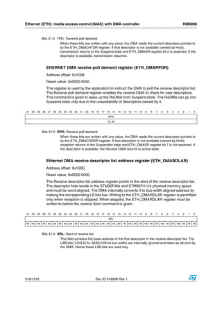


Manual completo ARM
- 1. RM0090 Reference manual STM32F405xx, STM32F407xx, STM32F415xx and STM32F417xx advanced ARM-based 32-bit MCUs Introduction This reference manual targets application developers. It provides complete information on how to use the STM32F405xx, STM32F407xx, STM32F415xx and STM32F417xx microcontroller memory and peripherals. The STM32F405xx, STM32F407xx, STM32F415xx and STM32F417xx will be referred to as STM32F40x and STM32F41x throughout the document, unless otherwise specified. The STM32F40x and STM32F41x constitute a family of microcontrollers with different memory sizes, packages and peripherals. For ordering information, mechanical and electrical device characteristics please refer to the STM32F40x and STM32F41x datasheets. For information on programming, erasing and protection of the internal Flash memory please refer to the STM32F40x and STM32F41x Flash programming manual. For information on the ARM Cortex™-M4F core, please refer to the Cortex™-M4F Technical Reference Manual. Related documents Available from www.arm.com: ■ Cortex™-M4F Technical Reference Manual, available from: http://infocenter.arm.com/help/topic/com.arm.doc.ddi0439c/DDI0439C_cortex_m4_r0p1_trm.pdf Available from STMicroelectronics web site (http://www/st.com): ■ STM32F40x and STM32F41x datasheets ■ STM32F40x and STM32F41x Flash programming manual (PM0081) September 2011 Doc ID 018909 Rev 1 1/1316 www.st.com
- 2. Contents RM0090 Contents 1 Documentation conventions . . . . . . . . . . . . . . . . . . . . . . . . . . . . . . . . . 46 1.1 1.2 2 List of abbreviations for registers . . . . . . . . . . . . . . . . . . . . . . . . . . . . . . . 46 Peripheral availability . . . . . . . . . . . . . . . . . . . . . . . . . . . . . . . . . . . . . . . . 46 Memory and bus architecture . . . . . . . . . . . . . . . . . . . . . . . . . . . . . . . . 47 2.1 System architecture . . . . . . . . . . . . . . . . . . . . . . . . . . . . . . . . . . . . . . . . . 47 2.1.1 S0: I-bus . . . . . . . . . . . . . . . . . . . . . . . . . . . . . . . . . . . . . . . . . . . . . . . . 48 2.1.2 S1: D-bus . . . . . . . . . . . . . . . . . . . . . . . . . . . . . . . . . . . . . . . . . . . . . . . . 48 2.1.3 S2: S-bus . . . . . . . . . . . . . . . . . . . . . . . . . . . . . . . . . . . . . . . . . . . . . . . . 48 2.1.4 S3, S4: DMA memory bus . . . . . . . . . . . . . . . . . . . . . . . . . . . . . . . . . . . 48 2.1.5 S5: DMA peripheral bus . . . . . . . . . . . . . . . . . . . . . . . . . . . . . . . . . . . . . 49 2.1.6 S6: Ethernet DMA bus . . . . . . . . . . . . . . . . . . . . . . . . . . . . . . . . . . . . . . 49 2.1.7 S7: USB OTG HS DMA bus . . . . . . . . . . . . . . . . . . . . . . . . . . . . . . . . . . 49 2.1.8 BusMatrix . . . . . . . . . . . . . . . . . . . . . . . . . . . . . . . . . . . . . . . . . . . . . . . . 49 2.1.9 AHB/APB bridges (APB) . . . . . . . . . . . . . . . . . . . . . . . . . . . . . . . . . . . . 49 2.2 Memory organization . . . . . . . . . . . . . . . . . . . . . . . . . . . . . . . . . . . . . . . . 49 2.3 Memory map . . . . . . . . . . . . . . . . . . . . . . . . . . . . . . . . . . . . . . . . . . . . . . 50 2.3.1 2.3.2 Embedded Flash memory . . . . . . . . . . . . . . . . . . . . . . . . . . . . . . . . . . . 54 2.3.4 Flash memory read interface . . . . . . . . . . . . . . . . . . . . . . . . . . . . . . . . . 54 2.3.5 3 Bit banding . . . . . . . . . . . . . . . . . . . . . . . . . . . . . . . . . . . . . . . . . . . . . . . 53 2.3.3 2.4 Embedded SRAM . . . . . . . . . . . . . . . . . . . . . . . . . . . . . . . . . . . . . . . . . 52 Adaptive real-time memory accelerator (ART Accelerator™) . . . . . . . . 57 Boot configuration . . . . . . . . . . . . . . . . . . . . . . . . . . . . . . . . . . . . . . . . . . 57 CRC calculation unit . . . . . . . . . . . . . . . . . . . . . . . . . . . . . . . . . . . . . . . . 60 3.1 CRC introduction . . . . . . . . . . . . . . . . . . . . . . . . . . . . . . . . . . . . . . . . . . . 60 3.2 CRC main features . . . . . . . . . . . . . . . . . . . . . . . . . . . . . . . . . . . . . . . . . . 60 3.3 CRC functional description . . . . . . . . . . . . . . . . . . . . . . . . . . . . . . . . . . . . 60 3.4 CRC registers . . . . . . . . . . . . . . . . . . . . . . . . . . . . . . . . . . . . . . . . . . . . . . 61 3.4.1 3.4.2 Independent data register (CRC_IDR) . . . . . . . . . . . . . . . . . . . . . . . . . 61 3.4.3 Control register (CRC_CR) . . . . . . . . . . . . . . . . . . . . . . . . . . . . . . . . . . 62 3.4.4 2/1316 Data register (CRC_DR) . . . . . . . . . . . . . . . . . . . . . . . . . . . . . . . . . . . . 61 CRC register map . . . . . . . . . . . . . . . . . . . . . . . . . . . . . . . . . . . . . . . . . 62 Doc ID 018909 Rev 1
- 3. RM0090 4 Contents Power control (PWR) . . . . . . . . . . . . . . . . . . . . . . . . . . . . . . . . . . . . . . . . 63 4.1 Power supplies . . . . . . . . . . . . . . . . . . . . . . . . . . . . . . . . . . . . . . . . . . . . . 63 4.1.1 4.1.2 Battery backup domain . . . . . . . . . . . . . . . . . . . . . . . . . . . . . . . . . . . . . 65 4.1.3 4.2 Independent A/D converter supply and reference voltage . . . . . . . . . . . 64 Voltage regulator . . . . . . . . . . . . . . . . . . . . . . . . . . . . . . . . . . . . . . . . . . 67 Power supply supervisor . . . . . . . . . . . . . . . . . . . . . . . . . . . . . . . . . . . . . 68 4.2.1 4.2.2 Brownout reset (BOR) . . . . . . . . . . . . . . . . . . . . . . . . . . . . . . . . . . . . . . 68 4.2.3 4.3 Power-on reset (POR)/power-down reset (PDR) . . . . . . . . . . . . . . . . . . 68 Programmable voltage detector (PVD) . . . . . . . . . . . . . . . . . . . . . . . . . 69 Low-power modes . . . . . . . . . . . . . . . . . . . . . . . . . . . . . . . . . . . . . . . . . . 70 4.3.1 4.3.2 Peripheral clock gating . . . . . . . . . . . . . . . . . . . . . . . . . . . . . . . . . . . . . . 71 4.3.3 Sleep mode . . . . . . . . . . . . . . . . . . . . . . . . . . . . . . . . . . . . . . . . . . . . . . 71 4.3.4 Stop mode . . . . . . . . . . . . . . . . . . . . . . . . . . . . . . . . . . . . . . . . . . . . . . . 72 4.3.5 Standby mode . . . . . . . . . . . . . . . . . . . . . . . . . . . . . . . . . . . . . . . . . . . . 73 4.3.6 4.4 Slowing down system clocks . . . . . . . . . . . . . . . . . . . . . . . . . . . . . . . . . 70 Programming the RTC alternate functions to wake up the device from the Stop and Standby modes . . . . . . . . . . . . . . . . . . . . . . . . . . . . . . . . 75 Power control registers . . . . . . . . . . . . . . . . . . . . . . . . . . . . . . . . . . . . . . . 78 4.4.1 4.4.2 PWR power control/status register (PWR_CSR) . . . . . . . . . . . . . . . . . . 79 4.4.3 5 PWR power control register (PWR_CR) . . . . . . . . . . . . . . . . . . . . . . . . 78 PWR register map . . . . . . . . . . . . . . . . . . . . . . . . . . . . . . . . . . . . . . . . . 81 Reset and clock control (RCC) . . . . . . . . . . . . . . . . . . . . . . . . . . . . . . . . 82 5.1 Reset . . . . . . . . . . . . . . . . . . . . . . . . . . . . . . . . . . . . . . . . . . . . . . . . . . . . 82 5.1.1 5.1.2 Power reset . . . . . . . . . . . . . . . . . . . . . . . . . . . . . . . . . . . . . . . . . . . . . . 83 5.1.3 5.2 System reset . . . . . . . . . . . . . . . . . . . . . . . . . . . . . . . . . . . . . . . . . . . . . 82 Backup domain reset . . . . . . . . . . . . . . . . . . . . . . . . . . . . . . . . . . . . . . . 84 Clocks . . . . . . . . . . . . . . . . . . . . . . . . . . . . . . . . . . . . . . . . . . . . . . . . . . . . 84 5.2.1 HSE clock . . . . . . . . . . . . . . . . . . . . . . . . . . . . . . . . . . . . . . . . . . . . . . . 86 5.2.2 HSI clock . . . . . . . . . . . . . . . . . . . . . . . . . . . . . . . . . . . . . . . . . . . . . . . . 87 5.2.3 PLL configuration . . . . . . . . . . . . . . . . . . . . . . . . . . . . . . . . . . . . . . . . . . 88 5.2.4 LSE clock . . . . . . . . . . . . . . . . . . . . . . . . . . . . . . . . . . . . . . . . . . . . . . . . 88 5.2.5 LSI clock . . . . . . . . . . . . . . . . . . . . . . . . . . . . . . . . . . . . . . . . . . . . . . . . 89 5.2.6 System clock (SYSCLK) selection . . . . . . . . . . . . . . . . . . . . . . . . . . . . . 89 5.2.7 Clock security system (CSS) . . . . . . . . . . . . . . . . . . . . . . . . . . . . . . . . . 89 5.2.8 RTC/AWU clock . . . . . . . . . . . . . . . . . . . . . . . . . . . . . . . . . . . . . . . . . . . 90 5.2.9 Watchdog clock . . . . . . . . . . . . . . . . . . . . . . . . . . . . . . . . . . . . . . . . . . . 90 Doc ID 018909 Rev 1 3/1316
- 4. Contents RM0090 5.2.10 5.2.11 5.3 Clock-out capability . . . . . . . . . . . . . . . . . . . . . . . . . . . . . . . . . . . . . . . . 91 Internal/external clock measurement using TIM5/TIM11 . . . . . . . . . . . . 91 RCC registers . . . . . . . . . . . . . . . . . . . . . . . . . . . . . . . . . . . . . . . . . . . . . . 93 5.3.1 5.3.2 RCC PLL configuration register (RCC_PLLCFGR) . . . . . . . . . . . . . . . . 95 5.3.3 RCC clock configuration register (RCC_CFGR) . . . . . . . . . . . . . . . . . . 97 5.3.4 RCC clock interrupt register (RCC_CIR) . . . . . . . . . . . . . . . . . . . . . . . . 99 5.3.5 RCC AHB1 peripheral reset register (RCC_AHB1RSTR) . . . . . . . . . . 102 5.3.6 RCC AHB2 peripheral reset register (RCC_AHB2RSTR) . . . . . . . . . . 104 5.3.7 RCC AHB3 peripheral reset register (RCC_AHB3RSTR) . . . . . . . . . . 105 5.3.8 RCC APB1 peripheral reset register (RCC_APB1RSTR) . . . . . . . . . . 105 5.3.9 RCC APB2 peripheral reset register (RCC_APB2RSTR) . . . . . . . . . . 108 5.3.10 RCC AHB1 peripheral clock register (RCC_AHB1ENR) . . . . . . . . . . . 110 5.3.11 RCC AHB2 peripheral clock enable register (RCC_AHB2ENR) . . . . . 112 5.3.12 RCC AHB3 peripheral clock enable register (RCC_AHB3ENR) . . . . . 113 5.3.13 RCC APB1 peripheral clock enable register (RCC_APB1ENR) . . . . . 113 5.3.14 RCC APB2 peripheral clock enable register (RCC_APB2ENR) . . . . . 117 5.3.15 RCC AHB1 peripheral clock enable in low power mode register (RCC_AHB1LPENR) . . . . . . . . . . . . . . . . . . . . . . . . . . . . . . . . . . . . . . 119 5.3.16 RCC AHB2 peripheral clock enable in low power mode register (RCC_AHB2LPENR) . . . . . . . . . . . . . . . . . . . . . . . . . . . . . . . . . . . . . . 121 5.3.17 RCC AHB3 peripheral clock enable in low power mode register (RCC_AHB3LPENR) . . . . . . . . . . . . . . . . . . . . . . . . . . . . . . . . . . . . . . 122 5.3.18 RCC APB1 peripheral clock enable in low power mode register (RCC_APB1LPENR) . . . . . . . . . . . . . . . . . . . . . . . . . . . . . . . . . . . . . . 123 5.3.19 RCC APB2 peripheral clock enabled in low power mode register (RCC_APB2LPENR) . . . . . . . . . . . . . . . . . . . . . . . . . . . . . . . . . . . . . . 126 5.3.20 RCC Backup domain control register (RCC_BDCR) . . . . . . . . . . . . . . 128 5.3.21 RCC clock control & status register (RCC_CSR) . . . . . . . . . . . . . . . . 129 5.3.22 RCC spread spectrum clock generation register (RCC_SSCGR) . . . . 131 5.3.23 RCC PLLI2S configuration register (RCC_PLLI2SCFGR) . . . . . . . . . 132 5.3.24 6 RCC clock control register (RCC_CR) . . . . . . . . . . . . . . . . . . . . . . . . . . 93 RCC register map . . . . . . . . . . . . . . . . . . . . . . . . . . . . . . . . . . . . . . . . 134 General-purpose I/Os (GPIO) . . . . . . . . . . . . . . . . . . . . . . . . . . . . . . . . 136 6.1 GPIO introduction . . . . . . . . . . . . . . . . . . . . . . . . . . . . . . . . . . . . . . . . . . 136 6.2 GPIO main features . . . . . . . . . . . . . . . . . . . . . . . . . . . . . . . . . . . . . . . . 136 6.3 GPIO functional description . . . . . . . . . . . . . . . . . . . . . . . . . . . . . . . . . . 136 6.3.1 4/1316 General-purpose I/O (GPIO) . . . . . . . . . . . . . . . . . . . . . . . . . . . . . . . . 138 Doc ID 018909 Rev 1
- 5. RM0090 Contents 6.3.2 6.3.3 I/O port control registers . . . . . . . . . . . . . . . . . . . . . . . . . . . . . . . . . . . 141 6.3.4 I/O port data registers . . . . . . . . . . . . . . . . . . . . . . . . . . . . . . . . . . . . . 141 6.3.5 I/O data bitwise handling . . . . . . . . . . . . . . . . . . . . . . . . . . . . . . . . . . . 142 6.3.6 GPIO locking mechanism . . . . . . . . . . . . . . . . . . . . . . . . . . . . . . . . . . 142 6.3.7 I/O alternate function input/output . . . . . . . . . . . . . . . . . . . . . . . . . . . . 142 6.3.8 External interrupt/wakeup lines . . . . . . . . . . . . . . . . . . . . . . . . . . . . . . 143 6.3.9 Input configuration . . . . . . . . . . . . . . . . . . . . . . . . . . . . . . . . . . . . . . . . 143 6.3.10 Output configuration . . . . . . . . . . . . . . . . . . . . . . . . . . . . . . . . . . . . . . 144 6.3.11 Alternate function configuration . . . . . . . . . . . . . . . . . . . . . . . . . . . . . . 144 6.3.12 Analog configuration . . . . . . . . . . . . . . . . . . . . . . . . . . . . . . . . . . . . . . 145 6.3.13 Using the OSC32_IN/OSC32_OUT pins as GPIO PC14/PC15 port pins . . . . . . . . . . . . . . . . . . . . . . . . . . . . . . . . . . . . . . . . . . . . . . . . 146 6.3.14 Using the OSC_IN/OSC_OUT pins as GPIO PH0/PH1 port pins . . . . 146 6.3.15 6.4 I/O pin multiplexer and mapping . . . . . . . . . . . . . . . . . . . . . . . . . . . . . 139 Selection of RTC_AF1 and RTC_AF2 alternate functions . . . . . . . . . . 146 GPIO registers . . . . . . . . . . . . . . . . . . . . . . . . . . . . . . . . . . . . . . . . . . . . 148 6.4.1 6.4.2 GPIO port output type register (GPIOx_OTYPER) (x = A..I) . . . . . . . . 148 6.4.3 GPIO port output speed register (GPIOx_OSPEEDR) (x = A..I) . . . . . . . . . . . . . . . . . . . . . . . . . . . . . . . . . . . . . . . . . . . . . . . . 149 6.4.4 GPIO port pull-up/pull-down register (GPIOx_PUPDR) (x = A..I) . . . . . . . . . . . . . . . . . . . . . . . . . . . . . . . . . . . . . . . . . . . . . . . . 149 6.4.5 GPIO port input data register (GPIOx_IDR) (x = A..I) . . . . . . . . . . . . . 150 6.4.6 GPIO port output data register (GPIOx_ODR) (x = A..I) . . . . . . . . . . . 150 6.4.7 GPIO port bit set/reset register (GPIOx_BSRR) (x = A..I) . . . . . . . . . . 150 6.4.8 GPIO port configuration lock register (GPIOx_LCKR) (x = A..I) . . . . . . . . . . . . . . . . . . . . . . . . . . . . . . . . . . . . . . . . . . . . . . . . 151 6.4.9 GPIO alternate function low register (GPIOx_AFRL) (x = A..I) . . . . . . 152 6.4.10 GPIO alternate function high register (GPIOx_AFRH) (x = A..I) . . . . . . . . . . . . . . . . . . . . . . . . . . . . . . . . . . . . . . . . . . . . . . . . 153 6.4.11 7 GPIO port mode register (GPIOx_MODER) (x = A..I) . . . . . . . . . . . . . 148 GPIO register map . . . . . . . . . . . . . . . . . . . . . . . . . . . . . . . . . . . . . . . . 153 System configuration controller (SYSCFG) . . . . . . . . . . . . . . . . . . . . 155 7.1 I/O compensation cell . . . . . . . . . . . . . . . . . . . . . . . . . . . . . . . . . . . . . . . 155 7.2 SYSCFG registers . . . . . . . . . . . . . . . . . . . . . . . . . . . . . . . . . . . . . . . . . 155 7.2.1 SYSCFG memory remap register (SYSCFG_MEMRMP) . . . . . . . . . . 155 7.2.2 SYSCFG peripheral mode configuration register (SYSCFG_PMC) . . 156 7.2.3 SYSCFG external interrupt configuration register 1 (SYSCFG_EXTICR1) . . . . . . . . . . . . . . . . . . . . . . . . . . . . . . . . . . . . . 156 Doc ID 018909 Rev 1 5/1316
- 6. Contents RM0090 7.2.4 7.2.5 SYSCFG external interrupt configuration register 3 (SYSCFG_EXTICR3) . . . . . . . . . . . . . . . . . . . . . . . . . . . . . . . . . . . . . 157 7.2.6 SYSCFG external interrupt configuration register 4 (SYSCFG_EXTICR4) . . . . . . . . . . . . . . . . . . . . . . . . . . . . . . . . . . . . . 158 7.2.7 Compensation cell control register (SYSCFG_CMPCR) . . . . . . . . . . . 158 7.2.8 8 SYSCFG external interrupt configuration register 2 (SYSCFG_EXTICR2) . . . . . . . . . . . . . . . . . . . . . . . . . . . . . . . . . . . . . 157 SYSCFG register maps . . . . . . . . . . . . . . . . . . . . . . . . . . . . . . . . . . . . 159 DMA controller (DMA) . . . . . . . . . . . . . . . . . . . . . . . . . . . . . . . . . . . . . . 160 8.1 DMA introduction . . . . . . . . . . . . . . . . . . . . . . . . . . . . . . . . . . . . . . . . . . 160 8.2 DMA main features . . . . . . . . . . . . . . . . . . . . . . . . . . . . . . . . . . . . . . . . . 161 8.3 DMA functional description . . . . . . . . . . . . . . . . . . . . . . . . . . . . . . . . . . 162 8.3.1 General description . . . . . . . . . . . . . . . . . . . . . . . . . . . . . . . . . . . . . . . 162 8.3.2 DMA transactions . . . . . . . . . . . . . . . . . . . . . . . . . . . . . . . . . . . . . . . . 163 8.3.3 Channel selection . . . . . . . . . . . . . . . . . . . . . . . . . . . . . . . . . . . . . . . . 164 8.3.4 Arbiter . . . . . . . . . . . . . . . . . . . . . . . . . . . . . . . . . . . . . . . . . . . . . . . . . 165 8.3.5 DMA streams . . . . . . . . . . . . . . . . . . . . . . . . . . . . . . . . . . . . . . . . . . . . 165 8.3.6 Source, destination and transfer modes . . . . . . . . . . . . . . . . . . . . . . . 166 8.3.7 Pointer incrementation . . . . . . . . . . . . . . . . . . . . . . . . . . . . . . . . . . . . . 169 8.3.8 Circular mode . . . . . . . . . . . . . . . . . . . . . . . . . . . . . . . . . . . . . . . . . . . 170 8.3.9 Double buffer mode . . . . . . . . . . . . . . . . . . . . . . . . . . . . . . . . . . . . . . . 170 8.3.10 Programmable data width, packing/unpacking, endianess . . . . . . . . . 171 8.3.11 Single and burst transfers . . . . . . . . . . . . . . . . . . . . . . . . . . . . . . . . . . 173 8.3.12 FIFO . . . . . . . . . . . . . . . . . . . . . . . . . . . . . . . . . . . . . . . . . . . . . . . . . . . 173 8.3.13 DMA transfer completion . . . . . . . . . . . . . . . . . . . . . . . . . . . . . . . . . . . 176 8.3.14 DMA transfer suspension . . . . . . . . . . . . . . . . . . . . . . . . . . . . . . . . . . . 177 8.3.15 Flow controller . . . . . . . . . . . . . . . . . . . . . . . . . . . . . . . . . . . . . . . . . . . 177 8.3.16 Summary of the possible DMA configurations . . . . . . . . . . . . . . . . . . . 178 8.3.17 Stream configuration procedure . . . . . . . . . . . . . . . . . . . . . . . . . . . . . 179 8.3.18 Error management . . . . . . . . . . . . . . . . . . . . . . . . . . . . . . . . . . . . . . . . 180 8.4 DMA interrupts . . . . . . . . . . . . . . . . . . . . . . . . . . . . . . . . . . . . . . . . . . . . 181 8.5 DMA registers . . . . . . . . . . . . . . . . . . . . . . . . . . . . . . . . . . . . . . . . . . . . . 181 8.5.1 8.5.2 DMA high interrupt status register (DMA_HISR) . . . . . . . . . . . . . . . . . 182 8.5.3 DMA low interrupt flag clear register (DMA_LIFCR) . . . . . . . . . . . . . . 183 8.5.4 6/1316 DMA low interrupt status register (DMA_LISR) . . . . . . . . . . . . . . . . . . 181 DMA high interrupt flag clear register (DMA_HIFCR) . . . . . . . . . . . . . 184 Doc ID 018909 Rev 1
- 7. RM0090 Contents 8.5.5 8.5.6 DMA stream x number of data register (DMA_SxNDTR) (x = 0..7) . . . 188 8.5.7 DMA stream x peripheral address register (DMA_SxPAR) (x = 0..7) . 188 8.5.8 DMA stream x memory 0 address register (DMA_SxM0AR) (x = 0..7) 188 8.5.9 DMA stream x memory 1 address register (DMA_SxM1AR) (x = 0..7) 189 8.5.10 DMA stream x FIFO control register (DMA_SxFCR) (x = 0..7) . . . . . . 190 8.5.11 9 DMA stream x configuration register (DMA_SxCR) (x = 0..7) . . . . . . . 185 DMA register map . . . . . . . . . . . . . . . . . . . . . . . . . . . . . . . . . . . . . . . . 191 Interrupts and events . . . . . . . . . . . . . . . . . . . . . . . . . . . . . . . . . . . . . . 195 9.1 Nested vectored interrupt controller (NVIC) . . . . . . . . . . . . . . . . . . . . . . 195 9.1.1 9.1.2 SysTick calibration value register . . . . . . . . . . . . . . . . . . . . . . . . . . . . 195 9.1.3 9.2 NVIC features . . . . . . . . . . . . . . . . . . . . . . . . . . . . . . . . . . . . . . . . . . . 195 Interrupt and exception vectors . . . . . . . . . . . . . . . . . . . . . . . . . . . . . . 195 External interrupt/event controller (EXTI) . . . . . . . . . . . . . . . . . . . . . . . . 199 9.2.1 9.2.2 EXTI block diagram . . . . . . . . . . . . . . . . . . . . . . . . . . . . . . . . . . . . . . . 199 9.2.3 Wakeup event management . . . . . . . . . . . . . . . . . . . . . . . . . . . . . . . . 200 9.2.4 Functional description . . . . . . . . . . . . . . . . . . . . . . . . . . . . . . . . . . . . . 200 9.2.5 9.3 EXTI main features . . . . . . . . . . . . . . . . . . . . . . . . . . . . . . . . . . . . . . . 199 External interrupt/event line mapping . . . . . . . . . . . . . . . . . . . . . . . . . 201 EXTI registers . . . . . . . . . . . . . . . . . . . . . . . . . . . . . . . . . . . . . . . . . . . . . 203 9.3.1 9.3.2 Event mask register (EXTI_EMR) . . . . . . . . . . . . . . . . . . . . . . . . . . . . 203 9.3.3 Rising trigger selection register (EXTI_RTSR) . . . . . . . . . . . . . . . . . . 204 9.3.4 Falling trigger selection register (EXTI_FTSR) . . . . . . . . . . . . . . . . . . 204 9.3.5 Software interrupt event register (EXTI_SWIER) . . . . . . . . . . . . . . . . . 205 9.3.6 Pending register (EXTI_PR) . . . . . . . . . . . . . . . . . . . . . . . . . . . . . . . . 205 9.3.7 10 Interrupt mask register (EXTI_IMR) . . . . . . . . . . . . . . . . . . . . . . . . . . . 203 EXTI register map . . . . . . . . . . . . . . . . . . . . . . . . . . . . . . . . . . . . . . . . 206 Analog-to-digital converter (ADC) . . . . . . . . . . . . . . . . . . . . . . . . . . . . 207 10.1 ADC introduction . . . . . . . . . . . . . . . . . . . . . . . . . . . . . . . . . . . . . . . . . . 207 10.2 ADC main features . . . . . . . . . . . . . . . . . . . . . . . . . . . . . . . . . . . . . . . . . 207 10.3 ADC functional description . . . . . . . . . . . . . . . . . . . . . . . . . . . . . . . . . . . 207 10.3.1 ADC on-off control . . . . . . . . . . . . . . . . . . . . . . . . . . . . . . . . . . . . . . . . 209 10.3.2 ADC clock . . . . . . . . . . . . . . . . . . . . . . . . . . . . . . . . . . . . . . . . . . . . . . 209 10.3.3 Channel selection . . . . . . . . . . . . . . . . . . . . . . . . . . . . . . . . . . . . . . . . 209 10.3.4 Single conversion mode . . . . . . . . . . . . . . . . . . . . . . . . . . . . . . . . . . . . 210 10.3.5 Continuous conversion mode . . . . . . . . . . . . . . . . . . . . . . . . . . . . . . . 210 Doc ID 018909 Rev 1 7/1316
- 8. Contents RM0090 10.3.6 Timing diagram . . . . . . . . . . . . . . . . . . . . . . . . . . . . . . . . . . . . . . . . . . 211 10.3.7 Analog watchdog . . . . . . . . . . . . . . . . . . . . . . . . . . . . . . . . . . . . . . . . . 211 10.3.8 Scan mode . . . . . . . . . . . . . . . . . . . . . . . . . . . . . . . . . . . . . . . . . . . . . . 212 10.3.9 Injected channel management . . . . . . . . . . . . . . . . . . . . . . . . . . . . . . . 212 10.3.10 Discontinuous mode . . . . . . . . . . . . . . . . . . . . . . . . . . . . . . . . . . . . . . 213 10.4 Data alignment . . . . . . . . . . . . . . . . . . . . . . . . . . . . . . . . . . . . . . . . . . . . 214 10.5 Channel-wise programmable sampling time . . . . . . . . . . . . . . . . . . . . . 215 10.6 Conversion on external trigger and trigger polarity . . . . . . . . . . . . . . . . 216 10.7 Fast conversion mode . . . . . . . . . . . . . . . . . . . . . . . . . . . . . . . . . . . . . . 217 10.8 Data management . . . . . . . . . . . . . . . . . . . . . . . . . . . . . . . . . . . . . . . . . 218 10.8.1 10.8.2 Managing a sequence of conversions without using the DMA . . . . . . 218 10.8.3 10.9 Using the DMA . . . . . . . . . . . . . . . . . . . . . . . . . . . . . . . . . . . . . . . . . . . 218 Conversions without DMA and without overrun detection . . . . . . . . . . 218 Multi ADC mode . . . . . . . . . . . . . . . . . . . . . . . . . . . . . . . . . . . . . . . . . . . 219 10.9.1 Injected simultaneous mode . . . . . . . . . . . . . . . . . . . . . . . . . . . . . . . . 222 10.9.2 Regular simultaneous mode . . . . . . . . . . . . . . . . . . . . . . . . . . . . . . . . 223 10.9.3 Interleaved mode . . . . . . . . . . . . . . . . . . . . . . . . . . . . . . . . . . . . . . . . . 225 10.9.4 Alternate trigger mode . . . . . . . . . . . . . . . . . . . . . . . . . . . . . . . . . . . . . 226 10.9.5 Combined regular/injected simultaneous mode . . . . . . . . . . . . . . . . . . 228 10.9.6 Combined regular simultaneous + alternate trigger mode . . . . . . . . . . 228 10.10 Temperature sensor . . . . . . . . . . . . . . . . . . . . . . . . . . . . . . . . . . . . . . . . 229 10.11 Battery charge monitoring . . . . . . . . . . . . . . . . . . . . . . . . . . . . . . . . . . . 230 10.12 ADC interrupts . . . . . . . . . . . . . . . . . . . . . . . . . . . . . . . . . . . . . . . . . . . . 231 10.13 ADC registers . . . . . . . . . . . . . . . . . . . . . . . . . . . . . . . . . . . . . . . . . . . . . 232 10.13.1 ADC status register (ADC_SR) . . . . . . . . . . . . . . . . . . . . . . . . . . . . . . 232 10.13.2 ADC control register 1 (ADC_CR1) . . . . . . . . . . . . . . . . . . . . . . . . . . . 233 10.13.3 ADC control register 2 (ADC_CR2) . . . . . . . . . . . . . . . . . . . . . . . . . . . 235 10.13.4 ADC sample time register 1 (ADC_SMPR1) . . . . . . . . . . . . . . . . . . . . 238 10.13.5 ADC sample time register 2 (ADC_SMPR2) . . . . . . . . . . . . . . . . . . . . 238 10.13.6 ADC injected channel data offset register x (ADC_JOFRx)(x=1..4) . . 239 10.13.7 ADC watchdog higher threshold register (ADC_HTR) . . . . . . . . . . . . . 239 10.13.8 ADC watchdog lower threshold register (ADC_LTR) . . . . . . . . . . . . . . 239 10.13.9 ADC regular sequence register 1 (ADC_SQR1) . . . . . . . . . . . . . . . . . 240 10.13.10 ADC regular sequence register 2 (ADC_SQR2) . . . . . . . . . . . . . . . . . 240 10.13.11 ADC regular sequence register 3 (ADC_SQR3) . . . . . . . . . . . . . . . . . 241 10.13.12 ADC injected sequence register (ADC_JSQR) . . . . . . . . . . . . . . . . . . 241 8/1316 Doc ID 018909 Rev 1
- 9. RM0090 Contents 10.13.13 ADC injected data register x (ADC_JDRx) (x= 1..4) . . . . . . . . . . . . . . 242 10.13.14 ADC regular data register (ADC_DR) . . . . . . . . . . . . . . . . . . . . . . . . . 242 10.13.15 ADC Common status register (ADC_CSR) . . . . . . . . . . . . . . . . . . . . . 244 10.13.16 ADC common control register (ADC_CCR) . . . . . . . . . . . . . . . . . . . . . 245 10.13.17 ADC common regular data register for dual and triple modes (ADC_CDR) . . . . . . . . . . . . . . . . . . . . . . . . . . . . . . . . . . . . . . . . . . . . . 247 10.13.18 ADC register map . . . . . . . . . . . . . . . . . . . . . . . . . . . . . . . . . . . . . . . . 247 11 Digital-to-analog converter (DAC) . . . . . . . . . . . . . . . . . . . . . . . . . . . . 250 11.1 DAC introduction . . . . . . . . . . . . . . . . . . . . . . . . . . . . . . . . . . . . . . . . . . 250 11.2 DAC main features . . . . . . . . . . . . . . . . . . . . . . . . . . . . . . . . . . . . . . . . . 250 11.3 DAC functional description . . . . . . . . . . . . . . . . . . . . . . . . . . . . . . . . . . . 252 11.3.1 11.3.2 DAC output buffer enable . . . . . . . . . . . . . . . . . . . . . . . . . . . . . . . . . . . 252 11.3.3 DAC data format . . . . . . . . . . . . . . . . . . . . . . . . . . . . . . . . . . . . . . . . . 252 11.3.4 DAC conversion . . . . . . . . . . . . . . . . . . . . . . . . . . . . . . . . . . . . . . . . . . 253 11.3.5 DAC output voltage . . . . . . . . . . . . . . . . . . . . . . . . . . . . . . . . . . . . . . . 254 11.3.6 DAC trigger selection . . . . . . . . . . . . . . . . . . . . . . . . . . . . . . . . . . . . . . 254 11.3.7 DMA request . . . . . . . . . . . . . . . . . . . . . . . . . . . . . . . . . . . . . . . . . . . . 254 11.3.8 Noise generation . . . . . . . . . . . . . . . . . . . . . . . . . . . . . . . . . . . . . . . . . 255 11.3.9 11.4 DAC channel enable . . . . . . . . . . . . . . . . . . . . . . . . . . . . . . . . . . . . . . 252 Triangle-wave generation . . . . . . . . . . . . . . . . . . . . . . . . . . . . . . . . . . . 256 Dual DAC channel conversion . . . . . . . . . . . . . . . . . . . . . . . . . . . . . . . . 257 11.4.1 Independent trigger without wave generation . . . . . . . . . . . . . . . . . . . 257 11.4.2 Independent trigger with single LFSR generation . . . . . . . . . . . . . . . . 258 11.4.3 Independent trigger with different LFSR generation . . . . . . . . . . . . . . 258 11.4.4 Independent trigger with single triangle generation . . . . . . . . . . . . . . . 258 11.4.5 Independent trigger with different triangle generation . . . . . . . . . . . . . 259 11.4.6 Simultaneous software start . . . . . . . . . . . . . . . . . . . . . . . . . . . . . . . . 259 11.4.7 Simultaneous trigger without wave generation . . . . . . . . . . . . . . . . . . 259 11.4.8 Simultaneous trigger with single LFSR generation . . . . . . . . . . . . . . . 260 11.4.9 Simultaneous trigger with different LFSR generation . . . . . . . . . . . . . 260 11.4.10 Simultaneous trigger with single triangle generation . . . . . . . . . . . . . . 260 11.4.11 Simultaneous trigger with different triangle generation . . . . . . . . . . . . 261 11.5 DAC registers . . . . . . . . . . . . . . . . . . . . . . . . . . . . . . . . . . . . . . . . . . . . . 261 11.5.1 DAC control register (DAC_CR) . . . . . . . . . . . . . . . . . . . . . . . . . . . . . . 261 11.5.2 DAC software trigger register (DAC_SWTRIGR) . . . . . . . . . . . . . . . . . 264 Doc ID 018909 Rev 1 9/1316
- 10. Contents RM0090 11.5.3 DAC channel1 12-bit right-aligned data holding register (DAC_DHR12R1) . . . . . . . . . . . . . . . . . . . . . . . . . . . . . . . . . . . . . . . . . 264 11.5.4 DAC channel1 12-bit left aligned data holding register (DAC_DHR12L1) . . . . . . . . . . . . . . . . . . . . . . . . . . . . . . . . . . . . . . . . . 265 11.5.5 DAC channel1 8-bit right aligned data holding register (DAC_DHR8R1) . . . . . . . . . . . . . . . . . . . . . . . . . . . . . . . . . . . . . . . . . . 265 11.5.6 DAC channel2 12-bit right aligned data holding register (DAC_DHR12R2) . . . . . . . . . . . . . . . . . . . . . . . . . . . . . . . . . . . . . . . . . 265 11.5.7 DAC channel2 12-bit left aligned data holding register (DAC_DHR12L2) . . . . . . . . . . . . . . . . . . . . . . . . . . . . . . . . . . . . . . . . . 266 11.5.8 DAC channel2 8-bit right-aligned data holding register (DAC_DHR8R2) . . . . . . . . . . . . . . . . . . . . . . . . . . . . . . . . . . . . . . . . . . 266 11.5.9 Dual DAC 12-bit right-aligned data holding register (DAC_DHR12RD) . . . . . . . . . . . . . . . . . . . . . . . . . . . . . . . . . . . . . . . . 266 11.5.10 DUAL DAC 12-bit left aligned data holding register (DAC_DHR12LD) . . . . . . . . . . . . . . . . . . . . . . . . . . . . . . . . . . . . . . . . . 267 11.5.11 DUAL DAC 8-bit right aligned data holding register (DAC_DHR8RD) . . . . . . . . . . . . . . . . . . . . . . . . . . . . . . . . . . . . . . . . . 267 11.5.12 DAC channel1 data output register (DAC_DOR1) . . . . . . . . . . . . . . . . 268 11.5.13 DAC channel2 data output register (DAC_DOR2) . . . . . . . . . . . . . . . . 268 11.5.14 DAC status register (DAC_SR) . . . . . . . . . . . . . . . . . . . . . . . . . . . . . . 268 11.5.15 DAC register map . . . . . . . . . . . . . . . . . . . . . . . . . . . . . . . . . . . . . . . . 269 12 Digital camera interface (DCMI) . . . . . . . . . . . . . . . . . . . . . . . . . . . . . . 270 12.1 DCMI introduction . . . . . . . . . . . . . . . . . . . . . . . . . . . . . . . . . . . . . . . . . . 270 12.2 DCMI main features . . . . . . . . . . . . . . . . . . . . . . . . . . . . . . . . . . . . . . . . 270 12.3 DCMI pins . . . . . . . . . . . . . . . . . . . . . . . . . . . . . . . . . . . . . . . . . . . . . . . . 270 12.4 DCMI clocks . . . . . . . . . . . . . . . . . . . . . . . . . . . . . . . . . . . . . . . . . . . . . . 270 12.5 DCMI functional overview . . . . . . . . . . . . . . . . . . . . . . . . . . . . . . . . . . . . 271 12.5.1 12.5.2 DCMI physical interface . . . . . . . . . . . . . . . . . . . . . . . . . . . . . . . . . . . . 272 12.5.3 Synchronization . . . . . . . . . . . . . . . . . . . . . . . . . . . . . . . . . . . . . . . . . . 274 12.5.4 Capture modes . . . . . . . . . . . . . . . . . . . . . . . . . . . . . . . . . . . . . . . . . . 276 12.5.5 Crop feature . . . . . . . . . . . . . . . . . . . . . . . . . . . . . . . . . . . . . . . . . . . . . 277 12.5.6 JPEG format . . . . . . . . . . . . . . . . . . . . . . . . . . . . . . . . . . . . . . . . . . . . 278 12.5.7 12.6 DMA interface . . . . . . . . . . . . . . . . . . . . . . . . . . . . . . . . . . . . . . . . . . . 272 FIFO . . . . . . . . . . . . . . . . . . . . . . . . . . . . . . . . . . . . . . . . . . . . . . . . . . . 278 Data format description . . . . . . . . . . . . . . . . . . . . . . . . . . . . . . . . . . . . . 279 12.6.1 12.6.2 10/1316 Data formats . . . . . . . . . . . . . . . . . . . . . . . . . . . . . . . . . . . . . . . . . . . . 279 Monochrome format . . . . . . . . . . . . . . . . . . . . . . . . . . . . . . . . . . . . . . . 279 Doc ID 018909 Rev 1
- 11. RM0090 Contents 12.6.3 RGB format . . . . . . . . . . . . . . . . . . . . . . . . . . . . . . . . . . . . . . . . . . . . . 279 12.6.4 YCbCr format . . . . . . . . . . . . . . . . . . . . . . . . . . . . . . . . . . . . . . . . . . . . 280 12.7 DCMI interrupts . . . . . . . . . . . . . . . . . . . . . . . . . . . . . . . . . . . . . . . . . . . 280 12.8 DCMI register description . . . . . . . . . . . . . . . . . . . . . . . . . . . . . . . . . . . . 281 12.8.1 DCMI control register 1 (DCMI_CR) . . . . . . . . . . . . . . . . . . . . . . . . . . 281 12.8.2 DCMI status register (DCMI_SR) . . . . . . . . . . . . . . . . . . . . . . . . . . . . 283 12.8.3 DCMI raw interrupt status register (DCMI_RIS) . . . . . . . . . . . . . . . . . . 284 12.8.4 DCMI interrupt enable register (DCMI_IER) . . . . . . . . . . . . . . . . . . . . 285 12.8.5 DCMI masked interrupt status register (DCMI_MIS) . . . . . . . . . . . . . . 286 12.8.6 DCMI interrupt clear register (DCMI_ICR) . . . . . . . . . . . . . . . . . . . . . . 287 12.8.7 DCMI embedded synchronization code register (DCMI_ESCR) . . . . . 287 12.8.8 DCMI embedded synchronization unmask register (DCMI_ESUR) . . 288 12.8.9 DCMI crop window start (DCMI_CWSTRT) . . . . . . . . . . . . . . . . . . . . . 290 12.8.10 DCMI crop window size (DCMI_CWSIZE) . . . . . . . . . . . . . . . . . . . . . . 290 12.8.11 DCMI data register (DCMI_DR) . . . . . . . . . . . . . . . . . . . . . . . . . . . . . . 291 12.8.12 DCMI register map . . . . . . . . . . . . . . . . . . . . . . . . . . . . . . . . . . . . . . . . 291 13 Advanced-control timers (TIM1&TIM8) . . . . . . . . . . . . . . . . . . . . . . . . 293 13.1 TIM1&TIM8 introduction . . . . . . . . . . . . . . . . . . . . . . . . . . . . . . . . . . . . . 293 13.2 TIM1&TIM8 main features . . . . . . . . . . . . . . . . . . . . . . . . . . . . . . . . . . . 293 13.3 TIM1&TIM8 functional description . . . . . . . . . . . . . . . . . . . . . . . . . . . . . 295 13.3.1 Time-base unit . . . . . . . . . . . . . . . . . . . . . . . . . . . . . . . . . . . . . . . . . . . 295 13.3.2 Counter modes . . . . . . . . . . . . . . . . . . . . . . . . . . . . . . . . . . . . . . . . . . 296 13.3.3 Repetition counter . . . . . . . . . . . . . . . . . . . . . . . . . . . . . . . . . . . . . . . . 304 13.3.4 Clock selection . . . . . . . . . . . . . . . . . . . . . . . . . . . . . . . . . . . . . . . . . . . 306 13.3.5 Capture/compare channels . . . . . . . . . . . . . . . . . . . . . . . . . . . . . . . . . 309 13.3.6 Input capture mode . . . . . . . . . . . . . . . . . . . . . . . . . . . . . . . . . . . . . . . 310 13.3.7 PWM input mode . . . . . . . . . . . . . . . . . . . . . . . . . . . . . . . . . . . . . . . . . 311 13.3.8 Forced output mode . . . . . . . . . . . . . . . . . . . . . . . . . . . . . . . . . . . . . . . 312 13.3.9 Output compare mode . . . . . . . . . . . . . . . . . . . . . . . . . . . . . . . . . . . . . 313 13.3.10 PWM mode . . . . . . . . . . . . . . . . . . . . . . . . . . . . . . . . . . . . . . . . . . . . . 314 13.3.11 Complementary outputs and dead-time insertion . . . . . . . . . . . . . . . . 317 13.3.12 Using the break function . . . . . . . . . . . . . . . . . . . . . . . . . . . . . . . . . . . 318 13.3.13 Clearing the OCxREF signal on an external event . . . . . . . . . . . . . . . 321 13.3.14 6-step PWM generation . . . . . . . . . . . . . . . . . . . . . . . . . . . . . . . . . . . . 322 13.3.15 One-pulse mode . . . . . . . . . . . . . . . . . . . . . . . . . . . . . . . . . . . . . . . . . 323 13.3.16 Encoder interface mode . . . . . . . . . . . . . . . . . . . . . . . . . . . . . . . . . . . . 324 Doc ID 018909 Rev 1 11/1316
- 12. Contents RM0090 13.3.17 Timer input XOR function . . . . . . . . . . . . . . . . . . . . . . . . . . . . . . . . . . 327 13.3.18 Interfacing with Hall sensors . . . . . . . . . . . . . . . . . . . . . . . . . . . . . . . . 327 13.3.19 TIMx and external trigger synchronization . . . . . . . . . . . . . . . . . . . . . . 329 13.3.20 Timer synchronization . . . . . . . . . . . . . . . . . . . . . . . . . . . . . . . . . . . . . 332 13.3.21 Debug mode . . . . . . . . . . . . . . . . . . . . . . . . . . . . . . . . . . . . . . . . . . . . 332 13.4 TIM1&TIM8 registers . . . . . . . . . . . . . . . . . . . . . . . . . . . . . . . . . . . . . . . 333 13.4.1 TIM1&TIM8 control register 1 (TIMx_CR1) . . . . . . . . . . . . . . . . . . . . . 333 13.4.2 TIM1&TIM8 control register 2 (TIMx_CR2) . . . . . . . . . . . . . . . . . . . . . 334 13.4.3 TIM1&TIM8 slave mode control register (TIMx_SMCR) . . . . . . . . . . . 337 13.4.4 TIM1&TIM8 DMA/interrupt enable register (TIMx_DIER) . . . . . . . . . . 339 13.4.5 TIM1&TIM8 status register (TIMx_SR) . . . . . . . . . . . . . . . . . . . . . . . . 341 13.4.6 TIM1&TIM8 event generation register (TIMx_EGR) . . . . . . . . . . . . . . 342 13.4.7 TIM1&TIM8 capture/compare mode register 1 (TIMx_CCMR1) . . . . . 344 13.4.8 TIM1&TIM8 capture/compare mode register 2 (TIMx_CCMR2) . . . . . 347 13.4.9 TIM1&TIM8 capture/compare enable register (TIMx_CCER) . . . . . . . 348 13.4.10 TIM1&TIM8 counter (TIMx_CNT) . . . . . . . . . . . . . . . . . . . . . . . . . . . . 352 13.4.11 TIM1&TIM8 prescaler (TIMx_PSC) . . . . . . . . . . . . . . . . . . . . . . . . . . . 352 13.4.12 TIM1&TIM8 auto-reload register (TIMx_ARR) . . . . . . . . . . . . . . . . . . . 352 13.4.13 TIM1&TIM8 repetition counter register (TIMx_RCR) . . . . . . . . . . . . . . 353 13.4.14 TIM1&TIM8 capture/compare register 1 (TIMx_CCR1) . . . . . . . . . . . . 353 13.4.15 TIM1&TIM8 capture/compare register 2 (TIMx_CCR2) . . . . . . . . . . . . 354 13.4.16 TIM1&TIM8 capture/compare register 3 (TIMx_CCR3) . . . . . . . . . . . . 354 13.4.17 TIM1&TIM8 capture/compare register 4 (TIMx_CCR4) . . . . . . . . . . . . 355 13.4.18 TIM1&TIM8 break and dead-time register (TIMx_BDTR) . . . . . . . . . . 355 13.4.19 TIM1&TIM8 DMA control register (TIMx_DCR) . . . . . . . . . . . . . . . . . . 357 13.4.20 TIM1&TIM8 DMA address for full transfer (TIMx_DMAR) . . . . . . . . . . 358 13.4.21 TIM1&TIM8 register map . . . . . . . . . . . . . . . . . . . . . . . . . . . . . . . . . . . 359 14 General-purpose timers (TIM2 to TIM5) . . . . . . . . . . . . . . . . . . . . . . . . 361 14.1 TIM2 to TIM5 introduction . . . . . . . . . . . . . . . . . . . . . . . . . . . . . . . . . . . 361 14.2 TIM2 to TIM5 main features . . . . . . . . . . . . . . . . . . . . . . . . . . . . . . . . . . 361 14.3 TIM2 to TIM5 functional description . . . . . . . . . . . . . . . . . . . . . . . . . . . . 362 14.3.1 14.3.2 Counter modes . . . . . . . . . . . . . . . . . . . . . . . . . . . . . . . . . . . . . . . . . . 363 14.3.3 Clock selection . . . . . . . . . . . . . . . . . . . . . . . . . . . . . . . . . . . . . . . . . . . 372 14.3.4 Capture/compare channels . . . . . . . . . . . . . . . . . . . . . . . . . . . . . . . . . 375 14.3.5 12/1316 Time-base unit . . . . . . . . . . . . . . . . . . . . . . . . . . . . . . . . . . . . . . . . . . . 362 Input capture mode . . . . . . . . . . . . . . . . . . . . . . . . . . . . . . . . . . . . . . . 376 Doc ID 018909 Rev 1
- 13. RM0090 Contents 14.3.6 PWM input mode . . . . . . . . . . . . . . . . . . . . . . . . . . . . . . . . . . . . . . . . . 377 14.3.7 Forced output mode . . . . . . . . . . . . . . . . . . . . . . . . . . . . . . . . . . . . . . . 378 14.3.8 Output compare mode . . . . . . . . . . . . . . . . . . . . . . . . . . . . . . . . . . . . . 379 14.3.9 PWM mode . . . . . . . . . . . . . . . . . . . . . . . . . . . . . . . . . . . . . . . . . . . . . 380 14.3.10 One-pulse mode . . . . . . . . . . . . . . . . . . . . . . . . . . . . . . . . . . . . . . . . . 383 14.3.11 Clearing the OCxREF signal on an external event . . . . . . . . . . . . . . . 384 14.3.12 Encoder interface mode . . . . . . . . . . . . . . . . . . . . . . . . . . . . . . . . . . . . 384 14.3.13 Timer input XOR function . . . . . . . . . . . . . . . . . . . . . . . . . . . . . . . . . . 387 14.3.14 Timers and external trigger synchronization . . . . . . . . . . . . . . . . . . . . 387 14.3.15 Timer synchronization . . . . . . . . . . . . . . . . . . . . . . . . . . . . . . . . . . . . . 391 14.3.16 Debug mode . . . . . . . . . . . . . . . . . . . . . . . . . . . . . . . . . . . . . . . . . . . . 391 14.4 TIM2 to TIM5 registers . . . . . . . . . . . . . . . . . . . . . . . . . . . . . . . . . . . . . . 392 14.4.1 TIMx control register 1 (TIMx_CR1) . . . . . . . . . . . . . . . . . . . . . . . . . . 392 14.4.2 TIMx control register 2 (TIMx_CR2) . . . . . . . . . . . . . . . . . . . . . . . . . . 394 14.4.3 TIMx slave mode control register (TIMx_SMCR) . . . . . . . . . . . . . . . . . 395 14.4.4 TIMx DMA/Interrupt enable register (TIMx_DIER) . . . . . . . . . . . . . . . . 396 14.4.5 TIMx status register (TIMx_SR) . . . . . . . . . . . . . . . . . . . . . . . . . . . . . . 397 14.4.6 TIMx event generation register (TIMx_EGR) . . . . . . . . . . . . . . . . . . . . 399 14.4.7 TIMx capture/compare mode register 1 (TIMx_CCMR1) . . . . . . . . . . . 400 14.4.8 TIMx capture/compare mode register 2 (TIMx_CCMR2) . . . . . . . . . . . 403 14.4.9 TIMx capture/compare enable register (TIMx_CCER) . . . . . . . . . . . . . 404 14.4.10 TIMx counter (TIMx_CNT) . . . . . . . . . . . . . . . . . . . . . . . . . . . . . . . . . . 406 14.4.11 TIMx prescaler (TIMx_PSC) . . . . . . . . . . . . . . . . . . . . . . . . . . . . . . . . 406 14.4.12 TIMx auto-reload register (TIMx_ARR) . . . . . . . . . . . . . . . . . . . . . . . . 406 14.4.13 TIMx capture/compare register 1 (TIMx_CCR1) . . . . . . . . . . . . . . . . . 407 14.4.14 TIMx capture/compare register 2 (TIMx_CCR2) . . . . . . . . . . . . . . . . . 407 14.4.15 TIMx capture/compare register 3 (TIMx_CCR3) . . . . . . . . . . . . . . . . . 408 14.4.16 TIMx capture/compare register 4 (TIMx_CCR4) . . . . . . . . . . . . . . . . . 408 14.4.17 TIMx DMA control register (TIMx_DCR) . . . . . . . . . . . . . . . . . . . . . . . 409 14.4.18 TIMx DMA address for full transfer (TIMx_DMAR) . . . . . . . . . . . . . . . 409 14.4.19 TIM2 option register (TIM2_OR) . . . . . . . . . . . . . . . . . . . . . . . . . . . . . 411 14.4.20 TIM5 option register (TIM5_OR) . . . . . . . . . . . . . . . . . . . . . . . . . . . . . 412 14.4.21 TIMx register map . . . . . . . . . . . . . . . . . . . . . . . . . . . . . . . . . . . . . . . . 412 15 General-purpose timers (TIM9 to TIM14) . . . . . . . . . . . . . . . . . . . . . . . 414 15.1 TIM9 to TIM14 introduction . . . . . . . . . . . . . . . . . . . . . . . . . . . . . . . . . . 414 15.2 TIM9 to TIM14 main features . . . . . . . . . . . . . . . . . . . . . . . . . . . . . . . . . 414 Doc ID 018909 Rev 1 13/1316
- 14. Contents RM0090 15.2.1 TIM9/TIM12 main features . . . . . . . . . . . . . . . . . . . . . . . . . . . . . . . . . . 414 15.3 TIM10/TIM11 and TIM13/TIM14 main features . . . . . . . . . . . . . . . . . . . 415 15.4 TIM9 to TIM14 functional description . . . . . . . . . . . . . . . . . . . . . . . . . . . 417 15.4.1 Time-base unit . . . . . . . . . . . . . . . . . . . . . . . . . . . . . . . . . . . . . . . . . . . 417 15.4.2 Counter modes . . . . . . . . . . . . . . . . . . . . . . . . . . . . . . . . . . . . . . . . . . 418 15.4.3 Clock selection . . . . . . . . . . . . . . . . . . . . . . . . . . . . . . . . . . . . . . . . . . . 421 15.4.4 Capture/compare channels . . . . . . . . . . . . . . . . . . . . . . . . . . . . . . . . . 423 15.4.5 Input capture mode . . . . . . . . . . . . . . . . . . . . . . . . . . . . . . . . . . . . . . . 424 15.4.6 PWM input mode (only for TIM9/12) . . . . . . . . . . . . . . . . . . . . . . . . . . 425 15.4.7 Forced output mode . . . . . . . . . . . . . . . . . . . . . . . . . . . . . . . . . . . . . . . 426 15.4.8 Output compare mode . . . . . . . . . . . . . . . . . . . . . . . . . . . . . . . . . . . . . 427 15.4.9 PWM mode . . . . . . . . . . . . . . . . . . . . . . . . . . . . . . . . . . . . . . . . . . . . . 428 15.4.10 One-pulse mode (only for TIM9/12) . . . . . . . . . . . . . . . . . . . . . . . . . . . 429 15.4.11 TIM9/12 external trigger synchronization . . . . . . . . . . . . . . . . . . . . . . . 430 15.4.12 Timer synchronization (TIM9/12) . . . . . . . . . . . . . . . . . . . . . . . . . . . . . 433 15.4.13 Debug mode . . . . . . . . . . . . . . . . . . . . . . . . . . . . . . . . . . . . . . . . . . . . 433 15.5 TIM9 and TIM12 registers . . . . . . . . . . . . . . . . . . . . . . . . . . . . . . . . . . . 434 15.5.1 TIM9/12 control register 1 (TIMx_CR1) . . . . . . . . . . . . . . . . . . . . . . . . 434 15.5.2 TIM9/12 control register 2 (TIMx_CR2) . . . . . . . . . . . . . . . . . . . . . . . . 435 15.5.3 TIM9/12 slave mode control register (TIMx_SMCR) . . . . . . . . . . . . . . 436 15.5.4 TIM9/12 Interrupt enable register (TIMx_DIER) . . . . . . . . . . . . . . . . . 437 15.5.5 TIM9/12 status register (TIMx_SR) . . . . . . . . . . . . . . . . . . . . . . . . . . . 438 15.5.6 TIM9/12 event generation register (TIMx_EGR) . . . . . . . . . . . . . . . . . 439 15.5.7 TIM9/12 capture/compare mode register 1 (TIMx_CCMR1) . . . . . . . . 440 15.5.8 TIM9/12 capture/compare enable register (TIMx_CCER) . . . . . . . . . . 443 15.5.9 TIM9/12 counter (TIMx_CNT) . . . . . . . . . . . . . . . . . . . . . . . . . . . . . . . 444 15.5.10 TIM9/12 prescaler (TIMx_PSC) . . . . . . . . . . . . . . . . . . . . . . . . . . . . . . 444 15.5.11 TIM9/12 auto-reload register (TIMx_ARR) . . . . . . . . . . . . . . . . . . . . . 444 15.5.12 TIM9/12 capture/compare register 1 (TIMx_CCR1) . . . . . . . . . . . . . . 445 15.5.13 TIM9/12 capture/compare register 2 (TIMx_CCR2) . . . . . . . . . . . . . . 445 15.5.14 TIM9/12 register map . . . . . . . . . . . . . . . . . . . . . . . . . . . . . . . . . . . . . . 445 15.6 TIM10/11/13/14 registers . . . . . . . . . . . . . . . . . . . . . . . . . . . . . . . . . . . . 447 15.6.1 15.6.2 TIM10/11/13/14 Interrupt enable register (TIMx_DIER) . . . . . . . . . . . 448 15.6.3 TIM10/11/13/14 status register (TIMx_SR) . . . . . . . . . . . . . . . . . . . . . 448 15.6.4 14/1316 TIM10/11/13/14 control register 1 (TIMx_CR1) . . . . . . . . . . . . . . . . . . 447 TIM10/11/13/14 event generation register (TIMx_EGR) . . . . . . . . . . . 449 Doc ID 018909 Rev 1
- 15. RM0090 Contents 15.6.5 TIM10/11/13/14 capture/compare mode register 1 (TIMx_CCMR1) . . . . . . . . . . . . . . . . . . . . . . . . . . . . . . . . . . . . . . . . . . 450 15.6.6 TIM10/11/13/14 capture/compare enable register (TIMx_CCER) . . . . . . . . . . . . . . . . . . . . . . . . . . . . . . . . . . . . . . . . . . . 452 15.6.7 TIM10/11/13/14 counter (TIMx_CNT) . . . . . . . . . . . . . . . . . . . . . . . . . 453 15.6.8 TIM10/11/13/14 prescaler (TIMx_PSC) . . . . . . . . . . . . . . . . . . . . . . . . 453 15.6.9 TIM10/11/13/14 auto-reload register (TIMx_ARR) . . . . . . . . . . . . . . . 453 15.6.10 TIM10/11/13/14 capture/compare register 1 (TIMx_CCR1) . . . . . . . . 454 15.6.11 TIM11 option register 1 (TIM11_OR) . . . . . . . . . . . . . . . . . . . . . . . . . . 454 15.6.12 TIM10/11/13/14 register map . . . . . . . . . . . . . . . . . . . . . . . . . . . . . . . . 455 16 Basic timers (TIM6&TIM7) . . . . . . . . . . . . . . . . . . . . . . . . . . . . . . . . . . . 456 16.1 TIM6&TIM7 introduction . . . . . . . . . . . . . . . . . . . . . . . . . . . . . . . . . . . . . 456 16.2 TIM6&TIM7 main features . . . . . . . . . . . . . . . . . . . . . . . . . . . . . . . . . . . 456 16.3 TIM6&TIM7 functional description . . . . . . . . . . . . . . . . . . . . . . . . . . . . . 457 16.3.1 16.3.2 Counting mode . . . . . . . . . . . . . . . . . . . . . . . . . . . . . . . . . . . . . . . . . . 458 16.3.3 Clock source . . . . . . . . . . . . . . . . . . . . . . . . . . . . . . . . . . . . . . . . . . . . 461 16.3.4 16.4 Time-base unit . . . . . . . . . . . . . . . . . . . . . . . . . . . . . . . . . . . . . . . . . . . 457 Debug mode . . . . . . . . . . . . . . . . . . . . . . . . . . . . . . . . . . . . . . . . . . . . 461 TIM6&TIM7 registers . . . . . . . . . . . . . . . . . . . . . . . . . . . . . . . . . . . . . . . 462 16.4.1 16.4.2 TIM6&TIM7 control register 2 (TIMx_CR2) . . . . . . . . . . . . . . . . . . . . . 463 16.4.3 TIM6&TIM7 DMA/Interrupt enable register (TIMx_DIER) . . . . . . . . . . 463 16.4.4 TIM6&TIM7 status register (TIMx_SR) . . . . . . . . . . . . . . . . . . . . . . . . 464 16.4.5 TIM6&TIM7 event generation register (TIMx_EGR) . . . . . . . . . . . . . . 464 16.4.6 TIM6&TIM7 counter (TIMx_CNT) . . . . . . . . . . . . . . . . . . . . . . . . . . . . 464 16.4.7 TIM6&TIM7 prescaler (TIMx_PSC) . . . . . . . . . . . . . . . . . . . . . . . . . . . 465 16.4.8 TIM6&TIM7 auto-reload register (TIMx_ARR) . . . . . . . . . . . . . . . . . . . 465 16.4.9 17 TIM6&TIM7 control register 1 (TIMx_CR1) . . . . . . . . . . . . . . . . . . . . . 462 TIM6&TIM7 register map . . . . . . . . . . . . . . . . . . . . . . . . . . . . . . . . . . . 466 Independent watchdog (IWDG) . . . . . . . . . . . . . . . . . . . . . . . . . . . . . . 467 17.1 IWDG introduction . . . . . . . . . . . . . . . . . . . . . . . . . . . . . . . . . . . . . . . . . 467 17.2 IWDG main features . . . . . . . . . . . . . . . . . . . . . . . . . . . . . . . . . . . . . . . . 467 17.3 IWDG functional description . . . . . . . . . . . . . . . . . . . . . . . . . . . . . . . . . . 467 17.3.1 Hardware watchdog . . . . . . . . . . . . . . . . . . . . . . . . . . . . . . . . . . . . . . . 467 17.3.2 Register access protection . . . . . . . . . . . . . . . . . . . . . . . . . . . . . . . . . 467 17.3.3 Debug mode . . . . . . . . . . . . . . . . . . . . . . . . . . . . . . . . . . . . . . . . . . . . 468 Doc ID 018909 Rev 1 15/1316
- 16. Contents RM0090 17.4 IWDG registers . . . . . . . . . . . . . . . . . . . . . . . . . . . . . . . . . . . . . . . . . . . . 468 17.4.1 17.4.2 Prescaler register (IWDG_PR) . . . . . . . . . . . . . . . . . . . . . . . . . . . . . . 470 17.4.3 Reload register (IWDG_RLR) . . . . . . . . . . . . . . . . . . . . . . . . . . . . . . . 470 17.4.4 Status register (IWDG_SR) . . . . . . . . . . . . . . . . . . . . . . . . . . . . . . . . . 471 17.4.5 18 Key register (IWDG_KR) . . . . . . . . . . . . . . . . . . . . . . . . . . . . . . . . . . . 469 IWDG register map . . . . . . . . . . . . . . . . . . . . . . . . . . . . . . . . . . . . . . . 471 Window watchdog (WWDG) . . . . . . . . . . . . . . . . . . . . . . . . . . . . . . . . . 472 18.1 WWDG introduction . . . . . . . . . . . . . . . . . . . . . . . . . . . . . . . . . . . . . . . . 472 18.2 WWDG main features . . . . . . . . . . . . . . . . . . . . . . . . . . . . . . . . . . . . . . 472 18.3 WWDG functional description . . . . . . . . . . . . . . . . . . . . . . . . . . . . . . . . 472 18.4 How to program the watchdog timeout . . . . . . . . . . . . . . . . . . . . . . . . . . 474 18.5 Debug mode . . . . . . . . . . . . . . . . . . . . . . . . . . . . . . . . . . . . . . . . . . . . . . 475 18.6 WWDG registers . . . . . . . . . . . . . . . . . . . . . . . . . . . . . . . . . . . . . . . . . . 476 18.6.1 18.6.2 Configuration register (WWDG_CFR) . . . . . . . . . . . . . . . . . . . . . . . . . 477 18.6.3 Status register (WWDG_SR) . . . . . . . . . . . . . . . . . . . . . . . . . . . . . . . . 477 18.6.4 19 Control register (WWDG_CR) . . . . . . . . . . . . . . . . . . . . . . . . . . . . . . . 476 WWDG register map . . . . . . . . . . . . . . . . . . . . . . . . . . . . . . . . . . . . . . 478 Cryptographic processor (CRYP) . . . . . . . . . . . . . . . . . . . . . . . . . . . . 479 19.1 CRYP introduction . . . . . . . . . . . . . . . . . . . . . . . . . . . . . . . . . . . . . . . . . 479 19.2 CRYP main features . . . . . . . . . . . . . . . . . . . . . . . . . . . . . . . . . . . . . . . . 479 19.3 CRYP functional description . . . . . . . . . . . . . . . . . . . . . . . . . . . . . . . . . . 480 19.3.1 DES/TDES cryptographic core . . . . . . . . . . . . . . . . . . . . . . . . . . . . . . 480 19.3.2 AES cryptographic core . . . . . . . . . . . . . . . . . . . . . . . . . . . . . . . . . . . . 485 19.3.3 Data type . . . . . . . . . . . . . . . . . . . . . . . . . . . . . . . . . . . . . . . . . . . . . . . 492 19.3.4 Initialization vectors - CRYP_IVguatda.com/cmx.p0...1(L/R) . . . . . . . . . . . . . . . . . . . . . . 494 19.3.5 CRYP busy state . . . . . . . . . . . . . . . . . . . . . . . . . . . . . . . . . . . . . . . . . 496 19.3.6 Procedure to perform an encryption or a decryption . . . . . . . . . . . . . . 497 19.3.7 Context swapping . . . . . . . . . . . . . . . . . . . . . . . . . . . . . . . . . . . . . . . . 498 19.4 CRYP interrupts . . . . . . . . . . . . . . . . . . . . . . . . . . . . . . . . . . . . . . . . . . . 499 19.5 CRYP DMA interface . . . . . . . . . . . . . . . . . . . . . . . . . . . . . . . . . . . . . . . 500 19.6 CRYP registers . . . . . . . . . . . . . . . . . . . . . . . . . . . . . . . . . . . . . . . . . . . . 501 19.6.1 19.6.2 CRYP status register (CRYP_SR) . . . . . . . . . . . . . . . . . . . . . . . . . . . . 503 19.6.3 16/1316 CRYP control register (CRYP_CR) . . . . . . . . . . . . . . . . . . . . . . . . . . . 501 CRYP data input register (CRYP_DIN) . . . . . . . . . . . . . . . . . . . . . . . . 504 Doc ID 018909 Rev 1
- 17. RM0090 Contents 19.6.4 CRYP data output register (CRYP_DOUT) . . . . . . . . . . . . . . . . . . . . . 505 19.6.5 CRYP DMA control register (CRYP_DMACR) . . . . . . . . . . . . . . . . . . . 506 19.6.6 CRYP interrupt mask set/clear register (CRYP_IMSCR) . . . . . . . . . . . 506 19.6.7 CRYP raw interrupt status register (CRYP_RISR) . . . . . . . . . . . . . . . . 507 19.6.8 CRYP masked interrupt status register (CRYP_MISR) . . . . . . . . . . . . 507 19.6.9 CRYP key registers (CRYP_Kguatda.com/cmx.p0...3(L/R)R) . . . . . . . . . . . . . . . . . . . . . . 508 19.6.10 CRYP initialization vector registers (CRYP_IVguatda.com/cmx.p0...1(L/R)R) . . . . . . . . . 510 19.6.11 CRYP register map . . . . . . . . . . . . . . . . . . . . . . . . . . . . . . . . . . . . . . . 511 20 Random number generator (RNG) . . . . . . . . . . . . . . . . . . . . . . . . . . . . 513 20.1 RNG introduction . . . . . . . . . . . . . . . . . . . . . . . . . . . . . . . . . . . . . . . . . . 513 20.2 RNG main features . . . . . . . . . . . . . . . . . . . . . . . . . . . . . . . . . . . . . . . . . 513 20.3 RNG functional description . . . . . . . . . . . . . . . . . . . . . . . . . . . . . . . . . . 513 20.3.1 20.3.2 20.4 Operation . . . . . . . . . . . . . . . . . . . . . . . . . . . . . . . . . . . . . . . . . . . . . . . 514 Error management . . . . . . . . . . . . . . . . . . . . . . . . . . . . . . . . . . . . . . . . 514 RNG registers . . . . . . . . . . . . . . . . . . . . . . . . . . . . . . . . . . . . . . . . . . . . . 514 20.4.1 20.4.2 RNG status register (RNG_SR) . . . . . . . . . . . . . . . . . . . . . . . . . . . . . . 515 20.4.3 RNG data register (RNG_DR) . . . . . . . . . . . . . . . . . . . . . . . . . . . . . . . 516 20.4.4 21 RNG control register (RNG_CR) . . . . . . . . . . . . . . . . . . . . . . . . . . . . . 515 RNG register map . . . . . . . . . . . . . . . . . . . . . . . . . . . . . . . . . . . . . . . . 517 Hash processor (HASH) . . . . . . . . . . . . . . . . . . . . . . . . . . . . . . . . . . . . 518 21.1 HASH introduction . . . . . . . . . . . . . . . . . . . . . . . . . . . . . . . . . . . . . . . . . 518 21.2 HASH main features . . . . . . . . . . . . . . . . . . . . . . . . . . . . . . . . . . . . . . . . 518 21.3 HASH functional description . . . . . . . . . . . . . . . . . . . . . . . . . . . . . . . . . 519 21.3.1 21.3.2 Data type . . . . . . . . . . . . . . . . . . . . . . . . . . . . . . . . . . . . . . . . . . . . . . . 520 21.3.3 Message digest computing . . . . . . . . . . . . . . . . . . . . . . . . . . . . . . . . . 521 21.3.4 Message padding . . . . . . . . . . . . . . . . . . . . . . . . . . . . . . . . . . . . . . . . 522 21.3.5 Hash operation . . . . . . . . . . . . . . . . . . . . . . . . . . . . . . . . . . . . . . . . . . 523 21.3.6 HMAC operation . . . . . . . . . . . . . . . . . . . . . . . . . . . . . . . . . . . . . . . . . 524 21.3.7 Context swapping . . . . . . . . . . . . . . . . . . . . . . . . . . . . . . . . . . . . . . . . 524 21.3.8 21.4 Duration of the processing . . . . . . . . . . . . . . . . . . . . . . . . . . . . . . . . . . 520 HASH interrupt . . . . . . . . . . . . . . . . . . . . . . . . . . . . . . . . . . . . . . . . . . . 526 HASH registers . . . . . . . . . . . . . . . . . . . . . . . . . . . . . . . . . . . . . . . . . . . . 526 21.4.1 HASH control register (HASH_CR) . . . . . . . . . . . . . . . . . . . . . . . . . . . 527 21.4.2 HASH data input register (HASH_DIN) . . . . . . . . . . . . . . . . . . . . . . . . 529 Doc ID 018909 Rev 1 17/1316
- 18. Contents RM0090 21.4.3 21.4.4 HASH digest registers (HASH_HRguatda.com/cmx.p0...4) . . . . . . . . . . . . . . . . . . . . . . . 531 21.4.5 HASH interrupt enable register (HASH_IMR) . . . . . . . . . . . . . . . . . . . 532 21.4.6 HASH status register (HASH_SR) . . . . . . . . . . . . . . . . . . . . . . . . . . . . 533 21.4.7 HASH context swap registers (HASH_CSRguatda.com/cmx.p0...50) . . . . . . . . . . . . . . . 534 21.4.8 22 HASH start register (HASH_STR) . . . . . . . . . . . . . . . . . . . . . . . . . . . . 530 HASH register map . . . . . . . . . . . . . . . . . . . . . . . . . . . . . . . . . . . . . . . 535 Real-time clock (RTC) . . . . . . . . . . . . . . . . . . . . . . . . . . . . . . . . . . . . . . 536 22.1 Introduction . . . . . . . . . . . . . . . . . . . . . . . . . . . . . . . . . . . . . . . . . . . . . . 536 22.2 RTC main features . . . . . . . . . . . . . . . . . . . . . . . . . . . . . . . . . . . . . . . . . 537 22.3 RTC functional description . . . . . . . . . . . . . . . . . . . . . . . . . . . . . . . . . . . 538 22.3.1 Clock and prescalers . . . . . . . . . . . . . . . . . . . . . . . . . . . . . . . . . . . . . . 538 22.3.2 Real-time clock and calendar . . . . . . . . . . . . . . . . . . . . . . . . . . . . . . . . 539 22.3.3 Programmable alarms . . . . . . . . . . . . . . . . . . . . . . . . . . . . . . . . . . . . . 539 22.3.4 Periodic auto-wakeup . . . . . . . . . . . . . . . . . . . . . . . . . . . . . . . . . . . . . 540 22.3.5 RTC initialization and configuration . . . . . . . . . . . . . . . . . . . . . . . . . . . 541 22.3.6 Reading the calendar . . . . . . . . . . . . . . . . . . . . . . . . . . . . . . . . . . . . . . 542 22.3.7 Resetting the RTC . . . . . . . . . . . . . . . . . . . . . . . . . . . . . . . . . . . . . . . . 543 22.3.8 RTC synchronization . . . . . . . . . . . . . . . . . . . . . . . . . . . . . . . . . . . . . . 544 22.3.9 RTC reference clock detection . . . . . . . . . . . . . . . . . . . . . . . . . . . . . . . 544 22.3.10 RTC coarse digital calibration . . . . . . . . . . . . . . . . . . . . . . . . . . . . . . . 545 22.3.11 RTC smooth digital calibration . . . . . . . . . . . . . . . . . . . . . . . . . . . . . . 546 22.3.12 Timestamp function . . . . . . . . . . . . . . . . . . . . . . . . . . . . . . . . . . . . . . . 547 22.3.13 Tamper detection . . . . . . . . . . . . . . . . . . . . . . . . . . . . . . . . . . . . . . . . . 548 22.3.14 Calibration clock output . . . . . . . . . . . . . . . . . . . . . . . . . . . . . . . . . . . . 550 22.3.15 Alarm output . . . . . . . . . . . . . . . . . . . . . . . . . . . . . . . . . . . . . . . . . . . . 550 22.4 RTC and low power modes . . . . . . . . . . . . . . . . . . . . . . . . . . . . . . . . . . 551 22.5 RTC interrupts . . . . . . . . . . . . . . . . . . . . . . . . . . . . . . . . . . . . . . . . . . . . 551 22.6 RTC registers . . . . . . . . . . . . . . . . . . . . . . . . . . . . . . . . . . . . . . . . . . . . . 553 22.6.1 22.6.2 RTC date register (RTC_DR) . . . . . . . . . . . . . . . . . . . . . . . . . . . . . . . . 554 22.6.3 RTC control register (RTC_CR) . . . . . . . . . . . . . . . . . . . . . . . . . . . . . . 555 22.6.4 RTC initialization and status register (RTC_ISR) . . . . . . . . . . . . . . . . . 557 22.6.5 RTC prescaler register (RTC_PRER) . . . . . . . . . . . . . . . . . . . . . . . . . 559 22.6.6 RTC wakeup timer register (RTC_WUTR) . . . . . . . . . . . . . . . . . . . . . . 560 22.6.7 18/1316 RTC time register (RTC_TR) . . . . . . . . . . . . . . . . . . . . . . . . . . . . . . . . 553 RTC calibration register (RTC_CALIBR) . . . . . . . . . . . . . . . . . . . . . . . 561 Doc ID 018909 Rev 1
- 19. RM0090 Contents 22.6.8 RTC alarm A register (RTC_ALRMAR) . . . . . . . . . . . . . . . . . . . . . . . . 561 22.6.9 RTC alarm B register (RTC_ALRMBR) . . . . . . . . . . . . . . . . . . . . . . . . 562 22.6.10 RTC sub second register (RTC_SSR) . . . . . . . . . . . . . . . . . . . . . . . . . 563 22.6.11 RTC shift control register (RTC_SHIFTR) . . . . . . . . . . . . . . . . . . . . . . 565 22.6.12 RTC write protection register (RTC_WPR) . . . . . . . . . . . . . . . . . . . . . 566 22.6.13 RTC time stamp time register (RTC_TSTR) . . . . . . . . . . . . . . . . . . . . 566 22.6.14 RTC time stamp date register (RTC_TSDR) . . . . . . . . . . . . . . . . . . . . 567 22.6.15 RTC timestamp sub second register (RTC_TSSSR) . . . . . . . . . . . . . . 567 22.6.16 RTC calibration register (RTC_CALR) . . . . . . . . . . . . . . . . . . . . . . . . . 568 22.6.17 RTC tamper and alternate function configuration register (RTC_TAFCR) . . . . . . . . . . . . . . . . . . . . . . . . . . . . . . . . . . . . . . . . . . . 569 22.6.18 RTC alarm A sub second register (RTC_ALRMASSR) . . . . . . . . . . . . 571 22.6.19 RTC alarm B sub second register (RTC_ALRMBSSR) . . . . . . . . . . . . 572 22.6.20 RTC backup registers (RTC_BKPxR) . . . . . . . . . . . . . . . . . . . . . . . . . 573 22.6.21 RTC register map . . . . . . . . . . . . . . . . . . . . . . . . . . . . . . . . . . . . . . . . . 573 23 Inter-integrated circuit (I2C) interface . . . . . . . . . . . . . . . . . . . . . . . . . 575 23.1 I2C introduction . . . . . . . . . . . . . . . . . . . . . . . . . . . . . . . . . . . . . . . . . . . . 575 23.2 I2C main features . . . . . . . . . . . . . . . . . . . . . . . . . . . . . . . . . . . . . . . . . . 575 23.3 I2C functional description . . . . . . . . . . . . . . . . . . . . . . . . . . . . . . . . . . . . 576 23.3.1 Mode selection . . . . . . . . . . . . . . . . . . . . . . . . . . . . . . . . . . . . . . . . . . . 576 23.3.2 I2C slave mode . . . . . . . . . . . . . . . . . . . . . . . . . . . . . . . . . . . . . . . . . . 578 23.3.3 I2C master mode . . . . . . . . . . . . . . . . . . . . . . . . . . . . . . . . . . . . . . . . . 580 23.3.4 Error conditions . . . . . . . . . . . . . . . . . . . . . . . . . . . . . . . . . . . . . . . . . . 585 23.3.5 SDA/SCL line control . . . . . . . . . . . . . . . . . . . . . . . . . . . . . . . . . . . . . . 586 23.3.6 SMBus . . . . . . . . . . . . . . . . . . . . . . . . . . . . . . . . . . . . . . . . . . . . . . . . . 586 23.3.7 DMA requests . . . . . . . . . . . . . . . . . . . . . . . . . . . . . . . . . . . . . . . . . . . 589 23.3.8 Packet error checking . . . . . . . . . . . . . . . . . . . . . . . . . . . . . . . . . . . . . 591 2 23.4 I C interrupts . . . . . . . . . . . . . . . . . . . . . . . . . . . . . . . . . . . . . . . . . . . . . 591 23.5 I2C debug mode . . . . . . . . . . . . . . . . . . . . . . . . . . . . . . . . . . . . . . . . . . . 593 23.6 I2C registers . . . . . . . . . . . . . . . . . . . . . . . . . . . . . . . . . . . . . . . . . . . . . . 593 23.6.1 I2C Control register 1 (I2C_CR1) . . . . . . . . . . . . . . . . . . . . . . . . . . . . . 593 23.6.2 I2C Control register 2 (I2C_CR2) . . . . . . . . . . . . . . . . . . . . . . . . . . . . . 595 23.6.3 I2C Own address register 1 (I2C_OAR1) . . . . . . . . . . . . . . . . . . . . . . . 597 23.6.4 I2C Own address register 2 (I2C_OAR2) . . . . . . . . . . . . . . . . . . . . . . . 597 23.6.5 I2C Data register (I2C_DR) . . . . . . . . . . . . . . . . . . . . . . . . . . . . . . . . . 598 23.6.6 I2C Status register 1 (I2C_SR1) . . . . . . . . . . . . . . . . . . . . . . . . . . . . . 598 Doc ID 018909 Rev 1 19/1316
- 20. Contents RM0090 23.6.7 I2C Status register 2 (I2C_SR2) . . . . . . . . . . . . . . . . . . . . . . . . . . . . . 602 23.6.8 I2C Clock control register (I2C_CCR) . . . . . . . . . . . . . . . . . . . . . . . . . 603 23.6.9 I2C TRISE register (I2C_TRISE) . . . . . . . . . . . . . . . . . . . . . . . . . . . . . 604 23.6.10 I2C register map . . . . . . . . . . . . . . . . . . . . . . . . . . . . . . . . . . . . . . . . . 605 24 Universal synchronous asynchronous receiver transmitter (USART) . . . . . . . . . . . . . . . . . . . . . . . . . . . . . . . . . . . . . . . 606 24.1 USART introduction . . . . . . . . . . . . . . . . . . . . . . . . . . . . . . . . . . . . . . . . 606 24.2 USART main features . . . . . . . . . . . . . . . . . . . . . . . . . . . . . . . . . . . . . . . 606 24.3 USART functional description . . . . . . . . . . . . . . . . . . . . . . . . . . . . . . . . 607 24.3.1 USART character description . . . . . . . . . . . . . . . . . . . . . . . . . . . . . . . 610 24.3.2 Transmitter . . . . . . . . . . . . . . . . . . . . . . . . . . . . . . . . . . . . . . . . . . . . . . 611 24.3.3 Receiver . . . . . . . . . . . . . . . . . . . . . . . . . . . . . . . . . . . . . . . . . . . . . . . . 614 24.3.4 Fractional baud rate generation . . . . . . . . . . . . . . . . . . . . . . . . . . . . . . 619 24.3.5 USART receiver tolerance to clock deviation . . . . . . . . . . . . . . . . . . . . 628 24.3.6 Multiprocessor communication . . . . . . . . . . . . . . . . . . . . . . . . . . . . . . 629 24.3.7 Parity control . . . . . . . . . . . . . . . . . . . . . . . . . . . . . . . . . . . . . . . . . . . . 631 24.3.8 LIN (local interconnection network) mode . . . . . . . . . . . . . . . . . . . . . . 632 24.3.9 USART synchronous mode . . . . . . . . . . . . . . . . . . . . . . . . . . . . . . . . . 634 24.3.10 Single-wire half-duplex communication . . . . . . . . . . . . . . . . . . . . . . . . 636 24.3.11 Smartcard . . . . . . . . . . . . . . . . . . . . . . . . . . . . . . . . . . . . . . . . . . . . . . 637 24.3.12 IrDA SIR ENDEC block . . . . . . . . . . . . . . . . . . . . . . . . . . . . . . . . . . . . 639 24.3.13 Continuous communication using DMA . . . . . . . . . . . . . . . . . . . . . . . . 641 24.3.14 Hardware flow control . . . . . . . . . . . . . . . . . . . . . . . . . . . . . . . . . . . . . 643 24.4 USART interrupts . . . . . . . . . . . . . . . . . . . . . . . . . . . . . . . . . . . . . . . . . . 645 24.5 USART mode configuration . . . . . . . . . . . . . . . . . . . . . . . . . . . . . . . . . . 646 24.6 USART registers . . . . . . . . . . . . . . . . . . . . . . . . . . . . . . . . . . . . . . . . . . 646 24.6.1 24.6.2 Baud rate register (USART_BRR) . . . . . . . . . . . . . . . . . . . . . . . . . . . . 649 24.6.4 Control register 1 (USART_CR1) . . . . . . . . . . . . . . . . . . . . . . . . . . . . . 649 24.6.5 Control register 2 (USART_CR2) . . . . . . . . . . . . . . . . . . . . . . . . . . . . . 652 24.6.6 Control register 3 (USART_CR3) . . . . . . . . . . . . . . . . . . . . . . . . . . . . . 653 24.6.7 Guard time and prescaler register (USART_GTPR) . . . . . . . . . . . . . . 656 24.6.8 20/1316 Data register (USART_DR) . . . . . . . . . . . . . . . . . . . . . . . . . . . . . . . . . 648 24.6.3 25 Status register (USART_SR) . . . . . . . . . . . . . . . . . . . . . . . . . . . . . . . . 646 USART register map . . . . . . . . . . . . . . . . . . . . . . . . . . . . . . . . . . . . . . 657 Serial peripheral interface (SPI) . . . . . . . . . . . . . . . . . . . . . . . . . . . . . . 658 Doc ID 018909 Rev 1
- 21. RM0090 Contents 25.1 SPI introduction . . . . . . . . . . . . . . . . . . . . . . . . . . . . . . . . . . . . . . . . . . . 658 25.2 SPI and I2S main features . . . . . . . . . . . . . . . . . . . . . . . . . . . . . . . . . . . 659 25.2.1 25.2.2 25.3 SPI features . . . . . . . . . . . . . . . . . . . . . . . . . . . . . . . . . . . . . . . . . . . . . 659 I2S features . . . . . . . . . . . . . . . . . . . . . . . . . . . . . . . . . . . . . . . . . . . . . 660 SPI functional description . . . . . . . . . . . . . . . . . . . . . . . . . . . . . . . . . . . . 661 25.3.1 General description . . . . . . . . . . . . . . . . . . . . . . . . . . . . . . . . . . . . . . . 661 25.3.2 Configuring the SPI in slave mode . . . . . . . . . . . . . . . . . . . . . . . . . . . . 664 25.3.3 Configuring the SPI in master mode . . . . . . . . . . . . . . . . . . . . . . . . . . 667 25.3.4 Configuring the SPI for simplex communication . . . . . . . . . . . . . . . . . 669 25.3.5 Data transmission and reception procedures . . . . . . . . . . . . . . . . . . . 669 25.3.6 CRC calculation . . . . . . . . . . . . . . . . . . . . . . . . . . . . . . . . . . . . . . . . . . 676 25.3.7 Status flags . . . . . . . . . . . . . . . . . . . . . . . . . . . . . . . . . . . . . . . . . . . . . 678 25.3.8 Disabling the SPI . . . . . . . . . . . . . . . . . . . . . . . . . . . . . . . . . . . . . . . . . 679 25.3.9 SPI communication using DMA (direct memory addressing) . . . . . . . 680 25.3.10 Error flags . . . . . . . . . . . . . . . . . . . . . . . . . . . . . . . . . . . . . . . . . . . . . . 682 25.3.11 SPI interrupts . . . . . . . . . . . . . . . . . . . . . . . . . . . . . . . . . . . . . . . . . . . . 683 25.4 I2S functional description . . . . . . . . . . . . . . . . . . . . . . . . . . . . . . . . . . . . 684 25.4.1 I2S general description . . . . . . . . . . . . . . . . . . . . . . . . . . . . . . . . . . . . 684 25.4.2 I2S full duplex . . . . . . . . . . . . . . . . . . . . . . . . . . . . . . . . . . . . . . . . . . . 685 25.4.3 Supported audio protocols . . . . . . . . . . . . . . . . . . . . . . . . . . . . . . . . . . 686 25.4.4 Clock generator . . . . . . . . . . . . . . . . . . . . . . . . . . . . . . . . . . . . . . . . . . 692 25.4.5 I2S master mode . . . . . . . . . . . . . . . . . . . . . . . . . . . . . . . . . . . . . . . . . 694 25.4.6 I2S slave mode . . . . . . . . . . . . . . . . . . . . . . . . . . . . . . . . . . . . . . . . . . . 696 25.4.7 Status flags . . . . . . . . . . . . . . . . . . . . . . . . . . . . . . . . . . . . . . . . . . . . . 698 25.4.8 Error flags . . . . . . . . . . . . . . . . . . . . . . . . . . . . . . . . . . . . . . . . . . . . . . 699 25.4.9 I2S interrupts . . . . . . . . . . . . . . . . . . . . . . . . . . . . . . . . . . . . . . . . . . . . 700 25.4.10 DMA features . . . . . . . . . . . . . . . . . . . . . . . . . . . . . . . . . . . . . . . . . . . . 700 25.5 SPI and I2S registers . . . . . . . . . . . . . . . . . . . . . . . . . . . . . . . . . . . . . . . 701 25.5.1 SPI control register 1 (SPI_CR1) (not used in I2S mode) . . . . . . . . . . 701 25.5.2 SPI control register 2 (SPI_CR2) . . . . . . . . . . . . . . . . . . . . . . . . . . . . . 703 25.5.3 SPI status register (SPI_SR) . . . . . . . . . . . . . . . . . . . . . . . . . . . . . . . . 704 25.5.4 SPI data register (SPI_DR) . . . . . . . . . . . . . . . . . . . . . . . . . . . . . . . . . 705 25.5.5 SPI CRC polynomial register (SPI_CRCPR) (not used in I2S mode) . . . . . . . . . . . . . . . . . . . . . . . . . . . . . . . . . . . . . . . . . . . . . . . . . . 705 25.5.6 SPI RX CRC register (SPI_RXCRCR) (not used in I2S mode) . . . . . . 706 25.5.7 SPI TX CRC register (SPI_TXCRCR) (not used in I2S mode) . . . . . . 706 25.5.8 SPI_I2S configuration register (SPI_I2SCFGR) . . . . . . . . . . . . . . . . . . 707 Doc ID 018909 Rev 1 21/1316
- 22. Contents RM0090 25.5.9 SPI_I2S prescaler register (SPI_I2SPR) . . . . . . . . . . . . . . . . . . . . . . . 708 25.5.10 SPI register map . . . . . . . . . . . . . . . . . . . . . . . . . . . . . . . . . . . . . . . . . 709 26 Secure digital input/output interface (SDIO) . . . . . . . . . . . . . . . . . . . . 710 26.1 SDIO main features . . . . . . . . . . . . . . . . . . . . . . . . . . . . . . . . . . . . . . . . 710 26.2 SDIO bus topology . . . . . . . . . . . . . . . . . . . . . . . . . . . . . . . . . . . . . . . . . 710 26.3 SDIO functional description . . . . . . . . . . . . . . . . . . . . . . . . . . . . . . . . . . 712 26.3.1 26.3.2 26.4 SDIO adapter . . . . . . . . . . . . . . . . . . . . . . . . . . . . . . . . . . . . . . . . . . . . 714 SDIO APB2 interface . . . . . . . . . . . . . . . . . . . . . . . . . . . . . . . . . . . . . . 724 Card functional description . . . . . . . . . . . . . . . . . . . . . . . . . . . . . . . . . . . 725 26.4.1 Card identification mode . . . . . . . . . . . . . . . . . . . . . . . . . . . . . . . . . . . 725 26.4.2 Card reset . . . . . . . . . . . . . . . . . . . . . . . . . . . . . . . . . . . . . . . . . . . . . . 725 26.4.3 Operating voltage range validation . . . . . . . . . . . . . . . . . . . . . . . . . . . 725 26.4.4 Card identification process . . . . . . . . . . . . . . . . . . . . . . . . . . . . . . . . . 726 26.4.5 Block write . . . . . . . . . . . . . . . . . . . . . . . . . . . . . . . . . . . . . . . . . . . . . . 727 26.4.6 Block read . . . . . . . . . . . . . . . . . . . . . . . . . . . . . . . . . . . . . . . . . . . . . . 727 26.4.7 Stream access, stream write and stream read (MultiMediaCard only) 728 26.4.8 Erase: group erase and sector erase . . . . . . . . . . . . . . . . . . . . . . . . . . 729 26.4.9 Wide bus selection or deselection . . . . . . . . . . . . . . . . . . . . . . . . . . . . 730 26.4.10 Protection management . . . . . . . . . . . . . . . . . . . . . . . . . . . . . . . . . . . . 730 26.4.11 Card status register . . . . . . . . . . . . . . . . . . . . . . . . . . . . . . . . . . . . . . . 733 26.4.12 SD status register . . . . . . . . . . . . . . . . . . . . . . . . . . . . . . . . . . . . . . . . 736 26.4.13 SD I/O mode . . . . . . . . . . . . . . . . . . . . . . . . . . . . . . . . . . . . . . . . . . . . 740 26.4.14 Commands and responses . . . . . . . . . . . . . . . . . . . . . . . . . . . . . . . . . 741 26.5 Response formats . . . . . . . . . . . . . . . . . . . . . . . . . . . . . . . . . . . . . . . . . 744 26.5.1 26.5.2 R1b . . . . . . . . . . . . . . . . . . . . . . . . . . . . . . . . . . . . . . . . . . . . . . . . . . . 745 26.5.3 R2 (CID, CSD register) . . . . . . . . . . . . . . . . . . . . . . . . . . . . . . . . . . . . 745 26.5.4 R3 (OCR register) . . . . . . . . . . . . . . . . . . . . . . . . . . . . . . . . . . . . . . . . 746 26.5.5 R4 (Fast I/O) . . . . . . . . . . . . . . . . . . . . . . . . . . . . . . . . . . . . . . . . . . . . 746 26.5.6 R4b . . . . . . . . . . . . . . . . . . . . . . . . . . . . . . . . . . . . . . . . . . . . . . . . . . . 746 26.5.7 R5 (interrupt request) . . . . . . . . . . . . . . . . . . . . . . . . . . . . . . . . . . . . . . 747 26.5.8 26.6 R1 (normal response command) . . . . . . . . . . . . . . . . . . . . . . . . . . . . . 745 R6 . . . . . . . . . . . . . . . . . . . . . . . . . . . . . . . . . . . . . . . . . . . . . . . . . . . . 748 SDIO I/O card-specific operations . . . . . . . . . . . . . . . . . . . . . . . . . . . . . 748 26.6.1 26.6.2 22/1316 SDIO I/O read wait operation by SDIO_D2 signalling . . . . . . . . . . . . . 748 SDIO read wait operation by stopping SDIO_CK . . . . . . . . . . . . . . . . 749 Doc ID 018909 Rev 1
- 23. RM0090 Contents 26.6.3 26.6.4 26.7 SDIO suspend/resume operation . . . . . . . . . . . . . . . . . . . . . . . . . . . . 749 SDIO interrupts . . . . . . . . . . . . . . . . . . . . . . . . . . . . . . . . . . . . . . . . . . 749 CE-ATA specific operations . . . . . . . . . . . . . . . . . . . . . . . . . . . . . . . . . . 749 26.7.1 Command completion signal disable . . . . . . . . . . . . . . . . . . . . . . . . . . 749 26.7.2 Command completion signal enable . . . . . . . . . . . . . . . . . . . . . . . . . . 750 26.7.3 CE-ATA interrupt . . . . . . . . . . . . . . . . . . . . . . . . . . . . . . . . . . . . . . . . . 750 26.7.4 Aborting CMD61 . . . . . . . . . . . . . . . . . . . . . . . . . . . . . . . . . . . . . . . . . 750 26.8 HW flow control . . . . . . . . . . . . . . . . . . . . . . . . . . . . . . . . . . . . . . . . . . . 750 26.9 SDIO registers . . . . . . . . . . . . . . . . . . . . . . . . . . . . . . . . . . . . . . . . . . . . 751 26.9.1 SDIO power control register (SDIO_POWER) . . . . . . . . . . . . . . . . . . . 751 26.9.2 SDI clock control register (SDIO_CLKCR) . . . . . . . . . . . . . . . . . . . . . . 751 26.9.3 SDIO argument register (SDIO_ARG) . . . . . . . . . . . . . . . . . . . . . . . . . 752 26.9.4 SDIO command register (SDIO_CMD) . . . . . . . . . . . . . . . . . . . . . . . . 753 26.9.5 SDIO command response register (SDIO_RESPCMD) . . . . . . . . . . . 754 26.9.6 SDIO response 1..4 register (SDIO_RESPx) . . . . . . . . . . . . . . . . . . . 754 26.9.7 SDIO data timer register (SDIO_DTIMER) . . . . . . . . . . . . . . . . . . . . . 755 26.9.8 SDIO data length register (SDIO_DLEN) . . . . . . . . . . . . . . . . . . . . . . 755 26.9.9 SDIO data control register (SDIO_DCTRL) . . . . . . . . . . . . . . . . . . . . . 756 26.9.10 SDIO data counter register (SDIO_DCOUNT) . . . . . . . . . . . . . . . . . . 757 26.9.11 SDIO status register (SDIO_STA) . . . . . . . . . . . . . . . . . . . . . . . . . . . . 758 26.9.12 SDIO interrupt clear register (SDIO_ICR) . . . . . . . . . . . . . . . . . . . . . . 759 26.9.13 SDIO mask register (SDIO_MASK) . . . . . . . . . . . . . . . . . . . . . . . . . . . 761 26.9.14 SDIO FIFO counter register (SDIO_FIFOCNT) . . . . . . . . . . . . . . . . . . 763 26.9.15 SDIO data FIFO register (SDIO_FIFO) . . . . . . . . . . . . . . . . . . . . . . . . 764 26.9.16 SDIO register map . . . . . . . . . . . . . . . . . . . . . . . . . . . . . . . . . . . . . . . . 764 27 Controller area network (bxCAN) . . . . . . . . . . . . . . . . . . . . . . . . . . . . . 766 27.1 bxCAN introduction . . . . . . . . . . . . . . . . . . . . . . . . . . . . . . . . . . . . . . . . 766 27.2 bxCAN main features . . . . . . . . . . . . . . . . . . . . . . . . . . . . . . . . . . . . . . . 766 27.3 bxCAN general description . . . . . . . . . . . . . . . . . . . . . . . . . . . . . . . . . . 767 27.3.1 27.3.2 Control, status and configuration registers . . . . . . . . . . . . . . . . . . . . . 767 27.3.3 Tx mailboxes . . . . . . . . . . . . . . . . . . . . . . . . . . . . . . . . . . . . . . . . . . . . 767 27.3.4 27.4 CAN 2.0B active core . . . . . . . . . . . . . . . . . . . . . . . . . . . . . . . . . . . . . . 767 Acceptance filters . . . . . . . . . . . . . . . . . . . . . . . . . . . . . . . . . . . . . . . . 768 bxCAN operating modes . . . . . . . . . . . . . . . . . . . . . . . . . . . . . . . . . . . . 769 27.4.1 Initialization mode . . . . . . . . . . . . . . . . . . . . . . . . . . . . . . . . . . . . . . . . 770 Doc ID 018909 Rev 1 23/1316
- 24. Contents RM0090 27.4.2 27.4.3 27.5 Normal mode . . . . . . . . . . . . . . . . . . . . . . . . . . . . . . . . . . . . . . . . . . . . 770 Sleep mode (low power) . . . . . . . . . . . . . . . . . . . . . . . . . . . . . . . . . . . 770 Test mode . . . . . . . . . . . . . . . . . . . . . . . . . . . . . . . . . . . . . . . . . . . . . . . . 771 27.5.1 Silent mode . . . . . . . . . . . . . . . . . . . . . . . . . . . . . . . . . . . . . . . . . . . . . 771 27.5.2 Loop back mode . . . . . . . . . . . . . . . . . . . . . . . . . . . . . . . . . . . . . . . . . 772 27.5.3 Loop back combined with silent mode . . . . . . . . . . . . . . . . . . . . . . . . . 772 27.6 STM32F40x and STM32F41x in Debug mode . . . . . . . . . . . . . . . . . . . . 773 27.7 bxCAN functional description . . . . . . . . . . . . . . . . . . . . . . . . . . . . . . . . . 773 27.7.1 Transmission handling . . . . . . . . . . . . . . . . . . . . . . . . . . . . . . . . . . . . . 773 27.7.2 Time triggered communication mode . . . . . . . . . . . . . . . . . . . . . . . . . 775 27.7.3 Reception handling . . . . . . . . . . . . . . . . . . . . . . . . . . . . . . . . . . . . . . . 775 27.7.4 Identifier filtering . . . . . . . . . . . . . . . . . . . . . . . . . . . . . . . . . . . . . . . . . 776 27.7.5 Message storage . . . . . . . . . . . . . . . . . . . . . . . . . . . . . . . . . . . . . . . . . 780 27.7.6 Error management . . . . . . . . . . . . . . . . . . . . . . . . . . . . . . . . . . . . . . . . 782 27.7.7 Bit timing . . . . . . . . . . . . . . . . . . . . . . . . . . . . . . . . . . . . . . . . . . . . . . . 782 27.8 bxCAN interrupts . . . . . . . . . . . . . . . . . . . . . . . . . . . . . . . . . . . . . . . . . . 785 27.9 CAN registers . . . . . . . . . . . . . . . . . . . . . . . . . . . . . . . . . . . . . . . . . . . . . 786 27.9.1 27.9.2 CAN control and status registers . . . . . . . . . . . . . . . . . . . . . . . . . . . . . 786 27.9.3 CAN mailbox registers . . . . . . . . . . . . . . . . . . . . . . . . . . . . . . . . . . . . . 797 27.9.4 CAN filter registers . . . . . . . . . . . . . . . . . . . . . . . . . . . . . . . . . . . . . . . . 804 27.9.5 28 Register access protection . . . . . . . . . . . . . . . . . . . . . . . . . . . . . . . . . 786 bxCAN register map . . . . . . . . . . . . . . . . . . . . . . . . . . . . . . . . . . . . . . 808 Ethernet (ETH): media access control (MAC) with DMA controller . . . . . . . . . . . . . . . . . . . . . . . . . . . . . . . . . . . . . . . . . . . . 811 28.1 Ethernet introduction . . . . . . . . . . . . . . . . . . . . . . . . . . . . . . . . . . . . . . . 811 28.2 Ethernet main features . . . . . . . . . . . . . . . . . . . . . . . . . . . . . . . . . . . . . . 811 28.2.1 MAC core features . . . . . . . . . . . . . . . . . . . . . . . . . . . . . . . . . . . . . . . . 812 28.2.2 DMA features . . . . . . . . . . . . . . . . . . . . . . . . . . . . . . . . . . . . . . . . . . . . 813 28.2.3 PTP features . . . . . . . . . . . . . . . . . . . . . . . . . . . . . . . . . . . . . . . . . . . . 813 28.3 Ethernet pins . . . . . . . . . . . . . . . . . . . . . . . . . . . . . . . . . . . . . . . . . . . . . 814 28.4 Ethernet functional description: SMI, MII and RMII . . . . . . . . . . . . . . . . 815 28.4.1 28.4.2 Media-independent interface: MII . . . . . . . . . . . . . . . . . . . . . . . . . . . . 818 28.4.3 Reduced media-independent interface: RMII . . . . . . . . . . . . . . . . . . . 820 28.4.4 24/1316 Station management interface: SMI . . . . . . . . . . . . . . . . . . . . . . . . . . . 815 MII/RMII selection . . . . . . . . . . . . . . . . . . . . . . . . . . . . . . . . . . . . . . . . 821 Doc ID 018909 Rev 1
- 25. RM0090 Contents 28.5 Ethernet functional description: MAC 802.3 . . . . . . . . . . . . . . . . . . . . . . 822 28.5.1 28.5.2 MAC frame transmission . . . . . . . . . . . . . . . . . . . . . . . . . . . . . . . . . . . 826 28.5.3 MAC frame reception . . . . . . . . . . . . . . . . . . . . . . . . . . . . . . . . . . . . . . 833 28.5.4 MAC interrupts . . . . . . . . . . . . . . . . . . . . . . . . . . . . . . . . . . . . . . . . . . . 838 28.5.5 MAC filtering . . . . . . . . . . . . . . . . . . . . . . . . . . . . . . . . . . . . . . . . . . . . 839 28.5.6 MAC loopback mode . . . . . . . . . . . . . . . . . . . . . . . . . . . . . . . . . . . . . . 842 28.5.7 MAC management counters: MMC . . . . . . . . . . . . . . . . . . . . . . . . . . . 842 28.5.8 Power management: PMT . . . . . . . . . . . . . . . . . . . . . . . . . . . . . . . . . . 843 28.5.9 28.6 MAC 802.3 frame format . . . . . . . . . . . . . . . . . . . . . . . . . . . . . . . . . . . 823 Precision time protocol (IEEE1588 PTP) . . . . . . . . . . . . . . . . . . . . . . . 846 Ethernet functional description: DMA controller operation . . . . . . . . . . . 852 28.6.1 Initialization of a transfer using DMA . . . . . . . . . . . . . . . . . . . . . . . . . . 853 28.6.2 Host bus burst access . . . . . . . . . . . . . . . . . . . . . . . . . . . . . . . . . . . . . 853 28.6.3 Host data buffer alignment . . . . . . . . . . . . . . . . . . . . . . . . . . . . . . . . . . 854 28.6.4 Buffer size calculations . . . . . . . . . . . . . . . . . . . . . . . . . . . . . . . . . . . . 854 28.6.5 DMA arbiter . . . . . . . . . . . . . . . . . . . . . . . . . . . . . . . . . . . . . . . . . . . . . 855 28.6.6 Error response to DMA . . . . . . . . . . . . . . . . . . . . . . . . . . . . . . . . . . . 855 28.6.7 Tx DMA configuration . . . . . . . . . . . . . . . . . . . . . . . . . . . . . . . . . . . . . 855 28.6.8 Rx DMA configuration . . . . . . . . . . . . . . . . . . . . . . . . . . . . . . . . . . . . . 866 28.6.9 DMA interrupts . . . . . . . . . . . . . . . . . . . . . . . . . . . . . . . . . . . . . . . . . . . 878 28.7 Ethernet interrupts . . . . . . . . . . . . . . . . . . . . . . . . . . . . . . . . . . . . . . . . . 879 28.8 Ethernet register descriptions . . . . . . . . . . . . . . . . . . . . . . . . . . . . . . . . 880 28.8.1 28.8.2 MMC register description . . . . . . . . . . . . . . . . . . . . . . . . . . . . . . . . . . . 899 28.8.3 IEEE 1588 time stamp registers . . . . . . . . . . . . . . . . . . . . . . . . . . . . . 904 28.8.4 DMA register description . . . . . . . . . . . . . . . . . . . . . . . . . . . . . . . . . . . 911 28.8.5 29 MAC register description . . . . . . . . . . . . . . . . . . . . . . . . . . . . . . . . . . . 880 Ethernet register maps . . . . . . . . . . . . . . . . . . . . . . . . . . . . . . . . . . . . 925 USB on-the-go full-speed (OTG_FS) . . . . . . . . . . . . . . . . . . . . . . . . . . 929 29.1 OTG_FS introduction . . . . . . . . . . . . . . . . . . . . . . . . . . . . . . . . . . . . . . . 929 29.2 OTG_FS main features . . . . . . . . . . . . . . . . . . . . . . . . . . . . . . . . . . . . . 930 29.2.1 29.2.2 Host-mode features . . . . . . . . . . . . . . . . . . . . . . . . . . . . . . . . . . . . . . . 931 29.2.3 29.3 General features . . . . . . . . . . . . . . . . . . . . . . . . . . . . . . . . . . . . . . . . . 930 Peripheral-mode features . . . . . . . . . . . . . . . . . . . . . . . . . . . . . . . . . . 931 OTG_FS functional description . . . . . . . . . . . . . . . . . . . . . . . . . . . . . . . 932 29.3.1 OTG full-speed core . . . . . . . . . . . . . . . . . . . . . . . . . . . . . . . . . . . . . . . 932 Doc ID 018909 Rev 1 25/1316
- 26. Contents RM0090 29.3.2 29.4 Full-speed OTG PHY . . . . . . . . . . . . . . . . . . . . . . . . . . . . . . . . . . . . . . 933 OTG dual role device (DRD) . . . . . . . . . . . . . . . . . . . . . . . . . . . . . . . . . 934 29.4.1 29.4.2 HNP dual role device . . . . . . . . . . . . . . . . . . . . . . . . . . . . . . . . . . . . . . 934 29.4.3 29.5 ID line detection . . . . . . . . . . . . . . . . . . . . . . . . . . . . . . . . . . . . . . . . . . 934 SRP dual role device . . . . . . . . . . . . . . . . . . . . . . . . . . . . . . . . . . . . . . 935 USB peripheral . . . . . . . . . . . . . . . . . . . . . . . . . . . . . . . . . . . . . . . . . . . . 935 29.5.1 29.5.2 Peripheral states . . . . . . . . . . . . . . . . . . . . . . . . . . . . . . . . . . . . . . . . . 936 29.5.3 29.6 SRP-capable peripheral . . . . . . . . . . . . . . . . . . . . . . . . . . . . . . . . . . . . 936 Peripheral endpoints . . . . . . . . . . . . . . . . . . . . . . . . . . . . . . . . . . . . . . 937 USB host . . . . . . . . . . . . . . . . . . . . . . . . . . . . . . . . . . . . . . . . . . . . . . . . 939 29.6.1 29.6.2 USB host states . . . . . . . . . . . . . . . . . . . . . . . . . . . . . . . . . . . . . . . . . . 940 29.6.3 Host channels . . . . . . . . . . . . . . . . . . . . . . . . . . . . . . . . . . . . . . . . . . . 942 29.6.4 29.7 SRP-capable host . . . . . . . . . . . . . . . . . . . . . . . . . . . . . . . . . . . . . . . . 940 Host scheduler . . . . . . . . . . . . . . . . . . . . . . . . . . . . . . . . . . . . . . . . . . . 943 SOF trigger . . . . . . . . . . . . . . . . . . . . . . . . . . . . . . . . . . . . . . . . . . . . . . . 944 29.7.1 Host SOFs . . . . . . . . . . . . . . . . . . . . . . . . . . . . . . . . . . . . . . . . . . . . . . 944 29.7.2 Peripheral SOFs . . . . . . . . . . . . . . . . . . . . . . . . . . . . . . . . . . . . . . . . . 944 29.8 Power options . . . . . . . . . . . . . . . . . . . . . . . . . . . . . . . . . . . . . . . . . . . . . 945 29.9 Dynamic update of the OTG_FS_HFIR register . . . . . . . . . . . . . . . . . . . 946 29.10 USB data FIFOs . . . . . . . . . . . . . . . . . . . . . . . . . . . . . . . . . . . . . . . . . . . 946 29.11 Peripheral FIFO architecture . . . . . . . . . . . . . . . . . . . . . . . . . . . . . . . . . 947 29.11.1 Peripheral Rx FIFO . . . . . . . . . . . . . . . . . . . . . . . . . . . . . . . . . . . . . . . 947 29.11.2 Peripheral Tx FIFOs . . . . . . . . . . . . . . . . . . . . . . . . . . . . . . . . . . . . . . . 948 29.12 Host FIFO architecture . . . . . . . . . . . . . . . . . . . . . . . . . . . . . . . . . . . . . . 948 29.12.1 Host Rx FIFO . . . . . . . . . . . . . . . . . . . . . . . . . . . . . . . . . . . . . . . . . . . . 948 29.12.2 Host Tx FIFOs . . . . . . . . . . . . . . . . . . . . . . . . . . . . . . . . . . . . . . . . . . . 949 29.13 FIFO RAM allocation . . . . . . . . . . . . . . . . . . . . . . . . . . . . . . . . . . . . . . . 949 29.13.1 Device mode . . . . . . . . . . . . . . . . . . . . . . . . . . . . . . . . . . . . . . . . . . . . 949 29.13.2 Host mode . . . . . . . . . . . . . . . . . . . . . . . . . . . . . . . . . . . . . . . . . . . . . . 950 29.14 USB system performance . . . . . . . . . . . . . . . . . . . . . . . . . . . . . . . . . . . 950 29.15 OTG_FS interrupts . . . . . . . . . . . . . . . . . . . . . . . . . . . . . . . . . . . . . . . . . 951 29.16 OTG_FS control and status registers . . . . . . . . . . . . . . . . . . . . . . . . . . . 953 29.16.1 CSR memory map . . . . . . . . . . . . . . . . . . . . . . . . . . . . . . . . . . . . . . . . 954 29.16.2 OTG_FS global registers . . . . . . . . . . . . . . . . . . . . . . . . . . . . . . . . . . . 958 29.16.3 Host-mode registers . . . . . . . . . . . . . . . . . . . . . . . . . . . . . . . . . . . . . . 980 26/1316 Doc ID 018909 Rev 1
- 27. RM0090 Contents 29.16.4 Device-mode registers . . . . . . . . . . . . . . . . . . . . . . . . . . . . . . . . . . . . . 991 29.16.5 OTG_FS power and clock gating control register (OTG_FS_PCGCCTL) . . . . . . . . . . . . . . . . . . . . . . . . . . . . . . . . . . . . 1013 29.16.6 OTG_FS register map . . . . . . . . . . . . . . . . . . . . . . . . . . . . . . . . . . . . 1014 29.17 OTG_FS programming model . . . . . . . . . . . . . . . . . . . . . . . . . . . . . . . 1020 29.17.1 Core initialization . . . . . . . . . . . . . . . . . . . . . . . . . . . . . . . . . . . . . . . . 1020 29.17.2 Host initialization . . . . . . . . . . . . . . . . . . . . . . . . . . . . . . . . . . . . . . . . 1022 29.17.3 Device initialization . . . . . . . . . . . . . . . . . . . . . . . . . . . . . . . . . . . . . . 1022 29.17.4 Host programming model . . . . . . . . . . . . . . . . . . . . . . . . . . . . . . . . . . 1023 29.17.5 Device programming model . . . . . . . . . . . . . . . . . . . . . . . . . . . . . . . . 1040 29.17.6 Operational model . . . . . . . . . . . . . . . . . . . . . . . . . . . . . . . . . . . . . . . 1042 29.17.7 Worst case response time . . . . . . . . . . . . . . . . . . . . . . . . . . . . . . . . . 1059 29.17.8 OTG programming model . . . . . . . . . . . . . . . . . . . . . . . . . . . . . . . . . 1060 30 USB on-the-go high-speed (OTG_HS) . . . . . . . . . . . . . . . . . . . . . . . . 1067 30.1 OTG_HS introduction . . . . . . . . . . . . . . . . . . . . . . . . . . . . . . . . . . . . . . 1067 30.2 OTG_HS main features . . . . . . . . . . . . . . . . . . . . . . . . . . . . . . . . . . . . 1068 30.2.1 30.2.2 Host-mode features . . . . . . . . . . . . . . . . . . . . . . . . . . . . . . . . . . . . . . 1069 30.2.3 30.3 General features . . . . . . . . . . . . . . . . . . . . . . . . . . . . . . . . . . . . . . . . 1068 Peripheral-mode features . . . . . . . . . . . . . . . . . . . . . . . . . . . . . . . . . 1069 OTG_HS functional description . . . . . . . . . . . . . . . . . . . . . . . . . . . . . . 1070 30.3.1 30.3.2 External Full-speed OTG PHY using the I2C interface . . . . . . . . . . . 1070 30.3.3 30.4 High-speed OTG PHY . . . . . . . . . . . . . . . . . . . . . . . . . . . . . . . . . . . . 1070 Embedded Full-speed OTG PHY . . . . . . . . . . . . . . . . . . . . . . . . . . . . 1070 OTG dual-role device . . . . . . . . . . . . . . . . . . . . . . . . . . . . . . . . . . . . . . 1071 30.4.1 30.4.2 HNP dual role device . . . . . . . . . . . . . . . . . . . . . . . . . . . . . . . . . . . . . 1071 30.4.3 30.5 ID line detection . . . . . . . . . . . . . . . . . . . . . . . . . . . . . . . . . . . . . . . . . 1071 SRP dual-role device . . . . . . . . . . . . . . . . . . . . . . . . . . . . . . . . . . . . . 1071 USB functional description in peripheral mode . . . . . . . . . . . . . . . . . . 1072 30.5.1 30.5.2 Peripheral states . . . . . . . . . . . . . . . . . . . . . . . . . . . . . . . . . . . . . . . . 1072 30.5.3 30.6 SRP-capable peripheral . . . . . . . . . . . . . . . . . . . . . . . . . . . . . . . . . . . 1072 Peripheral endpoints . . . . . . . . . . . . . . . . . . . . . . . . . . . . . . . . . . . . . 1073 USB functional description on host mode . . . . . . . . . . . . . . . . . . . . . . 1076 30.6.1 SRP-capable host . . . . . . . . . . . . . . . . . . . . . . . . . . . . . . . . . . . . . . . 1076 30.6.2 USB host states . . . . . . . . . . . . . . . . . . . . . . . . . . . . . . . . . . . . . . . . . 1076 30.6.3 Host channels . . . . . . . . . . . . . . . . . . . . . . . . . . . . . . . . . . . . . . . . . . 1078 30.6.4 Host scheduler . . . . . . . . . . . . . . . . . . . . . . . . . . . . . . . . . . . . . . . . . . 1079 Doc ID 018909 Rev 1 27/1316
- 28. Contents RM0090 30.7 SOF trigger . . . . . . . . . . . . . . . . . . . . . . . . . . . . . . . . . . . . . . . . . . . . . . 1080 30.7.1 Host SOFs . . . . . . . . . . . . . . . . . . . . . . . . . . . . . . . . . . . . . . . . . . . . . 1080 30.7.2 Peripheral SOFs . . . . . . . . . . . . . . . . . . . . . . . . . . . . . . . . . . . . . . . . 1080 30.8 USB_HS power modes . . . . . . . . . . . . . . . . . . . . . . . . . . . . . . . . . . . . 1081 30.9 Dynamic update of the OTG_HS_HFIR register . . . . . . . . . . . . . . . . . 1082 30.10 FIFO RAM allocation . . . . . . . . . . . . . . . . . . . . . . . . . . . . . . . . . . . . . . 1082 30.10.1 Peripheral mode . . . . . . . . . . . . . . . . . . . . . . . . . . . . . . . . . . . . . . . . . 1082 30.10.2 Host mode . . . . . . . . . . . . . . . . . . . . . . . . . . . . . . . . . . . . . . . . . . . . . 1083 30.11 OTG_HS interrupts . . . . . . . . . . . . . . . . . . . . . . . . . . . . . . . . . . . . . . . . 1083 30.12 OTG_HS control and status registers . . . . . . . . . . . . . . . . . . . . . . . . . 1085 30.12.1 CSR memory map . . . . . . . . . . . . . . . . . . . . . . . . . . . . . . . . . . . . . . . 1086 30.12.2 OTG_HS global registers . . . . . . . . . . . . . . . . . . . . . . . . . . . . . . . . . . 1091 30.12.3 Host-mode registers . . . . . . . . . . . . . . . . . . . . . . . . . . . . . . . . . . . . . 1115 30.12.4 Device-mode registers . . . . . . . . . . . . . . . . . . . . . . . . . . . . . . . . . . . . 1127 30.12.5 OTG_HS power and clock gating control register (OTG_HS_PCGCCTL) . . . . . . . . . . . . . . . . . . . . . . . . . . . . . . . . . . . . 1154 30.12.6 OTG_HS register map . . . . . . . . . . . . . . . . . . . . . . . . . . . . . . . . . . . . 1155 30.13 OTG_HS programming model . . . . . . . . . . . . . . . . . . . . . . . . . . . . . . . 1167 30.13.1 Core initialization . . . . . . . . . . . . . . . . . . . . . . . . . . . . . . . . . . . . . . . . 1167 30.13.2 Host initialization . . . . . . . . . . . . . . . . . . . . . . . . . . . . . . . . . . . . . . . . 1168 30.13.3 Device initialization . . . . . . . . . . . . . . . . . . . . . . . . . . . . . . . . . . . . . . 1169 30.13.4 DMA mode . . . . . . . . . . . . . . . . . . . . . . . . . . . . . . . . . . . . . . . . . . . . . 1169 30.13.5 Host programming model . . . . . . . . . . . . . . . . . . . . . . . . . . . . . . . . . . 1169 30.13.6 Device programming model . . . . . . . . . . . . . . . . . . . . . . . . . . . . . . . . 1197 30.13.7 Operational model . . . . . . . . . . . . . . . . . . . . . . . . . . . . . . . . . . . . . . . 1199 30.13.8 Worst case response time . . . . . . . . . . . . . . . . . . . . . . . . . . . . . . . . . 1216 30.13.9 OTG programming model . . . . . . . . . . . . . . . . . . . . . . . . . . . . . . . . . 1217 31 Flexible static memory controller (FSMC) . . . . . . . . . . . . . . . . . . . . 1224 31.1 FSMC main features . . . . . . . . . . . . . . . . . . . . . . . . . . . . . . . . . . . . . . 1224 31.2 Block diagram . . . . . . . . . . . . . . . . . . . . . . . . . . . . . . . . . . . . . . . . . . . . 1225 31.3 AHB interface . . . . . . . . . . . . . . . . . . . . . . . . . . . . . . . . . . . . . . . . . . . . 1225 31.3.1 31.4 Supported memories and transactions . . . . . . . . . . . . . . . . . . . . . . . 1226 External device address mapping . . . . . . . . . . . . . . . . . . . . . . . . . . . . 1227 31.4.1 31.4.2 28/1316 NOR/PSRAM address mapping . . . . . . . . . . . . . . . . . . . . . . . . . . . . 1227 NAND/PC Card address mapping . . . . . . . . . . . . . . . . . . . . . . . . . . . 1228 Doc ID 018909 Rev 1
- 29. RM0090 Contents 31.5 NOR Flash/PSRAM controller . . . . . . . . . . . . . . . . . . . . . . . . . . . . . . . 1229 31.5.1 31.5.2 Supported memories and transactions . . . . . . . . . . . . . . . . . . . . . . . 1232 31.5.3 General timing rules . . . . . . . . . . . . . . . . . . . . . . . . . . . . . . . . . . . . . . 1233 31.5.4 NOR Flash/PSRAM controller asynchronous transactions . . . . . . . . 1233 31.5.5 Synchronous burst transactions . . . . . . . . . . . . . . . . . . . . . . . . . . . . . 1250 31.5.6 31.6 External memory interface signals . . . . . . . . . . . . . . . . . . . . . . . . . . . 1230 NOR/PSRAM controller registers . . . . . . . . . . . . . . . . . . . . . . . . . . . 1256 NAND Flash/PC Card controller . . . . . . . . . . . . . . . . . . . . . . . . . . . . . . 1261 31.6.1 31.6.2 NAND Flash / PC Card supported memories and transactions . . . . . 1264 31.6.3 Timing diagrams for NAND and PC Card . . . . . . . . . . . . . . . . . . . . . 1264 31.6.4 NAND Flash operations . . . . . . . . . . . . . . . . . . . . . . . . . . . . . . . . . . . 1265 31.6.5 NAND Flash pre-wait functionality . . . . . . . . . . . . . . . . . . . . . . . . . . . 1266 31.6.6 Error correction code computation ECC (NAND Flash) . . . . . . . . . . . 1267 31.6.7 PC Card/CompactFlash operations . . . . . . . . . . . . . . . . . . . . . . . . . . 1267 31.6.8 NAND Flash/PC Card controller registers . . . . . . . . . . . . . . . . . . . . . 1270 31.6.9 32 External memory interface signals . . . . . . . . . . . . . . . . . . . . . . . . . . . 1262 FSMC register map . . . . . . . . . . . . . . . . . . . . . . . . . . . . . . . . . . . . . . 1276 Debug support (DBG) . . . . . . . . . . . . . . . . . . . . . . . . . . . . . . . . . . . . . 1278 32.1 Overview . . . . . . . . . . . . . . . . . . . . . . . . . . . . . . . . . . . . . . . . . . . . . . . 1278 32.2 Reference ARM documentation . . . . . . . . . . . . . . . . . . . . . . . . . . . . . . 1279 32.3 SWJ debug port (serial wire and JTAG) . . . . . . . . . . . . . . . . . . . . . . . . 1279 32.3.1 32.4 Mechanism to select the JTAG-DP or the SW-DP . . . . . . . . . . . . . . . 1280 Pinout and debug port pins . . . . . . . . . . . . . . . . . . . . . . . . . . . . . . . . . 1280 32.4.1 SWJ debug port pins . . . . . . . . . . . . . . . . . . . . . . . . . . . . . . . . . . . . . 1281 32.4.2 Flexible SWJ-DP pin assignment . . . . . . . . . . . . . . . . . . . . . . . . . . . . 1281 32.4.3 Internal pull-up and pull-down on JTAG pins . . . . . . . . . . . . . . . . . . . 1282 32.4.4 Using serial wire and releasing the unused debug pins as GPIOs . . 1283 32.5 STM32F40x and STM32F41x JTAG TAP connection . . . . . . . . . . . . . 1283 32.6 ID codes and locking mechanism . . . . . . . . . . . . . . . . . . . . . . . . . . . . . 1284 32.6.1 MCU device ID code . . . . . . . . . . . . . . . . . . . . . . . . . . . . . . . . . . . . . 1284 32.6.2 Boundary scan TAP . . . . . . . . . . . . . . . . . . . . . . . . . . . . . . . . . . . . . . 1285 32.6.3 Cortex™-M4F TAP . . . . . . . . . . . . . . . . . . . . . . . . . . . . . . . . . . . . . . . 1285 32.6.4 Cortex™-M4F JEDEC-106 ID code . . . . . . . . . . . . . . . . . . . . . . . . . . 1285 32.7 JTAG debug port . . . . . . . . . . . . . . . . . . . . . . . . . . . . . . . . . . . . . . . . . 1285 32.8 SW debug port . . . . . . . . . . . . . . . . . . . . . . . . . . . . . . . . . . . . . . . . . . . 1287 Doc ID 018909 Rev 1 29/1316
- 30. Contents RM0090 32.8.1 32.8.2 SW protocol sequence . . . . . . . . . . . . . . . . . . . . . . . . . . . . . . . . . . . . 1287 32.8.3 SW-DP state machine (reset, idle states, ID code) . . . . . . . . . . . . . . 1288 32.8.4 DP and AP read/write accesses . . . . . . . . . . . . . . . . . . . . . . . . . . . . 1289 32.8.5 SW-DP registers . . . . . . . . . . . . . . . . . . . . . . . . . . . . . . . . . . . . . . . . 1289 32.8.6 32.9 SW protocol introduction . . . . . . . . . . . . . . . . . . . . . . . . . . . . . . . . . . 1287 SW-AP registers . . . . . . . . . . . . . . . . . . . . . . . . . . . . . . . . . . . . . . . . 1290 AHB-AP (AHB access port) - valid for both JTAG-DP and SW-DP . . . . . . . . . . . . . . . . . . . . . . . . . . . . . . . . . . . . . . . . . . . . . 1290 32.10 Core debug . . . . . . . . . . . . . . . . . . . . . . . . . . . . . . . . . . . . . . . . . . . . . . 1291 32.11 Capability of the debugger host to connect under system reset . . . . . 1292 32.12 FPB (Flash patch breakpoint) . . . . . . . . . . . . . . . . . . . . . . . . . . . . . . . . 1292 32.13 DWT (data watchpoint trigger) . . . . . . . . . . . . . . . . . . . . . . . . . . . . . . . 1293 32.14 ITM (instrumentation trace macrocell) . . . . . . . . . . . . . . . . . . . . . . . . . 1293 32.14.1 General description . . . . . . . . . . . . . . . . . . . . . . . . . . . . . . . . . . . . . . 1293 32.14.2 Time stamp packets, synchronization and overflow packets . . . . . . . 1293 32.15 ETM (Embedded trace macrocell) . . . . . . . . . . . . . . . . . . . . . . . . . . . . 1295 32.15.1 General description . . . . . . . . . . . . . . . . . . . . . . . . . . . . . . . . . . . . . . 1295 32.15.2 Signal protocol, packet types . . . . . . . . . . . . . . . . . . . . . . . . . . . . . . . 1295 32.15.3 Main ETM registers . . . . . . . . . . . . . . . . . . . . . . . . . . . . . . . . . . . . . . 1296 32.15.4 Configuration example . . . . . . . . . . . . . . . . . . . . . . . . . . . . . . . . . . . . 1296 32.16 MCU debug component (DBGMCU) . . . . . . . . . . . . . . . . . . . . . . . . . . 1296 32.16.1 Debug support for low-power modes . . . . . . . . . . . . . . . . . . . . . . . . . 1296 32.16.2 Debug support for timers, watchdog, bxCAN and I2C . . . . . . . . . . . . 1297 32.16.3 Debug MCU configuration register . . . . . . . . . . . . . . . . . . . . . . . . . . . 1297 32.16.4 Debug MCU APB1 freeze register (DBGMCU_APB1_FZ) . . . . . . . . 1299 32.16.5 Debug MCU APB2 Freeze register (DBGMCU_APB2_FZ) . . . . . . . . 1300 32.17 TPIU (trace port interface unit) . . . . . . . . . . . . . . . . . . . . . . . . . . . . . . . 1301 32.17.1 Introduction . . . . . . . . . . . . . . . . . . . . . . . . . . . . . . . . . . . . . . . . . . . . 1301 32.17.2 TRACE pin assignment . . . . . . . . . . . . . . . . . . . . . . . . . . . . . . . . . . . 1301 32.17.3 TPUI formatter . . . . . . . . . . . . . . . . . . . . . . . . . . . . . . . . . . . . . . . . . . 1303 32.17.4 TPUI frame synchronization packets . . . . . . . . . . . . . . . . . . . . . . . . . 1304 32.17.5 Transmission of the synchronization frame packet . . . . . . . . . . . . . . 1304 32.17.6 Synchronous mode . . . . . . . . . . . . . . . . . . . . . . . . . . . . . . . . . . . . . . 1304 32.17.7 Asynchronous mode . . . . . . . . . . . . . . . . . . . . . . . . . . . . . . . . . . . . . 1305 32.17.8 TRACECLKIN connection inside the STM32F40x and STM32F41x . 1305 32.17.9 TPIU registers . . . . . . . . . . . . . . . . . . . . . . . . . . . . . . . . . . . . . . . . . . 1306 30/1316 Doc ID 018909 Rev 1
- 31. RM0090 Contents 32.17.10 Example of configuration . . . . . . . . . . . . . . . . . . . . . . . . . . . . . . . . . . 1307 32.18 DBG register map . . . . . . . . . . . . . . . . . . . . . . . . . . . . . . . . . . . . . . . . . 1307 33 Device electronic signature . . . . . . . . . . . . . . . . . . . . . . . . . . . . . . . . 1308 33.1 Unique device ID register (96 bits) . . . . . . . . . . . . . . . . . . . . . . . . . . . . 1308 33.2 Flash size . . . . . . . . . . . . . . . . . . . . . . . . . . . . . . . . . . . . . . . . . . . . . . . 1309 Revision history . . . . . . . . . . . . . . . . . . . . . . . . . . . . . . . . . . . . . . . . . . . . . . . . . . 1311 Doc ID 018909 Rev 1 31/1316
- 32. List of tables RM0090 List of tables Table 1. Table 2. Table 3. Table 4. Table 5. Table 6. Table 7. Table 8. Table 9. Table 10. Table 11. Table 12. Table 13. Table 14. Table 15. Table 16. Table 17. Table 18. Table 19. Table 20. Table 21. Table 22. Table 23. Table 24. Table 25. Table 26. Table 27. Table 28. Table 29. Table 30. Table 31. Table 32. Table 33. Table 34. Table 35. Table 36. Table 37. Table 38. Table 39. Table 40. Table 41. Table 42. Table 43. Table 44. Table 45. Table 46. Table 47. Table 48. 32/1316 STM32F40x and STM32F41x register boundary addresses . . . . . . . . . . . . . . . . . . . . . . . 50 Flash module organization . . . . . . . . . . . . . . . . . . . . . . . . . . . . . . . . . . . . . . . . . . . . . . . . . 54 Number of wait states according to CPU clock (HCLK) frequency . . . . . . . . . . . . . . . . . . . 55 Boot modes. . . . . . . . . . . . . . . . . . . . . . . . . . . . . . . . . . . . . . . . . . . . . . . . . . . . . . . . . . . . . 58 Memory mapping vs. Boot mode/physical remap . . . . . . . . . . . . . . . . . . . . . . . . . . . . . . . . 58 CRC calculation unit register map and reset values . . . . . . . . . . . . . . . . . . . . . . . . . . . . . . 62 Low-power mode summary . . . . . . . . . . . . . . . . . . . . . . . . . . . . . . . . . . . . . . . . . . . . . . . . 70 Sleep-now . . . . . . . . . . . . . . . . . . . . . . . . . . . . . . . . . . . . . . . . . . . . . . . . . . . . . . . . . . . . . . 72 Sleep-on-exit. . . . . . . . . . . . . . . . . . . . . . . . . . . . . . . . . . . . . . . . . . . . . . . . . . . . . . . . . . . . 72 Stop mode . . . . . . . . . . . . . . . . . . . . . . . . . . . . . . . . . . . . . . . . . . . . . . . . . . . . . . . . . . . . . 73 Standby mode. . . . . . . . . . . . . . . . . . . . . . . . . . . . . . . . . . . . . . . . . . . . . . . . . . . . . . . . . . . 74 PWR - register map and reset values . . . . . . . . . . . . . . . . . . . . . . . . . . . . . . . . . . . . . . . . . 81 RCC register map and reset values . . . . . . . . . . . . . . . . . . . . . . . . . . . . . . . . . . . . . . . . . 134 Port bit configuration table . . . . . . . . . . . . . . . . . . . . . . . . . . . . . . . . . . . . . . . . . . . . . . . . 137 Flexible SWJ-DP pin assignment . . . . . . . . . . . . . . . . . . . . . . . . . . . . . . . . . . . . . . . . . . . 139 RTC_AF1 pin . . . . . . . . . . . . . . . . . . . . . . . . . . . . . . . . . . . . . . . . . . . . . . . . . . . . . . . . . . 147 RTC_AF2 pin . . . . . . . . . . . . . . . . . . . . . . . . . . . . . . . . . . . . . . . . . . . . . . . . . . . . . . . . . . 147 GPIO register map and reset values . . . . . . . . . . . . . . . . . . . . . . . . . . . . . . . . . . . . . . . . 153 SYSCFG register map and reset values. . . . . . . . . . . . . . . . . . . . . . . . . . . . . . . . . . . . . . 159 DMA1 request mapping . . . . . . . . . . . . . . . . . . . . . . . . . . . . . . . . . . . . . . . . . . . . . . . . . . 164 DMA2 request mapping . . . . . . . . . . . . . . . . . . . . . . . . . . . . . . . . . . . . . . . . . . . . . . . . . . 165 Source and destination address . . . . . . . . . . . . . . . . . . . . . . . . . . . . . . . . . . . . . . . . . . . . 166 Source and destination address registers in Double buffer mode (DBM=1). . . . . . . . . . . 171 Packing/unpacking & endian behavior (bit PINC = MINC = 1) . . . . . . . . . . . . . . . . . . . . . 172 Restriction on NDT versus PSIZE and MSIZE . . . . . . . . . . . . . . . . . . . . . . . . . . . . . . . . . 172 FIFO threshold configurations . . . . . . . . . . . . . . . . . . . . . . . . . . . . . . . . . . . . . . . . . . . . . 174 Possible DMA configurations . . . . . . . . . . . . . . . . . . . . . . . . . . . . . . . . . . . . . . . . . . . . . . 178 DMA interrupt requests . . . . . . . . . . . . . . . . . . . . . . . . . . . . . . . . . . . . . . . . . . . . . . . . . . . 181 DMA register map and reset values . . . . . . . . . . . . . . . . . . . . . . . . . . . . . . . . . . . . . . . . . 191 Vector table. . . . . . . . . . . . . . . . . . . . . . . . . . . . . . . . . . . . . . . . . . . . . . . . . . . . . . . . . . . . 195 External interrupt/event controller register map and reset values. . . . . . . . . . . . . . . . . . . 206 ADC pins. . . . . . . . . . . . . . . . . . . . . . . . . . . . . . . . . . . . . . . . . . . . . . . . . . . . . . . . . . . . . . 209 Analog watchdog channel selection . . . . . . . . . . . . . . . . . . . . . . . . . . . . . . . . . . . . . . . . . 212 Configuring the trigger polarity . . . . . . . . . . . . . . . . . . . . . . . . . . . . . . . . . . . . . . . . . . . . . 216 External trigger for regular channels. . . . . . . . . . . . . . . . . . . . . . . . . . . . . . . . . . . . . . . . . 216 External trigger for injected channels . . . . . . . . . . . . . . . . . . . . . . . . . . . . . . . . . . . . . . . . 217 ADC interrupts . . . . . . . . . . . . . . . . . . . . . . . . . . . . . . . . . . . . . . . . . . . . . . . . . . . . . . . . . 231 ADC global register map. . . . . . . . . . . . . . . . . . . . . . . . . . . . . . . . . . . . . . . . . . . . . . . . . . 247 ADC register map and reset values for each ADC . . . . . . . . . . . . . . . . . . . . . . . . . . . . . . 248 ADC register map and reset values (common ADC registers) . . . . . . . . . . . . . . . . . . . . . 249 DAC pins. . . . . . . . . . . . . . . . . . . . . . . . . . . . . . . . . . . . . . . . . . . . . . . . . . . . . . . . . . . . . . 251 External triggers . . . . . . . . . . . . . . . . . . . . . . . . . . . . . . . . . . . . . . . . . . . . . . . . . . . . . . . . 254 DAC register map . . . . . . . . . . . . . . . . . . . . . . . . . . . . . . . . . . . . . . . . . . . . . . . . . . . . . . . 269 DCMI pins . . . . . . . . . . . . . . . . . . . . . . . . . . . . . . . . . . . . . . . . . . . . . . . . . . . . . . . . . . . . . 270 DCMI signals . . . . . . . . . . . . . . . . . . . . . . . . . . . . . . . . . . . . . . . . . . . . . . . . . . . . . . . . . . 272 Positioning of captured data bytes in 32-bit words (8-bit width) . . . . . . . . . . . . . . . . . . . . 273 Positioning of captured data bytes in 32-bit words (10-bit width) . . . . . . . . . . . . . . . . . . . 273 Positioning of captured data bytes in 32-bit words (12-bit width) . . . . . . . . . . . . . . . . . . . 273 Doc ID 018909 Rev 1
- 33. RM0090 Table 49. Table 50. Table 51. Table 52. Table 53. Table 54. Table 55. Table 56. Table 57. Table 58. Table 59. Table 60. Table 61. Table 62. Table 63. Table 64. Table 65. Table 66. Table 67. Table 68. Table 69. Table 70. Table 71. Table 72. Table 73. Table 74. Table 75. Table 76. Table 77. Table 78. Table 79. Table 80. Table 81. Table 82. Table 83. Table 84. Table 85. Table 86. Table 87. Table 88. Table 89. Table 90. Table 91. List of tables Positioning of captured data bytes in 32-bit words (14-bit width) . . . . . . . . . . . . . . . . . . . 274 Data storage in monochrome progressive video format . . . . . . . . . . . . . . . . . . . . . . . . . . 279 Data storage in RGB progressive video format . . . . . . . . . . . . . . . . . . . . . . . . . . . . . . . . 280 Data storage in YCbCr progressive video format . . . . . . . . . . . . . . . . . . . . . . . . . . . . . . . 280 DCMI interrupts. . . . . . . . . . . . . . . . . . . . . . . . . . . . . . . . . . . . . . . . . . . . . . . . . . . . . . . . . 280 DCMI register map and reset values . . . . . . . . . . . . . . . . . . . . . . . . . . . . . . . . . . . . . . . . 291 Counting direction versus encoder signals . . . . . . . . . . . . . . . . . . . . . . . . . . . . . . . . . . . . 325 TIMx Internal trigger connection . . . . . . . . . . . . . . . . . . . . . . . . . . . . . . . . . . . . . . . . . . . . 339 Output control bits for complementary OCx and OCxN channels with break feature. . . . . . . . . . . . . . . . . . . . . . . . . . . . . . . . . . . . . . . . . . . . . . . . . . . . . . . . . . . 351 TIM1&TIM8 register map and reset values. . . . . . . . . . . . . . . . . . . . . . . . . . . . . . . . . . . . 359 Counting direction versus encoder signals . . . . . . . . . . . . . . . . . . . . . . . . . . . . . . . . . . . . 385 TIMx internal trigger connection . . . . . . . . . . . . . . . . . . . . . . . . . . . . . . . . . . . . . . . . . . . . 395 Output control bit for standard OCx channels. . . . . . . . . . . . . . . . . . . . . . . . . . . . . . . . . . 405 TIMx internal trigger connection . . . . . . . . . . . . . . . . . . . . . . . . . . . . . . . . . . . . . . . . . . . . 437 Output control bit for standard OCx channels. . . . . . . . . . . . . . . . . . . . . . . . . . . . . . . . . . 444 TIM9/12 register map and reset values . . . . . . . . . . . . . . . . . . . . . . . . . . . . . . . . . . . . . . 445 Output control bit for standard OCx channels. . . . . . . . . . . . . . . . . . . . . . . . . . . . . . . . . . 452 TIM10/11/13/14 register map and reset values . . . . . . . . . . . . . . . . . . . . . . . . . . . . . . . . 455 TIM6&TIM7 register map and reset values. . . . . . . . . . . . . . . . . . . . . . . . . . . . . . . . . . . . 466 Min/max IWDG timeout period at 32 kHz (LSI) . . . . . . . . . . . . . . . . . . . . . . . . . . . . . . . . 468 IWDG register map and reset values . . . . . . . . . . . . . . . . . . . . . . . . . . . . . . . . . . . . . . . . 471 Timeout values at 30 MHz (fPCLK1). . . . . . . . . . . . . . . . . . . . . . . . . . . . . . . . . . . . . . . . . . 475 WWDG register map and reset values . . . . . . . . . . . . . . . . . . . . . . . . . . . . . . . . . . . . . . . 478 Data types. . . . . . . . . . . . . . . . . . . . . . . . . . . . . . . . . . . . . . . . . . . . . . . . . . . . . . . . . . . . . 492 CRYP register map and reset values . . . . . . . . . . . . . . . . . . . . . . . . . . . . . . . . . . . . . . . . 511 RNG register map and reset map . . . . . . . . . . . . . . . . . . . . . . . . . . . . . . . . . . . . . . . . . . . 517 HASH register map and reset values . . . . . . . . . . . . . . . . . . . . . . . . . . . . . . . . . . . . . . . . 535 Effect of low power modes on RTC . . . . . . . . . . . . . . . . . . . . . . . . . . . . . . . . . . . . . . . . . 551 Interrupt control bits . . . . . . . . . . . . . . . . . . . . . . . . . . . . . . . . . . . . . . . . . . . . . . . . . . . . . 552 RTC register map and reset values . . . . . . . . . . . . . . . . . . . . . . . . . . . . . . . . . . . . . . . . . 573 SMBus vs. I2C . . . . . . . . . . . . . . . . . . . . . . . . . . . . . . . . . . . . . . . . . . . . . . . . . . . . . . . . . 587 I2C Interrupt requests . . . . . . . . . . . . . . . . . . . . . . . . . . . . . . . . . . . . . . . . . . . . . . . . . . . . 591 I2C register map and reset values . . . . . . . . . . . . . . . . . . . . . . . . . . . . . . . . . . . . . . . . . . 605 Noise detection from sampled data . . . . . . . . . . . . . . . . . . . . . . . . . . . . . . . . . . . . . . . . . 617 Error calculation for programmed baud rates at fPCLK = 8 MHz or fPCLK = 12 MHz, oversampling by 16. . . . . . . . . . . . . . . . . . . . . . . . . . . . . . . . . . . . . . . . . . . . . . . . . . . . . . 620 Error calculation for programmed baud rates at fPCLK = 8 MHz or fPCLK =12 MHz, oversampling by 8. . . . . . . . . . . . . . . . . . . . . . . . . . . . . . . . . . . . . . . . . . . . . . . . . . . . . . . 621 Error calculation for programmed baud rates at fPCLK = 16 MHz or fPCLK = 24 MHz, oversampling by 16. . . . . . . . . . . . . . . . . . . . . . . . . . . . . . . . . . . . . . . . . . . . . . . . . . . . . . 622 Error calculation for programmed baud rates at fPCLK = 16 MHz or fPCLK = 24 MHz, oversampling by 8. . . . . . . . . . . . . . . . . . . . . . . . . . . . . . . . . . . . . . . . . . . . . . . . . . . . . . . 623 Error calculation for programmed baud rates at fPCLK = 8 MHz or fPCLK = 16 MHz, oversampling by 16. . . . . . . . . . . . . . . . . . . . . . . . . . . . . . . . . . . . . . . . . . . . . . . . . . . . . . 623 Error calculation for programmed baud rates at fPCLK = 8 MHz or fPCLK = 16 MHz, oversampling by 8. . . . . . . . . . . . . . . . . . . . . . . . . . . . . . . . . . . . . . . . . . . . . . . . . . . . . . . 624 Error calculation for programmed baud rates at fPCLK = 30 MHz or fPCLK = 60 MHz, oversampling by 16. . . . . . . . . . . . . . . . . . . . . . . . . . . . . . . . . . . . . . . . . . . . . . . . . . . . . . 625 Error calculation for programmed baud rates at fPCLK = 30 MHz or fPCLK = 60 MHz, oversampling by 8 . . . . . . . . . . . . . . . . . . . . . . . . . . . . . . . . . . . . . . . . . . . . . . . . . . . . . . 625 Error calculation for programmed baud rates at fPCLK = 42 MHz or fPCLK = 84 Hz, Doc ID 018909 Rev 1 33/1316
- 34. List of tables Table 92. Table 93. Table 94. Table 95. Table 96. Table 97. Table 98. Table 99. Table 100. Table 101. Table 102. Table 103. Table 104. Table 105. Table 106. Table 107. Table 108. Table 109. Table 110. Table 111. Table 112. Table 113. Table 114. Table 115. Table 116. Table 117. Table 118. Table 119. Table 120. Table 121. Table 122. Table 123. Table 124. Table 125. Table 126. Table 127. Table 128. Table 129. Table 130. Table 131. Table 132. Table 133. Table 134. Table 135. Table 136. Table 137. Table 138. Table 139. Table 140. Table 141. 34/1316 RM0090 oversampling by 16. . . . . . . . . . . . . . . . . . . . . . . . . . . . . . . . . . . . . . . . . . . . . . . . . . . . . . 626 Error calculation for programmed baud rates at fPCLK = 42 MHz or fPCLK = 84 MHz, oversampling by 8 . . . . . . . . . . . . . . . . . . . . . . . . . . . . . . . . . . . . . . . . . . . . . . . . . . . . . . 627 USART receiver’s tolerance when DIV fraction is 0 . . . . . . . . . . . . . . . . . . . . . . . . . . . . . 628 USART receiver’s tolerance when DIV_Fraction is different from 0 . . . . . . . . . . . . . . . . . 629 Frame formats . . . . . . . . . . . . . . . . . . . . . . . . . . . . . . . . . . . . . . . . . . . . . . . . . . . . . . . . . 631 USART interrupt requests. . . . . . . . . . . . . . . . . . . . . . . . . . . . . . . . . . . . . . . . . . . . . . . . . 645 USART mode configuration . . . . . . . . . . . . . . . . . . . . . . . . . . . . . . . . . . . . . . . . . . . . . . . 646 USART register map and reset values . . . . . . . . . . . . . . . . . . . . . . . . . . . . . . . . . . . . . . . 657 SPI interrupt requests . . . . . . . . . . . . . . . . . . . . . . . . . . . . . . . . . . . . . . . . . . . . . . . . . . . . 683 Audio frequency precision (for PLLM VCO = 1 MHz or 2 MHz) . . . . . . . . . . . . . . . . . . . . 694 I2S interrupt requests . . . . . . . . . . . . . . . . . . . . . . . . . . . . . . . . . . . . . . . . . . . . . . . . . . . . 700 SPI register map and reset values . . . . . . . . . . . . . . . . . . . . . . . . . . . . . . . . . . . . . . . . . . 709 SDIO I/O definitions . . . . . . . . . . . . . . . . . . . . . . . . . . . . . . . . . . . . . . . . . . . . . . . . . . . . . 714 Command format . . . . . . . . . . . . . . . . . . . . . . . . . . . . . . . . . . . . . . . . . . . . . . . . . . . . . . . 718 Short response format . . . . . . . . . . . . . . . . . . . . . . . . . . . . . . . . . . . . . . . . . . . . . . . . . . . 719 Long response format . . . . . . . . . . . . . . . . . . . . . . . . . . . . . . . . . . . . . . . . . . . . . . . . . . . . 719 Command path status flags . . . . . . . . . . . . . . . . . . . . . . . . . . . . . . . . . . . . . . . . . . . . . . . 719 Data token format . . . . . . . . . . . . . . . . . . . . . . . . . . . . . . . . . . . . . . . . . . . . . . . . . . . . . . . 722 Transmit FIFO status flags . . . . . . . . . . . . . . . . . . . . . . . . . . . . . . . . . . . . . . . . . . . . . . . . 723 Receive FIFO status flags . . . . . . . . . . . . . . . . . . . . . . . . . . . . . . . . . . . . . . . . . . . . . . . . 724 Card status . . . . . . . . . . . . . . . . . . . . . . . . . . . . . . . . . . . . . . . . . . . . . . . . . . . . . . . . . . . . 734 SD status . . . . . . . . . . . . . . . . . . . . . . . . . . . . . . . . . . . . . . . . . . . . . . . . . . . . . . . . . . . . . 736 Speed class code field . . . . . . . . . . . . . . . . . . . . . . . . . . . . . . . . . . . . . . . . . . . . . . . . . . . 738 Performance move field . . . . . . . . . . . . . . . . . . . . . . . . . . . . . . . . . . . . . . . . . . . . . . . . . . 738 AU_SIZE field . . . . . . . . . . . . . . . . . . . . . . . . . . . . . . . . . . . . . . . . . . . . . . . . . . . . . . . . . . 738 Maximum AU size . . . . . . . . . . . . . . . . . . . . . . . . . . . . . . . . . . . . . . . . . . . . . . . . . . . . . . . 739 Erase size field . . . . . . . . . . . . . . . . . . . . . . . . . . . . . . . . . . . . . . . . . . . . . . . . . . . . . . . . . 739 Erase timeout field . . . . . . . . . . . . . . . . . . . . . . . . . . . . . . . . . . . . . . . . . . . . . . . . . . . . . . 739 Erase offset field . . . . . . . . . . . . . . . . . . . . . . . . . . . . . . . . . . . . . . . . . . . . . . . . . . . . . . . . 740 Block-oriented write commands . . . . . . . . . . . . . . . . . . . . . . . . . . . . . . . . . . . . . . . . . . . . 742 Block-oriented write protection commands . . . . . . . . . . . . . . . . . . . . . . . . . . . . . . . . . . . . 743 Erase commands . . . . . . . . . . . . . . . . . . . . . . . . . . . . . . . . . . . . . . . . . . . . . . . . . . . . . . . 743 I/O mode commands . . . . . . . . . . . . . . . . . . . . . . . . . . . . . . . . . . . . . . . . . . . . . . . . . . . . 743 Lock card . . . . . . . . . . . . . . . . . . . . . . . . . . . . . . . . . . . . . . . . . . . . . . . . . . . . . . . . . . . . . 744 Application-specific commands . . . . . . . . . . . . . . . . . . . . . . . . . . . . . . . . . . . . . . . . . . . . 744 R1 response . . . . . . . . . . . . . . . . . . . . . . . . . . . . . . . . . . . . . . . . . . . . . . . . . . . . . . . . . . . 745 R2 response . . . . . . . . . . . . . . . . . . . . . . . . . . . . . . . . . . . . . . . . . . . . . . . . . . . . . . . . . . . 745 R3 response . . . . . . . . . . . . . . . . . . . . . . . . . . . . . . . . . . . . . . . . . . . . . . . . . . . . . . . . . . . 746 R4 response . . . . . . . . . . . . . . . . . . . . . . . . . . . . . . . . . . . . . . . . . . . . . . . . . . . . . . . . . . . 746 R4b response . . . . . . . . . . . . . . . . . . . . . . . . . . . . . . . . . . . . . . . . . . . . . . . . . . . . . . . . . . 746 R5 response . . . . . . . . . . . . . . . . . . . . . . . . . . . . . . . . . . . . . . . . . . . . . . . . . . . . . . . . . . . 747 R6 response . . . . . . . . . . . . . . . . . . . . . . . . . . . . . . . . . . . . . . . . . . . . . . . . . . . . . . . . . . . 748 Response type and SDIO_RESPx registers. . . . . . . . . . . . . . . . . . . . . . . . . . . . . . . . . . . 754 SDIO register map . . . . . . . . . . . . . . . . . . . . . . . . . . . . . . . . . . . . . . . . . . . . . . . . . . . . . . 764 Transmit mailbox mapping . . . . . . . . . . . . . . . . . . . . . . . . . . . . . . . . . . . . . . . . . . . . . . . . 781 Receive mailbox mapping. . . . . . . . . . . . . . . . . . . . . . . . . . . . . . . . . . . . . . . . . . . . . . . . . 781 bxCAN register map and reset values . . . . . . . . . . . . . . . . . . . . . . . . . . . . . . . . . . . . . . . 808 Alternate function mapping . . . . . . . . . . . . . . . . . . . . . . . . . . . . . . . . . . . . . . . . . . . . . . . . 814 Management frame format . . . . . . . . . . . . . . . . . . . . . . . . . . . . . . . . . . . . . . . . . . . . . . . . 816 Clock range. . . . . . . . . . . . . . . . . . . . . . . . . . . . . . . . . . . . . . . . . . . . . . . . . . . . . . . . . . . . 818 TX interface signal encoding . . . . . . . . . . . . . . . . . . . . . . . . . . . . . . . . . . . . . . . . . . . . . . 819 Doc ID 018909 Rev 1
- 35. RM0090 Table 142. Table 143. Table 144. Table 145. Table 146. Table 148. Table 149. Table 150. Table 151. Table 152. Table 153. Table 154. Table 155. Table 156. Table 157. Table 158. Table 159. Table 160. Table 161. Table 162. Table 163. Table 164. Table 165. Table 166. Table 167. Table 168. Table 169. Table 170. Table 171. Table 172. Table 173. Table 174. Table 175. Table 176. Table 177. Table 178. Table 179. Table 180. Table 181. Table 182. Table 183. Table 184. Table 185. Table 186. Table 187. Table 188. Table 189. Table 190. Table 191. Table 192. Table 193. List of tables RX interface signal encoding . . . . . . . . . . . . . . . . . . . . . . . . . . . . . . . . . . . . . . . . . . . . . . 819 Frame statuses . . . . . . . . . . . . . . . . . . . . . . . . . . . . . . . . . . . . . . . . . . . . . . . . . . . . . . . . . 835 Destination address filtering table. . . . . . . . . . . . . . . . . . . . . . . . . . . . . . . . . . . . . . . . . . . 841 Source address filtering table . . . . . . . . . . . . . . . . . . . . . . . . . . . . . . . . . . . . . . . . . . . . . . 842 Receive descriptor 0 - encoding for bits 7, 5 and 0 (normal descriptor format only, EDFE=0) . . . . . . . . . . . . . . . . . . . . . . . . . . . . . . . . . . . . . . . . . . . . . . . . . . . . 871 Ethernet register map and reset values . . . . . . . . . . . . . . . . . . . . . . . . . . . . . . . . . . . . . . 925 Core global control and status registers (CSRs). . . . . . . . . . . . . . . . . . . . . . . . . . . . . . . . 954 Host-mode control and status registers (CSRs) . . . . . . . . . . . . . . . . . . . . . . . . . . . . . . . . 955 Device-mode control and status registers . . . . . . . . . . . . . . . . . . . . . . . . . . . . . . . . . . . . 956 Data FIFO (DFIFO) access register map . . . . . . . . . . . . . . . . . . . . . . . . . . . . . . . . . . . . . 958 Power and clock gating control and status registers . . . . . . . . . . . . . . . . . . . . . . . . . . . . 958 Minimum duration for soft disconnect . . . . . . . . . . . . . . . . . . . . . . . . . . . . . . . . . . . . . . . . 993 OTG_FS register map and reset values . . . . . . . . . . . . . . . . . . . . . . . . . . . . . . . . . . . . . 1014 Core global control and status registers (CSRs). . . . . . . . . . . . . . . . . . . . . . . . . . . . . . . 1086 Host-mode control and status registers (CSRs) . . . . . . . . . . . . . . . . . . . . . . . . . . . . . . . 1087 Device-mode control and status registers . . . . . . . . . . . . . . . . . . . . . . . . . . . . . . . . . . . 1088 Data FIFO (DFIFO) access register map . . . . . . . . . . . . . . . . . . . . . . . . . . . . . . . . . . . . 1090 Power and clock gating control and status registers . . . . . . . . . . . . . . . . . . . . . . . . . . . 1090 Minimum duration for soft disconnect . . . . . . . . . . . . . . . . . . . . . . . . . . . . . . . . . . . . . . . 1130 OTG_HS register map and reset values. . . . . . . . . . . . . . . . . . . . . . . . . . . . . . . . . . . . . 1155 NOR/PSRAM bank selection . . . . . . . . . . . . . . . . . . . . . . . . . . . . . . . . . . . . . . . . . . . . . 1227 External memory address . . . . . . . . . . . . . . . . . . . . . . . . . . . . . . . . . . . . . . . . . . . . . . . . 1228 Memory mapping and timing registers . . . . . . . . . . . . . . . . . . . . . . . . . . . . . . . . . . . . . . 1228 NAND bank selections . . . . . . . . . . . . . . . . . . . . . . . . . . . . . . . . . . . . . . . . . . . . . . . . . . 1229 Programmable NOR/PSRAM access parameters . . . . . . . . . . . . . . . . . . . . . . . . . . . . . 1230 Nonmultipled I/O NOR Flash . . . . . . . . . . . . . . . . . . . . . . . . . . . . . . . . . . . . . . . . . . . . . 1230 Multiplexed I/O NOR Flash . . . . . . . . . . . . . . . . . . . . . . . . . . . . . . . . . . . . . . . . . . . . . . . 1231 Nonmultiplexed I/Os PSRAM/SRAM . . . . . . . . . . . . . . . . . . . . . . . . . . . . . . . . . . . . . . . 1231 Multiplexed I/O PSRAM . . . . . . . . . . . . . . . . . . . . . . . . . . . . . . . . . . . . . . . . . . . . . . . . . 1232 NOR Flash/PSRAM supported memories and transactions . . . . . . . . . . . . . . . . . . . . . . 1232 FSMC_BCRx bit fields . . . . . . . . . . . . . . . . . . . . . . . . . . . . . . . . . . . . . . . . . . . . . . . . . . 1235 FSMC_BTRx bit fields . . . . . . . . . . . . . . . . . . . . . . . . . . . . . . . . . . . . . . . . . . . . . . . . . . 1235 FSMC_BCRx bit fields . . . . . . . . . . . . . . . . . . . . . . . . . . . . . . . . . . . . . . . . . . . . . . . . . . 1237 FSMC_BTRx bit fields . . . . . . . . . . . . . . . . . . . . . . . . . . . . . . . . . . . . . . . . . . . . . . . . . . 1237 FSMC_BWTRx bit fields . . . . . . . . . . . . . . . . . . . . . . . . . . . . . . . . . . . . . . . . . . . . . . . . . 1237 FSMC_BCRx bit fields . . . . . . . . . . . . . . . . . . . . . . . . . . . . . . . . . . . . . . . . . . . . . . . . . . 1240 FSMC_BTRx bit fields . . . . . . . . . . . . . . . . . . . . . . . . . . . . . . . . . . . . . . . . . . . . . . . . . . 1240 FSMC_BWTRx bit fields . . . . . . . . . . . . . . . . . . . . . . . . . . . . . . . . . . . . . . . . . . . . . . . . . 1240 FSMC_BCRx bit fields . . . . . . . . . . . . . . . . . . . . . . . . . . . . . . . . . . . . . . . . . . . . . . . . . . 1242 FSMC_BTRx bit fields . . . . . . . . . . . . . . . . . . . . . . . . . . . . . . . . . . . . . . . . . . . . . . . . . . 1243 FSMC_BWTRx bit fields . . . . . . . . . . . . . . . . . . . . . . . . . . . . . . . . . . . . . . . . . . . . . . . . . 1243 FSMC_BCRx bit fields . . . . . . . . . . . . . . . . . . . . . . . . . . . . . . . . . . . . . . . . . . . . . . . . . . 1245 FSMC_BTRx bit fields . . . . . . . . . . . . . . . . . . . . . . . . . . . . . . . . . . . . . . . . . . . . . . . . . . 1245 FSMC_BWTRx bit fields . . . . . . . . . . . . . . . . . . . . . . . . . . . . . . . . . . . . . . . . . . . . . . . . . 1245 FSMC_BCRx bit fields . . . . . . . . . . . . . . . . . . . . . . . . . . . . . . . . . . . . . . . . . . . . . . . . . . 1247 FSMC_BTRx bit fields . . . . . . . . . . . . . . . . . . . . . . . . . . . . . . . . . . . . . . . . . . . . . . . . . . 1247 FSMC_BCRx bit fields . . . . . . . . . . . . . . . . . . . . . . . . . . . . . . . . . . . . . . . . . . . . . . . . . . 1252 FSMC_BTRx bit fields . . . . . . . . . . . . . . . . . . . . . . . . . . . . . . . . . . . . . . . . . . . . . . . . . . 1253 FSMC_BCRx bit fields . . . . . . . . . . . . . . . . . . . . . . . . . . . . . . . . . . . . . . . . . . . . . . . . . . 1255 FSMC_BTRx bit fields . . . . . . . . . . . . . . . . . . . . . . . . . . . . . . . . . . . . . . . . . . . . . . . . . . 1255 Programmable NAND/PC Card access parameters . . . . . . . . . . . . . . . . . . . . . . . . . . . . 1262 Doc ID 018909 Rev 1 35/1316
- 36. List of tables Table 194. Table 195. Table 196. Table 197. Table 198. Table 199. Table 200. Table 201. Table 202. Table 203. Table 204. Table 205. Table 206. Table 207. Table 208. Table 209. Table 210. Table 211. Table 212. Table 213. Table 214. Table 215. Table 216. Table 217. Table 218. 36/1316 RM0090 8-bit NAND Flash . . . . . . . . . . . . . . . . . . . . . . . . . . . . . . . . . . . . . . . . . . . . . . . . . . . . . . 1262 16-bit NAND Flash . . . . . . . . . . . . . . . . . . . . . . . . . . . . . . . . . . . . . . . . . . . . . . . . . . . . . 1263 16-bit PC Card . . . . . . . . . . . . . . . . . . . . . . . . . . . . . . . . . . . . . . . . . . . . . . . . . . . . . . . . 1263 Supported memories and transactions . . . . . . . . . . . . . . . . . . . . . . . . . . . . . . . . . . . . . . 1264 16-bit PC-Card signals and access type. . . . . . . . . . . . . . . . . . . . . . . . . . . . . . . . . . . . . 1268 ECC result relevant bits . . . . . . . . . . . . . . . . . . . . . . . . . . . . . . . . . . . . . . . . . . . . . . . . . 1275 FSMC register map. . . . . . . . . . . . . . . . . . . . . . . . . . . . . . . . . . . . . . . . . . . . . . . . . . . . . 1276 SWJ debug port pins . . . . . . . . . . . . . . . . . . . . . . . . . . . . . . . . . . . . . . . . . . . . . . . . . . . 1281 Flexible SWJ-DP pin assignment . . . . . . . . . . . . . . . . . . . . . . . . . . . . . . . . . . . . . . . . . . 1281 JTAG debug port data registers . . . . . . . . . . . . . . . . . . . . . . . . . . . . . . . . . . . . . . . . . . . 1285 32-bit debug port registers addressed through the shifted value A[3:2] . . . . . . . . . . . . . 1286 Packet request (8-bits) . . . . . . . . . . . . . . . . . . . . . . . . . . . . . . . . . . . . . . . . . . . . . . . . . . 1287 ACK response (3 bits). . . . . . . . . . . . . . . . . . . . . . . . . . . . . . . . . . . . . . . . . . . . . . . . . . . 1288 DATA transfer (33 bits) . . . . . . . . . . . . . . . . . . . . . . . . . . . . . . . . . . . . . . . . . . . . . . . . . . 1288 SW-DP registers . . . . . . . . . . . . . . . . . . . . . . . . . . . . . . . . . . . . . . . . . . . . . . . . . . . . . . . 1289 Cortex™-M4F AHB-AP registers . . . . . . . . . . . . . . . . . . . . . . . . . . . . . . . . . . . . . . . . . . 1291 Core debug registers . . . . . . . . . . . . . . . . . . . . . . . . . . . . . . . . . . . . . . . . . . . . . . . . . . . 1291 Main ITM registers . . . . . . . . . . . . . . . . . . . . . . . . . . . . . . . . . . . . . . . . . . . . . . . . . . . . . 1294 Main ETM registers. . . . . . . . . . . . . . . . . . . . . . . . . . . . . . . . . . . . . . . . . . . . . . . . . . . . . 1296 Asynchronous TRACE pin assignment. . . . . . . . . . . . . . . . . . . . . . . . . . . . . . . . . . . . . . 1302 Synchronous TRACE pin assignment . . . . . . . . . . . . . . . . . . . . . . . . . . . . . . . . . . . . . . 1302 Flexible TRACE pin assignment . . . . . . . . . . . . . . . . . . . . . . . . . . . . . . . . . . . . . . . . . . . 1303 Important TPIU registers. . . . . . . . . . . . . . . . . . . . . . . . . . . . . . . . . . . . . . . . . . . . . . . . . 1306 DBG register map and reset values . . . . . . . . . . . . . . . . . . . . . . . . . . . . . . . . . . . . . . . . 1307 Document revision history . . . . . . . . . . . . . . . . . . . . . . . . . . . . . . . . . . . . . . . . . . . . . . . 1311 Doc ID 018909 Rev 1
- 37. RM0090 List of figures List of figures Figure 1. Figure 2. Figure 3. Figure 4. Figure 5. Figure 6. Figure 7. Figure 8. Figure 9. Figure 10. Figure 11. Figure 12. Figure 13. Figure 14. Figure 15. Figure 16. Figure 17. Figure 18. Figure 19. Figure 20. Figure 21. Figure 22. Figure 23. Figure 24. Figure 25. Figure 26. Figure 27. Figure 28. Figure 29. Figure 30. Figure 31. Figure 32. Figure 33. Figure 34. Figure 35. Figure 36. Figure 37. Figure 38. Figure 39. Figure 40. Figure 41. Figure 42. Figure 43. Figure 44. Figure 45. Figure 46. Figure 47. Figure 48. System architecture . . . . . . . . . . . . . . . . . . . . . . . . . . . . . . . . . . . . . . . . . . . . . . . . . . . . . . 48 CRC calculation unit block diagram . . . . . . . . . . . . . . . . . . . . . . . . . . . . . . . . . . . . . . . . . . 60 Power supply overview . . . . . . . . . . . . . . . . . . . . . . . . . . . . . . . . . . . . . . . . . . . . . . . . . . . . 64 Backup domain . . . . . . . . . . . . . . . . . . . . . . . . . . . . . . . . . . . . . . . . . . . . . . . . . . . . . . . . . . 67 Power-on reset/power-down reset waveform . . . . . . . . . . . . . . . . . . . . . . . . . . . . . . . . . . . 68 BOR thresholds . . . . . . . . . . . . . . . . . . . . . . . . . . . . . . . . . . . . . . . . . . . . . . . . . . . . . . . . . 69 PVD thresholds . . . . . . . . . . . . . . . . . . . . . . . . . . . . . . . . . . . . . . . . . . . . . . . . . . . . . . . . . . 69 Simplified diagram of the reset circuit . . . . . . . . . . . . . . . . . . . . . . . . . . . . . . . . . . . . . . . . . 83 Clock tree . . . . . . . . . . . . . . . . . . . . . . . . . . . . . . . . . . . . . . . . . . . . . . . . . . . . . . . . . . . . . . 85 HSE/ LSE clock sources . . . . . . . . . . . . . . . . . . . . . . . . . . . . . . . . . . . . . . . . . . . . . . . . . . . 87 Frequency measurement with TIM5 in Input capture mode . . . . . . . . . . . . . . . . . . . . . . . . 92 Frequency measurement with TIM11 in Input capture mode . . . . . . . . . . . . . . . . . . . . . . . 92 Basic structure of a five-volt tolerant I/O port bit . . . . . . . . . . . . . . . . . . . . . . . . . . . . . . . . 137 Selecting an alternate function . . . . . . . . . . . . . . . . . . . . . . . . . . . . . . . . . . . . . . . . . . . . 141 Input floating/pull up/pull down configurations . . . . . . . . . . . . . . . . . . . . . . . . . . . . . . . . . 143 Output configuration . . . . . . . . . . . . . . . . . . . . . . . . . . . . . . . . . . . . . . . . . . . . . . . . . . . . . 144 Alternate function configuration . . . . . . . . . . . . . . . . . . . . . . . . . . . . . . . . . . . . . . . . . . . . 145 High impedance-analog configuration . . . . . . . . . . . . . . . . . . . . . . . . . . . . . . . . . . . . . . . 145 DMA block diagram . . . . . . . . . . . . . . . . . . . . . . . . . . . . . . . . . . . . . . . . . . . . . . . . . . . . . 162 System implementation of two DMA controllers . . . . . . . . . . . . . . . . . . . . . . . . . . . . . . . 163 Channel selection . . . . . . . . . . . . . . . . . . . . . . . . . . . . . . . . . . . . . . . . . . . . . . . . . . . . . . . 164 Peripheral-to-memory mode . . . . . . . . . . . . . . . . . . . . . . . . . . . . . . . . . . . . . . . . . . . . . . . 167 Memory-to-peripheral mode . . . . . . . . . . . . . . . . . . . . . . . . . . . . . . . . . . . . . . . . . . . . . . . 168 Memory-to-memory mode . . . . . . . . . . . . . . . . . . . . . . . . . . . . . . . . . . . . . . . . . . . . . . . . 169 FIFO structure. . . . . . . . . . . . . . . . . . . . . . . . . . . . . . . . . . . . . . . . . . . . . . . . . . . . . . . . . . 174 External interrupt/event controller block diagram . . . . . . . . . . . . . . . . . . . . . . . . . . . . . . . 200 External interrupt/event GPIO mapping . . . . . . . . . . . . . . . . . . . . . . . . . . . . . . . . . . . . . . 202 Single ADC block diagram . . . . . . . . . . . . . . . . . . . . . . . . . . . . . . . . . . . . . . . . . . . . . . . . 208 Timing diagram . . . . . . . . . . . . . . . . . . . . . . . . . . . . . . . . . . . . . . . . . . . . . . . . . . . . . . . . 211 Analog watchdog’s guarded area . . . . . . . . . . . . . . . . . . . . . . . . . . . . . . . . . . . . . . . . . . . 211 Injected conversion latency . . . . . . . . . . . . . . . . . . . . . . . . . . . . . . . . . . . . . . . . . . . . . . . 213 Right alignment of 12-bit data . . . . . . . . . . . . . . . . . . . . . . . . . . . . . . . . . . . . . . . . . . . . . . 215 Left alignment of 12-bit data . . . . . . . . . . . . . . . . . . . . . . . . . . . . . . . . . . . . . . . . . . . . . . . 215 Left alignment of 6-bit data . . . . . . . . . . . . . . . . . . . . . . . . . . . . . . . . . . . . . . . . . . . . . . . . 215 Multi ADC block diagram(1) . . . . . . . . . . . . . . . . . . . . . . . . . . . . . . . . . . . . . . . . . . . . . . . . 220 Injected simultaneous mode on 4 channels: dual ADC mode . . . . . . . . . . . . . . . . . . . . . 223 Injected simultaneous mode on 4 channels: triple ADC mode . . . . . . . . . . . . . . . . . . . . . 223 Regular simultaneous mode on 16 channels: dual ADC mode . . . . . . . . . . . . . . . . . . . . 224 Regular simultaneous mode on 16 channels: triple ADC mode . . . . . . . . . . . . . . . . . . . . 224 Interleaved mode on 1 channel in continuous conversion mode: dual ADC mode. . . . . . 225 Interleaved mode on 1 channel in continuous conversion mode: triple ADC mode . . . . . 226 Alternate trigger: injected group of each ADC . . . . . . . . . . . . . . . . . . . . . . . . . . . . . . . . . 227 Alternate trigger: 4 injected channels (each ADC) in discontinuous mode . . . . . . . . . . . . 227 Alternate trigger: injected group of each ADC . . . . . . . . . . . . . . . . . . . . . . . . . . . . . . . . . 228 Alternate + regular simultaneous . . . . . . . . . . . . . . . . . . . . . . . . . . . . . . . . . . . . . . . . . . . 229 Case of trigger occurring during injected conversion . . . . . . . . . . . . . . . . . . . . . . . . . . . . 229 Temperature sensor and VREFINT channel block diagram . . . . . . . . . . . . . . . . . . . . . . 230 DAC channel block diagram . . . . . . . . . . . . . . . . . . . . . . . . . . . . . . . . . . . . . . . . . . . . . . 251 Doc ID 018909 Rev 1 37/1316
- 38. List of figures Figure 49. Figure 50. Figure 51. Figure 52. Figure 53. Figure 54. Figure 55. Figure 56. Figure 57. Figure 58. Figure 59. Figure 60. Figure 61. Figure 62. Figure 63. Figure 64. Figure 65. Figure 66. Figure 67. Figure 68. Figure 69. Figure 70. Figure 71. Figure 72. Figure 73. Figure 74. Figure 75. Figure 76. Figure 77. Figure 78. Figure 79. Figure 80. Figure 81. Figure 82. Figure 83. Figure 84. Figure 85. Figure 86. Figure 87. Figure 88. Figure 89. Figure 90. Figure 91. Figure 92. Figure 93. Figure 94. Figure 95. Figure 96. Figure 97. Figure 98. 38/1316 RM0090 Data registers in single DAC channel mode . . . . . . . . . . . . . . . . . . . . . . . . . . . . . . . . . . . 252 Data registers in dual DAC channel mode . . . . . . . . . . . . . . . . . . . . . . . . . . . . . . . . . . . . 253 Timing diagram for conversion with trigger disabled TEN = 0 . . . . . . . . . . . . . . . . . . . . . 253 DAC LFSR register calculation algorithm . . . . . . . . . . . . . . . . . . . . . . . . . . . . . . . . . . . . . 255 DAC conversion (SW trigger enabled) with LFSR wave generation. . . . . . . . . . . . . . . . . 256 DAC triangle wave generation . . . . . . . . . . . . . . . . . . . . . . . . . . . . . . . . . . . . . . . . . . . . . 256 DAC conversion (SW trigger enabled) with triangle wave generation . . . . . . . . . . . . . . . 257 DCMI block diagram . . . . . . . . . . . . . . . . . . . . . . . . . . . . . . . . . . . . . . . . . . . . . . . . . . . . . 271 Top-level block diagram . . . . . . . . . . . . . . . . . . . . . . . . . . . . . . . . . . . . . . . . . . . . . . . . . . 271 DCMI signal waveforms . . . . . . . . . . . . . . . . . . . . . . . . . . . . . . . . . . . . . . . . . . . . . . . . . . 272 Timing diagram . . . . . . . . . . . . . . . . . . . . . . . . . . . . . . . . . . . . . . . . . . . . . . . . . . . . . . . . . 274 Frame capture waveforms in Snapshot mode . . . . . . . . . . . . . . . . . . . . . . . . . . . . . . . . . 276 Frame capture waveforms in continuous grab mode . . . . . . . . . . . . . . . . . . . . . . . . . . . . 277 Coordinates and size of the window after cropping . . . . . . . . . . . . . . . . . . . . . . . . . . . . . 277 Data capture waveforms . . . . . . . . . . . . . . . . . . . . . . . . . . . . . . . . . . . . . . . . . . . . . . . . . . 278 Pixel raster scan order . . . . . . . . . . . . . . . . . . . . . . . . . . . . . . . . . . . . . . . . . . . . . . . . . . . 279 Advanced-control timer block diagram . . . . . . . . . . . . . . . . . . . . . . . . . . . . . . . . . . . . . . . 294 Counter timing diagram with prescaler division change from 1 to 2 . . . . . . . . . . . . . . . . . 296 Counter timing diagram with prescaler division change from 1 to 4 . . . . . . . . . . . . . . . . . 296 Counter timing diagram, internal clock divided by 1 . . . . . . . . . . . . . . . . . . . . . . . . . . . . . 297 Counter timing diagram, internal clock divided by 2 . . . . . . . . . . . . . . . . . . . . . . . . . . . . . 297 Counter timing diagram, internal clock divided by 4 . . . . . . . . . . . . . . . . . . . . . . . . . . . . . 298 Counter timing diagram, internal clock divided by N. . . . . . . . . . . . . . . . . . . . . . . . . . . . . 298 Counter timing diagram, update event when ARPE=0 (TIMx_ARR not preloaded) . . . . . 298 Counter timing diagram, update event when ARPE=1 (TIMx_ARR preloaded) . . . . . . . . . . . . . . . . . . . . . . . . . . . . . . . . . . . . . . . . . . . . . . . . . . . 299 Counter timing diagram, internal clock divided by 1 . . . . . . . . . . . . . . . . . . . . . . . . . . . . . 300 Counter timing diagram, internal clock divided by 2 . . . . . . . . . . . . . . . . . . . . . . . . . . . . . 300 Counter timing diagram, internal clock divided by 4 . . . . . . . . . . . . . . . . . . . . . . . . . . . . . 300 Counter timing diagram, internal clock divided by N. . . . . . . . . . . . . . . . . . . . . . . . . . . . . 301 Counter timing diagram, update event when repetition counter is not used . . . . . . . . . . . . . . . . . . . . . . . . . . . . . . . . . . . . . . . . . . . . . . . . . . . . . . . . . . . . 301 Counter timing diagram, internal clock divided by 1, TIMx_ARR = 0x6 . . . . . . . . . . . . . . 302 Counter timing diagram, internal clock divided by 2 . . . . . . . . . . . . . . . . . . . . . . . . . . . . . 303 Counter timing diagram, internal clock divided by 4, TIMx_ARR=0x36 . . . . . . . . . . . . . . 303 Counter timing diagram, internal clock divided by N. . . . . . . . . . . . . . . . . . . . . . . . . . . . . 303 Counter timing diagram, update event with ARPE=1 (counter underflow) . . . . . . . . . . . . 304 Counter timing diagram, Update event with ARPE=1 (counter overflow) . . . . . . . . . . . . . 304 Update rate examples depending on mode and TIMx_RCR register settings . . . . . . . . . 305 Control circuit in normal mode, internal clock divided by 1 . . . . . . . . . . . . . . . . . . . . . . . . 306 TI2 external clock connection example. . . . . . . . . . . . . . . . . . . . . . . . . . . . . . . . . . . . . . . 306 Control circuit in external clock mode 1 . . . . . . . . . . . . . . . . . . . . . . . . . . . . . . . . . . . . . . 307 External trigger input block . . . . . . . . . . . . . . . . . . . . . . . . . . . . . . . . . . . . . . . . . . . . . . . . 308 Control circuit in external clock mode 2 . . . . . . . . . . . . . . . . . . . . . . . . . . . . . . . . . . . . . . 308 Capture/compare channel (example: channel 1 input stage) . . . . . . . . . . . . . . . . . . . . . . 309 Capture/compare channel 1 main circuit . . . . . . . . . . . . . . . . . . . . . . . . . . . . . . . . . . . . . 309 Output stage of capture/compare channel (channel 1 to 3) . . . . . . . . . . . . . . . . . . . . . . . 310 Output stage of capture/compare channel (channel 4). . . . . . . . . . . . . . . . . . . . . . . . . . . 310 PWM input mode timing . . . . . . . . . . . . . . . . . . . . . . . . . . . . . . . . . . . . . . . . . . . . . . . . . . 312 Output compare mode, toggle on OC1. . . . . . . . . . . . . . . . . . . . . . . . . . . . . . . . . . . . . . . 314 Edge-aligned PWM waveforms (ARR=8) . . . . . . . . . . . . . . . . . . . . . . . . . . . . . . . . . . . . . 315 Center-aligned PWM waveforms (ARR=8) . . . . . . . . . . . . . . . . . . . . . . . . . . . . . . . . . . . . 316 Doc ID 018909 Rev 1
- 39. RM0090 Figure 99. Figure 100. Figure 101. Figure 102. Figure 103. Figure 104. Figure 105. Figure 106. Figure 107. Figure 108. Figure 109. Figure 110. Figure 111. Figure 112. Figure 113. Figure 114. Figure 115. Figure 116. Figure 117. Figure 118. Figure 119. Figure 120. Figure 121. Figure 122. Figure 123. Figure 124. Figure 125. Figure 126. Figure 127. Figure 128. Figure 129. Figure 130. Figure 131. Figure 132. Figure 133. Figure 134. Figure 135. Figure 136. Figure 137. Figure 138. Figure 139. Figure 140. Figure 141. Figure 142. Figure 143. Figure 144. Figure 145. Figure 146. Figure 147. Figure 148. Figure 149. List of figures Complementary output with dead-time insertion. . . . . . . . . . . . . . . . . . . . . . . . . . . . . . . . 317 Dead-time waveforms with delay greater than the negative pulse. . . . . . . . . . . . . . . . . . 317 Dead-time waveforms with delay greater than the positive pulse. . . . . . . . . . . . . . . . . . . 318 Output behavior in response to a break.. . . . . . . . . . . . . . . . . . . . . . . . . . . . . . . . . . . . . . 320 Clearing TIMx OCxREF . . . . . . . . . . . . . . . . . . . . . . . . . . . . . . . . . . . . . . . . . . . . . . . . . . 321 6-step generation, COM example (OSSR=1) . . . . . . . . . . . . . . . . . . . . . . . . . . . . . . . . . . 322 Example of one pulse mode. . . . . . . . . . . . . . . . . . . . . . . . . . . . . . . . . . . . . . . . . . . . . . . 323 Example of counter operation in encoder interface mode. . . . . . . . . . . . . . . . . . . . . . . . . 326 Example of encoder interface mode with TI1FP1 polarity inverted. . . . . . . . . . . . . . . . . . 326 Example of hall sensor interface. . . . . . . . . . . . . . . . . . . . . . . . . . . . . . . . . . . . . . . . . . . . 328 Control circuit in reset mode . . . . . . . . . . . . . . . . . . . . . . . . . . . . . . . . . . . . . . . . . . . . . . . 329 Control circuit in gated mode . . . . . . . . . . . . . . . . . . . . . . . . . . . . . . . . . . . . . . . . . . . . . . 330 Control circuit in trigger mode . . . . . . . . . . . . . . . . . . . . . . . . . . . . . . . . . . . . . . . . . . . . . . 331 Control circuit in external clock mode 2 + trigger mode . . . . . . . . . . . . . . . . . . . . . . . . . . 332 Counter timing diagram with prescaler division change from 1 to 2 . . . . . . . . . . . . . . . . . 363 Counter timing diagram with prescaler division change from 1 to 4 . . . . . . . . . . . . . . . . . 363 Counter timing diagram, internal clock divided by 1 . . . . . . . . . . . . . . . . . . . . . . . . . . . . . 364 Counter timing diagram, internal clock divided by 2 . . . . . . . . . . . . . . . . . . . . . . . . . . . . . 364 Counter timing diagram, internal clock divided by 4 . . . . . . . . . . . . . . . . . . . . . . . . . . . . . 365 Counter timing diagram, internal clock divided by N. . . . . . . . . . . . . . . . . . . . . . . . . . . . . 365 Counter timing diagram, Update event when ARPE=0 (TIMx_ARR not preloaded). . . . . 365 Counter timing diagram, Update event when ARPE=1 (TIMx_ARR preloaded). . . . . . . . 366 Counter timing diagram, internal clock divided by 1 . . . . . . . . . . . . . . . . . . . . . . . . . . . . . 367 Counter timing diagram, internal clock divided by 2 . . . . . . . . . . . . . . . . . . . . . . . . . . . . . 367 Counter timing diagram, internal clock divided by 4 . . . . . . . . . . . . . . . . . . . . . . . . . . . . . 367 Counter timing diagram, internal clock divided by N. . . . . . . . . . . . . . . . . . . . . . . . . . . . . 368 Counter timing diagram, Update event when repetition counter is not used . . . . . . . . . . . . . . . . . . . . . . . . . . . . . . . . . . . . . . . . . . . . . . . . . . . . . . . . . . . . 368 Counter timing diagram, internal clock divided by 1, TIMx_ARR=0x6 . . . . . . . . . . . . . . . 369 Counter timing diagram, internal clock divided by 2 . . . . . . . . . . . . . . . . . . . . . . . . . . . . . 370 Counter timing diagram, internal clock divided by 4, TIMx_ARR=0x36 . . . . . . . . . . . . . . 370 Counter timing diagram, internal clock divided by N. . . . . . . . . . . . . . . . . . . . . . . . . . . . . 370 Counter timing diagram, Update event with ARPE=1 (counter underflow). . . . . . . . . . . . 371 Counter timing diagram, Update event with ARPE=1 (counter overflow) . . . . . . . . . . . . . 371 Control circuit in normal mode, internal clock divided by 1 . . . . . . . . . . . . . . . . . . . . . . . . 372 TI2 external clock connection example. . . . . . . . . . . . . . . . . . . . . . . . . . . . . . . . . . . . . . . 373 Control circuit in external clock mode 1 . . . . . . . . . . . . . . . . . . . . . . . . . . . . . . . . . . . . . . 373 External trigger input block . . . . . . . . . . . . . . . . . . . . . . . . . . . . . . . . . . . . . . . . . . . . . . . . 374 Control circuit in external clock mode 2 . . . . . . . . . . . . . . . . . . . . . . . . . . . . . . . . . . . . . . 374 Capture/compare channel (example: channel 1 input stage) . . . . . . . . . . . . . . . . . . . . . . 375 Capture/compare channel 1 main circuit . . . . . . . . . . . . . . . . . . . . . . . . . . . . . . . . . . . . . 375 Output stage of capture/compare channel (channel 1). . . . . . . . . . . . . . . . . . . . . . . . . . . 376 PWM input mode timing . . . . . . . . . . . . . . . . . . . . . . . . . . . . . . . . . . . . . . . . . . . . . . . . . . 378 Output compare mode, toggle on OC1. . . . . . . . . . . . . . . . . . . . . . . . . . . . . . . . . . . . . . . 380 Edge-aligned PWM waveforms (ARR=8) . . . . . . . . . . . . . . . . . . . . . . . . . . . . . . . . . . . . . 381 Center-aligned PWM waveforms (ARR=8) . . . . . . . . . . . . . . . . . . . . . . . . . . . . . . . . . . . . 382 Example of one-pulse mode. . . . . . . . . . . . . . . . . . . . . . . . . . . . . . . . . . . . . . . . . . . . . . . 383 Clearing TIMx OCxREF . . . . . . . . . . . . . . . . . . . . . . . . . . . . . . . . . . . . . . . . . . . . . . . . . . 384 Example of counter operation in encoder interface mode . . . . . . . . . . . . . . . . . . . . . . . . 386 Example of encoder interface mode with TI1FP1 polarity inverted . . . . . . . . . . . . . . . . . 386 Control circuit in reset mode . . . . . . . . . . . . . . . . . . . . . . . . . . . . . . . . . . . . . . . . . . . . . . . 388 Control circuit in gated mode . . . . . . . . . . . . . . . . . . . . . . . . . . . . . . . . . . . . . . . . . . . . . . 388 Doc ID 018909 Rev 1 39/1316
- 40. List of figures Figure 150. Figure 151. Figure 152. Figure 153. Figure 154. Figure 155. Figure 156. Figure 157. Figure 158. Figure 159. Figure 160. Figure 161. Figure 162. Figure 163. Figure 164. Figure 165. Figure 166. Figure 167. Figure 168. Figure 169. Figure 170. Figure 171. Figure 172. Figure 173. Figure 174. Figure 175. Figure 176. Figure 177. Figure 178. Figure 179. Figure 180. Figure 181. Figure 182. Figure 183. Figure 184. Figure 185. Figure 186. Figure 187. Figure 188. Figure 189. Figure 190. Figure 191. Figure 192. Figure 193. Figure 194. Figure 195. Figure 196. Figure 197. 40/1316 RM0090 Control circuit in trigger mode . . . . . . . . . . . . . . . . . . . . . . . . . . . . . . . . . . . . . . . . . . . . . . 389 Control circuit in external clock mode 2 + trigger mode . . . . . . . . . . . . . . . . . . . . . . . . . . 390 Master/Slave timer example . . . . . . . . . . . . . . . . . . . . . . . . . . . . . . . . . . . . . . . . . . . . . . . 391 General-purpose timer block diagram (TIM9 and TIM12) . . . . . . . . . . . . . . . . . . . . . . . . 415 General-purpose timer block diagram (TIM10/11/13/14) . . . . . . . . . . . . . . . . . . . . . . . . 416 Counter timing diagram with prescaler division change from 1 to 2 . . . . . . . . . . . . . . . . . 418 Counter timing diagram with prescaler division change from 1 to 4 . . . . . . . . . . . . . . . . . 418 Counter timing diagram, internal clock divided by 1 . . . . . . . . . . . . . . . . . . . . . . . . . . . . . 419 Counter timing diagram, internal clock divided by 2 . . . . . . . . . . . . . . . . . . . . . . . . . . . . . 419 Counter timing diagram, internal clock divided by 4 . . . . . . . . . . . . . . . . . . . . . . . . . . . . . 420 Counter timing diagram, internal clock divided by N. . . . . . . . . . . . . . . . . . . . . . . . . . . . . 420 Counter timing diagram, update event when ARPE=0 (TIMx_ARR not preloaded). . . . . . . . . . . . . . . . . . . . . . . . . . . . . . . . . . . . . . . . . . . . . . . . . . . . . . . . . . . . . 420 Counter timing diagram, update event when ARPE=1 (TIMx_ARR preloaded). . . . . . . . . . . . . . . . . . . . . . . . . . . . . . . . . . . . . . . . . . . . . . . . . . . . . . . . . . . . . 421 Control circuit in normal mode, internal clock divided by 1 . . . . . . . . . . . . . . . . . . . . . . . . 422 TI2 external clock connection example. . . . . . . . . . . . . . . . . . . . . . . . . . . . . . . . . . . . . . . 422 Control circuit in external clock mode 1 . . . . . . . . . . . . . . . . . . . . . . . . . . . . . . . . . . . . . . 423 Capture/compare channel (example: channel 1 input stage) . . . . . . . . . . . . . . . . . . . . . . 423 Capture/compare channel 1 main circuit . . . . . . . . . . . . . . . . . . . . . . . . . . . . . . . . . . . . . 424 Output stage of capture/compare channel (channel 1). . . . . . . . . . . . . . . . . . . . . . . . . . . 424 PWM input mode timing . . . . . . . . . . . . . . . . . . . . . . . . . . . . . . . . . . . . . . . . . . . . . . . . . . 426 Output compare mode, toggle on OC1. . . . . . . . . . . . . . . . . . . . . . . . . . . . . . . . . . . . . . . 428 Edge-aligned PWM waveforms (ARR=8) . . . . . . . . . . . . . . . . . . . . . . . . . . . . . . . . . . . . . 429 Example of one pulse mode. . . . . . . . . . . . . . . . . . . . . . . . . . . . . . . . . . . . . . . . . . . . . . . 429 Control circuit in reset mode . . . . . . . . . . . . . . . . . . . . . . . . . . . . . . . . . . . . . . . . . . . . . . . 431 Control circuit in gated mode . . . . . . . . . . . . . . . . . . . . . . . . . . . . . . . . . . . . . . . . . . . . . . 432 Control circuit in trigger mode . . . . . . . . . . . . . . . . . . . . . . . . . . . . . . . . . . . . . . . . . . . . . . 432 Basic timer block diagram. . . . . . . . . . . . . . . . . . . . . . . . . . . . . . . . . . . . . . . . . . . . . . . . . 456 Counter timing diagram with prescaler division change from 1 to 2 . . . . . . . . . . . . . . . . . 458 Counter timing diagram with prescaler division change from 1 to 4 . . . . . . . . . . . . . . . . . 458 Counter timing diagram, internal clock divided by 1 . . . . . . . . . . . . . . . . . . . . . . . . . . . . . 459 Counter timing diagram, internal clock divided by 2 . . . . . . . . . . . . . . . . . . . . . . . . . . . . . 459 Counter timing diagram, internal clock divided by 4 . . . . . . . . . . . . . . . . . . . . . . . . . . . . . 460 Counter timing diagram, internal clock divided by N. . . . . . . . . . . . . . . . . . . . . . . . . . . . . 460 Counter timing diagram, update event when ARPE = 0 (TIMx_ARR not preloaded). . . . . . . . . . . . . . . . . . . . . . . . . . . . . . . . . . . . . . . . . . . . . . . . . . . . . . . . . . . . . 460 Counter timing diagram, update event when ARPE=1 (TIMx_ARR preloaded). . . . . . . . . . . . . . . . . . . . . . . . . . . . . . . . . . . . . . . . . . . . . . . . . . . . . . . . . . . . . 461 Control circuit in normal mode, internal clock divided by 1 . . . . . . . . . . . . . . . . . . . . . . . . 461 Independent watchdog block diagram . . . . . . . . . . . . . . . . . . . . . . . . . . . . . . . . . . . . . . . 468 Watchdog block diagram . . . . . . . . . . . . . . . . . . . . . . . . . . . . . . . . . . . . . . . . . . . . . . . . . 473 Window watchdog timing diagram . . . . . . . . . . . . . . . . . . . . . . . . . . . . . . . . . . . . . . . . . . 474 Block diagram . . . . . . . . . . . . . . . . . . . . . . . . . . . . . . . . . . . . . . . . . . . . . . . . . . . . . . . . . . 480 DES/TDES-ECB mode encryption . . . . . . . . . . . . . . . . . . . . . . . . . . . . . . . . . . . . . . . . . . 482 DES/TDES-ECB mode decryption . . . . . . . . . . . . . . . . . . . . . . . . . . . . . . . . . . . . . . . . . . 482 DES/TDES-CBC mode encryption . . . . . . . . . . . . . . . . . . . . . . . . . . . . . . . . . . . . . . . . . . 484 DES/TDES-CBC mode decryption . . . . . . . . . . . . . . . . . . . . . . . . . . . . . . . . . . . . . . . . . . 485 AES-ECB mode encryption . . . . . . . . . . . . . . . . . . . . . . . . . . . . . . . . . . . . . . . . . . . . . . . 486 AES-ECB mode decryption . . . . . . . . . . . . . . . . . . . . . . . . . . . . . . . . . . . . . . . . . . . . . . . 487 AES-CBC mode encryption . . . . . . . . . . . . . . . . . . . . . . . . . . . . . . . . . . . . . . . . . . . . . . . 488 AES-CBC mode decryption . . . . . . . . . . . . . . . . . . . . . . . . . . . . . . . . . . . . . . . . . . . . . . . 489 Doc ID 018909 Rev 1
- 41. RM0090 Figure 198. Figure 199. Figure 200. Figure 201. Figure 202. Figure 203. Figure 204. Figure 205. Figure 206. Figure 207. Figure 208. Figure 209. Figure 210. Figure 211. Figure 212. Figure 213. Figure 214. Figure 215. Figure 216. Figure 217. Figure 218. Figure 219. Figure 220. Figure 221. Figure 222. Figure 223. Figure 224. Figure 225. Figure 226. Figure 227. Figure 228. Figure 229. Figure 230. Figure 231. Figure 232. Figure 233. Figure 234. Figure 235. Figure 236. Figure 237. Figure 238. Figure 239. Figure 240. Figure 241. Figure 242. Figure 243. Figure 244. Figure 245. Figure 246. Figure 247. Figure 248. List of figures AES-CTR mode encryption . . . . . . . . . . . . . . . . . . . . . . . . . . . . . . . . . . . . . . . . . . . . . . . 490 AES-CTR mode encryption . . . . . . . . . . . . . . . . . . . . . . . . . . . . . . . . . . . . . . . . . . . . . . . 491 Initial counter block structure for the Counter mode . . . . . . . . . . . . . . . . . . . . . . . . . . . . . 491 64-bit block construction according to DATATYPE . . . . . . . . . . . . . . . . . . . . . . . . . . . . . 494 Initialization vectors use in the TDES-CBC encryption . . . . . . . . . . . . . . . . . . . . . . . . . . . 496 CRYP interrupt mapping diagram . . . . . . . . . . . . . . . . . . . . . . . . . . . . . . . . . . . . . . . . . . . 500 Block diagram . . . . . . . . . . . . . . . . . . . . . . . . . . . . . . . . . . . . . . . . . . . . . . . . . . . . . . . . . . 513 Block diagram . . . . . . . . . . . . . . . . . . . . . . . . . . . . . . . . . . . . . . . . . . . . . . . . . . . . . . . . . . 519 Bit, byte and half-word swapping . . . . . . . . . . . . . . . . . . . . . . . . . . . . . . . . . . . . . . . . . . . 521 HASH interrupt mapping diagram . . . . . . . . . . . . . . . . . . . . . . . . . . . . . . . . . . . . . . . . . . . 526 RTC block diagram . . . . . . . . . . . . . . . . . . . . . . . . . . . . . . . . . . . . . . . . . . . . . . . . . . . . . 538 I2C bus protocol . . . . . . . . . . . . . . . . . . . . . . . . . . . . . . . . . . . . . . . . . . . . . . . . . . . . . . . . 577 I2C block diagram . . . . . . . . . . . . . . . . . . . . . . . . . . . . . . . . . . . . . . . . . . . . . . . . . . . . . . . 577 Transfer sequence diagram for slave transmitter . . . . . . . . . . . . . . . . . . . . . . . . . . . . . . . 579 Transfer sequence diagram for slave receiver . . . . . . . . . . . . . . . . . . . . . . . . . . . . . . . . . 580 Transfer sequence diagram for master transmitter. . . . . . . . . . . . . . . . . . . . . . . . . . . . . . 582 Transfer sequence diagram for master receiver . . . . . . . . . . . . . . . . . . . . . . . . . . . . . . . . 584 I2C interrupt mapping diagram . . . . . . . . . . . . . . . . . . . . . . . . . . . . . . . . . . . . . . . . . . . . 592 USART block diagram . . . . . . . . . . . . . . . . . . . . . . . . . . . . . . . . . . . . . . . . . . . . . . . . . . . 609 Word length programming . . . . . . . . . . . . . . . . . . . . . . . . . . . . . . . . . . . . . . . . . . . . . . . . 610 Configurable stop bits . . . . . . . . . . . . . . . . . . . . . . . . . . . . . . . . . . . . . . . . . . . . . . . . . . . . 612 TC/TXE behavior when transmitting . . . . . . . . . . . . . . . . . . . . . . . . . . . . . . . . . . . . . . . . . 613 Start bit detection when oversampling by 16 or 8 . . . . . . . . . . . . . . . . . . . . . . . . . . . . . . . 614 Data sampling when oversampling by 16 . . . . . . . . . . . . . . . . . . . . . . . . . . . . . . . . . . . . . 617 Data sampling when oversampling by 8 . . . . . . . . . . . . . . . . . . . . . . . . . . . . . . . . . . . . . . 617 Mute mode using Idle line detection . . . . . . . . . . . . . . . . . . . . . . . . . . . . . . . . . . . . . . . . . 630 Mute mode using address mark detection . . . . . . . . . . . . . . . . . . . . . . . . . . . . . . . . . . . . 630 Break detection in LIN mode (11-bit break length - LBDL bit is set) . . . . . . . . . . . . . . . . . 633 Break detection in LIN mode vs. Framing error detection. . . . . . . . . . . . . . . . . . . . . . . . . 634 USART example of synchronous transmission. . . . . . . . . . . . . . . . . . . . . . . . . . . . . . . . . 635 USART data clock timing diagram (M=0) . . . . . . . . . . . . . . . . . . . . . . . . . . . . . . . . . . . . . 635 USART data clock timing diagram (M=1) . . . . . . . . . . . . . . . . . . . . . . . . . . . . . . . . . . . . . 636 RX data setup/hold time . . . . . . . . . . . . . . . . . . . . . . . . . . . . . . . . . . . . . . . . . . . . . . . . . . 636 ISO 7816-3 asynchronous protocol . . . . . . . . . . . . . . . . . . . . . . . . . . . . . . . . . . . . . . . . . 637 Parity error detection using the 1.5 stop bits . . . . . . . . . . . . . . . . . . . . . . . . . . . . . . . . . . 638 IrDA SIR ENDEC- block diagram . . . . . . . . . . . . . . . . . . . . . . . . . . . . . . . . . . . . . . . . . . . 640 IrDA data modulation (3/16) -Normal mode . . . . . . . . . . . . . . . . . . . . . . . . . . . . . . . . . . . 640 Transmission using DMA . . . . . . . . . . . . . . . . . . . . . . . . . . . . . . . . . . . . . . . . . . . . . . . . . 642 Reception using DMA . . . . . . . . . . . . . . . . . . . . . . . . . . . . . . . . . . . . . . . . . . . . . . . . . . . . 643 Hardware flow control between 2 USARTs . . . . . . . . . . . . . . . . . . . . . . . . . . . . . . . . . . . 643 RTS flow control . . . . . . . . . . . . . . . . . . . . . . . . . . . . . . . . . . . . . . . . . . . . . . . . . . . . . . . . 644 CTS flow control . . . . . . . . . . . . . . . . . . . . . . . . . . . . . . . . . . . . . . . . . . . . . . . . . . . . . . . . 644 USART interrupt mapping diagram . . . . . . . . . . . . . . . . . . . . . . . . . . . . . . . . . . . . . . . . . 645 SPI block diagram. . . . . . . . . . . . . . . . . . . . . . . . . . . . . . . . . . . . . . . . . . . . . . . . . . . . . . . 661 Single master/ single slave application . . . . . . . . . . . . . . . . . . . . . . . . . . . . . . . . . . . . . . . 662 Data clock timing diagram . . . . . . . . . . . . . . . . . . . . . . . . . . . . . . . . . . . . . . . . . . . . . . . . 664 TI mode - Slave mode, single transfer . . . . . . . . . . . . . . . . . . . . . . . . . . . . . . . . . . . . . . . 666 TI mode - Slave mode, continuous transfer . . . . . . . . . . . . . . . . . . . . . . . . . . . . . . . . . . . 666 TI mode - master mode, single transfer . . . . . . . . . . . . . . . . . . . . . . . . . . . . . . . . . . . . . . 668 TI mode - master mode, continuous transfer . . . . . . . . . . . . . . . . . . . . . . . . . . . . . . . . . . 668 TXE/RXNE/BSY behavior in Master / full-duplex mode (BIDIMODE=0 and RXONLY=0) in the case of continuous transfers . . . . . . . . . . . . . . . . . . . . . . . . . . . . . . . . . . . . . . . . . . 672 Doc ID 018909 Rev 1 41/1316
- 42. List of figures RM0090 Figure 249. TXE/RXNE/BSY behavior in Slave / full-duplex mode (BIDIMODE=0, RXONLY=0) in the case of continuous transfers . . . . . . . . . . . . . . . . . . . . . . . . . . . . . . . . . . . . . . . . . . . . . . . 672 Figure 250. TXE/BSY behavior in Master transmit-only mode (BIDIMODE=0 and RXONLY=0) in the case of continuous transfers . . . . . . . . . . . . . . . . . . . . . . . . . . . . . . . . . . . . . . . . . . . . . . . 673 Figure 251. TXE/BSY in Slave transmit-only mode (BIDIMODE=0 and RXONLY=0) in the case of continuous transfers . . . . . . . . . . . . . . . . . . . . . . . . . . . . . . . . . . . . . . . . . . . . . . . . . . . . . 674 Figure 252. RXNE behavior in receive-only mode (BIDIRMODE=0 and RXONLY=1) in the case of continuous transfers . . . . . . . . . . . . . . . . . . . . . . . . . . . . . . . . . . . . . . . . . . . . . . . . . . . . . 675 Figure 253. TXE/BSY behavior when transmitting (BIDIRMODE=0 and RXONLY=0) in the case of discontinuous transfers . . . . . . . . . . . . . . . . . . . . . . . . . . . . . . . . . . . . . . . . . . . . . . . . . . . 676 Figure 254. Transmission using DMA . . . . . . . . . . . . . . . . . . . . . . . . . . . . . . . . . . . . . . . . . . . . . . . . . 681 Figure 255. Reception using DMA . . . . . . . . . . . . . . . . . . . . . . . . . . . . . . . . . . . . . . . . . . . . . . . . . . . . 681 Figure 256. TI mode frame format error detection . . . . . . . . . . . . . . . . . . . . . . . . . . . . . . . . . . . . . . . . 683 Figure 257. I2S block diagram . . . . . . . . . . . . . . . . . . . . . . . . . . . . . . . . . . . . . . . . . . . . . . . . . . . . . . . 684 Figure 258. I2S full duplex block diagram . . . . . . . . . . . . . . . . . . . . . . . . . . . . . . . . . . . . . . . . . . . . . . 685 Figure 259. I2S Phillips protocol waveforms (16/32-bit full accuracy, CPOL = 0) . . . . . . . . . . . . . . . . 687 Figure 260. I2S Phillips standard waveforms (24-bit frame with CPOL = 0) . . . . . . . . . . . . . . . . . . . . 687 Figure 261. Transmitting 0x8EAA33 . . . . . . . . . . . . . . . . . . . . . . . . . . . . . . . . . . . . . . . . . . . . . . . . . . 687 Figure 262. Receiving 0x8EAA33 . . . . . . . . . . . . . . . . . . . . . . . . . . . . . . . . . . . . . . . . . . . . . . . . . . . . 688 Figure 263. I2S Phillips standard (16-bit extended to 32-bit packet frame with CPOL = 0) . . . . . . . . . 688 Figure 264. Example . . . . . . . . . . . . . . . . . . . . . . . . . . . . . . . . . . . . . . . . . . . . . . . . . . . . . . . . . . . . . . 688 Figure 265. MSB Justified 16-bit or 32-bit full-accuracy length with CPOL = 0 . . . . . . . . . . . . . . . . . . 689 Figure 266. MSB Justified 24-bit frame length with CPOL = 0. . . . . . . . . . . . . . . . . . . . . . . . . . . . . . . 689 Figure 267. MSB Justified 16-bit extended to 32-bit packet frame with CPOL = 0 . . . . . . . . . . . . . . . 689 Figure 268. LSB justified 16-bit or 32-bit full-accuracy with CPOL = 0 . . . . . . . . . . . . . . . . . . . . . . . . 690 Figure 269. LSB Justified 24-bit frame length with CPOL = 0 . . . . . . . . . . . . . . . . . . . . . . . . . . . . . . . 690 Figure 270. Operations required to transmit 0x3478AE. . . . . . . . . . . . . . . . . . . . . . . . . . . . . . . . . . . . 690 Figure 271. Operations required to receive 0x3478AE . . . . . . . . . . . . . . . . . . . . . . . . . . . . . . . . . . . . 691 Figure 272. LSB Justified 16-bit extended to 32-bit packet frame with CPOL = 0 . . . . . . . . . . . . . . . . 691 Figure 273. Example of LSB justified 16-bit extended to 32-bit packet frame . . . . . . . . . . . . . . . . . . . 691 Figure 274. PCM standard waveforms (16-bit) . . . . . . . . . . . . . . . . . . . . . . . . . . . . . . . . . . . . . . . . . . 692 Figure 275. PCM standard waveforms (16-bit extended to 32-bit packet frame). . . . . . . . . . . . . . . . . 692 Figure 276. Audio sampling frequency definition . . . . . . . . . . . . . . . . . . . . . . . . . . . . . . . . . . . . . . . . . 693 Figure 277. I2S clock generator architecture . . . . . . . . . . . . . . . . . . . . . . . . . . . . . . . . . . . . . . . . . . . . 693 Figure 278. SDIO “no response” and “no data” operations . . . . . . . . . . . . . . . . . . . . . . . . . . . . . . . . . 711 Figure 279. SDIO (multiple) block read operation . . . . . . . . . . . . . . . . . . . . . . . . . . . . . . . . . . . . . . . . 711 Figure 280. SDIO (multiple) block write operation . . . . . . . . . . . . . . . . . . . . . . . . . . . . . . . . . . . . . . . . 711 Figure 281. SDIO sequential read operation . . . . . . . . . . . . . . . . . . . . . . . . . . . . . . . . . . . . . . . . . . . . 712 Figure 282. SDIO sequential write operation . . . . . . . . . . . . . . . . . . . . . . . . . . . . . . . . . . . . . . . . . . . . 712 Figure 283. SDIO block diagram . . . . . . . . . . . . . . . . . . . . . . . . . . . . . . . . . . . . . . . . . . . . . . . . . . . . . 713 Figure 284. SDIO adapter . . . . . . . . . . . . . . . . . . . . . . . . . . . . . . . . . . . . . . . . . . . . . . . . . . . . . . . . . . 714 Figure 285. Control unit . . . . . . . . . . . . . . . . . . . . . . . . . . . . . . . . . . . . . . . . . . . . . . . . . . . . . . . . . . . . 715 Figure 286. SDIO adapter command path . . . . . . . . . . . . . . . . . . . . . . . . . . . . . . . . . . . . . . . . . . . . . . 716 Figure 287. Command path state machine (CPSM) . . . . . . . . . . . . . . . . . . . . . . . . . . . . . . . . . . . . . . 717 Figure 288. SDIO command transfer . . . . . . . . . . . . . . . . . . . . . . . . . . . . . . . . . . . . . . . . . . . . . . . . . . 718 Figure 289. Data path . . . . . . . . . . . . . . . . . . . . . . . . . . . . . . . . . . . . . . . . . . . . . . . . . . . . . . . . . . . . . 720 Figure 290. Data path state machine (DPSM) . . . . . . . . . . . . . . . . . . . . . . . . . . . . . . . . . . . . . . . . . . . 721 Figure 291. CAN network topology . . . . . . . . . . . . . . . . . . . . . . . . . . . . . . . . . . . . . . . . . . . . . . . . . . . 767 Figure 292. Dual CAN block diagram . . . . . . . . . . . . . . . . . . . . . . . . . . . . . . . . . . . . . . . . . . . . . . . . . 769 Figure 293. bxCAN operating modes. . . . . . . . . . . . . . . . . . . . . . . . . . . . . . . . . . . . . . . . . . . . . . . . . . 771 Figure 294. bxCAN in silent mode . . . . . . . . . . . . . . . . . . . . . . . . . . . . . . . . . . . . . . . . . . . . . . . . . . . . 772 Figure 295. bxCAN in loop back mode . . . . . . . . . . . . . . . . . . . . . . . . . . . . . . . . . . . . . . . . . . . . . . . . 772 42/1316 Doc ID 018909 Rev 1
- 43. RM0090 Figure 296. Figure 297. Figure 298. Figure 299. Figure 300. Figure 301. Figure 302. Figure 303. Figure 304. Figure 305. Figure 306. Figure 307. Figure 308. Figure 309. Figure 310. Figure 311. Figure 312. Figure 313. Figure 314. Figure 315. Figure 316. Figure 317. Figure 318. Figure 319. Figure 320. Figure 321. Figure 322. Figure 323. Figure 324. Figure 325. Figure 326. Figure 327. Figure 328. Figure 329. Figure 330. Figure 331. Figure 332. Figure 333. Figure 334. Figure 335. Figure 336. Figure 337. Figure 338. Figure 339. Figure 340. Figure 341. Figure 342. Figure 343. Figure 344. Figure 345. Figure 346. Figure 347. List of figures bxCAN in combined mode . . . . . . . . . . . . . . . . . . . . . . . . . . . . . . . . . . . . . . . . . . . . . . . . 773 Transmit mailbox states . . . . . . . . . . . . . . . . . . . . . . . . . . . . . . . . . . . . . . . . . . . . . . . . . . 774 Receive FIFO states . . . . . . . . . . . . . . . . . . . . . . . . . . . . . . . . . . . . . . . . . . . . . . . . . . . . . 775 Filter bank scale configuration - register organization . . . . . . . . . . . . . . . . . . . . . . . . . . . 778 Example of filter numbering . . . . . . . . . . . . . . . . . . . . . . . . . . . . . . . . . . . . . . . . . . . . . . . 779 Filtering mechanism - example . . . . . . . . . . . . . . . . . . . . . . . . . . . . . . . . . . . . . . . . . . . . . 780 CAN error state diagram . . . . . . . . . . . . . . . . . . . . . . . . . . . . . . . . . . . . . . . . . . . . . . . . . . 781 Bit timing . . . . . . . . . . . . . . . . . . . . . . . . . . . . . . . . . . . . . . . . . . . . . . . . . . . . . . . . . . . . . . 783 CAN frames . . . . . . . . . . . . . . . . . . . . . . . . . . . . . . . . . . . . . . . . . . . . . . . . . . . . . . . . . . . 784 Event flags and interrupt generation . . . . . . . . . . . . . . . . . . . . . . . . . . . . . . . . . . . . . . . . . 785 ETH block diagram . . . . . . . . . . . . . . . . . . . . . . . . . . . . . . . . . . . . . . . . . . . . . . . . . . . . . . 815 SMI interface signals . . . . . . . . . . . . . . . . . . . . . . . . . . . . . . . . . . . . . . . . . . . . . . . . . . . . 816 MDIO timing and frame structure - Write cycle . . . . . . . . . . . . . . . . . . . . . . . . . . . . . . . . . 817 MDIO timing and frame structure - Read cycle. . . . . . . . . . . . . . . . . . . . . . . . . . . . . . . . . 817 Media independent interface signals . . . . . . . . . . . . . . . . . . . . . . . . . . . . . . . . . . . . . . . . 818 MII clock sources . . . . . . . . . . . . . . . . . . . . . . . . . . . . . . . . . . . . . . . . . . . . . . . . . . . . . . . 820 Reduced media-independent interface signals. . . . . . . . . . . . . . . . . . . . . . . . . . . . . . . . . 821 RMII clock sources . . . . . . . . . . . . . . . . . . . . . . . . . . . . . . . . . . . . . . . . . . . . . . . . . . . . . . 821 Clock scheme . . . . . . . . . . . . . . . . . . . . . . . . . . . . . . . . . . . . . . . . . . . . . . . . . . . . . . . . . . 822 Address field format . . . . . . . . . . . . . . . . . . . . . . . . . . . . . . . . . . . . . . . . . . . . . . . . . . . . . 824 MAC frame format . . . . . . . . . . . . . . . . . . . . . . . . . . . . . . . . . . . . . . . . . . . . . . . . . . . . . . 825 Tagged MAC frame format . . . . . . . . . . . . . . . . . . . . . . . . . . . . . . . . . . . . . . . . . . . . . . . . 826 Transmission bit order . . . . . . . . . . . . . . . . . . . . . . . . . . . . . . . . . . . . . . . . . . . . . . . . . . . 832 Transmission with no collision . . . . . . . . . . . . . . . . . . . . . . . . . . . . . . . . . . . . . . . . . . . . . 832 Transmission with collision . . . . . . . . . . . . . . . . . . . . . . . . . . . . . . . . . . . . . . . . . . . . . . . . 833 Frame transmission in MMI and RMII modes . . . . . . . . . . . . . . . . . . . . . . . . . . . . . . . . . . 833 Receive bit order. . . . . . . . . . . . . . . . . . . . . . . . . . . . . . . . . . . . . . . . . . . . . . . . . . . . . . . . 837 Reception with no error. . . . . . . . . . . . . . . . . . . . . . . . . . . . . . . . . . . . . . . . . . . . . . . . . . . 838 Reception with errors . . . . . . . . . . . . . . . . . . . . . . . . . . . . . . . . . . . . . . . . . . . . . . . . . . . . 838 Reception with false carrier indication . . . . . . . . . . . . . . . . . . . . . . . . . . . . . . . . . . . . . . . 838 MAC core interrupt masking scheme . . . . . . . . . . . . . . . . . . . . . . . . . . . . . . . . . . . . . . . . 839 Wakeup frame filter register . . . . . . . . . . . . . . . . . . . . . . . . . . . . . . . . . . . . . . . . . . . . . . . 844 Networked time synchronization . . . . . . . . . . . . . . . . . . . . . . . . . . . . . . . . . . . . . . . . . . . . 847 System time update using the Fine correction method. . . . . . . . . . . . . . . . . . . . . . . . . . . 849 PTP trigger output to TIM2 ITR1 connection . . . . . . . . . . . . . . . . . . . . . . . . . . . . . . . . . . 851 PPS output . . . . . . . . . . . . . . . . . . . . . . . . . . . . . . . . . . . . . . . . . . . . . . . . . . . . . . . . . . . . 852 Descriptor ring and chain structure . . . . . . . . . . . . . . . . . . . . . . . . . . . . . . . . . . . . . . . . . . 853 TxDMA operation in Default mode . . . . . . . . . . . . . . . . . . . . . . . . . . . . . . . . . . . . . . . . . . 857 TxDMA operation in OSF mode . . . . . . . . . . . . . . . . . . . . . . . . . . . . . . . . . . . . . . . . . . . . 859 Normal transmit descriptor . . . . . . . . . . . . . . . . . . . . . . . . . . . . . . . . . . . . . . . . . . . . . . . . 860 Enhanced transmit descriptor . . . . . . . . . . . . . . . . . . . . . . . . . . . . . . . . . . . . . . . . . . . . . . 865 Receive DMA operation . . . . . . . . . . . . . . . . . . . . . . . . . . . . . . . . . . . . . . . . . . . . . . . . . . 867 Normal Rx DMA descriptor structure . . . . . . . . . . . . . . . . . . . . . . . . . . . . . . . . . . . . . . . . 869 Enhanced receive descriptor field format with IEEE1588 time stamp enabled. . . . . . . . . 876 Interrupt scheme . . . . . . . . . . . . . . . . . . . . . . . . . . . . . . . . . . . . . . . . . . . . . . . . . . . . . . . . 879 Ethernet MAC remote wakeup frame filter register (ETH_MACRWUFFR). . . . . . . . . . . . 889 Block diagram . . . . . . . . . . . . . . . . . . . . . . . . . . . . . . . . . . . . . . . . . . . . . . . . . . . . . . . . . . 932 OTG A-B device connection . . . . . . . . . . . . . . . . . . . . . . . . . . . . . . . . . . . . . . . . . . . . . . . 934 USB peripheral-only connection . . . . . . . . . . . . . . . . . . . . . . . . . . . . . . . . . . . . . . . . . . . . 936 USB host-only connection . . . . . . . . . . . . . . . . . . . . . . . . . . . . . . . . . . . . . . . . . . . . . . . . 940 SOF connectivity. . . . . . . . . . . . . . . . . . . . . . . . . . . . . . . . . . . . . . . . . . . . . . . . . . . . . . . . 944 Updating OTG_FS_HFIR dynamically . . . . . . . . . . . . . . . . . . . . . . . . . . . . . . . . . . . . . . . 946 Doc ID 018909 Rev 1 43/1316
- 44. List of figures Figure 348. Figure 349. Figure 350. Figure 351. Figure 352. Figure 353. Figure 354. Figure 355. Figure 356. Figure 357. Figure 358. Figure 359. Figure 360. Figure 361. Figure 362. Figure 363. Figure 364. Figure 365. Figure 366. Figure 367. Figure 368. Figure 369. Figure 370. Figure 371. Figure 372. Figure 373. Figure 374. Figure 375. Figure 376. Figure 377. Figure 378. Figure 379. Figure 380. Figure 381. Figure 382. Figure 383. Figure 384. Figure 385. Figure 386. Figure 387. Figure 388. Figure 389. Figure 390. Figure 391. Figure 392. Figure 393. Figure 394. Figure 395. Figure 396. Figure 397. 44/1316 RM0090 Device-mode FIFO address mapping and AHB FIFO access mapping . . . . . . . . . . . . . . 947 Host-mode FIFO address mapping and AHB FIFO access mapping . . . . . . . . . . . . . . . . 948 Interrupt hierarchy. . . . . . . . . . . . . . . . . . . . . . . . . . . . . . . . . . . . . . . . . . . . . . . . . . . . . . . 952 CSR memory map . . . . . . . . . . . . . . . . . . . . . . . . . . . . . . . . . . . . . . . . . . . . . . . . . . . . . . 954 Transmit FIFO write task . . . . . . . . . . . . . . . . . . . . . . . . . . . . . . . . . . . . . . . . . . . . . . . . 1024 Receive FIFO read task . . . . . . . . . . . . . . . . . . . . . . . . . . . . . . . . . . . . . . . . . . . . . . . . . 1025 Normal bulk/control OUT/SETUP and bulk/control IN transactions . . . . . . . . . . . . . . . . 1027 Bulk/control IN transactions . . . . . . . . . . . . . . . . . . . . . . . . . . . . . . . . . . . . . . . . . . . . . . 1030 Normal interrupt OUT/IN transactions . . . . . . . . . . . . . . . . . . . . . . . . . . . . . . . . . . . . . . 1032 Normal isochronous OUT/IN transactions . . . . . . . . . . . . . . . . . . . . . . . . . . . . . . . . . . . 1037 Receive FIFO packet read . . . . . . . . . . . . . . . . . . . . . . . . . . . . . . . . . . . . . . . . . . . . . . . 1043 Processing a SETUP packet . . . . . . . . . . . . . . . . . . . . . . . . . . . . . . . . . . . . . . . . . . . . . 1045 Bulk OUT transaction . . . . . . . . . . . . . . . . . . . . . . . . . . . . . . . . . . . . . . . . . . . . . . . . . . . 1051 TRDT max timing case . . . . . . . . . . . . . . . . . . . . . . . . . . . . . . . . . . . . . . . . . . . . . . . . . . 1060 A-device SRP . . . . . . . . . . . . . . . . . . . . . . . . . . . . . . . . . . . . . . . . . . . . . . . . . . . . . . . . . 1061 B-device SRP . . . . . . . . . . . . . . . . . . . . . . . . . . . . . . . . . . . . . . . . . . . . . . . . . . . . . . . . . 1062 A-device HNP . . . . . . . . . . . . . . . . . . . . . . . . . . . . . . . . . . . . . . . . . . . . . . . . . . . . . . . . . 1063 B-device HNP . . . . . . . . . . . . . . . . . . . . . . . . . . . . . . . . . . . . . . . . . . . . . . . . . . . . . . . . . 1065 USB OTG interface block diagram . . . . . . . . . . . . . . . . . . . . . . . . . . . . . . . . . . . . . . . . . 1070 Updating OTG_HS_HFIR dynamically . . . . . . . . . . . . . . . . . . . . . . . . . . . . . . . . . . . . . . 1082 Interrupt hierarchy. . . . . . . . . . . . . . . . . . . . . . . . . . . . . . . . . . . . . . . . . . . . . . . . . . . . . . 1084 CSR memory map . . . . . . . . . . . . . . . . . . . . . . . . . . . . . . . . . . . . . . . . . . . . . . . . . . . . . 1086 Transmit FIFO write task . . . . . . . . . . . . . . . . . . . . . . . . . . . . . . . . . . . . . . . . . . . . . . . . 1172 Receive FIFO read task . . . . . . . . . . . . . . . . . . . . . . . . . . . . . . . . . . . . . . . . . . . . . . . . . 1173 Normal bulk/control OUT/SETUP and bulk/control IN transactions - DMA mode . . . . . . . . . . . . . . . . . . . . . . . . . . . . . . . . . . . . . . . . . . . . . . . . . . . . . . . . . . . . . . . . 1175 Normal bulk/control OUT/SETUP and bulk/control IN transactions - Slave mode . . . . . . . . . . . . . . . . . . . . . . . . . . . . . . . . . . . . . . . . . . . . . . . . . . . . . . . . . . . . . . . . 1176 Bulk/control IN transactions - DMA mode . . . . . . . . . . . . . . . . . . . . . . . . . . . . . . . . . . . . 1179 Bulk/control IN transactions - Slave mode . . . . . . . . . . . . . . . . . . . . . . . . . . . . . . . . . . . 1180 Normal interrupt OUT/IN transactions - DMA mode . . . . . . . . . . . . . . . . . . . . . . . . . . . . 1182 Normal interrupt OUT/IN transactions - Slave mode . . . . . . . . . . . . . . . . . . . . . . . . . . . 1183 Normal isochronous OUT/IN transactions - DMA mode . . . . . . . . . . . . . . . . . . . . . . . . . 1188 Normal isochronous OUT/IN transactions - Slave mode . . . . . . . . . . . . . . . . . . . . . . . . 1189 Receive FIFO packet read in slave mode. . . . . . . . . . . . . . . . . . . . . . . . . . . . . . . . . . . . 1200 Processing a SETUP packet . . . . . . . . . . . . . . . . . . . . . . . . . . . . . . . . . . . . . . . . . . . . . 1202 Slave mode bulk OUT transaction . . . . . . . . . . . . . . . . . . . . . . . . . . . . . . . . . . . . . . . . . 1208 TRDT max timing case . . . . . . . . . . . . . . . . . . . . . . . . . . . . . . . . . . . . . . . . . . . . . . . . . . 1217 A-device SRP . . . . . . . . . . . . . . . . . . . . . . . . . . . . . . . . . . . . . . . . . . . . . . . . . . . . . . . . . 1218 B-device SRP . . . . . . . . . . . . . . . . . . . . . . . . . . . . . . . . . . . . . . . . . . . . . . . . . . . . . . . . . 1219 A-device HNP . . . . . . . . . . . . . . . . . . . . . . . . . . . . . . . . . . . . . . . . . . . . . . . . . . . . . . . . . 1220 B-device HNP . . . . . . . . . . . . . . . . . . . . . . . . . . . . . . . . . . . . . . . . . . . . . . . . . . . . . . . . . 1222 FSMC block diagram . . . . . . . . . . . . . . . . . . . . . . . . . . . . . . . . . . . . . . . . . . . . . . . . . . . 1225 FSMC memory banks . . . . . . . . . . . . . . . . . . . . . . . . . . . . . . . . . . . . . . . . . . . . . . . . . . 1227 Mode1 read accesses. . . . . . . . . . . . . . . . . . . . . . . . . . . . . . . . . . . . . . . . . . . . . . . . . . . 1234 Mode1 write accesses . . . . . . . . . . . . . . . . . . . . . . . . . . . . . . . . . . . . . . . . . . . . . . . . . . 1234 ModeA read accesses . . . . . . . . . . . . . . . . . . . . . . . . . . . . . . . . . . . . . . . . . . . . . . . . . . 1236 ModeA write accesses . . . . . . . . . . . . . . . . . . . . . . . . . . . . . . . . . . . . . . . . . . . . . . . . . . 1236 Mode2/B read accesses . . . . . . . . . . . . . . . . . . . . . . . . . . . . . . . . . . . . . . . . . . . . . . . . . 1238 Mode2 write accesses . . . . . . . . . . . . . . . . . . . . . . . . . . . . . . . . . . . . . . . . . . . . . . . . . . 1239 ModeB write accesses . . . . . . . . . . . . . . . . . . . . . . . . . . . . . . . . . . . . . . . . . . . . . . . . . . 1239 ModeC read accesses . . . . . . . . . . . . . . . . . . . . . . . . . . . . . . . . . . . . . . . . . . . . . . . . . . 1241 Doc ID 018909 Rev 1
- 45. RM0090 Figure 398. Figure 399. Figure 400. Figure 401. Figure 402. Figure 403. Figure 404. Figure 405. Figure 406. Figure 407. Figure 408. Figure 409. Figure 410. Figure 411. Figure 412. Figure 413. List of figures ModeC write accesses . . . . . . . . . . . . . . . . . . . . . . . . . . . . . . . . . . . . . . . . . . . . . . . . . . 1242 ModeD read accesses . . . . . . . . . . . . . . . . . . . . . . . . . . . . . . . . . . . . . . . . . . . . . . . . . . 1244 ModeD write accesses . . . . . . . . . . . . . . . . . . . . . . . . . . . . . . . . . . . . . . . . . . . . . . . . . . 1244 Multiplexed read accesses . . . . . . . . . . . . . . . . . . . . . . . . . . . . . . . . . . . . . . . . . . . . . . . 1246 Multiplexed write accesses . . . . . . . . . . . . . . . . . . . . . . . . . . . . . . . . . . . . . . . . . . . . . . . 1247 Asynchronous wait during a read access . . . . . . . . . . . . . . . . . . . . . . . . . . . . . . . . . . . 1249 Asynchronous wait during a write access . . . . . . . . . . . . . . . . . . . . . . . . . . . . . . . . . . . . 1249 Wait configurations . . . . . . . . . . . . . . . . . . . . . . . . . . . . . . . . . . . . . . . . . . . . . . . . . . . . . 1251 Synchronous multiplexed read mode - NOR, PSRAM (CRAM) . . . . . . . . . . . . . . . . . . . 1252 Synchronous multiplexed write mode - PSRAM (CRAM) . . . . . . . . . . . . . . . . . . . . . . . . 1254 NAND/PC Card controller timing for common memory access . . . . . . . . . . . . . . . . . . . 1265 Access to non ‘CE don’t care’ NAND-Flash . . . . . . . . . . . . . . . . . . . . . . . . . . . . . . . . . . 1266 Block diagram of STM32 MCU and Cortex™-M4F-level debug support . . . . . . . . . . . . 1278 SWJ debug port . . . . . . . . . . . . . . . . . . . . . . . . . . . . . . . . . . . . . . . . . . . . . . . . . . . . . . . 1280 JTAG TAP connections . . . . . . . . . . . . . . . . . . . . . . . . . . . . . . . . . . . . . . . . . . . . . . . . . 1284 TPIU block diagram . . . . . . . . . . . . . . . . . . . . . . . . . . . . . . . . . . . . . . . . . . . . . . . . . . . . 1301 Doc ID 018909 Rev 1 45/1316
- 46. Documentation conventions RM0090 1 Documentation conventions 1.1 List of abbreviations for registers The following abbreviations are used in register descriptions: read/write (rw) Software can read and write to these bits. read-only (r) Software can only read these bits. write-only (w) Software can only write to this bit. Reading the bit returns the reset value. read/clear (rc_w1) Software can read as well as clear this bit by writing 1. Writing ‘0’ has no effect on the bit value. read/clear (rc_w0) Software can read as well as clear this bit by writing 0. Writing ‘1’ has no effect on the bit value. read/clear by read Software can read this bit. Reading this bit automatically clears it to ‘0’. (rc_r) Writing ‘0’ has no effect on the bit value. read/set (rs) read-only write trigger (rt_w) Software can read this bit. Writing ‘0’ or ‘1’ triggers an event but has no effect on the bit value. toggle (t) Software can only toggle this bit by writing ‘1’. Writing ‘0’ has no effect. Reserved (Res.) 1.2 Software can read as well as set this bit. Writing ‘0’ has no effect on the bit value. Reserved bit, must be kept at reset value. Peripheral availability For peripheral availability and number across all STM32F40x and STM32F41x sales types, please refer to the STM32F40x and STM32F41x datasheets. 46/1316 Doc ID 018909 Rev 1
- 47. RM0090 Memory and bus architecture 2 Memory and bus architecture 2.1 System architecture The main system consists of 32-bit multilayer AHB bus matrix that interconnects: ● Height masters: – Cortex™-M4F core I-bus, D-bus and S-bus – DMA1 memory bus – DMA2 memory bus – DMA2 peripheral bus – ● Ethernet DMA bus – USB OTG HS DMA bus Seven slaves: – Internal Flash memory ICode bus – Internal Flash memory DCode bus – Main internal SRAM1 (112 KB) – Auxiliary internal SRAM2 (16 KB) – AHB1peripherals including AHB to APB bridges and APB peripherals – AHB2 peripherals – FSMC The bus matrix provides access from a master to a slave, enabling concurrent access and efficient operation even when several high-speed peripherals work simultaneously. This architecture is shown in Figure 1. Note: The 64-Kbyte CCM (core coupled memory) data RAM is not part of the bus matrix (see Figure 1: System architecture). It can be accessed only through the CPU. Doc ID 018909 Rev 1 47/1316
- 48. Memory and bus architecture Figure 1. System architecture 2.1.1 RM0090 S0: I-bus This bus connects the Instruction bus of the Cortex™-M4F core to the BusMatrix. This bus is used by the core to fetch instructions. The target of this bus is a memory containing code (internal Flash memory/SRAM or external memories through the FSMC). 2.1.2 S1: D-bus This bus connects the databus of the Cortex™-M4F and the 64-Kbyte CCM data RAM to the BusMatrix. This bus is used by the core for literal load and debug access. The target of this bus is a memory containing code or data (internal Flash memory or external memories through the FSMC). 2.1.3 S2: S-bus This bus connects the system bus of the Cortex™-M4F core to a BusMatrix. This bus is used to access data located in a peripheral or in SRAM. Instructions may also be fetch on this bus (less efficient than ICode). The targets of this bus are the 112 KB and 16 KB internal SRAMs, the AHB1 peripherals including the APB peripherals, the AHB2 peripherals and the external memories through the FSMC. 2.1.4 S3, S4: DMA memory bus This bus connects the DMA memory bus master interface to the BusMatrix. It is used by the DMA to perform transfer to/from memories. The targets of this bus are data memories: internal SRAM and external memories through the FSMC. 48/1316 Doc ID 018909 Rev 1
- 49. RM0090 2.1.5 Memory and bus architecture S5: DMA peripheral bus This bus connects the DMA peripheral master bus interface to the BusMatrix. This bus is used by the DMA to access AHB peripherals or to perform memory-to-memory transfers. The targets of this bus are the AHB and APB peripherals plus data memories: internal SRAM and external memories through the FSMC. 2.1.6 S6: Ethernet DMA bus This bus connects the Ethernet DMA master interface to the BusMatrix. This bus is used by the Ethernet DMA to load/store data to a memory. The targets of this bus are data memories: internal SRAM and external memories through the FSMC. 2.1.7 S7: USB OTG HS DMA bus This bus connects the USB OTG HS DMA master interface to the BusMatrix. This bus is used by the USB OTG DMA to load/store data to a memory. The targets of this bus are data memories: internal SRAM and external memories through the FSMC. 2.1.8 BusMatrix The BusMatrix manages the access arbitration between masters. The arbitration uses a round-robin algorithm. 2.1.9 AHB/APB bridges (APB) The two AHB/APB bridges, APB1 and APB2, provide full synchronous connections between the AHB and the two APB buses, allowing flexible selection of the peripheral frequency. Refer to the device datasheets for more details on APB1 and APB2 maximum frequencies, and to Table 1 on page 50 for the address mapping of AHB and APB peripherals. After each device reset, all peripheral clocks are disabled (except for the SRAM and Flash memory interface). Before using a peripheral you have to enable its clock in the RCC_AHBxENR or RCC_APBxENR register. Note: When a 16- or an 8-bit access is performed on an APB register, the access is transformed into a 32-bit access: the bridge duplicates the 16- or 8-bit data to feed the 32-bit vector. 2.2 Memory organization Program memory, data memory, registers and I/O ports are organized within the same linear 4 Gbyte address space. The bytes are coded in memory in little endian format. The lowest numbered byte in a word is considered the word’s least significant byte and the highest numbered byte, the word’s most significant. For the detailed mapping of peripheral registers, please refer to the related chapters. The addressable memory space is divided into 8 main blocks, each of 512 MB. All the memory areas that are not allocated to on-chip memories and peripherals are considered “Reserved”). Refer to the memory map figure in the product datasheet. Doc ID 018909 Rev 1 49/1316
- 50. Memory and bus architecture 2.3 RM0090 Memory map See the datasheet corresponding to your device for a comprehensive diagram of the memory map. Table 1 gives the boundary addresses of the peripherals available in all STM32F40x and STM32F41x devices. Table 1. STM32F40x and STM32F41x register boundary addresses Boundary address 0xA000 0000 - 0xA000 0FFF Peripheral Bus FSMC control register AHB3 Register map Section 31.6.9: FSMC register map on page 1276 0x5006 0800 - 0X5006 0BFF RNG Section 20.4.4: RNG register map on page 517 0x5006 0400 - 0X5006 07FF HASH Section 21.4.8: HASH register map on page 535 0x5006 0000 - 0X5006 03FF CRYP 0x5005 0000 - 0X5005 03FF DCMI 0x5000 0000 - 0X5003 FFFF USB OTG FS Section 29.16.6: OTG_FS register map on page 1014 0x4004 0000 - 0x4007 FFFF USB OTG HS Section 30.12.6: OTG_HS register map on page 1155 ETHERNET MAC Section 28.8.5: Ethernet register maps on page 925 AHB2 Section 19.6.11: CRYP register map on page 511 Section 12.8.12: DCMI register map on page 291 0x4002 9000 - 0x4002 93FF 0x4002 8C00 - 0x4002 8FFF 0x4002 8800 - 0x4002 8BFF 0x4002 8400 - 0x4002 87FF 0x4002 8000 - 0x4002 83FF 0x4002 6400 - 0x4002 67FF DMA2 0x4002 6000 - 0x4002 63FF DMA1 0x4002 4000 - 0x4002 4FFF BKPSRAM 0x4002 3C00 - 0x4002 3FFF Flash interface register Section 8.5.11: DMA register map on page 191 See Flash programming manual AHB1 0x4002 3800 - 0x4002 3BFF RCC Section 5.3.24: RCC register map on page 134 0x4002 3000 - 0x4002 33FF CRC Section 3.4.4: CRC register map on page 62 0x4002 2000 - 0x4002 23FF GPIOI 0x4002 1C00 - 0x4002 1FFF GPIOH 0x4002 1800 - 0x4002 1BFF GPIOG 0x4002 1400 - 0x4002 17FF GPIOF 0x4002 1000 - 0x4002 13FF GPIOE 0X4002 0C00 - 0x4002 0FFF GPIOD 0x4002 0800 - 0x4002 0BFF GPIOC 0x4002 0400 - 0x4002 07FF GPIOB 0x4002 0000 - 0x4002 03FF GPIOA 50/1316 Section 6.4.11: GPIO register map on page 153 Doc ID 018909 Rev 1
- 51. RM0090 Table 1. Memory and bus architecture STM32F40x and STM32F41x register boundary addresses (continued) Boundary address Peripheral Bus Register map 0x4001 4800 - 0x4001 4BFF TIM11 0x4001 4400 - 0x4001 47FF TIM10 0x4001 4000 - 0x4001 43FF TIM9 Section 15.5.14: TIM9/12 register map on page 445 0x4001 3C00 - 0x4001 3FFF EXTI Section 9.3.7: EXTI register map on page 206 0x4001 3800 - 0x4001 3BFF SYSCFG 0x4001 3000 - 0x4001 33FF SPI1 0x4001 2C00 - 0x4001 2FFF SDIO Section 26.9.16: SDIO register map on page 764 0x4001 2000 - 0x4001 23FF ADC1 - ADC2 - ADC3 Section 10.13.18: ADC register map on page 247 0x4001 1400 - 0x4001 17FF USART6 0x4001 1000 - 0x4001 13FF USART1 0x4001 0400 - 0x4001 07FF TIM8 0x4001 0000 - 0x4001 03FF TIM1 Section 15.6.12: TIM10/11/13/14 register map on page 455 Section 7.2.8: SYSCFG register maps on page 160 APB2 Section 25.5.10: SPI register map on page 709 Section 24.6.8: USART register map on page 657 Section 13.4.21: TIM1&TIM8 register map on page 359 Doc ID 018909 Rev 1 51/1316
- 52. Memory and bus architecture Table 1. RM0090 STM32F40x and STM32F41x register boundary addresses (continued) Boundary address Peripheral Bus Register map 0x4000 7400 - 0x4000 77FF DAC Section 11.5.15: DAC register map on page 269 0x4000 7000 - 0x4000 73FF PWR Section 4.4.3: PWR register map on page 81 0x4000 6800 - 0x4000 6BFF CAN2 0x4000 6400 - 0x4000 67FF CAN1 0x4000 5C00 - 0x4000 5FFF I2C3 0x4000 5800 - 0x4000 5BFF I2C2 0x4000 5400 - 0x4000 57FF I2C1 0x4000 5000 - 0x4000 53FF UART5 0x4000 4C00 - 0x4000 4FFF UART4 0x4000 4800 - 0x4000 4BFF USART3 0x4000 4400 - 0x4000 47FF USART2 0x4000 4000 - 0x4000 43FF I2S3ext 0x4000 3C00 - 0x4000 3FFF SPI3 / I2S3 0x4000 3800 - 0x4000 3BFF SPI2 / I2S2 0x4000 3400 - 0x4000 37FF I2S2ext 0x4000 3000 - 0x4000 33FF IWDG 0x4000 2C00 - 0x4000 2FFF WWDG 0x4000 2800 - 0x4000 2BFF RTC & BKP Registers Section 22.6.21: RTC register map on page 573 0x4000 2000 - 0x4000 23FF TIM14 0x4000 1C00 - 0x4000 1FFF TIM13 Section 15.6.12: TIM10/11/13/14 register map on page 455 0x4000 1800 - 0x4000 1BFF TIM12 0x4000 1400 - 0x4000 17FF TIM7 0x4000 1000 - 0x4000 13FF TIM6 0x4000 0C00 - 0x4000 0FFF TIM5 0x4000 0800 - 0x4000 0BFF TIM4 0x4000 0400 - 0x4000 07FF TIM3 0x4000 0000 - 0x4000 03FF TIM2 2.3.1 Section 27.9.5: bxCAN register map on page 807 Section 23.6.10: I2C register map on page 605 Section 24.6.8: USART register map on page 657 Section 25.5.10: SPI register map on page 709 APB1 Section 17.4.5: IWDG register map on page 471 Section 18.6.4: WWDG register map on page 478 Section 15.5.14: TIM9/12 register map on page 445 Section 16.4.9: TIM6&TIM7 register map on page 466 Section 14.4.21: TIMx register map on page 412 Embedded SRAM The STM32F40x and STM32F41x feature 4 Kbytes of backup SRAM (see Section 4.1.2: Battery backup domain) plus 192 Kbytes of system SRAM. The system SRAM can be accessed as bytes, half-words (16 bits) or full words (32 bits). The start address of the SRAM is 0x2000 0000. Read and write operations are performed at CPU speed with 0 wait state. The system SRAM is split up into three blocks, of 112 KB, 64 KB, and 16 KB, with a capability for concurrent access from by the AHB masters (like the Ethernet or the USB OTG 52/1316 Doc ID 018909 Rev 1
- 53. RM0090 Memory and bus architecture HS): for instance, the Ethernet MAC can read/write from/to the 16 KB SRAM while the CPU is reading/writing from/to the 112 KB SRAM. The CPU can access the system SRAM through the System Bus or through the I-Code/DCode buses when boot from SRAM is selected or when physical remap is selected (Section 7.2.1: SYSCFG memory remap register (SYSCFG_MEMRMP) in the SYSCFG controller). To get the max performance on SRAM execution, physical remap should be selected (boot or software selection). 2.3.2 Bit banding The Cortex™-M4F memory map includes two bit-band regions. These regions map each word in an alias region of memory to a bit in a bit-band region of memory. Writing to a word in the alias region has the same effect as a read-modify-write operation on the targeted bit in the bit-band region. In the STM32F40x and STM32F41x both the peripheral registers and the SRAM are mapped to a bit-band region, so that single bit-band write and read operations are allowed. The operations are only available for Cortex™-M4F accesses, and not from other bus masters (e.g. DMA). A mapping formula shows how to reference each word in the alias region to a corresponding bit in the bit-band region. The mapping formula is: bit_word_addr = bit_band_base + (byte_offset x 32) + (bit_number × 4) where: – bit_word_addr is the address of the word in the alias memory region that maps to the targeted bit – bit_band_base is the starting address of the alias region – byte_offset is the number of the byte in the bit-band region that contains the targeted bit – bit_number is the bit position (0-7) of the targeted bit Example The following example shows how to map bit 2 of the byte located at SRAM address 0x20000300 to the alias region: 0x22006008 = 0x22000000 + (0x300*32) + (2*4) Writing to address 0x22006008 has the same effect as a read-modify-write operation on bit 2 of the byte at SRAM address 0x20000300. Reading address 0x22006008 returns the value (0x01 or 0x00) of bit 2 of the byte at SRAM address 0x20000300 (0x01: bit set; 0x00: bit reset). For more information on bit-banding, please refer to the Cortex™-M4F programming manual (see Related documents on page 1). Doc ID 018909 Rev 1 53/1316
- 54. Memory and bus architecture 2.3.3 RM0090 Embedded Flash memory The Flash memory has the following main features: ● Capacity up to 1 Mbyte ● 128 bits wide data read ● Byte, half-word, word and double word write ● Sector and mass erase ● Memory organization The Flash memory is organized as follows: – A main memory block divided into 4 sectors of 16 Kbytes, 1 sector of 64 Kbytes, and 7 sectors of 128 Kbytes – – System memory from which the device boots in System memory boot mode 512 OTP (one-time programmable) bytes for user data The OTP area contains 16 additional bytes used to lock the corresponding OTP data block. – Option bytes to configure read and write protection, BOR level, watchdog software/hardware and reset when the device is in Standby or Stop mode Table 2. Flash module organization Block Name Block base addresses Size Sector 0 0x0800 0000 - 0x0800 3FFF 16 Kbyte Sector 1 0x0800 4000 - 0x0800 7FFF 16 Kbyte Sector 2 0x0800 8000 - 0x0800 BFFF 16 Kbyte Sector 3 0x0800 C000 - 0x0800 FFFF 16 Kbyte Sector 4 0x0801 0000 - 0x0801 FFFF 64 Kbyte Sector 5 0x0802 0000 - 0x0803 FFFF 128 Kbyte Sector 6 0x0804 0000 - 0x0805 FFFF 128 Kbyte . . . . . . . . . Sector 11 0x080E 0000 - 0x080F FFFF 128 Kbyte System memory 0x1FFF 0000 - 0x1FFF 77FF 30 Kbyte OTP 0x1FFF 7800 - 0x1FFF 7A0F 528 bytes Option bytes 0x1FFF C000 - 0x1FFF C00F 16 bytes Main memory 2.3.4 Flash memory read interface Relation between CPU clock frequency and Flash memory read time To correctly read data from Flash memory, the number of wait states (LATENCY) must be correctly programmed in the Flash access control register (FLASH_ACR) according to the frequency of the Cortex™-M4F clock and the supply voltage of the device. Table 3 shows 54/1316 Doc ID 018909 Rev 1
- 55. RM0090 Memory and bus architecture the correspondence between wait states and core clock frequency. Note: When VOS = ‘0’, the maximum value of fHCLK = 144 MHz. Table 3. Number of wait states according to CPU clock (HCLK) frequency HCLK (MHz) Wait states (WS) Voltage range Voltage range Voltage range Voltage range 2.7 V - 3.6 V 2.4 V - 2.7 V 2.1 V - 2.4 V 1.8 V - 2.1 V(1) 0 WS (1 CPU cycle) 0 <HCLK≤ 30 0 <HCLK ≤ 24 0 <HCLK ≤ 18 0 < HCLK ≤ 16 1 WS (2 CPU cycles) 30 <HCLK ≤ 60 24 < HCLK≤ 48 18 <HCLK ≤ 36 16 <HCLK ≤ 32 2 WS (3 CPU cycles) 60 <HCLK ≤ 90 48 < HCLK≤ 72 36 < HCLK≤ 54 32 < HCLK≤ 48 3 WS (4 CPU cycles) 90 <HCLK ≤ 120 72 < HCLK≤ 96 54 <HCLK ≤ 72 48 < HCLK≤ 64 4 WS (5 CPU cycles) 120 <HCLK ≤ 150 96 < HCLK≤ 120 72 < HCLK≤ 90 64 < HCLK≤ 80 5 WS (6 CPU cycles) 150 <HCLK ≤ 168 120 <HCLK ≤ 144 90 < HCLK≤ 108 80 < HCLK≤ 96 144 <HCLK ≤ 168 108 < HCLK≤ 120 96 < HCLK≤ 112 120 <HCLK ≤ 138 112 < HCLK≤ 128 (LATENCY) 6 WS (7 CPU cycles) 7 WS (8 CPU cycles) 1. If PDR_ON is set to VSS, this value can be lowered to 1.7 V when the device operates in the 0 to 70 °C. After reset, the CPU clock frequency is 16 MHz and 0 wait state (WS) is configured in the FLASH_ACR register. It is highly recommended to use the following software sequences to tune the number of wait states needed to access the Flash memory with the CPU frequency. Increasing the CPU frequency ● Program the new number of wait states to the LATENCY bits in the FLASH_ACR register ● Check that the new number of wait states is used to access the Flash memory by reading the FLASH_ACR register ● Modify the CPU clock source by writing the SW bits in the RCC clock configuration register (RCC_CFGR) ● If needed, modify the CPU clock prescaler by writing the HPRE bits in RCC_CFGR ● Check that the new CPU clock source or/and the new CPU clock prescaler value is/are taken into account by reading the clock source status (SWS bits) or/and the AHB prescaler value (HPRE bits), respectively, in the RCC_CFGR register Doc ID 018909 Rev 1 55/1316
- 56. Memory and bus architecture RM0090 Decreasing the CPU frequency ● ● If needed, modify the CPU clock prescaler by writing the HPRE bits in RCC_CFGR ● Check that the new CPU clock source or/and the new CPU clock prescaler value is/are taken into account by reading the clock source status (SWS bits) or/and the AHB prescaler value (HPRE bits), respectively, in the RCC_CFGR register ● Program the new number of wait states to the LATENCY bits in FLASH_ACR ● Note: Modify the CPU clock source by writing the SW bits in the RCC_CFGR register Check that the new number of wait states is used to access the Flash memory by reading the FLASH_ACR register A change in CPU clock configuration or wait state (WS) configuration may not be effective straight away. To make sure that the current CPU clock frequency is the one you have configured, you can check the AHB prescaler factor and clock source status values. To make sure that the number of WS you have programmed is effective, you can read the FLASH_ACR register. The FLASH_ACR register is used to enable/disable the acceleration features and control the Flash memory access time according to CPU frequency. The tables below provides the bit map and bit descriptions for this register. For complete information on Flash memory operations and register configurations, please refer to the STM32F40x and STM32F41x Flash programming manual (PM0059). Flash access control register (FLASH_ACR) The Flash access control register is used to enable/disable the acceleration features and control the Flash memory access time according to CPU frequency. Address offset: 0x00 Reset value: 0x0000 0000 Access: no wait state, word, half-word and byte access 31 30 29 28 27 26 25 24 23 22 21 20 19 18 17 16 6 5 4 3 2 1 0 Reserved 15 14 13 12 11 DCRST ICRST 10 9 8 DCEN ICEN PRFTEN rw rw 7 rw Reserved LATENCY Reserved rw w Bits 31:11 Reserved, must be kept cleared. Bit 12 DCRST: Data cache reset 0: Data cache is not reset 1: Data cache is reset This bit can be written only when the D cache is disabled. Bit 11 ICRST: Instruction cache reset 0: Instruction cache is not reset 1: Instruction cache is reset This bit can be written only when the I cache is disabled. Bit 10 DCEN: Data cache enable 0: Data cache is disabled 1: Data cache is enabled 56/1316 Doc ID 018909 Rev 1 rw rw rw
- 57. RM0090 Memory and bus architecture Bit 9 ICEN: Instruction cache enable 0: Instruction cache is disabled 1: Instruction cache is enabled Bit 8 PRFTEN: Prefetch enable 0: Prefetch is disabled 1: Prefetch is enabled Bits 7:3 Reserved, must be kept cleared. Bits 2:0 LATENCY: Latency These bits represent the ratio of the CPU clock period to the Flash memory access time. 000: Zero wait state 001: One wait state 010: Two wait states 011: Three wait states 100: Four wait states 101: Five wait states 110: Six wait states 111: Seven wait states 2.3.5 Adaptive real-time memory accelerator (ART Accelerator™) The ART Accelerator™ is a memory accelerator which is optimized for STM32 industrystandard Cortex™-M4F processors. It balances the inherent performance advantage of the ARM Cortex™-M4F over Flash memory technologies, which normally requires the processor to wait for the Flash memory at higher operating frequencies. Thanks to the ART Accelerator™, the CPU can operate up to 168 MHz frequency without wait states, thereby increasing the overall system speed and efficiency (see Table 3). To release the processor 210 DMIPS performance at this frequency, the accelerator implements an instruction prefetch queue and branch cache, which enables program execution from Flash memory at up to 168 MHz without wait states. 2.4 Boot configuration Due to its fixed memory map, the code area starts from address 0x0000 0000 (accessed through the ICode/DCode buses) while the data area (SRAM) starts from address 0x2000 0000 (accessed through the system bus). The Cortex™-M4F CPU always fetches the reset vector on the ICode bus, which implies to have the boot space available only in the code area (typically, Flash memory). STM32F40x and STM32F41x microcontrollers implement a special mechanism to be able to boot from other memories (like the internal SRAM). In the STM32F40x and STM32F41x, three different boot modes can be selected through the BOOT[1:0] pins as shown in Table 4. Doc ID 018909 Rev 1 57/1316
- 58. Memory and bus architecture Table 4. RM0090 Boot modes Boot mode selection pins Boot mode Aliasing BOOT1 BOOT0 x 0 Main Flash memory Main Flash memory is selected as the boot space 0 1 System memory System memory is selected as the boot space 1 1 Embedded SRAM Embedded SRAM is selected as the boot space The values on the BOOT pins are latched on the 4th rising edge of SYSCLK after a reset. It is up to the user to set the BOOT1 and BOOT0 pins after reset to select the required boot mode. BOOT0 is a dedicated pin while BOOT1 is shared with a GPIO pin. Once BOOT1 has been sampled, the corresponding GPIO pin is free and can be used for other purposes. The BOOT pins are also resampled when the device exits the Standby mode. Consequently, they must be kept in the required Boot mode configuration when the device is in the Standby mode. After this startup delay is over, the CPU fetches the top-of-stack value from address 0x0000 0000, then starts code execution from the boot memory starting from 0x0000 0004. Note: When the device boots from SRAM, in the application initialization code, you have to relocate the vector table in SRAM using the NVIC exception table and the offset register. Physical remap Once the boot pins are selected, the application software can modify the memory accessible in the code area (in this way the code can be executed through the ICode bus in place of the System bus). This modification is performed by programming the Section 7.2.1: SYSCFG memory remap register (SYSCFG_MEMRMP) in the SYSCFG controller. The following memories can thus be remapped: ● ● System memory ● Embedded SRAM1 (112 KB) ● Table 5. Main Flash memory FSMC Bank 1 (NOR/PSRAM 1 and 2) Memory mapping vs. Boot mode/physical remap Addresses Boot/Remap in Boot/Remap in Boot/Remap in main Flash memory embedded SRAM System memory Remap in FSMC 0x2001 C000 - 0x2001 FFFF SRAM2 (16 KB) SRAM2 (16 KB) SRAM2 (16 KB) 0x2000 0000 - 0x2001 BFFF SRAM1 (112 KB) SRAM1 (112 KB) SRAM1 (112 KB) 0x1FFF 0000 - 0x1FFF 77FF System memory System memory System memory System memory 0x0810 0000 - 0x0FFF FFFF Reserved Reserved Reserved Reserved 0x0800 0000 - 0x080F FFFF Flash memory Flash memory Flash memory 58/1316 SRAM1 (112 KB) Flash memory Doc ID 018909 Rev 1 SRAM2 (16 KB)
- 59. RM0090 Table 5. Memory and bus architecture Memory mapping vs. Boot mode/physical remap (continued) Addresses Boot/Remap in Boot/Remap in Boot/Remap in main Flash memory embedded SRAM System memory Remap in FSMC 0x0400 0000 - 0x07FF FFFF Reserved Reserved Reserved FSMC Bank1 NOR/PSRAM 2 (Aliased) 0x0000 0000 - 0x03FF FFFF(1)(2) Flash (1 MB) Aliased SRAM1 (112 KB) Aliased System memory (30 KB) Aliased FSMC Bank1 NOR/PSRAM 1 (Aliased) 1. When the FSMC is remapped at address 0x0000 0000, only the first two regions of Bank 1 memory controller (Bank1 NOR/PSRAM 1 and NOR/PSRAM 2) can be remapped. In remap mode, the CPU can access the external memory via ICode bus instead of System bus which boosts up the performance. 2. Even when aliased in the boot memory space, the related memory is still accessible at its original memory space. Embedded bootloader The embedded bootloader mode is used to reprogram the Flash memory using one of the following serial interfaces: ● USART1(PA9/PA10) ● USART3(PB10/11 and PC10/11) ● CAN2(PB5/13) ● USB OTG FS(PA11/12) in Device mode (DFU: device firmware upgrade). The USART peripherals operate at the internal 16 MHz oscillator (HSI) frequency, while the CAN and USB OTG FS require an external clock (HSE) multiple of 1 MHz (ranging from 4 to 26 MHz). The embedded bootloader code is located in system memory. It is programmed by ST during production. For additional information, refer to application note AN2606. Doc ID 018909 Rev 1 59/1316
- 60. CRC calculation unit 3 RM0090 CRC calculation unit This section applies to the whole STM32F40x and STM32F41x family, unless otherwise specified. 3.1 CRC introduction The CRC (cyclic redundancy check) calculation unit is used to get a CRC code from a 32-bit data word and a fixed generator polynomial. Among other applications, CRC-based techniques are used to verify data transmission or storage integrity. In the scope of the EN/IEC 60335-1 standard, they offer a means of verifying the Flash memory integrity. The CRC calculation unit helps compute a signature of the software during runtime, to be compared with a reference signature generated at linktime and stored at a given memory location. 3.2 CRC main features ● Uses CRC-32 (Ethernet) polynomial: 0x4C11DB7 – X32 + X26 + X23 + X22 + X16 + X12 + X11 + X10 +X8 + X7 + X5 + X4 + X2+ X +1 ● Single input/output 32-bit data register ● CRC computation done in 4 AHB clock cycles (HCLK) ● General-purpose 8-bit register (can be used for temporary storage) The block diagram is shown in Figure 2. Figure 2. CRC calculation unit block diagram AHB bus 32-bit (read access) Data register (output) CRC computation (polynomial: 0x4C11DB7) 32-bit (write access) Data register (input) ai14968 3.3 CRC functional description The CRC calculation unit mainly consists of a single 32-bit data register, which: ● ● 60/1316 is used as an input register to enter new data in the CRC calculator (when writing into the register) holds the result of the previous CRC calculation (when reading the register) Doc ID 018909 Rev 1
- 61. RM0090 CRC calculation unit Each write operation into the data register creates a combination of the previous CRC value and the new one (CRC computation is done on the whole 32-bit data word, and not byte per byte). The write operation is stalled until the end of the CRC computation, thus allowing back-toback write accesses or consecutive write and read accesses. The CRC calculator can be reset to 0xFFFF FFFF with the RESET control bit in the CRC_CR register. This operation does not affect the contents of the CRC_IDR register. 3.4 CRC registers The CRC calculation unit contains two data registers and a control register. 3.4.1 Data register (CRC_DR) Address offset: 0x00 Reset value: 0xFFFF FFFF 31 30 29 28 27 26 25 24 23 22 21 20 19 18 17 16 DR [31:16] rw rw rw rw rw rw rw rw rw rw rw rw rw rw rw rw 15 14 13 12 11 10 9 8 7 6 5 4 3 2 1 0 rw rw rw rw rw rw rw DR [15:0] rw rw rw rw rw rw rw rw rw Bits 31:0 Data register bits Used as an input register when writing new data into the CRC calculator. Holds the previous CRC calculation result when it is read. 3.4.2 Independent data register (CRC_IDR) Address offset: 0x04 Reset value: 0x0000 0000 31 30 29 28 27 26 25 24 23 22 21 20 19 18 17 16 7 6 5 4 3 2 1 0 rw rw rw rw rw rw rw Reserved 15 14 13 12 11 10 9 8 IDR[7:0] Reserved rw Bits 31:8 Reserved, must be kept at reset value. Bits 7:0 General-purpose 8-bit data register bits Can be used as a temporary storage location for one byte. This register is not affected by CRC resets generated by the RESET bit in the CRC_CR register. Doc ID 018909 Rev 1 61/1316
- 62. CRC calculation unit 3.4.3 RM0090 Control register (CRC_CR) Address offset: 0x08 Reset value: 0x0000 0000 31 30 29 28 27 26 25 24 23 22 21 20 19 18 17 6 5 4 3 2 1 16 Reserved 15 14 13 12 11 10 9 8 7 0 RESET Reserved w Bits 31:1 Reserved, must be kept at reset value. Bit 0 RESET bit Resets the CRC calculation unit and sets the data register to 0xFFFF FFFF. This bit can only be set, it is automatically cleared by hardware. 3.4.4 CRC register map The following table provides the CRC register map and reset values. Table 6. CRC calculation unit register map and reset values Offset 0x00 CRC_DR Reset value 0x04 CRC_IDR Reset value 0x08 62/1316 Register CRC_CR Reset value 31-24 23-16 15-8 7 6 5 4 3 2 1 0 Data register 0xFFFF FFFF Independent data register 0x00 Reserved Reserved Doc ID 018909 Rev 1 RESET 0
- 63. RM0090 Power control (PWR) 4 Power control (PWR) 4.1 Power supplies The device requires a 1.8-to-3.6 V operating voltage supply (VDD). An embedded linear voltage regulator is used to supply the internal 1.2 V digital power. The real-time clock (RTC), the RTC backup registers, and the backup SRAM (BKP SRAM) can be powered from the VBAT voltage when the main VDD supply is powered off. Note: Depending on the operating power supply range, some peripheral may be used with limited functionality and performance. For more details refer to section "General operating conditions" in STM32F4xx datasheets. Doc ID 018909 Rev 1 63/1316
- 64. Power control (PWR) Figure 3. RM0090 Power supply overview 1. VDDA and VSSA must be connected to VDD and VSS, respectively. 4.1.1 Independent A/D converter supply and reference voltage To improve conversion accuracy, the ADC has an independent power supply which can be separately filtered and shielded from noise on the PCB. ● The ADC voltage supply input is available on a separate VDDA pin. ● An isolated supply ground connection is provided on pin VSSA. To ensure a better accuracy of low voltage inputs, the user can connect a separate external reference voltage ADC input on VREF. The voltage on VREF ranges from 1.8 V to VDDA. 64/1316 Doc ID 018909 Rev 1
- 65. RM0090 4.1.2 Power control (PWR) Battery backup domain Backup domain description To retain the content of the RTC backup registers, backup SRAM, and supply the RTC when VDD is turned off, VBAT pin can be connected to an optional standby voltage supplied by a battery or by another source. To allow the RTC to operate even when the main digital supply (VDD) is turned off, the VBAT pin powers the following blocks: ● The RTC ● The LSE oscillator ● The backup SRAM when the low power backup regulator is enabled ● PC13 to PC15 I/Os, plus PI8 I/O (when available) The switch to the VBAT supply is controlled by the power-down reset embedded in the Reset block. Warning: During tRSTTEMPO (temporization at VDD startup) or after a PDR is detected, the power switch between VBAT and VDD remains connected to VBAT. During the startup phase, if VDD is established in less than tRSTTEMPO (Refer to the datasheet for the value of tRSTTEMPO) and VDD > VBAT + 0.6 V, a current may be injected into VBAT through an internal diode connected between VDD and the power switch (VBAT). If the power supply/battery connected to the VBAT pin cannot support this current injection, it is strongly recommended to connect an external low-drop diode between this power supply and the VBAT pin. If no external battery is used in the application, it is recommended to connect VBAT externally to VDD through a 100 nF external ceramic capacitor. When the backup domain is supplied by VDD (analog switch connected to VDD), the following functions are available: ● Note: PC14 and PC15 can be used as either GPIO or LSE pins ● PC13 can be used as a GPIO or as the RTC_AF1 pin (refer to Table 16: RTC_AF1 pin for more details about this pin configuration) Due to the fact that the switch only sinks a limited amount of current (3 mA), the use of GPIOs PC13 to PC15 are restricted: only one I/O at a time can be used as an output, the speed has to be limited to 2 MHz with a maximum load of 30 pF and these I/Os must not be used as a current source (e.g. to drive an LED). When the backup domain is supplied by VBAT (analog switch connected to VBAT because VDD is not present), the following functions are available: ● PC14 and PC15 can be used as LSE pins only ● PC13 can be used as the RTC_AF1 pin (refer to Table 16: RTC_AF1 pin) for more details about this pin configuration) Doc ID 018909 Rev 1 65/1316
- 66. Power control (PWR) RM0090 Backup domain access After reset, the backup domain (RTC registers, RTC backup register and backup SRAM) is protected against possible unwanted write accesses. To enable access to the backup domain, proceed as follows: ● Access to the RTC and RTC backup registers 1. Enable the power interface clock by setting the PWREN bits in the RCC APB1 peripheral clock enable register (RCC_APB1ENR) 2. Set the DBP bit in the PWR power control register (PWR_CR) to enable access to the backup domain 3. Select the RTC clock source: see Section 5.2.8: RTC/AWU clock 4. Enable the RTC clock by programming the RTCEN [15] bit in the RCC Backup domain control register (RCC_BDCR) ● Access to the backup SRAM 1. Enable the power interface clock by setting the PWREN bits in the RCC APB1 peripheral clock enable register (RCC_APB1ENR) 2. Set the DBP bit in the PWR power control register (PWR_CR) to enable access to the backup domain 3. Enable the backup SRAM clock by setting BKPSRAMEN bit in the RCC APB1 peripheral clock enable register (RCC_APB1ENR) RTC and RTC backup registers The real-time clock (RTC) is an independent BCD timer/counter. The RTC provides a timeof-day clock/calendar, two programmable alarm interrupts, and a periodic programmable wakeup flag with interrupt capability. The RTC contains 20 backup data registers (80 bytes) which are reset when a tamper detection event occurs. For more details refer to Section 22: Real-time clock (RTC). Backup SRAM The backup domain includes 4 Kbytes of backup SRAM accessible only from the CPU, and address in 32-bit, 16-bit or 8-bit mode. Its content is retained even in Standby or VBAT mode when the low power backup regulator is enabled. It can be considered as an internal EEPROM when VBAT is always present. When the backup domain is supplied by VDD (analog switch connected to VDD), the backup SRAM is powered from VDD which replaces the VBAT power supply to save battery life. When the backup domain is supplied by VBAT (analog switch connected to VBAT because VDD is not present), the backup SRAM is powered by a dedicated low power regulator. This regulator can be ON or OFF depending whether the application needs the backup SRAM function in Standby and VBAT modes or not. The power down of this regulator is controlled by a dedicated bit, the BRE control bit of the PWR_CSR register (see Section 4.4.2: PWR power control/status register (PWR_CSR)). The backup SRAM is not mass erased by an tamper event. It is read protected to prevent confidential data, such as cryptographic private key, from being accessed. The backup SRAM can be erased only through the Flash interface when a protection level change from level 1 to level 0 is requested. Refer to the description of Read protection (RDP) in the Flash programming manual. 66/1316 Doc ID 018909 Rev 1
- 67. RM0090 Power control (PWR) Figure 4. Backup domain Voltage Regulator 3.3->1.2 Power Switch LP Voltage Regulator 3.3->1.2 1.2 V domain BACKUP SRAM Interface BACKUP SRAM 1.2 V RTC LSE 32.768 Hz Backup domain 4.1.3 Voltage regulator An embedded linear voltage regulator supplies all the digital circuitries except for the backup domain and the Standby circuitry. The regulator output voltage is around 1.2 V. This voltage regulator requires two external capacitors to be connected to two dedicated pins, VCAP_1 and VCAP_2 available in all packages. Specific pins must be connected either to VSS or VDD to activate or deactivate the voltage regulator. These pins depend on the package. When activated by software, the voltage regulator is always enabled after Reset. It works in three different modes depending on the application modes. ● ● In Stop mode the regulator supplies low power to the 1.2 V domain, preserving the content of registers and internal SRAM. ● Note: In Run mode, the regulator supplies full power to the 1.2 V domain (core, memories and digital peripherals). In this mode, the regulator output voltage (around 1.2 V) can be scaled by software to different voltage values (scale 1 or scale 2 configured through the VOS bit of the PWR_CR register). The voltage scaling allows optimizing the power consumption when the device is clocked below the maximum system frequency (see Section 4.4.1: PWR power control register (PWR_CR). In Standby mode, the regulator is powered down. The content of the registers and SRAM are lost except for the Standby circuitry and the backup domain. For more details, refer to the voltage regulator section in the STM32F40x and STM32F41x datasheets. Doc ID 018909 Rev 1 67/1316
- 68. Power control (PWR) RM0090 4.2 Power supply supervisor 4.2.1 Power-on reset (POR)/power-down reset (PDR) The device has an integrated POR/PDR circuitry that allows proper operation starting from to 1.8 V. The device remains in Reset mode when VDD/VDDA is below a specified threshold, VPOR/PDR, without the need for an external reset circuit. For more details concerning the power on/power-down reset threshold, refer to the electrical characteristics of the datasheet. Figure 5. Power-on reset/power-down reset waveform VDD/VDDA POR 40 mV hysteresis PDR Temporization tRSTTEMPO Reset 4.2.2 Brownout reset (BOR) During power on, the Brownout reset (BOR) keeps the device under reset until the supply voltage reaches the specified VBOR threshold. VBOR is configured through device option bytes. By default, BOR is off. 4 programmable VBOR thresholds can be selected. ● BOR off (VBOR0): reset threshold level for 1.8 to 2.10 V voltage range ● BOR Level 1 (VBOR1): reset threshold level for 2.10 to 2.40 V voltage range ● BOR Level 2 (VBOR2): reset threshold level for 2.40 to 2.70 V voltage range ● BOR Level 3 (VBOR3): reset threshold level for 2.70 to 3.60 V voltage range When the supply voltage (VDD) drops below the selected VBOR threshold, a device reset is generated. BOR can be disabled by programming the device option bytes. To disable the BOR function, VDD must have been higher than VBOR0 to start the device option byte programming sequence. The power down is then monitored by the PDR (see Section 4.2.1: Power-on reset (POR)/power-down reset (PDR)) The BOR threshold hysteresis is ~100 mV (between the rising and the falling edge of the supply voltage). 68/1316 Doc ID 018909 Rev 1
- 69. RM0090 Power control (PWR) Figure 6. BOR thresholds VDD/VDDA BOR threshold 100 mV hysteresis Reset 4.2.3 Programmable voltage detector (PVD) You can use the PVD to monitor the VDD/VDDA power supply by comparing it to a threshold selected by the PLS[2:0] bits in the PWR power control register (PWR_CR). The PVD is enabled by setting the PVDE bit. A PVDO flag is available, in the PWR power control/status register (PWR_CSR), to indicate if VDD/VDDA is higher or lower than the PVD threshold. This event is internally connected to the EXTI line16 and can generate an interrupt if enabled through the EXTI registers. The PVD output interrupt can be generated when VDD/VDDA drops below the PVD threshold and/or when VDD/VDDA rises above the PVD threshold depending on EXTI line16 rising/falling edge configuration. As an example the service routine could perform emergency shutdown tasks. Figure 7. PVD thresholds VDD/VDDA PVD threshold 100 mV hysteresis PVD output Doc ID 018909 Rev 1 69/1316
- 70. Power control (PWR) 4.3 RM0090 Low-power modes By default, the microcontroller is in Run mode after a system or a power-on reset. In Run mode the CPU is clocked by HCLK and the program code is executed. Several low-power modes are available to save power when the CPU does not need to be kept running, for example when waiting for an external event. It is up to the user to select the mode that gives the best compromise between low-power consumption, short startup time and available wakeup sources. The devices feature three low-power modes: ● Sleep mode (Cortex™-M4F core stopped, peripherals kept running) ● Stop mode (all clocks are stopped) ● Standby mode (1.2 V domain powered off) In addition, the power consumption in Run mode can be reduce by one of the following means: ● ● Table 7. Slowing down the system clocks Gating the clocks to the APBx and AHBx peripherals when they are unused. Low-power mode summary Mode name Sleep (Sleep now or Sleep-on-exit) Stop Standby 4.3.1 Entry Wakeup WFI Any interrupt WFE Wakeup event Effect on 1.2 V domain clocks Effect on VDD domain clocks Voltage regulator CPU CLK OFF no effect on other clocks or analog clock sources None ON PDDS and LPDS Any EXTI line (configured bits + in the EXTI registers, SLEEPDEEP bit internal and external lines) + WFI or WFE WKUP pin rising edge, RTC alarm (Alarm A or Alarm B), RTC Wakeup PDDS bit + SLEEPDEEP bit event, RTC tamper events, + WFI or WFE RTC time stamp event, external reset in NRST pin, IWDG reset HSI and All 1.2 V domain HSE clocks OFF oscillators OFF ON or in low- power mode (depends on PWR power control register (PWR_CR)) OFF Slowing down system clocks In Run mode the speed of the system clocks (SYSCLK, HCLK, PCLK1, PCLK2) can be reduced by programming the prescaler registers. These prescalers can also be used to slow down peripherals before entering Sleep mode. For more details refer to Section 5.3.3: RCC clock configuration register (RCC_CFGR). 70/1316 Doc ID 018909 Rev 1
- 71. RM0090 4.3.2 Power control (PWR) Peripheral clock gating In Run mode, the HCLKx and PCLKx for individual peripherals and memories can be stopped at any time to reduce power consumption. To further reduce power consumption in Sleep mode the peripheral clocks can be disabled prior to executing the WFI or WFE instructions. Peripheral clock gating is controlled by the AHB1 peripheral clock enable register (RCC_AHB1ENR), AHB2 peripheral clock enable register (RCC_AHB2ENR), AHB3 peripheral clock enable register (RCC_AHB3ENR) (see RCC APB1 peripheral clock enable register (RCC_APB1ENR) and RCC APB2 peripheral clock enable register (RCC_APB2ENR)). Disabling the peripherals clocks in Sleep mode can be performed automatically by resetting the corresponding bit in RCC_AHBxLPENR and RCC_APBxLPENR registers. 4.3.3 Sleep mode Entering Sleep mode The Sleep mode is entered by executing the WFI (Wait For Interrupt) or WFE (Wait for Event) instructions. Two options are available to select the Sleep mode entry mechanism, depending on the SLEEPONEXIT bit in the Cortex™-M4F System Control register: ● Sleep-now: if the SLEEPONEXIT bit is cleared, the MCU enters Sleep mode as soon as WFI or WFE instruction is executed. ● Sleep-on-exit: if the SLEEPONEXIT bit is set, the MCU enters Sleep mode as soon as it exits the lowest priority ISR. Refer to Table 8 and Table 9 for details on how to enter Sleep mode. Exiting Sleep mode If the WFI instruction is used to enter Sleep mode, any peripheral interrupt acknowledged by the nested vectored interrupt controller (NVIC) can wake up the device from Sleep mode. If the WFE instruction is used to enter Sleep mode, the MCU exits Sleep mode as soon as an event occurs. The wakeup event can be generated either by: ● Enabling an interrupt in the peripheral control register but not in the NVIC, and enabling the SEVONPEND bit in the Cortex™-M4F System Control register. When the MCU resumes from WFE, the peripheral interrupt pending bit and the peripheral NVIC IRQ channel pending bit (in the NVIC interrupt clear pending register) have to be cleared. ● Or configuring an external or internal EXTI line in event mode. When the CPU resumes from WFE, it is not necessary to clear the peripheral interrupt pending bit or the NVIC IRQ channel pending bit as the pending bit corresponding to the event line is not set. This mode offers the lowest wakeup time as no time is wasted in interrupt entry/exit. Refer to Table 8 and Table 9 for more details on how to exit Sleep mode. Doc ID 018909 Rev 1 71/1316
- 72. Power control (PWR) Table 8. RM0090 Sleep-now Sleep-now mode Description Mode entry WFI (Wait for Interrupt) or WFE (Wait for Event) while: – SLEEPDEEP = 0 and – SLEEPONEXIT = 0 Refer to the Cortex™-M4F System Control register. Mode exit If WFI was used for entry: Interrupt: Refer to Table 30: Vector table If WFE was used for entry Wakeup event: Refer to Section 9.2.3: Wakeup event management Wakeup latency None Table 9. Sleep-on-exit Sleep-on-exit Description Mode entry Mode exit Interrupt: refer to Table 30: Vector table. Wakeup latency 4.3.4 WFI (wait for interrupt) while: – SLEEPDEEP = 0 and – SLEEPONEXIT = 1 Refer to the Cortex™-M4F System Control register. None Stop mode The Stop mode is based on the Cortex™-M4F deepsleep mode combined with peripheral clock gating. The voltage regulator can be configured either in normal or low-power mode. In Stop mode, all clocks in the 1.2 V domain are stopped, the PLLs, the HSI and the HSE RC oscillators are disabled. Internal SRAM and register contents are preserved. By setting the FPDS bit in the PWR_CR register, the Flash memory also enters power down mode when the device enters Stop mode. When the Flash memory is in power down mode, an additional startup delay is incurred when waking up from Stop mode. Entering Stop mode Refer to Table 10 for details on how to enter the Stop mode. To further reduce power consumption in Stop mode, the internal voltage regulator can be put in low-power mode. This is configured by the LPDS bit of the PWR power control register (PWR_CR). If Flash memory programming is ongoing, the Stop mode entry is delayed until the memory access is finished. If an access to the APB domain is ongoing, The Stop mode entry is delayed until the APB access is finished. 72/1316 Doc ID 018909 Rev 1
- 73. RM0090 Power control (PWR) In Stop mode, the following features can be selected by programming individual control bits: ● Independent watchdog (IWDG): the IWDG is started by writing to its Key register or by hardware option. Once started it cannot be stopped except by a Reset. See Section 17.3 in Section 17: Independent watchdog (IWDG). ● Real-time clock (RTC): this is configured by the RTCEN bit in the RCC Backup domain control register (RCC_BDCR) ● Internal RC oscillator (LSI RC): this is configured by the LSION bit in the RCC clock control & status register (RCC_CSR). ● External 32.768 kHz oscillator (LSE OSC): this is configured by the LSEON bit in the RCC Backup domain control register (RCC_BDCR). The ADC or DAC can also consume power during the Stop mode, unless they are disabled before entering it. To disable them, the ADON bit in the ADC_CR2 register and the ENx bit in the DAC_CR register must both be written to 0. Exiting Stop mode Refer to Table 10 for more details on how to exit Stop mode. When exiting Stop mode by issuing an interrupt or a wakeup event, the HSI RC oscillator is selected as system clock. When the voltage regulator operates in low-power mode, an additional startup delay is incurred when waking up from Stop mode. By keeping the internal regulator ON during Stop mode, the consumption is higher although the startup time is reduced. Table 10. Stop mode Stop mode Description Mode entry Mode exit If WFI was used for entry: All EXTI lines configured in Interrupt mode (the corresponding EXTI Interrupt vector must be enabled in the NVIC). Refer to Table 30: Vector table on page 195. If WFE was used for entry: All EXTI Lines configured in event mode. Refer to Section 9.2.3: Wakeup event management on page 200 Wakeup latency 4.3.5 WFI (Wait for Interrupt) or WFE (Wait for Event) while: – Set SLEEPDEEP bit in Cortex™-M4F System Control register – Clear PDDS bit in Power Control register (PWR_CR) – Select the voltage regulator mode by configuring LPDS bit in PWR_CR Note: To enter the Stop mode, all EXTI Line pending bits (in Pending register (EXTI_PR)), the RTC Alarm (Alarm A and Alarm B), RTC wakeup, RTC tamper, and RTC time stamp flags, must be reset. Otherwise, the Stop mode entry procedure is ignored and program execution continues. HSI RC wakeup time + regulator wakeup time from Low-power mode Standby mode The Standby mode allows to achieve the lowest power consumption. It is based on the Cortex™-M4F deepsleep mode, with the voltage regulator disabled. The 1.2 V domain is consequently powered off. The PLLs, the HSI oscillator and the HSE oscillator are also switched off. SRAM and register contents are lost except for registers in the backup domain Doc ID 018909 Rev 1 73/1316
- 74. Power control (PWR) RM0090 (RTC registers, RTC backup register and backup SRAM), and Standby circuitry (see Figure 3). Entering Standby mode Refer to Table 11 for more details on how to enter Standby mode. In Standby mode, the following features can be selected by programming individual control bits: ● Independent watchdog (IWDG): the IWDG is started by writing to its Key register or by hardware option. Once started it cannot be stopped except by a reset. See Section 17.3 in Section 17: Independent watchdog (IWDG). ● Real-time clock (RTC): this is configured by the RTCEN bit in the backup domain control register (RCC_BDCR) ● Internal RC oscillator (LSI RC): this is configured by the LSION bit in the Control/status register (RCC_CSR). ● External 32.768 kHz oscillator (LSE OSC): this is configured by the LSEON bit in the backup domain control register (RCC_BDCR) Exiting Standby mode The microcontroller exits Standby mode when an external Reset (NRST pin), an IWDG Reset, a rising edge on WKUP pin, an RTC alarm, a tamper event, or a time stamp event is detected. All registers are reset after wakeup from Standby except for PWR power control/status register (PWR_CSR). After waking up from Standby mode, program execution restarts in the same way as after a Reset (boot pins sampling, vector reset is fetched, etc.). The SBF status flag in the PWR power control/status register (PWR_CSR) indicates that the MCU was in Standby mode. Refer to Table 11 for more details on how to exit Standby mode. Table 11. Standby mode Standby mode Description Mode entry WFI (Wait for Interrupt) or WFE (Wait for Event) while: – Set SLEEPDEEP in Cortex™-M4F System Control register – Set PDDS bit in Power Control register (PWR_CR) – Clear WUF bit in Power Control/Status register (PWR_CSR) – Clear the RTC flag corresponding to the chosen wakeup source (RTC Alarm A, RTC Alarm B, RTC wakeup, Tamper or Timestamp flags) Mode exit WKUP pin rising edge, RTC alarm (Alarm A and Alarm B), RTC wakeup, tamper event, time stamp event, external reset in NRST pin, IWDG reset. Wakeup latency Reset phase. I/O states in Standby mode In Standby mode, all I/O pins are high impedance except for: ● ● RTC_AF1 pin (PC13) if configured for tamper, time stamp, RTC Alarm out, or RTC clock calibration out ● 74/1316 Reset pad (still available) WKUP pin (PA0), if enabled Doc ID 018909 Rev 1
- 75. RM0090 Power control (PWR) Debug mode By default, the debug connection is lost if the application puts the MCU in Stop or Standby mode while the debug features are used. This is due to the fact that the Cortex™-M4F core is no longer clocked. However, by setting some configuration bits in the DBGMCU_CR register, the software can be debugged even when using the low-power modes extensively. For more details, refer to Section 32.16.1: Debug support for low-power modes. 4.3.6 Programming the RTC alternate functions to wake up the device from the Stop and Standby modes The MCU can be woken up from a low-power mode by an RTC alternate function. The RTC alternate functions are the RTC alarms (Alarm A and Alarm B), RTC wakeup, RTC tamper event detection and RTC time stamp event detection. These RTC alternate functions can wake up the system from the Stop and Standby lowpower modes. The system can also wake up from low-power modes without depending on an external interrupt (Auto-wakeup mode), by using the RTC alarm or the RTC wakeup events. The RTC provides a programmable time base for waking up from the Stop or Standby mode at regular intervals. For this purpose, two of the three alternate RTC clock sources can be selected by programming the RTCSEL[1:0] bits in the RCC Backup domain control register (RCC_BDCR): ● Low-power 32.768 kHz external crystal oscillator (LSE OSC) This clock source provides a precise time base with a very low-power consumption (additional consumption of less than 1 µA under typical conditions) ● Low-power internal RC oscillator (LSI RC) This clock source has the advantage of saving the cost of the 32.768 kHz crystal. This internal RC oscillator is designed to use minimum power. Doc ID 018909 Rev 1 75/1316
- 76. Power control (PWR) RM0090 RTC alternate functions to wake up the device from the Stop mode ● To wake up the device from the Stop mode with an RTC alarm event, it is necessary to: a) b) Enable the RTC Alarm Interrupt in the RTC_CR register c) ● Configure the EXTI Line 17 to be sensitive to rising edges (Interrupt or Event modes) Configure the RTC to generate the RTC alarm To wake up the device from the Stop mode with an RTC tamper or time stamp event, it is necessary to: a) b) Enable the RTC time stamp Interrupt in the RTC_CR register or the RTC tamper interrupt in the RTC_TAFCR register c) ● Configure the EXTI Line 21 to be sensitive to rising edges (Interrupt or Event modes) Configure the RTC to detect the tamper or time stamp event To wake up the device from the Stop mode with an RTC wakeup event, it is necessary to: a) Configure the EXTI Line 22 to be sensitive to rising edges (Interrupt or Event modes) b) Enable the RTC wakeup interrupt in the RTC_CR register c) Configure the RTC to generate the RTC Wakeup event RTC alternate functions to wake up the device from the Standby mode ● To wake up the device from the Standby mode with an RTC alarm event, it is necessary to: a) b) ● Enable the RTC alarm interrupt in the RTC_CR register Configure the RTC to generate the RTC alarm To wake up the device from the Standby mode with an RTC tamper or time stamp event, it is necessary to: a) b) ● Enable the RTC time stamp interrupt in the RTC_CR register or the RTC tamper interrupt in the RTC_TAFCR register Configure the RTC to detect the tamper or time stamp event To wake up the device from the Standby mode with an RTC wakeup event, it is necessary to: a) b) 76/1316 Enable the RTC wakeup interrupt in the RTC_CR register Configure the RTC to generate the RTC wakeup event Doc ID 018909 Rev 1
- 77. RM0090 Power control (PWR) Safe RTC alternate function wakeup flag clearing sequence If the selected RTC alternate function is set before the PWR wakeup flag (WUTF) is cleared, it will not be detected on the next event as detection is made once on the rising edge. To avoid bouncing on the pins onto which the RTC alternate functions are mapped, and exit correctly from the Stop and Standby modes, it is recommended to follow the sequence below before entering the Standby mode: ● When using RTC alarm to wake up the device from the low-power modes: a) Disable the RTC alarm interrupt (ALRAIE or ALRBIE bits in the RTC_CR register) b) Clear the RTC alarm (ALRAF/ALRBF) flag c) Clear the PWR Wakeup (WUF) flag d) ● Enable the RTC alarm interrupt e) Re-enter the low-power mode When using RTC wakeup to wake up the device from the low-power modes: a) Disable the RTC Wakeup interrupt (WUTIE bit in the RTC_CR register) b) Clear the PWR Wakeup (WUF) flag d) Enable the RTC Wakeup interrupt e) ● Clear the RTC Wakeup (WUTF) flag c) Re-enter the low power mode When using RTC tamper to wake up the device from the low-power modes: a) Disable the RTC tamper interrupt (TAMPIE bit in the RTC_TAFCR register) b) Clear the Tamper (TAMP1F/TSF) flag c) Clear the PWR Wakeup (WUF) flag d) ● Enable the RTC tamper interrupt e) Re-enter the low-power mode When using RTC time stamp to wake up the device from the low-power modes: a) Disable the RTC time stamp interrupt (TSIE bit in RTC_CR) b) Clear the RTC time stamp (TSF) flag c) Clear the PWR Wakeup (WUF) flag d) Enable the RTC TimeStamp interrupt e) Re-enter the low-power mode Doc ID 018909 Rev 1 77/1316
- 78. Power control (PWR) RM0090 4.4 Power control registers 4.4.1 PWR power control register (PWR_CR) Address offset: 0x00 Reset value: 0x0000 4000 (reset by wakeup from Standby mode) 31 30 29 28 27 26 25 24 23 22 21 20 19 18 17 16 6 5 4 3 2 1 0 PVDE CSBF CWUF PDDS LPDS rw rc_w1 rc_w1 rw rw Reserved 15 14 13 12 11 9 8 FPDS DBP rw VOS Res. 10 rw 7 PLS[2:0] Reserved rw rw rw rw Bits 31:15 Reserved, must be kept at reset value. Bit 14 VOS: Regulator voltage scaling output selection This bit controls the main internal voltage regulator output voltage to achieve a tradeoff between performance and power consumption when the device does not operate at the maximum frequency (refer to the datasheets for more details). 0: Scale 2 mode 1: Scale 1 mode (default value at reset) Bits 13:10 Reserved, must be kept at reset value. Bit 9 FPDS: Flash power down in Stop mode When set, the Flash memory enters power down mode when the device enters Stop mode. This allows to achieve a lower consumption in stop mode but a longer restart time. 0: Flash memory not in power down when the device is in Stop mode 1: Flash memory in power down when the device is in Stop mode Bit 8 DBP: Disable backup domain write protection In reset state, the RCC_BDCR register, the RTC registers (including the backup registers), and the BRE bit of the PWR_CSR register, are protected against parasitic write access. This bit must be set to enable write access to these registers. 0: Access to RTC and RTC Backup registers and backup SRAM disabled 1: Access to RTC and RTC Backup registers and backup SRAM enabled Bits 7:5 PLS[2:0]: PVD level selection These bits are written by software to select the voltage threshold detected by the Power Voltage Detector 000: 2.0 V 001: 2.1 V 010: 2.3 V 011: 2.5 V 100: 2.6 V 101: 2.7 V 110: 2.8 V 111: 2.9 V Note: Refer to the electrical characteristics of the datasheet for more details. 78/1316 Doc ID 018909 Rev 1
- 79. RM0090 Power control (PWR) Bit 4 PVDE: Power voltage detector enable This bit is set and cleared by software. 0: PVD disabled 1: PVD enabled Bit 3 CSBF: Clear standby flag This bit is always read as 0. 0: No effect 1: Clear the SBF Standby Flag (write). Bit 2 CWUF: Clear wakeup flag This bit is always read as 0. 0: No effect 1: Clear the WUF Wakeup Flag after 2 System clock cycles Bit 1 PDDS: Power down deepsleep This bit is set and cleared by software. It works together with the LPDS bit. 0: Enter Stop mode when the CPU enters deepsleep. The regulator status depends on the LPDS bit. 1: Enter Standby mode when the CPU enters deepsleep. Bit 0 LPDS: Low-power deep sleep This bit is set and cleared by software. It works together with the PDDS bit. 0: Voltage regulator on during Stop mode 1: Voltage regulator in low-power mode during Stop mode 4.4.2 PWR power control/status register (PWR_CSR) Address offset: 0x04 Reset value: 0x0000 0000 (not reset by wakeup from Standby mode) Additional APB cycles are needed to read this register versus a standard APB read. 31 30 29 28 27 26 25 24 23 22 21 20 19 18 17 16 6 5 4 3 2 1 0 BRR PVDO SBF WUF r r r r Reserved Res. 15 14 Res VOS RDY rw 13 12 11 10 9 8 BRE EWUP rw rw Reserved 7 Reserved Res. Bits 31:15 Reserved, must be kept at reset value. Bit 14 VOSRDY: Regulator voltage scaling output selection ready bit 0: Not ready 1: Ready Doc ID 018909 Rev 1 79/1316
- 80. Power control (PWR) RM0090 Bits 13:10 Reserved, must be kept at reset value. Bit 9 BRE: Backup regulator enable When set, the Backup regulator (used to maintain backup SRAM content in Standby and VBAT modes) is enabled. If BRE is reset, the backup regulator is switched off. The backup SRAM can still be used but its content will be lost in the Standby and VBAT modes. Once set, the application must wait that the Backup Regulator Ready flag (BRR) is set to indicate that the data written into the RAM will be maintained in the Standby and VBAT modes. 0: Backup regulator disabled 1: Backup regulator enabled Note: This bit is not reset when the device wakes up from Standby mode, by a system reset, or by a power reset. Bit 8 EWUP: Enable WKUP pin This bit is set and cleared by software. 0: WKUP pin is used for general purpose I/O. An event on the WKUP pin does not wakeup the device from Standby mode. 1: WKUP pin is used for wakeup from Standby mode and forced in input pull down configuration (rising edge on WKUP pin wakes-up the system from Standby mode). Note: This bit is reset by a system reset. Bits 7:4 Reserved, must be kept at reset value. Bit 3 BRR: Backup regulator ready Set by hardware to indicate that the Backup Regulator is ready. 0: Backup Regulator not ready 1: Backup Regulator ready Note: This bit is not reset when the device wakes up from Standby mode or by a system reset or power reset. Bit 2 PVDO: PVD output This bit is set and cleared by hardware. It is valid only if PVD is enabled by the PVDE bit. 0: VDD/VDDA is higher than the PVD threshold selected with the PLS[2:0] bits. 1: VDD/VDDA is lower than the PVD threshold selected with the PLS[2:0] bits. Note: The PVD is stopped by Standby mode. For this reason, this bit is equal to 0 after Standby or reset until the PVDE bit is set. Bit 1 SBF: Standby flag This bit is set by hardware and cleared only by a POR/PDR (power-on reset/power-down reset) or by setting the CSBF bit in the PWR power control register (PWR_CR) 0: Device has not been in Standby mode 1: Device has been in Standby mode Bit 0 WUF: Wakeup flag This bit is set by hardware and cleared only by a POR/PDR (power-on reset/power-down reset) or by setting the CWUF bit in the PWR power control register (PWR_CR) 0: No wakeup event occurred 1: A wakeup event was received from the WKUP pin or from the RTC alarm (Alarm A or Alarm B), RTC Tamper event, RTC TimeStamp event or RTC Wakeup). Note: An additional wakeup event is detected if the WKUP pin is enabled (by setting the EWUP bit) when the WKUP pin level is already high. 80/1316 Doc ID 018909 Rev 1
- 81. RM0090 4.4.3 Power control (PWR) PWR register map The following table summarizes the PWR registers. PDDS LPDS 0 0 0 0 0 SBF WUF 0 CSBF 0 CWUF 0 0 PVDO Reset value Reserved 0 PVDE Reserved 0 BRR PWR_CSR DBP 0x004 PLS[2:0] 0 1 FPDS Reset value Reserved BRE Reserved EWUP PWR_CR VOS 0x000 PWR - register map and reset values Register VOSRDY Offset 31 30 29 28 27 26 25 24 23 22 21 20 19 18 17 16 15 14 13 12 11 10 9 8 7 6 5 4 3 2 1 0 Table 12. 0 0 0 0 0 Reserved Refer to Table 1 on page 50 for the register boundary addresses. Doc ID 018909 Rev 1 81/1316
- 82. Reset and clock control (RCC) RM0090 5 Reset and clock control (RCC) 5.1 Reset There are three types of reset, defined as system Reset, power Reset and backup domain Reset. 5.1.1 System reset A system reset sets all registers to their reset values except the reset flags in the clock controller CSR register and the registers in the Backup domain (see Figure 4). A system reset is generated when one of the following events occurs: 1. A low level on the NRST pin (external reset) 2. Window watchdog end of count condition (WWDG reset) 3. Independent watchdog end of count condition (IWDG reset) 4. A software reset (SW reset) (see Software reset) 5. Low-power management reset (see Low-power management reset) Software reset The reset source can be identified by checking the reset flags in the RCC clock control & status register (RCC_CSR). The SYSRESETREQ bit in Cortex™-M4F Application Interrupt and Reset Control Register must be set to force a software reset on the device. Refer to the Cortex™-M4F technical reference manual for more details. 82/1316 Doc ID 018909 Rev 1
- 83. RM0090 Reset and clock control (RCC) Low-power management reset There are two ways of generating a low-power management reset: 1. Reset generated when entering the Standby mode: This type of reset is enabled by resetting the nRST_STDBY bit in the user option bytes. In this case, whenever a Standby mode entry sequence is successfully executed, the device is reset instead of entering the Standby mode. 2. Reset when entering the Stop mode: This type of reset is enabled by resetting the nRST_STOP bit in the user option bytes. In this case, whenever a Stop mode entry sequence is successfully executed, the device is reset instead of entering the Stop mode. For further information on the user option bytes, refer to the STM32F40x and STM32F41x Flash programming manual available from your ST sales office. 5.1.2 Power reset A power reset is generated when one of the following events occurs: 1. Power-on/power-down reset (POR/PDR reset) or brownout (BOR) reset 2. When exiting the Standby mode A power reset sets all registers to their reset values except the Backup domain (see Figure 4) These sources act on the NRST pin and it is always kept low during the delay phase. The RESET service routine vector is fixed at address 0x0000_0004 in the memory map. The system reset signal provided to the device is output on the NRST pin. The pulse generator guarantees a minimum reset pulse duration of 20 µs for each reset source (external or internal reset). In case of an external reset, the reset pulse is generated while the NRST pin is asserted low. Figure 8. Simplified diagram of the reset circuit The Backup domain has two specific resets that affect only the Backup domain (see Figure 4). Doc ID 018909 Rev 1 83/1316
- 84. Reset and clock control (RCC) 5.1.3 RM0090 Backup domain reset The backup domain reset sets all RTC registers and the RCC_BDCR register to their reset values. The BKPSRAM is not affected by this reset. The only way of resetting the BKPSRAM is through the Flash interface by requesting a protection level change from 1 to 0. A backup domain reset is generated when one of the following events occurs: 1. 2. 5.2 Software reset, triggered by setting the BDRST bit in the RCC Backup domain control register (RCC_BDCR). VDD or VBAT power on, if both supplies have previously been powered off. Clocks Three different clock sources can be used to drive the system clock (SYSCLK): ● HSI oscillator clock ● HSE oscillator clock ● Main PLL (PLL) clock The devices have the two following secondary clock sources: ● 32 kHz low-speed internal RC (LSI RC) which drives the independent watchdog and, optionally, the RTC used for Auto-wakeup from the Stop/Standby mode. ● 32.768 kHz low-speed external crystal (LSE crystal) which optionally drives the RTC clock (RTCCLK) Each clock source can be switched on or off independently when it is not used, to optimize power consumption. 84/1316 Doc ID 018909 Rev 1
- 85. RM0090 Figure 9. Reset and clock control (RCC) Clock tree 1. For full details about the internal and external clock source characteristics, refer to the Electrical characteristics section in the device datasheet Doc ID 018909 Rev 1 85/1316
- 86. Reset and clock control (RCC) RM0090 The clock controller provides a high degree of flexibility to the application in the choice of the external crystal or the oscillator to run the core and peripherals at the highest frequency and, guarantee the appropriate frequency for peripherals that need a specific clock like Ethernet, USB OTG FS and HS, I2S and SDIO. Several prescalers are used to configure the AHB frequency, the high-speed APB (APB2) and the low-speed APB (APB1) domains. The maximum frequency of the AHB domain is 168 MHz. The maximum allowed frequency of the high-speed APB2 domain is 84 MHz. The maximum allowed frequency of the low-speed APB1 domain is 42 MHz All peripheral clocks are derived from the system clock (SYSCLK) except for: ● The USB OTG FS clock (48 MHz), the random analog generator (RNG) clock (≤ 48 MHz) and the SDIO clock (≤ 48 MHz) which are coming from a specific output of PLL (PLL48CLK) ● The I2S clock To achieve high-quality audio performance, the I2S clock can be derived either from a specific PLL (PLLI2S) or from an external clock mapped on the I2S_CKIN pin. For more information about I2S clock frequency and precision, refer to Section 25.4.4: Clock generator. ● The USB OTG HS (60 MHz) clock which is provided from the external PHY ● The Ethernet MAC clocks (TX, RX and RMII) which are provided from the external PHY. For further information on the Ethernet configuration, please refer to Section 28.4.4: MII/RMII selection in the Ethernet peripheral description. When the Ethernet is used, the AHB clock frequency must be at least 25 MHz. The RCC feeds the external clock of the Cortex System Timer (SysTick) with the AHB clock (HCLK) divided by 8. The SysTick can work either with this clock or with the Cortex clock (HCLK), configurable in the SysTick control and status register. The timer clock frequencies are automatically set by hardware. There are two cases: 1. If the APB prescaler is 1, the timer clock frequencies are set to the same frequency as that of the APB domain to which the timers are connected. 2. Otherwise, they are set to twice (×2) the frequency of the APB domain to which the timers are connected. FCLK acts as Cortex™-M4F free-running clock. For more details, refer to the Cortex™-M4F technical reference manual. 5.2.1 HSE clock The high speed external clock signal (HSE) can be generated from two possible clock sources: ● HSE external crystal/ceramic resonator ● HSE external user clock The resonator and the load capacitors have to be placed as close as possible to the oscillator pins in order to minimize output distortion and startup stabilization time. The loading capacitance values must be adjusted according to the selected oscillator. 86/1316 Doc ID 018909 Rev 1
- 87. RM0090 Reset and clock control (RCC) Figure 10. HSE/ LSE clock sources Hardware configuration OSC_OUT External clock (HiZ) External source OSC_IN OSC_OUT Crystal/ceramic resonators CL1 Load capacitors CL2 External source (HSE bypass) In this mode, an external clock source must be provided. You select this mode by setting the HSEBYP and HSEON bits in the RCC clock control register (RCC_CR). The external clock signal (square, sinus or triangle) with ~50% duty cycle has to drive the OSC_IN pin while the OSC_OUT pin should be left hi-Z. See Figure 10. External crystal/ceramic resonator (HSE crystal) The HSE has the advantage of producing a very accurate rate on the main clock. The associated hardware configuration is shown in Figure 10. Refer to the electrical characteristics section of the datasheet for more details. The HSERDY flag in the RCC clock control register (RCC_CR) indicates if the high-speed external oscillator is stable or not. At startup, the clock is not released until this bit is set by hardware. An interrupt can be generated if enabled in the RCC clock interrupt register (RCC_CIR). The HSE Crystal can be switched on and off using the HSEON bit in the RCC clock control register (RCC_CR). 5.2.2 HSI clock The HSI clock signal is generated from an internal 16 MHz RC oscillator and can be used directly as a system clock, or used as PLL input. The HSI RC oscillator has the advantage of providing a clock source at low cost (no external components). It also has a faster startup time than the HSE crystal oscillator however, even with calibration the frequency is less accurate than an external crystal oscillator or ceramic resonator. Doc ID 018909 Rev 1 87/1316
- 88. Reset and clock control (RCC) RM0090 Calibration RC oscillator frequencies can vary from one chip to another due to manufacturing process variations, this is why each device is factory calibrated by ST for 1% accuracy at TA= 25 °C. After reset, the factory calibration value is loaded in the HSICAL[7:0] bits in the RCC clock control register (RCC_CR). If the application is subject to voltage or temperature variations this may affect the RC oscillator speed. You can trim the HSI frequency in the application using the HSITRIM[4:0] bits in the RCC clock control register (RCC_CR). The HSIRDY flag in the RCC clock control register (RCC_CR) indicates if the HSI RC is stable or not. At startup, the HSI RC output clock is not released until this bit is set by hardware. The HSI RC can be switched on and off using the HSION bit in the RCC clock control register (RCC_CR). The HSI signal can also be used as a backup source (Auxiliary clock) if the HSE crystal oscillator fails. Refer to Section 5.2.7: Clock security system (CSS) on page 89. 5.2.3 PLL configuration The STM32F4xx devices feature two PLLs: ● A main PLL (PLL) clocked by the HSE or HSI oscillator and featuring two different output clocks: – – ● The first output is used to generate the high speed system clock (up to 168 MHz) The second output is used to generate the clock for the USB OTG FS (48 MHz), the random analog generator (≤48 MHz) and the SDIO (≤ 48 MHz). A dedicated PLL (PLLI2S) used to generate an accurate clock to achieve high-quality audio performance on the I2S interface. Since the main-PLL configuration parameters cannot be changed once PLL is enabled, it is recommended to configure PLL before enabling it (selection of the HSI or HSE oscillator as PLL clock source, and configuration of division factors M, N, P, and Q). The PLLI2S uses the same input clock as PLL (PLLM[5:0] and PLLSRC bits are common to both PLLs). However, the PLLI2S has dedicated enable/disable and division factors (N and R) configuration bits. Once the PLLI2S is enabled, the configuration parameters cannot be changed. The two PLLs are disabled by hardware when entering Stop and Standby modes, or when an HSE failure occurs when HSE or PLL (clocked by HSE) are used as system clock. RCC PLL configuration register (RCC_PLLCFGR) and RCC clock configuration register (RCC_CFGR) can be used to configure PLL and PLLI2S, respectively. 5.2.4 LSE clock The LSE crystal is a 32.768 kHz low-speed external (LSE) crystal or ceramic resonator. It has the advantage providing a low-power but highly accurate clock source to the real-time clock peripheral (RTC) for clock/calendar or other timing functions. The LSE crystal is switched on and off using the LSEON bit in RCC Backup domain control register (RCC_BDCR). 88/1316 Doc ID 018909 Rev 1
- 89. RM0090 Reset and clock control (RCC) The LSERDY flag in the RCC Backup domain control register (RCC_BDCR) indicates if the LSE crystal is stable or not. At startup, the LSE crystal output clock signal is not released until this bit is set by hardware. An interrupt can be generated if enabled in the RCC clock interrupt register (RCC_CIR). External source (LSE bypass) In this mode, an external clock source must be provided. It must have a frequency up to 1 MHz. You select this mode by setting the LSEBYP and LSEON bits in the RCC Backup domain control register (RCC_BDCR). The external clock signal (square, sinus or triangle) with ~50% duty cycle has to drive the OSC32_IN pin while the OSC32_OUT pin should be left Hi-Z. See Figure 10. 5.2.5 LSI clock The LSI RC acts as an low-power clock source that can be kept running in Stop and Standby mode for the independent watchdog (IWDG) and Auto-wakeup unit (AWU). The clock frequency is around 32 kHz. For more details, refer to the electrical characteristics section of the datasheets. The LSI RC can be switched on and off using the LSION bit in the RCC clock control & status register (RCC_CSR). The LSIRDY flag in the RCC clock control & status register (RCC_CSR) indicates if the lowspeed internal oscillator is stable or not. At startup, the clock is not released until this bit is set by hardware. An interrupt can be generated if enabled in the RCC clock interrupt register (RCC_CIR). 5.2.6 System clock (SYSCLK) selection After a system reset, the HSI oscillator is selected as the system clock. When a clock source is used directly or through PLL as the system clock, it is not possible to stop it. A switch from one clock source to another occurs only if the target clock source is ready (clock stable after startup delay or PLL locked). If a clock source that is not yet ready is selected, the switch occurs when the clock source is ready. Status bits in the RCC clock control register (RCC_CR) indicate which clock(s) is (are) ready and which clock is currently used as the system clock. 5.2.7 Clock security system (CSS) The clock security system can be activated by software. In this case, the clock detector is enabled after the HSE oscillator startup delay, and disabled when this oscillator is stopped. If a failure is detected on the HSE clock, this oscillator is automatically disabled, a clock failure event is sent to the break inputs of advanced-control timers TIM1 and TIM8, and an interrupt is generated to inform the software about the failure (clock security system interrupt CSSI), allowing the MCU to perform rescue operations. The CSSI is linked to the Cortex™M4F NMI (non-maskable interrupt) exception vector. Note: When the CSS is enabled, if the HSE clock happens to fail, the CSS generates an interrupt, which causes the automatic generation of an NMI. The NMI is executed indefinitely unless the CSS interrupt pending bit is cleared. As a consequence, the application has to clear the CSS interrupt in the NMI ISR by setting the CSSC bit in the Clock interrupt register (RCC_CIR). Doc ID 018909 Rev 1 89/1316
- 90. Reset and clock control (RCC) RM0090 If the HSE oscillator is used directly or indirectly as the system clock (indirectly meaning that it is directly used as PLL input clock, and that PLL clock is the system clock) and a failure is detected, then the system clock switches to the HSI oscillator and the HSE oscillator is disabled. If the HSE oscillator clock was the clock source of PLL used as the system clock when the failure occurred, PLL is also disabled. In this case, if the PLLI2S was enabled, it is also disabled when the HSE fails. 5.2.8 RTC/AWU clock Once the RTCCLK clock source has been selected, the only possible way of modifying the selection is to reset the power domain. The RTCCLK clock source can be either the HSE 1 MHz (HSE divided by a programmable prescaler), the LSE or the LSI clock. This is selected by programming the RTCSEL[1:0] bits in the RCC Backup domain control register (RCC_BDCR) and the RTCPRE[4:0] bits in RCC clock configuration register (RCC_CFGR). This selection cannot be modified without resetting the Backup domain. If the LSE is selected as the RTC clock, the RTC will work normally if the backup or the system supply disappears. If the LSI is selected as the AWU clock, the AWU state is not guaranteed if the system supply disappears. If the HSE oscillator divided by a value between 2 and 31 is used as the RTC clock, the RTC state is not guaranteed if the backup or the system supply disappears. The LSE clock is in the Backup domain, whereas the HSE and LSI clocks are not. As a consequence: ● If LSE is selected as the RTC clock: – ● If LSI is selected as the Auto-wakeup unit (AWU) clock: – ● The RTC continues to work even if the VDD supply is switched off, provided the VBAT supply is maintained. The AWU state is not guaranteed if the VDD supply is powered off. Refer to Section 5.2.5: LSI clock on page 89 for more details on LSI calibration. If the HSE clock is used as the RTC clock: – The RTC state is not guaranteed if the VDD supply is powered off or if the internal voltage regulator is powered off (removing power from the 1.2 V domain). Note: To read the RTC calendar register when the APB1 clock frequency is less than seven times the RTC clock frequency (fAPB1 < 7xfRTCLCK), the software must read the calendar time and date registers twice. The data are correct if the second read access to RTC_TR gives the same result than the first one. Otherwise a third read access must be performed. 5.2.9 Watchdog clock If the independent watchdog (IWDG) is started by either hardware option or software access, the LSI oscillator is forced ON and cannot be disabled. After the LSI oscillator temporization, the clock is provided to the IWDG. 90/1316 Doc ID 018909 Rev 1
- 91. RM0090 5.2.10 Reset and clock control (RCC) Clock-out capability Two microcontroller clock output (MCO) pins are available: ● MCO1 You can output four different clock sources onto the MCO1 pin (PA8) using the configurable prescaler (from 1 to 5): – HSI clock – LSE clock – HSE clock – PLL clock The desired clock source is selected using the MCO1PRE[2:0] and MCO1[1:0] bits in the RCC clock configuration register (RCC_CFGR). ● MCO2 You can output four different clock sources onto the MCO2 pin (PC9) using the configurable prescaler (from 1 to 5): – HSE clock – PLL clock – System clock (SYSCLK) – PLLI2S clock The desired clock source is selected using the MCO2PRE[2:0] and MCO2 bits in the RCC clock configuration register (RCC_CFGR). For the different MCO pins, the corresponding GPIO port has to be programmed in alternate function mode. The selected clock to output onto MCO must not exceed 100 MHz (the maximum I/O speed). 5.2.11 Internal/external clock measurement using TIM5/TIM11 It is possible to indirectly measure the frequencies of all on-board clock source generators by means of the input capture of TIM5 channel4 and TIM11 channel1 as shown in Figure 11 and Figure 11. Internal/external clock measurement using TIM5 channel4 TIM5 has an input multiplexer which allows choosing whether the input capture is triggered by the I/O or by an internal clock. This selection is performed through the TI4_RMP [1:0] bits in the TIM5_OR register. The primary purpose of having the LSE connected to the channel4 input capture is to be able to precisely measure the HSI (this requires to have the HSI used as the system clock source). The number of HSI clock counts between consecutive edges of the LSE signal provides a measurement of the internal clock period. Taking advantage of the high precision of LSE crystals (typically a few tens of ppm) we can determine the internal clock frequency with the same resolution, and trim the source to compensate for manufacturing-process and/or temperature- and voltage-related frequency deviations. The HSI oscillator has dedicated, user-accessible calibration bits for this purpose. Doc ID 018909 Rev 1 91/1316
- 92. Reset and clock control (RCC) RM0090 The basic concept consists in providing a relative measurement (e.g. HSI/LSE ratio): the precision is therefore tightly linked to the ratio between the two clock sources. The greater the ratio, the better the measurement. It is also possible to measure the LSI frequency: this is useful for applications that do not have a crystal. The ultralow-power LSI oscillator has a large manufacturing process deviation: by measuring it versus the HSI clock source, it is possible to determine its frequency with the precision of the HSI. The measured value can be used to have more accurate RTC time base timeouts (when LSI is used as the RTC clock source) and/or an IWDG timeout with an acceptable accuracy. Use the following procedure to measure the LSI frequency: 1. Enable the TIM5 timer and configure channel4 in Input capture mode. 2. Set the TI4_RMP bits in the TIM5_OR register to 0x01 to connect the LSI clock internally to TIM5 channel4 input capture for calibration purposes. 3. Measure the LSI clock frequency using the TIM5 capture/compare 4 event or interrupt. 4. Use the measured LSI frequency to update the prescaler of the RTC depending on the desired time base and/or to compute the IWDG timeout. Figure 11. Frequency measurement with TIM5 in Input capture mode Internal/external clock measurement using TIM11 channel1 TIM11 has an input multiplexer which allows choosing whether the input capture is triggered by the I/O or by an internal clock. This selection is performed through TI1_RMP [1:0] bits in the TIM11_OR register. The HSE_RTC clock (HSE divided by a programmable prescaler) is connected to channel 1 input capture to have a rough indication of the external crystal frequency. This requires that the HSI is the system clock source. This can be useful for instance to ensure compliance with the IEC 60730/IEC 61335 standards which require to be able to determine harmonic or subharmonic frequencies (–50/+100% deviations). Figure 12. Frequency measurement with TIM11 in Input capture mode 92/1316 Doc ID 018909 Rev 1
- 93. RM0090 Reset and clock control (RCC) 5.3 RCC registers Refer to Section 1.1: List of abbreviations for registers for a list of abbreviations used in register descriptions. 5.3.1 RCC clock control register (RCC_CR) Address offset: 0x00 Reset value: 0x0000 XX83 where X is undefined. Access: no wait state, word, half-word and byte access 31 30 29 28 27 26 25 24 r 14 13 12 rw r 10 9 8 21 20 7 6 HSICAL[7:0] 5 4 18 17 16 CSS ON Reserved rw 11 22 19 HSE BYP HSE RDY HSE ON rw PLLI2S PLLI2S PLLRDY PLLON RDY ON Reserved 15 23 rw r rw 3 2 1 0 HSITRIM[4:0] HSI RDY HSION Res. r r r r r r r r rw rw rw rw rw r rw Bits 31:28 Reserved, must be kept at reset value. Bit 27 PLLI2SRDY: PLLI2S clock ready flag Set by hardware to indicate that the PLLI2S is locked. 0: PLLI2S unlocked 1: PLLI2S locked Bit 26 PLLI2SON: PLLI2S enable Set and cleared by software to enable PLLI2S. Cleared by hardware when entering Stop or Standby mode. 0: PLLI2S OFF 1: PLLI2S ON Bit 25 PLLRDY: Main PLL (PLL) clock ready flag Set by hardware to indicate that PLL is locked. 0: PLL unlocked 1: PLL locked Bit 24 PLLON: Main PLL (PLL) enable Set and cleared by software to enable PLL. Cleared by hardware when entering Stop or Standby mode. This bit cannot be reset if PLL clock is used as the system clock. 0: PLL OFF 1: PLL ON Bits 23:20 Reserved, must be kept at reset value. Bit 19 CSSON: Clock security system enable Set and cleared by software to enable the clock security system. When CSSON is set, the clock detector is enabled by hardware when the HSE oscillator is ready, and disabled by hardware if an oscillator failure is detected. 0: Clock security system OFF (Clock detector OFF) 1: Clock security system ON (Clock detector ON if HSE oscillator is stable, OFF if not) Doc ID 018909 Rev 1 93/1316
- 94. Reset and clock control (RCC) RM0090 Bit 18 HSEBYP: HSE clock bypass Set and cleared by software to bypass the oscillator with an external clock. The external clock must be enabled with the HSEON bit, to be used by the device. The HSEBYP bit can be written only if the HSE oscillator is disabled. 0: HSE oscillator not bypassed 1: HSE oscillator bypassed with an external clock Bit 17 HSERDY: HSE clock ready flag Set by hardware to indicate that the HSE oscillator is stable. After the HSEON bit is cleared, HSERDY goes low after 6 HSE oscillator clock cycles. 0: HSE oscillator not ready 1: HSE oscillator ready Bit 16 HSEON: HSE clock enable Set and cleared by software. Cleared by hardware to stop the HSE oscillator when entering Stop or Standby mode. This bit cannot be reset if the HSE oscillator is used directly or indirectly as the system clock. 0: HSE oscillator OFF 1: HSE oscillator ON Bits 15:8 HSICAL[7:0]: Internal high-speed clock calibration These bits are initialized automatically at startup. Bits 7:3 HSITRIM[4:0]: Internal high-speed clock trimming These bits provide an additional user-programmable trimming value that is added to the HSICAL[7:0] bits. It can be programmed to adjust to variations in voltage and temperature that influence the frequency of the internal HSI RC. Bit 2 Reserved, must be kept at reset value. Bit 1 HSIRDY: Internal high-speed clock ready flag Set by hardware to indicate that the HSI oscillator is stable. After the HSION bit is cleared, HSIRDY goes low after 6 HSI clock cycles. 0: HSI oscillator not ready 1: HSI oscillator ready Bit 0 HSION: Internal high-speed clock enable Set and cleared by software. Set by hardware to force the HSI oscillator ON when leaving the Stop or Standby mode or in case of a failure of the HSE oscillator used directly or indirectly as the system clock. This bit cannot be cleared if the HSI is used directly or indirectly as the system clock. 0: HSI oscillator OFF 1: HSI oscillator ON 94/1316 Doc ID 018909 Rev 1
- 95. RM0090 Reset and clock control (RCC) 5.3.2 RCC PLL configuration register (RCC_PLLCFGR) Address offset: 0x04 Reset value: 0x2400 3010 Access: no wait state, word, half-word and byte access. This register is used to configure the PLL clock outputs according to the formulas: ● ● 30 f(PLL general clock output) = f(VCO clock) / PLLP ● 31 f(VCO clock) = f(PLL clock input) × (PLLN / PLLM) f(USB OTG FS, SDIO, RNG clock output) = f(VCO clock) / PLLQ 29 28 27 26 PLLQ3 PLLQ2 25 PLLQ1 24 PLLQ0 Reserved rw 15 14 Reserv PLLN8 ed rw rw rw rw 23 22 21 13 12 11 10 9 8 7 PLLN7 PLLN6 PLLN5 PLLN4 PLLN3 PLLN2 PLLN1 rw rw rw rw rw rw rw 6 20 19 18 16 PLLP0 rw rw Reserved 5 4 3 2 PLLN0 PLLM5 PLLM4 PLLM3 PLLM2 rw 17 PLLP1 PLLSR Reserv C ed rw rw rw rw rw 1 0 PLLM1 PLLM0 rw rw Bit 31:28 Reserved, must be kept at reset value. Bits 27:24 PLLQ: Main PLL (PLL) division factor for USB OTG FS, SDIO and random number generator clocks Set and cleared by software to control the frequency of USB OTG FS clock, the random number generator clock and the SDIO clock. These bits should be written only if PLL is disabled. Caution: The USB OTG FS requires a 48 MHz clock to work correctly. The SDIO and the random number generator need a frequency lower than or equal to 48 MHz to work correctly. USB OTG FS clock frequency = VCO frequency / PLLQ with 2 ≤ PLLQ ≤ 15 0000: PLLQ = 0, wrong configuration 0001: PLLQ = 1, wrong configuration 0010: PLLQ = 2 0011: PLLQ = 3 0100: PLLQ = 4 ... 1111: PLLQ = 15 Bit 23 Reserved, must be kept at reset value. Bit 22 PLLSRC: Main PLL(PLL) and audio PLL (PLLI2S) entry clock source Set and cleared by software to select PLL and PLLI2S clock source. This bit can be written only when PLL and PLLI2S are disabled. 0: HSI clock selected as PLL and PLLI2S clock entry 1: HSE oscillator clock selected as PLL and PLLI2S clock entry Bits 21:18 Reserved, must be kept at reset value. Doc ID 018909 Rev 1 95/1316
- 96. Reset and clock control (RCC) RM0090 Bits 17:16 PLLP: Main PLL (PLL) division factor for main system clock Set and cleared by software to control the frequency of the general PLL output clock. These bits can be written only if PLL is disabled. Caution: The software has to set these bits correctly not to exceed 168 MHz on this domain. PLL output clock frequency = VCO frequency / PLLP with PLLP = 2, 4, 6, or 8 00: PLLP = 2 01: PLLP = 4 10: PLLP = 6 11: PLLP = 8 Bits 14:6 PLLN: Main PLL (PLL) multiplication factor for VCO Set and cleared by software to control the multiplication factor of the VCO. These bits can be written only when PLL is disabled. Only half-word and word accesses are allowed to write these bits. Caution: The software has to set these bits correctly to ensure that the VCO output frequency is between 64 and 432 MHz. VCO output frequency = VCO input frequency × PLLN with 64 ≤ PLLN ≤ 432 000000000: PLLN = 0, wrong configuration 000000001: PLLN = 1, wrong configuration ... 000111111: PLLN = 63 001000000: PLLN = 64 001000001: PLLN = 65 ... 011000000: PLLN = 192 ... 110110000: PLLN = 432 110110001: PLLN = 433, wrong configuration ... 111111111: PLLN = 511, wrong configuration Bits 5:0 PLLM: Division factor for the main PLL (PLL) and audio PLL (PLLI2S) input clock Set and cleared by software to divide the PLL and PLLI2S input clock before the VCO. These bits can be written only when the PLL and PLLI2S are disabled. Caution: The software has to set these bits correctly to ensure that the VCO input frequency ranges from 1 to 2 MHz. It is recommended to select a frequency of 2 MHz to limit PLL jitter. VCO input frequency = PLL input clock frequency / PLLM with 2 ≤ PLLM ≤ 63 000000: PLLM = 0, wrong configuration 000001: PLLM = 1, wrong configuration 000010: PLLM = 2 000011: PLLM = 3 000100: PLLM = 4 ... 111110: PLLM = 62 111111: PLLM = 63 96/1316 Doc ID 018909 Rev 1
- 97. RM0090 Reset and clock control (RCC) 5.3.3 RCC clock configuration register (RCC_CFGR) Address offset: 0x08 Reset value: 0x0000 0000 Access: 0 ≤ wait state ≤ 2, word, half-word and byte access 1 or 2 wait states inserted only if the access occurs during a clock source switch. 31 30 29 MCO2 27 26 MCO2 PRE[2:0] rw 15 28 25 24 23 22 I2SSC R MCO1 PRE[2:0] rw rw rw rw rw rw 13 12 11 10 9 8 7 6 PPRE1[2:0] 19 18 17 16 RTCPRE[4:0] rw PPRE2[2:0] 20 MCO1 rw 14 21 rw 5 rw rw rw rw 4 3 2 1 0 SWS1 SWS0 SW1 SW0 r r rw rw HPRE[3:0] Reserved rw rw rw rw rw rw rw rw rw rw Bits 31:30 MCO2[1:0]: Microcontroller clock output 2 Set and cleared by software. Clock source selection may generate glitches on MCO2. It is highly recommended to configure these bits only after reset before enabling the external oscillators and the PLLs. 00: System clock (SYSCLK) selected 01: PLLI2S clock selected 10: HSE oscillator clock selected 11: PLL clock selected Bits 27:29 MCO2PRE: MCO2 prescaler Set and cleared by software to configure the prescaler of the MCO2. Modification of this prescaler may generate glitches on MCO2. It is highly recommended to change this prescaler only after reset before enabling the external oscillators and the PLLs. 0xx: no division 100: division by 2 101: division by 3 110: division by 4 111: division by 5 Bits 24:26 MCO1PRE: MCO1 prescaler Set and cleared by software to configure the prescaler of the MCO1. Modification of this prescaler may generate glitches on MCO1. It is highly recommended to change this prescaler only after reset before enabling the external oscillators and the PLL. 0xx: no division 100: division by 2 101: division by 3 110: division by 4 111: division by 5 Bit 23 I2SSRC: I2S clock selection Set and cleared by software. This bit allows to select the I2S clock source between the PLLI2S clock and the external clock. It is highly recommended to change this bit only after reset and before enabling the I2S module. 0: PLLI2S clock used as I2S clock source 1: External clock mapped on the I2S_CKIN pin used as I2S clock source Doc ID 018909 Rev 1 97/1316
- 98. Reset and clock control (RCC) RM0090 Bits 22:21 MCO1: Microcontroller clock output 1 Set and cleared by software. Clock source selection may generate glitches on MCO1. It is highly recommended to configure these bits only after reset before enabling the external oscillators and PLL. 00: HSI clock selected 01: LSE oscillator selected 10: HSE oscillator clock selected 11: PLL clock selected Bits 20:16 RTCPRE: HSE division factor for RTC clock Set and cleared by software to divide the HSE clock input clock to generate a 1 MHz clock for RTC. Caution: The software has to set these bits correctly to ensure that the clock supplied to the RTC is 1 MHz. These bits must be configured if needed before selecting the RTC clock source. 00000: no clock 00001: no clock 00010: HSE/2 00011: HSE/3 00100: HSE/4 ... 11110: HSE/30 11111: HSE/31 Bits 15:13 PPRE2: APB high-speed prescaler (APB2) Set and cleared by software to control APB high-speed clock division factor. Caution: The software has to set these bits correctly not to exceed 84 MHz on this domain. The clocks are divided with the new prescaler factor from 1 to 16 AHB cycles after PPRE2 write. 0xx: AHB clock not divided 100: AHB clock divided by 2 101: AHB clock divided by 4 110: AHB clock divided by 8 111: AHB clock divided by 16 Bits 12:10 PPRE1: APB Low speed prescaler (APB1) Set and cleared by software to control APB low-speed clock division factor. Caution: The software has to set these bits correctly not to exceed 42 MHz on this domain. The clocks are divided with the new prescaler factor from 1 to 16 AHB cycles after PPRE1 write. 0xx: AHB clock not divided 100: AHB clock divided by 2 101: AHB clock divided by 4 110: AHB clock divided by 8 111: AHB clock divided by 16 Bits 9:8 Reserved, must be kept at reset value. 98/1316 Doc ID 018909 Rev 1
- 99. RM0090 Reset and clock control (RCC) Bits 7:4 HPRE: AHB prescaler Set and cleared by software to control AHB clock division factor. Caution: The clocks are divided with the new prescaler factor from 1 to 16 AHB cycles after HPRE write. Caution: The AHB clock frequency must be at least 25 MHz when the Ethernet is used. 0xxx: system clock not divided 1000: system clock divided by 2 1001: system clock divided by 4 1010: system clock divided by 8 1011: system clock divided by 16 1100: system clock divided by 64 1101: system clock divided by 128 1110: system clock divided by 256 1111: system clock divided by 512 Bits 3:2 SWS: System clock switch status Set and cleared by hardware to indicate which clock source is used as the system clock. 00: HSI oscillator used as the system clock 01: HSE oscillator used as the system clock 10: PLL used as the system clock 11: not applicable Bits 1:0 SW: System clock switch Set and cleared by software to select the system clock source. Set by hardware to force the HSI selection when leaving the Stop or Standby mode or in case of failure of the HSE oscillator used directly or indirectly as the system clock. 00: HSI oscillator selected as system clock 01: HSE oscillator selected as system clock 10: PLL selected as system clock 11: not allowed 5.3.4 RCC clock interrupt register (RCC_CIR) Address offset: 0x0C Reset value: 0x0000 0000 Access: no wait state, word, half-word and byte access 31 30 29 28 27 26 25 24 23 22 CSSC Reser ved Reserved 15 14 13 12 11 10 9 8 7 PLLI2S RDYIE PLL RDYIE HSE RDYIE HSI RDYIE LSE RDYIE LSI RDYIE CSSF rw rw rw rw rw rw 6 r Reser ved Reserved Doc ID 018909 Rev 1 20 19 18 17 16 PLLI2S RDYC PLL RDYC HSE RDYC HSI RDYC LSE RDYC LSI RDYC w w 21 w w w w w 5 4 3 2 1 0 PLLI2S RDYF PLL RDYF HSE RDYF HSI RDYF LSE RDYF LSI RDYF r r r r r r 99/1316
- 100. Reset and clock control (RCC) RM0090 Bits 31:24 Reserved, must be kept at reset value. Bit 23 CSSC: Clock security system interrupt clear This bit is set by software to clear the CSSF flag. 0: No effect 1: Clear CSSF flag Bits 22 Reserved, must be kept at reset value. Bit 21 PLLI2SRDYC: PLLI2S ready interrupt clear This bit is set by software to clear the PLLI2SRDYF flag. 0: No effect 1: PLLI2SRDYF cleared Bit 20 PLLRDYC: Main PLL(PLL) ready interrupt clear This bit is set by software to clear the PLLRDYF flag. 0: No effect 1: PLLRDYF cleared Bit 19 HSERDYC: HSE ready interrupt clear This bit is set by software to clear the HSERDYF flag. 0: No effect 1: HSERDYF cleared Bit 18 HSIRDYC: HSI ready interrupt clear This bit is set software to clear the HSIRDYF flag. 0: No effect 1: HSIRDYF cleared Bit 17 LSERDYC: LSE ready interrupt clear This bit is set by software to clear the LSERDYF flag. 0: No effect 1: LSERDYF cleared Bit 16 LSIRDYC: LSI ready interrupt clear This bit is set by software to clear the LSIRDYF flag. 0: No effect 1: LSIRDYF cleared Bits 15:12 Reserved, must be kept at reset value. Bit 13 PLLI2SRDYIE: PLLI2S ready interrupt enable Set and cleared by software to enable/disable interrupt caused by PLLI2S lock. 0: PLLI2S lock interrupt disabled 1: PLLI2S lock interrupt enabled Bit 12 PLLRDYIE: Main PLL (PLL) ready interrupt enable Set and cleared by software to enable/disable interrupt caused by PLL lock. 0: PLL lock interrupt disabled 1: PLL lock interrupt enabled Bit 11 HSERDYIE: HSE ready interrupt enable Set and cleared by software to enable/disable interrupt caused by the HSE oscillator stabilization. 0: HSE ready interrupt disabled 1: HSE ready interrupt enabled 100/1316 Doc ID 018909 Rev 1
- 101. RM0090 Reset and clock control (RCC) Bit 10 HSIRDYIE: HSI ready interrupt enable Set and cleared by software to enable/disable interrupt caused by the HSI oscillator stabilization. 0: HSI ready interrupt disabled 1: HSI ready interrupt enabled Bit 9 LSERDYIE: LSE ready interrupt enable Set and cleared by software to enable/disable interrupt caused by the LSE oscillator stabilization. 0: LSE ready interrupt disabled 1: LSE ready interrupt enabled Bit 8 LSIRDYIE: LSI ready interrupt enable Set and cleared by software to enable/disable interrupt caused by LSI oscillator stabilization. 0: LSI ready interrupt disabled 1: LSI ready interrupt enabled Bit 7 CSSF: Clock security system interrupt flag Set by hardware when a failure is detected in the HSE oscillator. Cleared by software setting the CSSC bit. 0: No clock security interrupt caused by HSE clock failure 1: Clock security interrupt caused by HSE clock failure Bits 6 Reserved, must be kept at reset value. Bit 5 PLLI2SRDYF: PLLI2S ready interrupt flag Set by hardware when the PLLI2S locks and PLLI2SRDYDIE is set. Cleared by software setting the PLLRI2SDYC bit. 0: No clock ready interrupt caused by PLLI2S lock 1: Clock ready interrupt caused by PLLI2S lock Bit 4 PLLRDYF: Main PLL (PLL) ready interrupt flag Set by hardware when PLL locks and PLLRDYDIE is set. Cleared by software setting the PLLRDYC bit. 0: No clock ready interrupt caused by PLL lock 1: Clock ready interrupt caused by PLL lock Bit 3 HSERDYF: HSE ready interrupt flag Set by hardware when External High Speed clock becomes stable and HSERDYDIE is set. Cleared by software setting the HSERDYC bit. 0: No clock ready interrupt caused by the HSE oscillator 1: Clock ready interrupt caused by the HSE oscillator Bit 2 HSIRDYF: HSI ready interrupt flag Set by hardware when the Internal High Speed clock becomes stable and HSIRDYDIE is set. Cleared by software setting the HSIRDYC bit. 0: No clock ready interrupt caused by the HSI oscillator 1: Clock ready interrupt caused by the HSI oscillator Bit 1 LSERDYF: LSE ready interrupt flag Set by hardware when the External Low Speed clock becomes stable and LSERDYDIE is set. Cleared by software setting the LSERDYC bit. 0: No clock ready interrupt caused by the LSE oscillator 1: Clock ready interrupt caused by the LSE oscillator Doc ID 018909 Rev 1 101/1316
- 102. Reset and clock control (RCC) RM0090 Bit 0 LSIRDYF: LSI ready interrupt flag Set by hardware when the internal low speed clock becomes stable and LSIRDYDIE is set. Cleared by software setting the LSIRDYC bit. 0: No clock ready interrupt caused by the LSI oscillator 1: Clock ready interrupt caused by the LSI oscillator 5.3.5 RCC AHB1 peripheral reset register (RCC_AHB1RSTR) Address offset: 0x10 Reset value: 0x0000 0000 Access: no wait state, word, half-word and byte access. 31 30 Reserved 29 28 OTGHS RST 27 26 25 Reserved rw 15 14 13 Reserved 24 23 Reserved 22 21 DMA2 RST DMA1 RST rw ETHMAC RST rw 6 5 rw 12 CRCRS T 11 10 Reserved 9 8 GPIOI RST rw rw 7 19 18 17 rw rw Bit 29 OTGHSRST: USB OTG HS module reset Set and cleared by software. 0: does not reset the USB OTG HS module 1: resets the USB OTG HS module Bits 28:26 Reserved, must be kept at reset value. Bit 25 ETHMACRST: Ethernet MAC reset Set and cleared by software. 0: does not reset Ethernet MAC 1: resets Ethernet MAC Bits 24:23 Reserved, must be kept at reset value. Bit 22 DMA2RST: DMA2 reset Set and cleared by software. 0: does not reset DMA2 1: resets DMA2 Bit 21 DMA1RST: DMA2 reset Set and cleared by software. 0: does not reset DMA2 1: resets DMA2 Bits 20:13 Reserved, must be kept at reset value. Bit 12 CRCRST: CRC reset Set and cleared by software. 0: does not reset CRC 1: resets CRC Bits 11:9 Reserved, must be kept at reset value. Doc ID 018909 Rev 1 rw 16 Reserved 4 3 2 1 GPIOH GPIOGG GPIOF GPIOE GPIOD GPIOC GPIOB RST RST RST RST RST RST RST Bits 31:30 Reserved, must be kept at reset value. 102/1316 20 rw rw rw rw 0 GPIOA RST rw
- 103. RM0090 Reset and clock control (RCC) Bit 8 GPIOIRST: IO port I reset Set and cleared by software. 0: does not reset IO port I 1: resets IO port I Bit 7 GPIOHRST: IO port H reset Set and cleared by software. 0: does not reset IO port H 1: resets IO port H Bits 6 GPIOGRST: IO port G reset Set and cleared by software. 0: does not reset IO port G 1: resets IO port G Bit 5 GPIOFRST: IO port F reset Set and cleared by software. 0: does not reset IO port F 1: resets IO port F Bit 4 GPIOERST: IO port E reset Set and cleared by software. 0: does not reset IO port E 1: resets IO port E Bit 3 GPIODRST: IO port D reset Set and cleared by software. 0: does not reset IO port D 1: resets IO port D Bit 2 GPIOCRST: IO port C reset Set and cleared by software. 0: does not reset IO port C 1: resets IO port C Bit 1 GPIOBRST: IO port B reset Set and cleared by software. 0: does not reset IO port B 1:resets IO port B Bit 0 GPIOARST: IO port A reset Set and cleared by software. 0: does not reset IO port A 1: resets IO port A Doc ID 018909 Rev 1 103/1316
- 104. Reset and clock control (RCC) 5.3.6 RM0090 RCC AHB2 peripheral reset register (RCC_AHB2RSTR) Address offset: 0x14 Reset value: 0x0000 0000 Access: no wait state, word, half-word and byte access 31 30 29 28 27 26 25 24 23 22 21 20 19 18 17 3 2 1 16 Reserved 15 14 13 12 11 9 7 6 5 4 OTGFS RST RNG RST HASH RST CRYP RST rw Reserved 10 8 rw rw rw Bits 31:8 Reserved, must be kept at reset value. Bit 7 OTGFSRST: USB OTG FS module reset Set and cleared by software. 0: does not reset the USB OTG FS module 1: resets the USB OTG FS module Bit 6 RNGRST: Random number generator module reset Set and cleared by software. 0: does not reset the random number generator module 1: resets the random number generator module Bit 5 HASHRST: Hash module reset Set and cleared by software. 0: does not reset the HASH module 1: resets the HASH module Bit 4 CRYPRST: Cryptographic module reset Set and cleared by software. 0: does not reset the cryptographic module 1: resets the cryptographic module Bit 3:1 Reserved, must be kept at reset value. Bit 0 DCMIRST: Camera interface reset Set and cleared by software. 0: does not reset the Camera interface 1: resets the Camera interface 104/1316 Doc ID 018909 Rev 1 Reserved 0 DCMI RST rw
- 105. RM0090 Reset and clock control (RCC) 5.3.7 RCC AHB3 peripheral reset register (RCC_AHB3RSTR) Address offset: 0x18 Reset value: 0x0000 0000 Access: no wait state, word, half-word and byte access. 31 30 29 28 27 26 25 24 23 22 21 20 19 18 17 16 6 5 4 3 2 1 0 Reserved 15 14 13 12 11 10 9 8 7 FSMCRST Reserved rw Bits 31:1 Reserved, must be kept at reset value. Bit 0 FSMCRST: Flexible static memory controller module reset Set and cleared by software. 0: does not reset the FSMC module 1: resets the FSMC module 5.3.8 RCC APB1 peripheral reset register (RCC_APB1RSTR) Address offset: 0x20 Reset value: 0x0000 0000 Access: no wait state, word, half-word and byte access. 31 30 Reserved 29 28 PWR DACRST RST rw 15 14 SPI3 RST SPI2 RST rw rw 12 Reserved 26 25 CAN2 RST CAN1 RST rw 13 27 Reserved 24 23 22 21 I2C3 RST I2C2 RST I2C1 RST rw rw rw rw rw rw rw 8 7 6 5 4 3 2 1 0 TIM14 RST TIM13 RST TIM12 RST TIM7 RST TIM6 RST TIM5 RST TIM4 RST TIM3 RST TIM2 RST rw rw rw rw rw rw rw rw rw Reserved rw 11 WWDG RST rw 10 9 Reserved 20 19 18 17 16 UART5 UART4 UART3 UART2 RST RST RST RST Reserved Bits 31:30 Reserved, must be kept at reset value. Bit 29 DACRST: DAC reset Set and cleared by software. 0: does not reset the DAC interface 1: resets the DAC interface Bit 28 PWRRST: Power interface reset Set and cleared by software. 0: does not reset the power interface 1: resets the power interface Bit 27 Reserved, must be kept at reset value. Doc ID 018909 Rev 1 105/1316
- 106. Reset and clock control (RCC) RM0090 Bit 26 CAN2RST: CAN2 reset Set and cleared by software. 0: does not reset CAN2 1: resets CAN2 Bit 25 CAN1RST: CAN1 reset Set and cleared by software. 0: does not reset CAN1 1: resets CAN1 Bit 24 Reserved, must be kept at reset value. Bit 23 I2C3RST: I2C3 reset Set and cleared by software. 0: does not reset I2C3 1: resets I2C3 Bit 22 I2C2RST: I2C 2 reset Set and cleared by software. 0: does not reset I2C2 1: resets I2C 2 Bit 21 I2C1RST: I2C 1 reset Set and cleared by software. 0: does not reset I2C1 1: resets I2C1 Bit 20 UART5RST: USART 5 reset Set and cleared by software. 0: does not reset UART5 1: resets UART5 Bit 19 UART4RST: USART 4 reset Set and cleared by software. 0: does not reset UART4 1: resets UART4 Bit 18 USART3RST: USART 3 reset Set and cleared by software. 0: does not reset USART3 1: resets USART3 Bit 17 USART2RST: USART 2 reset Set and cleared by software. 0: does not reset USART2 1: resets USART2 Bit 16 Reserved, must be kept at reset value. Bit 15 SPI3RST: SPI 3 reset Set and cleared by software. 0: does not reset SPI3 1: resets SPI3 Bit 14 SPI2RST: SPI 2 reset Set and cleared by software. 0: does not reset SPI2 1: resets SPI2 106/1316 Doc ID 018909 Rev 1
- 107. RM0090 Reset and clock control (RCC) Bits 13:12 Reserved, must be kept at reset value. Bit 11 WWDGRST: Window watchdog reset Set and cleared by software. 0: does not reset the window watchdog 1: resets the window watchdog Bits 10:9 Reserved, must be kept at reset value. Bit 8 TIM14RST: TIM14 reset Set and cleared by software. 0: does not reset TIM14 1: resets TIM14 Bit 7 TIM13RST: TIM13 reset Set and cleared by software. 0: does not reset TIM13 1: resets TIM13 Bit 6 TIM12RST: TIM12 reset Set and cleared by software. 0: does not reset TIM12 1: resets TIM12 Bit 5 TIM7RST: TIM7 reset Set and cleared by software. 0: does not reset TIM7 1: resets TIM7 Bit 4 TIM6RST: TIM6 reset Set and cleared by software. 0: does not reset TIM6 1: resets TIM6 Bit 3 TIM5RST: TIM5 reset Set and cleared by software. 0: does not reset TIM5 1: resets TIM5 Bit 2 TIM4RST: TIM4 reset Set and cleared by software. 0: does not reset TIM4 1: resets TIM4 Bit 1 TIM3RST: TIM3 reset Set and cleared by software. 0: does not reset TIM3 1: resets TIM3 Bit 0 TIM2RST: TIM2 reset Set and cleared by software. 0: does not reset TIM2 1: resets TIM2 Doc ID 018909 Rev 1 107/1316
- 108. Reset and clock control (RCC) 5.3.9 RM0090 RCC APB2 peripheral reset register (RCC_APB2RSTR) Address offset: 0x24 Reset value: 0x0000 0000 Access: no wait state, word, half-word and byte access. 31 30 29 28 27 26 25 24 23 22 21 20 19 15 14 13 SYSCF Reser- G RST Reserved ved rw 12 11 SPI1 RST SDIO RST rw rw 10 9 Reserved 8 7 ADC RST 6 Reserved rw 5 USART6 USART1 RST RST rw Bits 31:19 Reserved, must be kept at reset value. Bit 18 TIM11RST: TIM11 reset Set and cleared by software. 0: does not reset TIM11 1: resets TIM14 Bit 17 TIM10RST: TIM10 reset Set and cleared by software. 0: does not reset TIM10 1: resets TIM10 Bit 16 TIM9RST: TIM9 reset Set and cleared by software. 0: does not reset TIM9 1: resets TIM9 Bit 15 Reserved, must be kept at reset value. Bit 14 SYSCFGRST: System configuration controller reset Set and cleared by software. 0: does not reset the System configuration controller 1: resets the System configuration controller Bit 13 Reserved, must be kept at reset value. Bit 12 SPI1RST: SPI 1 reset Set and cleared by software. 0: does not reset SPI1 1: resets SPI1 Bit 11 SDIORST: SDIO reset Set and cleared by software. 0: does not reset the SDIO module 1: resets the SDIO module Bits 10:9 Reserved, must be kept at reset value. Bit 8 ADCRST: ADC interface reset (common to all ADCs) Set and cleared by software. 0: does not reset the ADC interface 1: resets the ADC interface 108/1316 Doc ID 018909 Rev 1 4 rw 3 17 16 TIM10 RST TIM9 RST rw Reserved 18 TIM11 RST rw rw 2 1 0 TIM8 RST TIM1 RST rw rw Reserved
- 109. RM0090 Reset and clock control (RCC) Bits 7:6 Reserved, must be kept at reset value. Bit 5 USART6RST: USART6 reset Set and cleared by software. 0: does not reset USART6 1: resets USART6 Bit 4 USART1RST: USART1 reset Set and cleared by software. 0: does not reset USART1 1: resets USART1 Bits 3:2 Reserved, must be kept at reset value. Bit 1 TIM8RST: TIM8 reset Set and cleared by software. 0: does not reset TIM8 1: resets TIM8 Bit 0 TIM1RST: TIM1 reset Set and cleared by software. 0: does not reset TIM1 1: resets TIM1 Doc ID 018909 Rev 1 109/1316
- 110. Reset and clock control (RCC) 5.3.10 RM0090 RCC AHB1 peripheral clock register (RCC_AHB1ENR) Address offset: 0x30 Reset value: 0x0010 0000 Access: no wait state, word, half-word and byte access. 31 30 29 28 27 26 25 24 ETHMA OTGHS OTGHS ETHMA ETHMA ETHMA CPTPE Reser- ULPIEN EN CRXEN CTXEN CEN N ved rw 15 rw rw rw rw 13 12 11 10 22 DMA2EN DMA1EN 9 CRCEN Reserved Reserved rw 8 7 5 19 18 CCMDATA RAMEN Res. BKPSR AMEN 4 3 rw 6 20 17 16 Reserved rw 2 1 0 GPIOIE GPIOH GPIOGE GPIOFE GPIOD GPIOC GPIOB GPIOA GPIOEEN N EN N N EN EN EN EN rw rw rw rw Bits 31 Reserved, must be kept at reset value. Bit 30 OTGHSULPIEN: USB OTG HSULPI clock enable Set and cleared by software. 0: USB OTG HS ULPI clock disabled 1: USB OTG HS ULPI clock enabled Bit 29 OTGHSEN: USB OTG HS clock enable Set and cleared by software. 0: USB OTG HS clock disabled 1: USB OTG HS clock enabled Bit 28 ETHMACPTPEN: Ethernet PTP clock enable Set and cleared by software. 0: Ethernet PTP clock disabled 1: Ethernet PTP clock enabled Bit 27 ETHMACRXEN: Ethernet Reception clock enable Set and cleared by software. 0: Ethernet Reception clock disabled 1: Ethernet Reception clock enabled Bit 26 ETHMACTXEN: Ethernet Transmission clock enable Set and cleared by software. 0: Ethernet Transmission clock disabled 1: Ethernet Transmission clock enabled Bit 25 ETHMACEN: Ethernet MAC clock enable Set and cleared by software. 0: Ethernet MAC clock disabled 1: Ethernet MAC clock enabled Bits 24:23 Reserved, must be kept at reset value. Bit 22 DMA2EN: DMA2 clock enable Set and cleared by software. 0: DMA2 clock disabled 1: DMA2 clock enabled 110/1316 21 Reserved rw 14 23 Doc ID 018909 Rev 1 rw rw rw rw rw rw
- 111. RM0090 Reset and clock control (RCC) Bit 21 DMA1EN: DMA1 clock enable Set and cleared by software. 0: DMA1 clock disabled 1: DMA1 clock enabled Bit 20 CCMDATARAMEN: CCM data RAM clock enable Set and cleared by software. 0: CCM data RAM clock disabled 1: CCM data RAM clock enabled Bits 19 Reserved, must be kept at reset value. Bit 18 BKPSRAMEN: Backup SRAM interface clock enable Set and cleared by software. 0: Backup SRAM interface clock disabled 1: Backup SRAM interface clock enabled Bits 17:13 Reserved, must be kept at reset value. Bit 12 CRCEN: CRC clock enable Set and cleared by software. 0: CRC clock disabled 1: CRC clock enabled Bits 11:9 Reserved, must be kept at reset value. Bit 8 GPIOIEN: IO port I clock enable Set and cleared by software. 0: IO port I clock disabled 1: IO port I clock enabled Bit 7 GPIOHEN: IO port H clock enable Set and cleared by software. 0: IO port H clock disabled 1: IO port H clock enabled Bit 6 GPIOGEN: IO port G clock enable Set and cleared by software. 0: IO port G clock disabled 1: IO port G clock enabled Bit 5 GPIOFEN: IO port F clock enable Set and cleared by software. 0: IO port F clock disabled 1: IO port F clock enabled Bit 4 GPIOEEN: IO port E clock enable Set and cleared by software. 0: IO port E clock disabled 1: IO port E clock enabled Bit 3 GPIODEN: IO port D clock enable Set and cleared by software. 0: IO port D clock disabled 1: IO port D clock enabled Doc ID 018909 Rev 1 111/1316
- 112. Reset and clock control (RCC) RM0090 Bit 2 GPIOCEN: IO port C clock enable Set and cleared by software. 0: IO port C clock disabled 1: IO port C clock enabled Bit 1 GPIOBEN: IO port B clock enable Set and cleared by software. 0: IO port B clock disabled 1: IO port B clock enabled Bit 0 GPIOAEN: IO port A clock enable Set and cleared by software. 0: IO port A clock disabled 1: IO port A clock enabled 5.3.11 RCC AHB2 peripheral clock enable register (RCC_AHB2ENR) Address offset: 0x34 Reset value: 0x0000 0000 Access: no wait state, word, half-word and byte access. 31 30 29 28 27 26 25 24 15 14 13 12 11 10 9 23 8 22 21 20 19 18 17 3 2 1 16 Reserved 6 5 4 RNG EN HASH EN CRYP EN rw Reserved 7 OTGFS EN rw rw rw Bits 31:8 Reserved, must be kept at reset value. Bit 7 OTGFSEN: USB OTG FS clock enable Set and cleared by software. 0: USB OTG FS clock disabled 1: USB OTG FS clock enabled Bit 6 RNGEN: Random number generator clock enable Set and cleared by software. 0: Random number generator clock disabled 1: Random number generator clock enabled Bit 5 HASHEN: Hash modules clock enable Set and cleared by software. 0: Hash modules clock disabled 1: Hash modules clock enabled 112/1316 Doc ID 018909 Rev 1 Reserved 0 DCMI EN rw
- 113. RM0090 Reset and clock control (RCC) Bit 4 CRYPEN: Cryptographic modules clock enable Set and cleared by software. 0: cryptographic module clock disabled 1: cryptographic module clock enabled Bit 3:1 Reserved, must be kept at reset value. Bit 0 DCMIEN: Camera interface enable Set and cleared by software. 0: Camera interface clock disabled 1: Camera interface clock enabled 5.3.12 RCC AHB3 peripheral clock enable register (RCC_AHB3ENR) Address offset: 0x38 Reset value: 0x0000 0000 Access: no wait state, word, half-word and byte access. 31 30 29 28 27 26 25 24 23 22 21 20 19 18 17 16 6 5 4 3 2 1 0 Reserved 15 14 13 12 11 10 9 8 7 FSMCEN Reserved rw Bits 31:1 Reserved, must be kept at reset value. Bit 0 FSMCEN: Flexible static memory controller module clock enable Set and cleared by software. 0: FSMC module clock disabled 1: FSMC module clock enabled 5.3.13 RCC APB1 peripheral clock enable register (RCC_APB1ENR) Address offset: 0x40 Reset value: 0x0000 0000 Access: no wait state, word, half-word and byte access. 31 30 Reserved 29 28 DAC EN PWR EN rw 15 14 SPI3 EN SPI2 EN rw rw 12 Reserved 11 WWDG EN rw 26 25 CAN2 EN CAN1 EN rw Reserved rw 13 27 rw 10 9 24 Reserved 23 22 21 20 I2C3 EN I2C2 EN I2C1 EN UART5 EN rw 19 18 17 16 UART4 USART3 USART2 ReserEN EN EN ved rw rw rw rw rw 7 6 5 4 3 2 1 0 TIM14 EN TIM13 EN TIM12 EN TIM7 EN TIM6 EN TIM5 EN TIM4 EN TIM3 EN TIM2 EN rw Reserved rw 8 rw rw rw rw rw rw rw rw Doc ID 018909 Rev 1 113/1316
- 114. Reset and clock control (RCC) RM0090 Bits 31:30 Reserved, must be kept at reset value. Bit 29 DACEN: DAC interface clock enable Set and cleared by software. 0: DAC interface clock disabled 1: DAC interface clock enable Bit 28 PWREN: Power interface clock enable Set and cleared by software. 0: Power interface clock disabled 1: Power interface clock enable Bit 27 Reserved, must be kept at reset value. Bit 26 CAN2EN: CAN 2 clock enable Set and cleared by software. 0: CAN 2 clock disabled 1: CAN 2 clock enabled Bit 25 CAN1EN: CAN 1 clock enable Set and cleared by software. 0: CAN 1 clock disabled 1: CAN 1 clock enabled Bit 24 Reserved, must be kept at reset value. Bit 23 I2C3EN: I2C3 clock enable Set and cleared by software. 0: I2C3 clock disabled 1: I2C3 clock enabled Bit 22 I2C2EN: I2C2 clock enable Set and cleared by software. 0: I2C2 clock disabled 1: I2C2 clock enabled Bit 21 I2C1EN: I2C1 clock enable Set and cleared by software. 0: I2C1 clock disabled 1: I2C1 clock enabled Bit 20 UART5EN: UART5 clock enable Set and cleared by software. 0: UART5 clock disabled 1: UART5 clock enabled Bit 19 UART4EN: UART4 clock enable Set and cleared by software. 0: UART4 clock disabled 1: UART4 clock enabled Bit 18 USART3EN: USART3 clock enable Set and cleared by software. 0: USART3 clock disabled 1: USART3 clock enabled 114/1316 Doc ID 018909 Rev 1
- 115. RM0090 Reset and clock control (RCC) Bit 17 USART2EN: USART 2 clock enable Set and cleared by software. 0: USART2 clock disabled 1: USART2 clock enabled Bit 16 Reserved, must be kept at reset value. Bit 15 SPI3EN: SPI3 clock enable Set and cleared by software. 0: SPI3 clock disabled 1: SPI3 clock enabled Bit 14 SPI2EN: SPI2 clock enable Set and cleared by software. 0: SPI2 clock disabled 1: SPI2 clock enabled Bits 13:12 Reserved, must be kept at reset value. Bit 11 WWDGEN: Window watchdog clock enable Set and cleared by software. 0: Window watchdog clock disabled 1: Window watchdog clock enabled Bit 10:9 Reserved, must be kept at reset value. Bit 8 TIM14EN: TIM14 clock enable Set and cleared by software. 0: TIM14 clock disabled 1: TIM14 clock enabled Bit 7 TIM13EN: TIM13 clock enable Set and cleared by software. 0: TIM13 clock disabled 1: TIM13 clock enabled Bit 6 TIM12EN: TIM12 clock enable Set and cleared by software. 0: TIM12 clock disabled 1: TIM12 clock enabled Bit 5 TIM7EN: TIM7 clock enable Set and cleared by software. 0: TIM7 clock disabled 1: TIM7 clock enabled Bit 4 TIM6EN: TIM6 clock enable Set and cleared by software. 0: TIM6 clock disabled 1: TIM6 clock enabled Bit 3 TIM5EN: TIM5 clock enable Set and cleared by software. 0: TIM5 clock disabled 1: TIM5 clock enabled Doc ID 018909 Rev 1 115/1316
- 116. Reset and clock control (RCC) RM0090 Bit 2 TIM4EN: TIM4 clock enable Set and cleared by software. 0: TIM4 clock disabled 1: TIM4 clock enabled Bit 1 TIM3EN: TIM3 clock enable Set and cleared by software. 0: TIM3 clock disabled 1: TIM3 clock enabled Bit 0 TIM2EN: TIM2 clock enable Set and cleared by software. 0: TIM2 clock disabled 1: TIM2 clock enabled 116/1316 Doc ID 018909 Rev 1
- 117. RM0090 Reset and clock control (RCC) 5.3.14 RCC APB2 peripheral clock enable register (RCC_APB2ENR) Address offset: 0x44 Reset value: 0x0000 0000 Access: no wait state, word, half-word and byte access. 31 30 29 28 27 26 25 24 23 22 21 20 19 15 14 13 SYSCF Reser- G EN Reserved ved rw 12 11 10 9 8 SPI1 EN SDIO EN ADC3 EN ADC2 EN ADC1 EN rw rw rw rw 7 6 rw Reserved 5 4 USART6 USART1 EN EN rw rw 3 17 16 TIM10 EN TIM9 EN rw Reserved 18 TIM11 EN rw rw 2 1 0 TIM8 EN TIM1 EN rw rw Reserved Bits 31:19 Reserved, must be kept at reset value. Bit 18 TIM11EN: TIM11 clock enable Set and cleared by software. 0: TIM11 clock disabled 1: TIM11 clock enabled Bit 17 TIM10EN: TIM10 clock enable Set and cleared by software. 0: TIM10 clock disabled 1: TIM10 clock enabled Bit 16 TIM9EN: TIM9 clock enable Set and cleared by software. 0: TIM9 clock disabled 1: TIM9 clock enabled Bit 15 Reserved, must be kept at reset value. Bit 14 SYSCFGEN: System configuration controller clock enable Set and cleared by software. 0: System configuration controller clock disabled 1: System configuration controller clock enabled Bit 13 Reserved, must be kept at reset value. Bit 12 SPI1EN: SPI1 clock enable Set and cleared by software. 0: SPI1 clock disabled 1: SPI1 clock enabled Bit 11 SDIOEN: SDIO clock enable Set and cleared by software. 0: SDIO module clock disabled 1: SDIO module clock enabled Bit 10 ADC3EN: ADC3 clock enable Set and cleared by software. 0: ADC3 clock disabled 1: ADC3 clock disabled Doc ID 018909 Rev 1 117/1316
- 118. Reset and clock control (RCC) RM0090 Bit 9 ADC2EN: ADC2 clock enable Set and cleared by software. 0: ADC2 clock disabled 1: ADC2 clock disabled Bit 8 ADC1EN: ADC1 clock enable Set and cleared by software. 0: ADC1 clock disabled 1: ADC1 clock disabled Bits 7:6 Reserved, must be kept at reset value. Bit 5 USART6EN: USART6 clock enable Set and cleared by software. 0: USART6 clock disabled 1: USART6 clock enabled Bit 4 USART1EN: USART1 clock enable Set and cleared by software. 0: USART1 clock disabled 1: USART1 clock enabled Bits 3:2 Reserved, must be kept at reset value. Bit 1 TIM8EN: TIM8 clock enable Set and cleared by software. 0: TIM8 clock disabled 1: TIM8 clock enabled Bit 0 TIM1EN: TIM1 clock enable Set and cleared by software. 0: TIM1 clock disabled 1: TIM1 clock enabled 118/1316 Doc ID 018909 Rev 1
- 119. RM0090 Reset and clock control (RCC) 5.3.15 RCC AHB1 peripheral clock enable in low power mode register (RCC_AHB1LPENR) Address offset: 0x50 Reset value: 0x7E67 91FF Access: no wait state, word, half-word and byte access. 31 30 29 28 27 26 25 OTGHS OTGHS ETHPTP ETHRX ETHTX ETHMAC Reser- ULPILPEN LPEN LPEN LPEN LPEN LPEN ved rw 15 FLITF LPEN rw rw 14 13 Reserved rw rw rw 11 10 9 23 22 CRC LPEN rw Reserved 21 DMA2 LPEN 8 5 19 7 Reserved rw 4 3 GPIOI GPIOH GPIOGG GPIOF GPIOE GPIOD LPEN LPEN LPEN LPEN LPEN LPEN rw 18 rw rw rw rw 17 16 BKPSRA SRAM2 SRAM1 M LPEN LPEN LPEN rw 6 20 DMA1 LPEN rw Reserved rw 12 24 2 GPIOC LPEN rw rw rw rw 1 0 GPIOB GPIOA LPEN LPEN rw rw Bit 31 Reserved, must be kept at reset value. Bit 30 OTGHSULPILPEN: USB OTG HS ULPI clock enable during Sleep mode Set and cleared by software. 0: USB OTG HS ULPI clock disabled during Sleep mode 1: USB OTG HS ULPI clock enabled during Sleep mode Bit 29 OTGHSLPEN: USB OTG HS clock enable during Sleep mode Set and cleared by software. 0: USB OTG HS clock disabled during Sleep mode 1: USB OTG HS clock enabled during Sleep mode Bit 28 ETHMACPTPLPEN: Ethernet PTP clock enable during Sleep mode Set and cleared by software. 0: Ethernet PTP clock disabled during Sleep mode 1: Ethernet PTP clock enabled during Sleep mode Bit 27 ETHMACRXLPEN: Ethernet reception clock enable during Sleep mode Set and cleared by software. 0: Ethernet reception clock disabled during Sleep mode 1: Ethernet reception clock enabled during Sleep mode Bit 26 ETHMACTXLPEN: Ethernet transmission clock enable during Sleep mode Set and cleared by software. 0: Ethernet transmission clock disabled during sleep mode 1: Ethernet transmission clock enabled during sleep mode Bit 25 ETHMACLPEN: Ethernet MAC clock enable during Sleep mode Set and cleared by software. 0: Ethernet MAC clock disabled during Sleep mode 1: Ethernet MAC clock enabled during Sleep mode Bits 24:23 Reserved, must be kept at reset value. Bit 22 DMA2LPEN: DMA2 clock enable during Sleep mode Set and cleared by software. 0: DMA2 clock disabled during Sleep mode 1: DMA2 clock enabled during Sleep mode Doc ID 018909 Rev 1 119/1316
- 120. Reset and clock control (RCC) RM0090 Bit 21 DMA1LPEN: DMA1 clock enable during Sleep mode Set and cleared by software. 0: DMA1 clock disabled during Sleep mode 1: DMA1 clock enabled during Sleep mode Bits 20:19 Reserved, must be kept at reset value. Bit 18 BKPSRAMLPEN: Backup SRAM interface clock enable during Sleep mode Set and cleared by software. 0: Backup SRAM interface clock disabled during Sleep mode 1: Backup SRAM interface clock enabled during Sleep mode Bit 17 SRAM2LPEN: SRAM 2 interface clock enable during Sleep mode Set and cleared by software. 0: SRAM 2 interface clock disabled during Sleep mode 1: SRAM 2 interface clock enabled during Sleep mode Bit 16 SRAM1LPEN: SRAM 1interface clock enable during Sleep mode Set and cleared by software. 0: SRAM 1 interface clock disabled during Sleep mode 1: SRAM 1 interface clock enabled during Sleep mode Bit 15 FLITFLPEN: Flash interface clock enable during Sleep mode Set and cleared by software. 0: Flash interface clock disabled during Sleep mode 1: Flash interface clock enabled during Sleep mode Bits 14:13 Reserved, must be kept at reset value. Bit 12 CRCLPEN: CRC clock enable during Sleep mode Set and cleared by software. 0: CRC clock disabled during Sleep mode 1: CRC clock enabled during Sleep mode Bits 11:9 Reserved, must be kept at reset value. Bit 8 GPIOILPEN: IO port I clock enable during Sleep mode Set and cleared by software. 0: IO port I clock disabled during Sleep mode 1: IO port I clock enabled during Sleep mode Bit 7 GPIOHLPEN: IO port H clock enable during Sleep mode Set and cleared by software. 0: IO port H clock disabled during Sleep mode 1: IO port H clock enabled during Sleep mode Bits 6 GPIOGLPEN: IO port G clock enable during Sleep mode Set and cleared by software. 0: IO port G clock disabled during Sleep mode 1: IO port G clock enabled during Sleep mode Bit 5 GPIOFLPEN: IO port F clock enable during Sleep mode Set and cleared by software. 0: IO port F clock disabled during Sleep mode 1: IO port F clock enabled during Sleep mode 120/1316 Doc ID 018909 Rev 1
- 121. RM0090 Reset and clock control (RCC) Bit 4 GPIOELPEN: IO port E clock enable during Sleep mode Set and cleared by software. 0: IO port E clock disabled during Sleep mode 1: IO port E clock enabled during Sleep mode Bit 3 GPIODLPEN: IO port D clock enable during Sleep mode Set and cleared by software. 0: IO port D clock disabled during Sleep mode 1: IO port D clock enabled during Sleep mode Bit 2 GPIOCLPEN: IO port C clock enable during Sleep mode Set and cleared by software. 0: IO port C clock disabled during Sleep mode 1: IO port C clock enabled during Sleep mode Bit 1 GPIOBLPEN: IO port B clock enable during Sleep mode Set and cleared by software. 0: IO port B clock disabled during Sleep mode 1: IO port B clock enabled during Sleep mode Bit 0 GPIOALPEN: IO port A clock enable during sleep mode Set and cleared by software. 0: IO port A clock disabled during Sleep mode 1: IO port A clock enabled during Sleep mode 5.3.16 RCC AHB2 peripheral clock enable in low power mode register (RCC_AHB2LPENR) Address offset: 0x54 Reset value: 0x0000 00F1 Access: no wait state, word, half-word and byte access. 31 30 29 28 27 26 25 24 23 22 21 20 19 18 17 16 6 5 4 3 2 1 0 HASH LPEN CRYP LPEN rw rw Reserved 15 14 13 12 11 Reserved 10 9 8 7 OTGFS RNG LPEN LPEN rw rw Reserved DCMI LPEN rw Bits 31:8 Reserved, must be kept at reset value. Bit 7 OTGFSLPEN: USB OTG FS clock enable during Sleep mode Set and cleared by software. 0: USB OTG FS clock disabled during Sleep mode 1: USB OTG FS clock enabled during Sleep mode Bit 6 RNGLPEN: Random number generator clock enable during Sleep mode Set and cleared by software. 0: Random number generator clock disabled during Sleep mode 1: Random number generator clock enabled during Sleep mode Doc ID 018909 Rev 1 121/1316
- 122. Reset and clock control (RCC) RM0090 Bit 5 HASHLPEN: Hash modules clock enable during Sleep mode Set and cleared by software. 0: Hash modules clock disabled during Sleep mode 1: Hash modules clock enabled during Sleep mode Bit 4 CRYPLPEN: Cryptography modules clock enable during Sleep mode Set and cleared by software. 0: cryptography modules clock disabled during Sleep mode 1: cryptography modules clock enabled during Sleep mode Bit 3:1 Reserved, must be kept at reset value. Bit 0 DCMILPEN: Camera interface enable during Sleep mode Set and cleared by software. 0: Camera interface clock disabled during Sleep mode 1: Camera interface clock enabled during Sleep mode 5.3.17 RCC AHB3 peripheral clock enable in low power mode register (RCC_AHB3LPENR) Address offset: 0x58 Reset value: 0x0000 0001 Access: no wait state, word, half-word and byte access. 31 30 29 28 27 26 25 24 23 22 21 20 19 18 17 6 5 4 3 2 1 16 Reserved 15 14 13 12 11 10 9 8 7 Reserved 0 FSMC LPEN rw Bits 31:1Reserved, must be kept at reset value. FSMCLPEN: Flexible static memory controller module clock enable during Sleep mode Set and cleared by software. Bit 0 0: FSMC module clock disabled during Sleep mode 1: FSMC module clock enabled during Sleep mode 122/1316 Doc ID 018909 Rev 1
- 123. RM0090 Reset and clock control (RCC) 5.3.18 RCC APB1 peripheral clock enable in low power mode register (RCC_APB1LPENR) Address offset: 0x60 Reset value: 0x36FE C9FF Access: no wait state, word, half-word and byte access. 31 30 15 14 SPI3 LPEN SPI2 LPEN rw rw 28 27 26 25 PWR LPEN RESER VED CAN2 LPEN CAN1 LPEN rw Reserved 29 DAC LPEN rw rw rw 13 12 10 9 Reserved 11 WWDG LPEN rw Reserved 24 22 21 20 I2C2 LPEN I2C1 LPEN UART5 LPEN rw Reserved 23 I2C3 LPEN rw rw rw 19 18 17 16 UART4 USART3 USART2 ReserLPEN LPEN LPEN ved rw rw rw 8 7 6 5 4 3 2 1 0 TIM14 LPEN TIM13 LPEN TIM12 LPEN TIM7 LPEN TIM6 LPEN TIM5 LPEN TIM4 LPEN TIM3 LPEN TIM2 LPEN rw rw rw rw rw rw rw rw rw Bits 31:30 Reserved, must be kept at reset value. Bit 29 DACLPEN: DAC interface clock enable during Sleep mode Set and cleared by software. 0: DAC interface clock disabled during Sleep mode 1: DAC interface clock enabled during Sleep mode Bit 28 PWRLPEN: Power interface clock enable during Sleep mode Set and cleared by software. 0: Power interface clock disabled during Sleep mode 1: Power interface clock enabled during Sleep mode Bit 27 Reserved, must be kept at reset value. Bit 26 CAN2LPEN: CAN 2 clock enable during Sleep mode Set and cleared by software. 0: CAN 2 clock disabled during sleep mode 1: CAN 2 clock enabled during sleep mode Bit 25 CAN1LPEN: CAN 1 clock enable during Sleep mode Set and cleared by software. 0: CAN 1 clock disabled during Sleep mode 1: CAN 1 clock enabled during Sleep mode Bit 24 Reserved, must be kept at reset value. Bit 23 I2C3LPEN: I2C3 clock enable during Sleep mode Set and cleared by software. 0: I2C3 clock disabled during Sleep mode 1: I2C3 clock enabled during Sleep mode Bit 22 I2C2LPEN: I2C2 clock enable during Sleep mode Set and cleared by software. 0: I2C2 clock disabled during Sleep mode 1: I2C2 clock enabled during Sleep mode Bit 21 I2C1LPEN: I2C1 clock enable during Sleep mode Set and cleared by software. 0: I2C1 clock disabled during Sleep mode 1: I2C1 clock enabled during Sleep mode Doc ID 018909 Rev 1 123/1316
- 124. Reset and clock control (RCC) RM0090 Bit 20 UART5LPEN: UART5 clock enable during Sleep mode Set and cleared by software. 0: UART5 clock disabled during Sleep mode 1: UART5 clock enabled during Sleep mode Bit 19 UART4LPEN: UART4 clock enable during Sleep mode Set and cleared by software. 0: UART4 clock disabled during Sleep mode 1: UART4 clock enabled during Sleep mode Bit 18 USART3LPEN: USART3 clock enable during Sleep mode Set and cleared by software. 0: USART3 clock disabled during Sleep mode 1: USART3 clock enabled during Sleep mode Bit 17 USART2LPEN: USART2 clock enable during Sleep mode Set and cleared by software. 0: USART2 clock disabled during Sleep mode 1: USART2 clock enabled during Sleep mode Bit 16 Reserved, must be kept at reset value. Bit 15 SPI3LPEN: SPI3 clock enable during Sleep mode Set and cleared by software. 0: SPI3 clock disabled during Sleep mode 1: SPI3 clock enabled during Sleep mode Bit 14 SPI2LPEN: SPI2 clock enable during Sleep mode Set and cleared by software. 0: SPI2 clock disabled during Sleep mode 1: SPI2 clock enabled during Sleep mode Bits 13:12 Reserved, must be kept at reset value. Bit 11 WWDGLPEN: Window watchdog clock enable during Sleep mode Set and cleared by software. 0: Window watchdog clock disabled during sleep mode 1: Window watchdog clock enabled during sleep mode Bits 10:9 Reserved, must be kept at reset value. Bit 8 TIM14LPEN: TIM14 clock enable during Sleep mode Set and cleared by software. 0: TIM14 clock disabled during Sleep mode 1: TIM14 clock enabled during Sleep mode Bit 7 TIM13LPEN: TIM13 clock enable during Sleep mode Set and cleared by software. 0: TIM13 clock disabled during Sleep mode 1: TIM13 clock enabled during Sleep mode Bit 6 TIM12LPEN: TIM12 clock enable during Sleep mode Set and cleared by software. 0: TIM12 clock disabled during Sleep mode 1: TIM12 clock enabled during Sleep mode 124/1316 Doc ID 018909 Rev 1
- 125. RM0090 Reset and clock control (RCC) Bit 5 TIM7LPEN: TIM7 clock enable during Sleep mode Set and cleared by software. 0: TIM7 clock disabled during Sleep mode 1: TIM7 clock enabled during Sleep mode Bit 4 TIM6LPEN: TIM6 clock enable during Sleep mode Set and cleared by software. 0: TIM6 clock disabled during Sleep mode 1: TIM6 clock enabled during Sleep mode Bit 3 TIM5LPEN: TIM5 clock enable during Sleep mode Set and cleared by software. 0: TIM5 clock disabled during Sleep mode 1: TIM5 clock enabled during Sleep mode Bit 2 TIM4LPEN: TIM4 clock enable during Sleep mode Set and cleared by software. 0: TIM4 clock disabled during Sleep mode 1: TIM4 clock enabled during Sleep mode Bit 1 TIM3LPEN: TIM3 clock enable during Sleep mode Set and cleared by software. 0: TIM3 clock disabled during Sleep mode 1: TIM3 clock enabled during Sleep mode Bit 0 TIM2LPEN: TIM2 clock enable during Sleep mode Set and cleared by software. 0: TIM2 clock disabled during Sleep mode 1: TIM2 clock enabled during Sleep mode Doc ID 018909 Rev 1 125/1316
- 126. Reset and clock control (RCC) 5.3.19 RM0090 RCC APB2 peripheral clock enabled in low power mode register (RCC_APB2LPENR) Address offset: 0x64 Reset value: 0x0007 5F33 Access: no wait state, word, half-word and byte access. 31 30 29 28 27 26 25 24 23 22 21 20 19 15 12 11 10 9 8 SYSC FG ReserReserLPEN ved ved 14 13 SPI1 LPEN SDIO LPEN ADC3 LPEN ADC2 LPEN ADC1 LPEN rw rw rw rw rw 7 6 rw Reserved 5 4 USART6 USART1 LPEN LPEN rw 3 17 16 TIM10 LPEN TIM9 LPEN rw Reserved 18 TIM11 LPEN rw rw 2 1 0 TIM8 LPEN TIM1 LPEN rw rw Reserved rw Bits 31:19 Reserved, must be kept at reset value. Bit 18 TIM11LPEN: TIM11 clock enable during Sleep mode Set and cleared by software. 0: TIM11 clock disabled during Sleep mode 1: TIM11 clock enabled during Sleep mode Bit 17 TIM10LPEN: TIM10 clock enable during Sleep mode Set and cleared by software. 0: TIM10 clock disabled during Sleep mode 1: TIM10 clock enabled during Sleep mode Bit 16 TIM9LPEN: TIM9 clock enable during sleep mode Set and cleared by software. 0: TIM9 clock disabled during Sleep mode 1: TIM9 clock enabled during Sleep mode Bit 15 Reserved, must be kept at reset value. Bit 14 SYSCFGLPEN: System configuration controller clock enable during Sleep mode Set and cleared by software. 0: System configuration controller clock disabled during Sleep mode 1: System configuration controller clock enabled during Sleep mode Bits 13 Reserved, must be kept at reset value. Bit 12 SPI1LPEN: SPI 1 clock enable during Sleep mode Set and cleared by software. 0: SPI 1 clock disabled during Sleep mode 1: SPI 1 clock enabled during Sleep mode Bit 11 SDIOLPEN: SDIO clock enable during Sleep mode Set and cleared by software. 0: SDIO module clock disabled during Sleep mode 1: SDIO module clock enabled during Sleep mode 126/1316 Doc ID 018909 Rev 1
- 127. RM0090 Reset and clock control (RCC) Bit 10 ADC3LPEN: ADC 3 clock enable during Sleep mode Set and cleared by software. 0: ADC 3 clock disabled during Sleep mode 1: ADC 3 clock disabled during Sleep mode Bit 9 ADC2LPEN: ADC2 clock enable during Sleep mode Set and cleared by software. 0: ADC2 clock disabled during Sleep mode 1: ADC2 clock disabled during Sleep mode Bit 8 ADC1LPEN: ADC1 clock enable during Sleep mode Set and cleared by software. 0: ADC1 clock disabled during Sleep mode 1: ADC1 clock disabled during Sleep mode Bits 7:6 Reserved, must be kept at reset value. Bit 5 USART6LPEN: USART6 clock enable during Sleep mode Set and cleared by software. 0: USART6 clock disabled during Sleep mode 1: USART6 clock enabled during Sleep mode Bit 4 USART1LPEN: USART1 clock enable during Sleep mode Set and cleared by software. 0: USART1 clock disabled during Sleep mode 1: USART1 clock enabled during Sleep mode Bits 3:2 Reserved, must be kept at reset value. Bit 1 TIM8LPEN: TIM8 clock enable during Sleep mode Set and cleared by software. 0: TIM8 clock disabled during Sleep mode 1: TIM8 clock enabled during Sleep mode Bit 0 TIM1LPEN: TIM1 clock enable during Sleep mode Set and cleared by software. 0: TIM1 clock disabled during Sleep mode 1: TIM1 clock enabled during Sleep mode Doc ID 018909 Rev 1 127/1316
- 128. Reset and clock control (RCC) 5.3.20 RM0090 RCC Backup domain control register (RCC_BDCR) Address offset: 0x70 Reset value: 0x0000 0000, reset by Backup domain reset. Access: 0 ≤ wait state ≤ 3, word, half-word and byte access Wait states are inserted in case of successive accesses to this register. The LSEON, LSEBYP, RTCSEL and RTCEN bits in the RCC Backup domain control register (RCC_BDCR) are in the Backup domain. As a result, after Reset, these bits are write-protected and the DBP bit in the Power control register (PWR_CR) has to be set before these can be modified. Refer to Section 4.1.2 on page 51 for further information. These bits are only reset after a Backup domain Reset (see Section 5.1.3: Backup domain reset). Any internal or external Reset will not have any effect on these bits. 31 30 29 28 27 26 25 24 23 22 21 20 19 18 17 16 BDRST Reserved rw 15 14 13 12 RTCEN 11 10 9 8 7 6 RTCSEL[1:0] Reserved rw 5 4 3 2 1 0 LSEBYP LSERDY LSEON Reserved rw rw rw r rw Bits 31:17 Reserved, must be kept at reset value. Bit 16 BDRST: Backup domain software reset Set and cleared by software. 0: Reset not activated 1: Resets the entire Backup domain Note: The BKPSRAM is not affected by this reset, the only way of resetting the BKPSRAM is through the Flash interface when a protection level change from level 1 to level 0 is requested. Bit 15 RTCEN: RTC clock enable Set and cleared by software. 0: RTC clock disabled 1: RTC clock enabled Bits 14:10 Reserved, must be kept at reset value. Bits 9:8 RTCSEL[1:0]: RTC clock source selection Set by software to select the clock source for the RTC. Once the RTC clock source has been selected, it cannot be changed anymore unless the Backup domain is reset. The BDRST bit can be used to reset them. 00: No clock 01: LSE oscillator clock used as the RTC clock 10: LSI oscillator clock used as the RTC clock 11: HSE oscillator clock divided by a programmable prescaler (selection through the RTCPRE[4:0] bits in the RCC clock configuration register (RCC_CFGR)) used as the RTC clock Bits 7:3 Reserved, must be kept at reset value. Bit 2 LSEBYP: External low-speed oscillator bypass Set and cleared by software to bypass oscillator in debug mode. This bit can be written only when the LSE clock is disabled. 0: LSE oscillator not bypassed 1: LSE oscillator bypassed 128/1316 Doc ID 018909 Rev 1
- 129. RM0090 Reset and clock control (RCC) Bit 1 LSERDY: External low-speed oscillator ready Set and cleared by hardware to indicate when the external 32 kHz oscillator is stable. After the LSEON bit is cleared, LSERDY goes low after 6 external low-speed oscillator clock cycles. 0: LSE clock not ready 1: LSE clock ready Bit 0 LSEON: External low-speed oscillator enable Set and cleared by software. 0: LSE clock OFF 1: LSE clock ON 5.3.21 RCC clock control & status register (RCC_CSR) Address offset: 0x74 Reset value: 0x0E00 0000, reset by system reset, except reset flags by power reset only. Access: 0 ≤ wait state ≤ 3, word, half-word and byte access Wait states are inserted in case of successive accesses to this register. 31 30 LPWR WWDG RSTF RSTF 29 28 27 26 25 24 IWDG RSTF SFT RSTF POR RSTF PIN RSTF BORRS TF 23 22 21 20 19 18 17 16 RMVF Reserved rw rw rw rw rw rw rw rw 15 14 13 12 11 10 9 8 7 6 5 4 3 2 1 0 LSIRDY LSION r rw Reserved Bit 31 LPWRRSTF: Low-power reset flag Set by hardware when a Low-power management reset occurs. Cleared by writing to the RMVF bit. 0: No Low-power management reset occurred 1: Low-power management reset occurred For further information on Low-power management reset, refer to Low-power management reset. Bit 30 WWDGRSTF: Window watchdog reset flag Set by hardware when a window watchdog reset occurs. Cleared by writing to the RMVF bit. 0: No window watchdog reset occurred 1: Window watchdog reset occurred Bit 29 IWDGRSTF: Independent watchdog reset flag Set by hardware when an independent watchdog reset from VDD domain occurs. Cleared by writing to the RMVF bit. 0: No watchdog reset occurred 1: Watchdog reset occurred Bit 28 SFTRSTF: Software reset flag Set by hardware when a software reset occurs. Cleared by writing to the RMVF bit. 0: No software reset occurred 1: Software reset occurred Doc ID 018909 Rev 1 129/1316
- 130. Reset and clock control (RCC) RM0090 Bit 27 PORRSTF: POR/PDR reset flag Set by hardware when a POR/PDR reset occurs. Cleared by writing to the RMVF bit. 0: No POR/PDR reset occurred 1: POR/PDR reset occurred Bit 26 PINRSTF: PIN reset flag Set by hardware when a reset from the NRST pin occurs. Cleared by writing to the RMVF bit. 0: No reset from NRST pin occurred 1: Reset from NRST pin occurred Bit 25 BORRSTF: BOR reset flag Cleared by software by writing the RMVF bit. Set by hardware when a POR/PDR or BOR reset occurs. 0: No POR/PDR or BOR reset occurred 1: POR/PDR or BOR reset occurred Bit 24 RMVF: Remove reset flag Set by software to clear the reset flags. 0: No effect 1: Clear the reset flags Bits 23:2 Reserved, must be kept at reset value. Bit 1 LSIRDY: Internal low-speed oscillator ready Set and cleared by hardware to indicate when the internal RC 40 kHz oscillator is stable. After the LSION bit is cleared, LSIRDY goes low after 3 LSI clock cycles. 0: LSI RC oscillator not ready 1: LSI RC oscillator ready Bit 0 LSION: Internal low-speed oscillator enable Set and cleared by software. 0: LSI RC oscillator OFF 1: LSI RC oscillator ON 130/1316 Doc ID 018909 Rev 1
- 131. RM0090 Reset and clock control (RCC) 5.3.22 RCC spread spectrum clock generation register (RCC_SSCGR) Address offset: 0x80 Reset value: 0x0000 0000 Access: no wait state, word, half-word and byte access. The spread spectrum clock generation is available only for the main PLL. The RCC_SSCGR register must be written either before the main PLL is enabled or after the main PLL disabled. Note: For full details about PLL spread spectrum clock generation (SSCG) characteristics, refer to the “Electrical characteristics” section in your device datasheet. 31 30 SSCG EN SPR EAD SEL rw 28 27 26 25 24 23 rw 13 12 rw rw 11 10 9 20 19 18 17 16 rw 8 rw rw rw rw rw rw rw 7 6 5 4 3 2 1 0 rw rw rw rw rw rw INCSTEP rw 21 INCSTEP 14 rw 22 Reserved rw 15 29 MODPER rw rw rw rw rw rw rw rw Bits 31 SSCGEN: Spread spectrum modulation enable Set and cleared by software. 0: Spread spectrum modulation DISABLE. (To write after clearing CR[24]=PLLON bit) 1: Spread spectrum modulation ENABLE. (To write before setting CR[24]=PLLON bit) Bit 30 SPREADSEL: Spread Select Set and cleared by software. To write before to set CR[24]=PLLON bit. 0: Center spread 1: Down spread Bit 29:28 Reserved, must be kept at reset value. Bit 27:13 INCSTEP: Incrementation step Set and cleared by software. To write before setting CR[24]=PLLON bit. Configuration input for modulation profile amplitude. Bit 12:0 MODPER: Modulation period Set and cleared by software. To write before setting CR[24]=PLLON bit. Configuration input for modulation profile period. Doc ID 018909 Rev 1 131/1316
- 132. Reset and clock control (RCC) 5.3.23 RM0090 RCC PLLI2S configuration register (RCC_PLLI2SCFGR) Address offset: 0x84 Reset value: 0x2000 3000 Access: no wait state, word, half-word and byte access. This register is used to configure the PLLI2S clock outputs according to the formulas: ● ● 31 f(VCO clock) = f(PLLI2S clock input) × (PLLI2SN / PLLM) f(PLL I2S clock output) = f(VCO clock) / PLLI2SR 29 28 PLLI2S R1 PLLI2S R0 rw Reserv ed 30 PLLI2S R2 rw rw 14 13 12 15 27 26 25 24 23 22 21 20 19 18 17 16 5 4 3 2 1 0 Reserved 11 10 9 8 7 6 PLLI2SN PLLI2SN PLLI2SN PLLI2SN PLLI2SN PLLI2SN PLLI2SN PLLI2SN PLLI2SN Reserv 8 7 6 5 4 3 2 1 0 ed rw rw rw rw rw rw rw rw rw Reserved Bit 31 Reserved, must be kept at reset value. Bits 30:28 PLLI2SR: PLLI2S division factor for I2S clocks Set and cleared by software to control the I2S clock frequency. These bits should be written only if the PLLI2S is disabled. The factor must be chosen in accordance with the prescaler values inside the I2S peripherals, to reach 0.3% error when using standard crystals and 0% error with audio crystals. For more information about I2S clock frequency and precision, refer to Section 25.4.4: Clock generator in the I2S chapter. Caution: The I2Ss requires a frequency lower than or equal to 192 MHz to work correctly. I2S clock frequency = VCO frequency / PLLR with 2 ≤ PLLR ≤ 7 000: PLLR = 0, wrong configuration 001: PLLR = 1, wrong configuration 010: PLLR = 2 ... 111: PLLR = 7 132/1316 Doc ID 018909 Rev 1
- 133. RM0090 Reset and clock control (RCC) Bits 27:15 Reserved, must be kept at reset value. Bits 14:6 PLLI2SN: PLLI2S multiplication factor for VCO Set and cleared by software to control the multiplication factor of the VCO. These bits can be written only when the PLLI2S is disabled. Only half-word and word accesses are allowed to write these bits. Caution: The software has to set these bits correctly to ensure that the VCO output frequency is between 192 and 432 MHz. VCO output frequency = VCO input frequency × PLLI2SN with 192 ≤ PLLI2SN ≤ 432 000000000: PLLI2SN = 0, wrong configuration 000000001: PLLI2SN = 1, wrong configuration ... 011000000: PLLI2SN = 192 011000001: PLLI2SN = 193 011000010: PLLI2SN = 194 ... 110110000: PLLI2SN = 432 110110000: PLLI2SN = 433, wrong configuration ... 111111111: PLLI2SN = 511, wrong configuration Bits 5:0 Reserved, must be kept at reset value. Doc ID 018909 Rev 1 133/1316
- 134. 0x28 Reserved Reserved 0x2C Reserved Reserved 0x30 RCC_AHB1E NR 0x34 RCC_AHB2E NR 0x38 RCC_AHB3E NR 0x3C Reserved 134/1316 OTGHSEN Doc ID 018909 Rev 1 SPI3RST Reserved Reserved Reserved GPIOAEN GPIOBEN TIM3RST TIM2RST TIM8RST TIM1RST FSMCRST DCMIRST Reserved TIM5RST GPIODEN TIM4RST CRYPRST USART1RST TIM6RST GPIOEEN Reserved RNGRST HSAHRST TIM12RST GPIOARST GPIOBRST GPIOCRST GPIODRST GPIOERST GPIOFRST GPIOGRST OTGFSRST GPIOHRST TIM13RST Reserved GPIOIRST TIM14RST ADCRST USART6RST TIM7RST GPIOCEN Reserved CRCRST PLL ON MCO1PRE0 PLLQ 0 MCO1 0 MCO1 1 PLLN 4 PPRE1 0 HSIRDYIE LSIRDYF LSERDYF HSIRDYF HSERDYF PLLRDYF PLLI2SRDYF Reserved CSSF LSIRDYIE PLLN 0 PLLM 4 SW 0 SW 1 PLLM 0 PLLM 1 PLLM 2 SWS 1 SWS 0 PLLM 3 HPRE 0 PLLM 5 HPRE 2 HPRE 1 PLLN 1 PLLN 2 HPRE 3 Reserved PLLN 5 PPRE1 1 HSERDYIE PLLN 3 PLLN 6 PPRE1 2 PLLN 7 PLLN 8 PLLRDYIE LSERDYIE CSSON HSEON HSERDY HSEBYP HSION HSIRDY Reserved HSITRIM 0 HSITRIM 1 HSITRIM 2 HSITRIM 3 HSITRIM 4 HSICAL 0 HSICAL 1 HSICAL 2 HSICAL 3 HSICAL 4 HSICAL 5 HSICAL 6 Reserved HSICAL 7 PLLP 0 PLLP 1 PPRE2 0 PPRE2 1 PPRE2 2 RTCPRE 0 PLLI2SRDYIE Reserved LSIRDYC RTCPRE 1 RTCPRE 2 HSIRDYC LSERDYC RTCPRE 3 PLLRDYC HSERDYC PLLSRC Reserved PLL RDY MCO1PRE1 PLLQ 1 I2SSRC PLL I2SON MCO1PRE2 PLLQ 2 MCO2PRE0 PLLQ 3 PLL I2SRDY MCO2PRE1 MCO2PRE2 MCO2 0 RTCPRE 4 Reserved PLLI2SRDYC DMA1RST CSSC DMA2RST Reserved ETHMACRST Reserved OTGHSRST Reserved WWDGRST Reserved Reserved Reserved SDIORST SPI1RST Reserved SYSCFGRST SPI2RST Reserved Reserved UART2RST TIM10RST TIM9RST UART3RST UART4RST UART5RST I2C1RST I2C2RST I2C3RST Reserved CAN1RST CAN2RST Reserved Reserved FSMCEN DCMIEN DACRST PWRRST TIM11RST Reserved Reserved RCC_APB2R STR CRYPEN 0x24 GPIOFEN RCC_APB1R STR HASHEN 0x20 GPIOGEN Reserved RNGEN 0x1C Reserved GPIOHEN RCC_AHB3R STR OTGFSEN 0x18 GPIOIEN RCC_AHB2R STR Reserved 0x14 Reserved CRCEN RCC_AHB1R STR Reserved Reserved 0x10 Reserved BKPSRAMEN RCC_CIR Reserved Reserved 0x0C CCMDATARAMEN RCC_CFGR DMA1EN 0x08 DMA2EN Reserved Reserved RCC_PLLCF GR ETHMACEN 0x04 31 30 29 28 27 26 25 24 23 22 21 20 19 18 17 16 15 14 13 12 11 10 9 8 7 6 5 4 3 2 1 0 Reserved MCO2 1 RCC_CR ETHMACTXEN 0x00 Reserved Register name ETHMACRXEN ETHMACPTPEN Addr. offset Reserved Table 13. Reserved 5.3.24 OTGHSULPIEN Reset and clock control (RCC) RM0090 RCC register map Table 13 gives the register map and reset values. RCC register map and reset values
- 135. Reserved Reserved Reserved Reserved 0x80 RCC_SSCGR SSCGEN SPREADSEL 0x68 Reserved Reserved 0x6C Reserved Reserved 0x70 RCC_BDCR 0x74 RCC_CSR RMVF BORRSTF PADRSTF PORRSTF SFTRSTF WDGRSTF Reserved Reserved Reserved Reserved Reserved 0x50 RCC_AHB1L PENR 0x54 RCC_AHB2L PENR 0x58 RCC_AHB3L PENR 0x5C Reserved 0x60 RCC_APB1L PENR 0x64 RCC_APB2L PENR 0x84 RCC_PLLI2S CFGR PLLI2SRx Reserved Doc ID 018909 Rev 1 SPI2LPEN SYSCFGLPEN INCSTEP PLLI2SNx ADC1LPEN RTCSEL 0 Reserved Reserved LSEON LSION OTGHSLPEN SRAM2LPEN BKPSRAMLPEN Reserved DMA1LPEN DMA2LPEN Reserved ETHMACLPEN ETHMACTXLPEN ETHMACRXLPEN ETHMACPTPLPEN Reserved CRCLPEN Reserved FLITFLPEN SRAM1LPEN TIM12LPEN TIM3LPEN TIM2LPEN TIM8LPEN TIM1LPEN TIM4LPEN TIM5LPEN TIM6LPEN USART1LPEN FSMCLPEN DCMILPEN Reserved CRYPLPEN HASHLPEN RNGLPEN TIM13LPEN GPIOALPEN GPIOBLPEN GPIOCLPEN GPIODLPEN GPIOELPEN GPIOFLPEN GPIOGLPEN GPIOHLPEN TIM14LPEN TIM7LPEN Reserved Reserved GPIOILPEN Reserved WWDGLPEN USART6LPEN Reserved ADC2LPEN ADC3LPEN SDIOLPEN SPI1LPEN Reserved SPI3LPEN Reserved Reserved Reserved OTGFSLPEN Reserved TIM9LPEN TIM10LPEN USART2LPEN RTCSEL 1 Reserved LSERDY UART4LPEN UART5LPEN I2C1LPEN I2C2LPEN I2C3LPEN Reserved CAN1LPEN TIM11LPEN USART3LPEN Reserved LSIRDY Reserved CAN2LPEN Reserved LSEBYP DACLPEN DACEN USART3EN UART4EN UART5EN I2C1EN I2C2EN I2C3EN Reserved CAN1EN CAN2EN Reserved PWREN TIM1EN TIM8EN Reserved USART1EN USART6EN Reserved ADC1EN ADC2EN ADC3EN SDIOEN SPI1EN Reserved SYSCFGEN Reserved TIM2EN TIM3EN TIM4EN TIM5EN TIM6EN TIM7EN TIM12EN TIM13EN TIM14EN Reserved WWDGEN Reserved SPI2EN SPI3EN Reserved TIM10EN TIM9EN USART2EN TIM11EN Reserved RTCEN BDRST 0x48 0x4C PWRLPEN 31 30 29 28 27 26 25 24 23 22 21 20 19 18 17 16 15 14 13 12 11 10 9 8 7 6 5 4 3 2 1 0 RCC_APB2E NR Reserved 0x44 Reserved RCC_APB1E NR OTGHSULPILPEN 0x40 Reserved Register name LPWRRSTF Addr. offset WWDGRSTF Table 13. Reserved 0x78 0x7C Reserved RM0090 Reset and clock control (RCC) RCC register map and reset values (continued) MODPER Reserved Refer to Table 1 on page 50 for the register boundary addresses. 135/1316
- 136. General-purpose I/Os (GPIO) RM0090 6 General-purpose I/Os (GPIO) 6.1 GPIO introduction Each general-purpose I/O port has four 32-bit configuration registers (GPIOx_MODER, GPIOx_OTYPER, GPIOx_OSPEEDR and GPIOx_PUPDR), two 32-bit data registers (GPIOx_IDR and GPIOx_ODR), a 32-bit set/reset register (GPIOx_BSRR), a 32-bit locking register (GPIOx_LCKR) and two 32-bit alternate function selection register (GPIOx_AFRH and GPIOx_AFRL). 6.2 GPIO main features ● ● Output states: push-pull or open drain + pull-up/down ● Output data from output data register (GPIOx_ODR) or peripheral (alternate function output) ● Speed selection for each I/O ● Input states: floating, pull-up/down, analog ● Input data to input data register (GPIOx_IDR) or peripheral (alternate function input) ● Bit set and reset register (GPIOx_BSRR) for bitwise write access to GPIOx_ODR ● Locking mechanism (GPIOx_LCKR) provided to freeze the I/O configuration ● Analog function ● Alternate function input/output selection registers (at most 16 AFs per I/O) ● Fast toggle capable of changing every two clock cycles ● 6.3 Up to 16 I/Os under control Highly flexible pin multiplexing allows the use of I/O pins as GPIOs or as one of several peripheral functions GPIO functional description Subject to the specific hardware characteristics of each I/O port listed in the datasheet, each port bit of the general-purpose I/O (GPIO) ports can be individually configured by software in several modes: ● Input floating ● Input pull-up ● Input-pull-down ● Analog ● Output open-drain with pull-up or pull-down capability ● Output push-pull with pull-up or pull-down capability ● Alternate function push-pull with pull-up or pull-down capability ● Alternate function open-drain with pull-up or pull-down capability Each I/O port bit is freely programmable, however the I/O port registers have to be accessed as 32-bit words, half-words or bytes. The purpose of the GPIOx_BSRR register is to allow atomic read/modify accesses to any of the GPIO registers. In this way, there is no risk of an IRQ occurring between the read and the modify access. 136/1316 Doc ID 018909 Rev 1
- 137. RM0090 General-purpose I/Os (GPIO) Figure 13 shows the basic structure of a 5 V tolerant I/O port bit. Table 18 gives the possible port bit configurations. Figure 13. Basic structure of a five-volt tolerant I/O port bit 1. VDD_FT is a potential specific to five-volt tolerant I/Os and different from VDD. Table 14. Port bit configuration table(1) MODER(i) [1:0] OTYPER(i) OSPEEDR(i) [B:A] PUPDR(i) [1:0] I/O configuration 0 0 0 GP output PP 0 0 1 GP output PP + PU 0 1 0 GP output PP + PD 1 1 Reserved 0 0 GP output OD 1 0 1 GP output OD + PU 1 1 0 GP output OD + PD 1 1 1 Reserved (GP output OD) 0 01 1 SPEED [B:A] Doc ID 018909 Rev 1 137/1316
- 138. General-purpose I/Os (GPIO) Table 14. MODER(i) [1:0] RM0090 Port bit configuration table(1) (continued) OTYPER(i) OSPEEDR(i) [B:A] PUPDR(i) [1:0] I/O configuration 0 0 0 AF PP 0 0 1 AF PP + PU 0 1 0 AF PP + PD 1 1 Reserved 0 0 AF OD 1 0 1 AF OD + PU 1 1 0 AF OD + PD 1 1 1 Reserved 0 SPEED [B:A] 10 1 x x x 0 0 Input Floating x x x 0 1 Input PU x x x 1 0 Input PD x x x 1 1 Reserved (input floating) x x x 0 0 Input/output x x x 0 1 x x x 1 0 x x x 1 1 00 Analog 11 Reserved 1. GP = general-purpose, PP = push-pull, PU = pull-up, PD = pull-down, OD = open-drain, AF = alternate function. 6.3.1 General-purpose I/O (GPIO) During and just after reset, the alternate functions are not active and the I/O ports are configured in input floating mode. The JTAG pins are in input pull-up/pull-down after reset: ● PA15: JTDI in pull-up ● PA14: JTCK in pull-down ● PA13: JTMS in pull-up ● PB4: NJTRST in pull-up When the pin is configured as output, the value written to the output data register (GPIOx_ODR) is output on the I/O pin. It is possible to use the output driver in push-pull mode or open-drain mode (only the N-MOS is activated when 0 is output). The input data register (GPIOx_IDR) captures the data present on the I/O pin at every AHB1 clock cycle. All GPIO pins have weak internal pull-up and pull-down resistors, which can be activated or not depending on the value in the GPIOx_PUPDR register. 138/1316 Doc ID 018909 Rev 1
- 139. RM0090 6.3.2 General-purpose I/Os (GPIO) I/O pin multiplexer and mapping The STM32F40x and STM32F41x I/O pins are connected to onboard peripherals/modules through a multiplexer that allows only one peripheral’s alternate function (AF) connected to an I/O pin at a time. In this way, there can be no conflict between peripherals sharing the same I/O pin. Each I/O pin has a multiplexer with sixteen alternate function inputs (AF0 to AF15) that can be configured through the GPIOx_AFRL (for pin 0 to 7) and GPIOx_AFRH (for pin 8 to 15) registers: ● After reset all I/Os are connected to the system’s alternate function 0 (AF0) ● The peripherals’ alternate functions are mapped from AF1 to AF13 ● Cortex™-M4F EVENTOUT is mapped on AF15 This structure is shown in Figure 14 below. In addition to this flexible I/O multiplexing architecture, each peripheral has alternate functions mapped onto different I/O pins to optimize the number of peripherals available in smaller packages. To use an I/O in a given configuration, you have to proceed as follows: ● System function: you have to connect the I/O to AF0 and configure it depending on the function used: – – RTC_50Hz: this pin should be configured in Input floating mode – Note: JTAG/SWD, after each device reset these pins are assigned as dedicated pins immediately usable by the debugger host (not controlled by the GPIO controller) MCO1 and MCO2: these pins have to be configured in alternate function mode. You can disable some or all of the JTAG/SWD pins and so release the associated pins for GPIO usage. For more details please refer to Section 5.2.10: Clock-out capability. Table 15. Flexible SWJ-DP pin assignment SWJ I/O pin assigned PA13 / JTMS/ SWDIO PA14 / JTCK/ SWCLK PA15 / JTDI PB3 / JTDO PB4/ NJTRST Full SWJ (JTAG-DP + SW-DP) - Reset state X X X X X Full SWJ (JTAG-DP + SW-DP) but without NJTRST X X X X JTAG-DP Disabled and SW-DP Enabled X X Available debug ports JTAG-DP Disabled and SW-DP Disabled ● Released GPIO: configure the desired I/O as output or input in the GPIOx_MODER register. Doc ID 018909 Rev 1 139/1316
- 140. General-purpose I/Os (GPIO) ● RM0090 Peripheral’s alternate function: For the ADC and DAC, configure the desired I/O as analog in the GPIOx_MODER register. For other peripherals: – – Note: Select the type, pull-up/pull-down and output speed via the GPIOx_OTYPER, GPIOx_PUPDR and GPIOx_OSPEEDER registers, respectively – ● Configure the desired I/O as an alternate function in the GPIOx_MODER register Connect the I/O to the desired AFx in the GPIOx_AFRL or GPIOx_AFRH register EVENTOUT: you can configure the I/O pin used to output the Cortex™-M4F EVENTOUT signal by connecting it to AF15 EVENTOUT is not mapped onto the following I/O pins: PC13, PC14, PC15, PH0, PH1 and PI8. Please refer to the “Alternate function mapping” table in the STM32F40x and STM32F41x datasheets for the detailed mapping of the system and peripherals’ alternate function I/O pins. 140/1316 Doc ID 018909 Rev 1
- 141. RM0090 General-purpose I/Os (GPIO) Figure 14. Selecting an alternate function For pins 0 to 7, the GPIOx_AFRL[31:0] register selects the dedicated alternate function AF0 (system) AF1 (TIM1/TIM2) AF2 (TIM3..5) AF3 (TIM8..11) AF4 (I2C1..3) AF5 (SPI1/SPI2) AF6 (SPI3) AF7 (USART1..3) AF8 (USART4..6) AF9 (CAN1/CAN2, TIM12..14) AF10 (OTG_FS, OTG_HS) AF11 (ETH) AF12 (FSMC, SDIO, OTG_HS(1)) AF13 (DCMI) AF14 AF15 (EVENTOUT) Pin x (x = 0..7) 1 AFRL[31:0] For pins 8 to 15, the GPIOx_AFRH[31:0] register selects the dedicated alternate function AF0 (system) AF1 (TIM1/TIM2) AF2 (TIM3..5) AF3 (TIM8..11) AF4 (I2C1..3) AF5 (SPI1/SPI2) AF6 (SPI3) AF7 (USART1..3) AF8 (USART4..6) AF9 (CAN1/CAN2, TIM12..14) AF10 (OTG_FS, OTG_HS) AF11 (ETH) AF12 (FSMC, SDIO, OTG_HS(1)) AF13 (DCMI) AF14 AF15 (EVENTOUT) Pin x (x = 8..15) 1 AFRH[31:0] ai17538 1. Configured in FS. 6.3.3 I/O port control registers Each of the GPIOs has four 32-bit memory-mapped control registers (GPIOx_MODER, GPIOx_OTYPER, GPIOx_OSPEEDR, GPIOx_PUPDR) to configure up to 16 I/Os. The GPIOx_MODER register is used to select the I/O direction (input, output, AF, analog). The GPIOx_OTYPER and GPIOx_OSPEEDR registers are used to select the output type (pushpull or open-drain) and speed (the I/O speed pins are directly connected to the corresponding GPIOx_OSPEEDR register bits whatever the I/O direction). The GPIOx_PUPDR register is used to select the pull-up/pull-down whatever the I/O direction. 6.3.4 I/O port data registers Each GPIO has two 16-bit memory-mapped data registers: input and output data registers (GPIOx_IDR and GPIOx_ODR). GPIOx_ODR stores the data to be output, it is read/write accessible. The data input through the I/O are stored into the input data register (GPIOx_IDR), a read-only register. Doc ID 018909 Rev 1 141/1316
- 142. General-purpose I/Os (GPIO) RM0090 See Section 6.4.5: GPIO port input data register (GPIOx_IDR) (x = A..I) and Section 6.4.6: GPIO port output data register (GPIOx_ODR) (x = A..I) for the register descriptions. 6.3.5 I/O data bitwise handling The bit set reset register (GPIOx_BSRR) is a 32-bit register which allows the application to set and reset each individual bit in the output data register (GPIOx_ODR). The bit set reset register has twice the size of GPIOx_ODR. To each bit in GPIOx_ODR, correspond two control bits in GPIOx_BSRR: BSRR(i) and BSRR(i+SIZE). When written to 1, bit BSRR(i) sets the corresponding ODR(i) bit. When written to 1, bit BSRR(i+SIZE) resets the ODR(i) corresponding bit. Writing any bit to 0 in GPIOx_BSRR does not have any effect on the corresponding bit in GPIOx_ODR. If there is an attempt to both set and reset a bit in GPIOx_BSRR, the set action takes priority. Using the GPIOx_BSRR register to change the values of individual bits in GPIOx_ODR is a “one-shot” effect that does not lock the GPIOx_ODR bits. The GPIOx_ODR bits can always be accessed directly. The GPIOx_BSRR register provides a way of performing atomic bitwise handling. There is no need for the software to disable interrupts when programming the GPIOx_ODR at bit level: it is possible to modify one or more bits in a single atomic AHB1 write access. 6.3.6 GPIO locking mechanism It is possible to freeze the GPIO control registers by applying a specific write sequence to the GPIOx_LCKR register. The frozen registers are GPIOx_MODER, GPIOx_OTYPER, GPIOx_OSPEEDR, GPIOx_PUPDR, GPIOx_AFRL and GPIOx_AFRH. To write the GPIOx_LCKR register, a specific write / read sequence has to be applied. When the right LOCK sequence is applied to bit 16 in this register, the value of LCKR[15:0] is used to lock the configuration of the I/Os (during the write sequence the LCKR[15:0] value must be the same). When the LOCK sequence has been applied to a port bit, the value of the port bit can no longer be modified until the next reset. Each GPIOx_LCKR bit freezes the corresponding bit in the control registers (GPIOx_MODER, GPIOx_OTYPER, GPIOx_OSPEEDR, GPIOx_PUPDR, GPIOx_AFRL and GPIOx_AFRH). The LOCK sequence (refer to Section 6.4.8: GPIO port configuration lock register (GPIOx_LCKR) (x = A..I)) can only be performed using a word (32-bit long) access to the GPIOx_LCKR register due to the fact that GPIOx_LCKR bit 16 has to be set at the same time as the [15:0] bits. For more details please refer to LCKR register description in Section 6.4.8: GPIO port configuration lock register (GPIOx_LCKR) (x = A..I). 6.3.7 I/O alternate function input/output Two registers are provided to select one out of the sixteen alternate function inputs/outputs available for each I/O. With these registers, you can connect an alternate function to some other pin as required by your application. This means that a number of possible peripheral functions are multiplexed on each GPIO using the GPIOx_AFRL and GPIOx_AFRH alternate function registers. The application can thus select any one of the possible functions for each I/O. The AF selection signal being 142/1316 Doc ID 018909 Rev 1
- 143. RM0090 General-purpose I/Os (GPIO) common to the alternate function input and alternate function output, a single channel is selected for the alternate function input/output of one I/O. To know which functions are multiplexed on each GPIO pin, refer to the STM32F40x and STM32F41x datasheets. Note: The application is allowed to select one of the possible peripheral functions for each I/O at a time. 6.3.8 External interrupt/wakeup lines All ports have external interrupt capability. To use external interrupt lines, the port must be configured in input mode, refer to Section 9.2: External interrupt/event controller (EXTI) and Section 9.2.3: Wakeup event management. 6.3.9 Input configuration When the I/O port is programmed as Input: ● the output buffer is disabled ● the Schmitt trigger input is activated ● the pull-up and pull-down resistors are activated depending on the value in the GPIOx_PUPDR register ● The data present on the I/O pin are sampled into the input data register every AHB1 clock cycle ● A read access to the input data register provides the I/O State Figure 15 shows the input configuration of the I/O port bit. Figure 15. Input floating/pull up/pull down configurations Doc ID 018909 Rev 1 143/1316
- 144. General-purpose I/Os (GPIO) 6.3.10 RM0090 Output configuration When the I/O port is programmed as output: ● The output buffer is enabled: – Open drain mode: A “0” in the Output register activates the N-MOS whereas a “1” in the Output register leaves the port in Hi-Z (the P-MOS is never activated) – Push-pull mode: A “0” in the Output register activates the N-MOS whereas a “1” in the Output register activates the P-MOS ● The Schmitt trigger input is activated ● The weak pull-up and pull-down resistors are activated or not depending on the value in the GPIOx_PUPDR register ● The data present on the I/O pin are sampled into the input data register every AHB1 clock cycle ● A read access to the input data register gets the I/O state ● A read access to the output data register gets the last written value in Push-pull mode Figure 16 shows the output configuration of the I/O port bit. Figure 16. Output configuration 6.3.11 Alternate function configuration When the I/O port is programmed as alternate function: ● ● The output buffer is driven by the signal coming from the peripheral (alternate function out) ● The Schmitt trigger input is activated ● The weak pull-up and pull-down resistors are activated or not depending on the value in the GPIOx_PUPDR register ● The data present on the I/O pin are sampled into the input data register every AHB1 clock cycle ● A read access to the input data register gets the I/O state ● 144/1316 The output buffer is turned on in open-drain or push-pull configuration A read access to the output data register gets the last value written in push-pull mode Doc ID 018909 Rev 1
- 145. RM0090 General-purpose I/Os (GPIO) Figure 17 shows the Alternate function configuration of the I/O port bit. Figure 17. Alternate function configuration 6.3.12 Analog configuration When the I/O port is programmed as analog configuration: ● ● The Schmitt trigger input is deactivated, providing zero consumption for every analog value of the I/O pin. The output of the Schmitt trigger is forced to a constant value (0). ● The weak pull-up and pull-down resistors are disabled ● Note: The output buffer is disabled Read access to the input data register gets the value “0” In the analog configuration, the I/O pins cannot be 5 Volt tolerant. Figure 18 shows the high-impedance, analog-input configuration of the I/O port bit. Figure 18. High impedance-analog configuration Doc ID 018909 Rev 1 145/1316
- 146. General-purpose I/Os (GPIO) 6.3.13 RM0090 Using the OSC32_IN/OSC32_OUT pins as GPIO PC14/PC15 port pins The LSE oscillator pins OSC32_IN and OSC32_OUT can be used as general-purpose PC14 and PC15 I/Os, respectively, when the LSE oscillator is off. The PC14 and PC15 I/Os are only configured as LSE oscillator pins OSC32_IN and OSC32_OUT when the LSE oscillator is ON. This is done by setting the LSEON bit in the RCC_BDCR register. The LSE has priority over the GPIO function. Note: The PC14/PC15 GPIO functionality is lost when the 1.2 V domain is powered off (by the device entering the standby mode) or when the backup domain is supplied by VBAT (VDD no more supplied). In this case the I/Os are set in analog input mode. 6.3.14 Using the OSC_IN/OSC_OUT pins as GPIO PH0/PH1 port pins The HSE oscillator pins OSC_IN/OSC_OUT can be used as general-purpose PH0/PH1 I/Os, respectively, when the HSE oscillator is OFF. (after reset, the HSE oscillator is off). The PH0/PH1 I/Os are only configured as OSC_IN/OSC_OUT HSE oscillator pins when the HSE oscillator is ON. This is done by setting the HSEON bit in the RCC_CR register. The HSE has priority over the GPIO function. 6.3.15 Selection of RTC_AF1 and RTC_AF2 alternate functions The STM32F40x and STM32F41x feature two GPIO pins RTC_AF1 and RTC_AF2 that can be used for the detection of a tamper or time stamp event, or AFO_ALARM, or AFO_CALIB RTC outputs. The RTC_AF1 (PC13) can be used for the following purposes: ● RTC AFO_ALARM output: this output can be RTC Alarm A, RTC Alarm B or RTC Wakeup depending on the OSEL[1:0] bits in the RTC_CR register ● RTC AFO_CALIB output: this feature is enabled by setting the COE[23] in the RTC_CR register ● RTC AFI_TAMPER1: tamper event detection ● RTC AFI_TIMESTAMP: time stamp event detection The RTC_AF2 (PI8) can be used for the following purposes: ● RTC AFI_TAMPER1: tamper event detection ● RTC AFI_TAMPER2: tamper event detection ● RTC AFI_TIMESTAMP: time stamp event detection The selection of the corresponding pin is performed through the RTC_TAFCR register as follows: ● TAMP1INSEL is used to select which pin is used as the AFI_TAMPER1 tamper input ● TSINSEL is used to select which pin is used as the AFI_TIMESTAMP time stamp input ● ALARMOUTTYPE is used to select whether the RTC AFO_ALARM is output in pushpull or open-drain mode The output mechanism follows the priority order listed in Table 16 and Table 17. 146/1316 Doc ID 018909 Rev 1
- 147. RM0090 Table 16. General-purpose I/Os (GPIO) RTC_AF1 pin (1) TSINSEL Pin Time TAMP1INSEL ALARMOUTTYPE AFO_ALARM AFO_CALIB Tamper TIMESTAMP configuration stamp TAMPER1 pin AFO_ALARM enabled enabled enabled pin and function enabled selection configuration selection Alarm out output OD 1 Don’t care Don’t care Don’t care Don’t care Don’t care 0 Alarm out output PP 1 Don’t care Don’t care Don’t care Don’t care Don’t care 1 Calibration out output PP 0 1 Don’t care Don’t care Don’t care Don’t care Don’t care TAMPER1 input floating 0 0 1 0 0 Don’t care Don’t care TIMESTAMP and TAMPER1 input floating 0 0 1 1 0 0 Don’t care TIMESTAMP input floating 0 0 0 1 Don’t care 0 Don’t care Standard GPIO 0 0 0 0 Don’t care Don’t care Don’t care 1. OD: open drain; PP: push-pull. Table 17. RTC_AF2 pin TSINSEL TAMP1INSEL ALARMOUTTYPE TIMESTAMP TAMPER1 AFO_ALARM pin pin selection configuration selection Tamper enabled Time stamp enabled TAMPER1 input floating 1 0 1 Don’t care Don’t care TIMESTAMP and TAMPER1 input floating 1 1 1 1 Don’t care TIMESTAMP input floating 0 1 Don’t care 1 Don’t care Standard GPIO 0 0 Don’t care Don’t care Don’t care Pin configuration and function Doc ID 018909 Rev 1 147/1316
- 148. General-purpose I/Os (GPIO) 6.4 RM0090 GPIO registers This section gives a detailed description of the GPIO registers. For a summary of register bits, register address offsets and reset values, refer to Table 18. 6.4.1 GPIO port mode register (GPIOx_MODER) (x = A..I) Address offset: 0x00 Reset values: ● ● 30 MODER15[1:0] 0x0000 0280 for port B ● 31 0xA800 0000 for port A 0x0000 0000 for other ports 29 28 MODER14[1:0] 27 26 MODER13[1:0] 25 24 23 MODER12[1:0] 22 MODER11[1:0] 21 20 MODER10[1:0] 19 18 MODER9[1:0] 17 16 MODER8[1:0] rw rw rw rw rw rw rw rw rw rw rw rw rw rw rw rw 15 14 13 12 11 10 9 8 7 6 5 4 3 2 1 0 MODER7[1:0] rw rw MODER6[1:0] rw rw MODER5[1:0] rw rw MODER4[1:0] rw rw MODER3[1:0] rw rw MODER2[1:0] rw rw MODER1[1:0] rw MODER0[1:0] rw rw rw 18 17 16 Bits 2y:2y+1 MODERy[1:0]: Port x configuration bits (y = 0..15) These bits are written by software to configure the I/O direction mode. 00: Input (reset state) 01: General purpose output mode 10: Alternate function mode 11: Analog mode 6.4.2 GPIO port output type register (GPIOx_OTYPER) (x = A..I) Address offset: 0x04 Reset value: 0x0000 0000 31 30 29 28 27 26 25 24 23 22 21 20 19 15 14 13 12 11 10 9 8 7 6 5 4 3 2 1 0 OT15 OT14 OT13 OT12 OT11 OT10 OT9 OT8 OT7 OT6 OT5 OT4 OT3 OT2 OT1 OT0 rw rw rw rw rw rw rw rw rw rw rw rw rw rw rw rw Reserved Bits 31:16 Reserved, must be kept at reset value. Bits 15:0 OTy[1:0]: Port x configuration bits (y = 0..15) These bits are written by software to configure the output type of the I/O port. 0: Output push-pull (reset state) 1: Output open-drain 148/1316 Doc ID 018909 Rev 1
- 149. RM0090 General-purpose I/Os (GPIO) 6.4.3 GPIO port output speed register (GPIOx_OSPEEDR) (x = A..I) Address offset: 0x08 Reset values: ● ● 31 0x0000 00C0 for port B 0x0000 0000 for other ports 30 29 28 27 26 25 24 23 22 21 20 19 18 17 16 OSPEEDR15[1:0] OSPEEDR14[1:0] OSPEEDR13[1:0] OSPEEDR12[1:0] OSPEEDR11[1:0] OSPEEDR10[1:0] OSPEEDR9[1:0] OSPEEDR8[1:0] rw rw rw rw rw rw rw rw rw rw rw rw rw rw rw rw 15 14 13 12 11 10 9 8 7 6 5 4 3 2 1 0 OSPEEDR7[1:0] OSPEEDR6[1:0] OSPEEDR5[1:0] OSPEEDR4[1:0] rw rw rw rw rw rw rw OSPEEDR3[1:0] rw rw OSPEEDR2[1:0] OSPEEDR1[1:0] OSPEEDR0[1:0] rw rw rw rw rw rw rw Bits 2y:2y+1 OSPEEDRy[1:0]: Port x configuration bits (y = 0..15) These bits are written by software to configure the I/O output speed. 00: 2 MHz Low speed 01: 25 MHz Medium speed 10: 50 MHz Fast speed 11: 100 MHz High speed on 30 pF (80 MHz Output max speed on 15 pF) 6.4.4 GPIO port pull-up/pull-down register (GPIOx_PUPDR) (x = A..I) Address offset: 0x0C Reset values: ● ● 30 PUPDR15[1:0] 0x0000 0100 for port B ● 31 0x6400 0000 for port A 0x0000 0000 for other ports 29 28 PUPDR14[1:0] 27 26 PUPDR13[1:0] 25 24 PUPDR12[1:0] 23 22 PUPDR11[1:0] 21 20 PUPDR10[1:0] 19 18 PUPDR9[1:0] 17 16 PUPDR8[1:0] rw rw rw rw rw rw rw rw rw rw rw rw rw rw rw rw 15 14 13 12 11 10 9 8 7 6 5 4 3 2 1 0 PUPDR7[1:0] rw rw PUPDR6[1:0] rw rw PUPDR5[1:0] rw rw PUPDR4[1:0] rw rw PUPDR3[1:0] rw rw PUPDR2[1:0] rw rw PUPDR1[1:0] rw rw PUPDR0[1:0] rw rw Bits 2y:2y+1 PUPDRy[1:0]: Port x configuration bits (y = 0..15) These bits are written by software to configure the I/O pull-up or pull-down 00: No pull-up, pull-down 01: Pull-up 10: Pull-down 11: Reserved Doc ID 018909 Rev 1 149/1316
- 150. General-purpose I/Os (GPIO) 6.4.5 RM0090 GPIO port input data register (GPIOx_IDR) (x = A..I) Address offset: 0x10 Reset value: 0x0000 XXXX (where Xmeans undefined) 31 30 29 28 27 26 25 24 23 22 21 20 19 18 17 16 Reserved 15 14 13 12 11 10 9 8 7 6 5 4 3 2 1 0 IDR15 IDR14 IDR13 IDR12 IDR11 IDR10 IDR9 IDR8 IDR7 IDR6 IDR5 IDR4 IDR3 IDR2 IDR1 IDR0 r r r r r r r r r r r r r r r r Bits 31:16 Reserved, must be kept at reset value. Bits 15:0 IDRy[15:0]: Port input data (y = 0..15) These bits are read-only and can be accessed in word mode only. They contain the input value of the corresponding I/O port. 6.4.6 GPIO port output data register (GPIOx_ODR) (x = A..I) Address offset: 0x14 Reset value: 0x0000 0000 31 30 29 28 27 26 25 24 23 22 21 20 19 18 17 16 Reserved 15 14 13 12 11 10 ODR15 ODR14 ODR13 ODR12 ODR11 ODR10 rw rw rw rw rw rw 9 8 7 6 5 4 3 2 1 0 ODR9 ODR8 ODR7 ODR6 ODR5 ODR4 ODR3 ODR2 ODR1 ODR0 rw rw rw rw rw rw rw rw rw rw Bits 31:16 Reserved, must be kept at reset value. Bits 15:0 ODRy[15:0]: Port output data (y = 0..15) These bits can be read and written by software. Note: For atomic bit set/reset, the ODR bits can be individually set and reset by writing to the GPIOx_BSRR register (x = A..I). 6.4.7 GPIO port bit set/reset register (GPIOx_BSRR) (x = A..I) Address offset: 0x18 Reset value: 0x0000 0000 31 30 29 28 27 26 25 24 23 22 21 20 19 18 17 16 BR15 BR14 BR13 BR12 BR11 BR10 BR9 BR8 BR7 BR6 BR5 BR4 BR3 BR2 BR1 BR0 w w w w w w w w w w w w w w w w 15 14 13 12 11 10 9 8 7 6 5 4 3 2 1 0 BS15 BS14 BS13 BS12 BS11 BS10 BS9 BS8 BS7 BS6 BS5 BS4 BS3 BS2 BS1 BS0 w w w w w w w w w w w w w w w w 150/1316 Doc ID 018909 Rev 1
- 151. RM0090 General-purpose I/Os (GPIO) Bits 31:16 BRy: Port x reset bit y (y = 0..15) These bits are write-only and can be accessed in word, half-word or byte mode. A read to these bits returns the value 0x0000. 0: No action on the corresponding ODRx bit 1: Resets the corresponding ODRx bit Note: If both BSx and BRx are set, BSx has priority. Bits 15:0 BSy: Port x set bit y (y= 0..15) These bits are write-only and can be accessed in word, half-word or byte mode. A read to these bits returns the value 0x0000. 0: No action on the corresponding ODRx bit 1: Sets the corresponding ODRx bit 6.4.8 GPIO port configuration lock register (GPIOx_LCKR) (x = A..I) This register is used to lock the configuration of the port bits when a correct write sequence is applied to bit 16 (LCKK). The value of bits [15:0] is used to lock the configuration of the GPIO. During the write sequence, the value of LCKR[15:0] must not change. When the LOCK sequence has been applied on a port bit, the value of this port bit can no longer be modified until the next reset. Note: A specific write sequence is used to write to the GPIOx_LCKR register. Only word access (32-bit long) is allowed during this write sequence. Each lock bit freezes a specific configuration register (control and alternate function registers). Address offset: 0x1C Reset value: 0x0000 0000 Access: 32-bit word only, read/write register 31 30 29 28 27 26 25 24 23 22 21 20 19 18 17 16 LCKK Reserved rw 15 14 13 12 11 10 9 8 7 6 5 4 3 2 1 0 LCK15 LCK14 LCK13 LCK12 LCK11 LCK10 LCK9 LCK8 LCK7 LCK6 LCK5 LCK4 LCK3 LCK2 LCK1 LCK0 rw rw rw rw rw rw rw rw rw rw rw rw rw rw rw rw Doc ID 018909 Rev 1 151/1316
- 152. General-purpose I/Os (GPIO) RM0090 Bits 31:17 Reserved, must be kept at reset value. Bit 16 LCKK[16]: Lock key This bit can be read any time. It can only be modified using the lock key write sequence. 0: Port configuration lock key not active 1: Port configuration lock key active. The GPIOx_LCKR register is locked until an MCU reset occurs. LOCK key write sequence: WR LCKR[16] = ‘1’ + LCKR[15:0] WR LCKR[16] = ‘0’ + LCKR[15:0] WR LCKR[16] = ‘1’ + LCKR[15:0] RD LCKR RD LCKR[16] = ‘1’ (this read operation is optional but it confirms that the lock is active) Note: During the LOCK key write sequence, the value of LCK[15:0] must not change. Any error in the lock sequence aborts the lock. After the first lock sequence on any bit of the port, any read access on the LCKK bit will return ‘1’ until the next CPU reset. Bits 15:0 LCKy: Port x lock bit y (y= 0..15) These bits are read/write but can only be written when the LCKK bit is ‘0. 0: Port configuration not locked 1: Port configuration locked 6.4.9 GPIO alternate function low register (GPIOx_AFRL) (x = A..I) Address offset: 0x20 Reset value: 0x0000 0000 31 30 29 28 27 AFRL7[3:0] 26 25 24 23 AFRL6[3:0] 22 21 20 19 AFRL5[3:0] 18 17 16 AFRL4[3:0] rw rw rw rw rw rw rw rw rw rw rw rw rw rw rw rw 15 14 13 12 11 10 9 8 7 6 5 4 3 2 1 0 rw rw rw rw rw rw rw rw rw rw AFRL3[3:0] rw AFRL2[3:0] rw rw AFRL1[3:0] rw AFRL0[3:0] Bits 31:0 AFRLy: Alternate function selection for port x bit y (y = 0..7) These bits are written by software to configure alternate function I/Os AFRLy selection: 0000: AF0 0001: AF1 0010: AF2 0011: AF3 0100: AF4 0101: AF5 0110: AF6 0111: AF7 152/1316 1000: AF8 1001: AF9 1010: AF10 1011: AF11 1100: AF12 1101: AF13 1110: AF14 1111: AF15 Doc ID 018909 Rev 1 rw rw
- 153. RM0090 General-purpose I/Os (GPIO) 6.4.10 GPIO alternate function high register (GPIOx_AFRH) (x = A..I) Address offset: 0x24 Reset value: 0x0000 0000 31 30 29 28 27 26 AFRH15[3:0] 25 24 23 22 AFRH14[3:0] 21 20 19 18 AFRH13[3:0] 17 16 AFRH12[3:0] rw rw rw rw rw rw rw rw rw rw rw rw rw rw rw rw 15 14 13 12 11 10 9 8 7 6 5 4 3 2 1 0 AFRH11[3:0] rw rw AFRH10[3:0] rw rw rw rw AFRH9[3:0] rw rw rw rw AFRH8[3:0] rw rw rw rw rw rw Bits 31:0 AFRHy: Alternate function selection for port x bit y (y = 8..15) These bits are written by software to configure alternate function I/Os AFRHy selection: 0000: AF0 0001: AF1 0010: AF2 0011: AF3 0100: AF4 0101: AF5 0110: AF6 0111: AF7 1000: AF8 1001: AF9 1010: AF10 1011: AF11 1100: AF12 1101: AF13 1110: AF14 1111: AF15 GPIO register map Table 18. GPIO register map and reset values Doc ID 018909 Rev 1 0 1 0 MODER0[1:0] 0 0 0 0 0 1 0 0 MODER0[1:0] 0 OT0 0 MODER0[1:0] 0 0 OT1 0 MODER1[1:0] 0 MODER1[1:0] 0 MODER1[1:0] 0 MODER2[1:0] 0 0 OT2 1 MODER5[1:0] MODER6[1:0] 0 0 OT3 0 0 MODER2[1:0] 0 0 MODER2[1:0] 0 MODER3[1:0] 0 0 OT4 0 0 OT5 0 1 MODER3[1:0] 1 MODER4[1:0] 0 0 MODER3[1:0] 0 0 0 OT6 0 0 OT7 0 Reserved Reset value 1 MODER4[1:0] 0 0 0 MODER4[1:0] 0 0 OT8 0 0 OT9 0 MODER5[1:0] 0 MODER5[1:0] 0 0 OT10 0 0 OT11 0 MODER6[1:0] 0 MODER6[1:0] MODER7[1:0] 0 0 OT12 0 0 0 OT13 0 0 MODER7[1:0] 0 0 MODER7[1:0] 0 0 0 MODER8[1:0] 0 MODER8[1:0] MODER9[1:0] MODER10[1:0] 0 0 0 MODER8[1:0] MODER13[1:0] 0 0 0 MODER9[1:0] 0 0 0 MODER9[1:0] 0 0 0 MODER10[1:0] 0 0 MODER10[1:0] 0 MODER11[1:0] MODER12[1:0] 0 0 0 MODER11[1:0] 0 0 0 MODER11[1:0] 0 0 0 MODER12[1:0] 0 0 MODER12[1:0] 0 0 0 MODER13[1:0] 0 MODER13[1:0] MODER14[1:0] 0 1 OT14 GPIOx_OTYPER (where x = A..I) 0 0 OT15 0x04 1 0 0 GPIOx_MODER (where x = C..I) Reset value 0 MODER14[1:0] GPIOB_MODER Reset value 0x00 1 MODER14[1:0] Reset value 0x00 MODER15[1:0] GPIOA_MODER MODER15[1:0] 0x00 Register MODER15[1:0] Offset 31 30 29 28 27 26 25 24 23 22 21 20 19 18 17 16 15 14 13 12 11 10 9 8 7 6 5 4 3 2 1 0 6.4.11 153/1316
- 154. 0x18 GPIOx_BSRR (where x = A..I) BR15 BR14 BR13 BR12 BR11 BR10 BR9 BR8 BR7 BR6 BR5 BR4 BR3 BR2 0x20 Reset value GPIOx_AFRL (where x = A..I) 0x24 GPIOx_AFRH (where x = A..I) Reset value 154/1316 AFRL7[3:0] AFRL6[3:0] AFRL5[3:0] AFRL4[3:0] AFRL3[3:0] AFRL2[3:0] AFRL1[3:0] AFRL0[3:0] 0 0 0 0 0 0 0 0 0 AFRH15[3:0] AFRH14[3:0] AFRH13[3:0] AFRH12[3:0] AFRH11[3:0] AFRH10[3:0] AFRH9[3:0] AFRH8[3:0] 0 0 0 0 0 0 0 0 0 0 0 0 0 0 0 0 0 0 0 0 0 0 0 Reset value 0 0 0 0 0 0 0 0 0 0 0 0 0 0 0x1C GPIOx_LCKR (where x = A..I) Reset value Reserved 0 0 BS9 BS8 BS7 BS6 BS5 BS4 BS3 BS2 BS1 BS0 0 0 0 0 0 0 0 0 0 0 0 0 0 0 0 0 0 0 LCK9 LCK8 LCK7 LCK6 LCK5 LCK4 LCK3 LCK2 LCK1 LCK0 Reset value Reserved 0 0 0 0 Doc ID 018909 Rev 1 ODR6 ODR5 ODR4 ODR3 ODR2 ODR1 ODR0 Reserved ODR7 Reset value IDR9 IDR8 IDR7 IDR6 IDR5 IDR4 IDR3 IDR2 IDR1 IDR0 PUPDR10[1:0] PUPDR10[1:0] OSPEEDR10[1:0] PUPDR9[1:0] PUPDR9[1:0] PUPDR9[1:0] OSPEEDR9[1:0] PUPDR8[1:0] PUPDR8[1:0] PUPDR8[1:0] OSPEEDR8[1:0] 0 ODR8 PUPDR10[1:0] 0 ODR9 OSPEEDR11[1:0] 0 IDR10 PUPDR11[1:0] 0 IDR11 PUPDR11[1:0] 0 ODR10 PUPDR11[1:0] 0 ODR11 OSPEEDR12[1:0] 0 BS10 PUPDR12[1:0] 0 BS11 PUPDR12[1:0] 0 LCK10 PUPDR12[1:0] 0 0 0 IDR12 OSPEEDR13[1:0] 0 0 LCK11 GPIOx_ODR (where x = A..I) 0 0 0 0 IDR13 PUPDR13[1:0] 0 0 0 0 ODR12 PUPDR13[1:0] 0 0 0 0 0 ODR13 PUPDR13[1:0] 0 0 0 0 BS12 OSPEEDR14[1:0] 0 0 0 0 0 BS13 PUPDR14[1:0] 0 0 0 0 0 IDR14 PUPDR14[1:0] 0 0 0 0 IDR15 0 0 1 0 0 LCK12 0x10 GPIOx_IDR (where x = A..I) 0 0 0 0 ODR14 Reset value GPIOx_PUPDR (where x = C..I) 0 0 0 0 ODR15 0x0C 0 1 0 0 LCK13 0x14 GPIOB_PUPDR 1 0 0 BS14 Reset value 0 0 0 BS15 0x0C GPIOA_PUPDR 0 0 LCK14 Reset value 0 0 LCK15 Reset value 0 BR0 0x0C GPIOB_OSPEED ER 0 BR1 0x08 0 LCKK Reset value 0 0 0 OSPEEDR7[1:0] 0 0 PUPDR7[1:0] 0 0 PUPDR7[1:0] 0 0 PUPDR7[1:0] 0 0 0 0 0 0 0 0 OSPEEDR6[1:0] 0 PUPDR6[1:0] 0 PUPDR6[1:0] 0 PUPDR6[1:0] 0 0 0 0 0 0 0 0 0 0 0 OSPEEDR5[1:0] 0 PUPDR5[1:0] 0 PUPDR5[1:0] 0 PUPDR5[1:0] 0 0 0 0 0 0 0 0 0 0 OSPEEDR4[1:0] 0 PUPDR4[1:0] 0 PUPDR4[1:0] 0 PUPDR4[1:0] 0 0 1 0 0 1 0 0 0 0 0 OSPEEDR3[1:0] 0 PUPDR3[1:0] 0 PUPDR3[1:0] 0 PUPDR3[1:0] 0 0 0 0 0 0 0 0 0 OSPEEDR2[1:0] 1 PUPDR2[1:0] 0 PUPDR2[1:0] 0 PUPDR2[1:0] 0 0 0 0 0 0 0 0 0 0 0 OSPEEDR1[1:0] 0 PUPDR1[1:0] 0 PUPDR1[1:0] 0 PUPDR1[1:0] 0 0 0 0 0 0 0 0 0 0 0 OSPEEDR0[1:0] 0 PUPDR0[1:0] 0 PUPDR0[1:0] 0 PUPDR0[1:0] OSPEEDR0[1:0] OSPEEDR1[1:0] OSPEEDR2[1:0] OSPEEDR3[1:0] OSPEEDR4[1:0] OSPEEDR5[1:0] OSPEEDR6[1:0] OSPEEDR7[1:0] OSPEEDR8[1:0] OSPEEDR9[1:0] OSPEEDR10[1:0] OSPEEDR11[1:0] OSPEEDR12[1:0] OSPEEDR13[1:0] OSPEEDR14[1:0] OSPEEDR15[1:0] 31 30 29 28 27 26 25 24 23 22 21 20 19 18 17 16 15 14 13 12 11 10 9 8 7 6 5 4 3 2 1 0 GPIOx_OSPEED ER (where x = A..I except B) PUPDR14[1:0] 0x08 OSPEEDR15[1:0] Register PUPDR15[1:0] Offset PUPDR15[1:0] Table 18. PUPDR15[1:0] General-purpose I/Os (GPIO) RM0090 GPIO register map and reset values (continued) 0 0 0 0 0 0 x x x x x x x x x x x x x x x x 0 0 0 0 0 0 0 0 0 0 0 0 0 0 0 0 0 0 0 0 0 0 0 0 0 0 0 0 0 0 0 0 0 0 0 Refer to Table 1 on page 50 for the register boundary addresses. The following tables give the GPIO register map and the reset values. 0 0
- 155. RM0090 System configuration controller (SYSCFG) 7 System configuration controller (SYSCFG) The system configuration controller is mainly used to remap the memory accessible in the code area, select the Ethernet PHY interface and manage the external interrupt line connection to the GPIOs. 7.1 I/O compensation cell By default the I/O compensation cell is not used. However when the I/O output buffer speed is configured in 50 MHz or 100 MHz mode, it is recommended to use the compensation cell for slew rate control on I/O tf(IO)out)/tr(IO)out commutation to reduce the I/O noise on power supply. When the compensation cell is enabled, a READY flag is set to indicate that the compensation cell is ready and can be used. The I/O compensation cell can be used only when the supply voltage ranges from 2.4 to 3.6 V. 7.2 SYSCFG registers 7.2.1 SYSCFG memory remap register (SYSCFG_MEMRMP) This register is used for specific configurations on memory remap: ● Two bits are used to configure the type of memory accessible at address 0x0000 0000. These bits are used to select the physical remap by software and so, bypass the BOOT pins. ● After reset these bits take the value selected by the BOOT pins. When booting from main Flash memory with BOOT pins set to 10 [(BOOT1,BOOT0) = (1,0)] this register takes the value 0x00. When the FSMC is remapped at address 0x0000 0000, only the first two regions of Bank 1 memory controller (Bank1 NOR/PSRAM 1 and NOR/PSRAM 2) can be remapped. In remap mode, the CPU can access the external memory via ICode bus instead of System bus which boosts up the performance. Address offset: 0x00 Reset value: 0x0000 000X (X is the memory mode selected by the BOOT pins ) 31 30 29 28 27 26 25 24 23 22 21 20 19 18 17 16 6 5 4 3 2 1 0 Reserved 15 14 13 12 11 10 9 8 7 MEM_MODE Reserved rw Doc ID 018909 Rev 1 rw 155/1316
- 156. System configuration controller (SYSCFG) RM0090 Bits 31:2 Reserved, must be kept at reset value. Bits 1:0 MEM_MODE: Memory mapping selection Set and cleared by software. This bit controls the memory internal mapping at address 0x0000 0000. After reset these bits take on the memory mapping selected by the BOOT pins. 00: Main Flash memory mapped at 0x0000 0000 01: System Flash memory mapped at 0x0000 0000 10: FSMC Bank1 (NOR/PSRAM 1 and 2) mapped at 0x0000 0000 11: Embedded SRAM (112kB) mapped at 0x0000 0000 7.2.2 SYSCFG peripheral mode configuration register (SYSCFG_PMC) Address offset: 0x04 Reset value: 0x0000 0000 31 30 29 28 27 26 25 24 23 22 21 20 MII_RMII _SEL Reserved 19 18 17 16 2 1 0 Reserved rw 15 14 13 12 11 10 9 8 7 6 5 4 3 Reserved Bits 31:24 Reserved, must be kept at reset value. Bit 23 MII_RMII_SEL: Ethernet PHY interface selection Set and Cleared by software.These bits control the PHY interface for the Ethernet MAC. 0: MII interface is selected 1: RMII Why interface is selected Note: This configuration must be done while the MAC is under reset and before enabling the MAC clocks. Bits 22:0 Reserved, must be kept at reset value. 7.2.3 SYSCFG external interrupt configuration register 1 (SYSCFG_EXTICR1) Address offset: 0x08 Reset value: 0x0000 31 30 29 28 27 26 25 24 23 22 21 20 19 18 17 16 5 4 3 2 1 0 rw rw rw Reserved 15 14 rw rw 13 12 11 10 rw rw rw EXTI3[3:0] 156/1316 rw 9 8 7 6 rw rw rw EXTI2[3:0] rw EXTI1[3:0] Doc ID 018909 Rev 1 rw EXTI0[3:0] rw rw
- 157. RM0090 System configuration controller (SYSCFG) Bits 31:16 Reserved, must be kept at reset value. Bits 15:0 EXTIx[3:0]: EXTI x configuration (x = 0 to 3) These bits are written by software to select the source input for the EXTIx external interrupt. 0000: PA[x] pin 0001: PB[x] pin 0010: PC[x] pin 0011: PD[x] pin 0100: PE[x] pin 0101: PF[C] pin 0110: PG[x] pin 0111: PH[x] pin 1000: PI[x] pin 7.2.4 SYSCFG external interrupt configuration register 2 (SYSCFG_EXTICR2) Address offset: 0x0C Reset value: 0x0000 31 30 29 28 27 26 25 24 23 22 21 20 19 6 5 4 3 18 17 16 2 1 0 Reserved 15 14 13 12 11 EXTI7[3:0] rw rw rw 10 9 8 7 EXTI6[3:0] rw rw rw rw EXTI5[3:0] rw rw rw rw EXTI4[3:0] rw rw rw rw rw Bits 31:16 Reserved, must be kept at reset value. Bits 15:0 EXTIx[3:0]: EXTI x configuration (x = 4 to 7) These bits are written by software to select the source input for the EXTIx external interrupt. 0000: PA[x] pin 0001: PB[x] pin 0010: PC[x] pin 0011: PD[x] pin 0100: PE[x] pin 0101: PF[x] pin 0110: PG[x] pin 0111: PH[x] pin 1000: PI[x] pin 7.2.5 SYSCFG external interrupt configuration register 3 (SYSCFG_EXTICR3) Address offset: 0x10 Reset value: 0x0000 31 30 29 28 27 26 25 24 23 22 21 20 19 6 5 4 3 18 17 16 2 1 0 Reserved 15 14 13 12 11 EXTI11[3:0] rw rw rw 10 9 8 7 EXTI10[3:0] rw rw rw rw EXTI9[3:0] rw rw rw Doc ID 018909 Rev 1 rw EXTI8[3:0] rw rw rw rw rw 157/1316
- 158. System configuration controller (SYSCFG) RM0090 Bits 31:16 Reserved, must be kept at reset value. Bits 15:0 EXTIx[3:0]: EXTI x configuration (x = 8 to 11) These bits are written by software to select the source input for the EXTIx external interrupt. 0000: PA[x] pin 0001: PB[x] pin 0010: PC[x] pin 0011: PD[x] pin 0100: PE[x] pin 0101: PF[x] pin 0110: PG[x] pin 0111: PH[x] pin 1000: PI[x] pin 7.2.6 SYSCFG external interrupt configuration register 4 (SYSCFG_EXTICR4) Address offset: 0x14 Reset value: 0x0000 31 30 29 28 27 26 25 24 15 14 13 12 11 10 9 8 23 22 21 20 19 6 5 4 3 18 17 16 2 1 0 Reserved EXTI15[3:0] rw rw rw 7 EXTI14[3:0] rw rw rw rw EXTI13[3:0] rw rw rw rw EXTI12[3:0] rw rw rw rw rw Bits 31:16 Reserved, must be kept at reset value. Bits 15:0 EXTIx[3:0]: EXTI x configuration (x = 12 to 15) These bits are written by software to select the source input for the EXTIx external interrupt. 0000: PA[x] pin 0001: PB[x] pin 0010: PC[x] pin 0011: PD[x] pin 0100: PE[x] pin 0101: PF[x] pin 0110: PG[x] pin 0111: PH[x] pin Note: PI[15:12] are not used. 7.2.7 Compensation cell control register (SYSCFG_CMPCR) Address offset: 0x20 Reset value: 0x0000 0000 31 30 29 28 27 26 25 24 23 22 21 20 19 18 17 16 6 5 4 3 2 1 0 Reserved 15 14 13 12 11 10 9 8 7 READY Reserved Reserved r 158/1316 Doc ID 018909 Rev 1 CMP_ PD rw
- 159. RM0090 System configuration controller (SYSCFG) Bits 31:9 Reserved, must be kept at reset value. Bit 8 READY: Compensation cell ready flag 0: I/O compensation cell not ready 1: O compensation cell ready Bits 7:2 Reserved, must be kept at reset value. Bit 0 CMP_PD: Compensation cell power-down 0: I/O compensation cell power-down mode 1: I/O compensation cell enabled 7.2.8 SYSCFG register maps The following table gives the SYSCFG register map and the reset values. SYSCFG_MEMRM MEM_MODE 0x00 Register Reserved SYSCFG_PMC Reset value 0x08 0x0C 0x10 0x14 0x20 SYSCFG_EXTICR1 Reset value SYSCFG_EXTICR2 Reset value SYSCFG_EXTICR3 Reset value SYSCFG_EXTICR4 Reset value SYSCFG_CMPCR Reserved x Reserved 0 EXTI3[3:0] Reserved 0 0 0 0 EXTI7[3:0] Reserved 0 0 0 0 EXTI2[3:0] 0 0 0 0 EXTI6[3:0] 0 0 0 0 EXTI11[3:0] 0 Reserved EXTI10[3:0] 0 0 0 0 0 0 0 EXTI1[3:0] 0 0 0 0 EXTI5[3:0] 0 0 0 0 EXTI9[3:0] 0 0 0 0 EXTI0[3:0] 0 0 0 0 EXTI4[3:0] 0 0 0 0 EXTI8[3:0] 0 0 0 0 EXTI15[3:0] EXTI13[3:0] EXTI12[3:0] 0 Reserved EXTI14[3:0] 0 0 0 0 0 0 0 Reserved Reset value 0 0 READY 0x04 x MII_RMII_SEL Reset value 0 0 0 0 0 Reserved 0 0 CMP_PD Offset SYSCFG register map and reset values 31 30 29 28 27 26 25 24 23 22 21 20 19 18 17 16 15 14 13 12 11 10 9 8 7 6 5 4 3 2 1 0 Table 19. 0 Refer to Table 1 on page 50 for the register boundary addresses. Doc ID 018909 Rev 1 159/1316
- 160. DMA controller (DMA) RM0090 8 DMA controller (DMA) 8.1 DMA introduction Direct memory access (DMA) is used in order to provide high-speed data transfer between peripherals and memory and between memory and memory. Data can be quickly moved by DMA without any CPU action. This keeps CPU resources free for other operations. The DMA controller combines a powerful dual AHB master bus architecture with independent FIFO to optimize the bandwidth of the system, based on a complex bus matrix architecture. The two DMA controllers have 16 streams in total (8 for each controller), each dedicated to managing memory access requests from one or more peripherals. Each stream can have up to 8 channels (requests) in total. And each has an arbiter for handling the priority between DMA requests. 160/1316 Doc ID 018909 Rev 1
- 161. RM0090 8.2 DMA controller (DMA) DMA main features ● Dual AHB master bus architecture, one dedicated to memory accesses and one dedicated to peripheral accesses ● AHB slave programming interface supporting only 32-bit accesses ● 8 streams for each DMA controller, up to 8 channels (requests) per stream ● Four separate 32 first-in, first-out memory buffers (FIFOs) per stream, that can be used in FIFO mode or direct mode: – – ● FIFO mode: with threshold level software selectable between 1/4, 1/2 or 3/4 of the FIFO size Direct mode: where each DMA request immediately initiates a transfer from/to the memory Each stream can be configured by hardware to be: – a regular channel that supports peripheral-to-memory, memory-to-peripheral and memory-to-memory transfers – a double buffer channel that also supports double buffering on the memory side ● Each of the 8 streams are connected to dedicated hardware DMA channels (requests) ● Priorities between DMA stream requests are software-programmable (4 levels consisting of very high, high, medium, low) or hardware in case of equality (request 0 has priority over request 1, etc.) ● Each stream also supports software trigger for memory-to-memory transfers (only available for the DMA2 controller) ● Each stream request can be selected among up to 8 possible channel requests. This selection is software-configurable and allows several peripherals to initiate DMA requests ● The number of data items to be transferred can be managed either by the DMA controller or by the peripheral: – DMA flow controller: the number of data items to be transferred is softwareprogrammable from 1 to 65535 – Peripheral flow controller: the number of data items to be transferred is unknown and controlled by the source or the destination peripheral that signals the end of the transfer by hardware ● Independent source and destination transfer width (byte, half-word, word): when the data widths of the source and destination are not equal, the DMA automatically packs/unpacks the necessary transfers to optimize the bandwidth. This feature is only available in FIFO mode ● Incrementing or nonincrementing addressing for source and destination ● Supports incremental burst transfers of 4, 8 or 16 beats. The size of the burst is software-configurable, usually equal to half the FIFO size of the peripheral ● Each stream supports circular buffer management ● 5 event flags (DMA Half Transfer, DMA Transfer complete, DMA Transfer Error, DMA FIFO Error, Direct Mode Error) logically ORed together in a single interrupt request for each stream Doc ID 018909 Rev 1 161/1316
- 162. DMA controller (DMA) RM0090 8.3 DMA functional description 8.3.1 General description Figure 19 shows the block diagram of a DMA. Figure 19. DMA block diagram AHB master REQ_STR0_CH0 REQ_STR0_CH1 STREAM 7 FIFO FIFO Peripheral port STREAM 7 STREAM 6 STREAM 5 FIFO STREAM 5 STREAM 6 STREAM 4 STREAM 3 FIFO FIFO STREAM 4 STREAM 3 STREAM 2 STREAM 1 FIFO FIFO STREAM 2 REQ_STR7_CH0 REQ_STR7_CH1 FIFO Arbiter STREAM 1 REQ_STR1_CH7 REQ_STREAM0 REQ_STREAM1 REQ_STREAM2 REQ_STREAM3 REQ_STREAM4 REQ_STREAM5 REQ_STREAM6 REQ_STREAM7 STREAM 0 REQ_STR1_CH0 REQ_STR1_CH1 STREAM 0 REQ_STR0_CH7 Memory port AHB master DMA controller REQ_STR7_CH7 Channel selection AHB slave programming interface Programming port ai15945 The DMA controller performs direct memory transfer: as an AHB master, it can take the control of the AHB bus matrix to initiate AHB transactions. It can carry out the following transactions: ● peripheral-to-memory ● memory-to-peripheral ● memory-to-memory The DMA controller provides two AHB master ports: the AHB memory port, intended to be connected to memories and the AHB peripheral port, intended to be connected to peripherals. However, to allow memory-to-memory transfers, the AHB peripheral port must also have access to the memories. The AHB slave port is used to program the DMA controller (it supports only 32-bit accesses). Figure 20 illustrates the implementation of the system of two DMA controllers. 162/1316 Doc ID 018909 Rev 1
- 163. RM0090 DMA controller (DMA) Figure 20. System implementation of two DMA controllers C 1. The DMA1 controller AHB peripheral port is not connected to the bus matrix like in the case of the DMA2 controller, thus only DMA2 streams are able to perform memory-to-memory transfers. 8.3.2 DMA transactions A DMA transaction consists of a sequence of a given number of data transfers. The number of data items to be transferred and their width (8-bit, 16-bit or 32-bit) are softwareprogrammable. Each DMA transfer consists of three operations: ● A loading from the peripheral data register or a location in memory, addressed through the DMA_SxPAR or DMA_SxM0AR register ● A storage of the data loaded to the peripheral data register or a location in memory addressed through the DMA_SxPAR or DMA_SxM0AR register ● A post-decrement of the DMA_SxNDTR register, which contains the number of transactions that still have to be performed Doc ID 018909 Rev 1 163/1316
- 164. DMA controller (DMA) RM0090 After an event, the peripheral sends a request signal to the DMA controller. The DMA controller serves the request depending on the channel priorities. As soon as the DMA controller accesses the peripheral, an Acknowledge signal is sent to the peripheral by the DMA controller. The peripheral releases its request as soon as it gets the Acknowledge signal from the DMA controller. Once the request has been deasserted by the peripheral, the DMA controller releases the Acknowledge signal. If there are more requests, the peripheral can initiate the next transaction. 8.3.3 Channel selection Each stream is associated with a DMA request that can be selected out of 8 possible channel requests. The selection is controlled by the CHSEL[2:0] bits in the DMA_SxCR register. Figure 21. Channel selection REQ_STRx_CH7 REQ_STRx_CH6 REQ_STRx_CH5 REQ_STRx_CH4 REQ_STREAMx REQ_STRx_CH3 REQ_STRx_CH2 REQ_STRx_CH1 REQ_STRx_CH0 31 29 27 0 CHSEL[2:0] DMA_SxCR ai15947 The 8 requests from the peripherals (TIM, ADC, SPI, I2C, etc.) are independently connected to each channel and their connection depends on the product implementation. Table 20 and Table 21 give examples of DMA request mappings. Table 20. Peripheral requests DMA1 request mapping Stream 0 Stream 1 Stream 2 Stream 3 Stream 4 Stream 5 Stream 6 Stream 7 SPI2_RX SPI2_TX SPI3_TX TIM7_UP I2C1_RX I2C1_TX I2C1_TX Channel 0 SPI3_RX SPI3_RX Channel 1 I2C1_RX TIM7_UP Channel 2 TIM4_CH1 I2S2_EXT_ RX TIM4_CH2 I2S2_EXT_ TX I2S3_EXT_ TX TIM4_UP TIM4_CH3 Channel 3 I2S3_EXT_ RX TIM2_UP TIM2_CH3 I2C3_RX I2S2_EXT_ RX I2C3_TX TIM2_CH1 TIM2_CH2 TIM2_CH4 TIM2_UP TIM2_CH4 Channel 4 UART5_RX USART3_RX UART4_RX USART3_TX UART4_TX USART2_RX USART2_TX UART5_TX TIM3_CH1 TIM3_TRIG TIM3_CH2 TIM3_CH4 TIM3_UP Channel 5 Channel 6 Channel 7 164/1316 TIM5_CH3 TIM5_UP TIM5_CH4 TIM5_TRIG TIM5_CH1 TIM5_CH4 TIM5_TRIG TIM5_CH2 TIM6_UP I2C2_RX I2C2_RX USART3_TX Doc ID 018909 Rev 1 SPI3_TX TIM3_CH3 TIM5_UP DAC1 DAC2 I2C2_TX
- 165. RM0090 Table 21. DMA controller (DMA) DMA2 request mapping Peripheral Stream 0 requests Channel 0 Stream 1 Channel 1 DCMI ADC3 Channel 3 SPI1_RX ADC2 Stream 5 ADC2 SPI1_TX USART1_RX USART6_RX Channel 7 TIM1_CH1 TIM1_CH2 TIM1_CH1 TIM1_CH4 TIM1_TRIG TIM1_COM TIM8_UP TIM1_TRIG HASH_IN SDIO USART1_TX USART6_TX SPI1_TX SDIO CRYP_IN USART6_TX SPI1_RX USART6_RX Stream 7 DCMI CRYP_OUT USART1_RX Channel 5 Stream 6 TIM1_CH1 TIM1_CH2 TIM1_CH3 ADC1 ADC3 Channel 4 8.3.4 Stream 3 Stream 4 TIM8_CH1 TIM8_CH2 TIM8_CH3 ADC1 Channel 2 Channel 6 Stream 2 TIM8_CH1 TIM8_CH2 TIM8_CH3 TIM1_UP TIM1_CH3 TIM8_CH4 TIM8_TRIG TIM8_COM Arbiter An arbiter manages the 8 DMA stream requests based on their priority for each of the two AHB master ports (memory and peripheral ports) and launches the peripheral/memory access sequences. Priorities are managed in two stages: ● Software: each stream priority can be configured in the DMA_SxCR register. There are four levels: – – Medium priority – 8.3.5 High priority – ● Very high priority Low priority Hardware: If two requests have the same software priority level, the stream with the lower number takes priority over the stream with the higher number. For example, Stream 2 takes priority over Stream 4. DMA streams Each of the 8 DMA controller streams provides a unidirectional transfer link between a source and a destination. Each stream can be configured to perform: ● Regular type transactions: memory-to-peripherals, peripherals-to-memory or memoryto-memory transfers ● Double-buffer type transactions: double buffer transfers using two memory pointers for the memory (while the DMA is reading/writing from/to a buffer, the application can write/read to/from the other buffer). The amount of data to be transferred (up to 65535) is programmable and related to the source width of the peripheral that requests the DMA transfer connected to the peripheral Doc ID 018909 Rev 1 165/1316
- 166. DMA controller (DMA) RM0090 AHB port. The register that contains the amount of data items to be transferred is decremented after each transaction. 8.3.6 Source, destination and transfer modes Both source and destination transfers can address peripherals and memories in the entire 4 GB area, at addresses comprised between 0x0000 0000 and 0xFFFF FFFF. The direction is configured using the DIR[1:0] bits in the DMA_SxCR register and offers three possibilities: memory-to-peripheral, peripheral-to-memory or memory-to-memory transfers. Table 22 describes the corresponding source and destination addresses. Table 22. Source and destination address Bits DIR[1:0] of the DMA_SxCR register Direction Source address Destination address 00 Peripheral-to-memory DMA_SxPAR DMA_SxM0AR 01 Memory-to-peripheral DMA_SxM0AR DMA_SxPAR 10 Memory-to-memory DMA_SxPAR DMA_SxM0AR 11 reserved - - When the data width (programmed in the PSIZE or MSIZE bits in the DMA_SxCR register) is a half-word or a word, respectively, the peripheral or memory address written into the DMA_SxPAR or DMA_SxM0AR/M1AR registers has to be aligned on a word or half-word address boundary, respectively. Peripheral-to-memory mode Figure 22 describes this mode. When this mode is enabled (by setting the bit EN in the DMA_SxCR register), each time a peripheral request occurs, the stream initiates a transfer from the source to fill the FIFO. When the threshold level of the FIFO is reached, the contents of the FIFO are drained and stored into the destination. The transfer stops once the DMA_SxNDTR register reaches zero, when the peripheral requests the end of transfers (in case of a peripheral flow controller) or when the EN bit in the DMA_SxCR register is cleared by software. In Direct mode (when the DMDIS value in the DMA_SxFCR register is ‘0’), the threshold level of the FIFO is not used: after each single data transfer from the peripheral to the FIFO, the corresponding data are immediately drained and stored into the destination. The stream has access to the AHB source or destination port only if the arbitration of the corresponding stream is won. This arbitration is performed using the priority defined for each stream using the PL[1:0] bits in the DMA_SxCR register. 166/1316 Doc ID 018909 Rev 1
- 167. RM0090 DMA controller (DMA) Figure 22. Peripheral-to-memory mode DMA_SxM0AR DMA controller DMA_SxM1AR(1) AHB memory port Memory bus Memory destination REQ_STREAMx Arbiter FIFO level FIFO AHB peripheral port Peripheral bus peripheral source DMA_SxPAR Peripheral DMA request ai15948 1. For double-buffer mode. Memory-to-peripheral mode Figure 23 describes this mode. When this mode is enabled (by setting the EN bit in the DMA_SxCR register), the stream immediately initiates transfers from the source to entirely fill the FIFO. Each time a peripheral request occurs, the contents of the FIFO are drained and stored into the destination. When the level of the FIFO is lower than or equal to the predefined threshold level, the FIFO is fully reloaded with data from the memory. The transfer stops once the DMA_SxNDTR register reaches zero, when the peripheral requests the end of transfers (in case of a peripheral flow controller) or when the EN bit in the DMA_SxCR register is cleared by software. In Direct mode (when the DMDIS value in the DMA_SxFCR register is ‘0’), the threshold level of the FIFO is not used: once the stream has been enabled, only a single data transfer is initiated from the memory to the FIFO. When the corresponding peripheral transfer is complete, the FIFO is empty and the stream initiates a new single transfer from the source to the FIFO. The stream has access to the AHB source or destination port only if the arbitration of the corresponding stream is won. This arbitration is performed using the priority defined for each stream using the PL[1:0] bits in the DMA_SxCR register. Doc ID 018909 Rev 1 167/1316
- 168. DMA controller (DMA) RM0090 Figure 23. Memory-to-peripheral mode DMA_SxM0AR DMA controller DMA_SxM1AR(1) AHB memory port Memory bus Memory source REQ_STREAMx Arbiter FIFO level FIFO AHB peripheral port Peripheral bus DMA_SxPAR Peripheral destination Peripheral DMA request ai15949 1. For double-buffer mode. Memory-to-memory mode The DMA channels can also work without being triggered by a request from a peripheral. This is the memory-to-memory mode, described in Figure 24. When the stream is enabled by setting the Enable bit (EN) in the DMA_SxCR register, the stream immediately starts to fill the FIFO up to the threshold level. When the threshold level is reached, the FIFO contents are drained and stored into the destination. The transfer stops once the DMA_SxNDTR register reaches zero or when the EN bit in the DMA_SxCR register is cleared by software. The stream has access to the AHB source or destination port only if the arbitration of the corresponding stream is won. This arbitration is performed using the priority defined for each stream using the PL[1:0] bits in the DMA_SxCR register. Note: 1 When memory-to-memory mode is used, the Circular and Direct modes are not allowed. 2 Only the DMA2 controller is able to perform memory-to-memory transfers. 168/1316 Doc ID 018909 Rev 1
- 169. RM0090 DMA controller (DMA) Figure 24. Memory-to-memory mode DMA_SxM0AR DMA controller DMA_SxM1AR(1) AHB memory port Memory bus Memory 2 destination Arbiter Stream enable FIFO level FIFO AHB peripheral port DMA_SxPAR Peripheral bus Memory 1 source ai15950 1. For double-buffer mode. 8.3.7 Pointer incrementation Peripheral and memory pointers can optionally be automatically post-incremented or kept constant after each transfer depending on the PINC and MINC bits in the DMA_SxCR register. Disabling the Increment mode is useful when the peripheral source or destination data are accessed through a single register. If the Increment mode is enabled, the address of the next transfer will be the address of the previous one incremented by 1 (for bytes), 2 (for half-words) or 4 (for words) depending on the data width programmed in the PSIZE or MSIZE bits in the DMA_SxCR register. In order to optimize the packing operation, it is possible to fix the increment offset size for the peripheral address whatever the size of the data transferred on the AHB peripheral port. The PINCOS bit in the DMA_SxCR register is used to align the increment offset size with the data size on the peripheral AHB port, or on a 32-bit address (the address is then incremented by 4). The PINCOS bit has an impact on the AHB peripheral port only. If PINCOS bit is set, the address of the next transfer is the address of the previous one incremented by 4 (automatically aligned on a 32-bit address) whatever the PSIZE value. The AHB memory port, however, is not impacted by this operation. The PINC or the MINC bit needs to be set if the burst transaction is requested on the AHB peripheral port or the AHB memory port, respectively, to satisfy the AMBA protocol (burst is not allowed in the fixed address mode). Doc ID 018909 Rev 1 169/1316
- 170. DMA controller (DMA) 8.3.8 RM0090 Circular mode The Circular mode is available to handle circular buffers and continuous data flows (e.g. ADC scan mode). This feature can be enabled using the CIRC bit in the DMA_SxCR register. When the circular mode is activated, the number of data items to be transferred is automatically reloaded with the initial value programmed during the stream configuration phase, and the DMA requests continue to be served. Note: In the circular mode, it is mandatory to respect the following rule in case of a burst mode configured for memory: DMA_SxNDTR = Multiple of ((Mburst beat) × (Msize)/(Psize)), where: – (Mburst beat) = 4, 8 or 16 (depending on the MBURST bits in the DMA_SxCR register) – ((Msize)/(Psize)) = 1, 2, 4, 1/2 or 1/4 (Msize and Psize represent the MSIZE and PSIZE bits in the DMA_SxCR register. They are byte dependent) – DMA_SxNDTR = Number of data items to transfer on the AHB peripheral port For example: Mburst beat = 8 (INCR8), MSIZE = ‘00’ (byte) and PSIZE = ‘01’ (half-word), in this case: DMA_SxNDTR must be a multiple of (8 × 1/2 = 4). If this formula is not respected, the DMA behavior and data integrity are not guaranteed. NDTR must also be a multiple of the Peripheral burst size multiplied by the peripheral data size, otherwise this could result in a bad DMA behavior. 8.3.9 Double buffer mode This mode is available for all the DMA1 and DMA2 streams. The Double buffer mode is enabled by setting the DBM bit in the DMA_SxCR register. A double-buffer stream works as a regular (single buffer) stream with the difference that it has two memory pointers. When the Double buffer mode is enabled, the Circular mode is automatically enabled (CIRC bit in DMA_SxCR is don’t care) and at each end of transaction, the memory pointers are swapped. In this mode, the DMA controller swaps from one memory target to another at each end of transaction. This allows the software to process one memory area while the second memory area is being filled/used by the DMA transfer. The double-buffer stream can work in both directions (the memory can be either the source or the destination) as described in Table 23: Source and destination address registers in Double buffer mode (DBM=1). Note: In Double buffer mode, it is possible to update the base address for the AHB memory port on-the-fly (DMA_SxM0AR or DMA_SxM1AR) when the stream is enabled, by respecting the following conditions: ● When the CT bit is ‘0’ in the DMA_SxCR register, the DMA_SxM1AR register can be written. Attempting to write to this register while CT = '1' sets an error flag (TEIF) and the stream is automatically disabled. ● When the CT bit is ‘1’ in the DMA_SxCR register, the DMA_SxM0AR register can be written. Attempting to write to this register while CT = '0', sets an error flag (TEIF) and the stream is automatically disabled. To avoid any error condition, it is advised to change the base address as soon as the TCIF flag is asserted because, at this point, the targeted memory must have changed from 170/1316 Doc ID 018909 Rev 1
- 171. RM0090 DMA controller (DMA) memory 0 to 1 (or from 1 to 0) depending on the value of CT in the DMA_SxCR register in accordance with one of the two above conditions. For all the other modes (except the Double buffer mode), the memory address registers are write-protected as soon as the stream is enabled. Table 23. Source and destination address registers in Double buffer mode (DBM=1) Bits DIR[1:0] of the DMA_SxCR register Direction Source address Destination address 00 Peripheral-to-memory DMA_SxPAR DMA_SxM0AR / DMA_SxM1AR 01 Memory-to-peripheral DMA_SxM0AR / DMA_SxM1AR DMA_SxPAR 10 Not allowed(1) 11 Reserved - - 1. When the Double buffer mode is enabled, the Circular mode is automatically enabled. Since the memoryto-memory mode is not compatible with the Circular mode, when the Double buffer mode is enabled, it is not allowed to configure the memory-to-memory mode. 8.3.10 Programmable data width, packing/unpacking, endianess The number of data items to be transferred has to be programmed into DMA_SxNDTR (number of data items to transfer bit, NDT) before enabling the stream (except when the flow controller is the peripheral, PFCTRL bit in DMA_SxCR is set). When using the internal FIFO, the data widths of the source and destination data are programmable through the PSIZE and MSIZE bits in the DMA_SxCR register (can be 8-, 16- or 32-bit). When PSIZE and MSIZE are not equal: ● The data width of the number of data items to transfer, configured in the DMA_SxNDTR register is equal to the width of the peripheral bus (configured by the PSIZE bits in the DMA_SxCR register). For instance, in case of peripheral-to-memory, memory-toperipheral or memory-to-memory transfers and if the PSIZE[1:0] bits are configured for half-word, the number of bytes to be transferred is equal to 2 × NDT. ● The DMA controller only copes with little-endian addressing for both source and destination. This is described in Table 24: Packing/unpacking & endian behavior (bit PINC = MINC = 1). This packing/unpacking procedure may present a risk of data corruption when the operation is interrupted before the data are completely packed/unpacked. So, to ensure data coherence, the stream may be configured to generate burst transfers: in this case, each group of transfers belonging to a burst are indivisible (refer to Section 8.3.11: Single and burst transfers). In Direct mode (DMDIS = 0 in the DMA_SxFCR register), the packing/unpacking of data is not possible. In this case, it is not allowed to have different source and destination transfer data widths: both are equal and defined by the PSIZE bits in the DMA_SxCR MSIZE bits are don’t care). Doc ID 018909 Rev 1 171/1316
- 172. DMA controller (DMA) Table 24. AHB memor y port width RM0090 Packing/unpacking & endian behavior (bit PINC = MINC = 1) AHB peripher al port width Number of data items to transfer (NDT) Memor y transfe Memory port r address / byte lane numbe r Peripher al transfer number Peripheral port address / byte lane 0x0 / B0[7:0] 0x1 / B1[7:0] 0x2 / B2[7:0] 0x3 / B3[7:0] PINCOS = 1 PINCOS = 0 1 2 3 4 0x0 / B0[7:0] 0x4 / B1[7:0] 0x8 / B2[7:0] 0xC / B3[7:0] 0x0 / B0[7:0] 0x1 / B1[7:0] 0x2 / B2[7:0] 0x3 / B3[7:0] 8 8 4 1 2 3 4 0x0 / B1|B0[15:0] 2 0x0 / B0[7:0] 0x1 / B1[7:0] 0x2 / B2[7:0] 0x3 / B3[7:0] 0x0 / B1|B0[15:0] 16 1 2 3 4 1 8 2 0x4 / B3|B2[15:0] 0x2 / B3|B2[15:0] 1 2 3 4 0x0 / B0[7:0] 0x1 / B1[7:0] 0x2 / B2[7:0] 0x3 / B3[7:0] 1 0x0 / B3|B2|B1|B0[31:0] 0x0 / B3|B2|B1|B0[31:0] 1 0x0 / B1|B0[15:0] 2 0x2 / B3|B2[15:0] 1 2 3 4 0x0 / B0[7:0] 0x4 / B1[7:0] 0x8 / B2[7:0] 0xC / B3[7:0] 0x0 / B0[7:0] 0x1 / B1[7:0] 0x2 / B2[7:0] 0x3 / B3[7:0] 1 0x0 / B1|B0[15:0] 1 0x0 / B1|B0[15:0] 0x0 / B1|B0[15:0] 2 0x2 / B1|B0[15:0] 2 0x4 / B3|B2[15:0] 0x2 / B3|B2[15:0] 1 2 0x0 / B1|B0[15:0] 0x2 / B3|B2[15:0] 1 0x0 / B3|B2|B1|B0[31:0] 0x0 / B3|B2|B1|B0[31:0] 1 0x0 / B3|B2|B1|B0[31:0] 1 2 3 4 0x0 / B0[7:0] 0x4 / B1[7:0] 0x8 / B2[7:0] 0xC / B3[7:0] 0x0 / B0[7:0] 0x1 / B1[7:0] 0x2 / B2[7:0] 0x3 / B3[7:0] 1 0x0 /B3|B2|B1|B0[31:0] 1 2 0x0 / B1|B0[15:0] 0x4 / B3|B2[15:0] 0x0 / B1|B0[15:0] 0x2 / B3|B2[15:0] 1 0x0 /B3|B2|B1|B0 [31:0] 1 0x0 /B3|B2|B1|B0 [31:0] 0x0 / B3|B2|B1|B0[31:0] 8 32 1 16 8 4 16 16 2 16 32 1 32 8 4 32 16 2 32 32 1 Note: Peripheral port may be the source or the destination (it could also be the memory source in the case of memory-to-memory transfer). PSIZE, MSIZE and NDT[15:0] have to be configured so as to ensure that the last transfer will not be incomplete. This can occur when the data width of the peripheral port (PSIZE bits) is lower than the data width of the memory port (MSIZE bits). This constraint is summarized in Table 25. Table 25. Restriction on NDT versus PSIZE and MSIZE PSIZE[1:0] of DMA_SxCR NDT[15:0] of DMA_SxNDTR 00 (8-bit) 01 (16-bit) must be a multiple of 2 00 (8-bit) 10 (32-bit) must be a multiple of 4 01 (16-bit) 172/1316 MSIZE[1:0] of DMA_SxCR 10 (32-bit) must be a multiple of 2 Doc ID 018909 Rev 1
- 173. RM0090 8.3.11 DMA controller (DMA) Single and burst transfers The DMA controller can generate single transfers or incremental burst transfers of 4, 8 or 16 beats. The size of the burst is configured by software independently for the two AHB ports by using the MBURST[1:0] and PBURST[1:0] bits in the DMA_SxCR register. The burst size indicates the number of beats in the burst, not the number of bytes transferred. To ensure data coherence, each group of transfers that form a burst are indivisible: AHB transfers are locked and the arbiter of the AHB bus matrix does not degrant the DMA master during the sequence of the burst transfer. Depending on the single or burst configuration, each DMA request initiates a different number of transfers on the AHB peripheral port: ● When the AHB peripheral port is configured for single transfers, each DMA request generates a data transfer of a byte, half-word or word depending on the PSIZE[1:0] bits in the DMA_SxCR register ● When the AHB peripheral port is configured for burst transfers, each DMA request generates 4,8 or 16 beats of byte, half word or word transfers depending on the PBURST[1:0] and PSIZE[1:0] bits in the DMA_SxCR register. The same as above has to be considered for the AHB memory port considering the MBURST and MSIZE bits. In Direct mode, the stream can only generate single transfers and the MBURST[1:0] and PBURST[1:0] bits are forced by hardware. The address pointers (DMA_SxPAR or DMA_SxM0AR registers) must be chosen so as to ensure that all transfers within a burst block are aligned on the address boundary equal to the size of the transfer. The burst configuration has to be selected in order to respect the AHB protocol, where bursts must not cross the 1 KB address boundary because the minimum address space that can be allocated to a single slave is 1 KB. This means that the 1 KB address boundary should not be crossed by a burst block transfer, otherwise an AHB error would be generated, that is not reported by the DMA registers. Note: The Burst mode is allowed only when incremetation is enabled: – When the PINC bit is at ‘0’, the PBURST bits should also be cleared to ‘00’ – When the MINC bit is at ‘0’, the MBURST bits should also be cleared to ‘00’. 8.3.12 FIFO FIFO structure The FIFO is used to temporarily store data coming from the source before transmitting them to the destination. Each stream has an independent 4-word FIFO and the threshold level is softwareconfigurable between 1/4, 1/2, 3/4 or full. To enable the use of the FIFO threshold level, the Direct mode must be disabled by setting the DMDIS bit in the DMA_SxFCR register. The structure of the FIFO differs depending on the source and destination data widths, and is described in Figure 25: FIFO structure. Doc ID 018909 Rev 1 173/1316
- 174. DMA controller (DMA) RM0090 Figure 25. FIFO structure 4 words Empty 1/4 1/2 3/4 Full B15 B 11 B7 B3 byte lane 2 B14 B10 B6 B2 byte lane 1 B13 B9 B5 B1 byte lane 0 Source: byte B15 B14 B13 B12 B11 B10 B9 B8 B7 B6 B5 B4 B3 B2 B1 B0 byte lane 3 B12 B8 B4 B0 W3 W2 W1 W0 Destination: word W3, W2, W1, W0 4 words Empty byte lane 3 1/4 1/2 3/4 B 11 B7 byte lane 2 H7 B14 H5 B10 H3 B6 B13 B9 B5 byte lane 0 H6 B12 Source: byte B15 B14 B13 B12 B11 B10 B9 B8 B7 B6 B5 B4 B3 B2 B1 B0 B15 H4 B8 H2 B4 byte lane 1 Full B3 H1 Destination: half-word B2 H7, H6, H5, H4, H3, H2, H1, H0 B1 H0 B0 4 words Empty Source: half-word 1/4 1/2 3/4 Full byte lane 3 H7 H5 H3 H6 H4 H2 Destination: word H1 H0 byte lane 2 H7 H6 H5 H4 H3 H2 H1 H0 byte lane 1 W3, W2, W1, W0 byte lane 0 W3 W2 W1 W0 4-words Empty byte lane 3 1/4 1/2 3/4 B7 H5 B10 H3 B6 B13 B9 B5 byte lane 0 H6 B12 H7 H6 H5 H4 H3 H2 H1 H0 B 11 byte lane 2 H7 B14 Source: half-word B15 H4 B8 H2 B4 byte lane 1 Full B3 H1 B1 H0 Destination: byte B2 B15 B14 B13 B12 B11 B10 B9 B8 B7 B6 B5 B4 B3 B2 B1 B0 B0 ai15951 FIFO threshold and burst configuration Caution is required when choosing the FIFO threshold (bits FTH[1:0] of the DMA_SxFCR register) and the size of the memory burst (MBURST[1:0] of the DMA_SxCR register): The content pointed by the FIFO threshold must exactly match to an integer number of memory burst transfers. If this is not in the case, a FIFO error (flag FEIFx of the DMA_HISR or DMA_LISR register) will be generated when the stream is enabled, then the stream will be automatically disabled. The allowed and forbidden configurations are described in the Table 26: FIFO threshold configurations. Table 26. MSIZE FIFO threshold configurations FIFO level MBURST = INCR4 MBURST = INCR8 1/4 1 burst of 4 beats forbidden 1/2 2 bursts of 4 beats 1 burst of 8 beats 3/4 3 bursts of 4 beats forbidden Full 4 bursts of 4 beats 2 bursts of 8 beats MBURST = INCR16 forbidden Byte 174/1316 Doc ID 018909 Rev 1 1 burst of 16 beats
- 175. RM0090 DMA controller (DMA) Table 26. MSIZE FIFO threshold configurations (continued) FIFO level MBURST = INCR4 1/4 1 burst of 4 beats 3/4 forbidden Full 2 bursts of 4 beats MBURST = INCR16 forbidden 1/2 MBURST = INCR8 forbidden Half-word 1 burst of 8 beats forbidden 1/4 1/2 forbidden forbidden Word 3/4 Full 1 burst of 4 beats In all cases, the burst size multiplied by the data size must not exceed the FIFO size (data size can be: 1 (byte), 2 (half-word) or 4 (word)). Incomplete Burst transfer at the end of a DMA transfer may happen if one of the following conditions occurs: ● For the AHB peripheral port configuration: the total number of data items (set in the DMA_SxNDTR register) is not a multiple of the burst size multiplied by the data size ● For the AHB memory port configuration: the number of remaining data items in the FIFO to be transferred to the memory is not a multiple of the burst size multiplied by the data size In such cases, the remaining data to be transferred will be managed in single mode by the DMA, even if a burst transaction was requested during the DMA stream configuration. Note: When burst transfers are requested on the peripheral AHB port and the FIFO is used (DMDIS = 1 in the DMA_SxCR register), it is mandatory to respect the following rule to avoid permanent underrun or overrun conditions, depending on the DMA stream direction: If (PBURST × PSIZE) = FIFO_SIZE (4 words), FIFO_Threshold = 3/4 is forbidden with PSIZE = 1, 2 or 4 and PBURST = 4, 8 or 16. This rule ensures that enough FIFO space at a time will be free to serve the request from the peripheral. FIFO flush The FIFO can be flushed when the stream is disabled by resetting the EN bit in the DMA_SxCR register and when the stream is configured to manage peripheral-to-memory or memory-to-memory transfers: If some data are still present in the FIFO when the stream is disabled, the DMA controller continues transferring the remaining data to the destination (even though stream is effectively disabled). When this flush is completed, the transfer complete status bit (TCIFx) in the DMA_LISR or DMA_HISR register is set. The remaining data counter DMA_SxNDTR keeps the value in this case to indicate how many data items are currently available in the destination memory. Note that during the FIFO flush operation, if the number of remaining data items in the FIFO to be transferred to memory (in bytes) is less than the memory data width (for example 2 bytes in FIFO while MSIZE is configured to word), data will be sent with the data width set in the MSIZE bit in the DMA_SxCR register. This means that memory will be written with an Doc ID 018909 Rev 1 175/1316
- 176. DMA controller (DMA) RM0090 undesired value. The software may read the DMA_SxNDTR register to determine the memory area that contains the good data (start address and last address). If the number of remaining data items in the FIFO is lower than a burst size (if the MBURST bits in DMA_SxCR register are set to configure the stream to manage burst on the AHB memory port), single transactions will be generated to complete the FIFO flush. Direct mode By default, the FIFO operates in Direct mode (DMDIS bit in the DMA_SxFCR is reset) and the FIFO threshold level is not used. This mode is useful when the system requires an immediate and single transfer to or from the memory after each DMA request. To avoid saturating the FIFO, it is recommended to configure the corresponding stream with a high priority. This mode is restricted to transfers where: ● The source and destination transfer widths are equal and both defined by the PSIZE[1:0] bits in DMA_SxCR (MSIZE[1:0] bits are don’t care) ● Burst transfers are not possible (PBURST[1:0] and MBURST[1:0] bits in DMA_SxCR are don’t care) Direct mode must not be used when implementing memory-to-memory transfers. 8.3.13 DMA transfer completion Different events can generate an end of transfer by setting the TCIFx bit in the DMA_LISR or DMA_HISR status register: ● In DMA flow controller mode: – ● The DMA_SxNDTR counter has reached zero in the memory-to-peripheral mode – The stream is disabled before the end of transfer (by clearing the EN bit in the DMA_SxCR register) and (when transfers are peripheral-to-memory or memoryto-memory) all the remaining data have been flushed from the FIFO into the memory In Peripheral flow controller mode: – – Note: The last external burst or single request has been generated from the peripheral and (when the DMA is operating in peripheral-to-memory mode) the remaining data have been transferred from the FIFO into the memory The stream is disabled by software, and (when the DMA is operating in peripheralto-memory mode) the remaining data have been transferred from the FIFO into the memory The transfer completion is dependent on the remaining data in FIFO to be transferred into memory only in the case of peripheral-to-memory mode. This condition is not applicable in memory-to-peripheral mode. If the stream is configured in noncircular mode, after the end of the transfer (that is when the number of data to be transferred reaches zero), the DMA is stopped (EN bit in DMA_SxCR register is cleared by Hardware) and no DMA request is served unless the software reprograms the stream and re-enables it (by setting the EN bit in the DMA_SxCR register). 176/1316 Doc ID 018909 Rev 1
- 177. RM0090 8.3.14 DMA controller (DMA) DMA transfer suspension At any time, a DMA transfer can be suspended to be restarted later on or to be definitively disabled before the end of the DMA transfer. There are two cases: ● The stream disables the transfer with no later-on restart from the point where it was stopped. There is no particular action to do, except to clear the EN bit in the DMA_SxCR register to disable the stream. The stream may take time to be disabled (ongoing transfer is completed first). The transfer complete interrupt flag (TCIF in the DMA_LISR or DMA_HISR register) is set in order to indicate the end of transfer. The value of the EN bit in DMA_SxCR is now ‘0’ to confirm the stream interruption. The DMA_SxNDTR register contains the number of remaining data items at the moment when the stream was stopped so that the software can determine how many data items have been transferred before the stream was interrupted. ● The stream suspends the transfer before the number of remaining data items to be transferred in the DMA_SxNDTR register reaches 0. The aim is to restart the transfer later by re-enabling the stream. In order to restart from the point where the transfer was stopped, the software has to read the DMA_SxNDTR register after disabling the stream by writing the EN bit in DMA_SxCR register (and then checking that it is at ‘0’) to know the number of data items already collected. Then: – The peripheral and/or memory addresses have to be updated in order to adjust the address pointers – The SxNDTR register has to be updated with the remaining number of data items to be transferred (the value read when the stream was disabled) – The stream may then be re-enabled to restart the transfer from the point it was stopped Note: Note that a Transfer complete interrupt flag (TCIF in DMA_LISR or DMA_HISR) is set to indicate the end of transfer due to the stream interruption. 8.3.15 Flow controller The entity that controls the number of data to be transferred is known as the flow controller. This flow controller is configured independently for each stream using the PFCTRL bit in the DMA_SxCR register. The flow controller can be: ● The DMA controller: in this case, the number of data items to be transferred is programmed by software into the DMA_SxNDTR register before the DMA stream is enabled. ● The peripheral source or destination: this is the case when the number of data items to be transferred is unknown. The peripheral indicates by hardware to the DMA controller when the last data are being transferred. This feature is only supported for peripherals which are able to signal the end of the transfer, that is: – SDIO When the peripheral flow controller is used for a given stream, the value written into the DMA_SxNDTR has no effect on the DMA transfer. Actually, whatever the value written, it will Doc ID 018909 Rev 1 177/1316
- 178. DMA controller (DMA) RM0090 be forced by hardware to 0xFFFF as soon as the stream is enabled, to respect the following schemes: ● Anticipated stream interruption: EN bit in DMA_SxCR register is reset to 0 by the software to stop the stream before the last data hardware signal (single or burst) is sent by the peripheral. In such a case, the stream is switched off and the FIFO flush is triggered in the case of a peripheral-to-memory DMA transfer. The TCIFx flag of the corresponding stream is set in the status register to indicate the DMA completion. To know the number of data items transferred during the DMA transfer, read the DMA_SxNDTR register and apply the following formula: – Number_of_data_transferred = 0xFFFF – DMA_SxNDTR ● ● Note: Normal stream interruption due to the reception of a last data hardware signal: the stream is automatically interrupted when the peripheral requests the last transfer (single or burst) and when this transfer is complete. the TCIFx flag of the corresponding stream is set in the status register to indicate the DMA transfer completion. To know the number of data items transferred, read the DMA_SxNDTR register and apply the same formula as above. The DMA_SxNDTR register reaches 0: the TCIFx flag of the corresponding stream is set in the status register to indicate the forced DMA transfer completion. The stream is automatically switched off even though the last data hardware signal (single or burst) has not been yet asserted. The already transferred data will not be lost. This means that a maximum of 65535 data items can be managed by the DMA in a single transaction, even in peripheral flow control mode. 1 When configured in memory-to-memory mode, the DMA is always the flow controller and the PFCTRL bit is forced to 0 by hardware. 2 The Circular mode is forbidden in the peripheral flow controller mode. 8.3.16 Summary of the possible DMA configurations Table 27 summarizes the different possible DMA configurations. Table 27. Possible DMA configurations DMA transfer mode Circular mode possible AHB memory port Memory-tomemory 178/1316 AHB AHB peripheral port memory port possible burst forbidden single Double buffer mode possible forbidden possible forbidden forbidden possible AHB peripheral port Peripheral forbidden burst Memory-toperipheral possible single DMA forbidden burst Peripheral possible single AHB AHB peripheral port memory port Direct mode burst Destination Transfer type single Peripheral-tomemory Flow controller DMA Source possible forbidden forbidden single DMA only forbidden forbidden burst Doc ID 018909 Rev 1 forbidden
- 179. RM0090 8.3.17 DMA controller (DMA) Stream configuration procedure The following sequence should be followed to configure a DMA stream x (where x is the stream number): 1. If the stream is enabled, disable it by resetting the EN bit in the DMA_SxCR register, then read this bit in order to confirm that there is no ongoing stream operation. Writing this bit to 0 is not immediately effective since it is actually written to 0 once all the current transfers have finished. When the EN bit is read as 0, this means that the stream is ready to be configured. It is therefore necessary to wait for the EN bit to be cleared before starting any stream configuration. All the stream dedicated bits set in the status register (DMA_LISR and DMA_HISR) from the previous data block DMA transfer should be cleared before the stream can be re-enabled. 2. Set the peripheral port register address in the DMA_SxPAR register. The data will be moved from/ to this address to/ from the peripheral port after the peripheral event. 3. Set the memory address in the DMA_SxMA0R register (and in the DMA_SxMA1R register in the case of a double buffer mode). The data will be written to or read from this memory after the peripheral event. 4. Configure the total number of data items to be transferred in the DMA_SxNDTR register. After each peripheral event or each beat of the burst, this value is decremented. 5. Select the DMA channel (request) using CHSEL[2:0] in the DMA_SxCR register. 6. If the peripheral is intended to be the flow controller and if it supports this feature, set the PFCTRL bit in the DMA_SxCR register. 7. Configure the stream priority using the PL[1:0] bits in the DMA_SxCR register. 8. Configure the FIFO usage (enable or disable, threshold in transmission and reception) 9. Configure the data transfer direction, peripheral and memory incremented/fixed mode, single or burst transactions, peripheral and memory data widths, Circular mode, Double buffer mode and interrupts after half and/or full transfer, and/or errors in the DMA_SxCR register. 10. Activate the stream by setting the EN bit in the DMA_SxCR register. As soon as the stream is enabled, it can serve any DMA request from the peripheral connected to the stream. Once half the data have been transferred on the AHB destination port, the half-transfer flag (HTIF) is set and an interrupt is generated if the half-transfer interrupt enable bit (HTIE) is set. At the end of the transfer, the transfer complete flag (TCIF) is set and an interrupt is generated if the transfer complete interrupt enable bit (TCIE) is set. Warning: To switch off a peripheral connected to a DMA stream request, it is mandatory to, first, switch off the DMA stream to which the peripheral is connected, then to wait for EN bit = 0. Only then can the peripheral be safely disabled. Doc ID 018909 Rev 1 179/1316
- 180. DMA controller (DMA) 8.3.18 RM0090 Error management The DMA controller can detect the following errors: ● Transfer error: the transfer error interrupt flag (TEIFx) is set when: – – ● A bus error occurs during a DMA read or a write access A write access is requested by software on a memory address register in Double buffer mode whereas the stream is enabled and the current target memory is the one impacted by the write into the memory address register (refer to Section 8.3.9: Double buffer mode) FIFO error: the FIFO error interrupt flag (FEIFx) is set if: – – A FIFO overrun condition is detected (no detection in memory-to-memory mode because requests and transfers are internally managed by the DMA) – ● A FIFO underrun condition is detected The stream is enabled while the FIFO threshold level is not compatible with the size of the memory burst (refer to Table 26: FIFO threshold configurations) Direct mode error: the direct mode error interrupt flag (DMEIFx) can only be set in the peripheral-to-memory mode while operating in Direct mode and when the MINC bit in the DMA_SxCR register is cleared. This flag is set when a DMA request occurs while the previous data have not yet been fully transferred into the memory (because the memory bus was not granted). In this case, the flag indicates that 2 data items were be transferred successively to the same destination address, which could be an issue if the destination is not able to manage this situation In Direct mode, the FIFO error flag can also be set under the following conditions: ● In the peripheral-to-memory mode, the FIFO can be saturated (overrun) if the memory bus is not granted for several peripheral requests ● In the memory-to-peripheral mode, an underrun condition may occur if the memory bus has not been granted before a peripheral request occurs If the TEIFx or the FEIFx flag is set due to incompatibility between burst size and FIFO threshold level, the faulty stream is automatically disabled through a hardware clear of its EN bit in the corresponding stream configuration register (DMA_SxCR). If the DMEIFx or the FEIFx flag is set due to an overrun or underrun condition, the faulty stream is not automatically disabled and it is up to the software to disable or not the stream by resetting the EN bit in the DMA_SxCR register. This is because there is no data loss when this kind of errors occur. When the stream's error interrupt flag (TEIF, FEIF, DMEIF) in the DMA_LISR or DMA_HISR register is set, an interrupt is generated if the corresponding interrupt enable bit (TEIE, FEIE, DMIE) in the DMA_SxCR or DMA_SxFCR register is set. Note: 180/1316 When a FIFO overrun or underrun condition occurs, the data are not lost because the peripheral request is not acknowledged by the stream until the overrun or underrun condition is cleared. If this acknowledge takes too much time, the peripheral itself may detect an overrun or underrun condition of its internal buffer and data might be lost. Doc ID 018909 Rev 1
- 181. RM0090 DMA controller (DMA) 8.4 DMA interrupts For each DMA stream, an interrupt can be produced on the following events: ● Half-transfer reached ● Transfer complete ● Transfer error ● Fifo error (overrun, underrun or FIFO level error) ● Direct mode error Separate interrupt enable control bits are available for flexibility as shown in Table 28. Table 28. DMA interrupt requests Interrupt event Event flag Enable control bit Half-transfer HTIF HTIE Transfer complete TCIF TCIE Transfer error TEIF TEIE FIFO overrun/underrun FEIF FEIE DMEIF DMEIE Direct mode error Note: Before setting an Enable control bit to ‘1’, the corresponding event flag should be cleared, otherwise an interrupt is immediately generated. 8.5 DMA registers Note: The DMA registers should always be accessed in word format, otherwise a bus error is generated. 8.5.1 DMA low interrupt status register (DMA_LISR) Address offset: 0x00 Reset value: 0x0000 0000 31 30 29 28 27 26 25 TCIF3 Reserved HTIF3 TEIF3 r r r r r r r 15 14 13 12 11 10 9 TCIF1 HTIF1 TEIF1 r r r Reserved r r r r 24 23 22 DMEIF3 Reserv FEIF3 ed r r 8 7 6 DMEIF1 Reserv FEIF1 ed r r 21 20 19 TCIF2 HTIF2 TEIF2 r r r 5 4 3 TCIF0 HTIF0 TEIF0 r r r 18 17 16 DMEIF2 Reserv ed r 2 1 FEIF2 r 0 DMEIF0 Reserv ed r FEIF0 r Bits 31:28, 15:12 Reserved, must be kept at reset value. Bits 27, 21, 11, 5 TCIFx: Stream x transfer complete interrupt flag (x = 3..0) This bit is set by hardware. It is cleared by software writing 1 to the corresponding bit in the DMA_LIFCR register. 0: No transfer complete event on stream x 1: A transfer complete event occurred on stream x Doc ID 018909 Rev 1 181/1316
- 182. DMA controller (DMA) RM0090 Bits 26, 20, 10, 4 HTIFx: Stream x half transfer interrupt flag (x=3..0) This bit is set by hardware. It is cleared by software writing 1 to the corresponding bit in the DMA_LIFCR register. 0: No half transfer event on stream x 1: A half transfer event occurred on stream x Bits 25, 19, 9, 3 TEIFx: Stream x transfer error interrupt flag (x=3..0) This bit is set by hardware. It is cleared by software writing 1 to the corresponding bit in the DMA_LIFCR register. 0: No transfer error on stream x 1: A transfer error occurred on stream x Bits 24, 18, 8, 2 DMEIFx: Stream x direct mode error interrupt flag (x=3..0) This bit is set by hardware. It is cleared by software writing 1 to the corresponding bit in the DMA_LIFCR register. 0: No Direct Mode Error on stream x 1: A Direct Mode Error occurred on stream x Bits 23, 17, 7, 1 Reserved, must be kept at reset value. Bits 22, 16, 6, 0 FEIFx: Stream x FIFO error interrupt flag (x=3..0) This bit is set by hardware. It is cleared by software writing 1 to the corresponding bit in the DMA_LIFCR register. 0: No FIFO Error event on stream x 1: A FIFO Error event occurred on stream x 8.5.2 DMA high interrupt status register (DMA_HISR) Address offset: 0x04 Reset value: 0x0000 0000 31 30 29 28 27 26 25 TCIF7 HTIF7 TEIF7 Reserved r 13 12 r r 10 9 HTIF5 TEIF5 r 14 11 TCIF5 15 r r Reserved 24 23 22 DMEIF7 Reserv FEIF7 ed r r 8 7 6 DMEIF5 Reserv FEIF5 ed r r 21 20 19 TCIF6 HTIF6 TEIF6 r r r 5 4 3 TCIF4 HTIF4 TEIF4 r r r 18 17 DMEIF6 Reserv ed r 2 1 DMEIF4 Reserv ed r 16 FEIF6 r 0 FEIF4 r Bits 31:28, 15:12 Reserved, must be kept at reset value. Bits 27, 21, 11, 5 TCIFx: Stream x transfer complete interrupt flag (x=7..4) This bit is set by hardware. It is cleared by software writing 1 to the corresponding bit in the DMA_HIFCR register. 0: No transfer complete event on stream x 1: A transfer complete event occurred on stream x Bits 26, 20, 10, 4 HTIFx: Stream x half transfer interrupt flag (x=7..4) This bit is set by hardware. It is cleared by software writing 1 to the corresponding bit in the DMA_HIFCR register. 0: No half transfer event on stream x 1: A half transfer event occurred on stream x 182/1316 Doc ID 018909 Rev 1
- 183. RM0090 DMA controller (DMA) Bits 25, 19, 9, 3 TEIFx: Stream x transfer error interrupt flag (x=7..4) This bit is set by hardware. It is cleared by software writing 1 to the corresponding bit in the DMA_HIFCR register. 0: No transfer error on stream x 1: A transfer error occurred on stream x Bits 24, 18, 8, 2 DMEIFx: Stream x direct mode error interrupt flag (x=7..4) This bit is set by hardware. It is cleared by software writing 1 to the corresponding bit in the DMA_HIFCR register. 0: No Direct mode error on stream x 1: A Direct mode error occurred on stream x Bits 23, 17, 7, 1 Reserved, must be kept at reset value. Bits 22, 16, 6, 0 FEIFx: Stream x FIFO error interrupt flag (x=7..4) This bit is set by hardware. It is cleared by software writing 1 to the corresponding bit in the DMA_HIFCR register. 0: No FIFO error event on stream x 1: A FIFO error event occurred on stream x 8.5.3 DMA low interrupt flag clear register (DMA_LIFCR) Address offset: 0x08 Reset value: 0x0000 0000 31 30 29 28 27 26 25 24 23 14 13 20 CHTIF2 rw rw 19 18 12 rw rw 11 10 9 8 Reserved 7 6 5 4 CFEIF1 CTCIF0 CHTIF0 rw rw rw rw rw 3 2 rw rw rw rw 1 0 CTEIF0 CDMEIF0 Reserved rw 16 CFEIF2 Reserved rw CTCIF1 CHTIF1 CTEIF1 CDMEIF1 17 CTEIF2 CDMEIF2 Reserved rw 15 21 CTCIF2 rw Reserved 22 CFEIF3 CTCIF3 CHTIF3 CTEIF3 CDMEIF3 CFEIF0 Reserved rw rw rw Bits 31:28, 15:12 Reserved, must be kept at reset value. Bits 27, 21, 11, 5 CTCIFx: Stream x clear transfer complete interrupt flag (x = 3..0) This bit is set and cleared by software. 0: No effect 1: Clears the corresponding TCIFx flag in the DMA_LISR register Bits 26, 20, 10, 4 CHTIFx: Stream x clear half transfer interrupt flag (x = 3..0) This bit is set and cleared by software. 0: No effect 1: Clears the corresponding HTIFx flag in the DMA_LISR register Bits 25, 19, 9, 3 CTEIFx: Stream x clear transfer error interrupt flag (x = 3..0) This bit is set and cleared by software. 0: No effect 1: Clears the corresponding TEIFx flag in the DMA_LISR register Bits 24, 18, 8, 2 CDMEIFx: Stream x clear direct mode error interrupt flag (x = 3..0) This bit is set and cleared by software. 0: No effect 1: Clears the corresponding DMEIFx flag in the DMA_LISR register Bits 23, 17, 7, 1 Reserved, must be kept at reset value. Doc ID 018909 Rev 1 183/1316
- 184. DMA controller (DMA) RM0090 Bits 22, 16, 6, 0 CFEIFx: Stream x clear FIFO error interrupt flag (x = 3..0) This bit is set and cleared by software. 0: No effect 1: Clears the corresponding CFEIFx flag in the DMA_LISR register 8.5.4 DMA high interrupt flag clear register (DMA_HIFCR) Address offset: 0x0C Reset value: 0x0000 0000 31 30 29 28 27 26 25 24 23 14 13 20 CHTIF6 rw rw 19 12 rw rw 11 10 9 8 Reserved 7 6 5 4 CFEIF5 CTCIF4 CHTIF4 rw rw rw rw rw rw 16 CFEIF6 rw 3 2 rw rw 1 CTEIF4 CDMEIF4 Reserved rw 17 Reserved rw CTCIF5 CHTIF5 CTEIF5 CDMEIF5 0 CFEIF4 Reserved rw Bits 31:28, 15:12 Reserved, must be kept at reset value. Bits 27, 21, 11, 5 CTCIFx: Stream x clear transfer complete interrupt flag (x = 7..4) This bit is set and cleared by software. 0: No effect 1: Clears the corresponding TCIFx flag in the DMA_HISR register Bits 26, 20, 10, 4 CHTIFx: Stream x clear half transfer interrupt flag (x = 7..4) This bit is set and cleared by software. 0: No effect 1: Clears the corresponding HTIFx flag in the DMA_HISR register Bits 25, 19, 9, 3 CTEIFx: Stream x clear transfer error interrupt flag (x = 7..4) This bit is set and cleared by software. 0: No effect 1: Clears the corresponding TEIFx flag in the DMA_HISR register Bits 24, 18, 8, 2 CDMEIFx: Stream x clear direct mode error interrupt flag (x = 7..4) This bit is set and cleared by software. 0: No effect 1: Clears the corresponding DMEIFx flag in the DMA_HISR register Bits 23, 17, 7, 1 Reserved, must be kept at reset value. Bits 22, 16, 6, 0 CFEIFx: Stream x clear FIFO error interrupt flag (x = 7..4) This bit is set and cleared by software. 0: No effect 1: Clears the corresponding CFEIFx flag in the DMA_HISR register 184/1316 18 CTEIF6 CDMEIF6 Reserved rw 15 21 CTCIF6 rw Reserved 22 CFEIF7 CTCIF7 CHTIF7 CTEIF7 CDMEIF7 Doc ID 018909 Rev 1 rw rw
- 185. RM0090 DMA controller (DMA) 8.5.5 DMA stream x configuration register (DMA_SxCR) (x = 0..7) This register is used to configure the concerned stream. Address offset: 0x10 + 0x18 × stream number Reset value: 0x0000 0000 31 30 29 28 27 26 25 24 CHSEL[3:0] 23 MBURST [1:0] 22 21 PBURST[1:0] Reserved 20 Reserv ed 19 18 CT DBM or reserved 17 16 PL[1:0] rw 15 PINCOS rw 14 13 12 rw rw rw rw rw rw rw rw or r rw 11 10 9 8 7 6 5 4 3 2 1 0 MINC PINC CIRC PFCTRL TCIE HTIE TEIE DMEIE EN rw rw rw rw rw rw rw rw rw MSIZE[1:0] PSIZE[1:0] rw rw rw rw DIR[1:0] rw rw rw Bits 31:28 Reserved, must be kept at reset value. Bits 27:25 CHSEL[2:0]: Channel selection These bits are set and cleared by software. 000: channel 0 selected 001: channel 1 selected 010: channel 2 selected 011: channel 3 selected 100: channel 4 selected 101: channel 5 selected 110: channel 6 selected 111: channel 7 selected These bits are protected and can be written only if EN is ‘0’ Bits 24:23 MBURST: Memory burst transfer configuration These bits are set and cleared by software. 00: single transfer 01: INCR4 (incremental burst of 4 beats) 10: INCR8 (incremental burst of 8 beats) 11: INCR16 (incremental burst of 16 beats) These bits are protected and can be written only if EN is ‘0’ In Direct mode, these bits are forced to 0x0 by hardware as soon as bit EN= '1'. Bits 22:21 PBURST[1:0]: Peripheral burst transfer configuration These bits are set and cleared by software. 00: single transfer 01: INCR4 (incremental burst of 4 beats) 10: INCR8 (incremental burst of 8 beats) 11: INCR16 (incremental burst of 16 beats) These bits are protected and can be written only if EN is ‘0’ In Direct mode, these bits are forced to 0x0 by hardware. Bits 20 Reserved, must be kept at reset value. Bits 19 CT: Current target (only in double buffer mode) This bits is set and cleared by hardware. It can also be written by software. 0: The current target memory is Memory 0 (addressed by the DMA_SxM0AR pointer) 1: The current target memory is Memory 1 (addressed by the DMA_SxM1AR pointer) This bit can be written only if EN is ‘0’ to indicate the target memory area of the first transfer. Once the stream is enabled, this bit operates as a status flag indicating which memory area is the current target. Doc ID 018909 Rev 1 185/1316
- 186. DMA controller (DMA) RM0090 Bits 18 DBM: Double buffer mode This bits is set and cleared by software. 0: No buffer switching at the end of transfer 1: Memory target switched at the end of the DMA transfer This bit is protected and can be written only if EN is ‘0’. Bits 17:16 PL[1:0]: Priority level These bits are set and cleared by software. 00: Low 01: Medium 10: High 11: Very high These bits are protected and can be written only if EN is ‘0’. Bits 15 PINCOS: Peripheral increment offset size This bit is set and cleared by software 0: The offset size for the peripheral address calculation is linked to the PSIZE 1: The offset size for the peripheral address calculation is fixed to 4 (32-bit alignment). This bit has no meaning if bit PINC = '0'. This bit is protected and can be written only if EN = '0'. This bit is forced low by hardware when the stream is enabled (bit EN = '1') if the direct mode is selected or if PBURST are different from “00”. Bits 14:13 MSIZE[1:0]: Memory data size These bits are set and cleared by software. 00: byte (8-bit) 01: half-word (16-bit) 10: word (32-bit) 11: reserved These bits are protected and can be written only if EN is ‘0’. In Direct mode, MSIZE is forced by hardware to the same value as PSIZE as soon as bit EN = '1'. Bits 12:11 PSIZE[1:0]: Peripheral data size These bits are set and cleared by software. 00: Byte (8-bit) 01: Half-word (16-bit) 10: Word (32-bit) 11: reserved These bits are protected and can be written only if EN is ‘0’ Bits 10 MINC: Memory increment mode This bit is set and cleared by software. 0: Memory address pointer is fixed 1: Memory address pointer is incremented after each data transfer (increment is done according to MSIZE) This bit is protected and can be written only if EN is ‘0’. Bits 9 PINC: Peripheral increment mode This bit is set and cleared by software. 0: Peripheral address pointer is fixed 1: Peripheral address pointer is incremented after each data transfer (increment is done according to PSIZE) This bit is protected and can be written only if EN is ‘0’. 186/1316 Doc ID 018909 Rev 1
- 187. RM0090 DMA controller (DMA) Bits 8 CIRC: Circular mode This bit is set and cleared by software and can be cleared by hardware. 0: Circular mode disabled 1: Circular mode enabled When the peripheral is the flow controller (bit PFCTRL=1) and the stream is enabled (bit EN=1), then this bit is automatically forced by hardware to 0. It is automatically forced by hardware to 1 if the DBM bit is set, as soon as the stream is enabled (bit EN ='1'). Bits 7:6 DIR[1:0]: Data transfer direction These bits are set and cleared by software. 00: Peripheral-to-memory 01: Memory-to-peripheral 10: Memory-to-memory 11: reserved These bits are protected and can be written only if EN is ‘0’. Bits 5 PFCTRL: Peripheral flow controller This bit is set and cleared by software. 0: The DMA is the flow controller 1: The peripheral is the flow controller This bit is protected and can be written only if EN is ‘0’. When the memory-to-memory mode is selected (bits DIR[1:0]=10), then this bit is automatically forced to 0 by hardware. Bits 4 TCIE: Transfer complete interrupt enable This bit is set and cleared by software. 0: TC interrupt disabled 1: TC interrupt enabled Bits 3 HTIE: Half transfer interrupt enable This bit is set and cleared by software. 0: HT interrupt disabled 1: HT interrupt enabled Bits 2 TEIE: Transfer error interrupt enable This bit is set and cleared by software. 0: TE interrupt disabled 1: TE interrupt enabled Bits 1 DMEIE: Direct mode error interrupt enable This bit is set and cleared by software. 0: DME interrupt disabled 1: DME interrupt enabled Bits 0 EN: Stream enable / flag stream ready when read low This bit is set and cleared by software. 0: Stream disabled 1: Stream enabled This bit may be cleared by hardware: – on a DMA end of transfer (stream ready to be configured) – if a transfer error occurs on the AHB master buses – when the FIFO threshold on memory AHB port is not compatible with the size of the burst When this bit is read as 0, the software is allowed to program the Configuration and FIFO bits registers. It is forbidden to write these registers when the EN bit is read as 1. Doc ID 018909 Rev 1 187/1316
- 188. DMA controller (DMA) 8.5.6 RM0090 DMA stream x number of data register (DMA_SxNDTR) (x = 0..7) Address offset: 0x14 + 0x18 × stream number Reset value: 0x0000 0000 31 30 29 28 27 26 25 24 23 22 21 20 19 18 17 16 6 5 4 3 2 1 0 rw rw rw rw rw rw rw Reserved 15 14 13 12 11 10 9 8 7 NDT[15:0] rw rw rw rw rw rw rw rw rw Bits 31:16 Reserved, must be kept at reset value. Bits 15:0 NDT[15:0]: Number of data items to transfer Number of data items to be transferred (0 up to 65535). This register can be written only when the stream is disabled. When the stream is enabled, this register is read-only, indicating the remaining data items to be transmitted. This register decrements after each DMA transfer. Once the transfer has completed, this register can either stay at zero or be reloaded automatically with the previously programmed value if the stream is configured in Circular mode. If the value of this register is zero, no transaction can be served even if the stream is enabled. 8.5.7 DMA stream x peripheral address register (DMA_SxPAR) (x = 0..7) Address offset: 0x18 + 0x18 × stream number Reset value: 0x0000 0000 31 30 29 28 27 26 25 24 23 22 21 20 19 18 17 16 PAR[31:16] rw rw rw rw rw rw rw rw rw rw rw rw rw rw rw rw 15 14 13 12 11 10 9 8 7 6 5 4 3 2 1 0 rw rw rw rw rw rw rw PAR[15:0] rw rw rw rw rw rw rw rw rw Bits 31:0 PAR[31:0]: Peripheral address Base address of the peripheral data register from/to which the data will be read/written. These bits are write-protected and can be written only when bit EN = '0' in the DMA_SxCR register. 8.5.8 DMA stream x memory 0 address register (DMA_SxM0AR) (x = 0..7) Address offset: 0x1C + 0x18 × stream number Reset value: 0x0000 0000 31 30 29 28 27 26 25 24 23 22 21 20 19 18 17 16 rw rw rw rw rw rw rw M0A[31:16] rw 188/1316 rw rw rw rw rw rw rw rw Doc ID 018909 Rev 1
- 189. RM0090 15 DMA controller (DMA) 14 13 12 11 10 9 8 7 6 5 4 3 2 1 0 rw rw rw rw rw rw rw M0A[15:0] rw rw rw rw rw rw rw rw rw Bits 31:0 M0A[31:0]: Memory 0 address Base address of Memory area 0 from/to which the data will be read/written. These bits are write-protected. They can be written only if: – the stream is disabled (bit EN= '0' in the DMA_SxCR register) or – the stream is enabled (EN=’1’ in DMA_SxCR register) and bit CT = '1' in the DMA_SxCR register (in Double buffer mode). 8.5.9 DMA stream x memory 1 address register (DMA_SxM1AR) (x = 0..7) Address offset: 0x20 + 0x18 × stream number Reset value: 0x0000 0000 31 30 29 28 27 26 25 24 23 22 21 20 19 18 17 16 M1A[31:16] rw rw rw rw rw rw rw rw rw rw rw rw rw rw rw rw 15 14 13 12 11 10 9 8 7 6 5 4 3 2 1 0 rw rw rw rw rw rw rw M1A[15:0] rw rw rw rw rw rw rw rw rw Bits 31:0 M1A[31:0]: Memory 1 address (used in case of Double buffer mode) Base address of Memory area 1 from/to which the data will be read/written. This register is used only for the Double buffer mode. These bits are write-protected. They can be written only if: – the stream is disabled (bit EN= '0' in the DMA_SxCR register) or – the stream is enabled (EN=’1’ in DMA_SxCR register) and bit CT = '0' in the DMA_SxCR register. Doc ID 018909 Rev 1 189/1316
- 190. DMA controller (DMA) 8.5.10 RM0090 DMA stream x FIFO control register (DMA_SxFCR) (x = 0..7) Address offset: 0x24 + 0x24 × stream number Reset value: 0x0000 0021 31 30 29 28 27 26 25 24 23 22 21 6 5 20 19 4 3 18 17 16 2 1 0 Reserved 15 14 13 12 11 10 9 8 7 FEIE Reserved rw Reser ved FS[2:0] r r DMDIS r rw FTH[1:0] rw rw Bits 31:8 Reserved, must be kept at reset value. Bits 7 FEIE: FIFO error interrupt enable This bit is set and cleared by software. 0: FE interrupt disabled 1: FE interrupt enabled Bits 6 Reserved, must be kept at reset value. Bits 5:3 FS[2:0]: FIFO status These bits are read-only. 000: 0 < fifo_level < 1/4 001: 1/4 ≤ fifo_level < 1/2 010: 1/2 ≤ fifo_level < 3/4 011: 3/4 ≤ fifo_level < full 100: FIFO is empty 101: FIFO is full others: no meaning These bits are not relevant in the DIrect mode (DMDIS bit is zero). Bits 2 DMDIS: Direct mode disable This bit is set and cleared by software. It can be set by hardware. 0: Direct mode enabled 1: Direct mode disabled This bit is protected and can be written only if EN is ‘0’. This bit is set by hardware if the memory-to-memory mode is selected (DIR bit in DMA_SxCR are “10”) and the EN bit in the DMA_SxCR register is ‘1’ because the Direct mode is not allowed in the memory-to-memory configuration. Bits 1:0 FTH[1:0]: FIFO threshold selection These bits are set and cleared by software. 00: 1/4 full FIFO 01: 1/2 full FIFO 10: 3/4 full FIFO 11: full FIFO These bits are not used in the Direct Mode when the DMIS value is zero. These bits are protected and can be written only if EN is ‘1’. 190/1316 Doc ID 018909 Rev 1
- 191. RM0090 DMA controller (DMA) 8.5.11 DMA register map Table 29 summarizes the DMA registers. 0x0030 Reserved FEIF0 Reserved FEIF4 Reserved CFEIF0 0 CFEIF4 0 Reserved TEIF0 DMEIF4 CDMEIF0 CDMEIF4 DMEIF0 TEIF4 CTEIF0 HTIF0 HTIF4 CHTIF0 0 0 0 0 0 0 0 0 0 0 0 0 0 0 0 0 0 0 0 0 0 0 0 0 0 0 0 0 0 0 0 0 0 0 0 0 0 0 0 0 0 0 0 0 0 0 0 0 0 0 0 0 0 0 0 0 0 0 0 0 0 0 0 0 0 0 0 0 FEIE 0 PA[31:0] 0 0 0 0 0 0 0 0 0 0 0 0 0 0 DMA_S0M0AR 0 0 0 M0A[31:0] 0 0 0 0 0 0 0 0 0 0 0 0 0 0 0 0 0 0 0 0 0 0 0 0 DMA_S0FCR 0 0 0 0 0 0 0 Reserved 0 0 0 0 0 0 0 0 0 0 0 CIRC PSIZE[1:0] 0 0 0 1 0 0 0 0 1 0 0 0 0 0 0 0 NDT[15:.] Reserved Reset value 0 MSIZE[1:0] 0 PINCOS 0 PL[1:0] 0 PINC 0 MINC 0 DBM 0 DMA_S1NDTR CT Reserved ACK MBURST[1:] CHSEL [2:0] DMA_S1CR PBURST[1:0] 0 FS[2:0] FTH [1:0] EN 0 DMEIE 0 TEIE 0 HTIE 0 TCIE 0 DMDIS M1A[31:0] PFCTRL DMA_S0M1AR 0 DMA_S1PAR Reset value 0 Reserved Reserved Reset value 0x002C 0 0 NDT[15:.] Reset value 0x0028 0 EN 0 0 CTEIF4 0 0 0 CHTIF4 0 0 0 DMEIE 0 0 0 TEIE 0 0 HTIE 0 PSIZE[1:0] MSIZE[1:0] PINCOS 0 0 TCIE PINC 0 FEIF1 CDMEIF5 0 TCIF0 CTEIF5 0 TCIF4 CHTIF5 0 0 CIRC CTCIF5 0 Reserved 0 CTCIF0 CDMEIF1 0 0 CTCIF4 CTEIF1 0 0 0 PFCTRL CHTIF1 0 0 Reserved CTCIF1 0 Reserved FEIF5 DMEIF5 0 Reserved TEIF5 0 0 CFEIF1 HTIF5 0 0 0 Reserved TCIF5 0 Reserved 0 0 0 CFEIF5 0 Reserved TEIF1 DMEIF1 0 DIR[1:0] HTIF1 FEIF2 TCIF1 Reserved FEIF6 0 Reserved 0 0 CFEIF2 0 0 MINC 0 0 Reserved PBURST[1:0] 0 0 Reserved 0 CFEIF6 CDMEIF2 0 Reserved CTEIF2 0 0 Reserved 0 PL[1:0] CHTIF2 0 CTCIF6 TEIF2 CTCIF2 0 CFEIF7 DMEIF2 DMEIF6 CFEIF3 0 CDMEIF6 TEIF6 Reserved 0 DBM HTIF6 0 0 0 HTIF2 TCIF6 0 CTEIF6 FEIF3 TCIF2 FEIF7 0 CHTIF6 Reserved Reserved 0 MBURST[1:0] 0 0 CT 0 0 Reserved TEIF3 DMEIF3 CDMEIF7 CDMEIF3 DMEIF7 HTIF3 Reserved 0 0 DMA_S0PAR Reset value 0x0024 0 Reset value Reset value 0x0020 0 DMA_S0NDTR Reset value 0x001C 0 CHSEL[2:0] DMA_S0CR 0 CTEIF7 CTCIF3 Reserved 0 CTCIF7 DMA_HIFCR 0 0 0 DIR[1:0] 0x0018 0 0 Reserved Reset value 0x0014 0 0 DMA_LIFCR Reset value 0x0010 0 TEIF3 Reserved Reset value 0x000C 0 0 DMA_HISR Reset value 0x0008 0 TCIF7 0x0004 0 TEIF7 TCIF3 Reserved Reset value HTIF7 0 DMA_LISR CHTIF3 0x0000 Register CHTIF7 Offset DMA register map and reset values 31 30 29 28 27 26 25 24 23 22 21 20 19 18 17 16 15 14 13 12 11 10 9 8 7 6 5 4 3 2 1 0 Table 29. 0 0 0 0 0 0 0 0 0 0 0 0 0 0 0 0 0 0 0 0 0 0 0 0 0 0 0 0 0 0 PA[31:0] 0 0 0 0 0 0 0 0 0 0 0 0 0 0 0 0 Doc ID 018909 Rev 1 0 191/1316
- 192. DMA controller (DMA) 0 0 0 0 0 0 0 0 0 0 0 0 0 0 0 0 0 0 0 0 0 0 0 0 0 0 0 0 0 0 0 0 0 0 0 0 0 0 0 0 0 0 0 0 0 0 0 0 0 0 0 0 0 0 0 Reserved 0 0 0 0 0 0 0 0 0 CIRC PSIZE[1:0] 0 0 0 0 0 0 0 0 0 0 0 0 0 0 0 0 0 0 0 0 0 0 0 0 0 0 0 0 0 0 0 0 0 0 0 0 0 0 0 0 0 0 0 0 0 0 0 0 0 0 0 0 0 0 0 0 0 0 0 0 0 0 0 0 0 0 0 0 0 0 0 0 0 0 0 0 0 0 0 0 0 0 0 0 0 0 0 0 0 0 0 0 0 0 0 0 0 0 0 0 0 0 0 0 0 0 0 0 0 0 0 0 0 0 0 0 0 0 0 CIRC PSIZE[1:0] MSIZE[1:0] 0 PINCOS 0 PL[1:0] 0 PINC 0 MINC 0 DBM 0 CT 0 ACK Reserved PBURST[1:0] CHSEL[2:0] MBURST[1:0] 0 0 FS[2:0] FTH [1:0] 1 0 0 0 0 1 0 0 0 0 0 0 0 0 NDT[15:.] Reserved 0 0 0 0 0 0 0 0 0 0 0 0 0 0 0 0 0 0 0 0 0 0 0 0 0 0 0 0 0 0 0 0 0 0 0 0 0 0 0 0 0 0 0 0 0 0 0 0 0 0 0 0 0 0 0 0 0 0 0 PA[31:0] 0 0 0 0 0 0 0 0 0 0 0 0 0 0 0 0 0 M0A[31:0] 0 0 0 0 0 0 0 0 0 0 0 0 0 0 0 0 0 0 0 0 0 0 0 0 0 0 0 0 0 0 0 0 0 0 Reserved 0 0 0 Doc ID 018909 Rev 1 FS[2:0] 1 0 0 DMDIS M1A[31:0] Reset value 192/1316 0 0 Reserved DMA_S3M1AR DMA_S3FCR 0 EN 0 DMA_S3M0AR 0x006C 0 DMEIE 0 DMA_S3PAR Reset value 0 FEIE 0x0068 0 DMDIS 0 Reset value Reset value 0 Reserved 0x0064 0 0 TEIE 0 DMA_S3NDTR Reset value 1 M1A[31:0] DMA_S3CR 0x0060 0 M0A[31:0] Reset value 0x005C 0 0 Reset value 0x0058 0 PA[31:0] DMA_S2FCR 0x0054 0 0 FEIE Reserved DMA_S2M1AR Reset value 0 1 NDT[15:.] DMA_S2M0AR Reset value MSIZE[1:0] 0 PINCOS 0 PL[1:0] 0 PINC 0 MINC 0 DMA_S2PAR Reset value 0x0050 0 Reset value 0x0048 0x004C 0 FTH [1:0] Reserved 0x0044 0 CT Reset value DMA_S2NDTR ACK Reserved PBURST[1:0] CHSEL [2:0] DMA_S2CR 0x0040 DBM 0 MBURST[1:0] Reset value FS[2:0] EN 0 TEIE 0 DMEIE 0 HTIE 0 TCIE 0 DMDIS M1A[31:0] DMA_S1FCR 0x003C 0 HTIE Reset value 0 PFCTRL DMA_S1M1AR 0 TCIE 0x0038 0 PFCTRL Reset value FEIE M0A[31:0] Reserved DMA_S1M0AR DIR [1:0] 0x0034 Register DIR[1:0] Offset DMA register map and reset values (continued) 31 30 29 28 27 26 25 24 23 22 21 20 19 18 17 16 15 14 13 12 11 10 9 8 7 6 5 4 3 2 1 0 Table 29. RM0090 0 FTH [1:0] 0 1
- 193. RM0090 DMA controller (DMA) 0 DMA_S4PAR 0 0 0 0 0 0 0 0 0 0 0 0 0 0 0 0 0 0 0 0 0 0 0 0 0 0 0 0 0 0 0 0 0 0 0 0 0 0 0 0 0 0 0 0 0 0 0 0 0 0 0 0 0 0 0 0 0 0 0 0 0 0 0 0 0 0 0 0 0 0 0 0 0 0 0 0 0 0 0 0 0 0 0 0 0 0 0 0 0 0 0 0 0 0 0 0 0 0 0 0 0 0 0 0 0 0 0 0 0 0 0 CIRC PSIZE[1:0] 0 0 0 DMA_S5PAR 0 0 0 0 0 0 0 0 0 0 0 0 0 0 DMA_S5M0AR 0 0 0 0 0 0 0 0 0 0 0 0x00B4 0 0 0 0 0 0 0 0 0 0 0 0 0 0 0 0 0 0 0 0 0 0 0 0 0 0 0 0 0 0 0 0 0 0 0 0 0 0 0 0 0 0 0 0 0 0 0 0 0 0 0 0 0 0 0 0 0 0 0 0 0 0 0 0 0 0 0 0 0 0 0 0 0 0 0 0 0 0 0 0 0 0 0 0 0 0 0 0 Reserved 0 0 0 0 0 0 0 0 0 0 0 CIRC PSIZE[1:0] 0 0 1 0 0 0 0 1 0 0 0 0 0 0 0 0 NDT[15:.] Reserved Reset value MSIZE[1:0] 0 PINCOS 0 PL[1:0] 0 PINC 0 MINC 0 DBM 0 CT 0 ACK Reserved PBURST[1:0] CHSEL[2:0] MBURST[1:0] 0 FS[2:0] FTH [1:0] EN 0 DMEIE 0 DMDIS 0 DMA_S6NDTR 0 DMA_S6PAR 0 0 0 0 0 0 0 0 0 0 0 0 0 0 0 0 0 0 0 0 0 0 0 0 0 0 0 0 0 0 0 0 0 0 0 0 0 0 0 0 0 0 0 0 0 0 0 0 0 0 0 0 0 0 0 0 0 0 PA[31:0] 0 0 0 0 0 0 0 0 0 0 0 0 0 0 DMA_S6M0AR 0 0 0 M0A[31:0] 0 0 0 0 0 0 0 0 0 0 0 0 0 0 DMA_S6M1AR DMA_S6FCR 0 0 TEIE 0 DMA_S6CR Reset value 1 0 0 0 0 M1A[31:0] 0 0 0 0 0 0 0 0 0 0 0 0 0 0 0 0 Reserved Reset value 0 0 0 Doc ID 018909 Rev 1 FS[2:0] 1 0 0 DMDIS 0x00B0 0 M1A[31:0] DMA_S5FCR Reset value 0 FEIE 0x00AC 0 M0A[31:0] DMA_S5M1AR Reset value 0 Reserved 0x00A8 1 PA[31:0] Reset value 0x00A4 FTH [1:0] NDT[15:.] Reserved Reset value MSIZE[1:0] 0 PINCOS 0 PL[1:0] 0 PINC 0 MINC 0 DBM 0 CT 0 ACK Reserved PBURST[1:0] CHSEL[2:0] MBURST[1:0] 0 FS[2:0] EN 0 DMEIE 0 DMDIS 0 TEIE 0 HTIE 0 Reset value 0x00A0 EN 0 HTIE 0x009C TEIE 0 TCIE 0 DMA_S5NDTR Reset value 0 TCIE 0x0098 0 0 Reserved DMA_S5CR Reset value 0 FEIE 0x0094 0 PFCTRL 0 DMA_S4FCR Reset value 0 Reserved 0x0090 0 M1A[31:0] Reset value 0x008C 0 0 0 Reset value 0x0088 DMEIE 0 HTIE 0 DIR [1:0] 0 TCIE 0 PFCTRL 0 CIRC PSIZE[1:0] 0 M0A[31:0] DMA_S4M1AR Reset value 0 PA[31:0] DMA_S4M0AR Reset value 0 NDT[15:.] Reserved Reset value Reset value 0 PINC 0 MSIZE[1:0] 0 PINCOS 0 PL[1:0] 0 MINC 0 CT 0 PFCTRL 0x0084 0 FEIE 0x0080 0 Reserved 0x007C 0 DIR[1:0] 0x0078 0 DIR[1:0] 0x0074 0 DBM Reset value DMA_S4NDTR ACK Reserved PBURST[1:0] DMA_S4CR MBURST[1:0] 0x0070 Register CHSEL[2:0] Offset DMA register map and reset values (continued) 31 30 29 28 27 26 25 24 23 22 21 20 19 18 17 16 15 14 13 12 11 10 9 8 7 6 5 4 3 2 1 0 Table 29. 0 FTH [1:0] 0 1 193/1316
- 194. DMA controller (DMA) Reserved 0 0 0 0 0 0 0 0 0 0 0 0 0 0 0 DMA_S7FCR TEIE DMEIE EN 0 0 0 0 0 0 0 0 0 0 0 0 0 0 0 0 0 0 0 0 0 0 0 0 0 0 0 0 0 0 0 0 0 0 0 0 0 0 0 0 0 0 0 0 0 0 0 0 0 0 0 0 0 0 0 0 0 0 0 0 0 0 0 0 0 0 0 0 0 0 0 0 0 0 0 0 0 0 0 0 0 0 0 0 0 0 0 M1A[31:0] 0 0 0 0 0 0 0 0 0 0 0 0 0 0 0 0 0 0 Reserved Reset value 0 Refer to Table 1 on page 50 for the register boundary addresses. 194/1316 0 HTIE 0 DIR[1:0] 0 CIRC PSIZE[1:0] 0 Doc ID 018909 Rev 1 FS[2:0] 1 0 0 DMDIS 0x00CC 0 M0A[31:0] DMA_S7M1AR Reset value 0 PA[31:0] DMA_S7M0AR Reset value 0 NDT[15:.] DMA_S7PAR Reset value 0 TCIE 0 MSIZE[1:0] 0 PINCOS 0 PL[1:0] 0 PFCTRL 0 PINC 0 MINC 0 CT 0 FEIE 0x00C8 0 Reset value 0x00C0 0x00C4 0 Reserved 0x00BC 0 DBM Reset value DMA_S7NDTR ACK Reserved PBURST[1:0] DMA_S7CR 0x00B8 MBURST[1:0] Register CHSEL[2:0] Offset DMA register map and reset values (continued) 31 30 29 28 27 26 25 24 23 22 21 20 19 18 17 16 15 14 13 12 11 10 9 8 7 6 5 4 3 2 1 0 Table 29. RM0090 0 FTH [1:0] 0 1
- 195. RM0090 9 Interrupts and events Interrupts and events This Section applies to the whole STM32F40x and STM32F41x family, unless otherwise specified. 9.1 Nested vectored interrupt controller (NVIC) 9.1.1 NVIC features The nested vector interrupt controller NVIC includes the following features: ● 87 maskable interrupt channels (not including the 16 interrupt lines of Cortex™-M4F) ● 16 programmable priority levels (4 bits of interrupt priority are used) ● low-latency exception and interrupt handling ● power management control ● implementation of system control registers The NVIC and the processor core interface are closely coupled, which enables low latency interrupt processing and efficient processing of late arriving interrupts. All interrupts including the core exceptions are managed by the NVIC. For more information on exceptions and NVIC programming see Chapter 5: Exceptions & Chapter 8: Nested Vectored Interrupt Controller in the ARM Cortex™-M4F Technical Reference Manual. 9.1.2 SysTick calibration value register The SysTick calibration value is fixed to 15000, which gives a reference time base of 1 ms with the SysTick clock set to 15 MHz (max HCLK/8). Interrupt and exception vectors Table 30 is the vector table for the STM32F40x and STM32F41x devices. Vector table Priority Table 30. Position 9.1.3 Type of priority - - -3 Acronym Description Address - Reserved 0x0000_0000 fixed Reset Reset 0x0000_0004 -2 fixed NMI Non maskable interrupt. The RCC Clock Security System (CSS) is linked to the NMI vector. 0x0000_0008 -1 fixed HardFault All class of fault 0x0000_000C 0 settable MemManage Memory management 0x0000_0010 1 settable BusFault Pre-fetch fault, memory access fault 0x0000_0014 2 settable UsageFault Undefined instruction or illegal state 0x0000_0018 Doc ID 018909 Rev 1 195/1316
- 196. Interrupts and events Vector table (continued) Priority Position Table 30. RM0090 Type of priority - - 3 Acronym Description Address 0x0000_001C 0x0000_002B Reserved settable SVCall System service call via SWI instruction 0x0000_002C 4 settable Debug Monitor Debug Monitor 0x0000_0030 - - - Reserved 0x0000_0034 5 settable PendSV Pendable request for system service 0x0000_0038 6 settable SysTick System tick timer 0x0000_003C 0 7 settable WWDG Window Watchdog interrupt 0x0000_0040 1 8 settable PVD PVD through EXTI line detection interrupt 0x0000_0044 2 9 settable TAMP_STAMP Tamper and TimeStamp interrupts through the EXTI line 0x0000_0048 3 10 settable RTC_WKUP RTC Wakeup interrupt through the EXTI line 0x0000_004C 4 11 settable FLASH Flash global interrupt 0x0000_0050 5 12 settable RCC RCC global interrupt 0x0000_0054 6 13 settable EXTI0 EXTI Line0 interrupt 0x0000_0058 7 14 settable EXTI1 EXTI Line1 interrupt 0x0000_005C 8 15 settable EXTI2 EXTI Line2 interrupt 0x0000_0060 9 16 settable EXTI3 EXTI Line3 interrupt 0x0000_0064 10 17 settable EXTI4 EXTI Line4 interrupt 0x0000_0068 11 18 settable DMA1_Stream0 DMA1 Stream0 global interrupt 0x0000_006C 12 19 settable DMA1_Stream1 DMA1 Stream1 global interrupt 0x0000_0070 13 20 settable DMA1_Stream2 DMA1 Stream2 global interrupt 0x0000_0074 14 21 settable DMA1_Stream3 DMA1 Stream3 global interrupt 0x0000_0078 15 22 settable DMA1_Stream4 DMA1 Stream4 global interrupt 0x0000_007C 16 23 settable DMA1_Stream5 DMA1 Stream5 global interrupt 0x0000_0080 17 24 settable DMA1_Stream6 DMA1 Stream6 global interrupt 0x0000_0084 18 25 settable ADC ADC1, ADC2 and ADC3 global interrupts 0x0000_0088 19 26 settable CAN1_TX CAN1 TX interrupts 0x0000_008C 20 27 settable CAN1_RX0 CAN1 RX0 interrupts 0x0000_0090 21 28 settable CAN1_RX1 CAN1 RX1 interrupt 0x0000_0094 22 29 settable CAN1_SCE CAN1 SCE interrupt 0x0000_0098 23 196/1316 - 30 settable EXTI9_5 EXTI Line[9:5] interrupts 0x0000_009C Doc ID 018909 Rev 1
- 197. RM0090 Interrupts and events Priority Vector table (continued) Position Table 30. Type of priority 24 31 settable TIM1_BRK_TIM9 TIM1 Break interrupt and TIM9 global interrupt 0x0000_00A0 25 32 settable TIM1_UP_TIM10 TIM1 Update interrupt and TIM10 global interrupt 0x0000_00A4 26 33 settable TIM1_TRG_COM_ TIM11 TIM1 Trigger and Commutation interrupts and TIM11 global interrupt 0x0000_00A8 27 34 settable TIM1_CC TIM1 Capture Compare interrupt 0x0000_00AC 28 35 settable TIM2 TIM2 global interrupt 0x0000_00B0 29 36 settable TIM3 TIM3 global interrupt 0x0000_00B4 30 37 settable TIM4 TIM4 global interrupt 0x0000_00B8 Acronym Description 2C1 Address 31 38 settable I2C1_EV I event interrupt 0x0000_00BC 32 39 settable I2C1_ER I2C1 error interrupt 0x0000_00C0 33 40 settable I I2C2_EV 2C2 event interrupt 0x0000_00C4 2C2 error interrupt 0x0000_00C8 34 41 settable I2C2_ER I 35 42 settable SPI1 SPI1 global interrupt 0x0000_00CC 36 43 settable SPI2 SPI2 global interrupt 0x0000_00D0 37 44 settable USART1 USART1 global interrupt 0x0000_00D4 38 45 settable USART2 USART2 global interrupt 0x0000_00D8 39 46 settable USART3 USART3 global interrupt 0x0000_00DC 40 47 settable EXTI15_10 EXTI Line[15:10] interrupts 0x0000_00E0 41 48 settable RTC_Alarm RTC Alarms (A and B) through EXTI line interrupt 0x0000_00E4 42 49 settable OTG_FS_WKUP USB On-The-Go FS Wakeup through EXTI line interrupt 0x0000_00E8 43 50 settable TIM8_BRK_TIM12 TIM8 Break interrupt and TIM12 global interrupt 0x0000_00EC 44 51 settable TIM8_UP_TIM13 TIM8 Update interrupt and TIM13 global interrupt 0x0000_00F0 45 52 settable TIM8_TRG_COM_ TIM14 TIM8 Trigger and Commutation interrupts and TIM14 global interrupt 0x0000_00F4 46 53 settable TIM8_CC TIM8 Capture Compare interrupt 0x0000_00F8 47 54 settable DMA1_Stream7 DMA1 Stream7 global interrupt 0x0000_00FC 48 55 settable FSMC FSMC global interrupt 0x0000_0100 49 56 settable SDIO SDIO global interrupt 0x0000_0104 50 57 settable TIM5 TIM5 global interrupt 0x0000_0108 Doc ID 018909 Rev 1 197/1316
- 198. Interrupts and events Priority Vector table (continued) Position Table 30. RM0090 Type of priority 51 58 settable SPI3 SPI3 global interrupt 0x0000_010C 52 59 settable UART4 UART4 global interrupt 0x0000_0110 53 60 settable UART5 UART5 global interrupt 0x0000_0114 54 61 settable TIM6_DAC TIM6 global interrupt, DAC1 and DAC2 underrun error interrupts 0x0000_0118 55 62 settable TIM7 TIM7 global interrupt 0x0000_011C 56 63 settable DMA2_Stream0 DMA2 Stream0 global interrupt 0x0000_0120 57 64 settable DMA2_Stream1 DMA2 Stream1 global interrupt 0x0000_0124 58 65 settable DMA2_Stream2 DMA2 Stream2 global interrupt 0x0000_0128 59 66 settable DMA2_Stream3 DMA2 Stream3 global interrupt 0x0000_012C 60 67 settable DMA2_Stream4 DMA2 Stream4 global interrupt 0x0000_0130 61 68 settable ETH Ethernet global interrupt 0x0000_0134 62 69 settable ETH_WKUP Ethernet Wakeup through EXTI line interrupt 0x0000_0138 63 70 settable CAN2_TX CAN2 TX interrupts 0x0000_013C 64 71 settable CAN2_RX0 CAN2 RX0 interrupts 0x0000_0140 65 72 settable CAN2_RX1 CAN2 RX1 interrupt 0x0000_0144 66 73 settable CAN2_SCE CAN2 SCE interrupt 0x0000_0148 67 74 settable OTG_FS USB On The Go FS global interrupt 0x0000_014C 68 75 settable DMA2_Stream5 DMA2 Stream5 global interrupt 0x0000_0150 69 76 settable DMA2_Stream6 DMA2 Stream6 global interrupt 0x0000_0154 70 77 settable DMA2_Stream7 DMA2 Stream7 global interrupt 0x0000_0158 71 78 settable USART6 USART6 global interrupt 0x0000_015C 72 79 settable Acronym Description 2C3 Address event interrupt 0x0000_0160 I C3 error interrupt I2C3_EV 0x0000_0164 I 2 73 settable I2C3_ER 74 81 settable OTG_HS_EP1_OU USB On The Go HS End Point 1 Out T global interrupt 75 82 settable OTG_HS_EP1_IN USB On The Go HS End Point 1 In global interrupt 0x0000_016C 76 83 settable OTG_HS_WKUP USB On The Go HS Wakeup through EXTI interrupt 0x0000_0170 77 84 settable OTG_HS USB On The Go HS global interrupt 0x0000_0174 78 85 settable DCMI DCMI global interrupt 0x0000_0178 79 198/1316 80 86 settable CRYP CRYP crypto global interrupt 0x0000_017C Doc ID 018909 Rev 1 0x0000_0168
- 199. RM0090 Interrupts and events Type of priority 80 87 settable HASH_RNG Hash and Rng global interrupt 0x0000_0180 81 9.2 Priority Vector table (continued) Position Table 30. 88 settable FPU FPU global interrupt 0x0000_0184 Acronym Description Address External interrupt/event controller (EXTI) The external interrupt/event controller consists of up to 23 edge detectors for generating event/interrupt requests. Each input line can be independently configured to select the type (pulse or pending) and the corresponding trigger event (rising or falling or both). Each line can also masked independently. A pending register maintains the status line of the interrupt requests 9.2.1 EXTI main features The main features of the EXTI controller are the following: ● ● dedicated status bit for each interrupt line ● generation of up to 23 software event/interrupt requests ● 9.2.2 independent trigger and mask on each interrupt/event line detection of external signals with a pulse width lower than the APB2 clock period. Refer to the electrical characteristics section of the STM32F40x and STM32F41x datasheets for details on this parameter. EXTI block diagram Figure 26 shows the block diagram. Doc ID 018909 Rev 1 199/1316
- 200. Interrupts and events RM0090 Figure 26. External interrupt/event controller block diagram 9.2.3 Wakeup event management The STM32F40x and STM32F41x are able to handle external or internal events in order to wake up the core (WFE). The wakeup event can be generated either by: ● enabling an interrupt in the peripheral control register but not in the NVIC, and enabling the SEVONPEND bit in the Cortex™-M4F System Control register. When the MCU resumes from WFE, the peripheral interrupt pending bit and the peripheral NVIC IRQ channel pending bit (in the NVIC interrupt clear pending register) have to be cleared. ● or configuring an external or internal EXTI line in event mode. When the CPU resumes from WFE, it is not necessary to clear the peripheral interrupt pending bit or the NVIC IRQ channel pending bit as the pending bit corresponding to the event line is not set. To use an external line as a wakeup event, refer to Section 9.2.4: Functional description. 9.2.4 Functional description To generate the interrupt, the interrupt line should be configured and enabled. This is done by programming the two trigger registers with the desired edge detection and by enabling the interrupt request by writing a ‘1’ to the corresponding bit in the interrupt mask register. When the selected edge occurs on the external interrupt line, an interrupt request is generated. The pending bit corresponding to the interrupt line is also set. This request is reset by writing a ‘1’ in the pending register. To generate the event, the event line should be configured and enabled. This is done by programming the two trigger registers with the desired edge detection and by enabling the 200/1316 Doc ID 018909 Rev 1
- 201. RM0090 Interrupts and events event request by writing a ‘1’ to the corresponding bit in the event mask register. When the selected edge occurs on the event line, an event pulse is generated. The pending bit corresponding to the event line is not set. An interrupt/event request can also be generated by software by writing a ‘1’ in the software interrupt/event register. Hardware interrupt selection To configure the 23 lines as interrupt sources, use the following procedure: ● Configure the mask bits of the 23 interrupt lines (EXTI_IMR) ● Configure the Trigger selection bits of the interrupt lines (EXTI_RTSR and EXTI_FTSR) ● Configure the enable and mask bits that control the NVIC IRQ channel mapped to the external interrupt controller (EXTI) so that an interrupt coming from one of the 23 lines can be correctly acknowledged. Hardware event selection To configure the 23 lines as event sources, use the following procedure: ● Configure the mask bits of the 23 event lines (EXTI_EMR) ● Configure the Trigger selection bits of the event lines (EXTI_RTSR and EXTI_FTSR) Software interrupt/event selection The 23 lines can be configured as software interrupt/event lines. The following is the procedure to generate a software interrupt. ● ● 9.2.5 Configure the mask bits of the 23 interrupt/event lines (EXTI_IMR, EXTI_EMR) Set the required bit in the software interrupt register (EXTI_SWIER) External interrupt/event line mapping The 140 GPIOs are connected to the 16 external interrupt/event lines in the following manner: Doc ID 018909 Rev 1 201/1316
- 202. Interrupts and events RM0090 Figure 27. External interrupt/event GPIO mapping The seven other EXTI lines are connected as follows: ● EXTI line 17 is connected to the RTC Alarm event ● EXTI line 18 is connected to the USB OTG FS Wakeup event ● EXTI line 19 is connected to the Ethernet Wakeup event ● EXTI line 20 is connected to the USB OTG HS (configured in FS) Wakeup event ● EXTI line 21 is connected to the RTC Tamper and TimeStamp events ● 202/1316 EXTI line 16 is connected to the PVD output ● EXTI line 22 is connected to the RTC Wakeup event Doc ID 018909 Rev 1
- 203. RM0090 Interrupts and events 9.3 EXTI registers Refer to Section 1.1 on page 46 for a list of abbreviations used in register descriptions. 9.3.1 Interrupt mask register (EXTI_IMR) Address offset: 0x00 Reset value: 0x0000 0000 31 30 29 28 27 26 25 24 23 22 21 20 19 18 17 16 MR22 MR21 MR20 MR19 MR18 MR17 MR16 rw rw rw rw rw rw rw Reserved 15 14 13 12 11 10 9 8 7 6 5 4 3 2 1 0 MR15 MR14 MR13 MR12 MR11 MR10 MR9 MR8 MR7 MR6 MR5 MR4 MR3 MR2 MR1 MR0 rw rw rw rw rw rw rw rw rw rw rw rw rw rw rw rw Bits 31:23 Reserved, must be kept at reset value. Bits 22:0 MRx: Interrupt mask on line x 0: Interrupt request from line x is masked 1: Interrupt request from line x is not masked 9.3.2 Event mask register (EXTI_EMR) Address offset: 0x04 Reset value: 0x0000 0000 31 30 29 28 27 26 25 24 23 22 21 20 19 18 17 16 MR22 MR21 MR20 MR19 MR18 MR17 MR16 Reserved rw rw rw rw rw rw rw 15 14 13 12 11 10 9 8 7 6 5 4 3 2 1 0 MR15 MR14 MR13 MR12 MR11 MR10 MR9 MR8 MR7 MR6 MR5 MR4 MR3 MR2 MR1 MR0 rw rw rw rw rw rw rw rw rw rw rw rw rw rw rw rw Bits 31:23 Reserved, must be kept at reset value. Bits 22:0 MRx: Event mask on line x 0: Event request from line x is masked 1: Event request from line x is not masked Doc ID 018909 Rev 1 203/1316
- 204. Interrupts and events 9.3.3 RM0090 Rising trigger selection register (EXTI_RTSR) Address offset: 0x08 Reset value: 0x0000 0000 31 30 29 28 27 26 25 24 23 22 21 20 19 18 17 16 TR22 TR21 TR20 TR19 TR18 TR17 TR16 Reserved rw rw rw rw rw rw rw 15 14 13 12 11 10 9 8 7 6 5 4 3 2 1 0 TR15 TR14 TR13 TR12 TR11 TR10 TR9 TR8 TR7 TR6 TR5 TR4 TR3 TR2 TR1 TR0 rw rw rw rw rw rw rw rw rw rw rw rw rw rw rw rw Bits 31:23 Reserved, must be kept at reset value. Bits 22:0 TRx: Rising trigger event configuration bit of line x 0: Rising trigger disabled (for Event and Interrupt) for input line 1: Rising trigger enabled (for Event and Interrupt) for input line Note: The external wakeup lines are edge triggered, no glitch must be generated on these lines. If a rising edge occurs on the external interrupt line while writing to the EXTI_RTSR register, the pending bit is be set. Rising and falling edge triggers can be set for the same interrupt line. In this configuration, both generate a trigger condition. 9.3.4 Falling trigger selection register (EXTI_FTSR) Address offset: 0x0C Reset value: 0x0000 0000 31 30 29 28 27 26 25 24 23 22 21 20 19 18 17 16 TR22 TR21 TR20 TR19 TR18 TR17 TR16 rw rw rw rw rw rw rw Reserved 15 14 13 12 11 10 9 8 7 6 5 4 3 2 1 0 TR15 TR14 TR13 TR12 TR11 TR10 TR9 TR8 TR7 TR6 TR5 TR4 TR3 TR2 TR1 TR0 rw rw rw rw rw rw rw rw rw rw rw rw rw rw rw rw Bits 31:23 Reserved, must be kept at reset value. Bits 22:0 TRx: Falling trigger event configuration bit of line x 0: Falling trigger disabled (for Event and Interrupt) for input line 1: Falling trigger enabled (for Event and Interrupt) for input line. Note: The external wakeup lines are edge triggered, no glitch must be generated on these lines. If a falling edge occurs on the external interrupt line while writing to the EXTI_FTSR register, the pending bit is not set. Rising and falling edge triggers can be set for the same interrupt line. In this configuration, both generate a trigger condition. 204/1316 Doc ID 018909 Rev 1
- 205. RM0090 Interrupts and events 9.3.5 Software interrupt event register (EXTI_SWIER) Address offset: 0x10 Reset value: 0x0000 0000 31 30 29 28 27 26 25 24 23 22 21 20 19 18 17 16 SWIER SWIER SWIER SWIER SWIER SWIER SWIER 22 21 20 19 18 17 16 Reserved rw 15 14 13 12 11 10 9 SWIER SWIER SWIER SWIER SWIER SWIER SWIER 15 14 13 12 11 10 9 rw rw rw rw rw rw rw 8 7 rw rw rw rw rw rw 6 5 4 3 2 1 0 SWIER SWIER SWIER SWIER SWIER SWIER SWIER SWIER SWIER 8 7 6 5 4 3 2 1 0 rw rw rw rw rw rw rw rw rw Bits 31:23 Reserved, must be kept at reset value. Bits 22:0 SWIERx: Software Interrupt on line x Writing a 1 to this bit when it is at 0 sets the corresponding pending bit in EXTI_PR. If the interrupt is enabled on this line on the EXTI_IMR and EXTI_EMR, an interrupt request is generated. This bit is cleared by clearing the corresponding bit in EXTI_PR (by writing a 1 to the bit). 9.3.6 Pending register (EXTI_PR) Address offset: 0x14 Reset value: undefined 31 30 29 28 27 26 25 24 23 22 21 20 19 18 17 16 PR22 PR21 PR20 PR19 PR18 PR17 PR16 Reserved rc_w1 rc_w1 rc_w1 rc_w1 rc_w1 rc_w1 rc_w1 15 14 13 12 11 10 9 8 7 6 5 4 3 2 1 0 PR15 PR14 PR13 PR12 PR11 PR10 PR9 PR8 PR7 PR6 PR5 PR4 PR3 PR2 PR1 PR0 rc_w1 rc_w1 rc_w1 rc_w1 rc_w1 rc_w1 rc_w1 rc_w1 rc_w1 rc_w1 rc_w1 rc_w1 rc_w1 rc_w1 rc_w1 rc_w1 Bits 31:23 Reserved, must be kept at reset value. Bits 22:0 PRx: Pending bit 0: No trigger request occurred 1: selected trigger request occurred This bit is set when the selected edge event arrives on the external interrupt line. This bit is cleared by writing a 1 to the bit or by changing the sensitivity of the edge detector. Doc ID 018909 Rev 1 205/1316
- 206. Interrupts and events 9.3.7 RM0090 EXTI register map Table 31 gives the EXTI register map and the reset values. Offset External interrupt/event controller register map and reset values Register 31 30 29 28 27 26 25 24 23 22 21 20 19 18 17 16 15 14 13 12 11 10 9 8 7 6 5 4 3 2 1 0 Table 31. EXTI_IMR 0x00 MR[22:0] Reserved Reset value 0 0 0 0 0 0 0 0 0 0 EXTI_EMR 0x04 0 0 0 0 0 0 0 0 0 0 0 0 0 0 0 0 0 0 0 0 0 0 0 0 0 0 0 0 0 0 0 0 0 0 0 0 0 0 0 0 0 0 0 0 0 0 0 0 0 0 0 0 0 0 0 0 0 0 0 0 0 0 MR[22:0] Reserved Reset value 0 0 0 0 0 0 0 0 0 0 0 0 0 TR[22:0] EXTI_RTSR Reserved 0x08 Reset value 0 0 0 0 0 0 0 0 0 0 0 0 0 TR[22:0] EXTI_FTSR Reserved 0x0C Reset value 0 0 0 0 0 0 0 0 0 0 0 0 0 SWIER[22:0] EXTI_SWIER Reserved 0x10 Reset value 0 0 0 0 0 0 0 0 0 0 0 0 0 PR[22:0] EXTI_PR Reserved 0x14 Reset value 0 0 0 0 0 0 0 0 0 0 0 0 0 Refer to Table 1 on page 50 for the register boundary addresses. 206/1316 0 Doc ID 018909 Rev 1
- 207. RM0090 10 Analog-to-digital converter (ADC) Analog-to-digital converter (ADC) This section applies to the whole STM32F40x and STM32F41x family, unless otherwise specified. 10.1 ADC introduction The 12-bit ADC is a successive approximation analog-to-digital converter. It has up to 19 multiplexed channels allowing it to measure signals from 16 external sources, two internal sources, and the VBAT channel. The A/D conversion of the channels can be performed in single, continuous, scan or discontinuous mode. The result of the ADC is stored into a leftor right-aligned 16-bit data register. The analog watchdog feature allows the application to detect if the input voltage goes beyond the user-defined, higher or lower thresholds. 10.2 ADC main features ● 12-bit, 10-bit, 8-bit or 6-bit configurable resolution ● Interrupt generation at the end of conversion, end of injected conversion, and in case of analog watchdog or overrun events ● Single and continuous conversion modes ● Scan mode for automatic conversion of channel 0 to channel ‘n’ ● Data alignment with in-built data coherency ● Channel-wise programmable sampling time ● External trigger option with configurable polarity for both regular and injected conversions ● Discontinuous mode ● Dual/Triple mode (on devices with 2 ADCs or more) ● Configurable DMA data storage in Dual/Triple ADC mode ● Configurable delay between conversions in Dual/Triple interleaved mode ● ADC conversion type (refer to the datasheets) ● ADC supply requirements: 2.4 V to 3.6 V at full speed and down to 1.8 V at slower speed ● ADC input range: VREF– ≤ VIN ≤ VREF+ ● DMA request generation during regular channel conversion Figure 28 shows the block diagram of the ADC. Note: VREF–, if available (depending on package), must be tied to VSSA. 10.3 ADC functional description Figure 28 shows a single ADC block diagram and Table 32 gives the ADC pin description. Doc ID 018909 Rev 1 207/1316
- 208. Analog-to-digital converter (ADC) RM0090 Figure 28. Single ADC block diagram 208/1316 Doc ID 018909 Rev 1
- 209. RM0090 Analog-to-digital converter (ADC) Table 32. ADC pins Name Signal type Remarks VREF+ The higher/positive reference voltage for the ADC, 1.8 V ≤ VREF+ ≤ VDDA VDDA Input, analog supply Analog power supply equal to VDD and 2.4 V ≤ VDDA ≤ VDD (3.6 V) for full speed 1.8 V ≤ VDDA ≤ VDD (3.6 V) for reduced speed VREF– Input, analog reference negative The lower/negative reference voltage for the ADC, VREF– = VSSA VSSA Input, analog supply ground Ground for analog power supply equal to VSS ADCx_IN[15:0] 10.3.1 Input, analog reference positive Analog input signals 16 analog input channels ADC on-off control The ADC is powered on by setting the ADON bit in the ADC_CR2 register. When the ADON bit is set for the first time, it wakes up the ADC from the Power-down mode. Conversion starts when either the SWSTART or the JSWSTART bit is set. You can stop conversion and put the ADC in power down mode by clearing the ADON bit. In this mode the ADC consumes almost no power (only a few µA). 10.3.2 ADC clock The ADC features two clock schemes: ● Clock for the analog circuitry: ADCCLK, common to all ADCs This clock is generated from the APB2 clock divided by a programmable prescaler that allows the ADC to work at fPCLK2/2, /4, /6 or /8. Refer to the datasheets for the maximum value of ADCCLK. ● Clock for the digital interface (used for registers read/write access) This clock is equal to the APB2 clock. The digital interface clock can be enabled/disabled individually for each ADC through the RCC APB2 peripheral clock enable register (RCC_APB2ENR). 10.3.3 Channel selection There are 16 multiplexed channels. It is possible to organize the conversions in two groups: regular and injected. A group consists of a sequence of conversions that can be done on any channel and in any order. For instance, it is possible to implement the conversion sequence in the following order: ADC_IN3, ADC_IN8, ADC_IN2, ADC_IN2, ADC_IN0, ADC_IN2, ADC_IN2, ADC_IN15. ● A regular group is composed of up to 16 conversions. The regular channels and their order in the conversion sequence must be selected in the ADC_SQRx registers. The total number of conversions in the regular group must be written in the L[3:0] bits in the ADC_SQR1 register. ● An injected group is composed of up to 4 conversions. The injected channels and their order in the conversion sequence must be selected in the ADC_JSQR register. Doc ID 018909 Rev 1 209/1316
- 210. Analog-to-digital converter (ADC) RM0090 The total number of conversions in the injected group must be written in the L[1:0] bits in the ADC_JSQR register. If the ADC_SQRx or ADC_JSQR registers are modified during a conversion, the current conversion is reset and a new start pulse is sent to the ADC to convert the newly chosen group. Temperature sensor, VREFINT and VBAT internal channels The temperature sensor is connected to channel ADC1_IN16 and the internal reference voltage VREFINT is connected to ADC1_IN17. These two internal channels can be selected and converted as injected or regular channels. The VBAT channel is connected to channel ADC1_IN18. It can also be converted as an injected or regular channel. Note: The temperature sensor, VREFINT and the VBAT channel are available only on the master ADC1 peripheral. 10.3.4 Single conversion mode In Single conversion mode the ADC does one conversion. This mode is started with the CONT bit at 0 by either: ● setting the SWSTART bit in the ADC_CR2 register (for a regular channel only) ● setting the JSWSTART bit (for an injected channel) ● external trigger (for a regular or injected channel) Once the conversion of the selected channel is complete: ● If a regular channel was converted: – – The EOC (end of conversion) flag is set – ● The converted data are stored into the 16-bit ADC_DR register An interrupt is generated if the EOCIE bit is set If an injected channel was converted: – The converted data are stored into the 16-bit ADC_JDR1 register – The JEOC (end of conversion injected) flag is set – An interrupt is generated if the JEOCIE bit is set Then the ADC stops. 10.3.5 Continuous conversion mode In continuous conversion mode, the ADC starts a new conversion as soon as it finishes one. This mode is started with the CONT bit at 1 either by external trigger or by setting the SWSTRT bit in the ADC_CR2 register (for regular channels only). After each conversion: ● If a regular group of channels was converted: – – The EOC (end of conversion) flag is set – 210/1316 The last converted data are stored into the 16-bit ADC_DR register An interrupt is generated if the EOCIE bit is set Doc ID 018909 Rev 1
- 211. RM0090 Analog-to-digital converter (ADC) Note: Injected channels cannot be converted continuously. The only exception is when an injected channel is configured to be converted automatically after regular channels in continuous mode (using JAUTO bit), refer to Auto-injection section). 10.3.6 Timing diagram As shown in Figure 29, the ADC needs a stabilization time of tSTAB before it starts converting accurately. After the start of the ADC conversion and after 15 clock cycles, the EOC flag is set and the 16-bit ADC data register contains the result of the conversion. Figure 29. Timing diagram 10.3.7 Analog watchdog The AWD analog watchdog status bit is set if the analog voltage converted by the ADC is below a lower threshold or above a higher threshold. These thresholds are programmed in the 12 least significant bits of the ADC_HTR and ADC_LTR 16-bit registers. An interrupt can be enabled by using the AWDIE bit in the ADC_CR1 register. The threshold value is independent of the alignment selected by the ALIGN bit in the ADC_CR2 register. The analog voltage is compared to the lower and higher thresholds before alignment. Table 33 shows how the ADC_CR1 register should be configured to enable the analog watchdog on one or more channels. Figure 30. Analog watchdog’s guarded area Doc ID 018909 Rev 1 211/1316
- 212. Analog-to-digital converter (ADC) Table 33. RM0090 Analog watchdog channel selection Channels guarded by the analog watchdog ADC_CR1 register control bits (x = don’t care) AWDSGL bit AWDEN bit JAWDEN bit None x 0 0 All injected channels 0 0 1 All regular channels 0 1 0 All regular and injected channels 0 1 1 (1) injected channel 1 0 1 (1) regular channel 1 1 0 1 1 1 Single Single Single (1) regular or injected channel 1. Selected by the AWDCH[4:0] bits 10.3.8 Scan mode This mode is used to scan a group of analog channels. The Scan mode is selected by setting the SCAN bit in the ADC_CR1 register. Once this bit has been set, the ADC scans all the channels selected in the ADC_SQRx registers (for regular channels) or in the ADC_JSQR register (for injected channels). A single conversion is performed for each channel of the group. After each end of conversion, the next channel in the group is converted automatically. If the CONT bit is set, regular channel conversion does not stop at the last selected channel in the group but continues again from the first selected channel. If the DMA bit is set, the direct memory access (DMA) controller is used to transfer the data converted from the regular group of channels (stored in the ADC_DR register) to SRAM after each regular channel conversion. The EOC bit is set in the ADC_SR register: ● At the end of each regular group sequence if the EOCS bit is cleared to 0 ● At the end of each regular channel conversion if the EOCS bit is set to 1 The data converted from an injected channel are always stored into the ADC_JDRx registers. 10.3.9 Injected channel management Triggered injection To use triggered injection, the JAUTO bit must be cleared in the ADC_CR1 register. 1. 2. If an external injected trigger occurs or if the JSWSTART bit is set during the conversion of a regular group of channels, the current conversion is reset and the injected channel sequence switches to Scan-once mode. 3. 212/1316 Start the conversion of a group of regular channels either by external trigger or by setting the SWSTART bit in the ADC_CR2 register. Then, the regular conversion of the regular group of channels is resumed from the last interrupted regular conversion. If a regular event occurs during an injected conversion, the injected conversion is not Doc ID 018909 Rev 1
- 213. RM0090 Analog-to-digital converter (ADC) interrupted but the regular sequence is executed at the end of the injected sequence. Figure 31 shows the corresponding timing diagram. Note: When using triggered injection, one must ensure that the interval between trigger events is longer than the injection sequence. For instance, if the sequence length is 30 ADC clock cycles (that is two conversions with a sampling time of 3 clock periods), the minimum interval between triggers must be 31 ADC clock cycles. Auto-injection If the JAUTO bit is set, then the channels in the injected group are automatically converted after the regular group of channels. This can be used to convert a sequence of up to 20 conversions programmed in the ADC_SQRx and ADC_JSQR registers. In this mode, external trigger on injected channels must be disabled. If the CONT bit is also set in addition to the JAUTO bit, regular channels followed by injected channels are continuously converted. Note: It is not possible to use both the auto-injected and discontinuous modes simultaneously. Figure 31. Injected conversion latency 1. The maximum latency value can be found in the electrical characteristics of the STM32F40x and STM32F41x datasheets. 10.3.10 Discontinuous mode Regular group This mode is enabled by setting the DISCEN bit in the ADC_CR1 register. It can be used to convert a short sequence of n conversions (n ≤ 8) that is part of the sequence of conversions selected in the ADC_SQRx registers. The value of n is specified by writing to the DISCNUM[2:0] bits in the ADC_CR1 register. When an external trigger occurs, it starts the next n conversions selected in the ADC_SQRx registers until all the conversions in the sequence are done. The total sequence length is defined by the L[3:0] bits in the ADC_SQR1 register. Doc ID 018909 Rev 1 213/1316
- 214. Analog-to-digital converter (ADC) RM0090 Example: n = 3, channels to be converted = 0, 1, 2, 3, 6, 7, 9, 10 1st trigger: sequence converted 0, 1, 2 2nd trigger: sequence converted 3, 6, 7 3rd trigger: sequence converted 9, 10 and an EOC event generated 4th trigger: sequence converted 0, 1, 2 Note: When a regular group is converted in discontinuous mode, no rollover occurs. When all subgroups are converted, the next trigger starts the conversion of the first subgroup. In the example above, the 4th trigger reconverts the channels 0, 1 and 2 in the 1st subgroup. Injected group This mode is enabled by setting the JDISCEN bit in the ADC_CR1 register. It can be used to convert the sequence selected in the ADC_JSQR register, channel by channel, after an external trigger event. When an external trigger occurs, it starts the next channel conversions selected in the ADC_JSQR registers until all the conversions in the sequence are done. The total sequence length is defined by the JL[1:0] bits in the ADC_JSQR register. Example: n = 1, channels to be converted = 1, 2, 3 1st trigger: channel 1 converted 2nd trigger: channel 2 converted 3rd trigger: channel 3 converted and EOC and JEOC events generated 4th trigger: channel 1 Note: 1 When all injected channels are converted, the next trigger starts the conversion of the first injected channel. In the example above, the 4th trigger reconverts the 1st injected channel 1. 2 It is not possible to use both the auto-injected and discontinuous modes simultaneously. 3 Discontinuous mode must not be set for regular and injected groups at the same time. Discontinuous mode must be enabled only for the conversion of one group. 10.4 Data alignment The ALIGN bit in the ADC_CR2 register selects the alignment of the data stored after conversion. Data can be right- or left-aligned as shown in Figure 32 and Figure 33. The converted data value from the injected group of channels is decreased by the userdefined offset written in the ADC_JOFRx registers so the result can be a negative value. The SEXT bit represents the extended sign value. For channels in a regular group, no offset is subtracted so only twelve bits are significant. 214/1316 Doc ID 018909 Rev 1
- 215. RM0090 Analog-to-digital converter (ADC) Figure 32. Right alignment of 12-bit data Figure 33. Left alignment of 12-bit data Special case: when left-aligned, the data are aligned on a half-word basis except when the resolution is set to 6-bit. in that case, the data are aligned on a byte basis as shown in Figure 34. Figure 34. Left alignment of 6-bit data 10.5 Channel-wise programmable sampling time The ADC samples the input voltage for a number of ADCCLK cycles that can be modified using the SMP[2:0] bits in the ADC_SMPR1 and ADC_SMPR2 registers. Each channel can be sampled with a different sampling time. The total conversion time is calculated as follows: Tconv = Sampling time + 12 cycles Example: With ADCCLK = 38 MHz and sampling time = 3 cycles: Tconv = 3 + 12 = 15 cycles = 0.5 µs with APB2 at 60 MHz Doc ID 018909 Rev 1 215/1316
- 216. Analog-to-digital converter (ADC) 10.6 RM0090 Conversion on external trigger and trigger polarity Conversion can be triggered by an external event (e.g. timer capture, EXTI line). If the EXTEN[1:0] control bits (for a regular conversion) or JEXTEN[1:0] bits (for an injected conversion) are different from “0b00”, then external events are able to trigger a conversion with the selected polarity. Table 34 provides the correspondence between the EXTEN[1:0] and JEXTEN[1:0] values and the trigger polarity. Table 34. Configuring the trigger polarity Source EXTEN[1:0] / JEXTEN[1:0] Trigger detection disabled Detection on the rising edge 01 Detection on the falling edge 10 Detection on both the rising and falling edges Note: 00 11 The polarity of the external trigger can be changed on the fly. The EXTSEL[3:0] and JEXTSEL[3:0] control bits are used to select which out of 16 possible events can trigger conversion for the regular and injected groups. Table 35 gives the possible external trigger for regular conversion. Table 35. External trigger for regular channels Source Type EXTSEL[3:0] TIM1_CH1 event 0000 TIM1_CH2 event 0001 TIM1_CH3 event 0010 TIM2_CH2 event 0011 TIM2_CH3 event 0100 TIM2_CH4 event 0101 TIM2_TRGO event TIM3_CH1 event 0110 Internal signal from on-chip timers 0111 TIM3_TRGO event 1000 TIM4_CH4 event 1001 TIM5_CH1 event 1010 TIM5_CH2 event 1011 TIM5_CH3 event 1100 TIM8_CH1 event 1101 TIM8_TRGO event 1110 EXTI line11 External pin 1111 Table 36 gives the possible external trigger for injected conversion. 216/1316 Doc ID 018909 Rev 1
- 217. RM0090 Analog-to-digital converter (ADC) Table 36. External trigger for injected channels Source Connection type JEXTSEL[3:0] TIM1_CH4 event 0000 TIM1_TRGO event 0001 TIM2_CH1 event 0010 TIM2_TRGO event 0011 TIM3_CH2 event 0100 TIM3_CH4 event 0101 TIM4_CH1 event TIM4_CH2 event 0110 Internal signal from on-chip timers 0111 TIM4_CH3 event 1000 TIM4_TRGO event 1001 TIM5_CH4 event 1010 TIM5_TRGO event 1011 TIM8_CH2 event 1100 TIM8_CH3 event 1101 TIM8_CH4 event 1110 EXTI line15 External pin 1111 Software source trigger events can be generated by setting SWSTART (for regular conversion) or JSWSTART (for injected conversion) in ADC_CR2. A regular group conversion can be interrupted by an injected trigger. Note: The trigger selection can be changed on the fly. However, when the selection changes, there is a time frame of 1 APB clock cycle during which the trigger detection is disabled. This is to avoid spurious detection during transitions. 10.7 Fast conversion mode It is possible to perform faster conversion by reducing the ADC resolution. The RES bits are used to select the number of bits available in the data register. The minimum conversion time for each resolution is then as follows: ● 12 bits: 3 + 12 = 15 ADCCLK cycles ● 10 bits: 3 + 10 = 13 ADCCLK cycles ● 8 bits: 3 + 8 = 11 ADCCLK cycles ● 6 bits: 3 + 6 = 9 ADCCLK cycles Doc ID 018909 Rev 1 217/1316
- 218. Analog-to-digital converter (ADC) 10.8 Data management 10.8.1 RM0090 Using the DMA Since converted regular channel values are stored into a unique data register, it is useful to use DMA for conversion of more than one regular channel. This avoids the loss of the data already stored in the ADC_DR register. When the DMA mode is enabled (DMA bit set to 1 in the ADC_CR2 register), after each conversion of a regular channel, a DMA request is generated. This allows the transfer of the converted data from the ADC_DR register to the destination location selected by the software. Despite this, if data are lost (overrun), the OVR bit in the ADC_SR register is set and an interrupt is generated (if the OVRIE enable bit is set). DMA transfers are then disabled and DMA requests are no longer accepted. In this case, if a DMA request is made, the regular conversion in progress is aborted and further regular triggers are ignored. It is then necessary to clear the OVR flag and the DMAEN bit in the used DMA stream, and to reinitialize both the DMA and the ADC to have the wanted converted channel data transferred to the right memory location. Only then can the conversion be resumed and the data transfer, enabled again. Injected channel conversions are not impacted by overrun errors. When OVR = 1 in DMA mode, the DMA requests are blocked after the last valid data have been transferred, which means that all the data transferred to the RAM can be considered as valid. At the end of the last DMA transfer (number of transfers configured in the DMA controller’s DMA_SxRTR register): ● ● 10.8.2 No new DMA request is issued to the DMA controller if the DDS bit is cleared to 0 in the ADC_CR2 register (this avoids generating an overrun error). However the DMA bit is not cleared by hardware. It must be written to 0, then to 1 to start a new transfer. Requests can continue to be generated if the DDS bit is set to 1. This allows configuring the DMA in double-buffer circular mode. Managing a sequence of conversions without using the DMA If the conversions are slow enough, the conversion sequence can be handled by the software. In this case the EOCS bit must be set in the ADC_CR2 register for the EOC status bit to be set at the end of each conversion, and not only at the end of the sequence. When EOCS = 1, overrun detection is automatically enabled. Thus, each time a conversion is complete, EOC is set and the ADC_DR register can be read. The overrun management is the same as when the DMA is used. 10.8.3 Conversions without DMA and without overrun detection It may be useful to let the ADC convert one or more channels without reading the data each time (if there is an analog watchdog for instance). For that, the DMA must be disabled (DMA = 0) and the EOC bit must be set at the end of a sequence only (EOCS = 0). In this configuration, overrun detection is disabled. 218/1316 Doc ID 018909 Rev 1
- 219. RM0090 10.9 Analog-to-digital converter (ADC) Multi ADC mode In devices with two ADCs or more, the Dual (with two ADCs) and Triple (with three ADCs) ADC modes can be used (see Figure 35). In multi ADC mode, the start of conversion is triggered alternately or simultaneously by the ADC1 master to the ADC2 and ADC3 slaves, depending on the mode selected by the MULTI[4:0] bits in the ADC_CCR register. Note: In multi ADC mode, when configuring conversion trigger by an external event, the application must set trigger by the master only and disable trigger by slaves to prevent spurious triggers that would start unwanted slave conversions. The four possible modes below are implemented: ● Injected simultaneous mode ● Regular simultaneous mode ● Interleaved mode ● Alternate trigger mode It is also possible to use the previous modes combined in the following ways: ● ● Note: Injected simultaneous mode + Regular simultaneous mode Regular simultaneous mode + Alternate trigger mode In multi ADC mode, the converted data can be read on the multi-mode data register (ADC_CDR). The status bits can be read in the multi-mode status register (ADC_CSR). Doc ID 018909 Rev 1 219/1316
- 220. Analog-to-digital converter (ADC) RM0090 Figure 35. Multi ADC block diagram(1) 1. Although external triggers are present on ADC2 and ADC3 they are not shown in this diagram. 2. In the Dual ADC mode, the ADC3 slave part is not present. 3. In Triple ADC mode, the ADC common data register (ADC_CDR) contains the ADC1, ADC2 and ADC3’s regular converted data. All 32 register bits are used according to a selected storage order. In Dual ADC mode, the ADC common data register (ADC_CDR) contains both the ADC1 and ADC2’s regular converted data. All 32 register bits are used. 220/1316 Doc ID 018909 Rev 1
- 221. RM0090 Analog-to-digital converter (ADC) ● DMA requests in Multi ADC mode: In Multi ADC mode the DMA may be configured to transfer converted data in three different modes. In all cases, the DMA streams to use are those connected to the ADC: – DMA mode 1: On each DMA request (one data item is available), a half-word representing an ADC-converted data item is transferred. In Dual ADC mode, ADC1 data are transferred on the first request, ADC2 data are transferred on the second request and so on. In Triple ADC mode, ADC1 data are transferred on the first request, ADC2 data are transferred on the second request and ADC3 data are transferred on the third request; the sequence is repeated. So the DMA first transfers ADC1 data followed by ADC2 data followed by ADC3 data and so on. DMA mode 1 is used in regular simultaneous triple mode. Example: Regular simultaneous triple mode: 3 consecutive DMA requests are generated (one for each converted data item) 1st request: ADC_CDR[31:0] = ADC1_DR[15:0] 2nd request: ADC_CDR[31:0] = ADC2_DR[15:0] 3rd request: ADC_CDR[31:0] = ADC3_DR[15:0] 4th request: ADC_CDR[31:0] = ADC1_DR[15:0] – DMA mode 2: On each DMA request (two data items are available) two half-words representing two ADC-converted data items are transferred as a word. In Dual ADC mode, both ADC2 and ADC1 data are transferred on the first request (ADC2 data take the upper half-word and ADC1 data take the lower half-word) and so on. In Triple ADC mode, three DMA requests are generated. On the first request, both ADC2 and ADC1 data are transferred (ADC2 data take the upper half-word and ADC1 data take the lower half-word). On the second request, both ADC1 and ADC3 data are transferred (ADC1 data take the upper half-word and ADC3 data take the lower half-word).On the third request, both ADC3 and ADC2 data are transferred (ADC3 data take the upper half-word and ADC2 data take the lower half-word) and so on. DAM mode 2 is used in interleaved mode and in regular simultaneous mode (for Dual ADC mode only). Example: a) Interleaved dual mode: a DMA request is generated each time 2 data items are available: 1st request: ADC_CDR[31:0] = ADC2_DR[15:0] | ADC1_DR[15:0] 2nd request: ADC_CDR[31:0] = ADC2_DR[15:0] | ADC1_DR[15:0] b) Interleaved triple mode: a DMA request is generated each time 2 data items are available 1st request: ADC_CDR[31:0] = ADC2_DR[15:0] | ADC1_DR[15:0] 2nd request: ADC_CDR[31:0] = ADC1_DR[15:0] | ADC3_DR[15:0] 3rd request: ADC_CDR[31:0] = ADC3_DR[15:0] | ADC2_DR[15:0] 4th request: ADC_CDR[31:0] = ADC2_DR[15:0] | ADC1_DR[15:0] Doc ID 018909 Rev 1 221/1316
- 222. Analog-to-digital converter (ADC) – RM0090 DMA mode 3: This mode is similar to the DMA mode 2. The only differences are that the on each DMA request (two data items are available) two bytes representing two ADC converted data items are transferred as a half-word. The data transfer order is similar to that of the DMA mode 2. DMA mode 3 is used in interleaved mode in 6-bit and 8-bit resolutions. Example: a) Interleaved dual mode: a DMA request is generated each time 2 data items are available 1st request: ADC_CDR[15:0] = ADC2_DR[7:0] | ADC1_DR[7:0] 2nd request: ADC_CDR[15:0] = ADC2_DR[7:0] | ADC1_DR[7:0] b) Interleaved triple mode: a DMA request is generated each time 2 data items are available 1st request: ADC_CDR[15:0] = ADC2_DR[7:0] | ADC1_DR7:0] 2nd request: ADC_CDR[15:0] = ADC1_DR[7:0] | ADC3_DR[15:0] 3rd request: ADC_CDR[15:0] = ADC3_DR[7:0] | ADC2_DR[7:0] 4th request: ADC_CDR[15:0] = ADC2_DR[7:0] | ADC1_DR7:0] Overrun detection: If an overrun is detected on one of the concerned ADCs (ADC1 and ADC2 in dual and triple modes, ADC3 in triple mode only), the DMA requests are no longer issued to ensure that all the data transferred to the RAM are valid. It may happen that the EOC bit corresponding to one ADC remains set because the data register of this ADC contains valid data. 10.9.1 Injected simultaneous mode This mode converts an injected group of channels. The external trigger source comes from the injected group multiplexer of ADC1 (selected by the JEXTSEL[3:0] bits in the ADC1_CR2 register). A simultaneous trigger is provided to ADC2 and ADC3. Note: Do not convert the same channel on the two/three ADCs (no overlapping sampling times for the two/three ADCs when converting the same channel). In simultaneous mode, one must convert sequences with the same length or ensure that the interval between triggers is longer than the longer of the 2 sequences (Dual ADC mode) /3 sequences (Triple ADC mode). Otherwise, the ADC with the shortest sequence may restart while the ADC with the longest sequence is completing the previous conversions. Regular conversions can be performed on one or all ADCs. In that case, they are independent of each other and are interrupted when an injected event occurs. They are resumed at the end of the injected conversion group. Dual ADC mode At the end of conversion event on ADC1 or ADC2: ● ● 222/1316 The converted data are stored into the ADC_JDRx registers of each ADC interface. A JEOC interrupt is generated (if enabled on one of the two ADC interfaces) when the ADC1/ADC2’s injected channels have all been converted. Doc ID 018909 Rev 1
- 223. RM0090 Analog-to-digital converter (ADC) Figure 36. Injected simultaneous mode on 4 channels: dual ADC mode Triple ADC mode At the end of conversion event on ADC1, ADC2 or ADC3: ● The converted data are stored into the ADC_JDRx registers of each ADC interface. ● A JEOC interrupt is generated (if enabled on one of the three ADC interfaces) when the ADC1/ADC2/ADC3’s injected channels have all been converted. Figure 37. Injected simultaneous mode on 4 channels: triple ADC mode 10.9.2 Regular simultaneous mode This mode is performed on a regular group of channels. The external trigger source comes from the regular group multiplexer of ADC1 (selected by the EXTSEL[3:0] bits in the ADC1_CR2 register). A simultaneous trigger is provided to ADC2 and ADC3. Note: Do not convert the same channel on the two/three ADCs (no overlapping sampling times for the two/three ADCs when converting the same channel). In regular simultaneous mode, one must convert sequences with the same length or ensure that the interval between triggers is longer than the long conversion time of the 2 sequences (Dual ADC mode) /3 sequences (Triple ADC mode). Otherwise, the ADC with the shortest sequence may restart while the ADC with the longest sequence is completing the previous conversions. Injected conversions must be disabled. Doc ID 018909 Rev 1 223/1316
- 224. Analog-to-digital converter (ADC) RM0090 Dual ADC mode At the end of conversion event on ADC1 or ADC2: ● A 32-bit DMA transfer request is generated (if DMA[1:0] bits in the ADC_CCR register are equal to 0b10). This request transfers the ADC2 converted data stored in the upper half-word of the ADC_CDR 32-bit register to the SRAM and then the ADC1 converted data stored in the lower half-word of ADC_CCR to the SRAM. ● An EOC interrupt is generated (if enabled on one of the two ADC interfaces) when the ADC1/ADC2’s regular channels have all been converted. Figure 38. Regular simultaneous mode on 16 channels: dual ADC mode Triple ADC mode At the end of conversion event on ADC1, ADC2 or ADC3: ● Three 32-bit DMA transfer requests are generated (if DMA[1:0] bits in the ADC_CCR register are equal to 0b01). Three transfers then take place from the ADC_CDR 32-bit register to SRAM: first the ADC1 converted data, then the ADC2 converted data and finally the ADC3 converted data. The process is repeated for each new three conversions. ● An EOC interrupt is generated (if enabled on one of the three ADC interfaces) when the ADC1/ADC2/ADC3’s regular channels are have all been converted. Figure 39. Regular simultaneous mode on 16 channels: triple ADC mode 224/1316 Doc ID 018909 Rev 1
- 225. RM0090 10.9.3 Analog-to-digital converter (ADC) Interleaved mode This mode can be started only on a regular group (usually one channel). The external trigger source comes from the regular channel multiplexer of ADC1. Dual ADC mode After an external trigger occurs: ● ADC1 starts immediately ● ADC2 starts after a delay of several ADC clock cycles The minimum delay which separates 2 conversions in interleaved mode is configured in the DELAY bits in the ADC_CCR register. However, an ADC cannot start a conversion if the complementary ADC is still sampling its input (only one ADC can sample the input signal at a given time). In this case, the delay becomes the sampling time + 2 ADC clock cycles. For instance, if DELAY = 5 clock cycles and the sampling takes 15 clock cycles on both ADCs, then 17 clock cycles will separate conversions on ADC1 and ADC2). If the CONT bit is set on both ADC1 and ADC2, the selected regular channels of both ADCs are continuously converted. After an EOC interrupt is generated by ADC2 (if enabled through the EOCIE bit) a 32-bit DMA transfer request is generated (if the DMA[1:0] bits in ADC_CCR are equal to 0b10). This request first transfers the ADC2 converted data stored in the upper half-word of the ADC_CDR 32-bit register into SRAM, then the ADC1 converted data stored in the register’s lower half-word into SRAM. Figure 40. Interleaved mode on 1 channel in continuous conversion mode: dual ADC mode Triple ADC mode After an external trigger occurs: ● ADC1 starts immediately and ● ADC2 starts after a delay of several ADC clock cycles ● ADC3 starts after a delay of several ADC clock cycles referred to the ADC2 conversion The minimum delay which separates 2 conversions in interleaved mode is configured in the DELAY bits in the ADC_CCR register. However, an ADC cannot start a conversion if the complementary ADC is still sampling its input (only one ADC can sample the input signal at a given time). In this case, the delay becomes the sampling time + 2 ADC clock cycles. For instance, if DELAY = 5 clock cycles and the sampling takes 15 clock cycles on the three ADCs, then 17 clock cycles will separate the conversions on ADC1, ADC2 and ADC3). Doc ID 018909 Rev 1 225/1316
- 226. Analog-to-digital converter (ADC) RM0090 If the CONT bit is set on ADC1, ADC2 and ADC3, the selected regular channels of all ADCs are continuously converted. In this mode a DMA request is generated each time 2 data items are available, (if the DMA[1:0] bits in the ADC_CCR register are equal to 0b10). The request first transfers the first converted data stored in the lower half-word of the ADC_CDR 32-bit register to SRAM, then it transfers the second converted data stored in ADC_CDR’s upper half-word to SRAM. The sequence is the following: ● 1st request: ADC_CDR[31:0] = ADC2_DR[15:0] | ADC1_DR[15:0] ● 2nd request: ADC_CDR[31:0] = ADC1_DR[15:0] | ADC3_DR[15:0] ● 3rd request: ADC_CDR[31:0] = ADC3_DR[15:0] | ADC2_DR[15:0] ● 4th request: ADC_CDR[31:0] = ADC2_DR[15:0] | ADC1_DR[15:0], ... Figure 41. Interleaved mode on 1 channel in continuous conversion mode: triple ADC mode 10.9.4 Alternate trigger mode This mode can be started only on an injected group. The source of external trigger comes from the injected group multiplexer of ADC1. Note: Regular conversions can be enabled on one or all ADCs. In this case the regular conversions are independent of each other. A regular conversion is interrupted when the ADC has to perform an injected conversion. It is resumed when the injected conversion is finished. The time interval between 2 trigger events must be greater than or equal to 1 ADC clock period. The minimum time interval between 2 trigger events that start conversions on the same ADC is the same as in the single ADC mode. Dual ADC mode ● When the 1st trigger occurs, all injected ADC1 channels in the group are converted ● When the 2nd trigger occurs, all injected ADC2 channels in the group are converted ● and so on A JEOC interrupt, if enabled, is generated after all injected ADC1 channels in the group have been converted. 226/1316 Doc ID 018909 Rev 1
- 227. RM0090 Analog-to-digital converter (ADC) A JEOC interrupt, if enabled, is generated after all injected ADC2 channels in the group have been converted. If another external trigger occurs after all injected channels in the group have been converted then the alternate trigger process restarts by converting the injected ADC1 channels in the group. Figure 42. Alternate trigger: injected group of each ADC If the injected discontinuous mode is enabled for both ADC1 and ADC2: ● When the 1st trigger occurs, the first injected ADC1 channel is converted. ● When the 2nd trigger occurs, the first injected ADC2 channel are converted ● and so on A JEOC interrupt, if enabled, is generated after all injected ADC1 channels in the group have been converted. A JEOC interrupt, if enabled, is generated after all injected ADC2 channels in the group have been converted. If another external trigger occurs after all injected channels in the group have been converted then the alternate trigger process restarts. Figure 43. Alternate trigger: 4 injected channels (each ADC) in discontinuous mode Triple ADC mode ● When the 1st trigger occurs, all injected ADC1 channels in the group are converted. ● When the 2nd trigger occurs, all injected ADC2 channels in the group are converted. ● When the 3rd trigger occurs, all injected ADC3 channels in the group are converted. ● and so on Doc ID 018909 Rev 1 227/1316
- 228. Analog-to-digital converter (ADC) RM0090 A JEOC interrupt, if enabled, is generated after all injected ADC1 channels in the group have been converted. A JEOC interrupt, if enabled, is generated after all injected ADC2 channels in the group have been converted. A JEOC interrupt, if enabled, is generated after all injected ADC3 channels in the group have been converted. If another external trigger occurs after all injected channels in the group have been converted then the alternate trigger process restarts by converting the injected ADC1 channels in the group. Figure 44. Alternate trigger: injected group of each ADC 10.9.5 Combined regular/injected simultaneous mode It is possible to interrupt the simultaneous conversion of a regular group to start the simultaneous conversion of an injected group. Note: In combined regular/injected simultaneous mode, one must convert sequences with the same length or ensure that the interval between triggers is longer than the long conversion time of the 2 sequences (Dual ADC mode) /3 sequences (Triple ADC mode). Otherwise, the ADC with the shortest sequence may restart while the ADC with the longest sequence is completing the previous conversions. 10.9.6 Combined regular simultaneous + alternate trigger mode It is possible to interrupt the simultaneous conversion of a regular group to start the alternate trigger conversion of an injected group. Figure 45 shows the behavior of an alternate trigger interrupting a simultaneous regular conversion. The injected alternate conversion is immediately started after the injected event. If regular conversion is already running, in order to ensure synchronization after the injected conversion, the regular conversion of all (master/slave) ADCs is stopped and resumed synchronously at the end of the injected conversion. Note: 228/1316 In combined regular simultaneous + alternate trigger mode, one must convert sequences with the same length or ensure that the interval between triggers is longer than the long conversion time of the 2 sequences (Dual ADC mode) /3 sequences (Triple ADC mode). Otherwise, the ADC with the shortest sequence may restart while the ADC with the longest sequence is completing the previous conversions. Doc ID 018909 Rev 1
- 229. RM0090 Analog-to-digital converter (ADC) Figure 45. Alternate + regular simultaneous If a trigger occurs during an injected conversion that has interrupted a regular conversion, it is ignored. Figure 46 shows the behavior in this case (2nd trigger is ignored). Figure 46. Case of trigger occurring during injected conversion 10.10 Temperature sensor The temperature sensor can be used to measure the ambient temperature (TA) of the device. The temperature sensor is internally connected to the ADC1_IN16 input channel which is used to convert the sensor’s output voltage to a digital value. Figure 47 shows the block diagram of the temperature sensor. When not in use, the sensor can be put in power down mode. Note: The TSVREFE bit must be set to enable the conversion of both internal channels: ADC1_IN16 (temperature sensor) and ADC1_IN17 (VREFINT). Main features ● Supported temperature range: –40 to 125 °C ● Precision: ±1.5 °C Doc ID 018909 Rev 1 229/1316
- 230. Analog-to-digital converter (ADC) RM0090 Figure 47. Temperature sensor and VREFINT channel block diagram Reading the temperature To use the sensor: 4. Select the ADC1_IN16 input channel 5. Select a sampling time greater than the minimum sampling time specified in the datasheet. 6. Set the TSVREFE bit in the ADC_CCR register to wake up the temperature sensor from power down mode 7. Start the ADC conversion by setting the SWSTART bit (or by external trigger) 8. Read the resulting VSENSE data in the ADC data register 9. Calculate the temperature using the following formula: Temperature (in °C) = {(VSENSE – V25) / Avg_Slope} + 25 Where: – V25 = VSENSE value for 25° C – Avg_Slope = average slope of the temperature vs. VSENSE curve (given in mV/°C or µV/°C) Refer to the datasheet’s electrical characteristics section for the actual values of V25 and Avg_Slope. Note: The sensor has a startup time after waking from power down mode before it can output VSENSE at the correct level. The ADC also has a startup time after power-on, so to minimize the delay, the ADON and TSVREFE bits should be set at the same time. 10.11 Battery charge monitoring The VBATE bit in the ADC_CCR register is used to switch to the battery voltage. As the VBAT voltage could be higher than VDDA, to ensure the correct operation of the ADC, the VBAT pin is internally connected to a bridge divider by 2. This bridge is automatically enabled when VBATE is set, to connect VBAT/2 to the ADC1_IN18 input channel. As a consequence, the converted digital value is half the VBAT voltage. To prevent any unwanted consumption 230/1316 Doc ID 018909 Rev 1
- 231. RM0090 Analog-to-digital converter (ADC) on the battery, it is recommended to enable the bridge divider only when needed, for ADC conversion. 10.12 ADC interrupts An interrupt can be produced on the end of conversion for regular and injected groups, when the analog watchdog status bit is set and when the overrun status bit is set. Separate interrupt enable bits are available for flexibility. Two other flags are present in the ADC_SR register, but there is no interrupt associated with them: ● JSTRT (Start of conversion for channels of an injected group) ● STRT (Start of conversion for channels of a regular group) Table 37. ADC interrupts Interrupt event Event flag Enable control bit End of conversion of a regular group EOC EOCIE End of conversion of an injected group JEOC JEOCIE Analog watchdog status bit is set AWD AWDIE Overrun OVR OVRIE Doc ID 018909 Rev 1 231/1316
- 232. Analog-to-digital converter (ADC) 10.13 RM0090 ADC registers Refer to Section 1.1 on page 46 for a list of abbreviations used in register descriptions. 10.13.1 ADC status register (ADC_SR) Address offset: 0x00 Reset value: 0x0000 0000 31 30 29 28 27 26 25 24 23 22 21 20 19 18 17 16 6 5 4 3 2 1 0 OVR STRT JSTRT JEOC EOC AWD rc_w0 rc_w0 rc_w0 rc_w0 rc_w0 rc_w0 Reserved 15 14 13 12 11 10 9 8 7 Reserved Bits 31:6 Reserved, must be kept at reset value. Bit 5 OVR: Overrun This bit is set by hardware when data are lost (either in single mode or in dual/triple mode). It is cleared by software. Overrun detection is enabled only when DMA = 1 or EOCS = 1. 0: No overrun occurred 1: Overrun has occurred Bit 4 STRT: Regular channel start flag This bit is set by hardware when regular channel conversion starts. It is cleared by software. 0: No regular channel conversion started 1: Regular channel conversion has started Bit 3 JSTRT: Injected channel start flag This bit is set by hardware when injected group conversion starts. It is cleared by software. 0: No injected group conversion started 1: Injected group conversion has started Bit 2 JEOC: Injected channel end of conversion This bit is set by hardware at the end of the conversion of all injected channels in the group. It is cleared by software. 0: Conversion is not complete 1: Conversion complete Bit 1 EOC: Regular channel end of conversion This bit is set by hardware at the end of the conversion of a regular group of channels. It is cleared by software or by reading the ADC_DR register. 0: Conversion not complete (EOCS=0), or sequence of conversions not complete (EOCS=1) 1: Conversion complete (EOCS=0), or sequence of conversions complete (EOCS=1) Bit 0 AWD: Analog watchdog flag This bit is set by hardware when the converted voltage crosses the values programmed in the ADC_LTR and ADC_HTR registers. It is cleared by software. 0: No analog watchdog event occurred 1: Analog watchdog event occurred 232/1316 Doc ID 018909 Rev 1
- 233. RM0090 Analog-to-digital converter (ADC) 10.13.2 ADC control register 1 (ADC_CR1) Address offset: 0x04 Reset value: 0x0000 0000 31 30 29 28 27 26 25 OVRIE 24 RES 23 22 21 20 Reserved 14 13 DISCNUM[2:0] rw rw rw 18 17 16 1 0 rw rw Reserved rw 15 19 AWDEN JAWDEN rw rw rw rw 12 11 10 9 8 7 6 5 JDISCE N DISC EN JAUTO AWDSG L SCAN JEOCIE AWDIE EOCIE rw rw rw rw rw rw rw rw 4 3 2 AWDCH[4:0] rw rw rw Bits 31:27 Reserved, must be kept at reset value. Bit 26 OVRIE: Overrun interrupt enable This bit is set and cleared by software to enable/disable the Overrun interrupt. 0: Overrun interrupt disabled 1: Overrun interrupt enabled. An interrupt is generated when the OVR bit is set. Bits 25:24 RES[1:0]: Resolution These bits are written by software to select the resolution of the conversion. 00: 12-bit (15 ADCCLK cycles) 01: 10-bit (13 ADCCLK cycles) 10: 8-bit (11 ADCCLK cycles) 11: 6-bit (9 ADCCLK cycles) Bit 23 AWDEN: Analog watchdog enable on regular channels This bit is set and cleared by software. 0: Analog watchdog disabled on regular channels 1: Analog watchdog enabled on regular channels Bit 22 JAWDEN: Analog watchdog enable on injected channels This bit is set and cleared by software. 0: Analog watchdog disabled on injected channels 1: Analog watchdog enabled on injected channels Bits 21:16 Reserved, must be kept at reset value. Bits 15:13 DISCNUM[2:0]: Discontinuous mode channel count These bits are written by software to define the number of regular channels to be converted in discontinuous mode, after receiving an external trigger. 000: 1 channel 001: 2 channels ... 111: 8 channels Bit 12 JDISCEN: Discontinuous mode on injected channels This bit is set and cleared by software to enable/disable discontinuous mode on the injected channels of a group. 0: Discontinuous mode on injected channels disabled 1: Discontinuous mode on injected channels enabled Doc ID 018909 Rev 1 233/1316
- 234. Analog-to-digital converter (ADC) RM0090 Bit 11 DISCEN: Discontinuous mode on regular channels This bit is set and cleared by software to enable/disable Discontinuous mode on regular channels. 0: Discontinuous mode on regular channels disabled 1: Discontinuous mode on regular channels enabled Bit 10 JAUTO: Automatic injected group conversion This bit is set and cleared by software to enable/disable automatic injected group conversion after regular group conversion. 0: Automatic injected group conversion disabled 1: Automatic injected group conversion enabled Bit 9 AWDSGL: Enable the watchdog on a single channel in scan mode This bit is set and cleared by software to enable/disable the analog watchdog on the channel identified by the AWDCH[4:0] bits. 0: Analog watchdog enabled on all channels 1: Analog watchdog enabled on a single channel Bit 8 SCAN: Scan mode This bit is set and cleared by software to enable/disable the Scan mode. In Scan mode, the inputs selected through the ADC_SQRx or ADC_JSQRx registers are converted. 0: Scan mode disabled 1: Scan mode enabled Note: An EOC interrupt is generated if the EOCIE bit is set: – At the end of each regular group sequence if the EOCS bit is cleared to 0 – At the end of each regular channel conversion if the EOCS bit is set to 1 Note: A JEOC interrupt is generated only on the end of conversion of the last channel if the JEOCIE bit is set. Bit 7 JEOCIE: Interrupt enable for injected channels This bit is set and cleared by software to enable/disable the end of conversion interrupt for injected channels. 0: JEOC interrupt disabled 1: JEOC interrupt enabled. An interrupt is generated when the JEOC bit is set. Bit 6 AWDIE: Analog watchdog interrupt enable This bit is set and cleared by software to enable/disable the analog watchdog interrupt. In Scan mode if the watchdog thresholds are crossed, scan is aborted only if this bit is enabled. 0: Analog watchdog interrupt disabled 1: Analog watchdog interrupt enabled Bit 5 EOCIE: Interrupt enable for EOC This bit is set and cleared by software to enable/disable the end of conversion interrupt. 0: EOC interrupt disabled 1: EOC interrupt enabled. An interrupt is generated when the EOC bit is set. 234/1316 Doc ID 018909 Rev 1
- 235. RM0090 Analog-to-digital converter (ADC) Bits 4:0 AWDCH[4:0]: Analog watchdog channel select bits These bits are set and cleared by software. They select the input channel to be guarded by the analog watchdog. Note: 00000: ADC analog input Channel0 00001: ADC analog input Channel1 ... 01111: ADC analog input Channel15 10000: ADC analog input Channel16 10001: ADC analog input Channel17 10010: ADC analog input Channel18 Other values reserved 10.13.3 ADC control register 2 (ADC_CR2) Address offset: 0x08 Reset value: 0x0000 0000 31 reserve d 30 29 SWST ART 28 27 EXTEN 26 25 24 EXTSEL[3:0] reserve d rw 15 23 rw rw rw rw rw rw 14 13 12 11 10 9 8 ALIGN EOCS DDS rw rw JSWST ART rw 21 20 19 JEXTEN 18 17 16 JEXTSEL[3:0] DMA rw 22 rw 7 rw rw rw rw rw 6 5 4 3 2 1 0 CONT ADON rw rw reserved rw Reserved Bit 31 Reserved, must be kept at reset value. Bit 30 SWSTART: Start conversion of regular channels This bit is set by software to start conversion and cleared by hardware as soon as the conversion starts. 0: Reset state 1: Starts conversion of regular channels Note: This bit can be set only when ADON = 1 otherwise no conversion is launched. Bits 29:28 EXTEN: External trigger enable for regular channels These bits are set and cleared by software to select the external trigger polarity and enable the trigger of a regular group. 00: Trigger detection disabled 01: Trigger detection on the rising edge 10: Trigger detection on the falling edge 11: Trigger detection on both the rising and falling edges Doc ID 018909 Rev 1 235/1316
- 236. Analog-to-digital converter (ADC) RM0090 Bits 27:24 EXTSEL[3:0]: External event select for regular group These bits select the external event used to trigger the start of conversion of a regular group: 0000: Timer 1 CC1 event 0001: Timer 1 CC2 event 0010: Timer 1 CC3 event 0011: Timer 2 CC2 event 0100: Timer 2 CC3 event 0101: Timer 2 CC4 event 0110: Timer 2 TRGO event 0111: Timer 3 CC1 event 1000: Timer 3 TRGO event 1001: Timer 4 CC4 event 1010: Timer 5 CC1 event 1011: Timer 5 CC2 event 1100: Timer 5 CC3 event 1101: Timer 8 CC1 event 1110: Timer 8 TRGO event 1111: EXTI line11 Bit 23 Reserved, must be kept at reset value. Bit 22 JSWSTART: Start conversion of injected channels This bit is set by software and cleared by hardware as soon as the conversion starts. 0: Reset state 1: Starts conversion of injected channels Note: This bit can be set only when ADON = 1 otherwise no conversion is launched. Bits 21:20 JEXTEN: External trigger enable for injected channels These bits are set and cleared by software to select the external trigger polarity and enable the trigger of an injected group. 00: Trigger detection disabled 01: Trigger detection on the rising edge 10: Trigger detection on the falling edge 11: Trigger detection on both the rising and falling edges Bits 19:16 JEXTSEL[3:0]: External event select for injected group These bits select the external event used to trigger the start of conversion of an injected group. 0000: Timer 1 CC4 event 0001: Timer 1 TRGO event 0010: Timer 2 CC1 event 0011: Timer 2 TRGO event 0100: Timer 3 CC2 event 0101: Timer 3 CC4 event 0110: Timer 4 CC1 event 0111: Timer 4 CC2 event 1000: Timer 4 CC3 event 1001: Timer 4 TRGO event 1010: Timer 5 CC4 event 1011: Timer 5 TRGO event 1100: Timer 8 CC2 event 1101: Timer 8 CC3 event 1110: Timer 8 CC4 event 1111: EXTI line15 Bits 15:12 Reserved, must be kept at reset value. 236/1316 Doc ID 018909 Rev 1
- 237. RM0090 Analog-to-digital converter (ADC) Bit 11 ALIGN: Data alignment This bit is set and cleared by software. Refer to Figure 32 and Figure 33. 0: Right alignment 1: Left alignment Bit 10 EOCS: End of conversion selection This bit is set and cleared by software. 0: The EOC bit is set at the end of each sequence of regular conversions. Overrun detection is enabled only if DMA=1. 1: The EOC bit is set at the end of each regular conversion. Overrun detection is enabled. Bit 9 DDS: DMA disable selection (for single ADC mode) This bit is set and cleared by software. 0: No new DMA request is issued after the last transfer (as configured in the DMA controller) 1: DMA requests are issued as long as data are converted and DMA=1 Bit 8 DMA: Direct memory access mode (for single ADC mode) This bit is set and cleared by software. Refer to the DMA controller chapter for more details. 0: DMA mode disabled 1: DMA mode enabled Bits 7:2 Reserved, must be kept at reset value. Bit 1 CONT: Continuous conversion This bit is set and cleared by software. If it is set, conversion takes place continuously until it is cleared. 0: Single conversion mode 1: Continuous conversion mode Bit 0 ADON: A/D Converter ON / OFF This bit is set and cleared by software. Note: 0: Disable ADC conversion and go to power down mode 1: Enable ADC Doc ID 018909 Rev 1 237/1316
- 238. Analog-to-digital converter (ADC) 10.13.4 RM0090 ADC sample time register 1 (ADC_SMPR1) Address offset: 0x0C Reset value: 0x0000 0000 31 30 29 28 27 26 25 24 23 SMP18[2:0] 22 21 20 SMP17[2:0] 19 18 SMP16[2:0] 17 16 SMP15[2:1] Reserved rw 15 14 SMP15_0 13 12 rw rw SMP14[2:0] rw rw rw rw rw rw rw rw rw rw rw rw rw 10 11 9 8 7 6 5 4 3 2 1 0 rw rw rw rw rw rw SMP13[2:0] rw SMP12[2:0] rw SMP11[2:0] rw SMP10[2:0] rw rw Bits 31: 27 Reserved, must be kept at reset value. Bits 26:0 SMPx[2:0]: Channel x sampling time selection These bits are written by software to select the sampling time individually for each channel. During sampling cycles, the channel selection bits must remain unchanged. Note: 000: 3 cycles 001: 15 cycles 010: 28 cycles 011: 56 cycles 100: 84 cycles 101: 112 cycles 110: 144 cycles 111: 480 cycles 10.13.5 ADC sample time register 2 (ADC_SMPR2) Address offset: 0x10 Reset value: 0x0000 0000 31 30 29 28 27 26 SMP9[2:0] 25 24 23 SMP8[2:0] 22 21 20 SMP7[2:0] 19 18 SMP6[2:0] 17 16 SMP5[2:1] Reserved rw 15 14 SMP 5_0 rw rw rw rw rw rw rw rw rw rw rw rw rw rw 13 12 11 10 9 8 7 6 5 4 3 2 1 0 SMP4[2:0] rw rw SMP3[2:0] rw rw rw SMP2[2:0] rw rw rw SMP1[2:0] rw rw rw SMP0[2:0] rw rw rw rw Bits 31:30 Reserved, must be kept at reset value. Bits 29:0 SMPx[2:0]: Channel x sampling time selection These bits are written by software to select the sampling time individually for each channel. During sample cycles, the channel selection bits must remain unchanged. Note: 000: 3 cycles 001: 15 cycles 010: 28 cycles 011: 56 cycles 100: 84 cycles 101: 112 cycles 110: 144 cycles 111: 480 cycles 238/1316 Doc ID 018909 Rev 1
- 239. RM0090 Analog-to-digital converter (ADC) 10.13.6 ADC injected channel data offset register x (ADC_JOFRx)(x=1..4) Address offset: 0x14-0x20 Reset value: 0x0000 0000 31 30 29 28 27 26 25 24 23 22 21 20 19 18 17 16 6 5 4 3 2 1 0 rw rw rw rw rw Reserved 15 14 13 12 11 10 9 8 7 JOFFSETx[11:0] Reserved rw rw rw rw rw rw rw Bits 31:12 Reserved, must be kept at reset value. Bits 11:0 JOFFSETx[11:0]: Data offset for injected channel x These bits are written by software to define the offset to be subtracted from the raw converted data when converting injected channels. The conversion result can be read from in the ADC_JDRx registers. 10.13.7 ADC watchdog higher threshold register (ADC_HTR) Address offset: 0x24 Reset value: 0x0000 0FFF 31 30 29 28 27 26 25 24 23 22 21 20 19 18 17 16 5 4 3 2 1 0 rw rw rw rw rw Reserved 15 14 13 12 11 10 9 8 7 6 rw rw rw rw rw rw HT[11:0] Reserved rw Bits 31:12 Reserved, must be kept at reset value. Bits 11:0 HT[11:0]: Analog watchdog higher threshold These bits are written by software to define the higher threshold for the analog watchdog. 10.13.8 ADC watchdog lower threshold register (ADC_LTR) Address offset: 0x28 Reset value: 0x0000 0000 31 30 29 28 27 26 25 24 23 22 21 20 19 18 17 16 6 5 4 3 2 1 0 rw rw rw rw rw Reserved 15 14 13 12 11 10 9 8 7 LT[11:0] Reserved rw rw rw rw rw rw rw Bits 31:12 Reserved, must be kept at reset value. Bits 11:0 LT[11:0]: Analog watchdog lower threshold These bits are written by software to define the lower threshold for the analog watchdog. Doc ID 018909 Rev 1 239/1316
- 240. Analog-to-digital converter (ADC) 10.13.9 RM0090 ADC regular sequence register 1 (ADC_SQR1) Address offset: 0x2C Reset value: 0x0000 0000 31 30 29 28 27 26 25 24 23 22 21 20 19 L[3:0] 18 17 16 SQ16[4:1] Reserved rw 15 14 13 rw rw SQ16_0 rw 12 11 10 9 rw rw rw rw rw rw rw rw rw 6 5 4 3 2 1 0 rw rw rw rw rw SQ15[4:0] rw rw 7 8 SQ14[4:0] SQ13[4:0] rw Bits 31:24 Reserved, must be kept at reset value. Bits 23:20 L[3:0]: Regular channel sequence length These bits are written by software to define the total number of conversions in the regular channel conversion sequence. 0000: 1 conversion 0001: 2 conversions ... 1111: 16 conversions Bits 19:15 SQ16[4:0]: 16th conversion in regular sequence These bits are written by software with the channel number (0..18) assigned as the 16th in the conversion sequence. Bits 14:10 SQ15[4:0]: 15th conversion in regular sequence Bits 9:5 SQ14[4:0]: 14th conversion in regular sequence Bits 4:0 SQ13[4:0]: 13th conversion in regular sequence 10.13.10 ADC regular sequence register 2 (ADC_SQR2) Address offset: 0x30 Reset value: 0x0000 0000 31 30 29 28 27 26 25 24 23 SQ12[4:0] 22 21 20 19 SQ11[4:0] 18 17 16 SQ10[4:1] Reserved rw 15 rw rw rw rw rw rw rw rw rw rw rw rw rw 14 13 12 11 10 9 8 7 6 5 4 3 2 1 0 rw rw rw rw rw rw rw rw rw rw rw rw SQ10_0 rw SQ9[4:0] rw SQ8[4:0] rw SQ7[4:0] rw Bits 31:30 Reserved, must be kept at reset value. Bits 29:26 SQ12[4:0]: 12th conversion in regular sequence These bits are written by software with the channel number (0..18) assigned as the 12th in the sequence to be converted. Bits 24:20 SQ11[4:0]: 11th conversion in regular sequence Bits 19:15 SQ10[4:0]: 10th conversion in regular sequence Bits 14:10 SQ9[4:0]: 9th conversion in regular sequence 240/1316 Doc ID 018909 Rev 1
- 241. RM0090 Analog-to-digital converter (ADC) Bits 9:5 SQ8[4:0]: 8th conversion in regular sequence Bits 4:0 SQ7[4:0]: 7th conversion in regular sequence 10.13.11 ADC regular sequence register 3 (ADC_SQR3) Address offset: 0x34 Reset value: 0x0000 0000 31 30 29 28 27 26 25 24 23 SQ6[4:0] 22 21 20 19 18 SQ5[4:0] 17 16 SQ4[4:1] Reserved rw 15 14 rw rw rw rw rw rw rw rw rw rw rw rw rw 13 12 11 10 9 8 7 6 5 4 3 2 1 0 rw rw SQ4_0 rw SQ3[4:0] rw rw rw SQ2[4:0] rw rw rw rw rw SQ1[4:0] rw rw rw rw rw Bits 31:30 Reserved, must be kept at reset value. Bits 29:25 SQ6[4:0]: 6th conversion in regular sequence These bits are written by software with the channel number (0..18) assigned as the 6th in the sequence to be converted. Bits 24:20 SQ5[4:0]: 5th conversion in regular sequence Bits 19:15 SQ4[4:0]: 4th conversion in regular sequence Bits 14:10 SQ3[4:0]: 3rd conversion in regular sequence Bits 9:5 SQ2[4:0]: 2nd conversion in regular sequence Bits 4:0 SQ1[4:0]: 1st conversion in regular sequence 10.13.12 ADC injected sequence register (ADC_JSQR) Address offset: 0x38 Reset value: 0x0000 0000 31 30 29 28 27 26 25 24 23 22 21 20 19 JL[1:0] 18 17 16 JSQ4[4:1] Reserved rw 15 14 13 JSQ4[0] rw 12 11 10 9 8 JSQ3[4:0] rw rw rw 7 6 rw rw rw rw rw 5 4 3 2 1 0 rw rw JSQ2[4:0] rw rw rw rw rw JSQ1[4:0] rw rw rw rw rw Bits 31:22 Reserved, must be kept at reset value. Bits 21:20 JL[1:0]: Injected sequence length These bits are written by software to define the total number of conversions in the injected channel conversion sequence. 00: 1 conversion 01: 2 conversions 10: 3 conversions 11: 4 conversions Doc ID 018909 Rev 1 241/1316
- 242. Analog-to-digital converter (ADC) RM0090 Bits 19:15 JSQ4[4:0]: 4th conversion in injected sequence (when JL[1:0]=3, see note below) These bits are written by software with the channel number (0..18) assigned as the 4th in the sequence to be converted. Bits 14:10 JSQ3[4:0]: 3rd conversion in injected sequence (when JL[1:0]=3, see note below) Bits 9:5 JSQ2[4:0]: 2nd conversion in injected sequence (when JL[1:0]=3, see note below) Bits 4:0 JSQ1[4:0]: 1st conversion in injected sequence (when JL[1:0]=3, see note below) Note: When JL[1:0]=3 (4 injected conversions in the sequencer), the ADC converts the channels in the following order: JSQ1[4:0], JSQ2[4:0], JSQ3[4:0], and JSQ4[4:0]. When JL=2 (3 injected conversions in the sequencer), the ADC converts the channels in the following order: JSQ2[4:0], JSQ3[4:0], and JSQ4[4:0]. When JL=1 (2 injected conversions in the sequencer), the ADC converts the channels in starting from JSQ3[4:0], and then JSQ4[4:0]. When JL=0 (1 injected conversion in the sequencer), the ADC converts only JSQ4[4:0] channel. 10.13.13 ADC injected data register x (ADC_JDRx) (x= 1..4) Address offset: 0x3C - 0x48 Reset value: 0x0000 0000 31 30 29 28 27 26 25 24 23 22 21 20 19 18 17 16 6 5 4 3 2 1 0 r r r r r r r Reserved 15 14 13 12 11 10 9 8 7 JDATA[15:0] r r r r r r r r r Bits 31:16 Reserved, must be kept at reset value. Bits 15:0 JDATA[15:0]: Injected data These bits are read-only. They contain the conversion result from injected channel x. The data are left -or right-aligned as shown in Figure 32 and Figure 33. 10.13.14 ADC regular data register (ADC_DR) Address offset: 0x4C Reset value: 0x0000 0000 31 30 29 28 27 26 25 24 23 22 21 20 19 18 17 16 6 5 4 3 2 1 0 r r r r r r r Reserved 15 14 13 12 11 10 9 8 7 DATA[15:0] r 242/1316 r r r r r r r r Doc ID 018909 Rev 1
- 243. RM0090 Analog-to-digital converter (ADC) Bits 31:16 Reserved, must be kept at reset value. Bits 15:0 DATA[15:0]: Regular data These bits are read-only. They contain the conversion result from the regular channels. The data are left- or right-aligned as shown in Figure 32 and Figure 33. Doc ID 018909 Rev 1 243/1316
- 244. Analog-to-digital converter (ADC) RM0090 10.13.15 ADC Common status register (ADC_CSR) Address offset: 0x00 (this offset address is relative to ADC1 base address + 0x300) Reset value: 0x0000 0000 This register provides an image of the status bits of the different ADCs. Nevertheless it is read-only and does not allow to clear the different status bits. Instead each status bit must be cleared by writing it to 0 in the corresponding ADC_SR register. 31 30 29 28 27 26 25 24 23 22 21 OVR3 20 19 18 17 STRT3 JSTRT3 JEOC 3 EOC3 Reserved 16 AWD3 ADC3 r 15 14 13 12 OVR2 STRT2 11 10 JSTRT JEOC2 2 Reserved 9 8 EOC2 7 AWD2 r r r r r r 5 4 3 2 1 0 OVR1 STRT1 JSTRT1 JEOC 1 EOC1 Reserved ADC2 r 6 r r r r ADC1 r r Bits 31:22 Reserved, must be kept at reset value. Bit 21 OVR3: Overrun flag of ADC3 This bit is a copy of the OVR bit in the ADC3_SR register. Bit 20 STRT3: Regular channel Start flag of ADC3 This bit is a copy of the STRT bit in the ADC3_SR register. Bit 19 JSTRT3: Injected channel Start flag of ADC3 This bit is a copy of the JSTRT bit in the ADC3_SR register. Bit 18 JEOC3: Injected channel end of conversion of ADC3 This bit is a copy of the JEOC bit in the ADC3_SR register. Bit 17 EOC3: End of conversion of ADC3 This bit is a copy of the EOC bit in the ADC3_SR register. Bit 16 AWD3: Analog watchdog flag of ADC3 This bit is a copy of the AWD bit in the ADC3_SR register. Bits 15:14 Reserved, must be kept at reset value. Bit 13 OVR2: Overrun flag of ADC2 This bit is a copy of the OVR bit in the ADC2_SR register. Bit 12 STRT2: Regular channel Start flag of ADC2 This bit is a copy of the STRT bit in the ADC2_SR register. Bit 11 JSTRT2: Injected channel Start flag of ADC2 This bit is a copy of the JSTRT bit in the ADC2_SR register. Bit 10 JEOC2: Injected channel end of conversion of ADC2 This bit is a copy of the JEOC bit in the ADC2_SR register. Bit 9 EOC2: End of conversion of ADC2 This bit is a copy of the EOC bit in the ADC2_SR register. Bit 8 AWD2: Analog watchdog flag of ADC2 This bit is a copy of the AWD bit in the ADC2_SR register. 244/1316 Doc ID 018909 Rev 1 AWD1 r r r r
- 245. RM0090 Analog-to-digital converter (ADC) Bits 7:6 Reserved, must be kept at reset value. Bit 5 OVR1: Overrun flag of ADC1 This bit is a copy of the OVR bit in the ADC1_SR register. Bit 4 STRT1: Regular channel Start flag of ADC1 This bit is a copy of the STRT bit in the ADC1_SR register. Bit 3 JSTRT1: Injected channel Start flag of ADC1 This bit is a copy of the JSTRT bit in the ADC1_SR register. Bit 2 JEOC1: Injected channel end of conversion of ADC1 This bit is a copy of the JEOC bit in the ADC1_SR register. Bit 1 EOC1: End of conversion of ADC1 This bit is a copy of the EOC bit in the ADC1_SR register. Bit 0 AWD1: Analog watchdog flag of ADC1 This bit is a copy of the AWD bit in the ADC1_SR register. 10.13.16 ADC common control register (ADC_CCR) Address offset: 0x04 (this offset address is relative to ADC1 base address + 0x300) Reset value: 0x0000 0000 31 30 29 28 27 26 25 24 23 22 21 20 19 18 17 TSVREFE VBATE Reserved Reserved rw 15 14 DMA[1:0] 13 12 11 DDS 10 9 8 rw 7 6 rw rw rw 5 4 3 DELAY[3:0] 2 rw 1 0 rw rw MULTI[4:0] Res. rw 16 ADCPRE Reserved rw rw rw rw rw rw rw Bits 31:24 Reserved, must be kept at reset value. Bit 23 TSVREFE: Temperature sensor and VREFINT enable This bit is set and cleared by software to enable/disable the temperature sensor and the VREFINT channel. 0: Temperature sensor and VREFINT channel disabled 1: Temperature sensor and VREFINT channel enabled Bit 22 VBATE: VBAT enable This bit is set and cleared by software to enable/disable the VBAT channel. 0: VBAT channel disabled 1: VBAT channel enabled Bits 21:18 Reserved, must be kept at reset value. Bits 17:16 ADCPRE: ADC prescaler Set and cleared by software to select the frequency of the clock to the ADC. The clock is common for all the ADCs. Note: 00: PCLK2 divided by 2 01: PCLK2 divided by 4 10: PCLK2 divided by 6 11: PCLK2 divided by 8 Doc ID 018909 Rev 1 245/1316
- 246. Analog-to-digital converter (ADC) RM0090 Bits 15:14 DMA: Direct memory access mode for multi ADC mode This bit-field is set and cleared by software. Refer to the DMA controller section for more details. 00: DMA mode disabled 01: DMA mode 1 enabled (2 / 3 half-words one by one - 1 then 2 then 3) 10: DMA mode 2 enabled (2 / 3 half-words by pairs - 2&1 then 1&3 then 3&2) 11: DMA mode 3 enabled (2 / 3 bytes by pairs - 2&1 then 1&3 then 3&2) Bit 13 DDS: DMA disable selection (for multi-ADC mode) This bit is set and cleared by software. 0: No new DMA request is issued after the last transfer (as configured in the DMA controller). DMA bits are not cleared by hardware, however they must have been cleared and set to the wanted mode by software before new DMA requests can be generated. 1: DMA requests are issued as long as data are converted and DMA = 01, 10 or 11. Bit 12 Reserved, must be kept at reset value. Bit 11:8 DELAY: Delay between 2 sampling phases Set and cleared by software. These bits are used in dual or triple interleaved modes. 0000: 5 * TADCCLK 0001: 6 * TADCCLK 0010: 7 * TADCCLK ... 1111: 20 * TADCCLK Bits 7:5 Reserved, must be kept at reset value. Bits 4:0 MULTI[4:0]: Multi ADC mode selection These bits are written by software to select the operating mode. – All the ADCs independent: 00000: Independent mode – 00001 to 01001: Dual mode, ADC1 and ADC2 working together, ADC3 is independent 00001: Combined regular simultaneous + injected simultaneous mode 00010: Combined regular simultaneous + alternate trigger mode 00011: Reserved 00101: Injected simultaneous mode only 00110: Regular simultaneous mode only 00111: interleaved mode only 01001: Alternate trigger mode only – 10001 to 11001: Triple mode: ADC1, 2 and 3 working together 10001: Combined regular simultaneous + injected simultaneous mode 10010: Combined regular simultaneous + alternate trigger mode 10011: Reserved 10101: Injected simultaneous mode only 10110: Regular simultaneous mode only 10111: interleaved mode only 11001: Alternate trigger mode only All other combinations are reserved and must not be programmed Note: In multi mode, a change of channel configuration generates an abort that can cause a loss of synchronization. It is recommended to disable the multi ADC mode before any configuration change. 246/1316 Doc ID 018909 Rev 1
- 247. RM0090 Analog-to-digital converter (ADC) 10.13.17 ADC common regular data register for dual and triple modes (ADC_CDR) Address offset: 0x08 (this offset address is relative to ADC1 base address + 0x300) Reset value: 0x0000 0000 31 30 29 28 27 26 25 24 23 22 21 20 19 18 17 16 DATA2[15:0] r r r r r r r r r r r r r r r r 15 14 13 12 11 10 9 8 7 6 5 4 3 2 1 0 r r r r r r r r r r r r r r r DATA1[15:0] r Bits 31:16 DATA2[15:0]: 2nd data item of a pair of regular conversions – In dual mode, these bits contain the regular data of ADC2. Refer to Dual ADC mode. – In triple mode, these bits contain alternatively the regular data of ADC2, ADC1 and ADC3. Refer to Triple ADC mode. Bits 15:0 DATA1[15:0]: 1st data item of a pair of regular conversions – In dual mode, these bits contain the regular data of ADC1. Refer to Dual ADC mode – In triple mode, these bits contain alternatively the regular data of ADC1, ADC3 and ADC2. Refer to Triple ADC mode. 10.13.18 ADC register map The following table summarizes the ADC registers. Table 38. ADC global register map Offset Register 0x000 - 0x04C ADC1 0x050 - 0x0FC Reserved 0x100 - 0x14C ADC2 0x118 - 0x1FC Reserved 0x200 - 0x24C ADC3 0x250 - 0x2FC Reserved 0x300 - 0x308 Common registers Doc ID 018909 Rev 1 247/1316
- 248. Analog-to-digital converter (ADC) 0x14 0x18 0x1C 0x20 0x24 0x28 0x2C 0x38 0x3C 0x40 0x44 0x48 0x4C 248/1316 0 0 0 0 0 0 0 Reset value 0 0 0 0 0 0 0 0 0 0 0 0 0 0 0 0 0 0 0 ADC_JOFR3 ADC_JOFR4 0 0 0 ADC_HTR ADC_LTR ADC_SQR1 Reset value ADC_JDR4 Reset value ADC_DR Reset value 0 0 0 0 0 0 0 0 0 EOC AWD EOCIE JEOC AWDIE DMA SCAN JAUTO AWD SGL DDS JEOCIE DISCEN 0 0 0 0 0 0 0 0 0 0 0 0 0 0 AWDCH[4:0] 0 0 0 0 0 0 Reserved 0 0 0 0 0 0 0 0 0 0 0 0 0 0 0 0 0 0 0 0 0 0 0 0 0 0 0 0 0 0 0 0 0 0 0 0 0 0 0 0 0 1 1 1 1 1 0 0 0 0 0 JOFFSET1[11:0] 0 0 0 0 0 0 0 0 0 0 0 JOFFSET2[11:0] 0 0 0 0 0 0 0 0 JOFFSET3[11:0] 0 0 0 0 0 0 0 0 JOFFSET4[11:0] 0 0 0 0 0 0 0 HT[11:0] 1 1 1 1 1 1 1 LT[11:0] 0 L[3:0] Reserved Reset value ADC_JDR3 0 Reserved Reset value Reset value 0 Reserved Reset value ADC_JDR2 0 Reserved Reset value Reset value 0 Reserved Reset value ADC_JDR1 Reserved Reserved Reset value Reset value 0 Reserved ADC_JOFR2 ADC_JSQR 0 0 Sample time bits SMPx_x Reset value Reset value 0 0 0 Sample time bits SMPx_x ADC_JOFR1 Reset value 0 0 0 0 JEXTSEL [3:0] 0 0 JDISCEN JEXTEN[1:0] AWDEN JAWDEN Re se rv ed 0 0 ADON 0 0 EOCS Reset value ADC_SQR3 0x34 EXTSEL [3:0] 0 ADC_SMPR2 ADC_SQR2 0x30 0 0 ADC_SMPR1 Reserved Reserved 0x10 0 0 DISC NUM [2:0] Reserved ALIGN Reset value 0x0C EXTEN[1:0] Re se rv ed SWSTART 0x08 0 JSWSTART Reserved Reset value ADC_CR2 RES[1:0] ADC_CR1 OVRIE 0x04 0 CONT Reserved Reset value JSTRT 0 ADC_SR OVR 0x00 ADC register map and reset values for each ADC Register STRT Offset 31 30 29 28 27 26 25 24 23 22 21 20 19 18 17 16 15 14 13 12 11 10 9 8 7 6 5 4 3 2 1 0 Table 39. RM0090 0 0 0 0 0 0 Regular channel sequence SQx_x bits 0 0 0 0 0 0 0 0 0 0 0 0 0 0 0 0 0 0 0 0 0 0 0 0 0 0 0 0 0 0 0 0 0 0 0 0 0 0 0 0 0 0 0 0 0 0 0 0 0 0 0 0 0 0 0 0 0 0 0 0 0 0 0 0 0 0 0 0 0 0 0 0 0 0 0 0 Regular channel sequence SQx_x bits 0 0 0 0 0 0 0 0 0 0 0 0 0 0 0 0 0 0 0 0 Regular channel sequence SQx_x bits 0 0 0 0 0 0 0 0 0 0 0 0 0 0 0 0 0 0 0 0 JL[1:0] Reserved 0 0 0 0 0 0 0 Injected channel sequence JSQx_x bits Reserved Reserved Reserved Reserved Reserved Doc ID 018909 Rev 1 0 0 0 0 0 0 0 0 0 JDATA[15:0] 0 0 0 0 0 0 0 0 0 0 JDATA[15:0] 0 0 0 0 0 0 0 0 0 0 JDATA[15:0] 0 0 0 0 0 0 0 0 0 0 JDATA[15:0] 0 0 0 0 0 0 0 0 0 0 Regular DATA[15:0] 0 0 0 0 0 0 0 0 0 0 0
- 249. RM0090 Analog-to-digital converter (ADC) ADC register map and reset values (common ADC registers) 0 Reset value 0x08 ADC_CDR Reset value 0 0 0 DDS Reserved DMA[1:0] 0 0 0 0 0 0 0 0 0 0 0 0 0 0 0 0 0 0 0 ADC1 Re se DELAY [3:0] rv ed Regular DATA2[15:0] 0 0 ADC2 ADCPRE[1:0] 0 Reserved VBATE 0x04 ADC_CCR TSVREFE ADC3 Reser ved 0 EOC 0 AWD 0 JEOC 0 JSTRT 0 OVR Reser ved 0 STRT 0 EOC 0 AWD 0 JEOC 0 JSTRT EOC AWD 0 OVR JEOC Reserved Reset value JSTRT 0 ADC_CSR 0x00 STRT OVR Register STRT Offset 31 30 29 28 27 26 25 24 23 22 21 20 19 18 17 16 15 14 13 12 11 10 9 8 7 6 5 4 3 2 1 0 Table 40. 0 MULTI [4:0] Reserved 0 0 0 0 0 0 0 0 0 0 0 Regular DATA1[15:0] 0 0 0 0 0 0 0 0 0 0 0 0 0 0 0 0 Refer to Table 1 on page 50 for the register boundary addresses. Doc ID 018909 Rev 1 249/1316
- 250. Digital-to-analog converter (DAC) RM0090 11 Digital-to-analog converter (DAC) 11.1 DAC introduction The DAC module is a 12-bit, voltage output digital-to-analog converter. The DAC can be configured in 8- or 12-bit mode and may be used in conjunction with the DMA controller. In 12-bit mode, the data could be left- or right-aligned. The DAC has two output channels, each with its own converter. In dual DAC channel mode, conversions could be done independently or simultaneously when both channels are grouped together for synchronous update operations. An input reference pin, VREF+ (shared with ADC) is available for better resolution. 11.2 DAC main features ● Two DAC converters: one output channel each ● Left or right data alignment in 12-bit mode ● Synchronized update capability ● Noise-wave generation ● Triangular-wave generation ● Dual DAC channel for independent or simultaneous conversions ● DMA capability for each channel ● DMA underrun error detection ● External triggers for conversion ● Input voltage reference, VREF+ Figure 48 shows the block diagram of a DAC channel and Table 41 gives the pin description. 250/1316 Doc ID 018909 Rev 1
- 251. RM0090 Digital-to-analog converter (DAC) Figure 48. DAC channel block diagram DAC control register TSELx[2:0] bits Trigger selectorx EXTI_9 SWTR IGx TIM2_T RGO TIM4_T RGO TIM5_T RGO TIM6_T RGO TIM7_T RGO TIM8_T RGO DMAENx DM A req ue stx DHRx 12-bit Control logicx LFSRx trianglex TENx MAMPx[3:0] bits WAVENx[1:0] bits 12-bit DORx 12-bit VDDA DAC_ OU Tx Digital-to-analog converterx VSSA VR EF+ ai14708b Table 41. Name DAC pins Signal type Remarks VREF+ The higher/positive reference voltage for the DAC, 1.8 V ≤ VREF+ ≤ VDDA VDDA Input, analog supply Analog power supply VSSA Input, analog supply ground Ground for analog power supply DAC_OUTx Note: Input, analog reference positive Analog output signal DAC channelx analog output Once the DAC channelx is enabled, the corresponding GPIO pin (PA4 or PA5) is automatically connected to the analog converter output (DAC_OUTx). In order to avoid parasitic consumption, the PA4 or PA5 pin should first be configured to analog (AIN). Doc ID 018909 Rev 1 251/1316
- 252. Digital-to-analog converter (DAC) RM0090 11.3 DAC functional description 11.3.1 DAC channel enable Each DAC channel can be powered on by setting its corresponding ENx bit in the DAC_CR register. The DAC channel is then enabled after a startup time tWAKEUP. Note: The ENx bit enables the analog DAC Channelx macrocell only. The DAC Channelx digital interface is enabled even if the ENx bit is reset. 11.3.2 DAC output buffer enable The DAC integrates two output buffers that can be used to reduce the output impedance, and to drive external loads directly without having to add an external operational amplifier. Each DAC channel output buffer can be enabled and disabled using the corresponding BOFFx bit in the DAC_CR register. 11.3.3 DAC data format Depending on the selected configuration mode, the data have to be written into the specified register as described below: ● Single DAC channelx, there are three possibilities: – 8-bit right alignment: the software has to load data into the DAC_DHR8Rx [7:0] bits (stored into the DHRx[11:4] bits) – 12-bit left alignment: the software has to load data into the DAC_DHR12Lx [15:4] bits (stored into the DHRx[11:0] bits) – 12-bit right alignment: the software has to load data into the DAC_DHR12Rx [11:0] bits (stored into the DHRx[11:0] bits) Depending on the loaded DAC_DHRyyyx register, the data written by the user is shifted and stored into the corresponding DHRx (data holding registerx, which are internal nonmemory-mapped registers). The DHRx register is then loaded into the DORx register either automatically, by software trigger or by an external event trigger. Figure 49. Data registers in single DAC channel mode 31 24 15 7 0 8-bit right aligned 12-bit left aligned 12-bit right aligned ai14710 252/1316 Doc ID 018909 Rev 1
- 253. RM0090 Digital-to-analog converter (DAC) ● Dual DAC channels, there are three possibilities: – 8-bit right alignment: data for DAC channel1 to be loaded into the DAC_DHR8RD [7:0] bits (stored into the DHR1[11:4] bits) and data for DAC channel2 to be loaded into the DAC_DHR8RD [15:8] bits (stored into the DHR2[11:4] bits) – 12-bit left alignment: data for DAC channel1 to be loaded into the DAC_DHR12LD [15:4] bits (stored into the DHR1[11:0] bits) and data for DAC channel2 to be loaded into the DAC_DHR12LD [31:20] bits (stored into the DHR2[11:0] bits) – 12-bit right alignment: data for DAC channel1 to be loaded into the DAC_DHR12RD [11:0] bits (stored into the DHR1[11:0] bits) and data for DAC channel2 to be loaded into the DAC_DHR12LD [27:16] bits (stored into the DHR2[11:0] bits) Depending on the loaded DAC_DHRyyyD register, the data written by the user is shifted and stored into DHR1 and DHR2 (data holding registers, which are internal non-memorymapped registers). The DHR1 and DHR2 registers are then loaded into the DOR1 and DOR2 registers, respectively, either automatically, by software trigger or by an external event trigger. Figure 50. Data registers in dual DAC channel mode 31 24 15 7 0 8-bit right aligned 12-bit left aligned 12-bit right aligned ai14709 11.3.4 DAC conversion The DAC_DORx cannot be written directly and any data transfer to the DAC channelx must be performed by loading the DAC_DHRx register (write to DAC_DHR8Rx, DAC_DHR12Lx, DAC_DHR12Rx, DAC_DHR8RD, DAC_DHR12LD or DAC_DHR12LD). Data stored in the DAC_DHRx register are automatically transferred to the DAC_DORx register after one APB1 clock cycle, if no hardware trigger is selected (TENx bit in DAC_CR register is reset). However, when a hardware trigger is selected (TENx bit in DAC_CR register is set) and a trigger occurs, the transfer is performed three APB1 clock cycles later. When DAC_DORx is loaded with the DAC_DHRx contents, the analog output voltage becomes available after a time tSETTLING that depends on the power supply voltage and the analog output load. Figure 51. Timing diagram for conversion with trigger disabled TEN = 0 APB1_CLK DHR DOR 0x1AC 0x1AC Output voltage available on DAC_OUT pin tSETTLING ai14711b Doc ID 018909 Rev 1 253/1316
- 254. Digital-to-analog converter (DAC) 11.3.5 RM0090 DAC output voltage Digital inputs are converted to output voltages on a linear conversion between 0 and VREF+. The analog output voltages on each DAC channel pin are determined by the following equation: DOR DACoutput = V REF × ------------4095 11.3.6 DAC trigger selection If the TENx control bit is set, conversion can then be triggered by an external event (timer counter, external interrupt line). The TSELx[2:0] control bits determine which out of 8 possible events will trigger conversion as shown in Table 42. Table 42. External triggers Source Type TSEL[2:0] Timer 6 TRGO event 000 Timer 8 TRGO event 001 Timer 7 TRGO event Timer 5 TRGO event Internal signal from on-chip timers 010 011 Timer 2 TRGO event 100 Timer 4 TRGO event 101 EXTI line9 External pin 110 SWTRIG Software control bit 111 Each time a DAC interface detects a rising edge on the selected timer TRGO output, or on the selected external interrupt line 9, the last data stored into the DAC_DHRx register are transferred into the DAC_DORx register. The DAC_DORx register is updated three APB1 cycles after the trigger occurs. If the software trigger is selected, the conversion starts once the SWTRIG bit is set. SWTRIG is reset by hardware once the DAC_DORx register has been loaded with the DAC_DHRx register contents. Note: 1 TSELx[2:0] bit cannot be changed when the ENx bit is set. 2 When software trigger is selected, the transfer from the DAC_DHRx register to the DAC_DORx register takes only one APB1 clock cycle. 11.3.7 DMA request Each DAC channel has a DMA capability. Two DMA channels are used to service DAC channel DMA requests. A DAC DMA request is generated when an external trigger (but not a software trigger) occurs while the DMAENx bit is set. The value of the DAC_DHRx register is then transferred into the DAC_DORx register. In dual mode, if both DMAENx bits are set, two DMA requests are generated. If only one DMA request is needed, you should set only the corresponding DMAENx bit. In this way, the application can manage both DAC channels in dual mode by using one DMA request and a unique DMA channel. 254/1316 Doc ID 018909 Rev 1
- 255. RM0090 Digital-to-analog converter (DAC) DMA underrun The DAC DMA request is not queued so that if a second external trigger arrives before the acknowledgement for the first external trigger is received (first request), then no new request is issued and the DMA channelx underrun flag DMAUDRx in the DAC_SR register is set, reporting the error condition. DMA data transfers are then disabled and no further DMA request is treated. The DAC channelx continues to convert old data. The software should clear the DMAUDRx flag by writing “1”, clear the DMAEN bit of the used DMA stream and re-initialize both DMA and DAC channelx to restart the transfer correctly. The software should modify the DAC trigger conversion frequency or lighten the DMA workload to avoid a new DMA underrun. Finally, the DAC conversion could be resumed by enabling both DMA data transfer and conversion trigger. For each DAC channlex, an interrupt is also generated if its corresponding DMAUDRIEx bit in the DAC_CR register is enabled. 11.3.8 Noise generation In order to generate a variable-amplitude pseudonoise, an LFSR (linear feedback shift register) is available. DAC noise generation is selected by setting WAVEx[1:0] to “01”. The preloaded value in LFSR is 0xAAA. This register is updated three APB1 clock cycles after each trigger event, following a specific calculation algorithm. Figure 52. DAC LFSR register calculation algorithm XOR X6 X X4 X0 X 12 11 10 9 8 7 6 5 4 3 2 1 0 12 NOR ai14713b The LFSR value, that may be masked partially or totally by means of the MAMPx[3:0] bits in the DAC_CR register, is added up to the DAC_DHRx contents without overflow and this value is then stored into the DAC_DORx register. If LFSR is 0x0000, a ‘1 is injected into it (antilock-up mechanism). It is possible to reset LFSR wave generation by resetting the WAVEx[1:0] bits. Doc ID 018909 Rev 1 255/1316
- 256. Digital-to-analog converter (DAC) RM0090 Figure 53. DAC conversion (SW trigger enabled) with LFSR wave generation APB1_CLK DHR 0x00 0xAAA DOR 0xD55 SWTRIG ai14714 Note: The DAC trigger must be enabled for noise generation by setting the TENx bit in the DAC_CR register. 11.3.9 Triangle-wave generation It is possible to add a small-amplitude triangular waveform on a DC or slowly varying signal. DAC triangle-wave generation is selected by setting WAVEx[1:0] to “10”. The amplitude is configured through the MAMPx[3:0] bits in the DAC_CR register. An internal triangle counter is incremented three APB1 clock cycles after each trigger event. The value of this counter is then added to the DAC_DHRx register without overflow and the sum is stored into the DAC_DORx register. The triangle counter is incremented as long as it is less than the maximum amplitude defined by the MAMPx[3:0] bits. Once the configured amplitude is reached, the counter is decremented down to 0, then incremented again and so on. It is possible to reset triangle wave generation by resetting the WAVEx[1:0] bits. Figure 54. DAC triangle wave generation 256/1316 Doc ID 018909 Rev 1
- 257. RM0090 Digital-to-analog converter (DAC) Figure 55. DAC conversion (SW trigger enabled) with triangle wave generation APB1_CLK DHR DOR 0xABE 0xABE 0xABF 0xAC0 SWTRIG ai14714 Note: The DAC trigger must be enabled for noise generation by setting the TENx bit in the DAC_CR register. 2 11.4 1 The MAMPx[3:0] bits must be configured before enabling the DAC, otherwise they cannot be changed. Dual DAC channel conversion To efficiently use the bus bandwidth in applications that require the two DAC channels at the same time, three dual registers are implemented: DHR8RD, DHR12RD and DHR12LD. A unique register access is then required to drive both DAC channels at the same time. Eleven possible conversion modes are possible using the two DAC channels and these dual registers. All the conversion modes can nevertheless be obtained using separate DHRx registers if needed. All modes are described in the paragraphs below. 11.4.1 Independent trigger without wave generation To configure the DAC in this conversion mode, the following sequence is required: ● Set the two DAC channel trigger enable bits TEN1 and TEN2 ● Configure different trigger sources by setting different values in the TSEL1[2:0] and TSEL2[2:0] bits ● Load the dual DAC channel data into the desired DHR register (DAC_DHR12RD, DAC_DHR12LD or DAC_DHR8RD) When a DAC channel1 trigger arrives, the DHR1 register is transferred into DAC_DOR1 (three APB1 clock cycles later). When a DAC channel2 trigger arrives, the DHR2 register is transferred into DAC_DOR2 (three APB1 clock cycles later). Doc ID 018909 Rev 1 257/1316
- 258. Digital-to-analog converter (DAC) 11.4.2 RM0090 Independent trigger with single LFSR generation To configure the DAC in this conversion mode, the following sequence is required: ● Set the two DAC channel trigger enable bits TEN1 and TEN2 ● Configure different trigger sources by setting different values in the TSEL1[2:0] and TSEL2[2:0] bits ● Configure the two DAC channel WAVEx[1:0] bits as “01” and the same LFSR mask value in the MAMPx[3:0] bits ● Load the dual DAC channel data into the desired DHR register (DHR12RD, DHR12LD or DHR8RD) When a DAC channel1 trigger arrives, the LFSR1 counter, with the same mask, is added to the DHR1 register and the sum is transferred into DAC_DOR1 (three APB1 clock cycles later). Then the LFSR1 counter is updated. When a DAC channel2 trigger arrives, the LFSR2 counter, with the same mask, is added to the DHR2 register and the sum is transferred into DAC_DOR2 (three APB1 clock cycles later). Then the LFSR2 counter is updated. 11.4.3 Independent trigger with different LFSR generation To configure the DAC in this conversion mode, the following sequence is required: ● Set the two DAC channel trigger enable bits TEN1 and TEN2 ● Configure different trigger sources by setting different values in the TSEL1[2:0] and TSEL2[2:0] bits ● Configure the two DAC channel WAVEx[1:0] bits as “01” and set different LFSR masks values in the MAMP1[3:0] and MAMP2[3:0] bits ● Load the dual DAC channel data into the desired DHR register (DAC_DHR12RD, DAC_DHR12LD or DAC_DHR8RD) When a DAC channel1 trigger arrives, the LFSR1 counter, with the mask configured by MAMP1[3:0], is added to the DHR1 register and the sum is transferred into DAC_DOR1 (three APB1 clock cycles later). Then the LFSR1 counter is updated. When a DAC channel2 trigger arrives, the LFSR2 counter, with the mask configured by MAMP2[3:0], is added to the DHR2 register and the sum is transferred into DAC_DOR2 (three APB1 clock cycles later). Then the LFSR2 counter is updated. 11.4.4 Independent trigger with single triangle generation To configure the DAC in this conversion mode, the following sequence is required: ● Set the two DAC channel trigger enable bits TEN1 and TEN2 ● Configure different trigger sources by setting different values in the TSEL1[2:0] and TSEL2[2:0] bits ● Configure the two DAC channel WAVEx[1:0] bits as “1x” and the same maximum amplitude value in the MAMPx[3:0] bits ● Load the dual DAC channel data into the desired DHR register (DAC_DHR12RD, DAC_DHR12LD or DAC_DHR8RD) When a DAC channel1 trigger arrives, the DAC channel1 triangle counter, with the same triangle amplitude, is added to the DHR1 register and the sum is transferred into 258/1316 Doc ID 018909 Rev 1
- 259. RM0090 Digital-to-analog converter (DAC) DAC_DOR1 (three APB1 clock cycles later). The DAC channel1 triangle counter is then updated. When a DAC channel2 trigger arrives, the DAC channel2 triangle counter, with the same triangle amplitude, is added to the DHR2 register and the sum is transferred into DAC_DOR2 (three APB1 clock cycles later). The DAC channel2 triangle counter is then updated. 11.4.5 Independent trigger with different triangle generation To configure the DAC in this conversion mode, the following sequence is required: ● Set the two DAC channel trigger enable bits TEN1 and TEN2 ● Configure different trigger sources by setting different values in the TSEL1[2:0] and TSEL2[2:0] bits ● Configure the two DAC channel WAVEx[1:0] bits as “1x” and set different maximum amplitude values in the MAMP1[3:0] and MAMP2[3:0] bits ● Load the dual DAC channel data into the desired DHR register (DAC_DHR12RD, DAC_DHR12LD or DAC_DHR8RD) When a DAC channel1 trigger arrives, the DAC channel1 triangle counter, with a triangle amplitude configured by MAMP1[3:0], is added to the DHR1 register and the sum is transferred into DAC_DOR1 (three APB1 clock cycles later). The DAC channel1 triangle counter is then updated. When a DAC channel2 trigger arrives, the DAC channel2 triangle counter, with a triangle amplitude configured by MAMP2[3:0], is added to the DHR2 register and the sum is transferred into DAC_DOR2 (three APB1 clock cycles later). The DAC channel2 triangle counter is then updated. 11.4.6 Simultaneous software start To configure the DAC in this conversion mode, the following sequence is required: ● Load the dual DAC channel data to the desired DHR register (DAC_DHR12RD, DAC_DHR12LD or DAC_DHR8RD) In this configuration, one APB1 clock cycle later, the DHR1 and DHR2 registers are transferred into DAC_DOR1 and DAC_DOR2, respectively. 11.4.7 Simultaneous trigger without wave generation To configure the DAC in this conversion mode, the following sequence is required: ● Set the two DAC channel trigger enable bits TEN1 and TEN2 ● Configure the same trigger source for both DAC channels by setting the same value in the TSEL1[2:0] and TSEL2[2:0] bits ● Load the dual DAC channel data to the desired DHR register (DAC_DHR12RD, DAC_DHR12LD or DAC_DHR8RD) When a trigger arrives, the DHR1 and DHR2 registers are transferred into DAC_DOR1 and DAC_DOR2, respectively (after three APB1 clock cycles). Doc ID 018909 Rev 1 259/1316
- 260. Digital-to-analog converter (DAC) 11.4.8 RM0090 Simultaneous trigger with single LFSR generation To configure the DAC in this conversion mode, the following sequence is required: ● Set the two DAC channel trigger enable bits TEN1 and TEN2 ● Configure the same trigger source for both DAC channels by setting the same value in the TSEL1[2:0] and TSEL2[2:0] bits ● Configure the two DAC channel WAVEx[1:0] bits as “01” and the same LFSR mask value in the MAMPx[3:0] bits ● Load the dual DAC channel data to the desired DHR register (DHR12RD, DHR12LD or DHR8RD) When a trigger arrives, the LFSR1 counter, with the same mask, is added to the DHR1 register and the sum is transferred into DAC_DOR1 (three APB1 clock cycles later). The LFSR1 counter is then updated. At the same time, the LFSR2 counter, with the same mask, is added to the DHR2 register and the sum is transferred into DAC_DOR2 (three APB1 clock cycles later). The LFSR2 counter is then updated. 11.4.9 Simultaneous trigger with different LFSR generation To configure the DAC in this conversion mode, the following sequence is required: ● Set the two DAC channel trigger enable bits TEN1 and TEN2 ● Configure the same trigger source for both DAC channels by setting the same value in the TSEL1[2:0] and TSEL2[2:0] bits ● Configure the two DAC channel WAVEx[1:0] bits as “01” and set different LFSR mask values using the MAMP1[3:0] and MAMP2[3:0] bits ● Load the dual DAC channel data into the desired DHR register (DAC_DHR12RD, DAC_DHR12LD or DAC_DHR8RD) When a trigger arrives, the LFSR1 counter, with the mask configured by MAMP1[3:0], is added to the DHR1 register and the sum is transferred into DAC_DOR1 (three APB1 clock cycles later). The LFSR1 counter is then updated. At the same time, the LFSR2 counter, with the mask configured by MAMP2[3:0], is added to the DHR2 register and the sum is transferred into DAC_DOR2 (three APB1 clock cycles later). The LFSR2 counter is then updated. 11.4.10 Simultaneous trigger with single triangle generation To configure the DAC in this conversion mode, the following sequence is required: ● Set the two DAC channel trigger enable bits TEN1 and TEN2 ● Configure the same trigger source for both DAC channels by setting the same value in the TSEL1[2:0] and TSEL2[2:0] bits ● Configure the two DAC channel WAVEx[1:0] bits as “1x” and the same maximum amplitude value using the MAMPx[3:0] bits ● Load the dual DAC channel data into the desired DHR register (DAC_DHR12RD, DAC_DHR12LD or DAC_DHR8RD) When a trigger arrives, the DAC channel1 triangle counter, with the same triangle amplitude, is added to the DHR1 register and the sum is transferred into DAC_DOR1 (three APB1 clock cycles later). The DAC channel1 triangle counter is then updated. At the same time, the DAC channel2 triangle counter, with the same triangle amplitude, is 260/1316 Doc ID 018909 Rev 1
- 261. RM0090 Digital-to-analog converter (DAC) added to the DHR2 register and the sum is transferred into DAC_DOR2 (three APB1 clock cycles later). The DAC channel2 triangle counter is then updated. 11.4.11 Simultaneous trigger with different triangle generation To configure the DAC in this conversion mode, the following sequence is required: ● Set the two DAC channel trigger enable bits TEN1 and TEN2 ● Configure the same trigger source for both DAC channels by setting the same value in the TSEL1[2:0] and TSEL2[2:0] bits ● Configure the two DAC channel WAVEx[1:0] bits as “1x” and set different maximum amplitude values in the MAMP1[3:0] and MAMP2[3:0] bits ● Load the dual DAC channel data into the desired DHR register (DAC_DHR12RD, DAC_DHR12LD or DAC_DHR8RD) When a trigger arrives, the DAC channel1 triangle counter, with a triangle amplitude configured by MAMP1[3:0], is added to the DHR1 register and the sum is transferred into DAC_DOR1 (three APB1 clock cycles later). Then the DAC channel1 triangle counter is updated. At the same time, the DAC channel2 triangle counter, with a triangle amplitude configured by MAMP2[3:0], is added to the DHR2 register and the sum is transferred into DAC_DOR2 (three APB1 clock cycles later). Then the DAC channel2 triangle counter is updated. 11.5 DAC registers Refer to Section 1.1 on page 46 for a list of abbreviations used in register descriptions. 11.5.1 DAC control register (DAC_CR) Address offset: 0x00 Reset value: 0x0000 0000 31 30 Reserved 29 28 DMAU DRIE2 DMA EN2 27 26 25 24 MAMP2[3:0] 23 22 21 WAVE2[1:0] 20 19 17 16 TEN2 TSEL2[2:0] 18 BOFF2 EN2 rw 15 Reserved rw rw rw rw rw rw rw rw rw rw rw rw rw 13 12 11 10 9 8 7 6 5 4 3 2 1 0 DMAU DRIE1 DMA EN1 TEN1 BOFF1 EN1 rw 14 rw rw rw rw MAMP1[3:0] rw rw rw WAVE1[1:0] rw rw rw TSEL1[2:0] rw rw rw Bits 31:30 Reserved, must be kept at reset value. Bits 29 DMAUDRIE2: DAC channel2 DMA underrun interrupt enable This bit is set and cleared by software. 0: DAC channel2 DMA underrun interrupt disabled 1: DAC channel2 DMA underrun interrupt enabled Bit 28 DMAEN2: DAC channel2 DMA enable This bit is set and cleared by software. 0: DAC channel2 DMA mode disabled 1: DAC channel2 DMA mode enabled Doc ID 018909 Rev 1 261/1316
- 262. Digital-to-analog converter (DAC) RM0090 Bit 27:24 MAMP2[3:0]: DAC channel2 mask/amplitude selector These bits are written by software to select mask in wave generation mode or amplitude in triangle generation mode. 0000: Unmask bit0 of LFSR/ triangle amplitude equal to 1 0001: Unmask bits[1:0] of LFSR/ triangle amplitude equal to 3 0010: Unmask bits[2:0] of LFSR/ triangle amplitude equal to 7 0011: Unmask bits[3:0] of LFSR/ triangle amplitude equal to 15 0100: Unmask bits[4:0] of LFSR/ triangle amplitude equal to 31 0101: Unmask bits[5:0] of LFSR/ triangle amplitude equal to 63 0110: Unmask bits[6:0] of LFSR/ triangle amplitude equal to 127 0111: Unmask bits[7:0] of LFSR/ triangle amplitude equal to 255 1000: Unmask bits[8:0] of LFSR/ triangle amplitude equal to 511 1001: Unmask bits[9:0] of LFSR/ triangle amplitude equal to 1023 1010: Unmask bits[10:0] of LFSR/ triangle amplitude equal to 2047 ≥ 1011: Unmask bits[11:0] of LFSR/ triangle amplitude equal to 4095 Bit 23:22 WAVE2[1:0]: DAC channel2 noise/triangle wave generation enable These bits are set/reset by software. 00: wave generation disabled 01: Noise wave generation enabled 1x: Triangle wave generation enabled Note: Only used if bit TEN2 = 1 (DAC channel2 trigger enabled) Bits 21:19 TSEL2[2:0]: DAC channel2 trigger selection These bits select the external event used to trigger DAC channel2 000: Timer 6 TRGO event 001: Timer 8 TRGO event 010: Timer 7 TRGO event 011: Timer 5 TRGO event 100: Timer 2 TRGO event 101: Timer 4 TRGO event 110: External line9 111: Software trigger Note: Only used if bit TEN2 = 1 (DAC channel2 trigger enabled). Bit 18 TEN2: DAC channel2 trigger enable This bit is set and cleared by software to enable/disable DAC channel2 trigger 0: DAC channel2 trigger disabled and data written into the DAC_DHRx register are transferred one APB1 clock cycle later to the DAC_DOR2 register 1: DAC channel2 trigger enabled and data from the DAC_DHRx register are transferred three APB1 clock cycles later to the DAC_DOR2 register Note: When software trigger is selected, the transfer from the DAC_DHRx register to the DAC_DOR2 register takes only one APB1 clock cycle. Bit 17 BOFF2: DAC channel2 output buffer disable This bit is set and cleared by software to enable/disable DAC channel2 output buffer. 0: DAC channel2 output buffer enabled 1: DAC channel2 output buffer disabled Bit 16 EN2: DAC channel2 enable This bit is set and cleared by software to enable/disable DAC channel2. 0: DAC channel2 disabled 1: DAC channel2 enabled Bits 15:14 Reserved, must be kept at reset value. 262/1316 Doc ID 018909 Rev 1
- 263. RM0090 Digital-to-analog converter (DAC) Bit 13 DMAUDRIE1: DAC channel1 DMA Underrun Interrupt enable This bit is set and cleared by software. 0: DAC channel1 DMA Underrun Interrupt disabled 1: DAC channel1 DMA Underrun Interrupt enabled Bit 12 DMAEN1: DAC channel1 DMA enable This bit is set and cleared by software. 0: DAC channel1 DMA mode disabled 1: DAC channel1 DMA mode enabled Bits 11:8 MAMP1[3:0]: DAC channel1 mask/amplitude selector These bits are written by software to select mask in wave generation mode or amplitude in triangle generation mode. 0000: Unmask bit0 of LFSR/ triangle amplitude equal to 1 0001: Unmask bits[1:0] of LFSR/ triangle amplitude equal to 3 0010: Unmask bits[2:0] of LFSR/ triangle amplitude equal to 7 0011: Unmask bits[3:0] of LFSR/ triangle amplitude equal to 15 0100: Unmask bits[4:0] of LFSR/ triangle amplitude equal to 31 0101: Unmask bits[5:0] of LFSR/ triangle amplitude equal to 63 0110: Unmask bits[6:0] of LFSR/ triangle amplitude equal to 127 0111: Unmask bits[7:0] of LFSR/ triangle amplitude equal to 255 1000: Unmask bits[8:0] of LFSR/ triangle amplitude equal to 511 1001: Unmask bits[9:0] of LFSR/ triangle amplitude equal to 1023 1010: Unmask bits[10:0] of LFSR/ triangle amplitude equal to 2047 ≥ 1011: Unmask bits[11:0] of LFSR/ triangle amplitude equal to 4095 Bits 7:6 WAVE1[1:0]: DAC channel1 noise/triangle wave generation enable These bits are set and cleared by software. 00: wave generation disabled 01: Noise wave generation enabled 1x: Triangle wave generation enabled Note: Only used if bit TEN1 = 1 (DAC channel1 trigger enabled). Bits 5:3 TSEL1[2:0]: DAC channel1 trigger selection These bits select the external event used to trigger DAC channel1. 000: Timer 6 TRGO event 001: Timer 8 TRGO event 010: Timer 7 TRGO event 011: Timer 5 TRGO event 100: Timer 2 TRGO event 101: Timer 4 TRGO event 110: External line9 111: Software trigger Note: Only used if bit TEN1 = 1 (DAC channel1 trigger enabled). Bit 2 TEN1: DAC channel1 trigger enable This bit is set and cleared by software to enable/disable DAC channel1 trigger. 0: DAC channel1 trigger disabled and data written into the DAC_DHRx register are transferred one APB1 clock cycle later to the DAC_DOR1 register 1: DAC channel1 trigger enabled and data from the DAC_DHRx register are transferred three APB1 clock cycles later to the DAC_DOR1 register Note: When software trigger is selected, the transfer from the DAC_DHRx register to the DAC_DOR1 register takes only one APB1 clock cycle. Doc ID 018909 Rev 1 263/1316
- 264. Digital-to-analog converter (DAC) RM0090 Bit 1 BOFF1: DAC channel1 output buffer disable This bit is set and cleared by software to enable/disable DAC channel1 output buffer. 0: DAC channel1 output buffer enabled 1: DAC channel1 output buffer disabled Bit 0 EN1: DAC channel1 enable This bit is set and cleared by software to enable/disable DAC channel1. 0: DAC channel1 disabled 1: DAC channel1 enabled 11.5.2 DAC software trigger register (DAC_SWTRIGR) Address offset: 0x04 Reset value: 0x0000 0000 31 30 29 28 27 26 25 24 23 22 21 20 19 18 6 5 4 3 17 2 16 1 0 Reserved 15 14 13 12 11 10 9 8 7 SWTRIG2 SWTRIG1 Reserved w w Bits 31:2 Reserved, must be kept at reset value. Bit 1 SWTRIG2: DAC channel2 software trigger This bit is set and cleared by software to enable/disable the software trigger. 0: Software trigger disabled 1: Software trigger enabled Note: This bit is cleared by hardware (one APB1 clock cycle later) once the DAC_DHR2 register value has been loaded into the DAC_DOR2 register. Bit 0 SWTRIG1: DAC channel1 software trigger This bit is set and cleared by software to enable/disable the software trigger. 0: Software trigger disabled 1: Software trigger enabled Note: This bit is cleared by hardware (one APB1 clock cycle later) once the DAC_DHR1 register value has been loaded into the DAC_DOR1 register. 11.5.3 DAC channel1 12-bit right-aligned data holding register (DAC_DHR12R1) Address offset: 0x08 Reset value: 0x0000 0000 31 30 29 28 27 26 25 24 15 14 13 12 11 10 9 23 8 22 21 20 19 18 17 16 6 5 4 3 2 1 0 rw rw rw rw rw Reserved 7 DACC1DHR[11:0] Reserved rw rw rw rw rw rw rw Bits 31:12 Reserved, must be kept at reset value. Bit 11:0 DACC1DHR[11:0]: DAC channel1 12-bit right-aligned data These bits are written by software which specifies 12-bit data for DAC channel1. 264/1316 Doc ID 018909 Rev 1
- 265. RM0090 Digital-to-analog converter (DAC) 11.5.4 DAC channel1 12-bit left aligned data holding register (DAC_DHR12L1) Address offset: 0x0C Reset value: 0x0000 0000 31 30 29 28 27 26 25 24 23 22 21 20 19 18 17 16 3 2 1 0 Reserved 15 14 13 12 11 10 9 8 7 6 5 4 rw rw rw rw rw DACC1DHR[11:0] Reserved rw rw rw rw rw rw rw Bits 31:16 Reserved, must be kept at reset value. Bit 15:4 DACC1DHR[11:0]: DAC channel1 12-bit left-aligned data These bits are written by software which specifies 12-bit data for DAC channel1. Bits 3:0 Reserved, must be kept at reset value. 11.5.5 DAC channel1 8-bit right aligned data holding register (DAC_DHR8R1) Address offset: 0x10 Reset value: 0x0000 0000 31 30 29 28 27 26 25 24 23 22 21 6 5 20 19 18 17 16 4 3 2 1 0 rw rw rw Reserved 15 14 13 12 11 10 9 8 7 DACC1DHR[7:0] Reserved rw rw rw rw rw Bits 31:8 Reserved, must be kept at reset value. Bits 7:0 DACC1DHR[7:0]: DAC channel1 8-bit right-aligned data These bits are written by software which specifies 8-bit data for DAC channel1. 11.5.6 DAC channel2 12-bit right aligned data holding register (DAC_DHR12R2) Address offset: 0x14 Reset value: 0x0000 0000 31 30 29 28 27 26 25 24 23 22 21 20 19 18 17 16 6 5 4 3 2 1 0 rw rw rw rw rw Reserved 15 14 13 12 11 10 9 8 7 rw rw rw rw rw DACC2DHR[11:0] Reserved rw rw Bits 31:12 Reserved, must be kept at reset value. Bits 11:0 DACC2DHR[11:0]: DAC channel2 12-bit right-aligned data These bits are written by software which specifies 12-bit data for DAC channel2. Doc ID 018909 Rev 1 265/1316
- 266. Digital-to-analog converter (DAC) 11.5.7 RM0090 DAC channel2 12-bit left aligned data holding register (DAC_DHR12L2) Address offset: 0x18 Reset value: 0x0000 0000 31 30 29 28 27 26 25 24 23 22 21 20 19 18 17 16 3 2 1 0 Reserved 15 14 13 12 11 10 9 8 7 6 5 4 rw rw rw rw rw DACC2DHR[11:0] Reserved rw rw rw rw rw rw rw Bits 31:16 Reserved, must be kept at reset value. Bits 15:4 DACC2DHR[11:0]: DAC channel2 12-bit left-aligned data These bits are written by software which specify 12-bit data for DAC channel2. Bits 3:0 Reserved, must be kept at reset value. 11.5.8 DAC channel2 8-bit right-aligned data holding register (DAC_DHR8R2) Address offset: 0x1C Reset value: 0x0000 0000 31 30 29 28 27 26 25 24 23 22 21 6 5 20 19 18 17 16 4 3 2 1 0 rw rw rw Reserved 15 14 13 12 11 10 9 8 7 DACC2DHR[7:0] Reserved rw rw rw rw rw Bits 31:8 Reserved, must be kept at reset value. Bits 7:0 DACC2DHR[7:0]: DAC channel2 8-bit right-aligned data These bits are written by software which specifies 8-bit data for DAC channel2. 11.5.9 Dual DAC 12-bit right-aligned data holding register (DAC_DHR12RD) Address offset: 0x20 Reset value: 0x0000 0000 31 30 29 28 27 26 25 24 23 22 21 20 19 18 17 16 DACC2DHR[11:0] Reserved rw 15 14 13 12 rw rw rw rw 11 10 9 8 7 rw rw rw rw rw rw rw 6 5 4 3 2 1 0 rw rw rw rw rw DACC1DHR[11:0] Reserved rw 266/1316 rw rw rw rw rw Doc ID 018909 Rev 1 rw
- 267. RM0090 Digital-to-analog converter (DAC) Bits 31:28 Reserved, must be kept at reset value. Bits 27:16 DACC2DHR[11:0]: DAC channel2 12-bit right-aligned data These bits are written by software which specifies 12-bit data for DAC channel2. Bits 15:12 Reserved, must be kept at reset value. Bits 11:0 DACC1DHR[11:0]: DAC channel1 12-bit right-aligned data These bits are written by software which specifies 12-bit data for DAC channel1. 11.5.10 DUAL DAC 12-bit left aligned data holding register (DAC_DHR12LD) Address offset: 0x24 Reset value: 0x0000 0000 31 30 29 28 27 26 25 24 23 22 21 20 19 18 17 16 DACC2DHR[11:0] Reserved rw rw rw rw rw 15 14 13 12 rw 11 rw rw rw rw rw rw 10 9 8 7 6 5 4 rw rw rw rw rw 3 2 1 0 DACC1DHR[11:0] Reserved rw rw rw rw rw rw rw Bits 31:20 DACC2DHR[11:0]: DAC channel2 12-bit left-aligned data These bits are written by software which specifies 12-bit data for DAC channel2. Bits 19:16 Reserved, must be kept at reset value. Bits 15:4 DACC1DHR[11:0]: DAC channel1 12-bit left-aligned data These bits are written by software which specifies 12-bit data for DAC channel1. Bits 3:0 Reserved, must be kept at reset value. 11.5.11 DUAL DAC 8-bit right aligned data holding register (DAC_DHR8RD) Address offset: 0x28 Reset value: 0x0000 0000 31 30 29 28 27 26 25 24 23 22 21 6 5 20 19 18 17 16 4 3 2 1 0 rw rw rw Reserved 15 14 13 12 11 10 9 8 7 DACC2DHR[7:0] rw rw rw rw rw DACC1DHR[7:0] rw rw rw rw rw rw rw rw Bits 31:16 Reserved, must be kept at reset value. Bits 15:8 DACC2DHR[7:0]: DAC channel2 8-bit right-aligned data These bits are written by software which specifies 8-bit data for DAC channel2. Bits 7:0 DACC1DHR[7:0]: DAC channel1 8-bit right-aligned data These bits are written by software which specifies 8-bit data for DAC channel1. Doc ID 018909 Rev 1 267/1316
- 268. Digital-to-analog converter (DAC) 11.5.12 RM0090 DAC channel1 data output register (DAC_DOR1) Address offset: 0x2C Reset value: 0x0000 0000 31 30 29 28 27 26 25 24 23 22 21 20 19 18 17 16 6 5 4 3 2 1 0 r r r r r Reserved 15 14 13 12 11 10 9 8 7 DACC1DOR[11:0] Reserved r r r r r r r Bits 31:12 Reserved, must be kept at reset value. Bit 11:0 DACC1DOR[11:0]: DAC channel1 data output These bits are read-only, they contain data output for DAC channel1. 11.5.13 DAC channel2 data output register (DAC_DOR2) Address offset: 0x30 Reset value: 0x0000 0000 31 30 29 28 27 26 25 24 15 14 13 12 11 10 9 8 23 22 21 20 19 18 17 16 6 5 4 3 2 1 0 r r r r r Reserved 7 DACC2DOR[11:0] Reserved r r r r r r r Bits 31:12 Reserved, must be kept at reset value. Bit 11:0 DACC2DOR[11:0]: DAC channel2 data output These bits are read-only, they contain data output for DAC channel2. 11.5.14 DAC status register (DAC_SR) Address offset: 0x34 Reset value: 0x0000 0000 31 30 29 28 27 26 25 24 23 22 21 20 19 18 17 16 5 4 3 2 1 0 DMAUDR2 Reserved Reserved rc_w1 15 14 13 12 11 10 9 8 7 6 DMAUDR1 Reserved Reserved rc_w1 268/1316 Doc ID 018909 Rev 1
- 269. RM0090 Digital-to-analog converter (DAC) Bits 31:30 Reserved, must be kept at reset value. Bit 29 DMAUDR2: DAC channel2 DMA underrun flag This bit is set by hardware and cleared by software (by writing it to 1). 0: No DMA underrun error condition occurred for DAC channel2 1: DMA underrun error condition occurred for DAC channel2 (the currently selected trigger is driving DAC channel2 conversion at a frequency higher than the DMA service capability rate) Bits 28:14 Reserved, must be kept at reset value. Bit 13 DMAUDR1: DAC channel1 DMA underrun flag This bit is set by hardware and cleared by software (by writing it to 1). 0: No DMA underrun error condition occurred for DAC channel1 1: DMA underrun error condition occurred for DAC channel1 (the currently selected trigger is driving DAC channel1 conversion at a frequency higher than the DMA service capability rate) Bits 12:0 Reserved, must be kept at reset value. 11.5.15 DAC register map Table 43 summarizes the DAC registers. DAC_SWT RIGR 0x08 DAC_DHR1 2R1 0x0C DAC_DHR1 2L1 0x10 DAC_DHR8 R1 0x14 DAC_DHR1 2R2 0x18 DAC_DHR1 2L2 0x1C DAC_DHR8 R2 0x20 DAC_DHR1 2RD 0x24 DAC_DHR1 2LD 0x28 DAC_DHR8 RD 0x2C DAC_DOR1 Reserved DACC1DOR[11:0] 0x30 DAC_DOR2 Reserved DACC2DOR[11:0] 0x34 DAC_SR EN1 0x04 SWTRIG1 DAC_CR TEN1 MAMP1[3:0] WAVE TSEL1[2:0] 1[2:0] 0x00 BOFF1 SWTRIG2 DMAEN1 DMAUDRIE1 Reserved EN2 WAVE TSEL2[2:0] 2[2:0] TEN2 MAMP2[3:0] BOFF2 DMAEN2 DMAUDRIE2 Address Register offset name 31 30 29 28 27 26 25 24 23 22 21 20 19 18 17 16 15 14 13 12 11 10 9 8 7 6 5 4 3 2 1 0 DAC register map Reserved Table 43. Reserved Reserved DACC1DHR[11:0] Reserved DACC1DHR[11:0] Reserved DACC1DHR[7:0] Reserved DACC2DHR[11:0] Reserved DACC2DHR[11:0] Reserved DACC2DHR[11:0] Reserved Reserved DACC2DHR[11:0] DMAUDR2 Reserved Reserved Reserved Reserved DACC2DHR[7:0] DACC1DHR[11:0] DACC1DHR[11:0] DACC2DHR[7:0] DMAUDR1 Reserved Reserved Reserved DACC1DHR[7:0] Reserved Refer to Table 1 on page 50 for the register boundary addresses. Doc ID 018909 Rev 1 269/1316
- 270. Digital camera interface (DCMI) RM0090 12 Digital camera interface (DCMI) 12.1 DCMI introduction The digital camera is a synchronous parallel interface able to receive a high-speed data flow from an external 8-, 10-, 12- or 14-bit CMOS camera module. It supports different data formats: YCbCr4:2:2/RGB565 progressive video and compressed data (JPEG). This interface is for use with black & white cameras, X24 and X5 cameras, and it is assumed that all pre-processing like resizing is performed in the camera module. 12.2 DCMI main features ● 8-, 10-, 12- or 14-bit parallel interface ● Embedded/external line and frame synchronization ● Continuous or snapshot mode ● Crop feature ● Supports the following data formats: – – YCbCr 4:2:2 progressive video – RGB 565 progressive video – 12.3 8/10/12/14- bit progressive video: either monochrome or raw bayer Compressed data: JPEG DCMI pins Table 44 shows the DCMI pins. Table 44. DCMI pins Name Signal type D[0:13] HSYNC Horizontal synchronization input VSYNC Vertical synchronization input PIXCLX 12.4 Data inputs Pixel clock input DCMI clocks The digital camera interface uses two clock domains PIXCLK and HCLK. The signals generated with PIXCLK are sampled on the rising edge of HCLK once they are stable. An enable signal is generated in the HCLK domain, to indicate that data coming from the camera are stable and can be sampled. The maximum PIXCLK period must be higher than 2.5 HCLK periods. 270/1316 Doc ID 018909 Rev 1
- 271. RM0090 12.5 Digital camera interface (DCMI) DCMI functional overview The digital camera interface is a synchronous parallel interface that can receive high-speed (up to 54 Mbytes/s) data flows. It consists of up to 14 data lines (D13-D0) and a pixel clock line (PIXCLK). The pixel clock has a programmable polarity, so that data can be captured on either the rising or the falling edge of the pixel clock. The data are packed into a 32-bit data register (DCMI_DR) and then transferred through a general-purpose DMA channel. The image buffer is managed by the DMA, not by the camera interface. The data received from the camera can be organized in lines/frames (raw YUB/RGB/Bayer modes) or can be a sequence of JPEG images. To enable JPEG image reception, the JPEG bit (bit 3 of DCMI_CR register) must be set. The data flow is synchronized either by hardware using the optional HSYNC (horizontal synchronization) and VSYNC (vertical synchronization) signals or by synchronization codes embedded in the data flow. Figure 56 shows the DCMI block diagram. Figure 56. DCMI block diagram DMA interface Control/Status register AHB interface FIFO/ Data formatter Data extraction Synchronizer DCMI_PIXCLK DCMI_D[0:13], DCMI_HSYNC, DCMI_VSYNC ai15604 Figure 57. Top-level block diagram Doc ID 018909 Rev 1 271/1316
- 272. Digital camera interface (DCMI) 12.5.1 RM0090 DMA interface The DMA interface is active when the CAPTURE bit in the DCMI_CR register is set. A DMA request is generated each time the camera interface receives a complete 32-bit data block in its register. 12.5.2 DCMI physical interface The interface is composed of 11/13/15/17 inputs. Only the Slave mode is supported. The camera interface can capture 8-bit, 10-bit, 12-bit or 14-bit data depending on the EDM[1:0] bits in the DCMI_CR register. If less than 14 bits are used, the unused input pins must be connected to ground. Table 45. DCMI signals Signal name 8 bits 10 bits 12 bits 14 bits Signal description D[0..7] D[0..9] D[0..11] D[0..13] Data PIXCLK Pixel clock HSYNC Horizontal synchronization / Data valid VSYNC Vertical synchronization The data are synchronous with PIXCLK and change on the rising/falling edge of the pixel clock depending on the polarity. The HSYNC signal indicates the start/end of a line. The VSYNC signal indicates the start/end of a frame Figure 58. DCMI signal waveforms 1. The capture edge of DCMI_PIXCLK is the falling edge, the active state of DCMI_HSYNC and DCMI_VSYNC is 1. 1. DCMI_HSYNC and DCMI_VSYNC can change states at the same time. 272/1316 Doc ID 018909 Rev 1
- 273. RM0090 Digital camera interface (DCMI) 8-bit data When EDM[1:0] in DCMI_CR are programmed to “00” the interface captures 8 LSB’s at its input (D[0:7]) and stores them as 8-bit data. The D[13:8] inputs are ignored. In this case, to capture a 32-bit word, the camera interface takes four pixel clock cycles. The first captured data byte is placed in the LSB position in the 32-bit word and the 4th captured data byte is placed in the MSB position in the 32-bit word. Table 46 gives an example of the positioning of captured data bytes in two 32-bit words. Table 46. Positioning of captured data bytes in 32-bit words (8-bit width) Byte address 31:24 23:16 15:8 7:0 0 Dn+3[7:0] Dn+2[7:0] Dn+1[7:0] Dn[7:0] 4 Dn+7[7:0] Dn+6[7:0] Dn+5[7:0] Dn+4[7:0] 10-bit data When EDM[1:0] in DCMI_CR are programmed to “01”, the camera interface captures 10-bit data at its input D[0..9] and stores them as the 10 least significant bits of a 16-bit word. The remaining most significant bits in the DCMI_DR register (bits 11 to 15) are cleared to zero. So, in this case, a 32-bit data word is made up every two pixel clock cycles. The first captured data are placed in the LSB position in the 32-bit word and the 2nd captured data are placed in the MSB position in the 32-bit word as shown in Table 47. Table 47. Positioning of captured data bytes in 32-bit words (10-bit width) Byte address 31:26 25:16 15:10 9:0 0 0 Dn+1[9:0] 0 Dn[9:0] 4 0 Dn+3[9:0] 0 Dn+2[9:0] 12-bit data When EDM[1:0] in DCMI_CR are programmed to “10”, the camera interface captures the 12-bit data at its input D[0..11] and stores them as the 12 least significant bits of a 16-bit word. The remaining most significant bits are cleared to zero. So, in this case a 32-bit data word is made up every two pixel clock cycles. The first captured data are placed in the LSB position in the 32-bit word and the 2nd captured data are placed in the MSB position in the 32-bit word as shown in Table 48. Table 48. Positioning of captured data bytes in 32-bit words (12-bit width) Byte address 31:28 27:16 15:12 11:0 0 0 Dn+1[11:0] 0 Dn[11:0] 4 0 Dn+3[11:0] 0 Dn+2[11:0] 14-bit data When EDM[1:0] in DCMI_CR are programmed to “11”, the camera interface captures the 14-bit data at its input D[0..13] and stores them as the 14 least significant bits of a 16-bit Doc ID 018909 Rev 1 273/1316
- 274. Digital camera interface (DCMI) RM0090 word. The remaining most significant bits are cleared to zero. So, in this case a 32-bit data word is made up every two pixel clock cycles. The first captured data are placed in the LSB position in the 32-bit word and the 2nd captured data are placed in the MSB position in the 32-bit word as shown in Table 49. Table 49. Positioning of captured data bytes in 32-bit words (14-bit width) Byte address 29:16 15:14 13:0 0 0 Dn+1[13:0] 0 Dn[13:0] 4 12.5.3 31:30 0 Dn+3[13:0] 0 Dn+2[13:0] Synchronization The digital camera interface supports embedded or hardware (HSYNC & VSYNC) synchronization. When embedded synchronization is used, it is up to the digital camera module to make sure that the 0x00 and 0xFF values are used ONLY for synchronization (not in data). Embedded synchronization codes are supported only for the 8-bit parallel data interface width (that is, in the DCMI_CR register, the EDM[1:0] bits should be cleared to “00”). For compressed data, the DCMI supports only the hardware synchronization mode. In this case, VSYNC is used as a start/end of the image, and HSYNC is used as a Data Valid signal. Figure 59 shows the corresponding timing diagram. Figure 59. Timing diagram Beginning of JPEG stream Padding data at the end of the JPEG stream JPEG packet size programmable JPEG data End of JPEG stream HSYNC VSYNC Packet dispatching depends on the image content. This results in a variable blanking duration. JPEG packet data ai15944 274/1316 Doc ID 018909 Rev 1
- 275. RM0090 Digital camera interface (DCMI) Hardware synchronization mode In hardware synchronisation mode, the two synchronization signals (HSYNC/VSYNC) are used. Depending on the camera module/mode, data may be transmitted during horizontal/vertical synchronisation periods. The HSYNC/VSYNC signals act like blanking signals since all the data received during HSYNC/VSYNC active periods are ignored. In order to correctly transfer images into the DMA/RAM buffer, data transfer is synchronized with the VSYNC signal. When the hardware synchronisation mode is selected, and capture is enabled (CAPTURE bit set in DCMI_CR), data transfer is synchronized with the deactivation of the VSYNC signal (next start of frame). Transfer can then be continuous, with successive frames transferred by DMA to successive buffers or the same/circular buffer. To allow the DMA management of successive frames, a VSIF (Vertical synchronization interrupt flag) is activated at the end of each frame. Embedded data synchronization mode In this synchronisation mode, the data flow is synchronised using 32-bit codes embedded in the data flow. These codes use the 0x00/0xFF values that are not used in data anymore. There are 4 types of codes, all with a 0xFF0000XY format. The embedded synchronization codes are supported only in 8-bit parallel data width capture (in the DCMI_CR register, the EDM[1:0] bits should be programmed to “00”). For other data widths, this mode generates unpredictable results and must not be used. Note: Camera modules can have 8 such codes (in interleaved mode). For this reason, the interleaved mode is not supported by the camera interface (otherwise, every other halfframe would be discarded). ● Mode 2 Four embedded codes signal the following events – Frame start (FS) – Frame end (FE) – Line start (LS) – Line end (LE) The XY values in the 0xFF0000XY format of the four codes are programmable (see Section 12.8.7: DCMI embedded synchronization code register (DCMI_ESCR)). A 0xFF value programmed as a “frame end” means that all the unused codes are interpreted as valid frame end codes. In this mode, once the camera interface has been enabled, the frame capture starts after the first occurrence of the frame end (FE) code followed by a frame start (FS) code. ● Mode 1 An alternative coding is the camera mode 1. This mode is ITU656 compatible. The codes signal another set of events: – SAV (active line) - line start – EAV (active line) - line end – SAV (blanking) - end of line during interframe blanking period – EAV (blanking) - end of line during interframe blanking period Doc ID 018909 Rev 1 275/1316
- 276. Digital camera interface (DCMI) RM0090 This mode can be supported by programming the following codes: ● FS ≤ 0xFF ● FE ≤ 0xFF ● LS ≤ SAV (active) ● LE ≤ EAV (active) An embedded unmask code is also implemented for frame/line start and frame/line end codes. Using it, it is possible to compare only the selected unmasked bits with the programmed code. You can therefore select a bit to compare in the embedded code and detect a frame/line start or frame/line end. This means that there can be different codes for the frame/line start and frame/line end with the unmasked bit position remaining the same. Example FS = 0xA5 Unmask code for FS = 0x10 In this case the frame start code is embedded in the bit 4 of the frame start code. 12.5.4 Capture modes This interface supports two types of capture: snapshot (single frame) and continuous grab. Snapshot mode (single frame) In this mode, a single frame is captured (CM = ‘1’ in the DCMI_CR register). After the CAPTURE bit is set in DCMI_CR, the interface waits for the detection of a start of frame before sampling the data. The camera interface is automatically disabled (CAPTURE bit cleared in DCMI_CR) after receiving the first complete frame. An interrupt is generated (IT_FRAME) if it is enabled. In case of an overrun, the frame is lost and the CAPTURE bit is cleared. Figure 60. Frame capture waveforms in Snapshot mode DCMI_HSYNC DCMI_VSYNC Frame 1 captured Frame 2 not captured ai15832 1. Here, the active state of DCMI_HSYNC and DCMI_VSYNC is 1. 2. DCMI_HSYNC and DCMI_VSYNC can change states at the same time. 276/1316 Doc ID 018909 Rev 1
- 277. RM0090 Digital camera interface (DCMI) Continuous grab mode In this mode (CM bit = ‘0’ in DCMI_CR), once the CAPTURE bit has been set in DCMI_CR, the grabbing process starts on the next VSYNC or embedded frame start depending on the mode. The process continues until the CAPTURE bit is cleared in DCMI_CR. Once the CAPTURE bit has been cleared, the grabbing process continues until the end of the current frame. Figure 61. Frame capture waveforms in continuous grab mode DCMI_HSYNC DCMI_VSYNC Frame 1 captured Frame 2 captured ai15833 1. Here, the active state of DCMI_HSYNC and DCMI_VSYNC is 1. 2. DCMI_HSYNC and DCMI_VSYNC can change states at the same time. In continuous grab mode, you can configure the FCRC bits in DCMI_CR to grab all pictures, every second picture or one out of four pictures to decrease the frame capture rate. Note: In the hardware synchronization mode (ESS = ‘0’ in DCMI_CR), the IT_VSYNC interrupt is generated (if enabled) even when CAPTURE = ‘0’ in DCMI_CR so, to reduce the frame capture rate even further, the IT_VSYNC interrupt can be used to count the number of frames between 2 captures in conjunction with the Snapshot mode. This is not allowed by embedded data synchronization mode. 12.5.5 Crop feature With the crop feature, the camera interface can select a rectangular window from the received image. The start (upper left corner) coordinates and size (horizontal dimension in number of pixel clocks and vertical dimension in number of lines) are specified using two 32bit registers (DCMI_CWSTRT and DCMI_CWSIZE). The size of the window is specified in number of pixel clocks (horizontal dimension) and in number of lines (vertical dimension). Figure 62. Coordinates and size of the window after cropping VST bit in DCMI_CSTRT VLINE bit in DCMI_CSIZE HOFFCNT bit in DCMI_CSTRT CAPCNT bit in DCMI_CSIZE ai15834 Doc ID 018909 Rev 1 277/1316
- 278. Digital camera interface (DCMI) RM0090 These registers specify the coordinates of the starting point of the capture window as a line number (in the frame, starting from 0) and a number of pixel clocks (on the line, starting from 0), and the size of the window as a line number and a number of pixel clocks. The CAPCNT value can only be a multiple of 4 (two least significant bits are forced to 0) to allow the correct transfer of data through the DMA. If the VSYNC signal goes active before the number of lines is specified in the DCMI_CWSIZE register, then the capture stops and an IT_FRAME interrupt is generated when enabled. Figure 63. Data capture waveforms DCMI_HSYNC DCMI_VSYNC HOFFCNT CAPCNT Data not captured in this phase Data captured in this phase ai15833 1. Here, the active state of DCMI_HSYNC and DCMI_VSYNC is 1. 2. DCMI_HSYNC and DCMI_VSYNC can change states at the same time. 12.5.6 JPEG format To allow JPEG image reception, it is necessary to set the JPEG bit in the DCMI_CR register. JPEG images are not stored as lines and frames, so the VSYNC signal is used to start the capture while HSYNC serves as a data enable signal. The number of bytes in a line may not be a multiple of 4, you should therefore be careful when handling this case since a DMA request is generated each time a complete 32-bit word has been constructed from the captured data. When an end of frame is detected and the 32-bit word to be transferred has not been completely received, the remaining data are padded with ‘0s’ and a DMA request is generated. The crop feature and embedded synchronization codes cannot be used in the JPEG format. 12.5.7 FIFO A four-word FIFO is implemented to manage data rate transfers on the AHB. The DCMI features a simple FIFO controller with a read pointer incremented each time the camera interface reads from the AHB, and a write pointer incremented each time the camera interface writes to the FIFO. There is no overrun protection to prevent the data from being overwritten if the AHB interface does not sustain the data transfer rate. In case of overrun or errors in the synchronization signals, the FIFO is reset and the DCMI interface waits for a new start of frame. 278/1316 Doc ID 018909 Rev 1
- 279. RM0090 Digital camera interface (DCMI) 12.6 Data format description 12.6.1 Data formats Three types of data are supported: ● 8-bit progressive video: either monochrome or raw Bayer format ● YCbCr 4:2:2 progressive video ● RGB565 progressive video. A pixel coded in 16 bits (5 bits for blue, 5 bits for red, 6 bits for green) takes two clock cycles to be transferred. Compressed data: JPEG For B&W, YCbCr or RGB data, the maximum input size is 2048 × 2048 pixels. No limit in JPEG compressed mode. For monochrome, RGB & YCbCr, the frame buffer is stored in raster mode. 32-bit words are used. Only the little endian format is supported. Figure 64. Pixel raster scan order 12.6.2 Monochrome format Characteristics: ● Raster format ● 8 bits per pixel Table 50 shows how the data are stored. Table 50. Data storage in monochrome progressive video format Byte address 23:16 15:8 7:0 0 n+3 n+2 n+1 n 4 12.6.3 31:24 n+7 n+6 n+5 n+4 RGB format Characteristics: ● Raster format ● RGB ● Interleaved: one buffer: R, G & B interleaved: BRGBRGBRG, etc. ● Optimized for display output Doc ID 018909 Rev 1 279/1316
- 280. Digital camera interface (DCMI) RM0090 The RGB planar format is compatible with standard OS frame buffer display formats. Only 16 BPP (bits per pixel): RGB565 (2 pixels per 32-bit word) is supported. The 24 BPP (palletized format) and grayscale formats are not supported. Pixels are stored in a raster scan order, that is from top to bottom for pixel rows, and from left to right within a pixel row. Pixel components are R (red), G (green) and B (blue). All components have the same spatial resolution (4:4:4 format). A frame is stored in a single part, with the components interleaved on a pixel basis. Table 51 shows how the data are stored. Table 51. Data storage in RGB progressive video format Byte address 26:21 20:16 15:11 10:5 4:0 0 Red n + 1 Green n + 1 Blue n + 1 Red n Green n Blue n 4 12.6.4 31:27 Red n + 4 Green n + 3 Blue n + 3 Red n + 2 Green n + 2 Blue n + 2 YCbCr format Characteristics: ● Raster format ● YCbCr 4:2:2 ● Interleaved: one Buffer: Y, Cb & Cr interleaved: CbYCrYCbYCr, etc. Pixel components are Y (luminance or “luma”), Cb and Cr (chrominance or “chroma” blue and red). Each component is encoded in 8 bits. Luma and chroma are stored together (interleaved) as shown in Table 52. Table 52. Data storage in YCbCr progressive video format Byte address 23:16 15:8 7:0 0 Yn+1 Cr n Yn Cb n 4 12.7 31:24 Yn+3 Cr n + 2 Yn+2 Cb n + 2 DCMI interrupts Five interrupts are generated. All interrupts are maskable by software. The global interrupt (IT_DCMI) is the OR of all the individual interrupts. Table 53 gives the list of all interrupts. Table 53. DCMI interrupts Interrupt name Interrupt event IT_LINE IT_FRAME Indicates the end of frame capture IT_OVR indicates the overrun of data reception IT_VSYNC Indicates the synchronization frame IT_ERR Indicates the detection of an error in the embedded synchronization frame detection IT_DCMI 280/1316 Indicates the end of line Logic OR of the previous interrupts Doc ID 018909 Rev 1
- 281. RM0090 12.8 Digital camera interface (DCMI) DCMI register description All DCMI registers have to be accessed as 32-bit words, otherwise a bus error occurs. 12.8.1 DCMI control register 1 (DCMI_CR) Address offset: 0x00 Reset value: 0x0000 0x0000 rw 2 1 0 CM rw 3 CAPTURE rw rw 4 CROP rw 5 ESS FCRC 6 JPEG rw 7 HSPOL rw 8 PCKPOL rw EDM 9 VSPOL Reserved Reserved ENABLE 31 30 29 28 27 26 25 24 23 22 21 20 19 18 17 16 15 14 13 12 11 10 rw rw rw rw rw Bit 31:15 Reserved, must be kept at reset value. Bit 14 ENABLE: DCMI enable 0: DCMI disabled 1: DCMI enabled Note: The DCMI configuration registers should be programmed correctly before enabling this Bit Bit 13: 12 Reserved, must be kept at reset value. 11:10 EDM[1:0]: Extended data mode 00: Interface captures 8-bit data on every pixel clock 01: Interface captures 10-bit data on every pixel clock 10: Interface captures 12-bit data on every pixel clock 11: Interface captures 14-bit data on every pixel clock 9:8 FCRC[1:0]: Frame capture rate control These bits define the frequency of frame capture. They are meaningful only in Continuous grab mode. They are ignored in snapshot mode. 00: All frames are captured 01: Every alternate frame captured (50% bandwidth reduction) 10: One frame in 4 frames captured (75% bandwidth reduction) 11: reserved Bit 7 VSPOL: Vertical synchronization polarity This bit indicates the level on the VSYNC pin when the data are not valid on the parallel interface. 0: VSYNC active low 1: VSYNC active high Bit 6 HSPOL: Horizontal synchronization polarity This bit indicates the level on the HSYNC pin when the data are not valid on the parallel interface. 0: HSYNC active low 1: HSYNC active high Bit 5 PCKPOL: Pixel clock polarity This bit configures the capture edge of the pixel clock 0: Falling edge active. 1: Rising edge active. Doc ID 018909 Rev 1 281/1316
- 282. Digital camera interface (DCMI) RM0090 Bit 4 ESS: Embedded synchronization select 0: Hardware synchronization data capture (frame/line start/stop) is synchronized with the HSYNC/VSYNC signals. 1: Embedded synchronization data capture is synchronized with synchronization codes embedded in the data flow. Note: Valid only for 8-bit parallel data. HSPOL/VSPOL are ignored when the ESS bit is set. This bit is disabled in JPEG mode. Bit 3 JPEG: JPEG format 0: Uncompressed video format 1: This bit is used for JPEG data transfers. The HSYNC signal is used as data enable. The crop and embedded synchronization features (ESS bit) cannot be used in this mode. Bits 2 CROP: Crop feature 0: The full image is captured. In this case the total number of bytes in an image frame should be a multiple of 4 1: Only the data inside the window specified by the crop register will be captured. If the size of the crop window exceeds the picture size, then only the picture size is captured. Bit 1 CM: Capture mode 0: Continuous grab mode - The received data are transferred into the destination memory through the DMA. The buffer location and mode (linear or circular buffer) is controlled through the system DMA. 1: Snapshot mode (single frame) - Once activated, the interface waits for the start of frame and then transfers a single frame through the DMA. At the end of the frame, the CAPTURE bit is automatically reset. Bit 0 CAPTURE: Capture enable 0: Capture disabled. 1: Capture enabled. The camera interface waits for the first start of frame, then a DMA request is generated to transfer the received data into the destination memory. In snapshot mode, the CAPTURE bit is automatically cleared at the end of the 1st frame received. In continuous grab mode, if the software clears this bit while a capture is ongoing, the bit will be effectively cleared after the frame end. Note: The DMA controller and all DCMI configuration registers should be programmed correctly before enabling this bit. 282/1316 Doc ID 018909 Rev 1
- 283. RM0090 12.8.2 Digital camera interface (DCMI) DCMI status register (DCMI_SR) Address offset: 0x04 7 6 5 4 3 1 0 VSYNC 8 2 r Reserved 9 HSYNC 31 30 29 28 27 26 25 24 23 22 21 20 19 18 17 16 15 14 13 12 11 10 FNE Reset value: 0x0000 0x0000 r r Bit 31:3 Reserved, must be kept at reset value. Bit 2 FNE: FIFO not empty This bit gives the status of the FIFO 1: FIFO contains valid data 0: FIFO empty Bit 1 VSYNC This bit gives the state of the VSYNC pin with the correct programmed polarity. When embedded synchronization codes are used, the meaning of this bit is the following: 0: active frame 1: synchronization between frames In case of embedded synchronization, this bit is meaningful only if the CAPTURE bit in DCMI_CR is set. Bit 0 HSYNC This bit gives the state of the HSYNC pin with the correct programmed polarity. When embedded synchronization codes are used, the meaning of this bit is the following: 0: active line 1: synchronization between lines In case of embedded synchronization, this bit is meaningful only if the CAPTURE bit in DCMI_CR is set. Doc ID 018909 Rev 1 283/1316
- 284. Digital camera interface (DCMI) 12.8.3 RM0090 DCMI raw interrupt status register (DCMI_RIS) Address offset: 0x08 5 3 2 1 0 OVR_RIS 6 FRAME_RIS 7 ERR_RIS 8 LINE_RIS 9 4 r Reserved 31 30 29 28 27 26 25 24 23 22 21 20 19 18 17 16 15 14 13 12 11 10 VSYNC_RIS Reset value: 0x0000 0x0000 r r r r DCMI_RIS gives the raw interrupt status and is accessible in read only. When read, this register returns the status of the corresponding interrupt before masking with the DCMI_IER register value. Bit 31:5 Reserved, must be kept at reset value. Bit 4 LINE_RIS: Line raw interrupt status This bit gets set when the HSYNC signal changes from the inactive state to the active state. It goes high even if the line is not valid. In the case of embedded synchronization, this bit is set only if the CAPTURE bit in DCMI_CR is set. It is cleared by writing a ‘1’ to the LINE_ISC bit in DCMI_ICR. Bit 3 VSYNC_RIS: VSYNC raw interrupt status This bit is set when the VSYNC signal changes from the inactive state to the active state. In the case of embedded synchronization, this bit is set only if the CAPTURE bit is set in DCMI_CR. It is cleared by writing a ‘1’ to the VSYNC_ISC bit in DCMI_ICR. Bit 2 ERR_RIS: Synchronization error raw interrupt status 0: No synchronization error detected 1: Embedded synchronization characters are not received in the correct order. This bit is valid only in the embedded synchronization mode. It is cleared by writing a ‘1’ to the ERR_ISC bit in DCMI_ICR. Note: This bit is available only in embedded synchronization mode. Bit 1 OVR_RIS: Overrun raw interrupt status 0: No data buffer overrun occurred 1: A data buffer overrun occurred and the data FIFO is corrupted. This bit is cleared by writing a ‘1’ to the OVR_ISC bit in DCMI_ICR. Bit 0 FRAME_RIS: Capture complete raw interrupt status 0: No new capture 1: A frame has been captured. This bit is set when a frame or window has been captured. In case of a cropped window, this bit is set at the end of line of the last line in the crop. It is set even if the captured frame is empty (e.g. window cropped outside the frame). This bit is cleared by writing a ‘1’ to the FRAME_ISC bit in DCMI_ICR. 284/1316 Doc ID 018909 Rev 1
- 285. RM0090 12.8.4 Digital camera interface (DCMI) DCMI interrupt enable register (DCMI_IER) Address offset: 0x0C Reset value: 0x0000 0x0000 5 4 3 2 1 0 rw Reserved OVR_IE 6 FRAME_IE 7 ERR_IE 8 LINE_IE 9 VSYNC_IE 31 30 29 28 27 26 25 24 23 22 21 20 19 18 17 16 15 14 13 12 11 10 rw rw rw rw The DCMI_IER register is used to enable interrupts. When one of the DCMI_IER bits is set, the corresponding interrupt is enabled. This register is accessible in both read and write. Bit 31:5 Reserved, must be kept at reset value. Bit 4 LINE_IE: Line interrupt enable 0: No interrupt generation when the line is received 1: An Interrupt is generated when a line has been completely received Bit 3 VSYNC_IE: VSYNC interrupt enable 0: No interrupt generation 1: An interrupt is generated on each VSYNC transition from the inactive to the active state The active state of the VSYNC signal is defined by the VSPOL bit. Bit 2 ERR_IE: Synchronization error interrupt enable 0: No interrupt generation 1: An interrupt is generated if the embedded synchronization codes are not received in the correct order. Note: This bit is available only in embedded synchronization mode. Bit 1 OVR_IE: Overrun interrupt enable 0: No interrupt generation 1: An interrupt is generated if the DMA was not able to transfer the last data before new data (32-bit) are received. Bit 0 FRAME_IE: Capture complete interrupt enable 0: No interrupt generation 1: An interrupt is generated at the end of each received frame/crop window (in crop mode). Doc ID 018909 Rev 1 285/1316
- 286. Digital camera interface (DCMI) 12.8.5 RM0090 DCMI masked interrupt status register (DCMI_MIS) This DCMI_MIS register is a read-only register. When read, it returns the current masked status value (depending on the value in DCMI_IER) of the corresponding interrupt. A bit in this register is set if the corresponding enable bit in DCMI_IER is set and the corresponding bit in DCMI_RIS is set. Address offset: 0x10 5 3 2 1 0 OVR_MIS 6 FRAME_MIS 7 ERR_MIS 8 4 r Reserved 9 LINE_MIS 31 30 29 28 27 26 25 24 23 22 21 20 19 18 17 16 15 14 13 12 11 10 VSYNC_MIS Reset value: 0x0000 r r r r Bit 31:5 Reserved, must be kept at reset value. Bit 4 LINE_MIS: Line masked interrupt status This bit gives the status of the masked line interrupt 0: No interrupt generation when the line is received 1: An Interrupt is generated when a line has been completely received and the LINE_IE bit is set in DCMI_IER. Bit 3 VSYNC_MIS: VSYNC masked interrupt status This bit gives the status of the masked VSYNC interrupt 0: No interrupt is generated on VSYNC transitions 1: An interrupt is generated on each VSYNC transition from the inactive to the active state and the VSYNC_IE bit is set in DCMI_IER. The active state of the VSYNC signal is defined by the VSPOL bit. Bit 2 ERR_MIS: Synchronization error masked interrupt status This bit gives the status of the masked synchronization error interrupt 0: No interrupt is generated on a synchronization error 1: An interrupt is generated if the embedded synchronization codes are not received in the correct order and the ERR_IE bit in DCMI_IER is set. Note: This bit is available only in embedded synchronization mode. Bit 1 OVR_MIS: Overrun masked interrupt status This bit gives the status of the masked overflow interrupt 0: No interrupt is generated on overrun 1: An interrupt is generated if the DMA was not able to transfer the last data before new data (32-bit) are received and the OVR_IE bit is set in DCMI_IER. Bit 0 FRAME_MIS: Capture complete masked interrupt status This bit gives the status of the masked capture complete interrupt 0: No interrupt is generated after a complete capture 1: An interrupt is generated at the end of each received frame/crop window (in crop mode) and the FRAME_IE bit is set in DCMI_IER. 286/1316 Doc ID 018909 Rev 1
- 287. RM0090 Digital camera interface (DCMI) 12.8.6 DCMI interrupt clear register (DCMI_ICR) Address offset: 0x14 6 5 Reserved 3 2 1 0 OVR_ISC 7 FRAME_ISC 8 ERR_ISC 9 4 LINE_ISC 31 30 29 28 27 26 25 24 23 22 21 20 19 18 17 16 15 14 13 12 11 10 VSYNC_ISC Reset value: 0x0000 0x0000 w w w w w The DCMI_ICR register is write-only. Writing a ‘1’ into a bit of this register clears the corresponding bit in the DCMI_RIS and DCMI_MIS registers. Writing a ‘0’ has no effect. Bit 15:5 Reserved, must be kept at reset value. Bit 4 LINE_ISC: line interrupt status clear Writing a ‘1’ into this bit clears LINE_RIS in the DCMI_RIS register Bit 3 VSYNC_ISC: Vertical synch interrupt status clear Writing a ‘1’ into this bit clears the VSYNC_RIS bit in DCMI_RIS Bit 2 ERR_ISC: Synchronization error interrupt status clear Writing a ‘1’ into this bit clears the ERR_RIS bit in DCMI_RIS Note: This bit is available only in embedded synchronization mode. Bit 1 OVR_ISC: Overrun interrupt status clear Writing a ‘1’ into this bit clears the OVR_RIS bit in DCMI_RIS Bits 0 FRAME_ISC: Capture complete interrupt status clear Writing a ‘1’ into this bit clears the FRAME_RIS bit in DCMI_RIS 12.8.7 DCMI embedded synchronization code register (DCMI_ESCR) Address offset: 0x18 Reset value: 0x0000 0x0000 31 30 29 28 27 26 25 24 23 22 21 20 19 18 17 16 15 14 13 12 11 10 FEC rw rw rw rw rw LEC rw rw rw rw rw rw rw rw 9 8 7 6 5 LSC rw rw rw rw rw rw Doc ID 018909 Rev 1 rw rw 4 3 2 1 0 rw rw rw FSC rw rw rw rw rw rw rw rw 287/1316
- 288. Digital camera interface (DCMI) RM0090 Bit 31:24 FEC: Frame end delimiter code This byte specifies the code of the frame end delimiter. The code consists of 4 bytes in the form of 0xFF, 0x00, 0x00, FEC. If FEC is programmed to 0xFF, all the unused codes (0xFF0000XY) are interpreted as frame end delimiters. Bit 23:16 LEC: Line end delimiter code This byte specifies the code of the line end delimiter. The code consists of 4 bytes in the form of 0xFF, 0x00, 0x00, LEC. Bit 15:8 LSC: Line start delimiter code This byte specifies the code of the line start delimiter. The code consists of 4 bytes in the form of 0xFF, 0x00, 0x00, LSC. Bit 7:0 FSC: Frame start delimiter code This byte specifies the code of the frame start delimiter. The code consists of 4 bytes in the form of 0xFF, 0x00, 0x00, FSC. If FSC is programmed to 0xFF, no frame start delimiter is detected. But, the 1st occurrence of LSC after an FEC code will be interpreted as a start of frame delimiter. 12.8.8 DCMI embedded synchronization unmask register (DCMI_ESUR) Address offset: 0x1C Reset value: 0x0000 0x0000 31 30 29 28 27 26 25 24 23 22 21 20 19 18 17 16 15 14 13 12 11 10 FEU rw rw rw 288/1316 rw rw LEU rw rw rw rw rw rw rw rw 9 8 7 6 5 4 rw rw rw rw rw rw LSU rw rw rw rw rw rw Doc ID 018909 Rev 1 rw rw 3 2 1 0 rw rw rw FSU rw rw
- 289. RM0090 Digital camera interface (DCMI) Bit 31:24 FEU: Frame end delimiter unmask This byte specifies the mask to be applied to the code of the frame end delimiter. 0: The corresponding bit in the FEC byte in DCMI_ESCR is masked while comparing the frame end delimiter with the received data. 1: The corresponding bit in the FEC byte in DCMI_ESCR is compared while comparing the frame end delimiter with the received data Bit 23:16 LEU: Line end delimiter unmask This byte specifies the mask to be applied to the code of the line end delimiter. 0: The corresponding bit in the LEC byte in DCMI_ESCR is masked while comparing the line end delimiter with the received data 1: The corresponding bit in the LEC byte in DCMI_ESCR is compared while comparing the line end delimiter with the received data Bit 15:8 LSU: Line start delimiter unmask This byte specifies the mask to be applied to the code of the line start delimiter. 0: The corresponding bit in the LSC byte in DCMI_ESCR is masked while comparing the line start delimiter with the received data 1: The corresponding bit in the LSC byte in DCMI_ESCR is compared while comparing the line start delimiter with the received data Bit 7:0 FSU: Frame start delimiter unmask This byte specifies the mask to be applied to the code of the frame start delimiter. 0: The corresponding bit in the FSC byte in DCMI_ESCR is masked while comparing the frame start delimiter with the received data 1: The corresponding bit in the FSC byte in DCMI_ESCR is compared while comparing the frame start delimiter with the received data Doc ID 018909 Rev 1 289/1316
- 290. Digital camera interface (DCMI) 12.8.9 RM0090 DCMI crop window start (DCMI_CWSTRT) Address offset: 0x20 Reset value: 0x0000 0x0000 31 30 29 28 27 26 25 24 23 22 21 20 19 18 17 16 15 14 13 12 11 10 VST[12:0 Reserved rw rw rw rw rw rw rw rw rw rw rw rw Reserv ed rw rw 9 8 7 6 5 4 3 2 1 0 rw rw rw rw rw HOFFCNT[13:0] rw rw rw rw rw rw rw rw Bits 31:29 Reserved, must be kept at reset value. Bit 28:16 VST[12:0]: Vertical start line count The image capture starts with this line number. Previous line data are ignored. 0x0000 => line 1 0x0001 => line 2 0x0002 => line 3 .... Bits 15:14 Reserved, must be kept at reset value. Bit 13:0 HOFFCNT[13:0]: Horizontal offset count This value gives the number of pixel clocks to count before starting a capture. 12.8.10 DCMI crop window size (DCMI_CWSIZE) Address offset: 0x24 Reset value: 0x0000 0x0000 VLINE13:0] rw rw rw rw rw rw rw rw rw rw rw rw rw rw Reserved Reserved 31 30 29 28 27 26 25 24 23 22 21 20 19 18 17 16 15 14 13 12 11 10 9 8 7 6 5 4 3 2 1 0 rw rw rw rw rw CAPCNT[13:0] rw rw rw rw rw rw rw rw rw Bits 31:30 Reserved, must be kept at reset value. Bit 29:16 VLINE[13:0]: Vertical line count This value gives the number of lines to be captured from the starting point. 0x0000 => 1 line 0x0001 => 2 lines 0x0002 => 3 lines .... Bits 15:14 Reserved, must be kept at reset value. Bit 13:0 CAPCNT[13:0]: Capture count This value gives the number of pixel clocks to be captured from the starting point on the same line. It value should corresponds to word-aligned data for different widths of parallel interfaces. 0x0000 => 1 pixel 0x0001 => 2 pixels 0x0002 => 3 pixels .... 290/1316 Doc ID 018909 Rev 1
- 291. RM0090 Digital camera interface (DCMI) 12.8.11 DCMI data register (DCMI_DR) Address offset: 0x28 Reset value: 0x0000 0x0000 31 30 29 28 27 26 25 24 23 22 21 20 19 18 17 16 15 14 13 12 11 10 Byte3 r r r r r Byte2 r r r r r r r r 9 8 7 6 5 4 Byte1 r r r r r r r r 3 2 1 0 r r r Byte0 r r r r r r r r Bits 31:24 Data byte 3 Bit 23:16 Data byte 2 Bits 15:8 Data byte 1 Bit 7:0 Data byte 0 The digital camera Interface packages all the received data in 32-bit format before requesting a DMA transfer. A 4-word deep FIFO is available to leave enough time for DMA transfers and avoid DMA overrun conditions. 12.8.12 DCMI register map Table 54 summarizes the DCMI registers. 0 0 Doc ID 018909 Rev 1 FRAME_RIS FRAME_MIS Reset value 0 0 0 0 Reserved 0 FRAME_ISC FRAME_IE ERR_RIS OVR_RIS OVR_IE 0 OVR_MIS 0 ERR_MIS 0 OVR_ISC 0 ERR_ISC ERR_IE VSYNC_RIS VSYNC_IE LINE_RIS 0 LINE_IE 0 VSYNC_MIS DCMI_ICR 0 0 Reserved Reset value 0x14 0 VSYNC_ISC DCMI_MIS 0 0 Reserved Reset value 0x10 0 LINE_MIS DCMI_IER 0 0 Reserved Reset value 0x0C 0 LINE_ISC DCMI_RIS 0 0 Reserved Reset value 0x08 CM 0 CAPTURE 0 HSYNC 0 CROP 0 ESS 0 JPEG 0 FNE DCMI_SR 0 VSYNC 0x04 0 PCKPOL Reset value EDM FCRC VSPOL Reserved HSPOL DCMI_CR Reserved 0x00 Register ENABLE Offset DCMI register map and reset values 31 30 29 28 27 26 25 24 23 22 21 20 19 18 17 16 15 14 13 12 11 10 9 8 7 6 5 4 3 2 1 0 Table 54. 0 0 0 0 291/1316
- 292. Digital camera interface (DCMI) DCMI_ESCR 0x18 Reset value 0 0 0 DCMI_ESUR 0x1C Reset value 0x20 FEC DCMI_CWSTRT 0 0 Reset value 0x28 0 0 0 0 0 0 0 0 0 0 0 0 0 0 0 0 0 0 0 0 0 0 0 0 0 0 0 0 0 0 0 0 0 0 0 0 0 0 0 0 0 0 0 0 0 0 0 0 0 0 0 0 0 0 0 0 0 0 0 0 0 0 0 0 0 0 0 0 0 0 0 0 0 0 0 0 0 0 0 0 0 0 0 0 0 0 0 0 0 0 Doc ID 018909 Rev 1 0 0 0 0 0 0 0 0 0 0 0 0 0 0 0 0 0 0 0 0 0 0 CAPCNT[13:0] 0 0 0 0 0 0 0 0 0 Byte1 0 0 FSU 0 0 0 0 Byte0 0 Refer to Table 1 on page 50 for the register boundary addresses. 292/1316 0 HOFFCNT[13:0] Byte2 0 0 FSC LSU VLINE13:0] 0 0 LEU Byte3 0 0 LSC VST[12:0 0 DCMI_DR Reset value 0 Reserved Reserved DCMI_CWSIZE 0 FEU Reset value 0x24 0 LEC Reserved Register Reserved Offset DCMI register map and reset values (continued) 31 30 29 28 27 26 25 24 23 22 21 20 19 18 17 16 15 14 13 12 11 10 9 8 7 6 5 4 3 2 1 0 Table 54. RM0090 0 0 0 0 0 0 0
- 293. RM0090 Advanced-control timers (TIM1&TIM8) 13 Advanced-control timers (TIM1&TIM8) 13.1 TIM1&TIM8 introduction The advanced-control timers (TIM1&TIM8) consist of a 16-bit auto-reload counter driven by a programmable prescaler. It may be used for a variety of purposes, including measuring the pulse lengths of input signals (input capture) or generating output waveforms (output compare, PWM, complementary PWM with dead-time insertion). Pulse lengths and waveform periods can be modulated from a few microseconds to several milliseconds using the timer prescaler and the RCC clock controller prescalers. The advanced-control (TIM1&TIM8) and general-purpose (TIMx) timers are completely independent, and do not share any resources. They can be synchronized together as described in Section 13.3.20. 13.2 TIM1&TIM8 main features TIM1&TIM8 timer features include: ● 16-bit up, down, up/down auto-reload counter. ● 16-bit programmable prescaler allowing dividing (also “on the fly”) the counter clock frequency either by any factor between 1 and 65535. ● Up to 4 independent channels for: – Input Capture – Output Compare – PWM generation (Edge and Center-aligned Mode) – One-pulse mode output ● Complementary outputs with programmable dead-time ● Synchronization circuit to control the timer with external signals and to interconnect several timers together. ● Repetition counter to update the timer registers only after a given number of cycles of the counter. ● Break input to put the timer’s output signals in reset state or in a known state. ● Interrupt/DMA generation on the following events: – Update: counter overflow/underflow, counter initialization (by software or internal/external trigger) – Trigger event (counter start, stop, initialization or count by internal/external trigger) – Input capture – Output compare – Break input ● Supports incremental (quadrature) encoder and hall-sensor circuitry for positioning purposes ● Trigger input for external clock or cycle-by-cycle current management Doc ID 018909 Rev 1 293/1316
- 294. Advanced-control timers (TIM1&TIM8) RM0090 Figure 65. Advanced-control timer block diagram Internal Clock (CK_INT) CK_TIM18 from RCC ETRF Trigger Controller ETRP ETR TIMx_ETR Polarity Selection & Edge Detector & Prescaler TRGO Input Filter ITR0 ITR2 to other timers to DAC/ADC TGI ITR ITR1 TRC TRGI ITR3 Slave Mode Controller Reset, Enable, Up/Down, Count TI1F_ED TI1FP1 Encoder Interface TI2FP2 REP Register UI U AutoReload Register Repetition counter Stop, Clear or Up/Down CK_PSC PSC CK_CNT Prescaler +/- COUNTER TI1 Input Filter & Edge detector IC1 Prescaler TI2 Input Filter & Edge detector IC1PS U Capture/Compare 1 Register TIMx_CH1 OC1REF DTG output OC1 control TRC TIMx_CH1 TIMx_CH2 TI1FP1 TI1FP2 DTG registers CC1I CC1I XOR U CNT TI2FP1 TI2FP2 IC2 CC2I IC2PS U Prescaler Capture/Compare 2 Register OC2REF TIMx_CH2 DTG output OC2 OC2N CC3I TI3 Input Filter & Edge detector TI3FP3 TI3FP4 IC3 Prescaler TI4 Input Filter & Edge detector IC3PS U Capture/Compare 3 Register TI4FP3 TI4FP4 IC4 IC4PS Prescaler output OC3 TIMx_CH3N TIMx_CH4 U Capture/Compare 4 Register Polarity Selection BI Clock failure event from clock controller CSS (Clock Security system Notes: Reg Preload registers transferred to active registers on U event according to control bit event interrupt & DMA output 294/1316 DTG CC4I ETRF BRK OC3REF OC3N CC4I TRC TIMx_BKIN TIMx_CH3 CC3I control TRC TIMx_CH4 TIMx_CH2N control TRC TIMx_CH3 TIMx_CH1N OC1N CC2I Doc ID 018909 Rev 1 OC4REF output control OC4
- 295. RM0090 Advanced-control timers (TIM1&TIM8) 13.3 TIM1&TIM8 functional description 13.3.1 Time-base unit The main block of the programmable advanced-control timer is a 16-bit counter with its related auto-reload register. The counter can count up, down or both up and down. The counter clock can be divided by a prescaler. The counter, the auto-reload register and the prescaler register can be written or read by software. This is true even when the counter is running. The time-base unit includes: ● Counter register (TIMx_CNT) ● Prescaler register (TIMx_PSC) ● Auto-reload register (TIMx_ARR) ● Repetition counter register (TIMx_RCR) The auto-reload register is preloaded. Writing to or reading from the auto-reload register accesses the preload register. The content of the preload register are transferred into the shadow register permanently or at each update event (UEV), depending on the auto-reload preload enable bit (ARPE) in TIMx_CR1 register. The update event is sent when the counter reaches the overflow (or underflow when downcounting) and if the UDIS bit equals 0 in the TIMx_CR1 register. It can also be generated by software. The generation of the update event is described in detailed for each configuration. The counter is clocked by the prescaler output CK_CNT, which is enabled only when the counter enable bit (CEN) in TIMx_CR1 register is set (refer also to the slave mode controller description to get more details on counter enabling). Note that the counter starts counting 1 clock cycle after setting the CEN bit in the TIMx_CR1 register. Prescaler description The prescaler can divide the counter clock frequency by any factor between 1 and 65536. It is based on a 16-bit counter controlled through a 16-bit register (in the TIMx_PSC register). It can be changed on the fly as this control register is buffered. The new prescaler ratio is taken into account at the next update event. Figure 67 and Figure 68 give some examples of the counter behavior when the prescaler ratio is changed on the fly: Doc ID 018909 Rev 1 295/1316
- 296. Advanced-control timers (TIM1&TIM8) RM0090 Figure 66. Counter timing diagram with prescaler division change from 1 to 2 CK_PSC CEN Timer clock = CK_CNT Counter register F7 F8 F9 FA FB FC 01 00 02 03 Update event (UEV) Prescaler control register 0 1 Write a new value in TIMx_PSC Prescaler buffer 0 Prescaler counter 0 1 0 1 0 1 0 1 0 1 Figure 67. Counter timing diagram with prescaler division change from 1 to 4 CK_PSC CEN Timer clock = CK_CNT Counter register F7 F8 F9 FA FB FC 01 00 Update event (UEV) Prescaler control register 0 3 Write a new value in TIMx_PSC Prescaler buffer Prescaler counter 13.3.2 0 0 3 0 1 2 3 0 1 2 3 Counter modes Upcounting mode In upcounting mode, the counter counts from 0 to the auto-reload value (content of the TIMx_ARR register), then restarts from 0 and generates a counter overflow event. If the repetition counter is used, the update event (UEV) is generated after upcounting is repeated for the number of times programmed in the repetition counter register (TIMx_RCR). Else the update event is generated at each counter overflow. Setting the UG bit in the TIMx_EGR register (by software or by using the slave mode controller) also generates an update event. The UEV event can be disabled by software by setting the UDIS bit in the TIMx_CR1 register. This is to avoid updating the shadow registers while writing new values in the 296/1316 Doc ID 018909 Rev 1
- 297. RM0090 Advanced-control timers (TIM1&TIM8) preload registers. Then no update event occurs until the UDIS bit has been written to 0. However, the counter restarts from 0, as well as the counter of the prescaler (but the prescale rate does not change). In addition, if the URS bit (update request selection) in TIMx_CR1 register is set, setting the UG bit generates an update event UEV but without setting the UIF flag (thus no interrupt or DMA request is sent). This is to avoid generating both update and capture interrupts when clearing the counter on the capture event. When an update event occurs, all the registers are updated and the update flag (UIF bit in TIMx_SR register) is set (depending on the URS bit): ● The repetition counter is reloaded with the content of TIMx_RCR register, ● The auto-reload shadow register is updated with the preload value (TIMx_ARR), ● The buffer of the prescaler is reloaded with the preload value (content of the TIMx_PSC register). The following figures show some examples of the counter behavior for different clock frequencies when TIMx_ARR=0x36. Figure 68. Counter timing diagram, internal clock divided by 1 CK_PSC CNT_EN Timer clock = CK_CNT Counter register 31 32 33 34 35 36 00 01 02 03 04 05 06 07 Counter overflow Update event (UEV) Update interrupt flag (UIF) Figure 69. Counter timing diagram, internal clock divided by 2 CK_PSC CNT_EN Timer clock = CK_CNT Counter register 0034 0035 0036 0000 0001 0002 0003 Counter overflow Update event (UEV) Update interrupt flag (UIF) Doc ID 018909 Rev 1 297/1316
- 298. Advanced-control timers (TIM1&TIM8) RM0090 Figure 70. Counter timing diagram, internal clock divided by 4 CK_PSC CNT_EN Timer clock = CK_CNT Counter register 0035 0036 0000 0001 Counter overflow Update event (UEV) Update interrupt flag (UIF) Figure 71. Counter timing diagram, internal clock divided by N CK_PSC Timer clock = CK_CNT Counter register 1F 00 20 Counter overflow Update event (UEV) Update interrupt flag (UIF) Figure 72. Counter timing diagram, update event when ARPE=0 (TIMx_ARR not preloaded) CK_PSC CEN Timer clock = CK_CNT Counter register 31 32 33 34 35 36 00 01 02 03 04 05 06 07 Counter overflow Update event (UEV) Update interrupt flag (UIF) Auto-reload register FF Write a new value in TIMx_ARR 298/1316 Doc ID 018909 Rev 1 36
- 299. RM0090 Advanced-control timers (TIM1&TIM8) Figure 73. Counter timing diagram, update event when ARPE=1 (TIMx_ARR preloaded) CK_PSC CEN Timer clock = CK_CNT Counter register F0 F1 F2 F3 F4 F5 00 01 02 03 04 05 06 07 Counter overflow Update event (UEV) Update interrupt flag (UIF) Auto-reload preload register F5 36 Auto-reload shadow register F5 36 Write a new value in TIMx_ARR Downcounting mode In downcounting mode, the counter counts from the auto-reload value (content of the TIMx_ARR register) down to 0, then restarts from the auto-reload value and generates a counter underflow event. If the repetition counter is used, the update event (UEV) is generated after downcounting is repeated for the number of times programmed in the repetition counter register (TIMx_RCR). Else the update event is generated at each counter underflow. Setting the UG bit in the TIMx_EGR register (by software or by using the slave mode controller) also generates an update event. The UEV update event can be disabled by software by setting the UDIS bit in TIMx_CR1 register. This is to avoid updating the shadow registers while writing new values in the preload registers. Then no update event occurs until UDIS bit has been written to 0. However, the counter restarts from the current auto-reload value, whereas the counter of the prescaler restarts from 0 (but the prescale rate doesn’t change). In addition, if the URS bit (update request selection) in TIMx_CR1 register is set, setting the UG bit generates an update event UEV but without setting the UIF flag (thus no interrupt or DMA request is sent). This is to avoid generating both update and capture interrupts when clearing the counter on the capture event. When an update event occurs, all the registers are updated and the update flag (UIF bit in TIMx_SR register) is set (depending on the URS bit): ● The repetition counter is reloaded with the content of TIMx_RCR register ● The buffer of the prescaler is reloaded with the preload value (content of the TIMx_PSC register) ● The auto-reload active register is updated with the preload value (content of the TIMx_ARR register). Note that the auto-reload is updated before the counter is reloaded, so that the next period is the expected one Doc ID 018909 Rev 1 299/1316
- 300. Advanced-control timers (TIM1&TIM8) RM0090 The following figures show some examples of the counter behavior for different clock frequencies when TIMx_ARR=0x36. Figure 74. Counter timing diagram, internal clock divided by 1 CK_PSC CNT_EN Timer clock = CK_CNT Counter register 05 04 03 02 01 00 36 35 34 33 32 31 30 2F Counter underflow (cnt_udf) Update event (UEV) Update interrupt flag (UIF) Figure 75. Counter timing diagram, internal clock divided by 2 CK_PSC CNT_EN Timer clock = CK_CNT Counter register 0002 0001 0000 0036 0035 0034 0033 Counter underflow Update event (UEV) Update interrupt flag (UIF) Figure 76. Counter timing diagram, internal clock divided by 4 CK_PSC CNT_EN Timer clock = CK_CNT Counter register 0001 Counter underflow Update event (UEV) Update interrupt flag (UIF) 300/1316 Doc ID 018909 Rev 1 0000 0036 0035
- 301. RM0090 Advanced-control timers (TIM1&TIM8) Figure 77. Counter timing diagram, internal clock divided by N CK_PSC Timer clock = CK_CNT Counter register 20 1F 00 36 Counter underflow Update event (UEV) Update interrupt flag (UIF) Figure 78. Counter timing diagram, update event when repetition counter is not used CK_PSC CEN Timer clock = CK_CNT Counter register 05 04 03 02 01 00 36 35 34 33 32 31 30 2F Counter underflow Update event (UEV) Update interrupt flag (UIF) Auto-reload register FF 36 Write a new value in TIMx_ARR Center-aligned mode (up/down counting) In center-aligned mode, the counter counts from 0 to the auto-reload value (content of the TIMx_ARR register) – 1, generates a counter overflow event, then counts from the autoreload value down to 1 and generates a counter underflow event. Then it restarts counting from 0. Center-aligned mode is active when the CMS bits in TIMx_CR1 register are not equal to '00'. The Output compare interrupt flag of channels configured in output is set when: the counter counts down (Center aligned mode 1, CMS = "01"), the counter counts up (Center aligned mode 2, CMS = "10") the counter counts up and down (Center aligned mode 3, CMS = "11"). In this mode, the DIR direction bit in the TIMx_CR1 register cannot be written. It is updated by hardware and gives the current direction of the counter. The update event can be generated at each counter overflow and at each counter underflow or by setting the UG bit in the TIMx_EGR register (by software or by using the slave mode controller) also generates an update event. In this case, the counter restarts counting from 0, as well as the counter of the prescaler. Doc ID 018909 Rev 1 301/1316
- 302. Advanced-control timers (TIM1&TIM8) RM0090 The UEV update event can be disabled by software by setting the UDIS bit in the TIMx_CR1 register. This is to avoid updating the shadow registers while writing new values in the preload registers. Then no update event occurs until UDIS bit has been written to 0. However, the counter continues counting up and down, based on the current auto-reload value. In addition, if the URS bit (update request selection) in TIMx_CR1 register is set, setting the UG bit generates an UEV update event but without setting the UIF flag (thus no interrupt or DMA request is sent). This is to avoid generating both update and capture interrupts when clearing the counter on the capture event. When an update event occurs, all the registers are updated and the update flag (UIF bit in TIMx_SR register) is set (depending on the URS bit): ● The repetition counter is reloaded with the content of TIMx_RCR register ● The buffer of the prescaler is reloaded with the preload value (content of the TIMx_PSC register) ● The auto-reload active register is updated with the preload value (content of the TIMx_ARR register). Note that if the update source is a counter overflow, the autoreload is updated before the counter is reloaded, so that the next period is the expected one (the counter is loaded with the new value). The following figures show some examples of the counter behavior for different clock frequencies. Figure 79. Counter timing diagram, internal clock divided by 1, TIMx_ARR = 0x6 CK_PSC CNT_EN Timer clock = CK_CNT Counter register 04 03 02 01 00 01 02 03 04 05 06 05 04 03 Counter underflow Counter overflow Update event (UEV) Update interrupt flag (UIF) 1. Here, center-aligned mode 1 is used (for more details refer to Section 13.4: TIM1&TIM8 registers on page 333). 302/1316 Doc ID 018909 Rev 1
- 303. RM0090 Advanced-control timers (TIM1&TIM8) Figure 80. Counter timing diagram, internal clock divided by 2 CK_PSC CNT_EN Timer clock = CK_CNT Counter register 0003 0002 0001 0000 0001 0002 0003 Counter underflow Update event (UEV) Update interrupt flag (UIF) Figure 81. Counter timing diagram, internal clock divided by 4, TIMx_ARR=0x36 CK_PSC CNT_EN Timer clock = CK_CNT Counter register 0034 0035 0036 0035 Counter overflow Update event (UEV) Update interrupt flag (UIF) 1. Center-aligned mode 2 or 3 is used with an UIF on overflow. Figure 82. Counter timing diagram, internal clock divided by N CK_PSC Timer clock = CK_CNT Counter register 20 1F 01 00 Counter underflow Update event (UEV) Update interrupt flag (UIF) Doc ID 018909 Rev 1 303/1316
- 304. Advanced-control timers (TIM1&TIM8) RM0090 Figure 83. Counter timing diagram, update event with ARPE=1 (counter underflow) CK_PSC CEN Timer clock = CK_CNT Counter register 06 05 04 03 02 01 00 01 02 03 04 05 06 07 Counter underflow Update event (UEV) Update interrupt flag (UIF) Auto-reload preload register FD 36 Write a new value in TIMx_ARR Auto-reload active register FD 36 Figure 84. Counter timing diagram, Update event with ARPE=1 (counter overflow) CK_PSC CEN Timer clock = CK_CNT Counter register F7 F8 F9 FA FB FC 36 35 34 33 32 31 30 2F Counter overflow Update event (UEV) Update interrupt flag (UIF) Auto-reload preload register FD 36 Write a new value in TIMx_ARR Auto-reload active register 13.3.3 FD 36 Repetition counter Section 13.3.1: Time-base unit describes how the update event (UEV) is generated with respect to the counter overflows/underflows. It is actually generated only when the repetition counter has reached zero. This can be useful when generating PWM signals. This means that data are transferred from the preload registers to the shadow registers (TIMx_ARR auto-reload register, TIMx_PSC prescaler register, but also TIMx_CCRx capture/compare registers in compare mode) every N counter overflows or underflows, where N is the value in the TIMx_RCR repetition counter register. 304/1316 Doc ID 018909 Rev 1
- 305. RM0090 Advanced-control timers (TIM1&TIM8) The repetition counter is decremented: ● At each counter overflow in upcounting mode, ● At each counter underflow in downcounting mode, ● At each counter overflow and at each counter underflow in center-aligned mode. Although this limits the maximum number of repetition to 128 PWM cycles, it makes it possible to update the duty cycle twice per PWM period. When refreshing compare registers only once per PWM period in center-aligned mode, maximum resolution is 2xTck, due to the symmetry of the pattern. The repetition counter is an auto-reload type; the repetition rate is maintained as defined by the TIMx_RCR register value (refer to Figure 85). When the update event is generated by software (by setting the UG bit in TIMx_EGR register) or by hardware through the slave mode controller, it occurs immediately whatever the value of the repetition counter is and the repetition counter is reloaded with the content of the TIMx_RCR register. In center-aligned mode, for odd values of RCR, the update event occurs either on the overflow or on the underflow depending on when the RCR register was written and when the counter was started. If the RCR was written before starting the counter, the UEV occurs on the overflow. If the RCR was written after starting the counter, the UEV occurs on the underflow. For example for RCR = 3, the UEV is generated on each 4th overflow or underflow event depending on when RCR was written. Figure 85. Update rate examples depending on mode and TIMx_RCR register settings Center-aligned mode Edge-aligned mode Upcounting Downcounting Counter TIMx_CNT TIMx_RCR = 0 UEV TIMx_RCR = 1 UEV TIMx_RCR = 2 UEV TIMx_RCR = 3 UEV TIMx_RCR = 3 and re-synchronization UEV (by SW) UEV (by SW) (by SW) Update Event: Preload registers transferred to active registers and update interrupt generated Doc ID 018909 Rev 1 305/1316
- 306. Advanced-control timers (TIM1&TIM8) 13.3.4 RM0090 Clock selection The counter clock can be provided by the following clock sources: ● Internal clock (CK_INT) ● External clock mode1: external input pin ● External clock mode2: external trigger input ETR ● Internal trigger inputs (ITRx): using one timer as prescaler for another timer, for example, you can configure Timer 1 to act as a prescaler for Timer 2. Refer to Using one timer as prescaler for another for more details. Internal clock source (CK_INT) If the slave mode controller is disabled (SMS=000), then the CEN, DIR (in the TIMx_CR1 register) and UG bits (in the TIMx_EGR register) are actual control bits and can be changed only by software (except UG which remains cleared automatically). As soon as the CEN bit is written to 1, the prescaler is clocked by the internal clock CK_INT. Figure 86 shows the behavior of the control circuit and the upcounter in normal mode, without prescaler. Figure 86. Control circuit in normal mode, internal clock divided by 1 Internal clock CEN=CNT_EN UG CNT_INIT Counter clock = CK_CNT = CK_PSC Counter register 31 32 33 34 35 36 00 01 02 03 04 05 06 07 External clock source mode 1 This mode is selected when SMS=111 in the TIMx_SMCR register. The counter can count at each rising or falling edge on a selected input. Figure 87. TI2 external clock connection example TIMx_SMCR TS[2:0] or ITRx TI2F_Rising TI2 Filter ICF[3:0] TIMx_CCMR1 Edge Detector TI2F_Falling 0 1 TI2F TI1F or or 0xx encoder mode TI1_ED 100 TI1FP1 101 TRGI external clock mode 1 CK_PSC TI2FP2 110 ETRF 111 ETRF external clock mode 2 CC2P TIMx_CCER CK_INT internal clock mode (internal clock) ECE SMS[2:0] TIMx_SMCR 306/1316 Doc ID 018909 Rev 1
- 307. RM0090 Advanced-control timers (TIM1&TIM8) For example, to configure the upcounter to count in response to a rising edge on the TI2 input, use the following procedure: 1. 2. Configure the input filter duration by writing the IC2F[3:0] bits in the TIMx_CCMR1 register (if no filter is needed, keep IC2F=0000). 3. Select rising edge polarity by writing CC2P=0 and CC2NP=0 in the TIMx_CCER register. 4. Configure the timer in external clock mode 1 by writing SMS=111 in the TIMx_SMCR register. 5. Select TI2 as the trigger input source by writing TS=110 in the TIMx_SMCR register. 6. Note: Configure channel 2 to detect rising edges on the TI2 input by writing CC2S = ‘01’ in the TIMx_CCMR1 register. Enable the counter by writing CEN=1 in the TIMx_CR1 register. The capture prescaler is not used for triggering, so you don’t need to configure it. When a rising edge occurs on TI2, the counter counts once and the TIF flag is set. The delay between the rising edge on TI2 and the actual clock of the counter is due to the resynchronization circuit on TI2 input. Figure 88. Control circuit in external clock mode 1 TI2 CNT_EN Counter clock = CK_CNT = CK_PSC Counter register 34 35 36 TIF Write TIF=0 Doc ID 018909 Rev 1 307/1316
- 308. Advanced-control timers (TIM1&TIM8) RM0090 External clock source mode 2 This mode is selected by writing ECE=1 in the TIMx_SMCR register. The counter can count at each rising or falling edge on the external trigger input ETR. Figure 89 gives an overview of the external trigger input block. Figure 89. External trigger input block or TI2F TI1F or or encoder mode TRGI ETR pin ETR 0 1 ETRP filter downcounter fDTS ETRF external clock mode 2 CK_INT divider /1, /2, /4, /8 external clock mode 1 CK_PSC internal clock mode (internal clock) ETP TIMx_SMCR ETPS[1:0] ETF[3:0] TIMx_SMCR TIMx_SMCR ECE SMS[2:0] TIMx_SMCR For example, to configure the upcounter to count each 2 rising edges on ETR, use the following procedure: 1. As no filter is needed in this example, write ETF[3:0]=0000 in the TIMx_SMCR register. 2. Set the prescaler by writing ETPS[1:0]=01 in the TIMx_SMCR register 3. Select rising edge detection on the ETR pin by writing ETP=0 in the TIMx_SMCR register 4. Enable external clock mode 2 by writing ECE=1 in the TIMx_SMCR register. 5. Enable the counter by writing CEN=1 in the TIMx_CR1 register. The counter counts once each 2 ETR rising edges. The delay between the rising edge on ETR and the actual clock of the counter is due to the resynchronization circuit on the ETRP signal. Figure 90. Control circuit in external clock mode 2 fCK_INT CNT_EN ETR ETRP ETRF Counter clock = CK_CNT = CK_PSC Counter register 308/1316 34 Doc ID 018909 Rev 1 35 36
- 309. RM0090 Capture/compare channels Each Capture/Compare channel is built around a capture/compare register (including a shadow register), a input stage for capture (with digital filter, multiplexing and prescaler) and an output stage (with comparator and output control). Figure 91 to Figure 94 give an overview of one Capture/Compare channel. The input stage samples the corresponding TIx input to generate a filtered signal TIxF. Then, an edge detector with polarity selection generates a signal (TIxFPx) which can be used as trigger input by the slave mode controller or as the capture command. It is prescaled before the capture register (ICxPS). Figure 91. Capture/compare channel (example: channel 1 input stage) TI1F_ED to the slave mode controller TI1 fDTS TI1F_Rising filter downcounter TI1F Edge Detector 0 TI1FP1 01 TI1F_Falling 1 ICF[3:0] CC1P/CC1NP TIMx_CCMR1 TIMx_CCER TI2F_rising (from channel 2) TI2F_falling (from channel 2) TI2FP1 10 IC1 divider /1, /2, /4, /8 IC1PS TRC 11 (from slave mode controller) 0 CC1S[1:0] ICPS[1:0] 1 TIMx_CCMR1 CC1E TIMx_CCER The output stage generates an intermediate waveform which is then used for reference: OCxRef (active high). The polarity acts at the end of the chain. Figure 92. Capture/compare channel 1 main circuit APB Bus MCU-peripheral interface read CCR1L read_in_progress CC1S[0] IC1PS write_in_progress Capture/compare preload register input mode compare_transfer output mode Capture/compare shadow register comparator capture CC1E S write CCR1H R R capture_transfer CC1S[1] 8 low read CCR1H S high 8 (if 16-bit) 13.3.5 Advanced-control timers (TIM1&TIM8) write CCR1L CC1S[1] CC1S[0] OC1PE OC1PE UEV TIM1_CCMR1 (from time base unit) CNT>CCR1 Counter CC1G CNT=CCR1 TIM1_EGR Doc ID 018909 Rev 1 309/1316
- 310. Advanced-control timers (TIM1&TIM8) RM0090 Figure 93. Output stage of capture/compare channel (channel 1 to 3) ETR 0 ‘0’ Output mode OC1REF CNT=CCR1 controller Dead-time generator 1 11 OC1_DT CNT>CCR1 x0 10 Output enable circuit OC1 Output enable circuit OC1N CC1P TIM1_CCER OC1N_DT 11 0 10 ‘0’ 0x 1 CC1NE CC1E TIM1_CCER OC1CE OC1M[2:0] TIM1_CCMR1 DTG[7:0] CC1NE CC1E TIM1_BDTR TIM1_CCER CC1NP MOE OSSI OSSR TIM1_BDTR TIM1_CCER Figure 94. Output stage of capture/compare channel (channel 4) ETR To the master mode controller 0 1 Output enable circuit OC4 CC4P CNT > CCR4 Output mode OC4 REF CNT = CCR4 controller TIM1_CCER CC4E TIM1_CCER OC2M[2:0] MOE OSSI TIM1_BDTR TIM1_CCMR2 OIS4 TIM1_CR2 The capture/compare block is made of one preload register and one shadow register. Write and read always access the preload register. In capture mode, captures are actually done in the shadow register, which is copied into the preload register. In compare mode, the content of the preload register is copied into the shadow register which is compared to the counter. 13.3.6 Input capture mode In Input capture mode, the Capture/Compare Registers (TIMx_CCRx) are used to latch the value of the counter after a transition detected by the corresponding ICx signal. When a capture occurs, the corresponding CCXIF flag (TIMx_SR register) is set and an interrupt or a DMA request can be sent if they are enabled. If a capture occurs while the CCxIF flag was already high, then the over-capture flag CCxOF (TIMx_SR register) is set. CCxIF can be cleared by software by writing it to ‘0’ or by reading the captured data stored in the TIMx_CCRx register. CCxOF is cleared when you write it to ‘0’. 310/1316 Doc ID 018909 Rev 1
- 311. RM0090 Advanced-control timers (TIM1&TIM8) The following example shows how to capture the counter value in TIMx_CCR1 when TI1 input rises. To do this, use the following procedure: ● Select the active input: TIMx_CCR1 must be linked to the TI1 input, so write the CC1S bits to 01 in the TIMx_CCMR1 register. As soon as CC1S becomes different from 00, the channel is configured in input and the TIMx_CCR1 register becomes read-only. ● Program the input filter duration you need with respect to the signal you connect to the timer (when the input is one of the TIx (ICxF bits in the TIMx_CCMRx register). Let’s imagine that, when toggling, the input signal is not stable during at must 5 internal clock cycles. We must program a filter duration longer than these 5 clock cycles. We can validate a transition on TI1 when 8 consecutive samples with the new level have been detected (sampled at fDTS frequency). Then write IC1F bits to 0011 in the TIMx_CCMR1 register. ● Select the edge of the active transition on the TI1 channel by writing CC1P and CC1NP bits to 0 in the TIMx_CCER register (rising edge in this case). ● Program the input prescaler. In our example, we wish the capture to be performed at each valid transition, so the prescaler is disabled (write IC1PS bits to ‘00’ in the TIMx_CCMR1 register). ● Enable capture from the counter into the capture register by setting the CC1E bit in the TIMx_CCER register. ● If needed, enable the related interrupt request by setting the CC1IE bit in the TIMx_DIER register, and/or the DMA request by setting the CC1DE bit in the TIMx_DIER register. When an input capture occurs: ● The TIMx_CCR1 register gets the value of the counter on the active transition. ● CC1IF flag is set (interrupt flag). CC1OF is also set if at least two consecutive captures occurred whereas the flag was not cleared. ● An interrupt is generated depending on the CC1IE bit. ● A DMA request is generated depending on the CC1DE bit. In order to handle the overcapture, it is recommended to read the data before the overcapture flag. This is to avoid missing an overcapture which could happen after reading the flag and before reading the data. Note: IC interrupt and/or DMA requests can be generated by software by setting the corresponding CCxG bit in the TIMx_EGR register. 13.3.7 PWM input mode This mode is a particular case of input capture mode. The procedure is the same except: ● Two ICx signals are mapped on the same TIx input. ● These 2 ICx signals are active on edges with opposite polarity. ● One of the two TIxFP signals is selected as trigger input and the slave mode controller is configured in reset mode. Doc ID 018909 Rev 1 311/1316
- 312. Advanced-control timers (TIM1&TIM8) RM0090 For example, you can measure the period (in TIMx_CCR1 register) and the duty cycle (in TIMx_CCR2 register) of the PWM applied on TI1 using the following procedure (depending on CK_INT frequency and prescaler value): ● Select the active input for TIMx_CCR1: write the CC1S bits to 01 in the TIMx_CCMR1 register (TI1 selected). ● Select the active polarity for TI1FP1 (used both for capture in TIMx_CCR1 and counter clear): write the CC1P and CC1NP bits to ‘0’ (active on rising edge). ● Select the active input for TIMx_CCR2: write the CC2S bits to 10 in the TIMx_CCMR1 register (TI1 selected). ● Select the active polarity for TI1FP2 (used for capture in TIMx_CCR2): write the CC2P and CC2NP bits to ‘1’ (active on falling edge). ● Select the valid trigger input: write the TS bits to 101 in the TIMx_SMCR register (TI1FP1 selected). ● Configure the slave mode controller in reset mode: write the SMS bits to 100 in the TIMx_SMCR register. ● Enable the captures: write the CC1E and CC2E bits to ‘1’ in the TIMx_CCER register. Figure 95. PWM input mode timing TI1 TIMx_CNT 0004 0000 0001 0002 TIMx_CCR1 0004 0000 0004 TIMx_CCR2 0003 0002 IC1 capture IC2 capture reset counter IC2 capture pulse width measurement IC1 capture period measurement ai15413 13.3.8 Forced output mode In output mode (CCxS bits = 00 in the TIMx_CCMRx register), each output compare signal (OCxREF and then OCx/OCxN) can be forced to active or inactive level directly by software, independently of any comparison between the output compare register and the counter. To force an output compare signal (OCXREF/OCx) to its active level, you just need to write 101 in the OCxM bits in the corresponding TIMx_CCMRx register. Thus OCXREF is forced high (OCxREF is always active high) and OCx get opposite value to CCxP polarity bit. For example: CCxP=0 (OCx active high) => OCx is forced to high level. The OCxREF signal can be forced low by writing the OCxM bits to 100 in the TIMx_CCMRx register. 312/1316 Doc ID 018909 Rev 1
- 313. RM0090 Advanced-control timers (TIM1&TIM8) Anyway, the comparison between the TIMx_CCRx shadow register and the counter is still performed and allows the flag to be set. Interrupt and DMA requests can be sent accordingly. This is described in the output compare mode section below. 13.3.9 Output compare mode This function is used to control an output waveform or indicating when a period of time has elapsed. When a match is found between the capture/compare register and the counter, the output compare function: ● Assigns the corresponding output pin to a programmable value defined by the output compare mode (OCxM bits in the TIMx_CCMRx register) and the output polarity (CCxP bit in the TIMx_CCER register). The output pin can keep its level (OCXM=000), be set active (OCxM=001), be set inactive (OCxM=010) or can toggle (OCxM=011) on match. ● Sets a flag in the interrupt status register (CCxIF bit in the TIMx_SR register). ● Generates an interrupt if the corresponding interrupt mask is set (CCXIE bit in the TIMx_DIER register). ● Sends a DMA request if the corresponding enable bit is set (CCxDE bit in the TIMx_DIER register, CCDS bit in the TIMx_CR2 register for the DMA request selection). The TIMx_CCRx registers can be programmed with or without preload registers using the OCxPE bit in the TIMx_CCMRx register. In output compare mode, the update event UEV has no effect on OCxREF and OCx output. The timing resolution is one count of the counter. Output compare mode can also be used to output a single pulse (in One Pulse mode). Procedure: 1. Select the counter clock (internal, external, prescaler). 2. Write the desired data in the TIMx_ARR and TIMx_CCRx registers. 3. Set the CCxIE bit if an interrupt request is to be generated. 4. Select the output mode. For example: – – Write OCxPE = 0 to disable preload register – Write CCxP = 0 to select active high polarity – 5. Write OCxM = 011 to toggle OCx output pin when CNT matches CCRx Write CCxE = 1 to enable the output Enable the counter by setting the CEN bit in the TIMx_CR1 register. The TIMx_CCRx register can be updated at any time by software to control the output waveform, provided that the preload register is not enabled (OCxPE=’0’, else TIMx_CCRx shadow register is updated only at the next update event UEV). An example is given in Figure 96. Doc ID 018909 Rev 1 313/1316
- 314. Advanced-control timers (TIM1&TIM8) RM0090 Figure 96. Output compare mode, toggle on OC1. Write B201h in the CC1R register TIM1_CNT TIM1_CCR1 0039 003A 003B 003A B200 B201 B201 oc1ref=OC1 Match detected on CCR1 Interrupt generated if enabled 13.3.10 PWM mode Pulse Width Modulation mode allows you to generate a signal with a frequency determined by the value of the TIMx_ARR register and a duty cycle determined by the value of the TIMx_CCRx register. The PWM mode can be selected independently on each channel (one PWM per OCx output) by writing ‘110’ (PWM mode 1) or ‘111’ (PWM mode 2) in the OCxM bits in the TIMx_CCMRx register. You must enable the corresponding preload register by setting the OCxPE bit in the TIMx_CCMRx register, and eventually the auto-reload preload register (in upcounting or center-aligned modes) by setting the ARPE bit in the TIMx_CR1 register. As the preload registers are transferred to the shadow registers only when an update event occurs, before starting the counter, you have to initialize all the registers by setting the UG bit in the TIMx_EGR register. OCx polarity is software programmable using the CCxP bit in the TIMx_CCER register. It can be programmed as active high or active low. OCx output is enabled by a combination of the CCxE, CCxNE, MOE, OSSI and OSSR bits (TIMx_CCER and TIMx_BDTR registers). Refer to the TIMx_CCER register description for more details. In PWM mode (1 or 2), TIMx_CNT and TIMx_CCRx are always compared to determine whether TIMx_CCRx ≤ TIMx_CNT or TIMx_CNT ≤ TIMx_CCRx (depending on the direction of the counter). The timer is able to generate PWM in edge-aligned mode or center-aligned mode depending on the CMS bits in the TIMx_CR1 register. 314/1316 Doc ID 018909 Rev 1
- 315. RM0090 Advanced-control timers (TIM1&TIM8) PWM edge-aligned mode ● Upcounting configuration Upcounting is active when the DIR bit in the TIMx_CR1 register is low. Refer to Section : Upcounting mode on page 296. In the following example, we consider PWM mode 1. The reference PWM signal OCxREF is high as long as TIMx_CNT < TIMx_CCRx else it becomes low. If the compare value in TIMx_CCRx is greater than the auto-reload value (in TIMx_ARR) then OCxREF is held at ‘1’. If the compare value is 0 then OCxRef is held at ‘0’. Figure 97 shows some edge-aligned PWM waveforms in an example where TIMx_ARR=8. Figure 97. Edge-aligned PWM waveforms (ARR=8) Counter register CCRx=4 0 1 2 3 4 5 6 7 8 0 1 OCXREF CCxIF OCXREF CCRx=8 CCxIF OCXREF ‘1’ CCRx>8 CCxIF OCXREF ‘0’ CCRx=0 CCxIF ● Downcounting configuration Downcounting is active when DIR bit in TIMx_CR1 register is high. Refer to Section : Downcounting mode on page 299 In PWM mode 1, the reference signal OCxRef is low as long as TIMx_CNT > TIMx_CCRx else it becomes high. If the compare value in TIMx_CCRx is greater than the auto-reload value in TIMx_ARR, then OCxREF is held at ‘1’. 0% PWM is not possible in this mode. PWM center-aligned mode Center-aligned mode is active when the CMS bits in TIMx_CR1 register are different from ‘00’ (all the remaining configurations having the same effect on the OCxRef/OCx signals). The compare flag is set when the counter counts up, when it counts down or both when it counts up and down depending on the CMS bits configuration. The direction bit (DIR) in the TIMx_CR1 register is updated by hardware and must not be changed by software. Refer to Section : Center-aligned mode (up/down counting) on page 301. Figure 98 shows some center-aligned PWM waveforms in an example where: ● TIMx_ARR=8, ● PWM mode is the PWM mode 1, ● The flag is set when the counter counts down corresponding to the center-aligned mode 1 selected for CMS=01 in TIMx_CR1 register. Doc ID 018909 Rev 1 315/1316
- 316. Advanced-control timers (TIM1&TIM8) RM0090 Figure 98. Center-aligned PWM waveforms (ARR=8) Hints on using center-aligned mode: ● When starting in center-aligned mode, the current up-down configuration is used. It means that the counter counts up or down depending on the value written in the DIR bit in the TIMx_CR1 register. Moreover, the DIR and CMS bits must not be changed at the same time by the software. ● Writing to the counter while running in center-aligned mode is not recommended as it can lead to unexpected results. In particular: – – ● 316/1316 The direction is not updated if you write a value in the counter that is greater than the auto-reload value (TIMx_CNT>TIMx_ARR). For example, if the counter was counting up, it continues to count up. The direction is updated if you write 0 or write the TIMx_ARR value in the counter but no Update Event UEV is generated. The safest way to use center-aligned mode is to generate an update by software (setting the UG bit in the TIMx_EGR register) just before starting the counter and not to write the counter while it is running. Doc ID 018909 Rev 1
- 317. RM0090 13.3.11 Advanced-control timers (TIM1&TIM8) Complementary outputs and dead-time insertion The advanced-control timers (TIM1&TIM8) can output two complementary signals and manage the switching-off and the switching-on instants of the outputs. This time is generally known as dead-time and you have to adjust it depending on the devices you have connected to the outputs and their characteristics (intrinsic delays of levelshifters, delays due to power switches...) You can select the polarity of the outputs (main output OCx or complementary OCxN) independently for each output. This is done by writing to the CCxP and CCxNP bits in the TIMx_CCER register. The complementary signals OCx and OCxN are activated by a combination of several control bits: the CCxE and CCxNE bits in the TIMx_CCER register and the MOE, OISx, OISxN, OSSI and OSSR bits in the TIMx_BDTR and TIMx_CR2 registers. Refer to Table 57: Output control bits for complementary OCx and OCxN channels with break feature on page 351 for more details. In particular, the dead-time is activated when switching to the IDLE state (MOE falling down to 0). Dead-time insertion is enabled by setting both CCxE and CCxNE bits, and the MOE bit if the break circuit is present. There is one 10-bit dead-time generator for each channel. From a reference waveform OCxREF, it generates 2 outputs OCx and OCxN. If OCx and OCxN are active high: ● The OCx output signal is the same as the reference signal except for the rising edge, which is delayed relative to the reference rising edge. ● The OCxN output signal is the opposite of the reference signal except for the rising edge, which is delayed relative to the reference falling edge. If the delay is greater than the width of the active output (OCx or OCxN) then the corresponding pulse is not generated. The following figures show the relationships between the output signals of the dead-time generator and the reference signal OCxREF. (we suppose CCxP=0, CCxNP=0, MOE=1, CCxE=1 and CCxNE=1 in these examples) Figure 99. Complementary output with dead-time insertion. OCxREF OCx delay OCxN delay Figure 100. Dead-time waveforms with delay greater than the negative pulse. OCxREF OCx delay OCxN Doc ID 018909 Rev 1 317/1316
- 318. Advanced-control timers (TIM1&TIM8) RM0090 Figure 101. Dead-time waveforms with delay greater than the positive pulse. OCxREF OCx OCxN delay The dead-time delay is the same for each of the channels and is programmable with the DTG bits in the TIMx_BDTR register. Refer to Section 13.4.18: TIM1&TIM8 break and deadtime register (TIMx_BDTR) on page 355 for delay calculation. Re-directing OCxREF to OCx or OCxN In output mode (forced, output compare or PWM), OCxREF can be re-directed to the OCx output or to OCxN output by configuring the CCxE and CCxNE bits in the TIMx_CCER register. This allows you to send a specific waveform (such as PWM or static active level) on one output while the complementary remains at its inactive level. Other alternative possibilities are to have both outputs at inactive level or both outputs active and complementary with dead-time. Note: When only OCxN is enabled (CCxE=0, CCxNE=1), it is not complemented and becomes active as soon as OCxREF is high. For example, if CCxNP=0 then OCxN=OCxRef. On the other hand, when both OCx and OCxN are enabled (CCxE=CCxNE=1) OCx becomes active when OCxREF is high whereas OCxN is complemented and becomes active when OCxREF is low. 13.3.12 Using the break function When using the break function, the output enable signals and inactive levels are modified according to additional control bits (MOE, OSSI and OSSR bits in the TIMx_BDTR register, OISx and OISxN bits in the TIMx_CR2 register). In any case, the OCx and OCxN outputs cannot be set both to active level at a given time. Refer to Table 57: Output control bits for complementary OCx and OCxN channels with break feature on page 351 for more details. The break source can be either the break input pin or a clock failure event, generated by the Clock Security System (CSS), from the Reset Clock Controller. For further information on the Clock Security System, refer to Section 5.2.7: Clock security system (CSS). When exiting from reset, the break circuit is disabled and the MOE bit is low. You can enable the break function by setting the BKE bit in the TIMx_BDTR register. The break input polarity can be selected by configuring the BKP bit in the same register. BKE and BKP can be modified at the same time. When the BKE and BKP bits are written, a delay of 1 APB clock cycle is applied before the writing is effective. Consequently, it is necessary to wait 1 APB clock period to correctly read back the bit after the write operation. Because MOE falling edge can be asynchronous, a resynchronization circuit has been inserted between the actual signal (acting on the outputs) and the synchronous control bit (accessed in the TIMx_BDTR register). It results in some delays between the asynchronous and the synchronous signals. In particular, if you write MOE to 1 whereas it was low, you 318/1316 Doc ID 018909 Rev 1
- 319. RM0090 Advanced-control timers (TIM1&TIM8) must insert a delay (dummy instruction) before reading it correctly. This is because you write the asynchronous signal and read the synchronous signal. When a break occurs (selected level on the break input): ● The MOE bit is cleared asynchronously, putting the outputs in inactive state, idle state or in reset state (selected by the OSSI bit). This feature functions even if the MCU oscillator is off. ● Each output channel is driven with the level programmed in the OISx bit in the TIMx_CR2 register as soon as MOE=0. If OSSI=0 then the timer releases the enable output else the enable output remains high. ● When complementary outputs are used: – The outputs are first put in reset state inactive state (depending on the polarity). This is done asynchronously so that it works even if no clock is provided to the timer. – If the timer clock is still present, then the dead-time generator is reactivated in order to drive the outputs with the level programmed in the OISx and OISxN bits after a dead-time. Even in this case, OCx and OCxN cannot be driven to their active level together. Note that because of the resynchronization on MOE, the dead-time duration is a bit longer than usual (around 2 ck_tim clock cycles). – If OSSI=0 then the timer releases the enable outputs else the enable outputs remain or become high as soon as one of the CCxE or CCxNE bits is high. ● ● Note: The break status flag (BIF bit in the TIMx_SR register) is set. An interrupt can be generated if the BIE bit in the TIMx_DIER register is set. A DMA request can be sent if the BDE bit in the TIMx_DIER register is set. If the AOE bit in the TIMx_BDTR register is set, the MOE bit is automatically set again at the next update event UEV. This can be used to perform a regulation, for instance. Else, MOE remains low until you write it to ‘1’ again. In this case, it can be used for security and you can connect the break input to an alarm from power drivers, thermal sensors or any security components. The break inputs is acting on level. Thus, the MOE cannot be set while the break input is active (neither automatically nor by software). In the meantime, the status flag BIF cannot be cleared. The break can be generated by the BRK input which has a programmable polarity and an enable bit BKE in the TIMx_BDTR Register. In addition to the break input and the output management, a write protection has been implemented inside the break circuit to safeguard the application. It allows you to freeze the configuration of several parameters (dead-time duration, OCx/OCxN polarities and state when disabled, OCxM configurations, break enable and polarity). You can choose from 3 levels of protection selected by the LOCK bits in the TIMx_BDTR register. Refer to Section 13.4.18: TIM1&TIM8 break and dead-time register (TIMx_BDTR) on page 355. The LOCK bits can be written only once after an MCU reset. Figure 102 shows an example of behavior of the outputs in response to a break. Doc ID 018909 Rev 1 319/1316
- 320. Advanced-control timers (TIM1&TIM8) RM0090 Figure 102. Output behavior in response to a break. BREAK (MOE ) OCxREF OCx (OCxN not implemented, CCxP=0, OISx=1) OCx (OCxN not implemented, CCxP=0, OISx=0) OCx (OCxN not implemented, CCxP=1, OISx=1) OCx (OCxN not implemented, CCxP=1, OISx=0) OCx delay delay OCxN (CCxE=1, CCxP=0, OISx=0, CCxNE=1, CCxNP=0, OISxN=1) delay OCx delay delay OCxN (CCxE=1, CCxP=0, OISx=1, CCxNE=1, CCxNP=1, OISxN=1) delay OCx OCxN (CCxE=1, CCxP=0, OISx=0, CCxNE=0, CCxNP=0, OISxN=1) delay OCx OCxN (CCxE=1, CCxP=0, OISx=1, CCxNE=0, CCxNP=0, OISxN=0) delay OCx OCxN (CCxE=1, CCxP=0, CCxNE=0, CCxNP=0, OISx=OISxN=0 or OISx=OISxN=1) 320/1316 Doc ID 018909 Rev 1
- 321. RM0090 13.3.13 Advanced-control timers (TIM1&TIM8) Clearing the OCxREF signal on an external event The OCxREF signal for a given channel can be driven Low by applying a High level to the ETRF input (OCxCE enable bit of the corresponding TIMx_CCMRx register set to ‘1’). The OCxREF signal remains Low until the next update event, UEV, occurs. This function can only be used in output compare and PWM modes, and does not work in forced mode. For example, the OCxREF signal) can be connected to the output of a comparator to be used for current handling. In this case, the ETR must be configured as follow: 1. The External Trigger Prescaler should be kept off: bits ETPS[1:0] of the TIMx_SMCR register set to ‘00’. 2. The external clock mode 2 must be disabled: bit ECE of the TIMx_SMCR register set to ‘0’. 3. The External Trigger Polarity (ETP) and the External Trigger Filter (ETF) can be configured according to the user needs. Figure 103 shows the behavior of the OCxREF signal when the ETRF Input becomes High, for both values of the enable bit OCxCE. In this example, the timer TIMx is programmed in PWM mode. Figure 103. Clearing TIMx OCxREF (CCRx) counter (CNT) ETRF OCxREF (OCxCE=’0’) OCxREF (OCxCE=’1’) OCREF_CLR becomes high Note: OCREF_CLR still high In case of a PWM with a 100% duty cycle (if CCRx>ARR), then OCxREF is enabled again at the next counter overflow. Doc ID 018909 Rev 1 321/1316
- 322. Advanced-control timers (TIM1&TIM8) 13.3.14 RM0090 6-step PWM generation When complementary outputs are used on a channel, preload bits are available on the OCxM, CCxE and CCxNE bits. The preload bits are transferred to the shadow bits at the COM commutation event. Thus you can program in advance the configuration for the next step and change the configuration of all the channels at the same time. COM can be generated by software by setting the COM bit in the TIMx_EGR register or by hardware (on TRGI rising edge). A flag is set when the COM event occurs (COMIF bit in the TIMx_SR register), which can generate an interrupt (if the COMIE bit is set in the TIMx_DIER register) or a DMA request (if the COMDE bit is set in the TIMx_DIER register). Figure 104 describes the behavior of the OCx and OCxN outputs when a COM event occurs, in 3 different examples of programmed configurations. Figure 104. 6-step generation, COM example (OSSR=1) counter (CNT) (CCRx) OCxREF Write COM to 1 COM event CCxE=1 write OCxM to 100 CCxNE=0 OCxM=100 (forced inactive) Example 1 CCxE=1 CCxNE=0 OCxM=100 Write CCxNE to 1 and OCxM to 101 CCxE=1 CCxNE=0 OCxM=100 (forced inactive) CCxE=0 CCxNE=1 OCxM=101 OCx OCxN OCx Example 2 OCxN write CCxNE to 0 CCxE=1 and OCxM to 100 CCxNE=0 OCxM=100 (forced inactive) Example 3 CCxE=1 CCxNE=0 OCxM=100 OCx OCxN ai14910 322/1316 Doc ID 018909 Rev 1
- 323. RM0090 One-pulse mode One-pulse mode (OPM) is a particular case of the previous modes. It allows the counter to be started in response to a stimulus and to generate a pulse with a programmable length after a programmable delay. Starting the counter can be controlled through the slave mode controller. Generating the waveform can be done in output compare mode or PWM mode. You select One-pulse mode by setting the OPM bit in the TIMx_CR1 register. This makes the counter stop automatically at the next update event UEV. A pulse can be correctly generated only if the compare value is different from the counter initial value. Before starting (when the timer is waiting for the trigger), the configuration must be: ● In upcounting: CNT < CCRx ≤ ARR (in particular, 0 < CCRx) ● In downcounting: CNT > CCRx Figure 105. Example of one pulse mode. TI2 OC1REF OC1 Counter 13.3.15 Advanced-control timers (TIM1&TIM8) TIM1_ARR TIM1_CCR1 0 tDELAY tPULSE t For example you may want to generate a positive pulse on OC1 with a length of tPULSE and after a delay of tDELAY as soon as a positive edge is detected on the TI2 input pin. Let’s use TI2FP2 as trigger 1: ● Map TI2FP2 to TI2 by writing CC2S=’01’ in the TIMx_CCMR1 register. ● TI2FP2 must detect a rising edge, write CC2P=’0’ and CC2NP=’0’ in the TIMx_CCER register. ● Configure TI2FP2 as trigger for the slave mode controller (TRGI) by writing TS=’110’ in the TIMx_SMCR register. ● TI2FP2 is used to start the counter by writing SMS to ‘110’ in the TIMx_SMCR register (trigger mode). Doc ID 018909 Rev 1 323/1316
- 324. Advanced-control timers (TIM1&TIM8) RM0090 The OPM waveform is defined by writing the compare registers (taking into account the clock frequency and the counter prescaler). ● The tDELAY is defined by the value written in the TIMx_CCR1 register. ● The tPULSE is defined by the difference between the auto-reload value and the compare value (TIMx_ARR - TIMx_CCR1). ● Let’s say you want to build a waveform with a transition from ‘0’ to ‘1’ when a compare match occurs and a transition from ‘1’ to ‘0’ when the counter reaches the auto-reload value. To do this you enable PWM mode 2 by writing OC1M=111 in the TIMx_CCMR1 register. You can optionally enable the preload registers by writing OC1PE=’1’ in the TIMx_CCMR1 register and ARPE in the TIMx_CR1 register. In this case you have to write the compare value in the TIMx_CCR1 register, the auto-reload value in the TIMx_ARR register, generate an update by setting the UG bit and wait for external trigger event on TI2. CC1P is written to ‘0’ in this example. In our example, the DIR and CMS bits in the TIMx_CR1 register should be low. You only want 1 pulse (Single mode), so you write '1 in the OPM bit in the TIMx_CR1 register to stop the counter at the next update event (when the counter rolls over from the auto-reload value back to 0). When OPM bit in the TIMx_CR1 register is set to '0', so the Repetitive Mode is selected. Particular case: OCx fast enable: In One-pulse mode, the edge detection on TIx input set the CEN bit which enables the counter. Then the comparison between the counter and the compare value makes the output toggle. But several clock cycles are needed for these operations and it limits the minimum delay tDELAY min we can get. If you want to output a waveform with the minimum delay, you can set the OCxFE bit in the TIMx_CCMRx register. Then OCxRef (and OCx) are forced in response to the stimulus, without taking in account the comparison. Its new level is the same as if a compare match had occurred. OCxFE acts only if the channel is configured in PWM1 or PWM2 mode. 13.3.16 Encoder interface mode To select Encoder Interface mode write SMS=‘001’ in the TIMx_SMCR register if the counter is counting on TI2 edges only, SMS=’010’ if it is counting on TI1 edges only and SMS=’011’ if it is counting on both TI1 and TI2 edges. Select the TI1 and TI2 polarity by programming the CC1P and CC2P bits in the TIMx_CCER register. When needed, you can program the input filter as well. CC1NP and CC2NP must be kept low. The two inputs TI1 and TI2 are used to interface to an incremental encoder. Refer to Table 55. The counter is clocked by each valid transition on TI1FP1 or TI2FP2 (TI1 and TI2 after input filter and polarity selection, TI1FP1=TI1 if not filtered and not inverted, TI2FP2=TI2 if not filtered and not inverted) assuming that it is enabled (CEN bit in TIMx_CR1 register written to ‘1’). The sequence of transitions of the two inputs is evaluated and generates count pulses as well as the direction signal. Depending on the sequence the counter counts up or down, the DIR bit in the TIMx_CR1 register is modified by hardware accordingly. The DIR bit is calculated at each transition on any input (TI1 or TI2), whatever the counter is counting on TI1 only, TI2 only or both TI1 and TI2. Encoder interface mode acts simply as an external clock with direction selection. This means that the counter just counts continuously between 0 and the auto-reload value in the TIMx_ARR register (0 to ARR or ARR down to 0 depending on the direction). So you must 324/1316 Doc ID 018909 Rev 1
- 325. RM0090 Advanced-control timers (TIM1&TIM8) configure TIMx_ARR before starting. in the same way, the capture, compare, prescaler, repetition counter, trigger output features continue to work as normal. Encoder mode and External clock mode 2 are not compatible and must not be selected together. In this mode, the counter is modified automatically following the speed and the direction of the incremental encoder and its content, therefore, always represents the encoder’s position. The count direction correspond to the rotation direction of the connected sensor. The table summarizes the possible combinations, assuming TI1 and TI2 don’t switch at the same time. Table 55. Counting direction versus encoder signals Active edge Level on opposite signal (TI1FP1 for TI2, TI2FP2 for TI1) TI1FP1 signal TI2FP2 signal Rising Falling Rising Falling Counting on TI1 only High Down Up No Count No Count Low Up Down No Count No Count Counting on TI2 only High No Count No Count Up Down Low No Count No Count Down Up Counting on TI1 and TI2 High Down Up Up Down Low Up Down Down Up An external incremental encoder can be connected directly to the MCU without external interface logic. However, comparators are normally be used to convert the encoder’s differential outputs to digital signals. This greatly increases noise immunity. The third encoder output which indicate the mechanical zero position, may be connected to an external interrupt input and trigger a counter reset. Figure 106 gives an example of counter operation, showing count signal generation and direction control. It also shows how input jitter is compensated where both edges are selected. This might occur if the sensor is positioned near to one of the switching points. For this example we assume that the configuration is the following: ● CC1S=’01’ (TIMx_CCMR1 register, TI1FP1 mapped on TI1). ● CC2S=’01’ (TIMx_CCMR2 register, TI1FP2 mapped on TI2). ● CC1P=’0’ and CC1NP=’0’ (TIMx_CCER register, TI1FP1 non-inverted, TI1FP1=TI1). ● CC2P=’0’ and CC2NP=’0’ (TIMx_CCER register, TI1FP2 non-inverted, TI1FP2= TI2). ● SMS=’011’ (TIMx_SMCR register, both inputs are active on both rising and falling edges). ● CEN=’1’ (TIMx_CR1 register, Counter enabled). Doc ID 018909 Rev 1 325/1316
- 326. Advanced-control timers (TIM1&TIM8) RM0090 Figure 106. Example of counter operation in encoder interface mode. forward jitter backward jitter forward TI1 TI2 Counter down up up Figure 107 gives an example of counter behavior when TI1FP1 polarity is inverted (same configuration as above except CC1P=’1’). Figure 107. Example of encoder interface mode with TI1FP1 polarity inverted. forward jitter backward jitter forward TI1 TI2 Counter down up down The timer, when configured in Encoder Interface mode provides information on the sensor’s current position. You can obtain dynamic information (speed, acceleration, deceleration) by measuring the period between two encoder events using a second timer configured in capture mode. The output of the encoder which indicates the mechanical zero can be used for this purpose. Depending on the time between two events, the counter can also be read at regular times. You can do this by latching the counter value into a third input capture register if available (then the capture signal must be periodic and can be generated by another timer). when available, it is also possible to read its value through a DMA request generated by a real-time clock. 326/1316 Doc ID 018909 Rev 1
- 327. RM0090 13.3.17 Advanced-control timers (TIM1&TIM8) Timer input XOR function The TI1S bit in the TIMx_CR2 register, allows the input filter of channel 1 to be connected to the output of a XOR gate, combining the three input pins TIMx_CH1, TIMx_CH2 and TIMx_CH3. The XOR output can be used with all the timer input functions such as trigger or input capture. An example of this feature used to interface Hall sensors is given in Section 13.3.18 below. 13.3.18 Interfacing with Hall sensors This is done using the advanced-control timers (TIM1 or TIM8) to generate PWM signals to drive the motor and another timer TIMx (TIM2, TIM3, TIM4 or TIM5) referred to as “interfacing timer” in Figure 108. The “interfacing timer” captures the 3 timer input pins (CC1, CC2, CC3) connected through a XOR to the TI1 input channel (selected by setting the TI1S bit in the TIMx_CR2 register). The slave mode controller is configured in reset mode; the slave input is TI1F_ED. Thus, each time one of the 3 inputs toggles, the counter restarts counting from 0. This creates a time base triggered by any change on the Hall inputs. On the “interfacing timer”, capture/compare channel 1 is configured in capture mode, capture signal is TRC (see Figure 91: Capture/compare channel (example: channel 1 input stage) on page 309). The captured value, which corresponds to the time elapsed between 2 changes on the inputs, gives information about motor speed. The “interfacing timer” can be used in output mode to generate a pulse which changes the configuration of the channels of the advanced-control timer (TIM1 or TIM8) (by triggering a COM event). The TIM1 timer is used to generate PWM signals to drive the motor. To do this, the interfacing timer channel must be programmed so that a positive pulse is generated after a programmed delay (in output compare or PWM mode). This pulse is sent to the advancedcontrol timer (TIM1 or TIM8) through the TRGO output. Example: you want to change the PWM configuration of your advanced-control timer TIM1 after a programmed delay each time a change occurs on the Hall inputs connected to one of the TIMx timers. ● Configure 3 timer inputs ORed to the TI1 input channel by writing the TI1S bit in the TIMx_CR2 register to ‘1’, ● Program the time base: write the TIMx_ARR to the max value (the counter must be cleared by the TI1 change. Set the prescaler to get a maximum counter period longer than the time between 2 changes on the sensors, ● Program the channel 1 in capture mode (TRC selected): write the CC1S bits in the TIMx_CCMR1 register to ‘01’. You can also program the digital filter if needed, ● Program the channel 2 in PWM 2 mode with the desired delay: write the OC2M bits to ‘111’ and the CC2S bits to ‘00’ in the TIMx_CCMR1 register, ● Select OC2REF as trigger output on TRGO: write the MMS bits in the TIMx_CR2 register to ‘101’, In the advanced-control timer TIM1, the right ITR input must be selected as trigger input, the timer is programmed to generate PWM signals, the capture/compare control signals are preloaded (CCPC=1 in the TIMx_CR2 register) and the COM event is controlled by the trigger input (CCUS=1 in the TIMx_CR2 register). The PWM control bits (CCxE, OCxM) are Doc ID 018909 Rev 1 327/1316
- 328. Advanced-control timers (TIM1&TIM8) RM0090 written after a COM event for the next step (this can be done in an interrupt subroutine generated by the rising edge of OC2REF). Figure 108 describes this example. Figure 108. Example of hall sensor interface TIH1 TIH2 Interfacing timer TIH3 counter (CNT) (CCR2) CCR1 C7A3 C7A8 C794 C7A5 C7AB C796 advanced-control timers (TIM1&TIM8) TRGO=OC2REF COM OC1 OC1N OC2 OC2N OC3 OC3N Write CCxE, CCxNE and OCxM for next step 328/1316 ai17335 Doc ID 018909 Rev 1
- 329. RM0090 13.3.19 Advanced-control timers (TIM1&TIM8) TIMx and external trigger synchronization The TIMx timer can be synchronized with an external trigger in several modes: Reset mode, Gated mode and Trigger mode. Slave mode: Reset mode The counter and its prescaler can be reinitialized in response to an event on a trigger input. Moreover, if the URS bit from the TIMx_CR1 register is low, an update event UEV is generated. Then all the preloaded registers (TIMx_ARR, TIMx_CCRx) are updated. In the following example, the upcounter is cleared in response to a rising edge on TI1 input: ● Configure the channel 1 to detect rising edges on TI1. Configure the input filter duration (in this example, we don’t need any filter, so we keep IC1F=0000). The capture prescaler is not used for triggering, so you don’t need to configure it. The CC1S bits select the input capture source only, CC1S = 01 in the TIMx_CCMR1 register. Write CC1P=0 and CC1NP=’0’ in TIMx_CCER register to validate the polarity (and detect rising edges only). ● Configure the timer in reset mode by writing SMS=100 in TIMx_SMCR register. Select TI1 as the input source by writing TS=101 in TIMx_SMCR register. ● Start the counter by writing CEN=1 in the TIMx_CR1 register. The counter starts counting on the internal clock, then behaves normally until TI1 rising edge. When TI1 rises, the counter is cleared and restarts from 0. In the meantime, the trigger flag is set (TIF bit in the TIMx_SR register) and an interrupt request, or a DMA request can be sent if enabled (depending on the TIE and TDE bits in TIMx_DIER register). The following figure shows this behavior when the auto-reload register TIMx_ARR=0x36. The delay between the rising edge on TI1 and the actual reset of the counter is due to the resynchronization circuit on TI1 input. Figure 109. Control circuit in reset mode TI1 UG Counter clock = ck_cnt = ck_psc Counter register 30 31 32 33 34 35 36 00 01 02 03 00 01 02 03 TIF Doc ID 018909 Rev 1 329/1316
- 330. Advanced-control timers (TIM1&TIM8) RM0090 Slave mode: Gated mode The counter can be enabled depending on the level of a selected input. In the following example, the upcounter counts only when TI1 input is low: ● Configure the channel 1 to detect low levels on TI1. Configure the input filter duration (in this example, we don’t need any filter, so we keep IC1F=0000). The capture prescaler is not used for triggering, so you don’t need to configure it. The CC1S bits select the input capture source only, CC1S=01 in TIMx_CCMR1 register. Write CC1P=1 and CC1NP=’0’ in TIMx_CCER register to validate the polarity (and detect low level only). ● Configure the timer in gated mode by writing SMS=101 in TIMx_SMCR register. Select TI1 as the input source by writing TS=101 in TIMx_SMCR register. ● Enable the counter by writing CEN=1 in the TIMx_CR1 register (in gated mode, the counter doesn’t start if CEN=0, whatever is the trigger input level). The counter starts counting on the internal clock as long as TI1 is low and stops as soon as TI1 becomes high. The TIF flag in the TIMx_SR register is set both when the counter starts or stops. The delay between the rising edge on TI1 and the actual stop of the counter is due to the resynchronization circuit on TI1 input. Figure 110. Control circuit in gated mode TI1 cnt_en Counter clock = ck_cnt = ck_psc Counter register 30 31 32 33 TIF Write TIF=0 330/1316 Doc ID 018909 Rev 1 34 35 36 37 38
- 331. RM0090 Advanced-control timers (TIM1&TIM8) Slave mode: Trigger mode The counter can start in response to an event on a selected input. In the following example, the upcounter starts in response to a rising edge on TI2 input: ● Configure the channel 2 to detect rising edges on TI2. Configure the input filter duration (in this example, we don’t need any filter, so we keep IC2F=0000). The capture prescaler is not used for triggering, so you don’t need to configure it. The CC2S bits are configured to select the input capture source only, CC2S=01 in TIMx_CCMR1 register. Write CC2P=1 and CC2NP=0 in TIMx_CCER register to validate the polarity (and detect low level only). ● Configure the timer in trigger mode by writing SMS=110 in TIMx_SMCR register. Select TI2 as the input source by writing TS=110 in TIMx_SMCR register. When a rising edge occurs on TI2, the counter starts counting on the internal clock and the TIF flag is set. The delay between the rising edge on TI2 and the actual start of the counter is due to the resynchronization circuit on TI2 input. Figure 111. Control circuit in trigger mode TI2 cnt_en Counter clock = ck_cnt = ck_psc Counter register 34 35 36 37 38 TIF Slave mode: external clock mode 2 + trigger mode The external clock mode 2 can be used in addition to another slave mode (except external clock mode 1 and encoder mode). In this case, the ETR signal is used as external clock input, and another input can be selected as trigger input (in reset mode, gated mode or trigger mode). It is recommended not to select ETR as TRGI through the TS bits of TIMx_SMCR register. In the following example, the upcounter is incremented at each rising edge of the ETR signal as soon as a rising edge of TI1 occurs: 1. Configure the external trigger input circuit by programming the TIMx_SMCR register as follows: – ETF = 0000: no filter – ETPS=00: prescaler disabled – ETP=0: detection of rising edges on ETR and ECE=1 to enable the external clock mode 2. Doc ID 018909 Rev 1 331/1316
- 332. Advanced-control timers (TIM1&TIM8) 2. RM0090 Configure the channel 1 as follows, to detect rising edges on TI: – IC1F=0000: no filter. – The capture prescaler is not used for triggering and does not need to be configured. – 3. CC1S=01in TIMx_CCMR1 register to select only the input capture source – CC1P=0 and CC1NP=’0’ in TIMx_CCER register to validate the polarity (and detect rising edge only). Configure the timer in trigger mode by writing SMS=110 in TIMx_SMCR register. Select TI1 as the input source by writing TS=101 in TIMx_SMCR register. A rising edge on TI1 enables the counter and sets the TIF flag. The counter then counts on ETR rising edges. The delay between the rising edge of the ETR signal and the actual reset of the counter is due to the resynchronization circuit on ETRP input. Figure 112. Control circuit in external clock mode 2 + trigger mode TI1 CEN/CNT_EN ETR Counter clock = CK_CNT = CK_PSC Counter register 34 35 36 TIF 13.3.20 Timer synchronization The TIM timers are linked together internally for timer synchronization or chaining. Refer to Section 14.3.15: Timer synchronization on page 391 for details. 13.3.21 Debug mode When the microcontroller enters debug mode (Cortex™-M4F core halted), the TIMx counter either continues to work normally or stops, depending on DBG_TIMx_STOP configuration bit in DBG module. For more details, refer to Section 32.16.2: Debug support for timers, watchdog, bxCAN and I2C. 332/1316 Doc ID 018909 Rev 1
- 333. RM0090 Advanced-control timers (TIM1&TIM8) 13.4 TIM1&TIM8 registers Refer to Section 1.1 on page 46 for a list of abbreviations used in register descriptions. 13.4.1 TIM1&TIM8 control register 1 (TIMx_CR1) Address offset: 0x00 Reset value: 0x0000 15 14 13 12 11 10 9 8 CKD[1:0] 7 6 ARPE 5 CMS[1:0] 4 3 2 1 0 DIR OPM URS UDIS CEN rw rw rw rw rw Reserved rw rw rw rw rw Bits 15:10 Reserved, must be kept at reset value. Bits 9:8 CKD[1:0]: Clock division This bit-field indicates the division ratio between the timer clock (CK_INT) frequency and the dead-time and sampling clock (tDTS)used by the dead-time generators and the digital filters (ETR, TIx), 00: tDTS=tCK_INT 01: tDTS=2*tCK_INT 10: tDTS=4*tCK_INT 11: Reserved, do not program this value Bit 7 ARPE: Auto-reload preload enable 0: TIMx_ARR register is not buffered 1: TIMx_ARR register is buffered Bits 6:5 CMS[1:0]: Center-aligned mode selection 00: Edge-aligned mode. The counter counts up or down depending on the direction bit (DIR). 01: Center-aligned mode 1. The counter counts up and down alternatively. Output compare interrupt flags of channels configured in output (CCxS=00 in TIMx_CCMRx register) are set only when the counter is counting down. 10: Center-aligned mode 2. The counter counts up and down alternatively. Output compare interrupt flags of channels configured in output (CCxS=00 in TIMx_CCMRx register) are set only when the counter is counting up. 11: Center-aligned mode 3. The counter counts up and down alternatively. Output compare interrupt flags of channels configured in output (CCxS=00 in TIMx_CCMRx register) are set both when the counter is counting up or down. Note: It is not allowed to switch from edge-aligned mode to center-aligned mode as long as the counter is enabled (CEN=1) Bit 4 DIR: Direction 0: Counter used as upcounter 1: Counter used as downcounter Note: This bit is read only when the timer is configured in Center-aligned mode or Encoder mode. Bit 3 OPM: One pulse mode 0: Counter is not stopped at update event 1: Counter stops counting at the next update event (clearing the bit CEN) Doc ID 018909 Rev 1 333/1316
- 334. Advanced-control timers (TIM1&TIM8) RM0090 Bit 2 URS: Update request source This bit is set and cleared by software to select the UEV event sources. 0: Any of the following events generate an update interrupt or DMA request if enabled. These events can be: – Counter overflow/underflow – Setting the UG bit – Update generation through the slave mode controller 1: Only counter overflow/underflow generates an update interrupt or DMA request if enabled. Bit 1 UDIS: Update disable This bit is set and cleared by software to enable/disable UEV event generation. 0: UEV enabled. The Update (UEV) event is generated by one of the following events: – Counter overflow/underflow – Setting the UG bit – Update generation through the slave mode controller Buffered registers are then loaded with their preload values. 1: UEV disabled. The Update event is not generated, shadow registers keep their value (ARR, PSC, CCRx). However the counter and the prescaler are reinitialized if the UG bit is set or if a hardware reset is received from the slave mode controller. Bit 0 CEN: Counter enable 0: Counter disabled 1: Counter enabled Note: External clock, gated mode and encoder mode can work only if the CEN bit has been previously set by software. However trigger mode can set the CEN bit automatically by hardware. 13.4.2 TIM1&TIM8 control register 2 (TIMx_CR2) Address offset: 0x04 Reset value: 0x0000 15 14 13 12 11 10 9 8 7 OIS4 OIS3N OIS3 OIS2N OIS2 OIS1N OIS1 TI1S rw rw rw rw rw rw rw rw 6 5 4 3 2 CCDS MMS[2:0] CCUS rw rw Res. 0 CCPC Res. rw Bit 15 Reserved, must be kept at reset value. Bit 14 OIS4: Output Idle state 4 (OC4 output) refer to OIS1 bit Bit 13 OIS3N: Output Idle state 3 (OC3N output) refer to OIS1N bit Bit 12 OIS3: Output Idle state 3 (OC3 output) refer to OIS1 bit Bit 11 OIS2N: Output Idle state 2 (OC2N output) refer to OIS1N bit 334/1316 1 Doc ID 018909 Rev 1 rw rw rw
- 335. RM0090 Advanced-control timers (TIM1&TIM8) Bit 10 OIS2: Output Idle state 2 (OC2 output) refer to OIS1 bit Bit 9 OIS1N: Output Idle state 1 (OC1N output) 0: OC1N=0 after a dead-time when MOE=0 1: OC1N=1 after a dead-time when MOE=0 Note: This bit can not be modified as long as LOCK level 1, 2 or 3 has been programmed (LOCK bits in TIMx_BDTR register). Bit 8 OIS1: Output Idle state 1 (OC1 output) 0: OC1=0 (after a dead-time if OC1N is implemented) when MOE=0 1: OC1=1 (after a dead-time if OC1N is implemented) when MOE=0 Note: This bit can not be modified as long as LOCK level 1, 2 or 3 has been programmed (LOCK bits in TIMx_BDTR register). Bit 7 TI1S: TI1 selection 0: The TIMx_CH1 pin is connected to TI1 input 1: The TIMx_CH1, CH2 and CH3 pins are connected to the TI1 input (XOR combination) Bits 6:4 MMS[1:0]: Master mode selection These bits allow to select the information to be sent in master mode to slave timers for synchronization (TRGO). The combination is as follows: 000: Reset - the UG bit from the TIMx_EGR register is used as trigger output (TRGO). If the reset is generated by the trigger input (slave mode controller configured in reset mode) then the signal on TRGO is delayed compared to the actual reset. 001: Enable - the Counter Enable signal CNT_EN is used as trigger output (TRGO). It is useful to start several timers at the same time or to control a window in which a slave timer is enable. The Counter Enable signal is generated by a logic OR between CEN control bit and the trigger input when configured in gated mode. When the Counter Enable signal is controlled by the trigger input, there is a delay on TRGO, except if the master/slave mode is selected (see the MSM bit description in TIMx_SMCR register). 010: Update - The update event is selected as trigger output (TRGO). For instance a master timer can then be used as a prescaler for a slave timer. 011: Compare Pulse - The trigger output send a positive pulse when the CC1IF flag is to be set (even if it was already high), as soon as a capture or a compare match occurred. (TRGO). 100: Compare - OC1REF signal is used as trigger output (TRGO) 101: Compare - OC2REF signal is used as trigger output (TRGO) 110: Compare - OC3REF signal is used as trigger output (TRGO) 111: Compare - OC4REF signal is used as trigger output (TRGO) Bit 3 CCDS: Capture/compare DMA selection 0: CCx DMA request sent when CCx event occurs 1: CCx DMA requests sent when update event occurs Doc ID 018909 Rev 1 335/1316
- 336. Advanced-control timers (TIM1&TIM8) RM0090 Bit 2 CCUS: Capture/compare control update selection 0: When capture/compare control bits are preloaded (CCPC=1), they are updated by setting the COMG bit only 1: When capture/compare control bits are preloaded (CCPC=1), they are updated by setting the COMG bit or when an rising edge occurs on TRGI Note: This bit acts only on channels that have a complementary output. Bit 1 Reserved, must be kept at reset value. Bit 0 CCPC: Capture/compare preloaded control 0: CCxE, CCxNE and OCxM bits are not preloaded 1: CCxE, CCxNE and OCxM bits are preloaded, after having been written, they are updated only when a commutation event (COM) occurs (COMG bit set or rising edge detected on TRGI, depending on the CCUS bit). Note: This bit acts only on channels that have a complementary output. 336/1316 Doc ID 018909 Rev 1
- 337. RM0090 Advanced-control timers (TIM1&TIM8) 13.4.3 TIM1&TIM8 slave mode control register (TIMx_SMCR) Address offset: 0x08 Reset value: 0x0000 15 14 ETP ECE rw rw 13 12 11 ETPS[1:0] rw rw 10 9 8 ETF[3:0] rw rw 7 6 MSM rw rw rw 5 4 TS[2:0] rw rw 3 2 Res. rw Res. 1 0 SMS[2:0] rw rw rw Bit 15 ETP: External trigger polarity This bit selects whether ETR or ETR is used for trigger operations 0: ETR is non-inverted, active at high level or rising edge. 1: ETR is inverted, active at low level or falling edge. Bit 14 ECE: External clock enable This bit enables External clock mode 2. 0: External clock mode 2 disabled 1: External clock mode 2 enabled. The counter is clocked by any active edge on the ETRF signal. Note: 1: Setting the ECE bit has the same effect as selecting external clock mode 1 with TRGI connected to ETRF (SMS=111 and TS=111). 2: It is possible to simultaneously use external clock mode 2 with the following slave modes: reset mode, gated mode and trigger mode. Nevertheless, TRGI must not be connected to ETRF in this case (TS bits must not be 111). 3: If external clock mode 1 and external clock mode 2 are enabled at the same time, the external clock input is ETRF. Bits 13:12 ETPS[1:0]: External trigger prescaler External trigger signal ETRP frequency must be at most 1/4 of TIMxCLK frequency. A prescaler can be enabled to reduce ETRP frequency. It is useful when inputting fast external clocks. 00: Prescaler OFF 01: ETRP frequency divided by 2 10: ETRP frequency divided by 4 11: ETRP frequency divided by 8 Doc ID 018909 Rev 1 337/1316
- 338. Advanced-control timers (TIM1&TIM8) RM0090 Bits 11:8 ETF[3:0]: External trigger filter This bit-field then defines the frequency used to sample ETRP signal and the length of the digital filter applied to ETRP. The digital filter is made of an event counter in which N events are needed to validate a transition on the output: 0000: No filter, sampling is done at fDTS 0001: fSAMPLING=fCK_INT, N=2 0010: fSAMPLING=fCK_INT, N=4 0011: fSAMPLING=fCK_INT, N=8 0100: fSAMPLING=fDTS/2, N=6 0101: fSAMPLING=fDTS/2, N=8 0110: fSAMPLING=fDTS/4, N=6 0111: fSAMPLING=fDTS/4, N=8 1000: fSAMPLING=fDTS/8, N=6 1001: fSAMPLING=fDTS/8, N=8 1010: fSAMPLING=fDTS/16, N=5 1011: fSAMPLING=fDTS/16, N=6 1100: fSAMPLING=fDTS/16, N=8 1101: fSAMPLING=fDTS/32, N=5 1110: fSAMPLING=fDTS/32, N=6 1111: fSAMPLING=fDTS/32, N=8 Bit 7 MSM: Master/slave mode 0: No action 1: The effect of an event on the trigger input (TRGI) is delayed to allow a perfect synchronization between the current timer and its slaves (through TRGO). It is useful if we want to synchronize several timers on a single external event. Bits 6:4 TS[2:0]: Trigger selection This bit-field selects the trigger input to be used to synchronize the counter. 000: Internal Trigger 0 (ITR0) 001: Internal Trigger 1 (ITR1) 010: Internal Trigger 2 (ITR2) 011: Internal Trigger 3 (ITR3) 100: TI1 Edge Detector (TI1F_ED) 101: Filtered Timer Input 1 (TI1FP1) 110: Filtered Timer Input 2 (TI2FP2) 111: External Trigger input (ETRF) See Table 56: TIMx Internal trigger connection on page 339 for more details on ITRx meaning for each Timer. Note: These bits must be changed only when they are not used (e.g. when SMS=000) to avoid wrong edge detections at the transition. Bit 3 Reserved, must be kept at reset value. 338/1316 Doc ID 018909 Rev 1
- 339. RM0090 Advanced-control timers (TIM1&TIM8) Bits 2:0 SMS: Slave mode selection When external signals are selected the active edge of the trigger signal (TRGI) is linked to the polarity selected on the external input (see Input Control register and Control Register description. 000: Slave mode disabled - if CEN = ‘1’ then the prescaler is clocked directly by the internal clock. 001: Encoder mode 1 - Counter counts up/down on TI2FP2 edge depending on TI1FP1 level. 010: Encoder mode 2 - Counter counts up/down on TI1FP1 edge depending on TI2FP2 level. 011: Encoder mode 3 - Counter counts up/down on both TI1FP1 and TI2FP2 edges depending on the level of the other input. 100: Reset Mode - Rising edge of the selected trigger input (TRGI) reinitializes the counter and generates an update of the registers. 101: Gated Mode - The counter clock is enabled when the trigger input (TRGI) is high. The counter stops (but is not reset) as soon as the trigger becomes low. Both start and stop of the counter are controlled. 110: Trigger Mode - The counter starts at a rising edge of the trigger TRGI (but it is not reset). Only the start of the counter is controlled. 111: External Clock Mode 1 - Rising edges of the selected trigger (TRGI) clock the counter. Note: The gated mode must not be used if TI1F_ED is selected as the trigger input (TS=’100’). Indeed, TI1F_ED outputs 1 pulse for each transition on TI1F, whereas the gated mode checks the level of the trigger signal. Table 56. TIMx Internal trigger connection Slave TIM ITR1 (TS = 001) ITR2 (TS = 010) ITR3 (TS = 011) TIM1 TIM5 TIM2 TIM3 TIM4 TIM8 13.4.4 ITR0 (TS = 000) TIM1 TIM2 TIM4 TIM5 TIM1&TIM8 DMA/interrupt enable register (TIMx_DIER) Address offset: 0x0C Reset value: 0x0000 15 14 TDE 13 12 11 10 9 COMDE CC4DE CC3DE CC2DE CC1DE 8 7 6 5 4 3 2 1 0 UDE BIE TIE COMIE CC4IE CC3IE CC2IE CC1IE UIE rw rw rw rw rw rw rw rw rw Res. rw rw rw rw rw rw Bit 15 Reserved, must be kept at reset value. Bit 14 TDE: Trigger DMA request enable 0: Trigger DMA request disabled 1: Trigger DMA request enabled Bit 13 COMDE: COM DMA request enable 0: COM DMA request disabled 1: COM DMA request enabled Bit 12 CC4DE: Capture/Compare 4 DMA request enable 0: CC4 DMA request disabled 1: CC4 DMA request enabled Doc ID 018909 Rev 1 339/1316
- 340. Advanced-control timers (TIM1&TIM8) RM0090 Bit 11 CC3DE: Capture/Compare 3 DMA request enable 0: CC3 DMA request disabled 1: CC3 DMA request enabled Bit 10 CC2DE: Capture/Compare 2 DMA request enable 0: CC2 DMA request disabled 1: CC2 DMA request enabled Bit 9 CC1DE: Capture/Compare 1 DMA request enable 0: CC1 DMA request disabled 1: CC1 DMA request enabled Bit 8 UDE: Update DMA request enable 0: Update DMA request disabled 1: Update DMA request enabled Bit 7 BIE: Break interrupt enable 0: Break interrupt disabled 1: Break interrupt enabled Bit 6 TIE: Trigger interrupt enable 0: Trigger interrupt disabled 1: Trigger interrupt enabled Bit 5 COMIE: COM interrupt enable 0: COM interrupt disabled 1: COM interrupt enabled Bit 4 CC4IE: Capture/Compare 4 interrupt enable 0: CC4 interrupt disabled 1: CC4 interrupt enabled Bit 3 CC3IE: Capture/Compare 3 interrupt enable 0: CC3 interrupt disabled 1: CC3 interrupt enabled Bit 2 CC2IE: Capture/Compare 2 interrupt enable 0: CC2 interrupt disabled 1: CC2 interrupt enabled Bit 1 CC1IE: Capture/Compare 1 interrupt enable 0: CC1 interrupt disabled 1: CC1 interrupt enabled Bit 0 UIE: Update interrupt enable 0: Update interrupt disabled 1: Update interrupt enabled 340/1316 Doc ID 018909 Rev 1
- 341. RM0090 Advanced-control timers (TIM1&TIM8) 13.4.5 TIM1&TIM8 status register (TIMx_SR) Address offset: 0x10 Reset value: 0x0000 15 14 13 12 11 10 9 CC4OF CC3OF CC2OF CC1OF 8 7 6 5 4 3 2 1 0 Res. BIF TIF COMIF CC4IF CC3IF CC2IF CC1IF UIF Res. rc_w0 rc_w0 rc_w0 rc_w0 rc_w0 rc_w0 rc_w0 rc_w0 Reserved rc_w0 rc_w0 rc_w0 rc_w0 Bits 15:13 Reserved, must be kept at reset value. Bit 12 CC4OF: Capture/Compare 4 overcapture flag refer to CC1OF description Bit 11 CC3OF: Capture/Compare 3 overcapture flag refer to CC1OF description Bit 10 CC2OF: Capture/Compare 2 overcapture flag refer to CC1OF description Bit 9 CC1OF: Capture/Compare 1 overcapture flag This flag is set by hardware only when the corresponding channel is configured in input capture mode. It is cleared by software by writing it to ‘0’. 0: No overcapture has been detected. 1: The counter value has been captured in TIMx_CCR1 register while CC1IF flag was already set Bit 8 Reserved, must be kept at reset value. Bit 7 BIF: Break interrupt flag This flag is set by hardware as soon as the break input goes active. It can be cleared by software if the break input is not active. 0: No break event occurred. 1: An active level has been detected on the break input. Bit 6 TIF: Trigger interrupt flag This flag is set by hardware on trigger event (active edge detected on TRGI input when the slave mode controller is enabled in all modes but gated mode. It is set when the counter starts or stops when gated mode is selected. It is cleared by software. 0: No trigger event occurred. 1: Trigger interrupt pending. Bit 5 COMIF: COM interrupt flag This flag is set by hardware on COM event (when Capture/compare Control bits - CCxE, CCxNE, OCxM - have been updated). It is cleared by software. 0: No COM event occurred. 1: COM interrupt pending. Bit 4 CC4IF: Capture/Compare 4 interrupt flag refer to CC1IF description Bit 3 CC3IF: Capture/Compare 3 interrupt flag refer to CC1IF description Doc ID 018909 Rev 1 341/1316
- 342. Advanced-control timers (TIM1&TIM8) RM0090 Bit 2 CC2IF: Capture/Compare 2 interrupt flag refer to CC1IF description Bit 1 CC1IF: Capture/Compare 1 interrupt flag If channel CC1 is configured as output: This flag is set by hardware when the counter matches the compare value, with some exception in center-aligned mode (refer to the CMS bits in the TIMx_CR1 register description). It is cleared by software. 0: No match. 1: The content of the counter TIMx_CNT matches the content of the TIMx_CCR1 register. When the contents of TIMx_CCR1 are greater than the contents of TIMx_ARR, the CC1IF bit goes high on the counter overflow (in upcounting and up/down-counting modes) or underflow (in downcounting mode) If channel CC1 is configured as input: This bit is set by hardware on a capture. It is cleared by software or by reading the TIMx_CCR1 register. 0: No input capture occurred 1: The counter value has been captured in TIMx_CCR1 register (An edge has been detected on IC1 which matches the selected polarity) Bit 0 UIF: Update interrupt flag This bit is set by hardware on an update event. It is cleared by software. 0: No update occurred. 1: Update interrupt pending. This bit is set by hardware when the registers are updated: –At overflow or underflow regarding the repetition counter value (update if repetition counter = 0) and if the UDIS=0 in the TIMx_CR1 register. –When CNT is reinitialized by software using the UG bit in TIMx_EGR register, if URS=0 and UDIS=0 in the TIMx_CR1 register. –When CNT is reinitialized by a trigger event (refer to Section 13.4.3: TIM1&TIM8 slave mode control register (TIMx_SMCR)), if URS=0 and UDIS=0 in the TIMx_CR1 register. 13.4.6 TIM1&TIM8 event generation register (TIMx_EGR) Address offset: 0x14 Reset value: 0x0000 15 14 13 12 11 10 9 8 7 6 5 4 3 2 1 0 BG TG COMG CC4G CC3G CC2G CC1G UG w w w w w w w w Reserved Bits 15:8 Reserved, must be kept at reset value. Bit 7 BG: Break generation This bit is set by software in order to generate an event, it is automatically cleared by hardware. 0: No action 1: A break event is generated. MOE bit is cleared and BIF flag is set. Related interrupt or DMA transfer can occur if enabled. 342/1316 Doc ID 018909 Rev 1
- 343. RM0090 Advanced-control timers (TIM1&TIM8) Bit 6 TG: Trigger generation This bit is set by software in order to generate an event, it is automatically cleared by hardware. 0: No action 1: The TIF flag is set in TIMx_SR register. Related interrupt or DMA transfer can occur if enabled. Bit 5 COMG: Capture/Compare control update generation This bit can be set by software, it is automatically cleared by hardware 0: No action 1: When CCPC bit is set, it allows to update CCxE, CCxNE and OCxM bits Note: This bit acts only on channels having a complementary output. Bit 4 CC4G: Capture/Compare 4 generation refer to CC1G description Bit 3 CC3G: Capture/Compare 3 generation refer to CC1G description Bit 2 CC2G: Capture/Compare 2 generation refer to CC1G description Bit 1 CC1G: Capture/Compare 1 generation This bit is set by software in order to generate an event, it is automatically cleared by hardware. 0: No action 1: A capture/compare event is generated on channel 1: If channel CC1 is configured as output: CC1IF flag is set, Corresponding interrupt or DMA request is sent if enabled. If channel CC1 is configured as input: The current value of the counter is captured in TIMx_CCR1 register. The CC1IF flag is set, the corresponding interrupt or DMA request is sent if enabled. The CC1OF flag is set if the CC1IF flag was already high. Bit 0 UG: Update generation This bit can be set by software, it is automatically cleared by hardware. 0: No action 1: Reinitialize the counter and generates an update of the registers. Note that the prescaler counter is cleared too (anyway the prescaler ratio is not affected). The counter is cleared if the center-aligned mode is selected or if DIR=0 (upcounting), else it takes the auto-reload value (TIMx_ARR) if DIR=1 (downcounting). Doc ID 018909 Rev 1 343/1316
- 344. Advanced-control timers (TIM1&TIM8) 13.4.7 RM0090 TIM1&TIM8 capture/compare mode register 1 (TIMx_CCMR1) Address offset: 0x18 Reset value: 0x0000 The channels can be used in input (capture mode) or in output (compare mode). The direction of a channel is defined by configuring the corresponding CCxS bits. All the other bits of this register have a different function in input and in output mode. For a given bit, OCxx describes its function when the channel is configured in output, ICxx describes its function when the channel is configured in input. So you must take care that the same bit can have a different meaning for the input stage and for the output stage. 15 14 OC2 CE 13 12 OC2M[2:0] IC2F[3:0] rw rw rw 11 10 OC2 PE OC2 FE 9 8 CC2S[1:0] 7 IC2PSC[1:0] rw rw rw 6 OC1 CE 5 4 OC1M[2:0] IC1F[3:0] rw rw rw rw rw 3 2 OC1 PE OC1 FE 1 0 CC1S[1:0] IC1PSC[1:0] rw rw rw rw rw Output compare mode: Bit 15 OC2CE: Output Compare 2 clear enable Bits 14:12 OC2M[2:0]: Output Compare 2 mode Bit 11 OC2PE: Output Compare 2 preload enable Bit 10 OC2FE: Output Compare 2 fast enable Bits 9:8 CC2S[1:0]: Capture/Compare 2 selection This bit-field defines the direction of the channel (input/output) as well as the used input. 00: CC2 channel is configured as output 01: CC2 channel is configured as input, IC2 is mapped on TI2 10: CC2 channel is configured as input, IC2 is mapped on TI1 11: CC2 channel is configured as input, IC2 is mapped on TRC. This mode is working only if an internal trigger input is selected through the TS bit (TIMx_SMCR register) Note: CC2S bits are writable only when the channel is OFF (CC2E = ‘0’ in TIMx_CCER). Bit 7 OC1CE: Output Compare 1 clear enable OC1CE: Output Compare 1 Clear Enable 0: OC1Ref is not affected by the ETRF Input 1: OC1Ref is cleared as soon as a High level is detected on ETRF input 344/1316 Doc ID 018909 Rev 1
- 345. RM0090 Advanced-control timers (TIM1&TIM8) Bits 6:4 OC1M: Output Compare 1 mode These bits define the behavior of the output reference signal OC1REF from which OC1 and OC1N are derived. OC1REF is active high whereas OC1 and OC1N active level depends on CC1P and CC1NP bits. 000: Frozen - The comparison between the output compare register TIMx_CCR1 and the counter TIMx_CNT has no effect on the outputs.(this mode is used to generate a timing base). 001: Set channel 1 to active level on match. OC1REF signal is forced high when the counter TIMx_CNT matches the capture/compare register 1 (TIMx_CCR1). 010: Set channel 1 to inactive level on match. OC1REF signal is forced low when the counter TIMx_CNT matches the capture/compare register 1 (TIMx_CCR1). 011: Toggle - OC1REF toggles when TIMx_CNT=TIMx_CCR1. 100: Force inactive level - OC1REF is forced low. 101: Force active level - OC1REF is forced high. 110: PWM mode 1 - In upcounting, channel 1 is active as long as TIMx_CNT<TIMx_CCR1 else inactive. In downcounting, channel 1 is inactive (OC1REF=‘0’) as long as TIMx_CNT>TIMx_CCR1 else active (OC1REF=’1’). 111: PWM mode 2 - In upcounting, channel 1 is inactive as long as TIMx_CNT<TIMx_CCR1 else active. In downcounting, channel 1 is active as long as TIMx_CNT>TIMx_CCR1 else inactive. Note: 1: These bits can not be modified as long as LOCK level 3 has been programmed (LOCK bits in TIMx_BDTR register) and CC1S=’00’ (the channel is configured in output). 2: In PWM mode 1 or 2, the OCREF level changes only when the result of the comparison changes or when the output compare mode switches from “frozen” mode to “PWM” mode. 3: On channels having a complementary output, this bit field is preloaded. If the CCPC bit is set in the TIMx_CR2 register then the OC1M active bits take the new value from the preloaded bits only when a COM event is generated. Bit 3 OC1PE: Output Compare 1 preload enable 0: Preload register on TIMx_CCR1 disabled. TIMx_CCR1 can be written at anytime, the new value is taken in account immediately. 1: Preload register on TIMx_CCR1 enabled. Read/Write operations access the preload register. TIMx_CCR1 preload value is loaded in the active register at each update event. Note: 1: These bits can not be modified as long as LOCK level 3 has been programmed (LOCK bits in TIMx_BDTR register) and CC1S=’00’ (the channel is configured in output). 2: The PWM mode can be used without validating the preload register only in one pulse mode (OPM bit set in TIMx_CR1 register). Else the behavior is not guaranteed. Bit 2 OC1FE: Output Compare 1 fast enable This bit is used to accelerate the effect of an event on the trigger in input on the CC output. 0: CC1 behaves normally depending on counter and CCR1 values even when the trigger is ON. The minimum delay to activate CC1 output when an edge occurs on the trigger input is 5 clock cycles. 1: An active edge on the trigger input acts like a compare match on CC1 output. Then, OC is set to the compare level independently from the result of the comparison. Delay to sample the trigger input and to activate CC1 output is reduced to 3 clock cycles. OCFE acts only if the channel is configured in PWM1 or PWM2 mode. Doc ID 018909 Rev 1 345/1316
- 346. Advanced-control timers (TIM1&TIM8) RM0090 Bits 1:0 CC1S: Capture/Compare 1 selection This bit-field defines the direction of the channel (input/output) as well as the used input. 00: CC1 channel is configured as output 01: CC1 channel is configured as input, IC1 is mapped on TI1 10: CC1 channel is configured as input, IC1 is mapped on TI2 11: CC1 channel is configured as input, IC1 is mapped on TRC. This mode is working only if an internal trigger input is selected through TS bit (TIMx_SMCR register) Note: CC1S bits are writable only when the channel is OFF (CC1E = ‘0’ in TIMx_CCER). Input capture mode Bits 15:12 IC2F: Input capture 2 filter Bits 11:10 IC2PSC[1:0]: Input capture 2 prescaler Bits 9:8 CC2S: Capture/Compare 2 selection This bit-field defines the direction of the channel (input/output) as well as the used input. 00: CC2 channel is configured as output 01: CC2 channel is configured as input, IC2 is mapped on TI2 10: CC2 channel is configured as input, IC2 is mapped on TI1 11: CC2 channel is configured as input, IC2 is mapped on TRC. This mode is working only if an internal trigger input is selected through TS bit (TIMx_SMCR register) Note: CC2S bits are writable only when the channel is OFF (CC2E = ‘0’ in TIMx_CCER). Bits 7:4 IC1F[3:0]: Input capture 1 filter This bit-field defines the frequency used to sample TI1 input and the length of the digital filter applied to TI1. The digital filter is made of an event counter in which N events are needed to validate a transition on the output: 0000: No filter, sampling is done at fDTS 0001: fSAMPLING=fCK_INT, N=2 0010: fSAMPLING=fCK_INT, N=4 0011: fSAMPLING=fCK_INT, N=8 0100: fSAMPLING=fDTS/2, N=6 0101: fSAMPLING=fDTS/2, N=8 0110: fSAMPLING=fDTS/4, N=6 0111: fSAMPLING=fDTS/4, N=8 1000: fSAMPLING=fDTS/8, N=6 1001: fSAMPLING=fDTS/8, N=8 1010: fSAMPLING=fDTS/16, N=5 1011: fSAMPLING=fDTS/16, N=6 1100: fSAMPLING=fDTS/16, N=8 1101: fSAMPLING=fDTS/32, N=5 1110: fSAMPLING=fDTS/32, N=6 1111: fSAMPLING=fDTS/32, N=8 Bits 3:2 IC1PSC: Input capture 1 prescaler This bit-field defines the ratio of the prescaler acting on CC1 input (IC1). The prescaler is reset as soon as CC1E=’0’ (TIMx_CCER register). 00: no prescaler, capture is done each time an edge is detected on the capture input 01: capture is done once every 2 events 10: capture is done once every 4 events 11: capture is done once every 8 events 346/1316 Doc ID 018909 Rev 1
- 347. RM0090 Advanced-control timers (TIM1&TIM8) Bits 1:0 CC1S: Capture/Compare 1 Selection This bit-field defines the direction of the channel (input/output) as well as the used input. 00: CC1 channel is configured as output 01: CC1 channel is configured as input, IC1 is mapped on TI1 10: CC1 channel is configured as input, IC1 is mapped on TI2 11: CC1 channel is configured as input, IC1 is mapped on TRC. This mode is working only if an internal trigger input is selected through TS bit (TIMx_SMCR register) Note: CC1S bits are writable only when the channel is OFF (CC1E = ‘0’ in TIMx_CCER). 13.4.8 TIM1&TIM8 capture/compare mode register 2 (TIMx_CCMR2) Address offset: 0x1C Reset value: 0x0000 Refer to the above CCMR1 register description. 15 14 OC4 CE 13 12 OC4M[2:0] IC4F[3:0] rw rw rw 11 10 OC4 PE OC4 FE 9 8 CC4S[1:0] 7 6 OC3 CE. rw rw 4 IC3F[3:0] rw rw rw rw rw 3 2 OC3 PE OC3M[2:0] IC4PSC[1:0] rw 5 OC3 FE 1 0 CC3S[1:0] IC3PSC[1:0] rw rw rw rw rw Output compare mode Bit 15 OC4CE: Output compare 4 clear enable Bits 14:12 OC4M: Output compare 4 mode Bit 11 OC4PE: Output compare 4 preload enable Bit 10 OC4FE: Output compare 4 fast enable Bits 9:8 CC4S: Capture/Compare 4 selection This bit-field defines the direction of the channel (input/output) as well as the used input. 00: CC4 channel is configured as output 01: CC4 channel is configured as input, IC4 is mapped on TI4 10: CC4 channel is configured as input, IC4 is mapped on TI3 11: CC4 channel is configured as input, IC4 is mapped on TRC. This mode is working only if an internal trigger input is selected through TS bit (TIMx_SMCR register) Note: CC4S bits are writable only when the channel is OFF (CC4E = ‘0’ in TIMx_CCER). Bit 7 OC3CE: Output compare 3 clear enable Bits 6:4 OC3M: Output compare 3 mode Bit 3 OC3PE: Output compare 3 preload enable Bit 2 OC3FE: Output compare 3 fast enable Bits 1:0 CC3S: Capture/Compare 3 selection This bit-field defines the direction of the channel (input/output) as well as the used input. 00: CC3 channel is configured as output 01: CC3 channel is configured as input, IC3 is mapped on TI3 10: CC3 channel is configured as input, IC3 is mapped on TI4 11: CC3 channel is configured as input, IC3 is mapped on TRC. This mode is working only if an internal trigger input is selected through TS bit (TIMx_SMCR register) Note: CC3S bits are writable only when the channel is OFF (CC3E = ‘0’ in TIMx_CCER). Doc ID 018909 Rev 1 347/1316
- 348. Advanced-control timers (TIM1&TIM8) RM0090 Input capture mode Bits 15:12 IC4F: Input capture 4 filter Bits 11:10 IC4PSC: Input capture 4 prescaler Bits 9:8 CC4S: Capture/Compare 4 selection This bit-field defines the direction of the channel (input/output) as well as the used input. 00: CC4 channel is configured as output 01: CC4 channel is configured as input, IC4 is mapped on TI4 10: CC4 channel is configured as input, IC4 is mapped on TI3 11: CC4 channel is configured as input, IC4 is mapped on TRC. This mode is working only if an internal trigger input is selected through TS bit (TIMx_SMCR register) Note: CC4S bits are writable only when the channel is OFF (CC4E = ‘0’ in TIMx_CCER). Bits 7:4 IC3F: Input capture 3 filter Bits 3:2 IC3PSC: Input capture 3 prescaler Bits 1:0 CC3S: Capture/compare 3 selection This bit-field defines the direction of the channel (input/output) as well as the used input. 00: CC3 channel is configured as output 01: CC3 channel is configured as input, IC3 is mapped on TI3 10: CC3 channel is configured as input, IC3 is mapped on TI4 11: CC3 channel is configured as input, IC3 is mapped on TRC. This mode is working only if an internal trigger input is selected through TS bit (TIMx_SMCR register) Note: CC3S bits are writable only when the channel is OFF (CC3E = ‘0’ in TIMx_CCER). 13.4.9 TIM1&TIM8 capture/compare enable register (TIMx_CCER) Address offset: 0x20 Reset value: 0x0000 15 14 13 12 CC4P CC4E rw rw 11 10 CC3NP CC3NE 9 8 CC3P CC3E rw 7 rw 6 CC2NP CC2NE 5 4 CC2P CC2E rw rw 3 2 CC1NP CC1NE 1 0 CC1P CC1E rw rw Reserved rw rw rw rw Bits 15:14 Reserved, must be kept at reset value. Bit 13 CC4P: Capture/Compare 4 output polarity refer to CC1P description Bit 12 CC4E: Capture/Compare 4 output enable refer to CC1E description Bit 11 CC3NP: Capture/Compare 3 complementary output polarity refer to CC1NP description Bit 10 CC3NE: Capture/Compare 3 complementary output enable refer to CC1NE description Bit 9 CC3P: Capture/Compare 3 output polarity refer to CC1P description Bit 8 CC3E: Capture/Compare 3 output enable refer to CC1E description 348/1316 Doc ID 018909 Rev 1 rw rw
- 349. RM0090 Advanced-control timers (TIM1&TIM8) Bit 7 CC2NP: Capture/Compare 2 complementary output polarity refer to CC1NP description Bit 6 CC2NE: Capture/Compare 2 complementary output enable refer to CC1NE description Bit 5 CC2P: Capture/Compare 2 output polarity refer to CC1P description Bit 4 CC2E: Capture/Compare 2 output enable refer to CC1E description Bit 3 CC1NP: Capture/Compare 1 complementary output polarity CC1 channel configured as output: 0: OC1N active high. 1: OC1N active low. CC1 channel configured as input: This bit is used in conjunction with CC1P to define the polarity of TI1FP1 and TI2FP1. Refer to CC1P description. Note: On channels having a complementary output, this bit is preloaded. If the CCPC bit is set in the TIMx_CR2 register then the CC1NP active bit takes the new value from the preloaded bit only when a Commutation event is generated. Note: This bit is not writable as soon as LOCK level 2 or 3 has been programmed (LOCK bits in TIMx_BDTR register) and CC1S=”00” (the channel is configured in output). Bit 2 CC1NE: Capture/Compare 1 complementary output enable 0: Off - OC1N is not active. OC1N level is then function of MOE, OSSI, OSSR, OIS1, OIS1N and CC1E bits. 1: On - OC1N signal is output on the corresponding output pin depending on MOE, OSSI, OSSR, OIS1, OIS1N and CC1E bits. Note: On channels having a complementary output, this bit is preloaded. If the CCPC bit is set in the TIMx_CR2 register then the CC1NE active bit takes the new value from the preloaded bit only when a Commutation event is generated. Doc ID 018909 Rev 1 349/1316
- 350. Advanced-control timers (TIM1&TIM8) RM0090 Bit 1 CC1P: Capture/Compare 1 output polarity CC1 channel configured as output: 0: OC1 active high 1: OC1 active low CC1 channel configured as input: CC1NP/CC1P bits select the active polarity of TI1FP1 and TI2FP1 for trigger or capture operations. 00: non-inverted/rising edge The circuit is sensitive to TIxFP1 rising edge (capture or trigger operations in reset, external clock or trigger mode), TIxFP1 is not inverted (trigger operation in gated mode or encoder mode). 01: inverted/falling edge The circuit is sensitive to TIxFP1 falling edge (capture or trigger operations in reset, external clock or trigger mode), TIxFP1 is inverted (trigger operation in gated mode or encoder mode). 10: reserved, do not use this configuration. 11: non-inverted/both edges The circuit is sensitive to both TIxFP1 rising and falling edges (capture or trigger operations in reset, external clock or trigger mode), TIxFP1 is not inverted (trigger operation in gated mode). This configuration must not be used in encoder mode. Note: On channels having a complementary output, this bit is preloaded. If the CCPC bit is set in the TIMx_CR2 register then the CC1P active bit takes the new value from the preloaded bit only when a Commutation event is generated. Note: This bit is not writable as soon as LOCK level 2 or 3 has been programmed (LOCK bits in TIMx_BDTR register). Bit 0 CC1E: Capture/Compare 1 output enable CC1 channel configured as output: 0: Off - OC1 is not active. OC1 level is then function of MOE, OSSI, OSSR, OIS1, OIS1N and CC1NE bits. 1: On - OC1 signal is output on the corresponding output pin depending on MOE, OSSI, OSSR, OIS1, OIS1N and CC1NE bits. CC1 channel configured as input: This bit determines if a capture of the counter value can actually be done into the input capture/compare register 1 (TIMx_CCR1) or not. 0: Capture disabled. 1: Capture enabled. Note: On channels having a complementary output, this bit is preloaded. If the CCPC bit is set in the TIMx_CR2 register then the CC1E active bit takes the new value from the preloaded bit only when a Commutation event is generated. 350/1316 Doc ID 018909 Rev 1
- 351. RM0090 Advanced-control timers (TIM1&TIM8) Table 57. Output control bits for complementary OCx and OCxN channels with break feature Output states(1) Control bits MOE bit OSSR bit CCxE bit 0 0 0 Output Disabled (not driven by Output Disabled (not driven by the the timer) timer) OCx=0, OCx_EN=0 OCxN=0, OCxN_EN=0 0 0 1 Output Disabled (not driven by OCxREF + Polarity OCxN=OCxREF the timer) xor CCxNP, OCxN_EN=1 OCx=0, OCx_EN=0 0 1 0 OCxREF + Polarity OCx=OCxREF xor CCxP, OCx_EN=1 0 1 1 Complementary to OCREF (not OCREF + Polarity + dead-time OCREF) + Polarity + dead-time OCx_EN=1 OCxN_EN=1 1 0 0 Output Disabled (not driven by Output Disabled (not driven by the timer) the timer) OCx=CCxP, OCx_EN=0 OCxN=CCxNP, OCxN_EN=0 1 0 1 Off-State (output enabled with inactive state) OCx=CCxP, OCx_EN=1 OCxREF + Polarity OCxN=OCxREF xor CCxNP, OCxN_EN=1 1 1 0 OCxREF + Polarity OCx=OCxREF xor CCxP, OCx_EN=1 Off-State (output enabled with inactive state) OCxN=CCxNP, OCxN_EN=1 1 1 1 Complementary to OCREF (not OCREF + Polarity + dead-time OCREF) + Polarity + dead-time OCx_EN=1 OCxN_EN=1 0 0 0 Output Disabled (not driven by Output Disabled (not driven by the timer) the timer) OCxN=CCxNP, OCxN_EN=0 OCx=CCxP, OCx_EN=0 0 0 1 0 1 0 0 1 OSSI bit CCxNE OCx output state bit 1 1 1 0 0 1 0 1 1 1 0 1 1 1 OCxN output state Output Disabled (not driven by the timer) OCxN=0, OCxN_EN=0 X 0 Output Disabled (not driven by the timer) Asynchronously: OCx=CCxP, OCx_EN=0, OCxN=CCxNP, OCxN_EN=0 Then if the clock is present: OCx=OISx and OCxN=OISxN after a dead-time, assuming that OISx and OISxN do not correspond to OCX and OCxN both in active state. X Output Disabled (not driven by Output Disabled (not driven by the the timer) timer) OCx=CCxP, OCx_EN=0 OCxN=CCxNP, OCxN_EN=0 Off-State (output enabled with inactive state) Asynchronously: OCx=CCxP, OCx_EN=1, OCxN=CCxNP, OCxN_EN=1 Then if the clock is present: OCx=OISx and OCxN=OISxN after a dead-time, assuming that OISx and OISxN do not correspond to OCX and OCxN both in active state Doc ID 018909 Rev 1 351/1316
- 352. Advanced-control timers (TIM1&TIM8) RM0090 1. When both outputs of a channel are not used (CCxE = CCxNE = 0), the OISx, OISxN, CCxP and CCxNP bits must be kept cleared. Note: The state of the external I/O pins connected to the complementary OCx and OCxN channels depends on the OCx and OCxN channel state and the GPIO registers. 13.4.10 TIM1&TIM8 counter (TIMx_CNT) Address offset: 0x24 Reset value: 0x0000 15 14 13 12 11 10 9 8 rw rw rw rw rw rw rw rw 7 6 5 4 3 2 1 0 rw rw rw rw rw rw rw 6 5 4 3 2 1 0 rw rw rw rw rw rw rw CNT[15:0] Bits 15:0 13.4.11 rw CNT[15:0]: Counter value TIM1&TIM8 prescaler (TIMx_PSC) Address offset: 0x28 Reset value: 0x0000 15 14 13 12 11 10 9 8 7 PSC[15:0] rw rw rw rw rw rw rw rw rw Bits 15:0 PSC[15:0]: Prescaler value The counter clock frequency (CK_CNT) is equal to fCK_PSC / (PSC[15:0] + 1). PSC contains the value to be loaded in the active prescaler register at each update event (including when the counter is cleared through UG bit of TIMx_EGR register or through trigger controller when configured in “reset mode”). 13.4.12 TIM1&TIM8 auto-reload register (TIMx_ARR) Address offset: 0x2C Reset value: 0x0000 15 14 13 12 11 10 9 8 7 6 5 4 3 2 1 0 rw rw rw rw rw rw rw ARR[15:0] rw rw rw rw rw rw rw rw rw Bits 15:0 ARR[15:0]: Prescaler value ARR is the value to be loaded in the actual auto-reload register. Refer to Section 13.3.1: Time-base unit on page 295 for more details about ARR update and behavior. The counter is blocked while the auto-reload value is null. 352/1316 Doc ID 018909 Rev 1
- 353. RM0090 Advanced-control timers (TIM1&TIM8) 13.4.13 TIM1&TIM8 repetition counter register (TIMx_RCR) Address offset: 0x30 Reset value: 0x0000 15 14 13 12 11 10 9 8 7 6 5 4 3 2 1 0 rw rw rw REP[7:0] Reserved rw rw rw rw rw Bits 15:8 Reserved, must be kept at reset value. Bits 7:0 REP[7:0]: Repetition counter value These bits allow the user to set-up the update rate of the compare registers (i.e. periodic transfers from preload to active registers) when preload registers are enable, as well as the update interrupt generation rate, if this interrupt is enable. Each time the REP_CNT related downcounter reaches zero, an update event is generated and it restarts counting from REP value. As REP_CNT is reloaded with REP value only at the repetition update event U_RC, any write to the TIMx_RCR register is not taken in account until the next repetition update event. It means in PWM mode (REP+1) corresponds to: – the number of PWM periods in edge-aligned mode – the number of half PWM period in center-aligned mode. 13.4.14 TIM1&TIM8 capture/compare register 1 (TIMx_CCR1) Address offset: 0x34 Reset value: 0x0000 15 14 13 12 11 10 9 8 7 6 5 4 3 2 1 0 rw rw rw rw rw rw rw CCR1[15:0] rw rw rw rw rw rw rw rw rw Bits 15:0 CCR1[15:0]: Capture/Compare 1 value If channel CC1 is configured as output: CCR1 is the value to be loaded in the actual capture/compare 1 register (preload value). It is loaded permanently if the preload feature is not selected in the TIMx_CCMR1 register (bit OC1PE). Else the preload value is copied in the active capture/compare 1 register when an update event occurs. The active capture/compare register contains the value to be compared to the counter TIMx_CNT and signaled on OC1 output. If channel CC1 is configured as input: CCR1 is the counter value transferred by the last input capture 1 event (IC1). Doc ID 018909 Rev 1 353/1316
- 354. Advanced-control timers (TIM1&TIM8) 13.4.15 RM0090 TIM1&TIM8 capture/compare register 2 (TIMx_CCR2) Address offset: 0x38 Reset value: 0x0000 15 14 13 12 11 10 9 8 7 6 5 4 3 2 1 0 rw rw rw rw rw rw rw CCR2[15:0] rw rw rw rw rw rw rw rw rw Bits 15:0 CCR2[15:0]: Capture/Compare 2 value If channel CC2 is configured as output: CCR2 is the value to be loaded in the actual capture/compare 2 register (preload value). It is loaded permanently if the preload feature is not selected in the TIMx_CCMR2 register (bit OC2PE). Else the preload value is copied in the active capture/compare 2 register when an update event occurs. The active capture/compare register contains the value to be compared to the counter TIMx_CNT and signalled on OC2 output. If channel CC2 is configured as input: CCR2 is the counter value transferred by the last input capture 2 event (IC2). 13.4.16 TIM1&TIM8 capture/compare register 3 (TIMx_CCR3) Address offset: 0x3C Reset value: 0x0000 15 14 13 12 11 10 9 8 7 6 5 4 3 2 1 0 rw rw rw rw rw rw rw CCR3[15:0] rw rw rw rw rw rw rw rw rw Bits 15:0 CCR3[15:0]: Capture/Compare value If channel CC3 is configured as output: CCR3 is the value to be loaded in the actual capture/compare 3 register (preload value). It is loaded permanently if the preload feature is not selected in the TIMx_CCMR3 register (bit OC3PE). Else the preload value is copied in the active capture/compare 3 register when an update event occurs. The active capture/compare register contains the value to be compared to the counter TIMx_CNT and signalled on OC3 output. If channel CC3 is configured as input: CCR3 is the counter value transferred by the last input capture 3 event (IC3). 354/1316 Doc ID 018909 Rev 1
- 355. RM0090 Advanced-control timers (TIM1&TIM8) 13.4.17 TIM1&TIM8 capture/compare register 4 (TIMx_CCR4) Address offset: 0x40 Reset value: 0x0000 15 14 13 12 11 10 9 8 7 6 5 4 3 2 1 0 rw rw rw rw rw rw rw CCR4[15:0] rw rw rw rw rw rw rw rw rw Bits 15:0 CCR4[15:0]: Capture/Compare value If channel CC4 is configured as output: CCR4 is the value to be loaded in the actual capture/compare 4 register (preload value). It is loaded permanently if the preload feature is not selected in the TIMx_CCMR4 register (bit OC4PE). Else the preload value is copied in the active capture/compare 4 register when an update event occurs. The active capture/compare register contains the value to be compared to the counter TIMx_CNT and signalled on OC4 output. If channel CC4 is configured as input: CCR4 is the counter value transferred by the last input capture 4 event (IC4). 13.4.18 TIM1&TIM8 break and dead-time register (TIMx_BDTR) Address offset: 0x44 Reset value: 0x0000 15 14 13 12 11 10 MOE AOE BKP BKE OSSR OSSI rw rw rw rw rw rw Note: 9 8 7 6 5 LOCK[1:0] rw rw 4 3 2 1 0 rw rw rw DTG[7:0] rw rw rw rw rw As the bits AOE, BKP, BKE, OSSI, OSSR and DTG[7:0] can be write-locked depending on the LOCK configuration, it can be necessary to configure all of them during the first write access to the TIMx_BDTR register. Bit 15 MOE: Main output enable This bit is cleared asynchronously by hardware as soon as the break input is active. It is set by software or automatically depending on the AOE bit. It is acting only on the channels which are configured in output. 0: OC and OCN outputs are disabled or forced to idle state. 1: OC and OCN outputs are enabled if their respective enable bits are set (CCxE, CCxNE in TIMx_CCER register). See OC/OCN enable description for more details (Section 13.4.9: TIM1&TIM8 capture/compare enable register (TIMx_CCER) on page 348). Bit 14 AOE: Automatic output enable 0: MOE can be set only by software 1: MOE can be set by software or automatically at the next update event (if the break input is not be active) Note: This bit can not be modified as long as LOCK level 1 has been programmed (LOCK bits in TIMx_BDTR register). Doc ID 018909 Rev 1 355/1316
- 356. Advanced-control timers (TIM1&TIM8) RM0090 Bit 13 BKP: Break polarity 0: Break input BRK is active low 1: Break input BRK is active high Note: This bit can not be modified as long as LOCK level 1 has been programmed (LOCK bits in TIMx_BDTR register). Note: Any write operation to this bit takes a delay of 1 APB clock cycle to become effective. Bit 12 BKE: Break enable 0: Break inputs (BRK and CCS clock failure event) disabled 1; Break inputs (BRK and CCS clock failure event) enabled Note: This bit cannot be modified when LOCK level 1 has been programmed (LOCK bits in TIMx_BDTR register). Note: Any write operation to this bit takes a delay of 1 APB clock cycle to become effective. Bit 11 OSSR: Off-state selection for Run mode This bit is used when MOE=1 on channels having a complementary output which are configured as outputs. OSSR is not implemented if no complementary output is implemented in the timer. See OC/OCN enable description for more details (Section 13.4.9: TIM1&TIM8 capture/compare enable register (TIMx_CCER) on page 348). 0: When inactive, OC/OCN outputs are disabled (OC/OCN enable output signal=0). 1: When inactive, OC/OCN outputs are enabled with their inactive level as soon as CCxE=1 or CCxNE=1. Then, OC/OCN enable output signal=1 Note: This bit can not be modified as soon as the LOCK level 2 has been programmed (LOCK bits in TIMx_BDTR register). Bit 10 OSSI: Off-state selection for Idle mode This bit is used when MOE=0 on channels configured as outputs. See OC/OCN enable description for more details (Section 13.4.9: TIM1&TIM8 capture/compare enable register (TIMx_CCER) on page 348). 0: When inactive, OC/OCN outputs are disabled (OC/OCN enable output signal=0). 1: When inactive, OC/OCN outputs are forced first with their idle level as soon as CCxE=1 or CCxNE=1. OC/OCN enable output signal=1) Note: This bit can not be modified as soon as the LOCK level 2 has been programmed (LOCK bits in TIMx_BDTR register). Bits 9:8 LOCK[1:0]: Lock configuration These bits offer a write protection against software errors. 00: LOCK OFF - No bit is write protected. 01: LOCK Level 1 = DTG bits in TIMx_BDTR register, OISx and OISxN bits in TIMx_CR2 register and BKE/BKP/AOE bits in TIMx_BDTR register can no longer be written. 10: LOCK Level 2 = LOCK Level 1 + CC Polarity bits (CCxP/CCxNP bits in TIMx_CCER register, as long as the related channel is configured in output through the CCxS bits) as well as OSSR and OSSI bits can no longer be written. 11: LOCK Level 3 = LOCK Level 2 + CC Control bits (OCxM and OCxPE bits in TIMx_CCMRx registers, as long as the related channel is configured in output through the CCxS bits) can no longer be written. Note: The LOCK bits can be written only once after the reset. Once the TIMx_BDTR register has been written, their content is frozen until the next reset. 356/1316 Doc ID 018909 Rev 1
- 357. RM0090 Advanced-control timers (TIM1&TIM8) Bits 7:0 DTG[7:0]: Dead-time generator setup This bit-field defines the duration of the dead-time inserted between the complementary outputs. DT correspond to this duration. DTG[7:5]=0xx => DT=DTG[7:0]x tdtg with tdtg=tDTS. DTG[7:5]=10x => DT=(64+DTG[5:0])xtdtg with Tdtg=2xtDTS. DTG[7:5]=110 => DT=(32+DTG[4:0])xtdtg with Tdtg=8xtDTS. DTG[7:5]=111 => DT=(32+DTG[4:0])xtdtg with Tdtg=16xtDTS. Example if TDTS=125ns (8MHz), dead-time possible values are: 0 to 15875 ns by 125 ns steps, 16 us to 31750 ns by 250 ns steps, 32 us to 63us by 1 us steps, 64 us to 126 us by 2 us steps Note: This bit-field can not be modified as long as LOCK level 1, 2 or 3 has been programmed (LOCK bits in TIMx_BDTR register). 13.4.19 TIM1&TIM8 DMA control register (TIMx_DCR) Address offset: 0x48 Reset value: 0x0000 15 14 13 12 11 10 9 8 7 6 5 4 3 DBL[4:0] 2 1 0 rw rw DBA[4:0] Reserved Reserved rw rw rw rw rw rw rw rw Bits 15:13 Reserved, must be kept at reset value. Bits 12:8 DBL[4:0]: DMA burst length This 5-bit vector defines the number of DMA transfers (the timer recognizes a burst transfer when a read or a write access is done t the TIMx_DMAR address) 00000: 1 transfer 00001: 2 transfers 00010: 3 transfers ... 10001: 18 transfers Bits 7:5 Reserved, must be kept at reset value. Bits 4:0 DBA[4:0]: DMA base address This 5-bits vector defines the base-address for DMA transfers (when read/write access are done through the TIMx_DMAR address). DBA is defined as an offset starting from the address of the TIMx_CR1 register. Example: 00000: TIMx_CR1, 00001: TIMx_CR2, 00010: TIMx_SMCR, ... Example: Let us consider the following transfer: DBL = 7 transfers and DBA = TIMx_CR1. In this case the transfer is done to/from 7 registers starting from the TIMx_CR1 address. Doc ID 018909 Rev 1 357/1316
- 358. Advanced-control timers (TIM1&TIM8) 13.4.20 RM0090 TIM1&TIM8 DMA address for full transfer (TIMx_DMAR) Address offset: 0x4C Reset value: 0x0000 15 14 13 12 11 10 9 8 7 6 5 4 3 2 1 0 rw rw rw rw rw rw rw DMAB[15:0] rw rw rw rw rw rw rw rw rw Bits 15:0 DMAB[15:0]: DMA register for burst accesses A read or write operation to the DMAR register accesses the register located at the address (TIMx_CR1 address) + (DBA + DMA index) x 4 where TIMx_CR1 address is the address of the control register 1, DBA is the DMA base address configured in TIMx_DCR register, DMA index is automatically controlled by the DMA transfer, and ranges from 0 to DBL (DBL configured in TIMx_DCR). Example of how to use the DMA burst feature In this example the timer DMA burst feature is used to update the contents of the CCRx registers (x = 2, 3, 4) with the DMA transferring half words into the CCRx registers. This is done in the following steps: 1. Configure the corresponding DMA channel as follows: – DMA channel peripheral address is the DMAR register address – DMA channel memory address is the address of the buffer in the RAM containing the data to be transferred by DMA into CCRx registers. – Number of data to transfer = 3 (See note below). – Circular mode disabled. 2. 3. Enable TIMx 5. 358/1316 Enable the TIMx update DMA request (set the UDE bit in the DIER register). 4. Note: Configure the DCR register by configuring the DBA and DBL bit fields as follows: DBL = 3 transfers, DBA = 0xE. Enable the DMA channel This example is for the case where every CCRx register to be updated once. If every CCRx register is to be updated twice for example, the number of data to transfer should be 6. Let's take the example of a buffer in the RAM containing data1, data2, data3, data4, data5 and data6. The data is transferred to the CCRx registers as follows: on the first update DMA request, data1 is transferred to CCR2, data2 is transferred to CCR3, data3 is transferred to CCR4 and on the second update DMA request, data4 is transferred to CCR2, data5 is transferred to CCR3 and data6 is transferred to CCR4. Doc ID 018909 Rev 1
- 359. RM0090 Advanced-control timers (TIM1&TIM8) 13.4.21 TIM1&TIM8 register map TIM1&TIM8 registers are mapped as 16-bit addressable registers as described in the table below: TIMx_CNT TIMx_PSC TIMx_ARR TIMx_RCR ARPE DIR OPM URS UDIS CEN TI1S CCDS CCUS Reserved CCPC COMIE CC4IE CC3IE Reserved CC2IE CC1IE UIE 0 0 0 0 0 0 0 0 0 0 0 0 0 0 OC4M [2:0] CC3G CC2G CC1G UG 0 0 0 0 0 OC1PE OC1FE UIF COM CC4G OC1CE OC2FE 0 CC1S [1:0] OC1M [2:0] 0 0 0 0 0 0 0 0 IC2 CC2S PSC IC1F[3:0] [1:0] [1:0] 0 0 0 0 0 0 0 0 CC4S [1:0] OC3M [2:0] 0 Reserved 0 0 0 0 CC1E 0 0 0 0 0 0 IC3 CC3S PSC [1:0] [1:0] 0 0 0 0 CC1P 0 IC4F[3:0] Reserved CC3S [1:0] CC1NE 0 0 0 0 0 0 0 0 0 IC4 CC4S PSC IC3F[3:0] [1:0] [1:0] 0 0 0 0 0 0 0 0 0 0 0 0 IC1 CC1S PSC [1:0] [1:0] 0 0 0 0 CC1NP 0 0 CC2E 0 0 CC2P 0 0 CC2NE 0 0 0 CC3P Reserved 0 0 CC3NE 0 0 OC3FE IC2F[3:0] Reserved 0 OC3PE 0 CC1IF Reserved 0 CC2S [1:0] 0 OC3CE 0 OC4FE 0 OC2M [2:0] OC2PE OC2CE Reserved 0 0 Reserved CC2IF CC1OF 0 CC3IF CC2OF 0 CC4IF CC3OF 0 0 COMIF 0 0 TIF CC1DE 0 0 TG CC2DE 0 SMS[2:0] BIF CC3DE 0 TS[2:0] BG CC4DE 0 CC4OF ETF[3:0] 0 0 0 0 0 0 0 0 0 0 CNT[15:0] Reserved 0 0 0 0 0 0 0 0 0 0 0 0 0 0 0 0 0 0 0 0 0 0 0 0 0 0 0 0 0 0 0 PSC[15:0] Reserved 0 0 0 0 0 0 0 0 0 0 ARR[15:0] Reserved Reset value 0x30 0 0 Reserved Reset value 0x2C 0 0 0 0 Reset value 0x28 0 0 0 Reset value 0x24 0 0 CC4E TIMx_CCER 0 CC3NP 0x20 0 CC4P 0x1C 0 TIE 0 0 O24CE 0x18 OIS1 0 MSM OIS2 OIS1N 0 0 Reserved TIMx_EGR Reset value TIMx_CCMR1 Output Compare mode Reset value TIMx_CCMR1 Input Capture mode Reset value TIMx_CCMR2 Output Compare mode Reset value TIMx_CCMR2 Input Capture mode Reset value MMS[2:0] BIE OIS3 0 Reset value 0x14 0 ETP OIS2N OIS4 0 OC4PE TIMx_SR 0 ETPS [1:0] Reset value 0x10 0 ECE TIMx_DIER 0 0 Reserved Reset value 0x0C 0 0 TDE TIMx_SMCR OIS3N 0 Reserved Reset value 0x08 0 COMDE TIMx_CR2 0 0 UDE Reserved Reset value 0x04 CMS [1:0] CKD [1:0] 0 TIMx_CR1 CC3E 0x00 TIM1&TIM8 register map and reset values Register CC2NP Offset 31 30 29 28 27 26 25 24 23 22 21 20 19 18 17 16 15 14 13 12 11 10 9 8 7 6 5 4 3 2 1 0 Table 58. 0 0 0 0 0 0 0 0 0 0 REP[7:0] Reserved Reset value 0 Doc ID 018909 Rev 1 0 0 0 0 359/1316
- 360. Advanced-control timers (TIM1&TIM8) Reset value TIMx_CCR2 0 TIMx_CCR3 0 0 0 TIMx_BDTR AOE 0 0 Reserved 0 0 0 TIMx_DMAR 0 0 0 0 0 0 0 0 0 0 0 0 0 0 0 0 0 0 0 0 0 0 0 0 0 0 0 0 0 0 0 0 0 0 0 0 0 0 0 0 0 0 LOCK [1:0] 0 0 0 0 0 0 0 DBL[4:0] 0 0 0 0 0 0 DT[7:0] 0 0 0 0 DBA[4:0] Reserved 0 0 0 0 0 0 0 0 0 0 0 0 DMAB[15:0] Reserved 0 Doc ID 018909 Rev 1 0 0 0 0 0 0 0 Refer to Table 1 on page 50 for the register boundary addresses. 360/1316 0 0 Reserved Reset value 0 0 Reset value 0x4C 0 CCR4[15:0] 0 TIMx_DCR 0 Reserved Reset value 0x48 0 CCR3[15:0] Reset value 0x44 0 Reserved MOE TIMx_CCR4 0 CCR2[15:0] 0 Reset value 0x40 0 Reserved Reset value 0x3C 0 OSSI 0x38 CCR1[15:0] Reserved BKE TIMx_CCR1 OSSR 0x34 Register BKP Offset TIM1&TIM8 register map and reset values (continued) 31 30 29 28 27 26 25 24 23 22 21 20 19 18 17 16 15 14 13 12 11 10 9 8 7 6 5 4 3 2 1 0 Table 58. RM0090 0 0 0 0 0
- 361. RM0090 General-purpose timers (TIM2 to TIM5) 14 General-purpose timers (TIM2 to TIM5) 14.1 TIM2 to TIM5 introduction The general-purpose timers consist of a 16-bit or 32-bit auto-reload counter driven by a programmable prescaler. They may be used for a variety of purposes, including measuring the pulse lengths of input signals (input capture) or generating output waveforms (output compare and PWM). Pulse lengths and waveform periods can be modulated from a few microseconds to several milliseconds using the timer prescaler and the RCC clock controller prescalers. The timers are completely independent, and do not share any resources. They can be synchronized together as described in Section 14.3.15. 14.2 TIM2 to TIM5 main features General-purpose TIMx timer features include: ● 16-bit (TIM3 and TIM4) or 32-bit (TIM2 and TIM5) up, down, up/down auto-reload counter. ● 16-bit programmable prescaler used to divide (also “on the fly”) the counter clock frequency by any factor between 1 and 65535. ● Up to 4 independent channels for: – Input capture – Output compare – PWM generation (Edge- and Center-aligned modes) – One-pulse mode output ● Synchronization circuit to control the timer with external signals and to interconnect several timers. ● Interrupt/DMA generation on the following events: – Update: counter overflow/underflow, counter initialization (by software or internal/external trigger) – Trigger event (counter start, stop, initialization or count by internal/external trigger) – Input capture – Output compare ● Supports incremental (quadrature) encoder and hall-sensor circuitry for positioning purposes ● Trigger input for external clock or cycle-by-cycle current management Doc ID 018909 Rev 1 361/1316
- 362. General-purpose timers (TIM2 to TIM5) RM0090 14.3 TIM2 to TIM5 functional description 14.3.1 Time-base unit The main block of the programmable timer is a 16-bit/32-bit counter with its related autoreload register. The counter can count up. The counter clock can be divided by a prescaler. The counter, the auto-reload register and the prescaler register can be written or read by software. This is true even when the counter is running. The time-base unit includes: ● Counter Register (TIMx_CNT) ● Prescaler Register (TIMx_PSC): ● Auto-Reload Register (TIMx_ARR) The auto-reload register is preloaded. Writing to or reading from the auto-reload register accesses the preload register. The content of the preload register are transferred into the shadow register permanently or at each update event (UEV), depending on the auto-reload preload enable bit (ARPE) in TIMx_CR1 register. The update event is sent when the counter reaches the overflow (or underflow when downcounting) and if the UDIS bit equals 0 in the TIMx_CR1 register. It can also be generated by software. The generation of the update event is described in detail for each configuration. The counter is clocked by the prescaler output CK_CNT, which is enabled only when the counter enable bit (CEN) in TIMx_CR1 register is set (refer also to the slave mode controller description to get more details on counter enabling). Note that the actual counter enable signal CNT_EN is set 1 clock cycle after CEN. Prescaler description The prescaler can divide the counter clock frequency by any factor between 1 and 65536. It is based on a 16-bit counter controlled through a 16-bit/32-bit register (in the TIMx_PSC register). It can be changed on the fly as this control register is buffered. The new prescaler ratio is taken into account at the next update event. Figure 113 and Figure 114 give some examples of the counter behavior when the prescaler ratio is changed on the fly: 362/1316 Doc ID 018909 Rev 1
- 363. RM0090 General-purpose timers (TIM2 to TIM5) Figure 113. Counter timing diagram with prescaler division change from 1 to 2 CK_PSC CNT_EN Timer clock = CK_CNT Counter register F7 F8 F9 FA FB FC 00 01 02 03 Update event (UEV) Prescaler control register 0 1 Write a new value in TIMx_PSC Prescaler buffer 0 Prescaler counter 0 1 0 1 0 1 0 1 0 1 Figure 114. Counter timing diagram with prescaler division change from 1 to 4 CK_PSC CNT_EN Timer clock = CK_CNT Counter register F7 F8 F9 FA FB FC 01 00 Update event (UEV) Prescaler control register 0 3 Write a new value in TIMx_PSC Prescaler buffer Prescaler counter 14.3.2 0 0 3 0 1 2 3 0 1 2 3 Counter modes Upcounting mode In upcounting mode, the counter counts from 0 to the auto-reload value (content of the TIMx_ARR register), then restarts from 0 and generates a counter overflow event. An Update event can be generated at each counter overflow or by setting the UG bit in the TIMx_EGR register (by software or by using the slave mode controller). The UEV event can be disabled by software by setting the UDIS bit in TIMx_CR1 register. This is to avoid updating the shadow registers while writing new values in the preload registers. Then no update event occurs until the UDIS bit has been written to 0. However, the counter restarts from 0, as well as the counter of the prescaler (but the prescale rate does not change). In addition, if the URS bit (update request selection) in TIMx_CR1 Doc ID 018909 Rev 1 363/1316
- 364. General-purpose timers (TIM2 to TIM5) RM0090 register is set, setting the UG bit generates an update event UEV but without setting the UIF flag (thus no interrupt or DMA request is sent). This is to avoid generating both update and capture interrupts when clearing the counter on the capture event. When an update event occurs, all the registers are updated and the update flag (UIF bit in TIMx_SR register) is set (depending on the URS bit): ● The buffer of the prescaler is reloaded with the preload value (content of the TIMx_PSC register) ● The auto-reload shadow register is updated with the preload value (TIMx_ARR) The following figures show some examples of the counter behavior for different clock frequencies when TIMx_ARR=0x36. Figure 115. Counter timing diagram, internal clock divided by 1 CK_INT CNT_EN Timer clock = CK_CNT Counter register 31 32 33 34 35 36 00 01 02 03 04 05 06 07 Counter overflow Update event (UEV) Update interrupt flag (UIF) Figure 116. Counter timing diagram, internal clock divided by 2 CK_INT CNT_EN Timer clock = CK_CNT Counter register 0034 0035 0036 Counter overflow Update event (UEV) Update interrupt flag (UIF) 364/1316 Doc ID 018909 Rev 1 0000 0001 0002 0003
- 365. RM0090 General-purpose timers (TIM2 to TIM5) Figure 117. Counter timing diagram, internal clock divided by 4 CK_INT CNT_EN TImer clock = CK_CNT Counter register 0035 0000 0036 0001 Counter overflow Update event (UEV) Update interrupt flag (UIF) Figure 118. Counter timing diagram, internal clock divided by N CK_INT Timer clock = CK_CNT Counter register 1F 00 20 Counter overflow Update event (UEV) Update interrupt flag (UIF) Figure 119. Counter timing diagram, Update event when ARPE=0 (TIMx_ARR not preloaded) CK_INT CNT_EN Timer clock = CK_CNT Counter register 31 32 33 34 35 36 00 01 02 03 04 05 06 07 Counter overflow Update event (UEV) Update interrupt flag (UIF) Auto-reload register FF 36 Write a new value in TIMx_ARR Doc ID 018909 Rev 1 365/1316
- 366. General-purpose timers (TIM2 to TIM5) RM0090 Figure 120. Counter timing diagram, Update event when ARPE=1 (TIMx_ARR preloaded) CK_PSC CNT_EN Timer clock = CK_CNT Counter register F0 F1 F2 F3 F4 F5 00 01 02 03 04 05 06 07 Counter overflow Update event (UEV) Update interrupt flag (UIF) Auto-reload preload register F5 36 Auto-reload shadow register F5 36 Write a new value in TIMx_ARR Downcounting mode In downcounting mode, the counter counts from the auto-reload value (content of the TIMx_ARR register) down to 0, then restarts from the auto-reload value and generates a counter underflow event. An Update event can be generate at each counter underflow or by setting the UG bit in the TIMx_EGR register (by software or by using the slave mode controller) The UEV update event can be disabled by software by setting the UDIS bit in TIMx_CR1 register. This is to avoid updating the shadow registers while writing new values in the preload registers. Then no update event occurs until UDIS bit has been written to 0. However, the counter restarts from the current auto-reload value, whereas the counter of the prescaler restarts from 0 (but the prescale rate doesn’t change). In addition, if the URS bit (update request selection) in TIMx_CR1 register is set, setting the UG bit generates an update event UEV but without setting the UIF flag (thus no interrupt or DMA request is sent). This is to avoid generating both update and capture interrupts when clearing the counter on the capture event. When an update event occurs, all the registers are updated and the update flag (UIF bit in TIMx_SR register) is set (depending on the URS bit): ● The buffer of the prescaler is reloaded with the preload value (content of the TIMx_PSC register). ● The auto-reload active register is updated with the preload value (content of the TIMx_ARR register). Note that the auto-reload is updated before the counter is reloaded, so that the next period is the expected one. The following figures show some examples of the counter behavior for different clock frequencies when TIMx_ARR=0x36. 366/1316 Doc ID 018909 Rev 1
- 367. RM0090 General-purpose timers (TIM2 to TIM5) Figure 121. Counter timing diagram, internal clock divided by 1 CK_INT CNT_EN Timer clock = CK_CNT Counter register 05 04 03 02 01 00 36 35 34 33 32 31 30 2F Counter underflow (cnt_udf) Update event (UEV) Update interrupt flag (UIF) Figure 122. Counter timing diagram, internal clock divided by 2 CK_INT CNT_EN Timer clock = CK_CNT Counter register 0002 0001 0000 0036 0035 0034 0033 Counter underflow Update event (UEV) Update interrupt flag (UIF) Figure 123. Counter timing diagram, internal clock divided by 4 CK_INT CNT_EN Timer clock = CK_CNT Counter register 0001 0000 0036 0035 Counter underflow Update event (UEV) Update interrupt flag (UIF) Doc ID 018909 Rev 1 367/1316
- 368. General-purpose timers (TIM2 to TIM5) RM0090 Figure 124. Counter timing diagram, internal clock divided by N CK_INT Timer clock = CK_CNT Counter register 20 1F 00 36 Counter underflow Update event (UEV) Update interrupt flag (UIF) Figure 125. Counter timing diagram, Update event when repetition counter is not used CK_INT CNT_EN Timer clock = CK_CNT Counter register 05 04 03 02 01 00 36 35 34 33 32 31 30 2F Counter underflow Update event (UEV) Update interrupt flag (UIF) Auto-reload register FF 36 Write a new value in TIMx_ARR Center-aligned mode (up/down counting) In center-aligned mode, the counter counts from 0 to the auto-reload value (content of the TIMx_ARR register) – 1, generates a counter overflow event, then counts from the autoreload value down to 1 and generates a counter underflow event. Then it restarts counting from 0. Center-aligned mode is active when the CMS bits in TIMx_CR1 register are not equal to '00'. The Output compare interrupt flag of channels configured in output is set when: the counter counts down (Center aligned mode 1, CMS = "01"), the counter counts up (Center aligned mode 2, CMS = "10") the counter counts up and down (Center aligned mode 3, CMS = "11"). In this mode, the direction bit (DIR from TIMx_CR1 register) cannot be written. It is updated by hardware and gives the current direction of the counter. The update event can be generated at each counter overflow and at each counter underflow or by setting the UG bit in the TIMx_EGR register (by software or by using the slave mode controller) also generates an update event. In this case, the counter restarts counting from 0, as well as the counter of the prescaler. 368/1316 Doc ID 018909 Rev 1
- 369. RM0090 General-purpose timers (TIM2 to TIM5) The UEV update event can be disabled by software by setting the UDIS bit in TIMx_CR1 register. This is to avoid updating the shadow registers while writing new values in the preload registers. Then no update event occurs until the UDIS bit has been written to 0. However, the counter continues counting up and down, based on the current auto-reload value. In addition, if the URS bit (update request selection) in TIMx_CR1 register is set, setting the UG bit generates an update event UEV but without setting the UIF flag (thus no interrupt or DMA request is sent). This is to avoid generating both update and capture interrupt when clearing the counter on the capture event. When an update event occurs, all the registers are updated and the update flag (UIF bit in TIMx_SR register) is set (depending on the URS bit): ● The buffer of the prescaler is reloaded with the preload value (content of the TIMx_PSC register). ● The auto-reload active register is updated with the preload value (content of the TIMx_ARR register). Note that if the update source is a counter overflow, the autoreload is updated before the counter is reloaded, so that the next period is the expected one (the counter is loaded with the new value). The following figures show some examples of the counter behavior for different clock frequencies. Figure 126. Counter timing diagram, internal clock divided by 1, TIMx_ARR=0x6 CK_INT CNT_EN Timer clock = CK_CNT Counter register 04 03 02 01 00 01 02 03 04 05 06 05 04 03 Counter underflow Counter overflow Update event (UEV) Update interrupt flag (UIF) 1. Here, center-aligned mode 1 is used (for more details refer to Section 14.4.1: TIMx control register 1 (TIMx_CR1) on page 392). Doc ID 018909 Rev 1 369/1316
- 370. General-purpose timers (TIM2 to TIM5) RM0090 Figure 127. Counter timing diagram, internal clock divided by 2 CK_INT CNT_EN TImer clock = CK_CNT Counter register 0003 0002 0001 0000 0001 0002 0003 Counter underflow Update event (UEV) Update interrupt flag (UIF) Figure 128. Counter timing diagram, internal clock divided by 4, TIMx_ARR=0x36 CK_INT CNT_EN Timer clock = CK_CNT Counter register 0034 0035 0036 Counter overflow (cnt_ovf) Update event (UEV) Update interrupt flag (UIF) 1. Center-aligned mode 2 or 3 is used with an UIF on overflow. Figure 129. Counter timing diagram, internal clock divided by N CK_INT Timer clock = CK_CNT Counter register 20 1F Counter underflow Update event (UEV) Update interrupt flag (UIF) 370/1316 Doc ID 018909 Rev 1 01 00 0035
- 371. RM0090 General-purpose timers (TIM2 to TIM5) Figure 130. Counter timing diagram, Update event with ARPE=1 (counter underflow) CK_INT CNT_EN Timer clock = CK_CNT Counter register 06 05 04 03 02 01 00 01 02 03 04 05 06 07 Counter underflow Update event (UEV) Update interrupt flag (UIF) Auto-reload preload register FD 36 Write a new value in TIMx_ARR Auto-reload active register FD 36 Figure 131. Counter timing diagram, Update event with ARPE=1 (counter overflow) CK_INT CNT_EN Timer clock = CK_CNT Counter register F7 F8 F9 FA FB FC 36 35 34 33 32 31 30 2F Counter overflow Update event (UEV) Update interrupt flag (UIF) Auto-reload preload register FD 36 Write a new value in TIMx_ARR Auto-reload active register FD Doc ID 018909 Rev 1 36 371/1316
- 372. General-purpose timers (TIM2 to TIM5) 14.3.3 RM0090 Clock selection The counter clock can be provided by the following clock sources: ● Internal clock (CK_INT) ● External clock mode1: external input pin (TIx) ● External clock mode2: external trigger input (ETR) ● Internal trigger inputs (ITRx): using one timer as prescaler for another timer, for example, you can configure Timer to act as a prescaler for Timer 2. Refer to : Using one timer as prescaler for another on page 391 for more details. Internal clock source (CK_INT) If the slave mode controller is disabled (SMS=000 in the TIMx_SMCR register), then the CEN, DIR (in the TIMx_CR1 register) and UG bits (in the TIMx_EGR register) are actual control bits and can be changed only by software (except UG which remains cleared automatically). As soon as the CEN bit is written to 1, the prescaler is clocked by the internal clock CK_INT. Figure 132 shows the behavior of the control circuit and the upcounter in normal mode, without prescaler. Figure 132. Control circuit in normal mode, internal clock divided by 1 CK_INT CEN=CNT_EN UG CNT_INIT Counter clock = CK_CNT = CK_PSC COUNTER REGISTER 31 32 33 34 35 36 00 01 02 03 04 05 06 07 External clock source mode 1 This mode is selected when SMS=111 in the TIMx_SMCR register. The counter can count at each rising or falling edge on a selected input. 372/1316 Doc ID 018909 Rev 1
- 373. RM0090 General-purpose timers (TIM2 to TIM5) Figure 133. TI2 external clock connection example TIMx_SMCR TS[2:0] or ITRx Filter Edge Detector encoder mode CC2P TIMx_CCER TRGI external clock mode 1 ETRF external clock mode 2 CK_INT TI1FP1 101 TI2FP2 110 ETRF 111 TI2F_Rising 0 TI2F_Falling 1 ICF[3:0] TIMx_CCMR1 or or 001 TI1F_ED 100 TI2 TI2F TI1F internal clock mode (internal clock) CK_PSC ECE SMS[2:0] TIMx_SMCR For example, to configure the upcounter to count in response to a rising edge on the TI2 input, use the following procedure: For example, to configure the upcounter to count in response to a rising edge on the TI2 input, use the following procedure: 1. 2. Note: Configure channel 2 to detect rising edges on the TI2 input by writing CC2S= ‘01 in the TIMx_CCMR1 register. Configure the input filter duration by writing the IC2F[3:0] bits in the TIMx_CCMR1 register (if no filter is needed, keep IC2F=0000). The capture prescaler is not used for triggering, so you don’t need to configure it. 3. Select rising edge polarity by writing CC2P=0 and CC2NP=0 in the TIMx_CCER register. 4. Configure the timer in external clock mode 1 by writing SMS=111 in the TIMx_SMCR register. 5. Select TI2 as the input source by writing TS=110 in the TIMx_SMCR register. 6. Enable the counter by writing CEN=1 in the TIMx_CR1 register. When a rising edge occurs on TI2, the counter counts once and the TIF flag is set. The delay between the rising edge on TI2 and the actual clock of the counter is due to the resynchronization circuit on TI2 input. Figure 134. Control circuit in external clock mode 1 TI2 CNT_EN Counter clock = CK_CNT = CK_PSC Counter register 34 35 36 TIF Write TIF=0 Doc ID 018909 Rev 1 373/1316
- 374. General-purpose timers (TIM2 to TIM5) RM0090 External clock source mode 2 This mode is selected by writing ECE=1 in the TIMx_SMCR register. The counter can count at each rising or falling edge on the external trigger input ETR. Figure 135 gives an overview of the external trigger input block. Figure 135. External trigger input block or TI2F TI1F or or encoder mode external clock mode 1 TRGI ETR pin ETR 0 1 ETRP CK_INT filter downcounter ETRF external clock mode 2 CK_INT divider /1, /2, /4, /8 internal clock mode (internal clock) ETP TIMx_SMCR ETPS[1:0] CK_PSC ETF[3:0] TIMx_SMCR TIMx_SMCR ECE SMS[2:0] TIMx_SMCR For example, to configure the upcounter to count each 2 rising edges on ETR, use the following procedure: 1. As no filter is needed in this example, write ETF[3:0]=0000 in the TIMx_SMCR register. 2. Set the prescaler by writing ETPS[1:0]=01 in the TIMx_SMCR register 3. Select rising edge detection on the ETR pin by writing ETP=0 in the TIMx_SMCR register 4. Enable external clock mode 2 by writing ECE=1 in the TIMx_SMCR register. 5. Enable the counter by writing CEN=1 in the TIMx_CR1 register. The counter counts once each 2 ETR rising edges. The delay between the rising edge on ETR and the actual clock of the counter is due to the resynchronization circuit on the ETRP signal. Figure 136. Control circuit in external clock mode 2 CK_INT CNT_EN ETR ETRP ETRF Counter clock = CK_CNT = CK_PSC Counter register 374/1316 34 Doc ID 018909 Rev 1 35 36
- 375. RM0090 Capture/compare channels Each Capture/Compare channel is built around a capture/compare register (including a shadow register), a input stage for capture (with digital filter, multiplexing and prescaler) and an output stage (with comparator and output control). The following figure gives an overview of one Capture/Compare channel. The input stage samples the corresponding TIx input to generate a filtered signal TIxF. Then, an edge detector with polarity selection generates a signal (TIxFPx) which can be used as trigger input by the slave mode controller or as the capture command. It is prescaled before the capture register (ICxPS). Figure 137. Capture/compare channel (example: channel 1 input stage) TI1F_ED to the slave mode controller TI1 fDTS TI1F_Rising filter downcounter TI1F TI1FP1 Edge Detector 01 TI1F_Falling TI2FP1 ICF[3:0] CC1P/CC1NP TIMx_CCMR1 TIMx_CCER TI2F_rising (from channel 2) TI2F_falling 10 IC1 divider /1, /2, /4, /8 IC1PS TRC 11 (from slave mode controller) CC1S[1:0] ICPS[1:0] TIMx_CCMR1 (from channel 2) CC1E TIMx_CCER The output stage generates an intermediate waveform which is then used for reference: OCxRef (active high). The polarity acts at the end of the chain. Figure 138. Capture/compare channel 1 main circuit APB Bus MCU-peripheral interface read CCR1L read_in_progress CC1S[0] IC1PS write_in_progress Capture/Compare Preload Register input mode compare_transfer output mode Capture/Compare Shadow Register comparator capture CC1E S write CCR1H R R capture_transfer CC1S[1] 8 low read CCR1H S high 8 (if 16-bit) 14.3.4 General-purpose timers (TIM2 to TIM5) write CCR1L CC1S[1] CC1S[0] OC1PE OC1PE UEV TIMx_CCMR1 (from time base unit) CNT>CCR1 Counter CC1G CNT=CCR1 TIMx_EGR Doc ID 018909 Rev 1 375/1316
- 376. General-purpose timers (TIM2 to TIM5) RM0090 Figure 139. Output stage of capture/compare channel (channel 1) OCREF_CLR ETRF 0 ocref_clr_int 1 To the master mode controller 0 OCCS 1 TIMx_SMCR Output Enable Circuit OC1 CC1P CNT > CCR1 Output mode oc1ref CNT = CCR1 controller TIMx_CCER CC1E TIMx_CCER OC1M[2:0] TIMx_CCMR1 ai17187 The capture/compare block is made of one preload register and one shadow register. Write and read always access the preload register. In capture mode, captures are actually done in the shadow register, which is copied into the preload register. In compare mode, the content of the preload register is copied into the shadow register which is compared to the counter. 14.3.5 Input capture mode In Input capture mode, the Capture/Compare Registers (TIMx_CCRx) are used to latch the value of the counter after a transition detected by the corresponding ICx signal. When a capture occurs, the corresponding CCXIF flag (TIMx_SR register) is set and an interrupt or a DMA request can be sent if they are enabled. If a capture occurs while the CCxIF flag was already high, then the over-capture flag CCxOF (TIMx_SR register) is set. CCxIF can be cleared by software by writing it to 0 or by reading the captured data stored in the TIMx_CCRx register. CCxOF is cleared when you write it to 0. The following example shows how to capture the counter value in TIMx_CCR1 when TI1 input rises. To do this, use the following procedure: ● ● 376/1316 Select the active input: TIMx_CCR1 must be linked to the TI1 input, so write the CC1S bits to 01 in the TIMx_CCMR1 register. As soon as CC1S becomes different from 00, the channel is configured in input and the TIMx_CCR1 register becomes read-only. Program the input filter duration you need with respect to the signal you connect to the timer (when the input is one of the TIx (ICxF bits in the TIMx_CCMRx register). Let’s imagine that, when toggling, the input signal is not stable during at must 5 internal clock cycles. We must program a filter duration longer than these 5 clock cycles. We can validate a transition on TI1 when 8 consecutive samples with the new level have been Doc ID 018909 Rev 1
- 377. RM0090 General-purpose timers (TIM2 to TIM5) ● ● ● ● detected (sampled at fDTS frequency). Then write IC1F bits to 0011 in the TIMx_CCMR1 register. Select the edge of the active transition on the TI1 channel by writing the CC1P and CC1NP bits to 00 in the TIMx_CCER register (rising edge in this case). Program the input prescaler. In our example, we wish the capture to be performed at each valid transition, so the prescaler is disabled (write IC1PS bits to 00 in the TIMx_CCMR1 register). Enable capture from the counter into the capture register by setting the CC1E bit in the TIMx_CCER register. If needed, enable the related interrupt request by setting the CC1IE bit in the TIMx_DIER register, and/or the DMA request by setting the CC1DE bit in the TIMx_DIER register. When an input capture occurs: ● ● ● ● The TIMx_CCR1 register gets the value of the counter on the active transition. CC1IF flag is set (interrupt flag). CC1OF is also set if at least two consecutive captures occurred whereas the flag was not cleared. An interrupt is generated depending on the CC1IE bit. A DMA request is generated depending on the CC1DE bit. In order to handle the overcapture, it is recommended to read the data before the overcapture flag. This is to avoid missing an overcapture which could happen after reading the flag and before reading the data. Note: IC interrupt and/or DMA requests can be generated by software by setting the corresponding CCxG bit in the TIMx_EGR register. 14.3.6 PWM input mode This mode is a particular case of input capture mode. The procedure is the same except: ● Two ICx signals are mapped on the same TIx input. ● These 2 ICx signals are active on edges with opposite polarity. ● One of the two TIxFP signals is selected as trigger input and the slave mode controller is configured in reset mode. Doc ID 018909 Rev 1 377/1316
- 378. General-purpose timers (TIM2 to TIM5) RM0090 For example, you can measure the period (in TIMx_CCR1 register) and the duty cycle (in TIMx_CCR2 register) of the PWM applied on TI1 using the following procedure (depending on CK_INT frequency and prescaler value): ● Select the active input for TIMx_CCR1: write the CC1S bits to 01 in the TIMx_CCMR1 register (TI1 selected). ● Select the active polarity for TI1FP1 (used both for capture in TIMx_CCR1 and counter clear): write the CC1P to ‘0’ and the CC1NP bit to ‘0’ (active on rising edge). ● Select the active input for TIMx_CCR2: write the CC2S bits to 10 in the TIMx_CCMR1 register (TI1 selected). ● Select the active polarity for TI1FP2 (used for capture in TIMx_CCR2): write the CC2P bit to ‘1’ and the CC2NP bit to ’0’(active on falling edge). ● Select the valid trigger input: write the TS bits to 101 in the TIMx_SMCR register (TI1FP1 selected). ● Configure the slave mode controller in reset mode: write the SMS bits to 100 in the TIMx_SMCR register. ● Enable the captures: write the CC1E and CC2E bits to ‘1 in the TIMx_CCER register. Figure 140. PWM input mode timing TI1 TIMx_CNT 0004 0000 0001 0002 TIMx_CCR1 0004 0000 0004 TIMx_CCR2 0003 0002 IC1 capture IC2 capture reset counter IC2 capture pulse width measurement IC1 capture period measurement ai15413 14.3.7 Forced output mode In output mode (CCxS bits = 00 in the TIMx_CCMRx register), each output compare signal (OCxREF and then OCx) can be forced to active or inactive level directly by software, independently of any comparison between the output compare register and the counter. To force an output compare signal (ocxref/OCx) to its active level, you just need to write 101 in the OCxM bits in the corresponding TIMx_CCMRx register. Thus ocxref is forced high (OCxREF is always active high) and OCx get opposite value to CCxP polarity bit. e.g.: CCxP=0 (OCx active high) => OCx is forced to high level. ocxref signal can be forced low by writing the OCxM bits to 100 in the TIMx_CCMRx register. 378/1316 Doc ID 018909 Rev 1
- 379. RM0090 General-purpose timers (TIM2 to TIM5) Anyway, the comparison between the TIMx_CCRx shadow register and the counter is still performed and allows the flag to be set. Interrupt and DMA requests can be sent accordingly. This is described in the Output Compare Mode section. 14.3.8 Output compare mode This function is used to control an output waveform or indicating when a period of time has elapsed. When a match is found between the capture/compare register and the counter, the output compare function: ● Assigns the corresponding output pin to a programmable value defined by the output compare mode (OCxM bits in the TIMx_CCMRx register) and the output polarity (CCxP bit in the TIMx_CCER register). The output pin can keep its level (OCXM=000), be set active (OCxM=001), be set inactive (OCxM=010) or can toggle (OCxM=011) on match. ● Sets a flag in the interrupt status register (CCxIF bit in the TIMx_SR register). ● Generates an interrupt if the corresponding interrupt mask is set (CCXIE bit in the TIMx_DIER register). ● Sends a DMA request if the corresponding enable bit is set (CCxDE bit in the TIMx_DIER register, CCDS bit in the TIMx_CR2 register for the DMA request selection). The TIMx_CCRx registers can be programmed with or without preload registers using the OCxPE bit in the TIMx_CCMRx register. In output compare mode, the update event UEV has no effect on ocxref and OCx output. The timing resolution is one count of the counter. Output compare mode can also be used to output a single pulse (in One-pulse mode). Procedure: 1. Select the counter clock (internal, external, prescaler). 2. Write the desired data in the TIMx_ARR and TIMx_CCRx registers. 3. Set the CCxIE and/or CCxDE bits if an interrupt and/or a DMA request is to be generated. 4. Select the output mode. For example, you must write OCxM=011, OCxPE=0, CCxP=0 and CCxE=1 to toggle OCx output pin when CNT matches CCRx, CCRx preload is not used, OCx is enabled and active high. 5. Enable the counter by setting the CEN bit in the TIMx_CR1 register. The TIMx_CCRx register can be updated at any time by software to control the output waveform, provided that the preload register is not enabled (OCxPE=0, else TIMx_CCRx shadow register is updated only at the next update event UEV). An example is given in Figure 141. Doc ID 018909 Rev 1 379/1316
- 380. General-purpose timers (TIM2 to TIM5) RM0090 Figure 141. Output compare mode, toggle on OC1. Write B201h in the CC1R register TIMx_CNT TIMx_CCR1 0039 003A 003B 003A B200 B201 B201 OC1REF=OC1 Match detected on CCR1 Interrupt generated if enabled 14.3.9 PWM mode Pulse width modulation mode allows you to generate a signal with a frequency determined by the value of the TIMx_ARR register and a duty cycle determined by the value of the TIMx_CCRx register. The PWM mode can be selected independently on each channel (one PWM per OCx output) by writing 110 (PWM mode 1) or ‘111 (PWM mode 2) in the OCxM bits in the TIMx_CCMRx register. You must enable the corresponding preload register by setting the OCxPE bit in the TIMx_CCMRx register, and eventually the auto-reload preload register (in upcounting or center-aligned modes) by setting the ARPE bit in the TIMx_CR1 register. As the preload registers are transferred to the shadow registers only when an update event occurs, before starting the counter, you have to initialize all the registers by setting the UG bit in the TIMx_EGR register. OCx polarity is software programmable using the CCxP bit in the TIMx_CCER register. It can be programmed as active high or active low. OCx output is enabled by the CCxE bit in the TIMx_CCER register. Refer to the TIMx_CCERx register description for more details. In PWM mode (1 or 2), TIMx_CNT and TIMx_CCRx are always compared to determine whether TIMx_CCRx≤ TIMx_CNT or TIMx_CNT≤ TIMx_CCRx (depending on the direction of the counter). However, to comply with the OCREF_CLR functionality (OCREF can be cleared by an external event through the ETR signal until the next PWM period), the OCREF signal is asserted only: ● When the result of the comparison changes, or ● When the output compare mode (OCxM bits in TIMx_CCMRx register) switches from the “frozen” configuration (no comparison, OCxM=‘000) to one of the PWM modes (OCxM=‘110 or ‘111). This forces the PWM by software while the timer is running. The timer is able to generate PWM in edge-aligned mode or center-aligned mode depending on the CMS bits in the TIMx_CR1 register. 380/1316 Doc ID 018909 Rev 1
- 381. RM0090 General-purpose timers (TIM2 to TIM5) PWM edge-aligned mode Upcounting configuration Upcounting is active when the DIR bit in the TIMx_CR1 register is low. Refer to Section : Upcounting mode on page 363. In the following example, we consider PWM mode 1. The reference PWM signal OCxREF is high as long as TIMx_CNT <TIMx_CCRx else it becomes low. If the compare value in TIMx_CCRx is greater than the auto-reload value (in TIMx_ARR) then OCxREF is held at ‘1. If the compare value is 0 then OCxREF is held at ‘0. Figure 142 shows some edge-aligned PWM waveforms in an example where TIMx_ARR=8. Figure 142. Edge-aligned PWM waveforms (ARR=8) 0 Counter register CCRx=4 1 2 3 4 5 6 7 8 0 1 OCxREF CCxIF OCxREF CCRx=8 CCxIF OCxREF ‘1 CCRx>8 CCxIF OCxREF ‘0 CCRx=0 CCxIF Downcounting configuration Downcounting is active when DIR bit in TIMx_CR1 register is high. Refer to Section : Downcounting mode on page 366. In PWM mode 1, the reference signal ocxref is low as long as TIMx_CNT>TIMx_CCRx else it becomes high. If the compare value in TIMx_CCRx is greater than the auto-reload value in TIMx_ARR, then ocxref is held at ‘1. 0% PWM is not possible in this mode. PWM center-aligned mode Center-aligned mode is active when the CMS bits in TIMx_CR1 register are different from ‘00 (all the remaining configurations having the same effect on the ocxref/OCx signals). The compare flag is set when the counter counts up, when it counts down or both when it counts up and down depending on the CMS bits configuration. The direction bit (DIR) in the TIMx_CR1 register is updated by hardware and must not be changed by software. Refer to Section : Center-aligned mode (up/down counting) on page 368. Figure 143 shows some center-aligned PWM waveforms in an example where: ● ● ● TIMx_ARR=8, PWM mode is the PWM mode 1, The flag is set when the counter counts down corresponding to the center-aligned mode 1 selected for CMS=01 in TIMx_CR1 register. Doc ID 018909 Rev 1 381/1316
- 382. General-purpose timers (TIM2 to TIM5) RM0090 Figure 143. Center-aligned PWM waveforms (ARR=8) Hints on using center-aligned mode: ● ● ● 382/1316 When starting in center-aligned mode, the current up-down configuration is used. It means that the counter counts up or down depending on the value written in the DIR bit in the TIMx_CR1 register. Moreover, the DIR and CMS bits must not be changed at the same time by the software. Writing to the counter while running in center-aligned mode is not recommended as it can lead to unexpected results. In particular: – The direction is not updated if you write a value in the counter that is greater than the auto-reload value (TIMx_CNT>TIMx_ARR). For example, if the counter was counting up, it continues to count up. – The direction is updated if you write 0 or write the TIMx_ARR value in the counter but no Update Event UEV is generated. The safest way to use center-aligned mode is to generate an update by software (setting the UG bit in the TIMx_EGR register) just before starting the counter and not to write the counter while it is running. Doc ID 018909 Rev 1
- 383. RM0090 14.3.10 General-purpose timers (TIM2 to TIM5) One-pulse mode One-pulse mode (OPM) is a particular case of the previous modes. It allows the counter to be started in response to a stimulus and to generate a pulse with a programmable length after a programmable delay. Starting the counter can be controlled through the slave mode controller. Generating the waveform can be done in output compare mode or PWM mode. You select One-pulse mode by setting the OPM bit in the TIMx_CR1 register. This makes the counter stop automatically at the next update event UEV. A pulse can be correctly generated only if the compare value is different from the counter initial value. Before starting (when the timer is waiting for the trigger), the configuration must be: ● In upcounting: CNT<CCRx≤ ARR (in particular, 0<CCRx), ● In downcounting: CNT>CCRx. Figure 144. Example of one-pulse mode. For example you may want to generate a positive pulse on OC1 with a length of tPULSE and after a delay of tDELAY as soon as a positive edge is detected on the TI2 input pin. Let’s use TI2FP2 as trigger 1: ● Map TI2FP2 on TI2 by writing IC2S=01 in the TIMx_CCMR1 register. ● TI2FP2 must detect a rising edge, write CC2P=0 and CC2NP=’0’ in the TIMx_CCER register. ● Configure TI2FP2 as trigger for the slave mode controller (TRGI) by writing TS=110 in the TIMx_SMCR register. ● TI2FP2 is used to start the counter by writing SMS to ‘110 in the TIMx_SMCR register (trigger mode). The OPM waveform is defined by writing the compare registers (taking into account the clock frequency and the counter prescaler). ● The tDELAY is defined by the value written in the TIMx_CCR1 register. ● The tPULSE is defined by the difference between the auto-reload value and the compare value (TIMx_ARR - TIMx_CCR1). ● Let’s say you want to build a waveform with a transition from ‘0 to ‘1 when a compare match occurs and a transition from ‘1 to ‘0 when the counter reaches the auto-reload value. To do this you enable PWM mode 2 by writing OC1M=111 in the TIMx_CCMR1 register. You can optionally enable the preload registers by writing OC1PE=1 in the TIMx_CCMR1 register and ARPE in the TIMx_CR1 register. In this case you have to write the compare value in the TIMx_CCR1 register, the auto-reload value in the TIMx_ARR register, generate an update by setting the UG bit and wait for external trigger event on TI2. CC1P is written to ‘0 in this example. In our example, the DIR and CMS bits in the TIMx_CR1 register should be low. You only want 1 pulse (Single mode), so you write '1 in the OPM bit in the TIMx_CR1 register to stop the counter at the next update event (when the counter rolls over from the auto-reload value back to 0). When OPM bit in the TIMx_CR1 register is set to '0', so the Repetitive Mode is selected. Doc ID 018909 Rev 1 383/1316
- 384. General-purpose timers (TIM2 to TIM5) RM0090 Particular case: OCx fast enable: In One-pulse mode, the edge detection on TIx input set the CEN bit which enables the counter. Then the comparison between the counter and the compare value makes the output toggle. But several clock cycles are needed for these operations and it limits the minimum delay tDELAY min we can get. If you want to output a waveform with the minimum delay, you can set the OCxFE bit in the TIMx_CCMRx register. Then OCxRef (and OCx) is forced in response to the stimulus, without taking in account the comparison. Its new level is the same as if a compare match had occurred. OCxFE acts only if the channel is configured in PWM1 or PWM2 mode. 14.3.11 Clearing the OCxREF signal on an external event 1. The external trigger prescaler should be kept off: bits ETPS[1:0] in the TIMx_SMCR register are cleared to 00. 2. The external clock mode 2 must be disabled: bit ECE in the TIM1_SMCR register is cleared to 0. 3. The external trigger polarity (ETP) and the external trigger filter (ETF) can be configured according to the application’s needs. Figure 145 shows the behavior of the OCxREF signal when the ETRF input becomes high, for both values of the OCxCE enable bit. In this example, the timer TIMx is programmed in PWM mode. Figure 145. Clearing TIMx OCxREF (CCRx) counter (CNT) ETRF OCxREF (OCxCE=0) OCxREF (OCxCE=1) OCREF_CLR becomes high OCREF_CLR still high 1. In case of a PWM with a 100% duty cycle (if CCRx>ARR), OCxREF is enabled again at the next counter overflow. 14.3.12 Encoder interface mode To select Encoder Interface mode write SMS=‘001 in the TIMx_SMCR register if the counter is counting on TI2 edges only, SMS=010 if it is counting on TI1 edges only and SMS=011 if it is counting on both TI1 and TI2 edges. Select the TI1 and TI2 polarity by programming the CC1P and CC2P bits in the TIMx_CCER register. When needed, you can program the input filter as well. 384/1316 Doc ID 018909 Rev 1
- 385. RM0090 General-purpose timers (TIM2 to TIM5) The two inputs TI1 and TI2 are used to interface to an incremental encoder. Refer to Table 59. The counter is clocked by each valid transition on TI1FP1 or TI2FP2 (TI1 and TI2 after input filter and polarity selection, TI1FP1=TI1 if not filtered and not inverted, TI2FP2=TI2 if not filtered and not inverted) assuming that it is enabled (CEN bit in TIMx_CR1 register written to ‘1). The sequence of transitions of the two inputs is evaluated and generates count pulses as well as the direction signal. Depending on the sequence the counter counts up or down, the DIR bit in the TIMx_CR1 register is modified by hardware accordingly. The DIR bit is calculated at each transition on any input (TI1 or TI2), whatever the counter is counting on TI1 only, TI2 only or both TI1 and TI2. Encoder interface mode acts simply as an external clock with direction selection. This means that the counter just counts continuously between 0 and the auto-reload value in the TIMx_ARR register (0 to ARR or ARR down to 0 depending on the direction). So you must configure TIMx_ARR before starting. In the same way, the capture, compare, prescaler, trigger output features continue to work as normal. In this mode, the counter is modified automatically following the speed and the direction of the incremental encoder and its content, therefore, always represents the encoder’s position. The count direction correspond to the rotation direction of the connected sensor. The table summarizes the possible combinations, assuming TI1 and TI2 don’t switch at the same time. Table 59. Counting direction versus encoder signals Level on opposite signal (TI1FP1 for TI2, TI2FP2 for TI1) Rising Falling Rising Falling Counting on TI1 only High Down Up No Count No Count Low Up Down No Count No Count Counting on TI2 only High No Count No Count Up Down Low No Count No Count Down Up Counting on TI1 and TI2 High Down Up Up Down Low Up Down Down Up Active edge TI1FP1 signal TI2FP2 signal An external incremental encoder can be connected directly to the MCU without external interface logic. However, comparators are normally be used to convert the encoder’s differential outputs to digital signals. This greatly increases noise immunity. The third encoder output which indicate the mechanical zero position, may be connected to an external interrupt input and trigger a counter reset. Figure 146 gives an example of counter operation, showing count signal generation and direction control. It also shows how input jitter is compensated where both edges are Doc ID 018909 Rev 1 385/1316
- 386. General-purpose timers (TIM2 to TIM5) RM0090 selected. This might occur if the sensor is positioned near to one of the switching points. For this example we assume that the configuration is the following: ● CC1S= 01 (TIMx_CCMR1 register, TI1FP1 mapped on TI1) ● CC2S= 01 (TIMx_CCMR2 register, TI2FP2 mapped on TI2) ● CC1P=0, CC1NP = ‘0’ (TIMx_CCER register, TI1FP1 noninverted, TI1FP1=TI1) ● CC2P=0, CC2NP = ‘0’ (TIMx_CCER register, TI2FP2 noninverted, TI2FP2=TI2) ● SMS= 011 (TIMx_SMCR register, both inputs are active on both rising and falling edges) ● CEN= 1 (TIMx_CR1 register, Counter is enabled) Figure 146. Example of counter operation in encoder interface mode forward jitter backward jitter forward TI1 TI2 Counter down up up Figure 147 gives an example of counter behavior when TI1FP1 polarity is inverted (same configuration as above except CC1P=1). Figure 147. Example of encoder interface mode with TI1FP1 polarity inverted forward jitter backward jitter forward TI1 TI2 Counter down up down The timer, when configured in Encoder Interface mode provides information on the sensor’s current position. You can obtain dynamic information (speed, acceleration, deceleration) by measuring the period between two encoder events using a second timer configured in capture mode. The output of the encoder which indicates the mechanical zero can be used for this purpose. Depending on the time between two events, the counter can also be read 386/1316 Doc ID 018909 Rev 1
- 387. RM0090 General-purpose timers (TIM2 to TIM5) at regular times. You can do this by latching the counter value into a third input capture register if available (then the capture signal must be periodic and can be generated by another timer). when available, it is also possible to read its value through a DMA request generated by a Real-Time clock. 14.3.13 Timer input XOR function The TI1S bit in the TIM_CR2 register, allows the input filter of channel 1 to be connected to the output of a XOR gate, combining the three input pins TIMx_CH1 to TIMx_CH3. The XOR output can be used with all the timer input functions such as trigger or input capture. 14.3.14 Timers and external trigger synchronization The TIMx Timers can be synchronized with an external trigger in several modes: Reset mode, Gated mode and Trigger mode. Slave mode: Reset mode The counter and its prescaler can be reinitialized in response to an event on a trigger input. Moreover, if the URS bit from the TIMx_CR1 register is low, an update event UEV is generated. Then all the preloaded registers (TIMx_ARR, TIMx_CCRx) are updated. In the following example, the upcounter is cleared in response to a rising edge on TI1 input: ● Configure the channel 1 to detect rising edges on TI1. Configure the input filter duration (in this example, we don’t need any filter, so we keep IC1F=0000). The capture prescaler is not used for triggering, so you don’t need to configure it. The CC1S bits select the input capture source only, CC1S = 01 in the TIMx_CCMR1 register. Write CC1P=0 and CC1NP=0 in TIMx_CCER register to validate the polarity (and detect rising edges only). ● Configure the timer in reset mode by writing SMS=100 in TIMx_SMCR register. Select TI1 as the input source by writing TS=101 in TIMx_SMCR register. ● Start the counter by writing CEN=1 in the TIMx_CR1 register. The counter starts counting on the internal clock, then behaves normally until TI1 rising edge. When TI1 rises, the counter is cleared and restarts from 0. In the meantime, the trigger flag is set (TIF bit in the TIMx_SR register) and an interrupt request, or a DMA request can be sent if enabled (depending on the TIE and TDE bits in TIMx_DIER register). The following figure shows this behavior when the auto-reload register TIMx_ARR=0x36. The delay between the rising edge on TI1 and the actual reset of the counter is due to the resynchronization circuit on TI1 input. Doc ID 018909 Rev 1 387/1316
- 388. General-purpose timers (TIM2 to TIM5) RM0090 Figure 148. Control circuit in reset mode TI1 UG Counter clock = CK_CNT = CK_PSC Counter register 30 31 32 33 34 35 36 00 01 02 03 00 01 02 03 TIF Slave mode: Gated mode The counter can be enabled depending on the level of a selected input. In the following example, the upcounter counts only when TI1 input is low: ● Configure the channel 1 to detect low levels on TI1. Configure the input filter duration (in this example, we don’t need any filter, so we keep IC1F=0000). The capture prescaler is not used for triggering, so you don’t need to configure it. The CC1S bits select the input capture source only, CC1S=01 in TIMx_CCMR1 register. Write CC1P=1 in TIMx_CCER register to validate the polarity (and detect low level only). ● Configure the timer in gated mode by writing SMS=101 in TIMx_SMCR register. Select TI1 as the input source by writing TS=101 in TIMx_SMCR register. ● Enable the counter by writing CEN=1 in the TIMx_CR1 register (in gated mode, the counter doesn’t start if CEN=0, whatever is the trigger input level). The counter starts counting on the internal clock as long as TI1 is low and stops as soon as TI1 becomes high. The TIF flag in the TIMx_SR register is set both when the counter starts or stops. The delay between the rising edge on TI1 and the actual stop of the counter is due to the resynchronization circuit on TI1 input. Figure 149. Control circuit in gated mode TI1 CNT_EN Counter clock = CK_CNT = CK_PSC Counter register 30 31 32 33 34 35 36 37 38 TIF Write TIF=0 1. The configuration “CCxP=CCxNP=1” (detection of both rising and falling edges) does not have any effect in gated mode because gated mode acts on a level and not on an edge. 388/1316 Doc ID 018909 Rev 1
- 389. RM0090 General-purpose timers (TIM2 to TIM5) Slave mode: Trigger mode The counter can start in response to an event on a selected input. In the following example, the upcounter starts in response to a rising edge on TI2 input: ● Configure the channel 2 to detect rising edges on TI2. Configure the input filter duration (in this example, we don’t need any filter, so we keep IC2F=0000). The capture prescaler is not used for triggering, so you don’t need to configure it. CC2S bits are selecting the input capture source only, CC2S=01 in TIMx_CCMR1 register. Write CC2P=1 in TIMx_CCER register to validate the polarity (and detect low level only). ● Configure the timer in trigger mode by writing SMS=110 in TIMx_SMCR register. Select TI2 as the input source by writing TS=110 in TIMx_SMCR register. When a rising edge occurs on TI2, the counter starts counting on the internal clock and the TIF flag is set. The delay between the rising edge on TI2 and the actual start of the counter is due to the resynchronization circuit on TI2 input. Figure 150. Control circuit in trigger mode TI2 CNT_EN Counter clock = CK_CNT = CK_PSC Counter register 34 35 36 37 38 TIF Slave mode: External Clock mode 2 + trigger mode The external clock mode 2 can be used in addition to another slave mode (except external clock mode 1 and encoder mode). In this case, the ETR signal is used as external clock input, and another input can be selected as trigger input when operating in reset mode, gated mode or trigger mode. It is recommended not to select ETR as TRGI through the TS bits of TIMx_SMCR register. In the following example, the upcounter is incremented at each rising edge of the ETR signal as soon as a rising edge of TI1 occurs: Doc ID 018909 Rev 1 389/1316
- 390. General-purpose timers (TIM2 to TIM5) 1. RM0090 Configure the external trigger input circuit by programming the TIMx_SMCR register as follows: – – ETPS=00: prescaler disabled – 2. ETF = 0000: no filter ETP=0: detection of rising edges on ETR and ECE=1 to enable the external clock mode 2. Configure the channel 1 as follows, to detect rising edges on TI: – IC1F=0000: no filter. – The capture prescaler is not used for triggering and does not need to be configured. – 3. CC1S=01in TIMx_CCMR1 register to select only the input capture source – CC1P=0 in TIMx_CCER register to validate the polarity (and detect rising edge only). Configure the timer in trigger mode by writing SMS=110 in TIMx_SMCR register. Select TI1 as the input source by writing TS=101 in TIMx_SMCR register. A rising edge on TI1 enables the counter and sets the TIF flag. The counter then counts on ETR rising edges. The delay between the rising edge of the ETR signal and the actual reset of the counter is due to the resynchronization circuit on ETRP input. Figure 151. Control circuit in external clock mode 2 + trigger mode TI1 CEN/CNT_EN ETR Counter clock = CK_CNT = CK_PSC Counter register 34 TIF 390/1316 Doc ID 018909 Rev 1 35 36
- 391. RM0090 14.3.15 General-purpose timers (TIM2 to TIM5) Timer synchronization The TIMx timers are linked together internally for timer synchronization or chaining. When one Timer is configured in Master Mode, it can reset, start, stop or clock the counter of another Timer configured in Slave Mode. Figure 152: Master/Slave timer example presents an overview of the trigger selection and the master mode selection blocks. Using one timer as prescaler for another Figure 152. Master/Slave timer example TIM1 TIM2 MMS Clock UEV Master mode Prescaler Counter TS TRGO1 ITR1 SMS Slave CK_PSC mode control control Prescaler Counter Input trigger selection 14.3.16 Debug mode When the microcontroller enters debug mode (Cortex™-M4F core - halted), the TIMx counter either continues to work normally or stops, depending on DBG_TIMx_STOP configuration bit in DBGMCU module. For more details, refer to Section 32.16.2: Debug support for timers, watchdog, bxCAN and I2C. Doc ID 018909 Rev 1 391/1316
- 392. General-purpose timers (TIM2 to TIM5) 14.4 RM0090 TIM2 to TIM5 registers Refer to Section 1.1 on page 46 for a list of abbreviations used in register descriptions. The peripheral registers can be accessed by half-words (16-bit) or words (32-bit). 14.4.1 TIMx control register 1 (TIMx_CR1) Address offset: 0x00 Reset value: 0x0000 15 14 13 12 11 10 9 8 CKD[1:0] 7 6 ARPE 5 3 2 1 0 DIR CMS 4 OPM URS UDIS CEN rw rw rw rw rw Reserved rw rw rw rw rw Bits 15:10 Reserved, must be kept at reset value. Bits 9:8 CKD: Clock division This bit-field indicates the division ratio between the timer clock (CK_INT) frequency and sampling clock used by the digital filters (ETR, TIx), 00: tDTS = tCK_INT 01: tDTS = 2 × tCK_INT 10: tDTS = 4 × tCK_INT 11: Reserved Bit 7 ARPE: Auto-reload preload enable 0: TIMx_ARR register is not buffered 1: TIMx_ARR register is buffered Bits 6:5 CMS: Center-aligned mode selection 00: Edge-aligned mode. The counter counts up or down depending on the direction bit (DIR). 01: Center-aligned mode 1. The counter counts up and down alternatively. Output compare interrupt flags of channels configured in output (CCxS=00 in TIMx_CCMRx register) are set only when the counter is counting down. 10: Center-aligned mode 2. The counter counts up and down alternatively. Output compare interrupt flags of channels configured in output (CCxS=00 in TIMx_CCMRx register) are set only when the counter is counting up. 11: Center-aligned mode 3. The counter counts up and down alternatively. Output compare interrupt flags of channels configured in output (CCxS=00 in TIMx_CCMRx register) are set both when the counter is counting up or down. Note: It is not allowed to switch from edge-aligned mode to center-aligned mode as long as the counter is enabled (CEN=1) Bit 4 DIR: Direction 0: Counter used as upcounter 1: Counter used as downcounter Note: This bit is read only when the timer is configured in Center-aligned mode or Encoder mode. Bit 3 OPM: One-pulse mode 0: Counter is not stopped at update event 1: Counter stops counting at the next update event (clearing the bit CEN) 392/1316 Doc ID 018909 Rev 1
- 393. RM0090 General-purpose timers (TIM2 to TIM5) Bit 2 URS: Update request source This bit is set and cleared by software to select the UEV event sources. 0: Any of the following events generate an update interrupt or DMA request if enabled. These events can be: – Counter overflow/underflow – Setting the UG bit – Update generation through the slave mode controller 1: Only counter overflow/underflow generates an update interrupt or DMA request if enabled. Bit 1 UDIS: Update disable This bit is set and cleared by software to enable/disable UEV event generation. 0: UEV enabled. The Update (UEV) event is generated by one of the following events: – Counter overflow/underflow – Setting the UG bit – Update generation through the slave mode controller Buffered registers are then loaded with their preload values. 1: UEV disabled. The Update event is not generated, shadow registers keep their value (ARR, PSC, CCRx). However the counter and the prescaler are reinitialized if the UG bit is set or if a hardware reset is received from the slave mode controller. Bit 0 CEN: Counter enable 0: Counter disabled 1: Counter enabled Note: External clock, gated mode and encoder mode can work only if the CEN bit has been previously set by software. However trigger mode can set the CEN bit automatically by hardware. CEN is cleared automatically in one-pulse mode, when an update event occurs. Doc ID 018909 Rev 1 393/1316
- 394. General-purpose timers (TIM2 to TIM5) 14.4.2 RM0090 TIMx control register 2 (TIMx_CR2) Address offset: 0x04 Reset value: 0x0000 15 14 13 12 11 10 9 8 7 6 TI1S 5 4 MMS[2:0] 3 2 1 0 CCDS Reserved Reserved rw rw rw rw rw Bits 15:8 Reserved, must be kept at reset value. Bit 7 TI1S: TI1 selection 0: The TIMx_CH1 pin is connected to TI1 input 1: The TIMx_CH1, CH2 and CH3 pins are connected to the TI1 input (XOR combination) Bits 6:4 MMS: Master mode selection These bits allow to select the information to be sent in master mode to slave timers for synchronization (TRGO). The combination is as follows: 000: Reset - the UG bit from the TIMx_EGR register is used as trigger output (TRGO). If the reset is generated by the trigger input (slave mode controller configured in reset mode) then the signal on TRGO is delayed compared to the actual reset. 001: Enable - the Counter enable signal, CNT_EN, is used as trigger output (TRGO). It is useful to start several timers at the same time or to control a window in which a slave timer is enabled. The Counter Enable signal is generated by a logic OR between CEN control bit and the trigger input when configured in gated mode. When the Counter Enable signal is controlled by the trigger input, there is a delay on TRGO, except if the master/slave mode is selected (see the MSM bit description in TIMx_SMCR register). 010: Update - The update event is selected as trigger output (TRGO). For instance a master timer can then be used as a prescaler for a slave timer. 011: Compare Pulse - The trigger output send a positive pulse when the CC1IF flag is to be set (even if it was already high), as soon as a capture or a compare match occurred. (TRGO) 100: Compare - OC1REF signal is used as trigger output (TRGO) 101: Compare - OC2REF signal is used as trigger output (TRGO) 110: Compare - OC3REF signal is used as trigger output (TRGO) 111: Compare - OC4REF signal is used as trigger output (TRGO) Bits 2:0 Reserved, must be kept at reset value. 394/1316 Doc ID 018909 Rev 1
- 395. RM0090 General-purpose timers (TIM2 to TIM5) 14.4.3 TIMx slave mode control register (TIMx_SMCR) Address offset: 0x08 Reset value: 0x0000 15 14 ETP ECE rw rw 13 12 11 ETPS[1:0] 10 9 8 ETF[3:0] 7 6 MSM 5 4 3 2 TS[2:0] 1 0 SMS[2:0] Res. rw rw rw rw rw rw rw rw rw rw rw rw rw Bit 7 MSM: Master/Slave mode 0: No action 1: The effect of an event on the trigger input (TRGI) is delayed to allow a perfect synchronization between the current timer and its slaves (through TRGO). It is useful if we want to synchronize several timers on a single external event. Bits 6:4 TS: Trigger selection This bit-field selects the trigger input to be used to synchronize the counter. 000: 001: Internal Trigger 1 (ITR1). 010: Internal Trigger 2 (ITR2). 011: 100: TI1 Edge Detector (TI1F_ED) 101: Filtered Timer Input 1 (TI1FP1) 110: Filtered Timer Input 2 (TI2FP2) 111: External Trigger input (ETRF) Note: Table 60: TIMx internal trigger connection on page 395These bits must be changed only when they are not used (e.g. when SMS=000) to avoid wrong edge detections at the transition. Bits 2:0 SMS: Slave mode selection When external signals are selected the active edge of the trigger signal (TRGI) is linked to the polarity selected on the external input (see Input Control register and Control Register description. 000: Slave mode disabled - if CEN = ‘1 then the prescaler is clocked directly by the internal clock. 001: Encoder mode 1 - Counter counts up/down on TI2FP2 edge depending on TI1FP1 level. 010: Encoder mode 2 - Counter counts up/down on TI1FP1 edge depending on TI2FP2 level. 011: Encoder mode 3 - Counter counts up/down on both TI1FP1 and TI2FP2 edges depending on the level of the other input. 100: Reset Mode - Rising edge of the selected trigger input (TRGI) reinitializes the counter and generates an update of the registers. 101: Gated Mode - The counter clock is enabled when the trigger input (TRGI) is high. The counter stops (but is not reset) as soon as the trigger becomes low. Both start and stop of the counter are controlled. 110: Trigger Mode - The counter starts at a rising edge of the trigger TRGI (but it is not reset). Only the start of the counter is controlled. 111: External Clock Mode 1 - Rising edges of the selected trigger (TRGI) clock the counter. Note: The gated mode must not be used if TI1F_ED is selected as the trigger input (TS=100). Indeed, TI1F_ED outputs 1 pulse for each transition on TI1F, whereas the gated mode checks the level of the trigger signal. Doc ID 018909 Rev 1 395/1316
- 396. General-purpose timers (TIM2 to TIM5) 14.4.4 RM0090 TIMx DMA/Interrupt enable register (TIMx_DIER) Address offset: 0x0C Reset value: 0x0000 15 14 13 TDE Res. 12 11 10 9 CC4DE CC3DE CC2DE CC1DE 8 Res rw 6 rw rw rw rw Reserved, must be kept at reset value. Reserved, always read as 0 Bit 12 CC4DE: Capture/Compare 4 DMA request enable 0: CC4 DMA request disabled. 1: CC4 DMA request enabled. Bit 11 CC3DE: Capture/Compare 3 DMA request enable 0: CC3 DMA request disabled. 1: CC3 DMA request enabled. Bit 10 CC2DE: Capture/Compare 2 DMA request enable 0: CC2 DMA request disabled. 1: CC2 DMA request enabled. Bit 9 CC1DE: Capture/Compare 1 DMA request enable 0: CC1 DMA request disabled. 1: CC1 DMA request enabled. Bit 8 UDE: Update DMA request enable 0: Update DMA request disabled. 1: Update DMA request enabled. Bit 7 Reserved, must be kept at reset value. Bit 6 TIE: Trigger interrupt enable 0: Trigger interrupt disabled. 1: Trigger interrupt enabled. Bit 5 Reserved, must be kept at reset value. Bit 4 CC4IE: Capture/Compare 4 interrupt enable 0: CC4 interrupt disabled. 1: CC4 interrupt enabled. Bit 3 CC3IE: Capture/Compare 3 interrupt enable 0: CC3 interrupt disabled 1: CC3 interrupt enabled 396/1316 4 3 2 1 0 CC4IE CC3IE CC2IE CC1IE UIE rw rw rw rw rw Res rw Bit 14 TDE: Trigger DMA request enable 0: Trigger DMA request disabled. 1: Trigger DMA request enabled. Bit 13 5 TIE Res. rw Bit 15 7 UDE Doc ID 018909 Rev 1
- 397. RM0090 General-purpose timers (TIM2 to TIM5) Bit 2 CC2IE: Capture/Compare 2 interrupt enable 0: CC2 interrupt disabled 1: CC2 interrupt enabled Bit 1 CC1IE: Capture/Compare 1 interrupt enable 0: CC1 interrupt disabled 1: CC1 interrupt enabled Bit 0 UIE: Update interrupt enable 0: Update interrupt disabled 1: Update interrupt enabled 14.4.5 TIMx status register (TIMx_SR) Address offset: 0x10 Reset value: 0x0000 15 14 13 12 11 10 9 8 7 6 CC4OF CC3OF CC2OF CC1OF Reserved Bit 15:13 rc_w0 rc_w0 rc_w0 4 3 2 1 CC4IF TIF Reserved rc_w0 5 0 CC3IF CC2IF CC1IF UIF rc_w0 rc_w0 rc_w0 rc_w0 rc_w0 Res rc_w0 Reserved, must be kept at reset value. Bit 12 CC4OF: Capture/Compare 4 overcapture flag refer to CC1OF description Bit 11 CC3OF: Capture/Compare 3 overcapture flag refer to CC1OF description Bit 10 CC2OF: Capture/compare 2 overcapture flag refer to CC1OF description Bit 9 CC1OF: Capture/Compare 1 overcapture flag This flag is set by hardware only when the corresponding channel is configured in input capture mode. It is cleared by software by writing it to ‘0. 0: No overcapture has been detected 1: The counter value has been captured in TIMx_CCR1 register while CC1IF flag was already set Bits 8:7 Reserved, must be kept at reset value. Bit 6 TIF: Trigger interrupt flag This flag is set by hardware on trigger event (active edge detected on TRGI input when the slave mode controller is enabled in all modes but gated mode. It is set when the counter starts or stops when gated mode is selected. It is cleared by software. 0: No trigger event occurred 1: Trigger interrupt pending Bit 5 Reserved, must be kept at reset value. Bit 4 CC4IF: Capture/Compare 4 interrupt flag refer to CC1IF description Bit 3 CC3IF: Capture/Compare 3 interrupt flag refer to CC1IF description Bit 2 CC2IF: Capture/Compare 2 interrupt flag refer to CC1IF description Doc ID 018909 Rev 1 397/1316
- 398. General-purpose timers (TIM2 to TIM5) RM0090 Bit 1 CC1IF: Capture/compare 1 interrupt flag If channel CC1 is configured as output: This flag is set by hardware when the counter matches the compare value, with some exception in center-aligned mode (refer to the CMS bits in the TIMx_CR1 register description). It is cleared by software. 0: No match 1: The content of the counter TIMx_CNT matches the content of the TIMx_CCR1 register. When the contents of TIMx_CCR1 are greater than the contents of TIMx_ARR, the CC1IF bit goes high on the counter overflow (in upcounting and up/down-counting modes) or underflow (in downcounting mode) If channel CC1 is configured as input: This bit is set by hardware on a capture. It is cleared by software or by reading the TIMx_CCR1 register. 0: No input capture occurred 1: The counter value has been captured in TIMx_CCR1 register (An edge has been detected on IC1 which matches the selected polarity) Bit 0 UIF: Update interrupt flag ● This bit is set by hardware on an update event. It is cleared by software. 0: No update occurred. 1: Update interrupt pending. This bit is set by hardware when the registers are updated: ● At overflow or underflow (for TIM2 to TIM5) and if UDIS=0 in the TIMx_CR1 register. ● When CNT is reinitialized by software using the UG bit in TIMx_EGR register, if URS=0 and UDIS=0 in the TIMx_CR1 register. When CNT is reinitialized by a trigger event (refer to the synchro control register description), if URS=0 and UDIS=0 in the TIMx_CR1 register. 398/1316 Doc ID 018909 Rev 1
- 399. RM0090 General-purpose timers (TIM2 to TIM5) 14.4.6 TIMx event generation register (TIMx_EGR) Address offset: 0x14 Reset value: 0x0000 15 14 13 12 11 10 9 8 7 6 5 Reserved 4 3 2 1 0 CC4G TG CC3G CC2G CC1G UG w w w w w Res. w Bits 15:7 Reserved, must be kept at reset value. Bit 6 TG: Trigger generation This bit is set by software in order to generate an event, it is automatically cleared by hardware. 0: No action 1: The TIF flag is set in TIMx_SR register. Related interrupt or DMA transfer can occur if enabled. Bit 5 Reserved, must be kept at reset value. Bit 4 CC4G: Capture/compare 4 generation refer to CC1G description Bit 3 CC3G: Capture/compare 3 generation refer to CC1G description Bit 2 CC2G: Capture/compare 2 generation refer to CC1G description Bit 1 CC1G: Capture/compare 1 generation This bit is set by software in order to generate an event, it is automatically cleared by hardware. 0: No action 1: A capture/compare event is generated on channel 1: If channel CC1 is configured as output: CC1IF flag is set, Corresponding interrupt or DMA request is sent if enabled. If channel CC1 is configured as input: The current value of the counter is captured in TIMx_CCR1 register. The CC1IF flag is set, the corresponding interrupt or DMA request is sent if enabled. The CC1OF flag is set if the CC1IF flag was already high. Bit 0 UG: Update generation This bit can be set by software, it is automatically cleared by hardware. 0: No action 1: Re-initialize the counter and generates an update of the registers. Note that the prescaler counter is cleared too (anyway the prescaler ratio is not affected). The counter is cleared if the center-aligned mode is selected or if DIR=0 (upcounting), else it takes the auto-reload value (TIMx_ARR) if DIR=1 (downcounting). Doc ID 018909 Rev 1 399/1316
- 400. General-purpose timers (TIM2 to TIM5) 14.4.7 RM0090 TIMx capture/compare mode register 1 (TIMx_CCMR1) Address offset: 0x18 Reset value: 0x0000 The channels can be used in input (capture mode) or in output (compare mode). The direction of a channel is defined by configuring the corresponding CCxS bits. All the other bits of this register have a different function in input and in output mode. For a given bit, OCxx describes its function when the channel is configured in output, ICxx describes its function when the channel is configured in input. So you must take care that the same bit can have a different meaning for the input stage and for the output stage. 15 14 OC2CE 13 12 OC2M[2:0] 11 10 9 8 OC2PE OC2FE 7 6 OC1CE 5 4 OC1M[2:0] 3 2 CC2S[1:0] IC2F[3:0] rw rw rw rw rw IC1F[3:0] rw rw 0 CC1S[1:0] IC2PSC[1:0] rw 1 OC1PE OC1FE rw rw rw IC1PSC[1:0] rw rw rw rw rw Output compare mode Bits 14:12 OC2M[2:0]: Output compare 2 mode Bit 11 OC2PE: Output compare 2 preload enable Bit 10 OC2FE: Output compare 2 fast enable Bits 9:8 CC2S[1:0]: Capture/Compare 2 selection This bit-field defines the direction of the channel (input/output) as well as the used input. 00: CC2 channel is configured as output 01: CC2 channel is configured as input, IC2 is mapped on TI2 10: CC2 channel is configured as input, IC2 is mapped on TI1 11: CC2 channel is configured as input, IC2 is mapped on TRC. This mode is working only if an internal trigger input is selected through the TS bit (TIMx_SMCR register) Note: CC2S bits are writable only when the channel is OFF (CC2E = 0 in TIMx_CCER). 400/1316 Doc ID 018909 Rev 1
- 401. RM0090 General-purpose timers (TIM2 to TIM5) Bits 6:4 OC1M: Output compare 1 mode These bits define the behavior of the output reference signal OC1REF from which OC1 and OC1N are derived. OC1REF is active high whereas OC1 and OC1N active level depends on CC1P and CC1NP bits. 000: Frozen - The comparison between the output compare register TIMx_CCR1 and the counter TIMx_CNT has no effect on the outputs.(this mode is used to generate a timing base). 001: Set channel 1 to active level on match. OC1REF signal is forced high when the counter TIMx_CNT matches the capture/compare register 1 (TIMx_CCR1). 010: Set channel 1 to inactive level on match. OC1REF signal is forced low when the counter TIMx_CNT matches the capture/compare register 1 (TIMx_CCR1). 011: Toggle - OC1REF toggles when TIMx_CNT=TIMx_CCR1. 100: Force inactive level - OC1REF is forced low. 101: Force active level - OC1REF is forced high. 110: PWM mode 1 - In upcounting, channel 1 is active as long as TIMx_CNT<TIMx_CCR1 else inactive. In downcounting, channel 1 is inactive (OC1REF=‘0) as long as TIMx_CNT>TIMx_CCR1 else active (OC1REF=1). 111: PWM mode 2 - In upcounting, channel 1 is inactive as long as TIMx_CNT<TIMx_CCR1 else active. In downcounting, channel 1 is active as long as TIMx_CNT>TIMx_CCR1 else inactive. Note: 1: These bits can not be modified as long as LOCK level 3 has been programmed (LOCK bits in TIMx_BDTR register) and CC1S=00 (the channel is configured in output). 2: In PWM mode 1 or 2, the OCREF level changes only when the result of the comparison changes or when the output compare mode switches from “frozen” mode to “PWM” mode. Bit 3 OC1PE: Output compare 1 preload enable 0: Preload register on TIMx_CCR1 disabled. TIMx_CCR1 can be written at anytime, the new value is taken in account immediately. 1: Preload register on TIMx_CCR1 enabled. Read/Write operations access the preload register. TIMx_CCR1 preload value is loaded in the active register at each update event. Note: 1: These bits can not be modified as long as LOCK level 3 has been programmed (LOCK bits in TIMx_BDTR register) and CC1S=00 (the channel is configured in output). 2: The PWM mode can be used without validating the preload register only in onepulse mode (OPM bit set in TIMx_CR1 register). Else the behavior is not guaranteed. Bit 2 OC1FE: Output compare 1 fast enable This bit is used to accelerate the effect of an event on the trigger in input on the CC output. 0: CC1 behaves normally depending on counter and CCR1 values even when the trigger is ON. The minimum delay to activate CC1 output when an edge occurs on the trigger input is 5 clock cycles. 1: An active edge on the trigger input acts like a compare match on CC1 output. Then, OC is set to the compare level independently from the result of the comparison. Delay to sample the trigger input and to activate CC1 output is reduced to 3 clock cycles. OCFE acts only if the channel is configured in PWM1 or PWM2 mode. Bits 1:0 CC1S: Capture/Compare 1 selection This bit-field defines the direction of the channel (input/output) as well as the used input. 00: CC1 channel is configured as output. 01: CC1 channel is configured as input, IC1 is mapped on TI1. 10: CC1 channel is configured as input, IC1 is mapped on TI2. 11: CC1 channel is configured as input, IC1 is mapped on TRC. This mode is working only if an internal trigger input is selected through TS bit (TIMx_SMCR register) Note: CC1S bits are writable only when the channel is OFF (CC1E = 0 in TIMx_CCER). Doc ID 018909 Rev 1 401/1316
- 402. General-purpose timers (TIM2 to TIM5) RM0090 Input capture mode Bits 15:12 IC2F: Input capture 2 filter Bits 11:10 IC2PSC[1:0]: Input capture 2 prescaler Bits 9:8 CC2S: Capture/compare 2 selection This bit-field defines the direction of the channel (input/output) as well as the used input. 00: CC2 channel is configured as output. 01: CC2 channel is configured as input, IC2 is mapped on TI2. 10: CC2 channel is configured as input, IC2 is mapped on TI1. 11: CC2 channel is configured as input, IC2 is mapped on TRC. This mode is working only if an internal trigger input is selected through TS bit (TIMx_SMCR register) Note: CC2S bits are writable only when the channel is OFF (CC2E = 0 in TIMx_CCER). Bits 7:4 IC1F: Input capture 1 filter This bit-field defines the frequency used to sample TI1 input and the length of the digital filter applied to TI1. The digital filter is made of an event counter in which N events are needed to validate a transition on the output: 1000: fSAMPLING=fDTS/8, N=6 0000: No filter, sampling is done at fDTS 1001: fSAMPLING=fDTS/8, N=8 0001: fSAMPLING=fCK_INT, N=2 0010: fSAMPLING=fCK_INT, N=4 1010: fSAMPLING=fDTS/16, N=5 1011: fSAMPLING=fDTS/16, N=6 0011: fSAMPLING=fCK_INT, N=8 1100: fSAMPLING=fDTS/16, N=8 0100: fSAMPLING=fDTS/2, N=6 0101: fSAMPLING=fDTS/2, N=8 1101: fSAMPLING=fDTS/32, N=5 1110: fSAMPLING=fDTS/32, N=6 0110: fSAMPLING=fDTS/4, N=6 1111: fSAMPLING=fDTS/32, N=8 0111: fSAMPLING=fDTS/4, N=8 Note: In current silicon revision, fDTS is replaced in the formula by CK_INT when ICxF[3:0]= 1, 2 or 3. Bits 3:2 IC1PSC: Input capture 1 prescaler This bit-field defines the ratio of the prescaler acting on CC1 input (IC1). The prescaler is reset as soon as CC1E=0 (TIMx_CCER register). 00: no prescaler, capture is done each time an edge is detected on the capture input 01: capture is done once every 2 events 10: capture is done once every 4 events 11: capture is done once every 8 events Bits 1:0 CC1S: Capture/Compare 1 selection This bit-field defines the direction of the channel (input/output) as well as the used input. 00: CC1 channel is configured as output 01: CC1 channel is configured as input, IC1 is mapped on TI1 10: CC1 channel is configured as input, IC1 is mapped on TI2 11: CC1 channel is configured as input, IC1 is mapped on TRC. This mode is working only if an internal trigger input is selected through TS bit (TIMx_SMCR register) Note: CC1S bits are writable only when the channel is OFF (CC1E = 0 in TIMx_CCER). 402/1316 Doc ID 018909 Rev 1
- 403. RM0090 General-purpose timers (TIM2 to TIM5) 14.4.8 TIMx capture/compare mode register 2 (TIMx_CCMR2) Address offset: 0x1C Reset value: 0x0000 Refer to the above CCMR1 register description. 15 14 OC4CE 13 12 OC4M[2:0] 11 10 9 8 OC4PE OC4FE 7 6 OC3CE 5 4 OC3M[2:0] 3 2 CC4S[1:0] IC4F[3:0] rw rw rw rw rw IC3F[3:0] rw rw 0 CC3S[1:0] IC4PSC[1:0] rw 1 OC3PE OC3FE rw rw rw IC3PSC[1:0] rw rw rw rw rw Output compare mode Bit 15 OC4CE: Output compare 4 clear enable Bits 14:12 OC4M: Output compare 4 mode Bit 11 OC4PE: Output compare 4 preload enable Bit 10 OC4FE: Output compare 4 fast enable Bits 9:8 CC4S: Capture/Compare 4 selection This bit-field defines the direction of the channel (input/output) as well as the used input. 00: CC4 channel is configured as output 01: CC4 channel is configured as input, IC4 is mapped on TI4 10: CC4 channel is configured as input, IC4 is mapped on TI3 11: CC4 channel is configured as input, IC4 is mapped on TRC. This mode is working only if an internal trigger input is selected through TS bit (TIMx_SMCR register) Note: CC4S bits are writable only when the channel is OFF (CC4E = 0 in TIMx_CCER). Bit 7 OC3CE: Output compare 3 clear enable Bits 6:4 OC3M: Output compare 3 mode Bit 3 OC3PE: Output compare 3 preload enable Bit 2 OC3FE: Output compare 3 fast enable Bits 1:0 CC3S: Capture/Compare 3 selection This bit-field defines the direction of the channel (input/output) as well as the used input. 00: CC3 channel is configured as output 01: CC3 channel is configured as input, IC3 is mapped on TI3 10: CC3 channel is configured as input, IC3 is mapped on TI4 11: CC3 channel is configured as input, IC3 is mapped on TRC. This mode is working only if an internal trigger input is selected through TS bit (TIMx_SMCR register) Note: CC3S bits are writable only when the channel is OFF (CC3E = 0 in TIMx_CCER). Doc ID 018909 Rev 1 403/1316
- 404. General-purpose timers (TIM2 to TIM5) RM0090 Input capture mode Bits 15:12 IC4F: Input capture 4 filter Bits 11:10 IC4PSC: Input capture 4 prescaler Bits 9:8 CC4S: Capture/Compare 4 selection This bit-field defines the direction of the channel (input/output) as well as the used input. 00: CC4 channel is configured as output 01: CC4 channel is configured as input, IC4 is mapped on TI4 10: CC4 channel is configured as input, IC4 is mapped on TI3 11: CC4 channel is configured as input, IC4 is mapped on TRC. This mode is working only if an internal trigger input is selected through TS bit (TIMx_SMCR register) Note: CC4S bits are writable only when the channel is OFF (CC4E = 0 in TIMx_CCER). Bits 7:4 IC3F: Input capture 3 filter Bits 3:2 IC3PSC: Input capture 3 prescaler Bits 1:0 CC3S: Capture/Compare 3 selection This bit-field defines the direction of the channel (input/output) as well as the used input. 00: CC3 channel is configured as output 01: CC3 channel is configured as input, IC3 is mapped on TI3 10: CC3 channel is configured as input, IC3 is mapped on TI4 11: CC3 channel is configured as input, IC3 is mapped on TRC. This mode is working only if an internal trigger input is selected through TS bit (TIMx_SMCR register) Note: CC3S bits are writable only when the channel is OFF (CC3E = 0 in TIMx_CCER). 14.4.9 TIMx capture/compare enable register (TIMx_CCER) Address offset: 0x20 Reset value: 0x0000 15 14 13 12 11 CC4P CC4E CC3NP rw CC4NP rw rw Res. rw 10 9 8 7 CC3P CC3E CC2NP rw rw rw Res. 6 Reserved, must be kept at reset value. Bit 13 CC4P: Capture/Compare 4 output Polarity. refer to CC1P description Bit 12 CC4E: Capture/Compare 4 output enable. refer to CC1E description Bit 13 CC3NP: Capture/Compare 3 output Polarity. refer to CC1NP description Bit 12 Reserved, must be kept at reset value. Bits 11:10 Reserved, must be kept at reset value. Bit 9 CC3P: Capture/Compare 3 output Polarity. refer to CC1P description 404/1316 4 3 CC2E CC1NP rw rw rw Res. Bit 15 CC4NP: Capture/Compare 4 output Polarity. Refer to CC1NP description Bit 14 5 CC2P Doc ID 018909 Rev 1 2 1 0 CC1P CC1E rw rw Res.
- 405. RM0090 General-purpose timers (TIM2 to TIM5) Bit 8 CC3E: Capture/Compare 3 output enable. refer to CC1E description Bit 7 CC2NP: Capture/Compare 2 output Polarity. refer to CC1NP description Bit 6 Reserved, must be kept at reset value. Bit 5 CC2P: Capture/Compare 2 output Polarity. refer to CC1P description Bit 4 CC2E: Capture/Compare 2 output enable. refer to CC1E description Bit 3 CC1NP: Capture/Compare 1 output Polarity. CC1 channel configured as output: CC1NP must be kept cleared in this case. CC1 channel configured as input: This bit is used in conjunction with CC1P to define TI1FP1/TI2FP1 polarity. refer to CC1P description. Bit 2 Reserved, must be kept at reset value. Bit 1 CC1P: Capture/Compare 1 output Polarity. CC1 channel configured as output: 0: OC1 active high 1: OC1 active low CC1 channel configured as input: CC1NP/CC1P bits select TI1FP1 and TI2FP1 polarity for trigger or capture operations. 00: noninverted/rising edge Circuit is sensitive to TIxFP1 rising edge (capture, trigger in reset, external clock or trigger mode), TIxFP1 is not inverted (trigger in gated mode, encoder mode). 01: inverted/falling edge Circuit is sensitive to TIxFP1 falling edge (capture, trigger in reset, external clock or trigger mode), TIxFP1 is inverted (trigger in gated mode, encoder mode). 10: reserved, do not use this configuration. 11: noninverted/both edges Circuit is sensitive to both TIxFP1 rising and falling edges (capture, trigger in reset, external clock or trigger mode), TIxFP1 is not inverted (trigger in gated mode). This configuration must not be used for encoder mode. Bit 0 CC1E: Capture/Compare 1 output enable. CC1 channel configured as output: 0: Off - OC1 is not active 1: On - OC1 signal is output on the corresponding output pin CC1 channel configured as input: This bit determines if a capture of the counter value can actually be done into the input capture/compare register 1 (TIMx_CCR1) or not. 0: Capture disabled 1: Capture enabled Table 61. CCxE bit Output control bit for standard OCx channels OCx output state 0 Output Disabled (OCx=0, OCx_EN=0) 1 OCx=OCxREF + Polarity, OCx_EN=1 Doc ID 018909 Rev 1 405/1316
- 406. General-purpose timers (TIM2 to TIM5) RM0090 Note: The state of the external IO pins connected to the standard OCx channels depends on the OCx channel state and the GPIO registers. 14.4.10 TIMx counter (TIMx_CNT) Address offset: 0x24 Reset value: 0x0000 15 14 13 12 11 10 9 8 7 6 5 4 3 2 1 0 CNT[15:0] rw rw rw rw rw rw rw rw rw rw rw rw rw rw rw rw 8 7 6 5 4 3 2 1 0 rw rw rw rw rw rw rw Bits 15:0 CNT[15:0]: ounter value 14.4.11 TIMx prescaler (TIMx_PSC) Address offset: 0x28 Reset value: 0x0000 15 14 13 12 11 10 9 PSC[15:0] rw rw rw rw rw rw rw rw rw Bits 15:0 PSC[15:0]: Prescaler value The counter clock frequency CK_CNT is equal to fCK_PSC / (PSC[15:0] + 1). PSC contains the value to be loaded in the active prescaler register at each update event. 14.4.12 TIMx auto-reload register (TIMx_ARR) Address offset: 0x2C Reset value: 0x0000 15 14 13 12 11 10 9 8 7 6 5 4 3 2 1 0 rw rw rw rw rw rw rw ARR[15:0] rw rw rw Bits 15:0 406/1316 rw rw rw rw rw rw ARR[15:0]: value ARR is the value to be loaded in the actual auto-reload register. Refer to the Section 14.3.1: Time-base unit on page 362 for more details about ARR update and behavior. The counter is blocked while the auto-reload value is null. Doc ID 018909 Rev 1
- 407. RM0090 General-purpose timers (TIM2 to TIM5) 14.4.13 TIMx capture/compare register 1 (TIMx_CCR1) Address offset: 0x34 Reset value: 0x0000 15 14 13 12 11 10 9 8 7 6 5 4 3 2 1 0 rw rw rw rw rw rw rw CCR1[15:0] rw rw rw rw rw rw rw rw rw Bits 15:0 CCR1[15:0]: Capture/Compare 1 value If channel CC1 is configured as output: CCR1 is the value to be loaded in the actual capture/compare 1 register (preload value). It is loaded permanently if the preload feature is not selected in the TIMx_CCMR1 register (bit OC1PE). Else the preload value is copied in the active capture/compare 1 register when an update event occurs. The active capture/compare register contains the value to be compared to the counter TIMx_CNT and signaled on OC1 output. If channel CC1is configured as input: CCR1 is the counter value transferred by the last input capture 1 event (IC1). 14.4.14 TIMx capture/compare register 2 (TIMx_CCR2) Address offset: 0x38 Reset value: 0x0000 15 14 13 12 11 10 9 8 7 6 5 4 3 2 1 0 rw rw rw rw rw rw rw CCR2[15:0] rw rw rw rw rw rw rw rw rw Bits 15:0 CCR2[15:0]: Capture/Compare 2 value If channel CC2 is configured as output: CCR2 is the value to be loaded in the actual capture/compare 2 register (preload value). It is loaded permanently if the preload feature is not selected in the TIMx_CCMR register (bit OC2PE). Else the preload value is copied in the active capture/compare 2 register when an update event occurs. The active capture/compare register contains the value to be compared to the counter TIMx_CNT and signalled on OC2 output. If channel CC2 is configured as input: CCR2 is the counter value transferred by the last input capture 2 event (IC2). Doc ID 018909 Rev 1 407/1316
- 408. General-purpose timers (TIM2 to TIM5) 14.4.15 RM0090 TIMx capture/compare register 3 (TIMx_CCR3) Address offset: 0x3C Reset value: 0x0000 31 30 29 28 27 26 25 24 23 22 21 20 19 18 17 16 CCR3[31:16] (depending on timers) rw rw rw rw rw rw rw 15 14 13 12 11 10 9 rw rw rw rw rw rw rw rw rw 8 7 6 5 4 3 2 1 0 rw rw rw rw rw rw rw CCR3[15:0] rw rw rw rw rw rw rw rw rw Bits 31:16 CCR3[31:16]: High Capture/Compare 3 value (on TIM2 and TIM5). Bits 15:0 CCR3[15:0]: Low Capture/Compare value If channel CC3 is configured as output: CCR3 is the value to be loaded in the actual capture/compare 3 register (preload value). It is loaded permanently if the preload feature is not selected in the TIMx_CCMR register (bit OC3PE). Else the preload value is copied in the active capture/compare 3 register when an update event occurs. The active capture/compare register contains the value to be compared to the counter TIMx_CNT and signalled on OC3 output. If channel CC3is configured as input: CCR3 is the counter value transferred by the last input capture 3 event (IC3). 14.4.16 TIMx capture/compare register 4 (TIMx_CCR4) Address offset: 0x40 Reset value: 0x0000 31 30 29 28 27 26 25 24 23 22 21 20 19 18 17 16 CCR4[31:16] (depending on timers) rw rw rw rw rw rw rw rw rw rw rw rw rw rw rw rw 15 14 13 12 11 10 9 8 7 6 5 4 3 2 1 0 rw rw rw rw rw rw rw rw rw rw rw rw rw rw CCR4[15:0] rw rw Bits 31:16 CCR4[31:16]: High Capture/Compare 4 value (on TIM2 and TIM5). Bits 15:0 CCR4[15:0]: Low Capture/Compare value 1. if CC4 channel is configured as output (CC4S bits): CCR4 is the value to be loaded in the actual capture/compare 4 register (preload value). It is loaded permanently if the preload feature is not selected in the TIMx_CCMR register (bit OC4PE). Else the preload value is copied in the active capture/compare 4 register when an update event occurs. The active capture/compare register contains the value to be compared to the counter TIMx_CNT and signalled on OC4 output. 2. if CC4 channel is configured as input (CC4S bits in TIMx_CCMR4 register): CCR4 is the counter value transferred by the last input capture 4 event (IC4). 408/1316 Doc ID 018909 Rev 1
- 409. RM0090 General-purpose timers (TIM2 to TIM5) 14.4.17 TIMx DMA control register (TIMx_DCR) Address offset: 0x48 Reset value: 0x0000 15 14 13 12 11 10 9 8 7 6 5 4 3 DBL[4:0] 2 1 0 rw rw DBA[4:0] Reserved Reserved rw rw rw rw rw rw rw rw Bits 15:13 Reserved, must be kept at reset value. Bits 12:8 DBL[4:0]: DMA burst length This 5-bit vector defines the number of DMA transfers (the timer recognizes a burst transfer when a read or a write access is done to the TIMx_DMAR address). 00000: 1 transfer, 00001: 2 transfers, 00010: 3 transfers, ... 10001: 18 transfers. Bits 7:5 Reserved, must be kept at reset value. Bits 4:0 DBA[4:0]: DMA base address This 5-bit vector defines the base-address for DMA transfers (when read/write access are done through the TIMx_DMAR address). DBA is defined as an offset starting from the address of the TIMx_CR1 register. Example: 00000: TIMx_CR1, 00001: TIMx_CR2, 00010: TIMx_SMCR, ... Example: Let us consider the following transfer: DBL = 7 transfers & DBA = TIMx_CR1. In this case the transfer is done to/from 7 registers starting from the TIMx_CR1 address.. 14.4.18 TIMx DMA address for full transfer (TIMx_DMAR) Address offset: 0x4C Reset value: 0x0000 15 14 13 12 11 10 9 rw rw rw rw rw rw rw 8 7 6 5 4 3 2 1 0 rw rw rw rw rw rw rw DMAB[15:0] rw rw Bits 15:0 DMAB[15:0]: DMA register for burst accesses A read or write operation to the DMAR register accesses the register located at the address (TIMx_CR1 address) + (DBA + DMA index) x 4 where TIMx_CR1 address is the address of the control register 1, DBA is the DMA base address configured in TIMx_DCR register, DMA index is automatically controlled by the DMA transfer, and ranges from 0 to DBL (DBL configured in TIMx_DCR). Example of how to use the DMA burst feature In this example the timer DMA burst feature is used to update the contents of the CCRx registers (x = 2, 3, 4) with the DMA transferring half words into the CCRx registers. Doc ID 018909 Rev 1 409/1316
- 410. General-purpose timers (TIM2 to TIM5) RM0090 This is done in the following steps: 1. Configure the corresponding DMA channel as follows: – DMA channel peripheral address is the DMAR register address – DMA channel memory address is the address of the buffer in the RAM containing the data to be transferred by DMA into CCRx registers. – Number of data to transfer = 3 (See note below). – Circular mode disabled. 2. 3. Enable TIMx 5. 410/1316 Enable the TIMx update DMA request (set the UDE bit in the DIER register). 4. Note: Configure the DCR register by configuring the DBA and DBL bit fields as follows: DBL = 3 transfers, DBA = 0xE. Enable the DMA channel This example is for the case where every CCRx register to be updated once. If every CCRx register is to be updated twice for example, the number of data to transfer should be 6. Let's take the example of a buffer in the RAM containing data1, data2, data3, data4, data5 and data6. The data is transferred to the CCRx registers as follows: on the first update DMA request, data1 is transferred to CCR2, data2 is transferred to CCR3, data3 is transferred to CCR4 and on the second update DMA request, data4 is transferred to CCR2, data5 is transferred to CCR3 and data6 is transferred to CCR4. Doc ID 018909 Rev 1
- 411. RM0090 General-purpose timers (TIM2 to TIM5) 14.4.19 TIM2 option register (TIM2_OR) Address offset: 0x50 Reset value: 0x0000 15 14 13 12 11 10 9 8 7 6 5 4 3 2 1 0 ITR1_RMP Reserved Reserved rw rw Bits 15:12 Reserved, must be kept at reset value. Bits 11:10 ITR1_RMP: Internal trigger 1 remap Set and cleared by software. 00: TIM8_TRGOUT 01: PTP trigger output is connected to TIM2_ITR1 10: OTG FS SOF is connected to the TIM2_ITR1 input 11: OTG HS SOF is connected to the TIM2_ITR1 input Bits 9:0 Reserved, must be kept at reset value. Doc ID 018909 Rev 1 411/1316
- 412. General-purpose timers (TIM2 to TIM5) 14.4.20 RM0090 TIM5 option register (TIM5_OR) Address offset: 0x50 Reset value: 0x0000 15 14 13 12 11 10 9 8 7 6 5 4 3 2 1 0 TI4_RMP Reserved Reserved rw rw Bits 15:8 Reserved, must be kept at reset value. Bits 7:6 TI4_RMP: Timer Input 4 remap Set and cleared by software. 00: TIM5 Channel4 is connected to the GPIO: Refer to the Alternate function mapping table in the STM32F40x and STM32F41x datasheets. 01: the LSI internal clock is connected to the TIM5_CH4 input for calibration purposes 10: the LSE internal clock is connected to the TIM5_CH4 input for calibration purposes 11: the RTC output event is connected to the TIM5_CH4 input for calibration purposes Bits 5:0 Reserved, must be kept at reset value. 14.4.21 TIMx register map CCDS Reserved 0 0 0x18 412/1316 Reserved 0 0 0 0 IC2F[3:0] Reserved 0 Doc ID 018909 Rev 1 0 0 0 CC2S [1:0] OC1CE OC2M [2:0] OC2FE Reserved OC2PE 0 OC2CE Reset value TIMx_CCMR1 Output Compare mode Reset value TIMx_CCMR1 Input Capture mode Reset value UIE 0 0 0 0 UIF 0 TG TIMx_EGR 0x14 0 0 0 0 0 0 0 UG CC1OF 0 CC1IE CC2OF 0 CC2IE UDE CC3OF 0 Reserved Reset value 0 0 CC1IF CC1DE 0 0 CC2IF CC2DE 0 0 CC1G CC3DE 0 0 CC2G Reserved CC4DE 0 Reserved COMDE TIMx_SR 0x10 0 CC4OF Reset value 0 0 Reserved 0 0 0 0 0 0 OC1FE 0 CC3IE Reserved 0 CC4IE 0 SMS[2:0] CC3IF 0 TS[2:0] CC4IF 0 0 CC3G 0 0 0 CC4G 0 ETF[3:0] 0 0 OC1PE ETP TIMx_DIER 0x0C 0 0 Reset value ECE 0 Reserved ETPS [1:0] TDE TIMx_SMCR 0x08 MSM Reset value CEN MMS[2:0] Reserved Reserved Reserved Reserved 0 URS DIR OPM 0 0 UDIS ARPE TIMx_CR2 0x04 0 TI1S Reset value 0 0 Reserved CMS [1:0] 0 CKD [1:0] 0 TIMx_CR1 0x00 TIE Register TIF Offset 31 30 29 28 27 26 25 24 23 22 21 20 19 18 17 16 15 14 13 12 11 10 9 8 7 6 5 4 3 2 1 0 TIMx registers are mapped as described in the table below: CC1S [1:0] OC1M [2:0] 0 0 0 0 0 0 0 0 IC2 CC2S PSC IC1F[3:0] [1:0] [1:0] 0 0 0 0 0 0 0 0 0 0 0 0 IC1 CC1S PSC [1:0] [1:0] 0 0 0 0
- 413. General-purpose timers (TIM2 to TIM5) 0 0 0 0 0 0 0 0 0 0 0 0 0 0 0 0 0 0 0 0 0 0 0 0 0 0 0 0 0 0 0 0 OC3FE OC3PE 0 0 0 0 Reserved OC4FE OC3CE CC3E CC2NP Reserved CC3P 0 0 0 0 0 0 0 0 0 0 0 0 0 0 0 0 0 0 0 0 0 0 0 0 0 0 0 0 0 0 0 0 0 0 0 0 0 0 0 0 0 0 0 0 0 0 0 0 0 0 0 0 0 0 0 0 0 0 0 0 0 0 0 0 0 0 0 0 0 0 0 0 0 0 0 CCR1[15:0] 0 0 0 0 0 0 0 CCR2[31:16] (TIM2 and TIM5 only, reserved on the other timers) 0 0 0 0 0 0 0 0 0 0 0 0 0 0 0 0 0 0 0 0 0 0 CCR3[31:16] (TIM2 and TIM5 only, reserved on the other timers) TIMx_CCR3 0 0 0 0 0 0 0 0 0 0 0 0 0 0 0 0 0 0 0 0 0 0 0 0 0 0 0 0 0 0 0 0 0 0 0 0 0 CCR3[15:0] 0 0 0 0 0 0 0 CCR4[31:16] (TIM2 and TIM5 only, reserved on the other timers) TIMx_CCR4 0 CCR2[15:0] 0 0 0 0 CCR4[15:0] 0 0 0 0 0 0 0 0 0 0 0 Reserved TIMx_DCR DBL[4:0] Reserved TIMx_DMAR 0 TIM2_OR 0 Not available Not available 0 DBA[4:0] Reserved 0 0 0 0 0 0 0 0 0 0 0 DMAB[15:0] 0 Reset value TIM5_OR 0 Reserved Reset value 0x50 0 0 ARR[15:0] Reset value 0x50 0 PSC[15:0] 0x44 0x4C OC4PE CC4E 0 CCR1[31:16] (TIM2 and TIM5 only, reserved on the other timers) TIMx_CCR2 Reset value 0x48 0 0 0 0 CC1E 0 0 CC1P 0 0 CC2E 0 0 CNT[15:0] ARR[31:16] (TIM2 and TIM5 only, reserved on the other timers) TIMx_CCR1 Reset value 0x40 0 Reserved Reset value 0x3C 0 Reserved TIMx_ARR Reset value 0x38 0 CC1NP 0 0x30 0x34 0 0 TIMx_PSC Reset value 0 CNT[31:16] (TIM2 and TIM5 only, reserved on the other timers) Reset value 0x2C 0 CC3S [1:0] 0 0 0 0 IC3 CC3S PSC [1:0] [1:0] 0 0 0 0 CC2P 0x28 0 IC4F[3:0] Reserved TIMx_CNT Reset value 0 Reserved 0 TIMx_CCER 0 OC3M [2:0] 0 0 0 0 0 0 0 0 IC4 CC4S PSC IC3F[3:0] [1:0] [1:0] 0 0 0 0 0 0 0 0 Reserved Reset value 0x24 0 CC4S [1:0] CC3NP 0 OC4M [2:0] CC4P 0x20 O24CE 0x1C Reserved CC4NP Register TIMx_CCMR2 Output Compare mode Reset value TIMx_CCMR2 Input Capture mode Reset value Reserved Offset 31 30 29 28 27 26 25 24 23 22 21 20 19 18 17 16 15 14 13 12 11 10 9 8 7 6 5 4 3 2 1 0 RM0090 0 0 0 Reserved 0 0 0 ITR1_ RMP 0 0 Reserved Reset value 0 0 0 0 Reserved IT4_R MP 0 0 Reserved Refer to Table 1 on page 50 for the register boundary addresses. Doc ID 018909 Rev 1 413/1316
- 414. General-purpose timers (TIM9 to TIM14) 15 RM0090 General-purpose timers (TIM9 to TIM14) This section applies to the whole STM32F40x and STM32F41x family, unless otherwise specified. 15.1 TIM9 to TIM14 introduction The TIM9 to TIM14 general-purpose timers consist of a 16-bit auto-reload counter driven by a programmable prescaler. They may be used for a variety of purposes, including measuring the pulse lengths of input signals (input capture) or generating output waveforms (output compare, PWM). Pulse lengths and waveform periods can be modulated from a few microseconds to several milliseconds using the timer prescaler and the RCC clock controller prescalers. The TIM9 to TIM14 timers are completely independent, and do not share any resources. They can be synchronized together as described in Section 15.4.12. 15.2 TIM9 to TIM14 main features 15.2.1 TIM9/TIM12 main features The features of the TIM9/TIM12 general-purpose timers include: ● 16-bit auto-reload upcounter ● 16-bit programmable prescaler used to divide the counter clock frequency by any factor between 1 and 65535 (can be changed “on the fly”) ● Up to 2 independent channels for: – Input capture – Output compare – PWM generation (edge-aligned mode) – One-pulse mode output ● Synchronization circuit to control the timer with external signals and to interconnect several timers together ● Interrupt generation on the following events: – – Trigger event (counter start, stop, initialization or count by internal trigger) – Input capture – 414/1316 Update: counter overflow, counter initialization (by software or internal trigger) Output compare Doc ID 018909 Rev 1
- 415. RM0090 General-purpose timers (TIM9 to TIM14) Figure 153. General-purpose timer block diagram (TIM9 and TIM12) Internal clock (CK_INT) ITR0 ITR1 TGI ITR ITR2 TRC Trigger controller TRGI ITR3 TI1F_ED Slave mode controller Reset, Enable, Count TI1FP1 TI2FP2 U Auto-reload register Stop, Clear CK_PSC PSC CK_CNT Prescaler +/- Input filter & Edge detector TIMx_CH1 TI1FP1 TI1FP2 IC1 Prescaler CC1I TIMx_CH2 Input filter & Edge detector Capture/Compare 1 register OC1REF output OC1 control TRC TI2 IC1PS U U CNT COUNTER CC1I TI1 UI CC2I IC2 TI2FP1 TI2FP2 CC2I IC2PS U Prescaler TIMx_CH1 Capture/Compare 2 register OC2REF output OC2 TIMx_CH2 control TRC Notes: Reg Preload registers transferred to active registers on U event according to control bit event interrupt ai17190 15.3 TIM10/TIM11 and TIM13/TIM14 main features The features of general-purpose timers TIM10/TIM11 and TIM13/TIM14 include: ● 16-bit auto-reload upcounter ● 16-bit programmable prescaler used to divide the counter clock frequency by any factor between 1 and 65535 (can be changed “on the fly”) ● independent channel for: – – Output compare – ● Input capture PWM generation (edge-aligned mode) Interrupt generation on the following events: – Update: counter overflow, counter initialization (by software) – Input capture – Output compare Doc ID 018909 Rev 1 415/1316
- 416. General-purpose timers (TIM9 to TIM14) RM0090 Figure 154. General-purpose timer block diagram (TIM10/11/13/14) TRGO Internal clock (CK_INT) Trigger Controller U Autoreload register Stop, Clear CK_PSC PSC prescaler Enable counter CK_CNT UI U CNT counter +/- CC1I TI1 TIMx_CH1 Input filter & edge detector TI1FP1 IC1 CC1I U Prescaler IC1PS Capture/Compare 1 register OC1REF output control OC1 TIMx_CH1 Notes: Reg Preload registers transferred to active registers on U event according to control bit event interrupt & DMA output ai17725b 416/1316 Doc ID 018909 Rev 1
- 417. RM0090 General-purpose timers (TIM9 to TIM14) 15.4 TIM9 to TIM14 functional description 15.4.1 Time-base unit The main block of the programmable advanced-control timer is a 16-bit counter with its related auto-reload register. The counter can count up. The counter clock can be divided by a prescaler. The counter, the auto-reload register and the prescaler register can be written or read by software. This is true even when the counter is running. The time-base unit includes: ● Counter register (TIMx_CNT) ● Prescaler register (TIMx_PSC) ● Auto-reload register (TIMx_ARR) The auto-reload register is preloaded. Writing to or reading from the auto-reload register accesses the preload register. The content of the preload register are transferred into the shadow register permanently or at each update event (UEV), depending on the auto-reload preload enable bit (ARPE) in TIMx_CR1 register. The update event is sent when the counter reaches the overflow and if the UDIS bit equals 0 in the TIMx_CR1 register. It can also be generated by software. The generation of the update event is described in detailed for each configuration. The counter is clocked by the prescaler output CK_CNT, which is enabled only when the counter enable bit (CEN) in TIMx_CR1 register is set (refer also to the slave mode controller description to get more details on counter enabling). Note that the counter starts counting 1 clock cycle after setting the CEN bit in the TIMx_CR1 register. Prescaler description The prescaler can divide the counter clock frequency by any factor between 1 and 65536. It is based on a 16-bit counter controlled through a 16-bit register (in the TIMx_PSC register). It can be changed on the fly as this control register is buffered. The new prescaler ratio is taken into account at the next update event. Figure 156 and Figure 157 give some examples of the counter behavior when the prescaler ratio is changed on the fly. Doc ID 018909 Rev 1 417/1316
- 418. General-purpose timers (TIM9 to TIM14) RM0090 Figure 155. Counter timing diagram with prescaler division change from 1 to 2 CK_PSC CEN Timer clock = CK_CNT Counter register F7 F8 F9 FA FB FC 01 00 02 03 Update event (UEV) Prescaler control register 0 1 Write a new value in TIMx_PSC Prescaler buffer 0 Prescaler counter 0 1 0 1 0 1 0 1 0 1 Figure 156. Counter timing diagram with prescaler division change from 1 to 4 CK_PSC CEN Timer clock = CK_CNT Counter register F7 F8 F9 FA FB FC 01 00 Update event (UEV) Prescaler control register 0 3 Write a new value in TIMx_PSC Prescaler buffer Prescaler counter 15.4.2 0 0 3 0 1 2 3 0 1 2 3 Counter modes Upcounting mode In upcounting mode, the counter counts from 0 to the auto-reload value (content of the TIMx_ARR register), then restarts from 0 and generates a counter overflow event. Setting the UG bit in the TIMx_EGR register (by software or by using the slave mode controller on TIM9 and TIM12) also generates an update event. The UEV event can be disabled by software by setting the UDIS bit in the TIMx_CR1 register. This is to avoid updating the shadow registers while writing new values in the preload registers. Then no update event occurs until the UDIS bit has been written to 0. However, the counter restarts from 0, as well as the counter of the prescaler (but the prescale rate does not change). In addition, if the URS bit (update request selection) in TIMx_CR1 register is set, setting the UG bit generates an update event UEV but without 418/1316 Doc ID 018909 Rev 1
- 419. RM0090 General-purpose timers (TIM9 to TIM14) setting the UIF flag (thus no interrupt is sent). This is to avoid generating both update and capture interrupts when clearing the counter on the capture event. When an update event occurs, all the registers are updated and the update flag (UIF bit in TIMx_SR register) is set (depending on the URS bit): ● The auto-reload shadow register is updated with the preload value (TIMx_ARR), ● The buffer of the prescaler is reloaded with the preload value (content of the TIMx_PSC register). The following figures show some examples of the counter behavior for different clock frequencies when TIMx_ARR=0x36. Figure 157. Counter timing diagram, internal clock divided by 1 CK_PSC CNT_EN Timer clock = CK_CNT Counter register 31 32 33 34 35 36 00 01 02 03 04 05 06 07 Counter overflow Update event (UEV) Update interrupt flag (UIF) Figure 158. Counter timing diagram, internal clock divided by 2 CK_PSC CNT_EN Timer clock = CK_CNT Counter register 0034 0035 0036 0000 0001 0002 0003 Counter overflow Update event (UEV) Update interrupt flag (UIF) Doc ID 018909 Rev 1 419/1316
- 420. General-purpose timers (TIM9 to TIM14) RM0090 Figure 159. Counter timing diagram, internal clock divided by 4 CK_PSC CNT_EN Timer clock = CK_CNT Counter register 0035 0036 0000 0001 Counter overflow Update event (UEV) Update interrupt flag (UIF) Figure 160. Counter timing diagram, internal clock divided by N CK_PSC Timer clock = CK_CNT Counter register 1F 00 20 Counter overflow Update event (UEV) Update interrupt flag (UIF) Figure 161. Counter timing diagram, update event when ARPE=0 (TIMx_ARR not preloaded) CK_PSC CEN Timer clock = CK_CNT Counter register 31 32 33 34 35 36 00 01 02 03 04 05 06 07 Counter overflow Update event (UEV) Update interrupt flag (UIF) Auto-reload register FF Write a new value in TIMx_ARR 420/1316 Doc ID 018909 Rev 1 36
- 421. RM0090 General-purpose timers (TIM9 to TIM14) Figure 162. Counter timing diagram, update event when ARPE=1 (TIMx_ARR preloaded) CK_PSC CEN Timer clock = CK_CNT Counter register F0 F1 F2 F3 F4 F5 00 01 02 03 04 05 06 07 Counter overflow Update event (UEV) Update interrupt flag (UIF) Auto-reload preload register F5 36 Auto-reload shadow register F5 36 Write a new value in TIMx_ARR 15.4.3 Clock selection The counter clock can be provided by the following clock sources: ● Internal clock (CK_INT) ● External clock mode1 (for TIM9 and TIM12): external input pin (TIx) ● Internal trigger inputs (ITRx) (for TIM9 and TIM12): connecting the trigger output from another timer. Refer to Section : Using one timer as prescaler for another for more details. Internal clock source (CK_INT) The internal clock source is the default clock source for TIM10/TIM11 and TIM13/TIM14. For TIM9 and TIM12, the internal clock source is selected when the slave mode controller is disabled (SMS=’000’). The CEN bit in the TIMx_CR1 register and the UG bit in the TIMx_EGR register are then used as control bits and can be changed only by software (except for UG which remains cleared). As soon as the CEN bit is programmed to 1, the prescaler is clocked by the internal clock CK_INT. Figure 163 shows the behavior of the control circuit and the upcounter in normal mode, without prescaler. Doc ID 018909 Rev 1 421/1316
- 422. General-purpose timers (TIM9 to TIM14) RM0090 Figure 163. Control circuit in normal mode, internal clock divided by 1 Internal clock CEN=CNT_EN UG CNT_INIT Counter clock = CK_CNT = CK_PSC Counter register 31 32 33 34 35 36 00 01 02 03 04 05 06 07 External clock source mode 1(TIM9 and TIM12) This mode is selected when SMS=’111’ in the TIMx_SMCR register. The counter can count at each rising or falling edge on a selected input. Figure 164. TI2 external clock connection example TIMx_SMCR TS[2:0] or ITRx TI1_ED TI2 Filter ICF[3:0] TIMx_CCMR1 TI2F_Rising 0 Edge Detector TI2F_Falling 1 or or 0xx 100 TI1FP1 101 TI2FP2 110 CC2P TI2F TI1F TRGI external clock mode 1 CK_PSC CK_INT internal clock mode (internal clock) TIMx_CCER SMS[2:0] TIMx_SMCR For example, to configure the upcounter to count in response to a rising edge on the TI2 input, use the following procedure: 1. 2. Configure the input filter duration by writing the IC2F[3:0] bits in the TIMx_CCMR1 register (if no filter is needed, keep IC2F=’0000’). 3. Select the rising edge polarity by writing CC2P=’0’ and CC2NP=’0’ in the TIMx_CCER register. 4. Configure the timer in external clock mode 1 by writing SMS=’111’ in the TIMx_SMCR register. 5. Select TI2 as the trigger input source by writing TS=’110’ in the TIMx_SMCR register. 6. Note: Configure channel 2 to detect rising edges on the TI2 input by writing CC2S = ‘01’ in the TIMx_CCMR1 register. Enable the counter by writing CEN=’1’ in the TIMx_CR1 register. The capture prescaler is not used for triggering, so you don’t need to configure it. When a rising edge occurs on TI2, the counter counts once and the TIF flag is set. The delay between the rising edge on TI2 and the actual clock of the counter is due to the resynchronization circuit on TI2 input. 422/1316 Doc ID 018909 Rev 1
- 423. RM0090 General-purpose timers (TIM9 to TIM14) Figure 165. Control circuit in external clock mode 1 TI2 CNT_EN Counter clock = CK_CNT = CK_PSC Counter register 34 35 36 TIF Write TIF=0 15.4.4 Capture/compare channels Each Capture/Compare channel is built around a capture/compare register (including a shadow register), a input stage for capture (with digital filter, multiplexing and prescaler) and an output stage (with comparator and output control). Figure 166 to Figure 168 give an overview of one capture/compare channel. The input stage samples the corresponding TIx input to generate a filtered signal TIxF. Then, an edge detector with polarity selection generates a signal (TIxFPx) which can be used as trigger input by the slave mode controller or as the capture command. It is prescaled before the capture register (ICxPS). Figure 166. Capture/compare channel (example: channel 1 input stage) TI1F_ED to the slave mode controller TI1 fDTS TI1F_Rising filter downcounter TI1F Edge Detector 0 1 ICF[3:0] TIMx_CCMR1 TI1FP1 TI1F_Falling CC1P/CC1NP (from channel 2) 01 10 IC1 divider /1, /2, /4, /8 IC1PS TRC 11 (from slave mode controller) TIMx_CCER TI2F_rising (from channel 2) TI2F_falling TI2FP1 0 CC1S[1:0] ICPS[1:0] 1 TIMx_CCMR1 CC1E TIMx_CCER The output stage generates an intermediate waveform which is then used for reference: OCxRef (active high). The polarity acts at the end of the chain. Doc ID 018909 Rev 1 423/1316
- 424. General-purpose timers (TIM9 to TIM14) RM0090 Figure 167. Capture/compare channel 1 main circuit APB Bus read CCR1L read_in_progress write_in_progress Capture/compare preload register input mode CC1S[0] IC1PS compare_transfer output mode Capture/compare shadow register comparator capture CC1E S write CCR1H R R capture_transfer CC1S[1] 8 low read CCR1H S high 8 (if 16-bit) MCU-peripheral interface write CCR1L CC1S[1] CC1S[0] OC1PE OC1PE UEV TIM1_CCMR1 (from time base unit) CNT>CCR1 Counter CC1G CNT=CCR1 TIM1_EGR Figure 168. Output stage of capture/compare channel (channel 1) The capture/compare block is made of one preload register and one shadow register. Write and read always access the preload register. In capture mode, captures are actually done in the shadow register, which is copied into the preload register. In compare mode, the content of the preload register is copied into the shadow register which is compared to the counter. 15.4.5 Input capture mode In Input capture mode, the Capture/Compare Registers (TIMx_CCRx) are used to latch the value of the counter after a transition detected by the corresponding ICx signal. When a capture occurs, the corresponding CCXIF flag (TIMx_SR register) is set and an interrupt or a DMA request can be sent if they are enabled. If a capture occurs while the CCxIF flag was already high, then the over-capture flag CCxOF (TIMx_SR register) is set. CCxIF can be 424/1316 Doc ID 018909 Rev 1
- 425. RM0090 General-purpose timers (TIM9 to TIM14) cleared by software by writing it to ‘0’ or by reading the captured data stored in the TIMx_CCRx register. CCxOF is cleared when you write it to ‘0’. The following example shows how to capture the counter value in TIMx_CCR1 when TI1 input rises. To do this, use the following procedure: 1. Select the active input: TIMx_CCR1 must be linked to the TI1 input, so write the CC1S bits to ‘01’ in the TIMx_CCMR1 register. As soon as CC1S becomes different from ‘00’, the channel is configured in input mode and the TIMx_CCR1 register becomes readonly. 2. Program the input filter duration you need with respect to the signal you connect to the timer (when the input is one of the TIx (ICxF bits in the TIMx_CCMRx register). Let’s imagine that, when toggling, the input signal is not stable during at must 5 internal clock cycles. We must program a filter duration longer than these 5 clock cycles. We can validate a transition on TI1 when 8 consecutive samples with the new level have been detected (sampled at fDTS frequency). Then write IC1F bits to ‘0011’ in the TIMx_CCMR1 register. 3. Select the edge of the active transition on the TI1 channel by programming CC1P and CC1NP bits to ‘00’ in the TIMx_CCER register (rising edge in this case). 4. Program the input prescaler. In our example, we wish the capture to be performed at each valid transition, so the prescaler is disabled (write IC1PS bits to ‘00’ in the TIMx_CCMR1 register). 5. Enable capture from the counter into the capture register by setting the CC1E bit in the TIMx_CCER register. 6. If needed, enable the related interrupt request by setting the CC1IE bit in the TIMx_DIER register. When an input capture occurs: ● The TIMx_CCR1 register gets the value of the counter on the active transition. ● CC1IF flag is set (interrupt flag). CC1OF is also set if at least two consecutive captures occurred whereas the flag was not cleared. ● An interrupt is generated depending on the CC1IE bit. In order to handle the overcapture, it is recommended to read the data before the overcapture flag. This is to avoid missing an overcapture which could happen after reading the flag and before reading the data. Note: IC interrupt requests can be generated by software by setting the corresponding CCxG bit in the TIMx_EGR register. 15.4.6 PWM input mode (only for TIM9/12) This mode is a particular case of input capture mode. The procedure is the same except: ● Two ICx signals are mapped on the same TIx input. ● These 2 ICx signals are active on edges with opposite polarity. ● One of the two TIxFP signals is selected as trigger input and the slave mode controller is configured in reset mode. For example, you can measure the period (in TIMx_CCR1 register) and the duty cycle (in TIMx_CCR2 register) of the PWM applied on TI1 using the following procedure (depending on CK_INT frequency and prescaler value): Doc ID 018909 Rev 1 425/1316
- 426. General-purpose timers (TIM9 to TIM14) RM0090 1. Select the active input for TIMx_CCR1: write the CC1S bits to ‘01’ in the TIMx_CCMR1 register (TI1 selected). 2. Select the active polarity for TI1FP1 (used both for capture in TIMx_CCR1 and counter clear): program the CC1P and CC1NP bits to ‘00’ (active on rising edge). 3. Select the active input for TIMx_CCR2: write the CC2S bits to ‘10’ in the TIMx_CCMR1 register (TI1 selected). 4. Select the active polarity for TI1FP2 (used for capture in TIMx_CCR2): program the CC2P and CC2NP bits to ‘11’ (active on falling edge). 5. Select the valid trigger input: write the TS bits to ‘101’ in the TIMx_SMCR register (TI1FP1 selected). 6. Configure the slave mode controller in reset mode: write the SMS bits to ‘100’ in the TIMx_SMCR register. 7. Enable the captures: write the CC1E and CC2E bits to ‘1’ in the TIMx_CCER register. Figure 169. PWM input mode timing TI1 TIMx_CNT 0004 0000 0001 0002 TIMx_CCR1 0004 0000 0004 TIMx_CCR2 0003 0002 IC1 capture IC2 capture reset counter IC2 capture pulse width measurement IC1 capture period measurement ai15413 1. The PWM input mode can be used only with the TIMx_CH1/TIMx_CH2 signals due to the fact that only TI1FP1 and TI2FP2 are connected to the slave mode controller. 15.4.7 Forced output mode In output mode (CCxS bits = ‘00’ in the TIMx_CCMRx register), each output compare signal (OCxREF and then OCx) can be forced to active or inactive level directly by software, independently of any comparison between the output compare register and the counter. To force an output compare signal (OCXREF/OCx) to its active level, you just need to write ‘101’ in the OCxM bits in the corresponding TIMx_CCMRx register. Thus OCXREF is forced high (OCxREF is always active high) and OCx get opposite value to CCxP polarity bit. For example: CCxP=’0’ (OCx active high) => OCx is forced to high level. The OCxREF signal can be forced low by writing the OCxM bits to ‘100’ in the TIMx_CCMRx register. Anyway, the comparison between the TIMx_CCRx shadow register and the counter is still performed and allows the flag to be set. Interrupt requests can be sent accordingly. This is described in the output compare mode section below. 426/1316 Doc ID 018909 Rev 1
- 427. RM0090 15.4.8 General-purpose timers (TIM9 to TIM14) Output compare mode This function is used to control an output waveform or indicating when a period of time has elapsed. When a match is found between the capture/compare register and the counter, the output compare function: 1. Assigns the corresponding output pin to a programmable value defined by the output compare mode (OCxM bits in the TIMx_CCMRx register) and the output polarity (CCxP bit in the TIMx_CCER register). The output pin can keep its level (OCXM=’000’), be set active (OCxM=’001’), be set inactive (OCxM=’010’) or can toggle (OCxM=’011’) on match. 2. Sets a flag in the interrupt status register (CCxIF bit in the TIMx_SR register). 3. Generates an interrupt if the corresponding interrupt mask is set (CCXIE bit in the TIMx_DIER register). The TIMx_CCRx registers can be programmed with or without preload registers using the OCxPE bit in the TIMx_CCMRx register. In output compare mode, the update event UEV has no effect on OCxREF and OCx output. The timing resolution is one count of the counter. Output compare mode can also be used to output a single pulse (in One-pulse mode). Procedure: 1. Select the counter clock (internal, external, prescaler). 2. Write the desired data in the TIMx_ARR and TIMx_CCRx registers. 3. Set the CCxIE bit if an interrupt request is to be generated. 4. Select the output mode. For example: – Write OCxPE = ‘0’ to disable preload register – Write CCxP = ‘0’ to select active high polarity – 5. Write OCxM = ‘011’ to toggle OCx output pin when CNT matches CCRx – Write CCxE = ‘1’ to enable the output Enable the counter by setting the CEN bit in the TIMx_CR1 register. The TIMx_CCRx register can be updated at any time by software to control the output waveform, provided that the preload register is not enabled (OCxPE=’0’, else TIMx_CCRx shadow register is updated only at the next update event UEV). An example is given in Figure 170. Doc ID 018909 Rev 1 427/1316
- 428. General-purpose timers (TIM9 to TIM14) RM0090 Figure 170. Output compare mode, toggle on OC1. Write B201h in the CC1R register TIM1_CNT 0039 003A TIM1_CCR1 003B 003A B200 B201 B201 oc1ref=OC1 Match detected on CCR1 Interrupt generated if enabled 15.4.9 PWM mode Pulse Width Modulation mode allows you to generate a signal with a frequency determined by the value of the TIMx_ARR register and a duty cycle determined by the value of the TIMx_CCRx register. The PWM mode can be selected independently on each channel (one PWM per OCx output) by writing ‘110’ (PWM mode 1) or ‘111’ (PWM mode 2) in the OCxM bits in the TIMx_CCMRx register. You must enable the corresponding preload register by setting the OCxPE bit in the TIMx_CCMRx register, and eventually the auto-reload preload register (in upcounting or center-aligned modes) by setting the ARPE bit in the TIMx_CR1 register. As the preload registers are transferred to the shadow registers only when an update event occurs, before starting the counter, you have to initialize all the registers by setting the UG bit in the TIMx_EGR register. The OCx polarity is software programmable using the CCxP bit in the TIMx_CCER register. It can be programmed as active high or active low. The OCx output is enabled by the CCxE bit in the TIMx_CCER register. Refer to the TIMx_CCERx register description for more details. In PWM mode (1 or 2), TIMx_CNT and TIMx_CCRx are always compared to determine whether TIMx_CNT ≤ TIMx_CCRx. The timer is able to generate PWM in edge-aligned mode only since the counter is upcounting. PWM edge-aligned mode In the following example, we consider PWM mode 1. The reference PWM signal OCxREF is high as long as TIMx_CNT < TIMx_CCRx else it becomes low. If the compare value in TIMx_CCRx is greater than the auto-reload value (in TIMx_ARR) then OCxREF is held at ‘1’. If the compare value is 0 then OCxRef is held at ‘0’. Figure 171 shows some edgealigned PWM waveforms in an example where TIMx_ARR=8. 428/1316 Doc ID 018909 Rev 1
- 429. RM0090 General-purpose timers (TIM9 to TIM14) Figure 171. Edge-aligned PWM waveforms (ARR=8) Counter register CCRx=4 0 1 2 3 4 5 6 7 8 0 1 OCXREF CCxIF OCXREF CCRx=8 CCxIF OCXREF ‚Äò CCRx>8 CCxIF OCXREF ‚Äò CCRx=0 CCxIF One-pulse mode (only for TIM9/12) One-pulse mode (OPM) is a particular case of the previous modes. It allows the counter to be started in response to a stimulus and to generate a pulse with a programmable length after a programmable delay. Starting the counter can be controlled through the slave mode controller. Generating the waveform can be done in output compare mode or PWM mode. You select One-pulse mode by setting the OPM bit in the TIMx_CR1 register. This makes the counter stop automatically at the next update event UEV. A pulse can be correctly generated only if the compare value is different from the counter initial value. Before starting (when the timer is waiting for the trigger), the configuration must be as follows: CNT < CCRx≤ ARR (in particular, 0 < CCRx) Figure 172. Example of one pulse mode. TI2 OC1REF OC1 Counter 15.4.10 TIM1_ARR TIM1_CCR1 0 tDELAY tPULSE Doc ID 018909 Rev 1 t 429/1316
- 430. General-purpose timers (TIM9 to TIM14) RM0090 For example you may want to generate a positive pulse on OC1 with a length of tPULSE and after a delay of tDELAY as soon as a positive edge is detected on the TI2 input pin. Use TI2FP2 as trigger 1: 1. Map TI2FP2 to TI2 by writing CC2S=’01’ in the TIMx_CCMR1 register. 2. TI2FP2 must detect a rising edge, write CC2P=’0’ and CC2NP = ‘0’ in the TIMx_CCER register. 3. Configure TI2FP2 as trigger for the slave mode controller (TRGI) by writing TS=’110’ in the TIMx_SMCR register. 4. TI2FP2 is used to start the counter by writing SMS to ‘110’ in the TIMx_SMCR register (trigger mode). The OPM waveform is defined by writing the compare registers (taking into account the clock frequency and the counter prescaler). ● The tDELAY is defined by the value written in the TIMx_CCR1 register. ● The tPULSE is defined by the difference between the auto-reload value and the compare value (TIMx_ARR - TIMx_CCR1). ● Let’s say you want to build a waveform with a transition from ‘0’ to ‘1’ when a compare match occurs and a transition from ‘1’ to ‘0’ when the counter reaches the auto-reload value. To do this you enable PWM mode 2 by writing OC1M=’111’ in the TIMx_CCMR1 register. You can optionally enable the preload registers by writing OC1PE=’1’ in the TIMx_CCMR1 register and ARPE in the TIMx_CR1 register. In this case you have to write the compare value in the TIMx_CCR1 register, the auto-reload value in the TIMx_ARR register, generate an update by setting the UG bit and wait for external trigger event on TI2. CC1P is written to ‘0’ in this example. You only want 1 pulse (Single mode), so you write '1 in the OPM bit in the TIMx_CR1 register to stop the counter at the next update event (when the counter rolls over from the auto-reload value back to 0). When OPM bit in the TIMx_CR1 register is set to '0', so the Repetitive Mode is selected. Particular case: OCx fast enable In One-pulse mode, the edge detection on TIx input set the CEN bit which enables the counter. Then the comparison between the counter and the compare value makes the output toggle. But several clock cycles are needed for these operations and it limits the minimum delay tDELAY min we can get. If you want to output a waveform with the minimum delay, you can set the OCxFE bit in the TIMx_CCMRx register. Then OCxRef (and OCx) are forced in response to the stimulus, without taking in account the comparison. Its new level is the same as if a compare match had occurred. OCxFE acts only if the channel is configured in PWM1 or PWM2 mode. 15.4.11 TIM9/12 external trigger synchronization The TIM9/12 timers can be synchronized with an external trigger in several modes: Reset mode, Gated mode and Trigger mode. Slave mode: Reset mode The counter and its prescaler can be reinitialized in response to an event on a trigger input. Moreover, if the URS bit from the TIMx_CR1 register is low, an update event UEV is generated. Then all the preloaded registers (TIMx_ARR, TIMx_CCRx) are updated. In the following example, the upcounter is cleared in response to a rising edge on TI1 input: 430/1316 Doc ID 018909 Rev 1
- 431. RM0090 General-purpose timers (TIM9 to TIM14) 1. Configure the channel 1 to detect rising edges on TI1. Configure the input filter duration (in this example, we don’t need any filter, so we keep IC1F=’0000’). The capture prescaler is not used for triggering, so you don’t need to configure it. The CC1S bits select the input capture source only, CC1S = ‘01’ in the TIMx_CCMR1 register. Program CC1P and CC1NP to ‘00’ in TIMx_CCER register to validate the polarity (and detect rising edges only). 2. Configure the timer in reset mode by writing SMS=’100’ in TIMx_SMCR register. Select TI1 as the input source by writing TS=’101’ in TIMx_SMCR register. 3. Start the counter by writing CEN=’1’ in the TIMx_CR1 register. The counter starts counting on the internal clock, then behaves normally until TI1 rising edge. When TI1 rises, the counter is cleared and restarts from 0. In the meantime, the trigger flag is set (TIF bit in the TIMx_SR register) and an interrupt request can be sent if enabled (depending on the TIE bit in TIMx_DIER register). The following figure shows this behavior when the auto-reload register TIMx_ARR=0x36. The delay between the rising edge on TI1 and the actual reset of the counter is due to the resynchronization circuit on TI1 input. Figure 173. Control circuit in reset mode TI1 UG Counter clock = ck_cnt = ck_psc Counter register 30 31 32 33 34 35 36 00 01 02 03 00 01 02 03 TIF Slave mode: Gated mode The counter can be enabled depending on the level of a selected input. In the following example, the upcounter counts only when TI1 input is low: 1. Configure the channel 1 to detect low levels on TI1. Configure the input filter duration (in this example, we don’t need any filter, so we keep IC1F=’0000’). The capture prescaler is not used for triggering, so you don’t need to configure it. The CC1S bits select the input capture source only, CC1S=’01’ in TIMx_CCMR1 register. Program CC1P=’1’ and CC1NP= ‘0’ in TIMx_CCER register to validate the polarity (and detect low level only). 2. Configure the timer in gated mode by writing SMS=’101’ in TIMx_SMCR register. Select TI1 as the input source by writing TS=’101’ in TIMx_SMCR register. 3. Enable the counter by writing CEN=’1’ in the TIMx_CR1 register (in gated mode, the counter doesn’t start if CEN=’0’, whatever is the trigger input level). The counter starts counting on the internal clock as long as TI1 is low and stops as soon as TI1 becomes high. The TIF flag in the TIMx_SR register is set both when the counter starts or stops. The delay between the rising edge on TI1 and the actual stop of the counter is due to the resynchronization circuit on TI1 input. Doc ID 018909 Rev 1 431/1316
- 432. General-purpose timers (TIM9 to TIM14) RM0090 Figure 174. Control circuit in gated mode TI1 cnt_en Counter clock = ck_cnt = ck_psc Counter register 30 31 32 33 34 35 36 37 38 TIF Write TIF=0 Slave mode: Trigger mode The counter can start in response to an event on a selected input. In the following example, the upcounter starts in response to a rising edge on TI2 input: 1. Configure the channel 2 to detect rising edges on TI2. Configure the input filter duration (in this example, we don’t need any filter, so we keep IC2F=’0000’). The capture prescaler is not used for triggering, so you don’t need to configure it. The CC2S bits are configured to select the input capture source only, CC2S=’01’ in TIMx_CCMR1 register. Program CC2P=’1’ and CC2NP=’0’ in TIMx_CCER register to validate the polarity (and detect low level only). 2. Configure the timer in trigger mode by writing SMS=’110’ in TIMx_SMCR register. Select TI2 as the input source by writing TS=’110’ in TIMx_SMCR register. When a rising edge occurs on TI2, the counter starts counting on the internal clock and the TIF flag is set. The delay between the rising edge on TI2 and the actual start of the counter is due to the resynchronization circuit on TI2 input. Figure 175. Control circuit in trigger mode TI2 cnt_en Counter clock = ck_cnt = ck_psc Counter register 34 TIF 432/1316 Doc ID 018909 Rev 1 35 36 37 38
- 433. RM0090 15.4.12 General-purpose timers (TIM9 to TIM14) Timer synchronization (TIM9/12) The TIM timers are linked together internally for timer synchronization or chaining. Refer to Section 14.3.15: Timer synchronization on page 391 for details. 15.4.13 Debug mode When the microcontroller enters debug mode (Cortex™-M4F core halted), the TIMx counter either continues to work normally or stops, depending on DBG_TIMx_STOP configuration bit in DBG module. For more details, refer to Section 32.16.2: Debug support for timers, watchdog, bxCAN and I2C. Doc ID 018909 Rev 1 433/1316
- 434. General-purpose timers (TIM9 to TIM14) 15.5 RM0090 TIM9 and TIM12 registers Refer to Section 1.1 for a list of abbreviations used in register descriptions. 15.5.1 TIM9/12 control register 1 (TIMx_CR1) Address offset: 0x00 Reset value: 0x0000 15 14 13 12 11 10 9 8 CKD[1:0] 7 6 5 Reserved 4 3 2 1 0 OPM ARPE URS UDIS CEN rw rw rw rw reserved rw rw rw Bits 15:10 Reserved, must be kept at reset value. Bits 9:8 CKD: Clock division This bit-field indicates the division ratio between the timer clock (CK_INT) frequency and sampling clock used by the digital filters (TIx), 00: tDTS = tCK_INT 01: tDTS = 2 × tCK_INT 10: tDTS = 4 × tCK_INT 11: Reserved Bit 7 ARPE: Auto-reload preload enable 0: TIMx_ARR register is not buffered. 1: TIMx_ARR register is buffered. Bits 6:4 Reserved, must be kept at reset value. Bit 3 OPM: One-pulse mode 0: Counter is not stopped on the update event 1: Counter stops counting on the next update event (clearing the CEN bit). Bit 2 URS: Update request source This bit is set and cleared by software to select the UEV event sources. 0: Any of the following events generates an update interrupt if enabled: – Counter overflow – Setting the UG bit 1: Only counter overflow generates an update interrupt if enabled. Bit 1 UDIS: Update disable This bit is set and cleared by software to enable/disable update event (UEV) generation. 0: UEV enabled. An UEV is generated by one of the following events: – Counter overflow – Setting the UG bit Buffered registers are then loaded with their preload values. 1: UEV disabled. No UEV is generated, shadow registers keep their value (ARR, PSC, CCRx). The counter and the prescaler are reinitialized if the UG bit is set. Bit 0 CEN: Counter enable 0: Counter disabled 1: Counter enabled CEN is cleared automatically in one-pulse mode, when an update event occurs. 434/1316 Doc ID 018909 Rev 1
- 435. RM0090 General-purpose timers (TIM9 to TIM14) 15.5.2 TIM9/12 control register 2 (TIMx_CR2) Address offset: 0x04 Reset value: 0x0000 15 14 13 12 11 10 9 8 7 6 5 4 3 2 1 0 MMS[2:0] Reserved Reserved rw rw rw Bits 15:7 Reserved, must be kept at reset value. Bits 6:4 MMS: Master mode selection These bits are used to select the information to be sent in Master mode to slave timers for synchronization (TRGO). The combination is as follows: 000: Reset - the UG bit in the TIMx_EGR register is used as the trigger output (TRGO). If the reset is generated by the trigger input (slave mode controller configured in reset mode) then the signal on TRGO is delayed compared to the actual reset. 001: Enable - the Counter enable signal, CNT_EN, is used as the trigger output (TRGO). It is useful to start several timers at the same time or to control a window in which a slave timer is enabled. The Counter Enable signal is generated by a logic OR between the CEN control bit and the trigger input when configured in Gated mode. When the Counter Enable signal is controlled by the trigger input, there is a delay on TRGO, except if the master/slave mode is selected (see the MSM bit description in the TIMx_SMCR register). 010: Update - The update event is selected as the trigger output (TRGO). For instance a master timer can be used as a prescaler for a slave timer. 011: Compare pulse - The trigger output sends a positive pulse when the CC1IF flag is to be set (even if it was already high), as soon as a capture or a compare match occurs. (TRGO). 100: Compare - OC1REF signal is used as the trigger output (TRGO). 101: Compare - OC2REF signal is used as the trigger output (TRGO). 110: Reserved 111: Reserved Bits 3:0 Reserved, must be kept at reset value. Doc ID 018909 Rev 1 435/1316
- 436. General-purpose timers (TIM9 to TIM14) 15.5.3 RM0090 TIM9/12 slave mode control register (TIMx_SMCR) Address offset: 0x08 Reset value: 0x0000 15 14 13 12 11 10 9 8 7 6 MSM 5 4 3 2 TS[2:0] 1 0 SMS[2:0] Reserved Res. rw rw rw rw rw rw rw Bits 15:8 Reserved, must be kept at reset value. Bit 7 MSM: Master/Slave mode 0: No action 1: The effect of an event on the trigger input (TRGI) is delayed to allow a perfect synchronization between the current timer and its slaves (through TRGO). It is useful in order to synchronize several timers on a single external event. Bits 6:4 TS: Trigger selection This bitfield selects the trigger input to be used to synchronize the counter. 000: Internal Trigger 0 (ITR0) 001: Internal Trigger 1 (ITR1) 010: Internal Trigger 2 (ITR2) 011: Internal Trigger 3 (ITR3) 100: TI1 Edge Detector (TI1F_ED) 101: Filtered Timer Input 1 (TI1FP1) 110: Filtered Timer Input 2 (TI2FP2) 111: Reserved. See Table 62: TIMx internal trigger connection on page 437 for more details on the meaning of ITRx for each timer. Note: These bits must be changed only when they are not used (e.g. when SMS=’000’) to avoid wrong edge detections at the transition. Bit 3 Reserved, must be kept at reset value. Bits 2:0 SMS: Slave mode selection When external signals are selected, the active edge of the trigger signal (TRGI) is linked to the polarity selected on the external input (see Input control register and Control register descriptions. 000: Slave mode disabled - if CEN = 1 then the prescaler is clocked directly by the internal clock 001: Reserved 010: Reserved 011: Reserved 100: Reset mode - Rising edge of the selected trigger input (TRGI) reinitializes the counter and generates an update of the registers 101: Gated mode - The counter clock is enabled when the trigger input (TRGI) is high. The counter stops (but is not reset) as soon as the trigger becomes low. Counter starts and stops are both controlled 110: Trigger mode - The counter starts on a rising edge of the trigger TRGI (but it is not reset). Only the start of the counter is controlled 111: External clock mode 1 - Rising edges of the selected trigger (TRGI) clock the counter Note: The Gated mode must not be used if TI1F_ED is selected as the trigger input (TS=’100’). Indeed, TI1F_ED outputs 1 pulse for each transition on TI1F, whereas the Gated mode checks the level of the trigger signal. 436/1316 Doc ID 018909 Rev 1
- 437. RM0090 General-purpose timers (TIM9 to TIM14) Table 62. TIMx internal trigger connection Slave TIM ITR1 (TS = ‘001’) ITR2 (TS = ‘010’) ITR3 (TS = ’011’) TIM2 TIM1 TIM8 TIM3 TIM4 TIM3 TIM1 TIM2 TIM5 TIM4 TIM4 TIM1 TIM2 TIM3 TIM8 TIM5 TIM2 TIM3 TIM4 TIM8 TIM9 TIM2 TIM3 TIM10 TIM11 TIM12 15.5.4 ITR0 (TS =’ 000’) TIM4 TIM5 TIM13 TIM14 TIM9/12 Interrupt enable register (TIMx_DIER) Address offset: 0x0C Reset value: 0x0000 15 14 13 12 11 10 9 8 7 6 5 4 Reserved 1 0 CC1IE UIE rw rw rw Res rw Bit 15:7 3 2 CC2IE TIE Reserved, must be kept at reset value. Bit 6 TIE: Trigger interrupt enable 0: Trigger interrupt disabled. 1: Trigger interrupt enabled. Bit 5:3 Reserved, must be kept at reset value. Bit 2 CC2IE: Capture/Compare 2 interrupt enable 0: CC2 interrupt disabled. 1: CC2 interrupt enabled. Bit 1 CC1IE: Capture/Compare 1 interrupt enable 0: CC1 interrupt disabled. 1: CC1 interrupt enabled. Bit 0 UIE: Update interrupt enable 0: Update interrupt disabled. 1: Update interrupt enabled. Doc ID 018909 Rev 1 437/1316
- 438. General-purpose timers (TIM9 to TIM14) 15.5.5 RM0090 TIM9/12 status register (TIMx_SR) Address offset: 0x10 Reset value: 0x0000 15 14 13 12 11 10 9 8 7 CC2OF CC1OF Reserved Reserved rc_w0 Bit 15:11 6 5 4 rc_w0 3 2 1 0 CC2IF TIF CC1IF UIF rc_w0 rc_w0 rc_w0 Reserved rc_w0 Reserved, must be kept at reset value. Bit 10 CC2OF: Capture/compare 2 overcapture flag refer to CC1OF description Bit 9 CC1OF: Capture/Compare 1 overcapture flag This flag is set by hardware only when the corresponding channel is configured in input capture mode. It is cleared by software by writing it to ‘0’. 0: No overcapture has been detected. 1: The counter value has been captured in TIMx_CCR1 register while CC1IF flag was already set Bits 8:7 Reserved, must be kept at reset value. Bit 6 TIF: Trigger interrupt flag This flag is set by hardware on trigger event (active edge detected on TRGI input when the slave mode controller is enabled in all modes but gated mode. It is set when the counter starts or stops when gated mode is selected. It is cleared by software. 0: No trigger event occurred. 1: Trigger interrupt pending. Bit 5:3 Reserved, must be kept at reset value. Bit 2 CC2IF: Capture/Compare 2 interrupt flag refer to CC1IF description Bit 1 CC1IF: Capture/compare 1 interrupt flag If channel CC1 is configured as output: This flag is set by hardware when the counter matches the compare value. It is cleared by software. 0: No match. 1: The content of the counter TIMx_CNT matches the content of the TIMx_CCR1 register. When the contents of TIMx_CCR1 are greater than the contents of TIMx_ARR, the CC1IF bit goes high on the counter overflow. If channel CC1 is configured as input: This bit is set by hardware on a capture. It is cleared by software or by reading the TIMx_CCR1 register. 0: No input capture occurred. 1: The counter value has been captured in TIMx_CCR1 register (an edge has been detected on IC1 which matches the selected polarity). 438/1316 Doc ID 018909 Rev 1
- 439. RM0090 General-purpose timers (TIM9 to TIM14) Bit 0 UIF: Update interrupt flag This bit is set by hardware on an update event. It is cleared by software. 0: No update occurred. 1: Update interrupt pending. This bit is set by hardware when the registers are updated: –At overflow and if UDIS=’0’ in the TIMx_CR1 register. –When CNT is reinitialized by software using the UG bit in TIMx_EGR register, if URS=’0’ and UDIS=’0’ in the TIMx_CR1 register. –When CNT is reinitialized by a trigger event (refer to the synchro control register description), if URS=’0’ and UDIS=’0’ in the TIMx_CR1 register. 15.5.6 TIM9/12 event generation register (TIMx_EGR) Address offset: 0x14 Reset value: 0x0000 15 14 13 12 11 10 9 8 7 6 5 4 2 1 0 CC2G TG Reserved 3 CC1G UG w w w Reserved w Bits 15:7 Reserved, must be kept at reset value. Bit 6 TG: Trigger generation This bit is set by software in order to generate an event, it is automatically cleared by hardware. 0: No action 1: The TIF flag is set in the TIMx_SR register. Related interrupt can occur if enabled Bits 5:3 Reserved, must be kept at reset value. Bit 2 CC2G: Capture/compare 2 generation refer to CC1G description Bit 1 CC1G: Capture/compare 1 generation This bit is set by software to generate an event, it is automatically cleared by hardware. 0: No action 1: A capture/compare event is generated on channel 1: If channel CC1 is configured as output: the CC1IF flag is set, the corresponding interrupt is sent if enabled. If channel CC1 is configured as input: The current counter value is captured in the TIMx_CCR1 register. The CC1IF flag is set, the corresponding interrupt is sent if enabled. The CC1OF flag is set if the CC1IF flag was already high. Bit 0 UG: Update generation This bit can be set by software, it is automatically cleared by hardware. 0: No action 1: Re-initializes the counter and generates an update of the registers. The prescaler counter is also cleared and the prescaler ratio is not affected. The counter is cleared. Doc ID 018909 Rev 1 439/1316
- 440. General-purpose timers (TIM9 to TIM14) 15.5.7 RM0090 TIM9/12 capture/compare mode register 1 (TIMx_CCMR1) Address offset: 0x18 Reset value: 0x0000 The channels can be used in input (capture mode) or in output (compare mode). The direction of a channel is defined by configuring the corresponding CCxS bits. All the other bits in this register have different functions in input and output modes. For a given bit, OCxx describes its function when the channel is configured in output mode, ICxx describes its function when the channel is configured in input mode. So you must take care that the same bit can have different meanings for the input stage and the output stage. 15 14 13 12 11 10 OC2M[2:0] IC2F[3:0] 8 6 rw rw rw rw 5 4 3 2 OC1M[2:0] rw rw 0 IC1PSC[1:0] Res. rw 1 OC1PE OC1FE IC1F[3:0] CC2S[1:0] rw 7 IC2PSC[1:0] Res. rw 9 OC2PE OC2FE CC1S[1:0] rw rw rw rw rw rw rw Output compare mode Bit 15 Reserved, must be kept at reset value. Bits 14:12 OC2M[2:0]: Output compare 2 mode Bit 11 OC2PE: Output compare 2 preload enable Bit 10 OC2FE: Output compare 2 fast enable Bits 9:8 CC2S[1:0]: Capture/Compare 2 selection This bitfield defines the direction of the channel (input/output) as well as the used input. 00: CC2 channel is configured as output 01: CC2 channel is configured as input, IC2 is mapped on TI2 10: CC2 channel is configured as input, IC2 is mapped on TI1 11: CC2 channel is configured as input, IC2 is mapped on TRC. This mode works only if an internal trigger input is selected through the TS bit (TIMx_SMCR register Note: The CC2S bits are writable only when the channel is OFF (CC2E = 0 in TIMx_CCER). Bit 7 440/1316 Reserved, must be kept at reset value. Doc ID 018909 Rev 1
- 441. RM0090 General-purpose timers (TIM9 to TIM14) Bits 6:4 OC1M: Output compare 1 mode These bits define the behavior of the output reference signal OC1REF from which OC1 and OC1N are derived. OC1REF is active high whereas the active levels of OC1 and OC1N depend on the CC1P and CC1NP bits, respectively. 000: Frozen - The comparison between the output compare register TIMx_CCR1 and the counter TIMx_CNT has no effect on the outputs.(this mode is used to generate a timing base). 001: Set channel 1 to active level on match. The OC1REF signal is forced high when the TIMx_CNT counter matches the capture/compare register 1 (TIMx_CCR1). 010: Set channel 1 to inactive level on match. The OC1REF signal is forced low when the TIMx_CNT counter matches the capture/compare register 1 (TIMx_CCR1). 011: Toggle - OC1REF toggles when TIMx_CNT=TIMx_CCR1 100: Force inactive level - OC1REF is forced low 101: Force active level - OC1REF is forced high 110: PWM mode 1 - In upcounting, channel 1 is active as long as TIMx_CNT<TIMx_CCR1 else it is inactive. In downcounting, channel 1 is inactive (OC1REF=‘0) as long as TIMx_CNT>TIMx_CCR1, else it is active (OC1REF=’1’) 111: PWM mode 2 - In upcounting, channel 1 is inactive as long as TIMx_CNT<TIMx_CCR1 else it is active. In downcounting, channel 1 is active as long as TIMx_CNT>TIMx_CCR1 else it is inactive. Note: In PWM mode 1 or 2, the OCREF level changes only when the result of the comparison changes or when the output compare mode switches from “frozen” mode to “PWM” mode. Bit 3 OC1PE: Output compare 1 preload enable 0: Preload register on TIMx_CCR1 disabled. TIMx_CCR1 can be written at anytime, the new value is taken into account immediately 1: Preload register on TIMx_CCR1 enabled. Read/Write operations access the preload register. TIMx_CCR1 preload value is loaded into the active register at each update event Note: The PWM mode can be used without validating the preload register only in one-pulse mode (OPM bit set in the TIMx_CR1 register). Else the behavior is not guaranteed. Bit 2 OC1FE: Output compare 1 fast enable This bit is used to accelerate the effect of an event on the trigger in input on the CC output. 0: CC1 behaves normally depending on the counter and CCR1 values even when the trigger is ON. The minimum delay to activate the CC1 output when an edge occurs on the trigger input is 5 clock cycles 1: An active edge on the trigger input acts like a compare match on the CC1 output. Then, OC is set to the compare level independently of the result of the comparison. Delay to sample the trigger input and to activate CC1 output is reduced to 3 clock cycles. OC1FE acts only if the channel is configured in PWM1 or PWM2 mode. Bits 1:0 CC1S: Capture/Compare 1 selection This bitfield defines the direction of the channel (input/output) as well as the used input. 00: CC1 channel is configured as output 01: CC1 channel is configured as input, IC1 is mapped on TI1 10: CC1 channel is configured as input, IC1 is mapped on TI2 11: CC1 channel is configured as input, IC1 is mapped on TRC. This mode works only if an internal trigger input is selected through the TS bit (TIMx_SMCR register) Note: The CC1S bits are writable only when the channel is OFF (CC1E = 0 in TIMx_CCER). Doc ID 018909 Rev 1 441/1316
- 442. General-purpose timers (TIM9 to TIM14) RM0090 Input capture mode Bits 15:12 IC2F: Input capture 2 filter Bits 11:10 IC2PSC[1:0]: Input capture 2 prescaler Bits 9:8 CC2S: Capture/compare 2 selection This bitfield defines the direction of the channel (input/output) as well as the used input. 00: CC2 channel is configured as output 01: CC2 channel is configured as input, IC2 is mapped on TI2 10: CC2 channel is configured as input, IC2 is mapped on TI1 11: CC2 channel is configured as input, IC2 is mapped on TRC. This mode works only if an internal trigger input is selected through the TS bit (TIMx_SMCR register) Note: The CC2S bits are writable only when the channel is OFF (CC2E = 0 in TIMx_CCER). Bits 7:4 IC1F: Input capture 1 filter This bitfield defines the frequency used to sample the TI1 input and the length of the digital filter applied to TI1. The digital filter is made of an event counter in which N events are needed to validate a transition on the output: 1000: fSAMPLING=fDTS/8, N=6 0000: No filter, sampling is done at fDTS 1001: fSAMPLING=fDTS/8, N=8 0001: fSAMPLING=fCK_INT, N=2 0010: fSAMPLING=fCK_INT, N=4 1010: fSAMPLING=fDTS/16, N=5 1011: fSAMPLING=fDTS/16, N=6 0011: fSAMPLING=fCK_INT, N=8 1100: fSAMPLING=fDTS/16, N=8 0100: fSAMPLING=fDTS/2, N=6 0101: fSAMPLING=fDTS/2, N=8 1101: fSAMPLING=fDTS/32, N=5 1110: fSAMPLING=fDTS/32, N=6 0110: fSAMPLING=fDTS/4, N=6 1111: fSAMPLING=fDTS/32, N=8 0111: fSAMPLING=fDTS/4, N=8 Note: In the current silicon revision, fDTS is replaced in the formula by CK_INT when ICxF[3:0]= 1, 2 or 3. Bits 3:2 IC1PSC: Input capture 1 prescaler This bitfield defines the ratio of the prescaler acting on the CC1 input (IC1). The prescaler is reset as soon as CC1E=’0’ (TIMx_CCER register). 00: no prescaler, capture is done each time an edge is detected on the capture input 01: capture is done once every 2 events 10: capture is done once every 4 events 11: capture is done once every 8 events Bits 1:0 CC1S: Capture/Compare 1 selection This bitfield defines the direction of the channel (input/output) as well as the used input. 00: CC1 channel is configured as output 01: CC1 channel is configured as input, IC1 is mapped on TI1 10: CC1 channel is configured as input, IC1 is mapped on TI2 11: CC1 channel is configured as input, IC1 is mapped on TRC. This mode is working only if an internal trigger input is selected through TS bit (TIMx_SMCR register) Note: The CC1S bits are writable only when the channel is OFF (CC1E = 0 in TIMx_CCER). 442/1316 Doc ID 018909 Rev 1
- 443. RM0090 General-purpose timers (TIM9 to TIM14) 15.5.8 TIM9/12 capture/compare enable register (TIMx_CCER) Address offset: 0x20 Reset value: 0x0000 15 14 13 12 11 10 9 8 7 6 Reserved 5 4 3 CC2P CC2NP CC2E CC1NP rw rw rw Res. rw 2 1 0 CC1P CC1E rw rw Res. Bits 15:8 Reserved, must be kept at reset value. Bit 7 CC2NP: Capture/Compare 2 output Polarity refer to CC1NP description Bits 6 Reserved, must be kept at reset value. Bit 5 CC2P: Capture/Compare 2 output Polarity refer to CC1P description Bit 4 CC2E: Capture/Compare 2 output enable refer to CC1E description Bit 3 CC1NP: Capture/Compare 1 complementary output Polarity CC1 channel configured as output: CC1NP must be kept cleared CC1 channel configured as input: CC1NP is used in conjunction with CC1P to define TI1FP1/TI2FP1 polarity (refer to CC1P description). Bits 2 Reserved, must be kept at reset value. Bit 1 CC1P: Capture/Compare 1 output Polarity. CC1 channel configured as output: 0: OC1 active high. 1: OC1 active low. CC1 channel configured as input: CC1NP/CC1P bits select TI1FP1 and TI2FP1 polarity for trigger or capture operations. 00: noninverted/rising edge Circuit is sensitive to TIxFP1 rising edge (capture, trigger in reset, external clock or trigger mode), TIxFP1 is not inverted (trigger in gated mode, encoder mode). 01: inverted/falling edge Circuit is sensitive to TIxFP1 falling edge (capture, trigger in reset, external clock or trigger mode), TIxFP1 is inverted (trigger in gated mode, encoder mode). 10: reserved, do not use this configuration. Note: 11: noninverted/both edges Circuit is sensitive to both TIxFP1 rising and falling edges (capture, trigger in reset, external clock or trigger mode), TIxFP1 is not inverted (trigger in gated mode). This configuration must not be used for encoder mode. Bit 0 CC1E: Capture/Compare 1 output enable. CC1 channel configured as output: 0: Off - OC1 is not active. 1: On - OC1 signal is output on the corresponding output pin. CC1 channel configured as input: This bit determines if a capture of the counter value can actually be done into the input capture/compare register 1 (TIMx_CCR1) or not. 0: Capture disabled. 1: Capture enabled. Doc ID 018909 Rev 1 443/1316
- 444. General-purpose timers (TIM9 to TIM14) Table 63. RM0090 Output control bit for standard OCx channels CCxE bit OCx output state 0 Output disabled (OCx=’0’, OCx_EN=’0’) 1 OCx=OCxREF + Polarity, OCx_EN=’1’ Note: The states of the external I/O pins connected to the standard OCx channels depend on the state of the OCx channel and on the GPIO registers. 15.5.9 TIM9/12 counter (TIMx_CNT) Address offset: 0x24 Reset value: 0x0000 0000 15 14 13 12 11 10 9 8 7 6 5 4 3 2 1 0 rw rw rw rw rw rw rw rw 7 6 5 4 3 2 1 0 rw rw rw rw rw rw rw CNT[15:0] rw rw rw rw rw rw rw rw Bits 15:0 CNT[15:0]: Counter value 15.5.10 TIM9/12 prescaler (TIMx_PSC) Address offset: 0x28 Reset value: 0x0000 15 14 13 12 11 10 9 8 PSC[15:0] rw rw rw rw rw rw rw rw rw Bits 15:0 PSC[15:0]: Prescaler value The counter clock frequency CK_CNT is equal to fCK_PSC / (PSC[15:0] + 1). PSC contains the value to be loaded into the active prescaler register at each update event. 15.5.11 TIM9/12 auto-reload register (TIMx_ARR) Address offset: 0x2C Reset value: 0x0000 0000 15 14 13 12 11 10 9 8 7 6 5 4 3 2 1 0 rw rw rw rw rw rw rw ARR[15:0] rw rw rw rw rw rw rw rw rw Bits 15:0 ARR[15:0]: Auto-reload value ARR is the value to be loaded into the actual auto-reload register. Refer to the Section 15.4.1: Time-base unit on page 417 for more details about ARR update and behavior. The counter is blocked while the auto-reload value is null. 444/1316 Doc ID 018909 Rev 1
- 445. RM0090 General-purpose timers (TIM9 to TIM14) 15.5.12 TIM9/12 capture/compare register 1 (TIMx_CCR1) Address offset: 0x34 Reset value: 0x0000 15 14 13 12 11 10 9 8 7 6 5 4 3 2 1 0 rw rw rw rw rw rw rw CCR1[15:0] rw rw rw rw rw rw rw rw rw Bits 15:0 CCR1[15:0]: Capture/Compare 1 value If channel CC1 is configured as output: CCR1 is the value to be loaded into the actual capture/compare 1 register (preload value). It is loaded permanently if the preload feature is not selected in the TIMx_CCMR1 register (OC1PE bit). Else the preload value is copied into the active capture/compare 1 register when an update event occurs. The active capture/compare register contains the value to be compared to the TIMx_CNT counter and signaled on the OC1 output. If channel CC1is configured as input: CCR1 is the counter value transferred by the last input capture 1 event (IC1). 15.5.13 TIM9/12 capture/compare register 2 (TIMx_CCR2) Address offset: 0x38 Reset value: 0x0000 15 14 13 12 11 10 9 8 7 6 5 4 3 2 1 0 rw rw rw rw rw rw rw CCR2[15:0] rw rw rw rw rw rw rw rw rw Bits 15:0 CCR2[15:0]: Capture/Compare 2 value If channel CC2 is configured as output: CCR2 is the value to be loaded into the actual capture/compare 2 register (preload value). It is loaded permanently if the preload feature is not selected in the TIMx_CCMR2 register (OC2PE bit). Else the preload value is copied into the active capture/compare 2 register when an update event occurs. The active capture/compare register contains the value to be compared to the TIMx_CNT counter and signalled on the OC2 output. If channel CC2 is configured as input: CCR2 is the counter value transferred by the last input capture 2 event (IC2). 15.5.14 TIM9/12 register map TIM9/12 registers are mapped as 16-bit addressable registers as described below: TIMx_CR2 Reserved Reset value MMS[2:0] 0 Doc ID 018909 Rev 1 0 0 URS UDIS CEN OPM 0 0 0 0 Reserved 0x04 0 0 Reserved Reset value CKD [1:0] 0 Reserved Reserved TIMx_CR1 ARPE 0x00 TIM9/12 register map and reset values Register Reserved Offset 31 30 29 28 27 26 25 24 23 22 21 20 19 18 17 16 15 14 13 12 11 10 9 8 7 6 5 4 3 2 1 0 Table 64. 445/1316
- 446. General-purpose timers (TIM9 to TIM14) 0 0 0 IC2F[3:0] Reserved 0 0 0 0 CC1IE UIE 0 0 UG UIF CC2IE 0 CC1G CC1IF 0 CC2IF 0 0 0 0 CC1S [1:0] 0 0 0 0 0 0 0 0 CC1E TIMx_ARR 0 CC1P 0 0 0 0 0 0 0 0 0 0 0 0 0 0 0 0 0 0 0 0 0 0 0 0 0 0 0 0 0 0 0 0 0 0 0 0 PSC[15:0] Reserved 0 0 0 0 0 0 0 0 0 0 ARR[15:0] Reserved 0 0 0 0 0 0 0 0 0 0 Reserved TIMx_CCR1 CCR1[15:0] Reserved TIMx_CCR2 0 0 0 0 0 0 0 0 0 0 CCR2[15:0] Reserved Reset value 0 0 0 0 0 0 Reserved Refer to Table 1 on page 50 for the register boundary addresses. 446/1316 0 CNT[15:0] Reserved Reset value 0x3C to 0x4C 0 Reserved TIMx_PSC CC1NP TIMx_CNT 0 0x30 0x38 0 0 0 0 0 IC1 CC1S PSC [1:0] [1:0] 0 0 0 0 CC2E Reserved Reset value 0x34 Reserved 0 0 0 0 0 0 0 IC2 CC2S PSC IC1F[3:0] [1:0] [1:0] 0 0 0 0 0 0 0 0 CC2P TIMx_CCER Reset value 0x2C OC1M [2:0] 0 Reserved Reset value 0x28 Reserved Reserved OC2PE OC2M [2:0] Reset value 0x24 0 0 0x1C 0x20 CC2S [1:0] Reserved CC2NP 0x18 Reset value TIMx_CCMR1 Output Compare mode Reset value TIMx_CCMR1 Input Capture mode Reset value 0 TG TIMx_EGR 0x14 CC1OF 0 Reserved Reset value Reserved CC2OF TIMx_SR 0x10 0 OC2FE Reset value 0 CC2G Reserved 0 SMS[2:0] OC1FE TIMx_DIER 0x0C 0 Reserved Reserved Reserved 0 TIE Reset value TS[2:0] Reserved Reserved Reserved Reserved OC1PE Reserved Reserved Reserved Reserved MSM TIMx_SMCR 0x08 TIF Register Reserved Offset TIM9/12 register map and reset values (continued) 31 30 29 28 27 26 25 24 23 22 21 20 19 18 17 16 15 14 13 12 11 10 9 8 7 6 5 4 3 2 1 0 Table 64. RM0090 Doc ID 018909 Rev 1 0 0 0 0
- 447. RM0090 General-purpose timers (TIM9 to TIM14) 15.6 TIM10/11/13/14 registers 15.6.1 TIM10/11/13/14 control register 1 (TIMx_CR1) Address offset: 0x00 Reset value: 0x0000 15 14 13 12 11 10 9 8 CKD[1:0] 7 6 5 4 Reserved 3 2 1 0 URS ARPE UDIS CEN rw rw rw Reserved rw rw rw Bits 15:10 Reserved, must be kept at reset value. Bits 9:8 CKD: Clock division This bit-field indicates the division ratio between the timer clock (CK_INT) frequency and sampling clock used by the digital filters (ETR, TIx), 00: tDTS = tCK_INT 01: tDTS = 2 × tCK_INT 10: tDTS = 4 × tCK_INT 11: Reserved Bit 7 ARPE: Auto-reload preload enable 0: TIMx_ARR register is not buffered 1: TIMx_ARR register is buffered Bits 6:3 Reserved, must be kept at reset value. Bit 2 URS: Update request source This bit is set and cleared by software to select the update interrupt (UEV) sources. 0: Any of the following events generate an UEV if enabled: – Counter overflow – Setting the UG bit 1: Only counter overflow generates an UEV if enabled. Bit 1 UDIS: Update disable This bit is set and cleared by software to enable/disable update interrupt (UEV) event generation. 0: UEV enabled. An UEV is generated by one of the following events: – Counter overflow – Setting the UG bit. Buffered registers are then loaded with their preload values. 1: UEV disabled. No UEV is generated, shadow registers keep their value (ARR, PSC, CCRx). The counter and the prescaler are reinitialized if the UG bit is set. Bit 0 CEN: Counter enable 0: Counter disabled 1: Counter enabled Doc ID 018909 Rev 1 447/1316
- 448. General-purpose timers (TIM9 to TIM14) 15.6.2 RM0090 TIM10/11/13/14 Interrupt enable register (TIMx_DIER) Address offset: 0x0C Reset value: 0x0000 15 14 13 12 11 10 9 8 7 6 5 4 3 2 1 0 CC1IE UIE rw rw Reserved Bits 15:2 Reserved, must be kept at reset value. Bit 1 CC1IE: Capture/Compare 1 interrupt enable 0: CC1 interrupt disabled 1: CC1 interrupt enabled Bit 0 UIE: Update interrupt enable 0: Update interrupt disabled 1: Update interrupt enabled 15.6.3 TIM10/11/13/14 status register (TIMx_SR) Address offset: 0x10 Reset value: 0x0000 15 14 13 12 11 10 9 8 7 6 5 Reserved 3 2 0 UIF rc_w0 rc_w0 Reserved rc_w0 Bit 15:10 4 1 CC1IF CC1OF Reserved, must be kept at reset value. Bit 9 CC1OF: Capture/Compare 1 overcapture flag This flag is set by hardware only when the corresponding channel is configured in input capture mode. It is cleared by software by writing it to ‘0’. 0: No overcapture has been detected. 1: The counter value has been captured in TIMx_CCR1 register while CC1IF flag was already set Bits 8:2 Reserved, must be kept at reset value. Bit 1 CC1IF: Capture/compare 1 interrupt flag If channel CC1 is configured as output: This flag is set by hardware when the counter matches the compare value. It is cleared by software. 0: No match. 1: The content of the counter TIMx_CNT matches the content of the TIMx_CCR1 register. When the contents of TIMx_CCR1 are greater than the contents of TIMx_ARR, the CC1IF bit goes high on the counter overflow. If channel CC1 is configured as input: This bit is set by hardware on a capture. It is cleared by software or by reading the TIMx_CCR1 register. 0: No input capture occurred. 1: The counter value has been captured in TIMx_CCR1 register (an edge has been detected on IC1 which matches the selected polarity). 448/1316 Doc ID 018909 Rev 1
- 449. RM0090 General-purpose timers (TIM9 to TIM14) Bit 0 UIF: Update interrupt flag This bit is set by hardware on an update event. It is cleared by software. 0: No update occurred. 1: Update interrupt pending. This bit is set by hardware when the registers are updated: – At overflow and if UDIS=’0’ in the TIMx_CR1 register. – When CNT is reinitialized by software using the UG bit in TIMx_EGR register, if URS=’0’ and UDIS=’0’ in the TIMx_CR1 register. 15.6.4 TIM10/11/13/14 event generation register (TIMx_EGR) Address offset: 0x14 Reset value: 0x0000 15 14 13 12 11 10 9 8 7 6 5 4 3 2 1 0 CC1G UG w w Reserved Bits 15:2 Reserved, must be kept at reset value. Bit 1 CC1G: Capture/compare 1 generation This bit is set by software in order to generate an event, it is automatically cleared by hardware. 0: No action 1: A capture/compare event is generated on channel 1: If channel CC1 is configured as output: CC1IF flag is set, Corresponding interrupt or is sent if enabled. If channel CC1 is configured as input: The current value of the counter is captured in TIMx_CCR1 register. The CC1IF flag is set, the corresponding interrupt is sent if enabled. The CC1OF flag is set if the CC1IF flag was already high. Bit 0 UG: Update generation This bit can be set by software, it is automatically cleared by hardware. 0: No action 1: Re-initialize the counter and generates an update of the registers. Note that the prescaler counter is cleared too (anyway the prescaler ratio is not affected). The counter is cleared. Doc ID 018909 Rev 1 449/1316
- 450. General-purpose timers (TIM9 to TIM14) 15.6.5 RM0090 TIM10/11/13/14 capture/compare mode register 1 (TIMx_CCMR1) Address offset: 0x18 Reset value: 0x0000 The channels can be used in input (capture mode) or in output (compare mode). The direction of a channel is defined by configuring the corresponding CCxS bits. All the other bits of this register have a different function in input and in output mode. For a given bit, OCxx describes its function when the channel is configured in output, ICxx describes its function when the channel is configured in input. So you must take care that the same bit can have a different meaning for the input stage and for the output stage. 15 14 13 12 11 10 9 8 7 6 Reserved 5 4 OC1M[2:0] 3 2 1 0 OC1PE OC1FE CC1S[1:0] Reserved rw rw rw rw rw IC1F[3:0] rw rw rw rw rw rw IC1PSC[1:0] rw rw rw rw rw Output compare mode Bits 15:7 Reserved, must be kept at reset value. Bits 6:4 OC1M: Output compare 1 mode These bits define the behavior of the output reference signal OC1REF from which OC1 is derived. OC1REF is active high whereas OC1 active level depends on CC1P bit. 000: Frozen. The comparison between the output compare register TIMx_CCR1 and the counter TIMx_CNT has no effect on the outputs. 001: Set channel 1 to active level on match. OC1REF signal is forced high when the counter TIMx_CNT matches the capture/compare register 1 (TIMx_CCR1). 010: Set channel 1 to inactive level on match. OC1REF signal is forced low when the counter TIMx_CNT matches the capture/compare register 1 (TIMx_CCR1). 011: Toggle - OC1REF toggles when TIMx_CNT = TIMx_CCR1. 100: Force inactive level - OC1REF is forced low. 101: Force active level - OC1REF is forced high. 110: PWM mode 1 - Channel 1 is active as long as TIMx_CNT < TIMx_CCR1 else inactive. 111: PWM mode 2 - Channel 1 is inactive as long as TIMx_CNT < TIMx_CCR1 else active. Note: In PWM mode 1 or 2, the OCREF level changes when the result of the comparison changes or when the output compare mode switches from frozen to PWM mode. Bit 3 OC1PE: Output compare 1 preload enable 0: Preload register on TIMx_CCR1 disabled. TIMx_CCR1 can be written at anytime, the new value is taken in account immediately. 1: Preload register on TIMx_CCR1 enabled. Read/Write operations access the preload register. TIMx_CCR1 preload value is loaded in the active register at each update event. Note: The PWM mode can be used without validating the preload register only in one pulse mode (OPM bit set in TIMx_CR1 register). Else the behavior is not guaranteed. 450/1316 Doc ID 018909 Rev 1
- 451. RM0090 General-purpose timers (TIM9 to TIM14) Bit 2 OC1FE: Output compare 1 fast enable This bit is used to accelerate the effect of an event on the trigger in input on the CC output. 0: CC1 behaves normally depending on counter and CCR1 values even when the trigger is ON. The minimum delay to activate CC1 output when an edge occurs on the trigger input is 5 clock cycles. 1: An active edge on the trigger input acts like a compare match on CC1 output. OC is then set to the compare level independently of the result of the comparison. Delay to sample the trigger input and to activate CC1 output is reduced to 3 clock cycles. OC1FE acts only if the channel is configured in PWM1 or PWM2 mode. Bits 1:0 CC1S: Capture/Compare 1 selection This bit-field defines the direction of the channel (input/output) as well as the used input. 00: CC1 channel is configured as output. 01: CC1 channel is configured as input, IC1 is mapped on TI1. 10: 11: Note: CC1S bits are writable only when the channel is OFF (CC1E = 0 in TIMx_CCER). Input capture mode Bits 15:8 Reserved, must be kept at reset value. Bits 7:4 IC1F: Input capture 1 filter This bit-field defines the frequency used to sample TI1 input and the length of the digital filter applied to TI1. The digital filter is made of an event counter in which N events are needed to validate a transition on the output: 1000: fSAMPLING=fDTS/8, N=6 0000: No filter, sampling is done at fDTS 1001: fSAMPLING=fDTS/8, N=8 0001: fSAMPLING=fCK_INT, N=2 1010: fSAMPLING=fDTS/16, N=5 0010: fSAMPLING=fCK_INT, N=4 0011: fSAMPLING=fCK_INT, N=8 1011: fSAMPLING=fDTS/16, N=6 1100: fSAMPLING=fDTS/16, N=8 0100: fSAMPLING=fDTS/2, N=6 1101: fSAMPLING=fDTS/32, N=5 0101: fSAMPLING=fDTS/2, N=8 0110: fSAMPLING=fDTS/4, N=6 1110: fSAMPLING=fDTS/32, N=6 1111: fSAMPLING=fDTS/32, N=8 0111: fSAMPLING=fDTS/4, N=8 Note: In current silicon revision, fDTS is replaced in the formula by CK_INT when ICxF[3:0]= 1, 2 or 3. Bits 3:2 IC1PSC: Input capture 1 prescaler This bit-field defines the ratio of the prescaler acting on CC1 input (IC1). The prescaler is reset as soon as CC1E=’0’ (TIMx_CCER register). 00: no prescaler, capture is done each time an edge is detected on the capture input 01: capture is done once every 2 events 10: capture is done once every 4 events 11: capture is done once every 8 events Bits 1:0 CC1S: Capture/Compare 1 selection This bit-field defines the direction of the channel (input/output) as well as the used input. 00: CC1 channel is configured as output 01: CC1 channel is configured as input, IC1 is mapped on TI1 10: Reserved 11: Reserved Note: CC1S bits are writable only when the channel is OFF (CC1E = 0 in TIMx_CCER). Doc ID 018909 Rev 1 451/1316
- 452. General-purpose timers (TIM9 to TIM14) 15.6.6 RM0090 TIM10/11/13/14 capture/compare enable register (TIMx_CCER) Address offset: 0x20 Reset value: 0x0000 15 14 13 12 11 10 9 8 7 6 5 4 3 2 Reserved 1 0 CC1P CC1NP CC1E rw rw Res. rw Bits 15:4 Reserved, must be kept at reset value. Bit 3 CC1NP: Capture/Compare 1 complementary output Polarity. CC1 channel configured as output: CC1NP must be kept cleared. CC1 channel configured as input: CC1NP bit is used in conjunction with CC1P to define TI1FP1 polarity (refer to CC1P description). Bit 2 Reserved, must be kept at reset value. Bit 1 CC1P: Capture/Compare 1 output Polarity. CC1 channel configured as output: 0: OC1 active high 1: OC1 active low CC1 channel configured as input: The CC1P bit selects TI1FP1 and TI2FP1 polarity for trigger or capture operations. 00: noninverted/rising edge Circuit is sensitive to TI1FP1 rising edge (capture mode), TI1FP1 is not inverted. 01: inverted/falling edge Circuit is sensitive to TI1FP1 falling edge (capture mode), TI1FP1 is inverted. 10: reserved, do not use this configuration. 11: noninverted/both edges Circuit is sensitive to both TI1FP1 rising and falling edges (capture mode), TI1FP1 is not inverted. Bit 0 CC1E: Capture/Compare 1 output enable. CC1 channel configured as output: 0: Off - OC1 is not active 1: On - OC1 signal is output on the corresponding output pin CC1 channel configured as input: This bit determines if a capture of the counter value can actually be done into the input capture/compare register 1 (TIMx_CCR1) or not. 0: Capture disabled 1: Capture enabled Table 65. CCxE bit Output control bit for standard OCx channels OCx output state 0 1 Note: 452/1316 Output Disabled (OCx=’0’, OCx_EN=’0’) OCx=OCxREF + Polarity, OCx_EN=’1’ The state of the external I/O pins connected to the standard OCx channels depends on the OCx channel state and the GPIO registers. Doc ID 018909 Rev 1
- 453. RM0090 General-purpose timers (TIM9 to TIM14) 15.6.7 TIM10/11/13/14 counter (TIMx_CNT) Address offset: 0x24 Reset value: 0x0000 15 14 13 12 11 10 9 8 7 6 5 4 3 2 1 0 rw rw rw rw rw rw rw 6 5 4 3 2 1 0 rw rw rw rw rw rw rw CNT[15:0] rw rw rw rw rw rw rw rw rw Bits 15:0 CNT[15:0]: Counter value 15.6.8 TIM10/11/13/14 prescaler (TIMx_PSC) Address offset: 0x28 Reset value: 0x0000 15 14 13 12 11 10 9 8 rw rw rw rw rw rw rw rw 7 PSC[15:0] rw Bits 15:0 PSC[15:0]: Prescaler value The counter clock frequency CK_CNT is equal to fCK_PSC / (PSC[15:0] + 1). PSC contains the value to be loaded in the active prescaler register at each update event. 15.6.9 TIM10/11/13/14 auto-reload register (TIMx_ARR) Address offset: 0x2C Reset value: 0x0000 15 14 13 12 11 10 9 8 7 6 5 4 3 2 1 0 rw rw rw rw rw rw rw ARR[15:0] rw rw rw rw rw rw rw rw rw Bits 15:0 ARR[15:0]: Auto-reload value ARR is the value to be loaded in the actual auto-reload register. Refer to Section 15.4.1: Time-base unit on page 417 for more details about ARR update and behavior. The counter is blocked while the auto-reload value is null. Doc ID 018909 Rev 1 453/1316
- 454. General-purpose timers (TIM9 to TIM14) 15.6.10 RM0090 TIM10/11/13/14 capture/compare register 1 (TIMx_CCR1) Address offset: 0x34 Reset value: 0x0000 15 14 13 12 11 10 9 8 7 6 5 4 3 2 1 0 rw rw rw rw rw rw rw CCR1[15:0] rw rw rw rw rw rw rw rw rw Bits 15:0 CCR1[15:0]: Capture/Compare 1 value If channel CC1 is configured as output: CCR1 is the value to be loaded in the actual capture/compare 1 register (preload value). It is loaded permanently if the preload feature is not selected in the TIMx_CCMR1 register (bit OC1PE). Else the preload value is copied in the active capture/compare 1 register when an update event occurs. The active capture/compare register contains the value to be compared to the counter TIMx_CNT and signaled on OC1 output. If channel CC1is configured as input: CCR1 is the counter value transferred by the last input capture 1 event (IC1). 15.6.11 TIM11 option register 1 (TIM11_OR) Address offset: 0x50 Reset value: 0x0000 15 14 13 12 11 10 9 8 7 6 5 4 3 2 1 0 TI1_RMP Reserved rw Bits 15:2 Bits 1:0 454/1316 Reserved, must be kept at reset value. TI1_RMP: TIM11 Input 1 remapping capability Set and cleared by software. 00,01,11: TIM11 Channel1 is connected to the GPIO (refer to the Alternate function mapping table in the datasheets). 10: HSE_RTC clock (HSE divided by programmable prescaler) is connected to the TIM11_CH1 input for measurement purposes Doc ID 018909 Rev 1
- 455. RM0090 General-purpose timers (TIM9 to TIM14) 15.6.12 TIM10/11/13/14 register map TIMx registers are mapped as 16-bit addressable registers as described in the tables below: 0x08 TIMx_SMCR URS UDIS CEN 0 0 Reserved Reset value Reserved Reserved Reserved CKD [1:0] 0 TIMx_CR1 ARPE 0x00 TIM10/11/13/14 register map and reset values Register Reserved Offset 31 30 29 28 27 26 25 24 23 22 21 20 19 18 17 16 15 14 13 12 11 10 9 8 7 6 5 4 3 2 1 0 Table 66. 0 0 0 Not Available Reserved 0 0 0 Reserved 0 CC1S [1:0] 0 0 0 0 IC1 CC1S PSC [1:0] [1:0] 0 0 0 0 CC1NP Reserved CC1P CC1E TIMx_ARR Reserved TIMx_PSC Reserved TIMx_CNT 0 0 0 0 0 0 0 0 0 0 0 0 0 0 0 0 0 0 0 0 0 0 0 0 0 0 0 CNT[15:0] Reserved 0 0 0 0 0 0 0 0 0 0 PSC[15:0] Reserved 0 0 0 0 0 0 0 0 0 0 ARR[15:0] Reserved 0 0x30 0 0 0 0 0 0 0 0 0 Reserved TIMx_CCR1 CCR1[15:0] Reserved Reset value 0x38 to 0x4C 0 0 0 0 0 0 0 0 0 0 Reserved TIM11_OR TI1_RMP 0x50 0 Reserved Reserved Reserved TIMx_CCER Reset value 0x34 0 0 Reserved Reset value 0x2C 0 IC1F[3:0] Reserved Reset value 0x28 0 OC1FE OC1M [2:0] OC1PE Reserved Reset value TIMx_CCMR1 Output compare mode Reset value TIMx_CCMR1 Input capture mode Reset value Reset value 0x24 CC1IF TIMx_EGR 0x1C 0x20 Reserved 0 Reserved 0x18 0 CC1G CC1OF Reserved Reset value 0x14 0 0 TIMx_SR Reserved 0x10 UIE Reserved Reset value UIF 0 TIMx_DIER UG 0x0C CC1IE Reset value Reserved Reset value 0 0 Refer to Table 1 on page 50 for the register boundary addresses. Doc ID 018909 Rev 1 455/1316
- 456. Basic timers (TIM6&TIM7) RM0090 16 Basic timers (TIM6&TIM7) 16.1 TIM6&TIM7 introduction The basic timers TIM6 and TIM7 consist of a 16-bit auto-reload counter driven by a programmable prescaler. They may be used as generic timers for time-base generation but they are also specifically used to drive the digital-to-analog converter (DAC). In fact, the timers are internally connected to the DAC and are able to drive it through their trigger outputs. The timers are completely independent, and do not share any resources. 16.2 TIM6&TIM7 main features Basic timer (TIM6&TIM7) features include: ● 16-bit auto-reload upcounter ● 16-bit programmable prescaler used to divide (also “on the fly”) the counter clock frequency by any factor between 1 and 65535 ● Synchronization circuit to trigger the DAC ● Interrupt/DMA generation on the update event: counter overflow Figure 176. Basic timer block diagram TIMxCLK from RCC Trigger TRGO controller Internal clock (CK_INT) Reset, Enable, Count, Controller U Auto-reload Register Stop, Clear or up CK_PSC Flag CK_CNT PSC ± Prescaler to DAC UI U CNT COUNTER Preload registers transferred to active registers on U event according to control bit event interrupt & DMA output 456/1316 ai14749b Doc ID 018909 Rev 1
- 457. RM0090 Basic timers (TIM6&TIM7) 16.3 TIM6&TIM7 functional description 16.3.1 Time-base unit The main block of the programmable timer is a 16-bit upcounter with its related auto-reload register. The counter clock can be divided by a prescaler. The counter, the auto-reload register and the prescaler register can be written or read by software. This is true even when the counter is running. The time-base unit includes: ● Counter Register (TIMx_CNT) ● Prescaler Register (TIMx_PSC) ● Auto-Reload Register (TIMx_ARR) The auto-reload register is preloaded. The preload register is accessed each time an attempt is made to write or read the auto-reload register. The contents of the preload register are transferred into the shadow register permanently or at each update event UEV, depending on the auto-reload preload enable bit (ARPE) in the TIMx_CR1 register. The update event is sent when the counter reaches the overflow value and if the UDIS bit equals 0 in the TIMx_CR1 register. It can also be generated by software. The generation of the update event is described in detail for each configuration. The counter is clocked by the prescaler output CK_CNT, which is enabled only when the counter enable bit (CEN) in the TIMx_CR1 register is set. Note that the actual counter enable signal CNT_EN is set 1 clock cycle after CEN. Prescaler description The prescaler can divide the counter clock frequency by any factor between 1 and 65536. It is based on a 16-bit counter controlled through a 16-bit register (in the TIMx_PSC register). It can be changed on the fly as the TIMx_PSC control register is buffered. The new prescaler ratio is taken into account at the next update event. Figure 177 and Figure 178 give some examples of the counter behavior when the prescaler ratio is changed on the fly. Doc ID 018909 Rev 1 457/1316
- 458. Basic timers (TIM6&TIM7) RM0090 Figure 177. Counter timing diagram with prescaler division change from 1 to 2 CK_PSC CNT_EN Timer clock = CK_CNT Counter register F7 F8 F9 FA FB FC 01 00 02 03 Update event (UEV) Prescaler control register 0 1 Write a new value in TIMx_PSC Prescaler buffer 0 Prescaler counter 0 1 0 1 0 1 0 1 0 1 Figure 178. Counter timing diagram with prescaler division change from 1 to 4 CK_PSC CNT_EN Timer clock = CK_CNT Counter register F7 F8 F9 FA FB FC 01 00 Update event (UEV) Prescaler control register 0 3 Write a new value in TIMx_PSC Prescaler buffer Prescaler counter 16.3.2 0 0 3 0 1 2 3 0 1 2 3 Counting mode The counter counts from 0 to the auto-reload value (contents of the TIMx_ARR register), then restarts from 0 and generates a counter overflow event. An update event can be generate at each counter overflow or by setting the UG bit in the TIMx_EGR register (by software or by using the slave mode controller). The UEV event can be disabled by software by setting the UDIS bit in the TIMx_CR1 register. This avoids updating the shadow registers while writing new values into the preload registers. In this way, no update event occurs until the UDIS bit has been written to 0, however, the counter and the prescaler counter both restart from 0 (but the prescale rate does not change). In addition, if the URS (update request selection) bit in the TIMx_CR1 458/1316 Doc ID 018909 Rev 1
- 459. RM0090 Basic timers (TIM6&TIM7) register is set, setting the UG bit generates an update event UEV, but the UIF flag is not set (so no interrupt or DMA request is sent). When an update event occurs, all the registers are updated and the update flag (UIF bit in the TIMx_SR register) is set (depending on the URS bit): ● The buffer of the prescaler is reloaded with the preload value (contents of the TIMx_PSC register) ● The auto-reload shadow register is updated with the preload value (TIMx_ARR) The following figures show some examples of the counter behavior for different clock frequencies when TIMx_ARR = 0x36. Figure 179. Counter timing diagram, internal clock divided by 1 CK_INT CNT_EN Timer clock = CK_CNT Counter register 31 32 33 34 35 36 00 01 02 03 04 05 06 07 Counter overflow Update event (UEV) Update interrupt flag (UIF) Figure 180. Counter timing diagram, internal clock divided by 2 CK_INT CNT_EN Timer clock = CK_CNT Counter register 0034 0035 0036 0000 0001 0002 0003 Counter overflow Update event (UEV) Update interrupt flag (UIF) Doc ID 018909 Rev 1 459/1316
- 460. Basic timers (TIM6&TIM7) RM0090 Figure 181. Counter timing diagram, internal clock divided by 4 CK_INT CNT_EN TImer clock = CK_CNT Counter register 0035 0000 0036 0001 Counter overflow Update event (UEV) Update interrupt flag (UIF) Figure 182. Counter timing diagram, internal clock divided by N CK_INT Timer clock = CK_CNT Counter register 1F 00 20 Counter overflow Update event (UEV) Update interrupt flag (UIF) Figure 183. Counter timing diagram, update event when ARPE = 0 (TIMx_ARR not preloaded) CK_INT CNT_EN Timer clock = CK_CNT Counter register 31 32 33 34 35 36 00 01 02 03 04 05 06 07 Counter overflow Update event (UEV) Update interrupt flag (UIF) Auto-reload register FF Write a new value in TIMx_ARR 460/1316 Doc ID 018909 Rev 1 36
- 461. RM0090 Basic timers (TIM6&TIM7) Figure 184. Counter timing diagram, update event when ARPE=1 (TIMx_ARR preloaded) CK_PSC CNT_EN Timer clock = CK_CNT Counter register F0 F1 F2 F3 F4 F5 00 01 02 03 04 05 06 07 Counter overflow Update event (UEV) Update interrupt flag (UIF) Auto-reload preload register F5 36 Auto-reload shadow register F5 36 Write a new value in TIMx_ARR 16.3.3 Clock source The counter clock is provided by the Internal clock (CK_INT) source. The CEN (in the TIMx_CR1 register) and UG bits (in the TIMx_EGR register) are actual control bits and can be changed only by software (except for UG that remains cleared automatically). As soon as the CEN bit is written to 1, the prescaler is clocked by the internal clock CK_INT. Figure 185 shows the behavior of the control circuit and the upcounter in normal mode, without prescaler. Figure 185. Control circuit in normal mode, internal clock divided by 1 CK_INT CEN=CNT_EN UG CNT_INIT Counter clock = CK_CNT = CK_PSC Counter register 16.3.4 31 32 33 34 35 36 00 01 02 03 04 05 06 07 Debug mode When the microcontroller enters the debug mode (Cortex™-M4F core - halted), the TIMx counter either continues to work normally or stops, depending on the DBG_TIMx_STOP configuration bit in the DBG module. For more details, refer to Section 32.16.2: Debug support for timers, watchdog, bxCAN and I2C. Doc ID 018909 Rev 1 461/1316
- 462. Basic timers (TIM6&TIM7) 16.4 RM0090 TIM6&TIM7 registers Refer to Section 1.1 on page 46 for a list of abbreviations used in register descriptions. The peripheral registers can be accessed by half-words (16-bit) or words (32-bit). 16.4.1 TIM6&TIM7 control register 1 (TIMx_CR1) Address offset: 0x00 Reset value: 0x0000 15 14 13 12 11 10 9 8 7 6 5 4 Reserved 3 2 1 0 OPM ARPE URS UDIS CEN rw rw rw rw Reserved rw Bits 15:8 Reserved, must be kept at reset value. Bit 7 ARPE: Auto-reload preload enable 0: TIMx_ARR register is not buffered. 1: TIMx_ARR register is buffered. Bits 6:4 Reserved, must be kept at reset value. Bit 3 OPM: One-pulse mode 0: Counter is not stopped at update event 1: Counter stops counting at the next update event (clearing the CEN bit). Bit 2 URS: Update request source This bit is set and cleared by software to select the UEV event sources. 0: Any of the following events generates an update interrupt or DMA request if enabled. These events can be: – Counter overflow/underflow – Setting the UG bit – Update generation through the slave mode controller 1: Only counter overflow/underflow generates an update interrupt or DMA request if enabled. Bit 1 UDIS: Update disable This bit is set and cleared by software to enable/disable UEV event generation. 0: UEV enabled. The Update (UEV) event is generated by one of the following events: – Counter overflow/underflow – Setting the UG bit – Update generation through the slave mode controller Buffered registers are then loaded with their preload values. 1: UEV disabled. The Update event is not generated, shadow registers keep their value (ARR, PSC). However the counter and the prescaler are reinitialized if the UG bit is set or if a hardware reset is received from the slave mode controller. Bit 0 CEN: Counter enable 0: Counter disabled 1: Counter enabled Note: Gated mode can work only if the CEN bit has been previously set by software. However trigger mode can set the CEN bit automatically by hardware. CEN is cleared automatically in one-pulse mode, when an update event occurs. 462/1316 Doc ID 018909 Rev 1
- 463. RM0090 Basic timers (TIM6&TIM7) 16.4.2 TIM6&TIM7 control register 2 (TIMx_CR2) Address offset: 0x04 Reset value: 0x0000 15 14 13 12 11 10 9 8 7 6 5 4 3 2 1 0 MMS[2:0] Reserved Reserved rw rw rw Bits 15:7 Reserved, must be kept at reset value. Bits 6:4 MMS: Master mode selection These bits are used to select the information to be sent in master mode to slave timers for synchronization (TRGO). The combination is as follows: 000: Reset - the UG bit from the TIMx_EGR register is used as a trigger output (TRGO). If reset is generated by the trigger input (slave mode controller configured in reset mode) then the signal on TRGO is delayed compared to the actual reset. 001: Enable - the Counter enable signal, CNT_EN, is used as a trigger output (TRGO). It is useful to start several timers at the same time or to control a window in which a slave timer is enabled. The Counter Enable signal is generated by a logic OR between CEN control bit and the trigger input when configured in gated mode. When the Counter Enable signal is controlled by the trigger input, there is a delay on TRGO, except if the master/slave mode is selected (see the MSM bit description in the TIMx_SMCR register). 010: Update - The update event is selected as a trigger output (TRGO). For instance a master timer can then be used as a prescaler for a slave timer. Bits 3:0 Reserved, must be kept at reset value. 16.4.3 TIM6&TIM7 DMA/Interrupt enable register (TIMx_DIER) Address offset: 0x0C Reset value: 0x0000 15 14 13 12 11 10 9 8 7 6 5 4 UDE Reserved 3 2 1 0 UIE Reserved rw rw Bit 15:9 Reserved, must be kept at reset value. Bit 8 UDE: Update DMA request enable 0: Update DMA request disabled. 1: Update DMA request enabled. Bit 7:1 Reserved, must be kept at reset value. Bit 0 UIE: Update interrupt enable 0: Update interrupt disabled. 1: Update interrupt enabled. Doc ID 018909 Rev 1 463/1316
- 464. Basic timers (TIM6&TIM7) 16.4.4 RM0090 TIM6&TIM7 status register (TIMx_SR) Address offset: 0x10 Reset value: 0x0000 15 14 13 12 11 10 9 8 7 6 5 4 3 2 1 0 UIF Reserved rc_w0 Bits 15:1 Reserved, must be kept at reset value. Bit 0 UIF: Update interrupt flag This bit is set by hardware on an update event. It is cleared by software. 0: No update occurred. 1: Update interrupt pending. This bit is set by hardware when the registers are updated: –At overflow or underflow regarding the repetition counter value and if UDIS = 0 in the TIMx_CR1 register. –When CNT is reinitialized by software using the UG bit in the TIMx_EGR register, if URS = 0 and UDIS = 0 in the TIMx_CR1 register. 16.4.5 TIM6&TIM7 event generation register (TIMx_EGR) Address offset: 0x14 Reset value: 0x0000 15 14 13 12 11 10 9 8 7 6 5 4 3 2 1 0 UG Reserved w Bits 15:1 Reserved, must be kept at reset value. Bit 0 UG: Update generation This bit can be set by software, it is automatically cleared by hardware. 0: No action. 1: Re-initializes the timer counter and generates an update of the registers. Note that the prescaler counter is cleared too (but the prescaler ratio is not affected). 16.4.6 TIM6&TIM7 counter (TIMx_CNT) Address offset: 0x24 Reset value: 0x0000 15 14 13 12 11 10 9 8 7 6 5 4 3 2 1 0 rw rw rw rw rw rw rw CNT[15:0] rw rw Bits 15:0 464/1316 rw rw rw rw rw rw rw CNT[15:0]: Counter value Doc ID 018909 Rev 1
- 465. RM0090 Basic timers (TIM6&TIM7) 16.4.7 TIM6&TIM7 prescaler (TIMx_PSC) Address offset: 0x28 Reset value: 0x0000 15 14 13 12 11 10 9 8 rw rw rw rw rw rw rw rw 7 6 5 4 3 2 1 0 rw rw rw rw rw rw rw PSC[15:0] rw Bits 15:0 PSC[15:0]: Prescaler value The counter clock frequency CK_CNT is equal to fCK_PSC / (PSC[15:0] + 1). PSC contains the value to be loaded into the active prescaler register at each update event. 16.4.8 TIM6&TIM7 auto-reload register (TIMx_ARR) Address offset: 0x2C Reset value: 0x0000 15 14 13 12 11 10 9 8 rw rw rw rw rw rw rw rw 7 6 5 4 3 2 1 0 rw rw rw rw rw rw rw ARR[15:0] rw Bits 15:0 ARR[15:0]: Prescaler value ARR is the value to be loaded into the actual auto-reload register. Refer to Section 16.3.1: Time-base unit on page 457 for more details about ARR update and behavior. The counter is blocked while the auto-reload value is null. Doc ID 018909 Rev 1 465/1316
- 466. Basic timers (TIM6&TIM7) 16.4.9 RM0090 TIM6&TIM7 register map TIMx registers are mapped as 16-bit addressable registers as described in the table below: TIMx_CR2 0 URS UDIS CEN 0 0 0 0 UDE TIMx_DIER Reserved Reserved 0x08 Reserved 0 TIMx_SR 0 UIF Reset value 0x10 0 MMS[2:0] Reserved Reset value 0x0C 0 UIE 0x04 0 Reserved Reserved Reset value OPM TIMx_CR1 Reserved 0x00 TIM6&TIM7 register map and reset values Register ARPE Offset 31 30 29 28 27 26 25 24 23 22 21 20 19 18 17 16 15 14 13 12 11 10 9 8 7 6 5 4 3 2 1 0 Table 67. Reserved 0x14 0 TIMx_EGR UG Reset value Reserved Reset value 0 0x18 Reserved 0x1C Reserved 0x20 Reserved 0x24 TIMx_CNT Reset value 0x28 TIMx_PSC 0 TIMx_ARR 0 0 0 0 0 0 0 0 0 0 0 0 0 0 0 0 0 Refer to Table 1 on page 50 for the register boundary addresses. 466/1316 Doc ID 018909 Rev 1 0 0 0 0 0 0 0 0 0 0 0 0 0 0 0 0 0 0 0 0 0 0 0 0 0 ARR[15:0] Reserved Reset value 0 PSC[15:0] Reserved Reset value 0x2C CNT[15:0] Reserved 0 0 0 0
- 467. RM0090 Independent watchdog (IWDG) 17 Independent watchdog (IWDG) 17.1 IWDG introduction The STM32F40x and STM32F41x have two embedded watchdog peripherals which offer a combination of high safety level, timing accuracy and flexibility of use. Both watchdog peripherals (Independent and Window) serve to detect and resolve malfunctions due to software failure, and to trigger system reset or an interrupt (window watchdog only) when the counter reaches a given timeout value. The independent watchdog (IWDG) is clocked by its own dedicated low-speed clock (LSI) and thus stays active even if the main clock fails. The window watchdog (WWDG) clock is prescaled from the APB1 clock and has a configurable time-window that can be programmed to detect abnormally late or early application behavior. The IWDG is best suited to applications which require the watchdog to run as a totally independent process outside the main application, but have lower timing accuracy constraints. The WWDG is best suited to applications which require the watchdog to react within an accurate timing window. For further information on the window watchdog, refer to Section 18 on page 472. 17.2 IWDG main features ● ● clocked from an independent RC oscillator (can operate in Standby and Stop modes) ● 17.3 Free-running downcounter Reset (if watchdog activated) when the downcounter value of 0x000 is reached IWDG functional description Figure 186 shows the functional blocks of the independent watchdog module. When the independent watchdog is started by writing the value 0xCCCC in the Key register (IWDG_KR), the counter starts counting down from the reset value of 0xFFF. When it reaches the end of count value (0x000) a reset signal is generated (IWDG reset). Whenever the key value 0xAAAA is written in the IWDG_KR register, the IWDG_RLR value is reloaded in the counter and the watchdog reset is prevented. 17.3.1 Hardware watchdog If the “Hardware watchdog” feature is enabled through the device option bits, the watchdog is automatically enabled at power-on, and will generate a reset unless the Key register is written by the software before the counter reaches end of count. 17.3.2 Register access protection Write access to the IWDG_PR and IWDG_RLR registers is protected. To modify them, you must first write the code 0x5555 in the IWDG_KR register. A write access to this register with a different value will break the sequence and register access will be protected again. This implies that it is the case of the reload operation (writing 0xAAAA). Doc ID 018909 Rev 1 467/1316
- 468. Independent watchdog (IWDG) RM0090 A status register is available to indicate that an update of the prescaler or the down-counter reload value is on going. 17.3.3 Debug mode When the microcontroller enters debug mode (Cortex™-M4F core halted), the IWDG counter either continues to work normally or stops, depending on DBG_IWDG_STOP configuration bit in DBG module. For more details, refer to Section 32.16.2: Debug support for timers, watchdog, bxCAN and I2C. Figure 186. Independent watchdog block diagram 1.2 V voltage domain Prescaler register IWDG_PR Status register IWDG_SR Key register IWDG_KR 12-bit reload value 8-bit LSI Reload register IWDG_RLR prescaler IWDG RESET 12-bit downcounter VDD voltage domain Note: The watchdog function is implemented in the VDD voltage domain that is still functional in Stop and Standby modes. Table 68. Min/max IWDG timeout period at 32 kHz (LSI) (1) Prescaler divider PR[2:0] bits Min timeout (ms) RL[11:0]= 0x000 Max timeout (ms) RL[11:0]= 0xFFF /4 0 0.125 512 /8 1 0.25 1024 /16 2 0.5 2048 /32 3 1 4096 /64 4 2 8192 /128 5 4 16384 /256 6 8 32768 1. These timings are given for a 32 kHz clock but the microcontroller’s internal RC frequency can vary from 30 to 60 kHz. Moreover, given an exact RC oscillator frequency, the exact timings still depend on the phasing of the APB interface clock versus the LSI clock so that there is always a full RC period of uncertainty. 17.4 IWDG registers Refer to Section 1.1 on page 46 for a list of abbreviations used in register descriptions. 468/1316 Doc ID 018909 Rev 1
- 469. RM0090 17.4.1 Independent watchdog (IWDG) Key register (IWDG_KR) Address offset: 0x00 Reset value: 0x0000 0000 (reset by Standby mode) 31 30 29 28 27 26 25 24 23 22 21 20 19 18 17 16 15 14 13 12 11 10 9 8 7 6 5 4 3 2 1 0 w w w w w w w KEY[15:0] Reserved w w w w w w w w w Bits 31:16 Reserved, must be kept at reset value. Bits 15:0 KEY[15:0]: Key value (write only, read 0000h) These bits must be written by software at regular intervals with the key value AAAAh, otherwise the watchdog generates a reset when the counter reaches 0. Writing the key value 5555h to enable access to the IWDG_PR and IWDG_RLR registers (see Section 17.3.2) Writing the key value CCCCh starts the watchdog (except if the hardware watchdog option is selected) Doc ID 018909 Rev 1 469/1316
- 470. Independent watchdog (IWDG) 17.4.2 RM0090 Prescaler register (IWDG_PR) Address offset: 0x04 Reset value: 0x0000 0000 31 30 29 28 27 26 25 24 23 22 21 20 19 18 17 16 15 14 13 12 11 10 9 8 7 6 5 4 3 2 1 0 PR[2:0] Reserved rw rw rw Bits 31:3 Reserved, must be kept at reset value. Bits 2:0 PR[2:0]: Prescaler divider These bits are write access protected seeSection 17.3.2. They are written by software to select the prescaler divider feeding the counter clock. PVU bit of IWDG_SR must be reset in order to be able to change the prescaler divider. 000: divider /4 001: divider /8 010: divider /16 011: divider /32 100: divider /64 101: divider /128 110: divider /256 111: divider /256 Note: Reading this register returns the prescaler value from the VDD voltage domain. This value may not be up to date/valid if a write operation to this register is ongoing. For this reason the value read from this register is valid only when the PVU bit in the IWDG_SR register is reset. 17.4.3 Reload register (IWDG_RLR) Address offset: 0x08 Reset value: 0x0000 0FFF (reset by Standby mode) 31 30 29 28 27 26 25 24 23 22 21 20 19 18 17 16 15 14 13 12 11 10 9 8 7 6 5 4 3 2 1 0 rw rw rw rw rw RL[11:0] Reserved rw rw rw rw rw rw rw Bits 31:12 Reserved, must be kept at reset value. Bits11:0 RL[11:0]: Watchdog counter reload value These bits are write access protected see Section 17.3.2. They are written by software to define the value to be loaded in the watchdog counter each time the value AAAAh is written in the IWDG_KR register. The watchdog counter counts down from this value. The timeout period is a function of this value and the clock prescaler. Refer to Table 68. The RVU bit in the IWDG_SR register must be reset in order to be able to change the reload value. Note: Reading this register returns the reload value from the VDD voltage domain. This value may not be up to date/valid if a write operation to this register is ongoing on this register. For this reason the value read from this register is valid only when the RVU bit in the IWDG_SR register is reset. 470/1316 Doc ID 018909 Rev 1
- 471. RM0090 17.4.4 Independent watchdog (IWDG) Status register (IWDG_SR) Address offset: 0x0C Reset value: 0x0000 0000 (not reset by Standby mode) 31 30 29 28 27 26 25 24 23 22 21 20 19 18 17 16 15 14 13 12 11 10 9 8 7 6 5 4 3 2 1 0 RVU PVU Reserved r r Bits 31:2 Reserved, must be kept at reset value. Bit 1 RVU: Watchdog counter reload value update This bit is set by hardware to indicate that an update of the reload value is ongoing. It is reset by hardware when the reload value update operation is completed in the VDD voltage domain (takes up to 5 RC 40 kHz cycles). Reload value can be updated only when RVU bit is reset. Bit 0 PVU: Watchdog prescaler value update This bit is set by hardware to indicate that an update of the prescaler value is ongoing. It is reset by hardware when the prescaler update operation is completed in the VDD voltage domain (takes up to 5 RC 40 kHz cycles). Prescaler value can be updated only when PVU bit is reset. Note: If several reload values or prescaler values are used by application, it is mandatory to wait until RVU bit is reset before changing the reload value and to wait until PVU bit is reset before changing the prescaler value. However, after updating the prescaler and/or the reload value it is not necessary to wait until RVU or PVU is reset before continuing code execution (even in case of low-power mode entry, the write operation is taken into account and will complete) 17.4.5 IWDG register map The following table gives the IWDG register map and reset values. 0x04 0x08 0x0C IWDG_KR Reset value IWDG_PR Reset value IWDG_SR 0 0 0 0 0 0 0 0 0 0 0 0 0 0 0 0 PR[2:0] Reserved Reset value IWDG_RLR KEY[15:0] Reserved 0 0 0 1 1 1 PVU 0x00 IWDG register map and reset values Register RVU Offset 31 30 29 28 27 26 25 24 23 22 21 20 19 18 17 16 15 14 13 12 11 10 9 8 7 6 5 4 3 2 1 0 Table 69. 0 0 RL[11:0] Reserved 1 1 Reserved Reset value 1 1 1 1 1 1 1 Refer to Table 1 on page 50 for the register boundary addresses. Doc ID 018909 Rev 1 471/1316
- 472. Window watchdog (WWDG) RM0090 18 Window watchdog (WWDG) 18.1 WWDG introduction The window watchdog is used to detect the occurrence of a software fault, usually generated by external interference or by unforeseen logical conditions, which causes the application program to abandon its normal sequence. The watchdog circuit generates an MCU reset on expiry of a programmed time period, unless the program refreshes the contents of the downcounter before the T6 bit becomes cleared. An MCU reset is also generated if the 7-bit downcounter value (in the control register) is refreshed before the downcounter has reached the window register value. This implies that the counter must be refreshed in a limited window. 18.2 WWDG main features ● Programmable free-running downcounter ● Conditional reset – – ● 18.3 Reset (if watchdog activated) when the downcounter value becomes less than 0x40 Reset (if watchdog activated) if the downcounter is reloaded outside the window (see Figure 188) Early wakeup interrupt (EWI): triggered (if enabled and the watchdog activated) when the downcounter is equal to 0x40. WWDG functional description If the watchdog is activated (the WDGA bit is set in the WWDG_CR register) and when the 7-bit downcounter (T[6:0] bits) rolls over from 0x40 to 0x3F (T6 becomes cleared), it initiates a reset. If the software reloads the counter while the counter is greater than the value stored in the window register, then a reset is generated. 472/1316 Doc ID 018909 Rev 1
- 473. RM0090 Window watchdog (WWDG) Figure 187. Watchdog block diagram Watchdog configuration register (WWDG_CFR) RESET - comparator = 1 when T6:0 > W6:0 W6 W5 W4 W3 W2 W1 W0 CMP Write WWDG_CR Watchdog control register (WWDG_CR) WDGA T6 T5 T4 T3 T2 T1 T0 6-bit downcounter (CNT) PCLK1 (from RCC clock controller) WDG prescaler (WDGTB) The application program must write in the WWDG_CR register at regular intervals during normal operation to prevent an MCU reset. This operation must occur only when the counter value is lower than the window register value. The value to be stored in the WWDG_CR register must be between 0xFF and 0xC0: Enabling the watchdog The watchdog is always disabled after a reset. It is enabled by setting the WDGA bit in the WWDG_CR register, then it cannot be disabled again except by a reset. Controlling the downcounter This downcounter is free-running: It counts down even if the watchdog is disabled. When the watchdog is enabled, the T6 bit must be set to prevent generating an immediate reset. The T[5:0] bits contain the number of increments which represents the time delay before the watchdog produces a reset. The timing varies between a minimum and a maximum value due to the unknown status of the prescaler when writing to the WWDG_CR register (see Figure 188).The Configuration register (WWDG_CFR) contains the high limit of the window: To prevent a reset, the downcounter must be reloaded when its value is lower than the window register value and greater than 0x3F. Figure 188 describes the window watchdog process. Note: The T6 bit can be used to generate a software reset (the WDGA bit is set and the T6 bit is cleared). Advanced watchdog interrupt feature The Early Wakeup Interrupt (EWI) can be used if specific safety operations or data logging must be performed before the actual reset is generated. The EWI interrupt is enabled by setting the EWI bit in the WWDG_CFR register. When the downcounter reaches the value 0x40, an EWI interrupt is generated and the corresponding interrupt service routine (ISR) can be used to trigger specific actions (such as communications or data logging), before resetting the device. In some applications, the EWI interrupt can be used to manage a software system check and/or system recovery/graceful degradation, without generating a WWDG reset. In this Doc ID 018909 Rev 1 473/1316
- 474. Window watchdog (WWDG) RM0090 case, the corresponding interrupt service routine (ISR) should reload the WWDG counter to avoid the WWDG reset, then trigger the required actions. The EWI interrupt is cleared by writing '0' to the EWIF bit in the WWDG_SR register. Note: When the EWI interrupt cannot be served, e.g. due to a system lock in a higher priority task, the WWDG reset will eventually be generated. 18.4 How to program the watchdog timeout You can use the formula in Figure 188 to calculate the WWDG timeout. Warning: When writing to the WWDG_CR register, always write 1 in the T6 bit to avoid generating an immediate reset. Figure 188. Window watchdog timing diagram The formula to calculate the timeout value is given by: T WWDG = T PCLK1 × 4096 × 2 WDGTB × ( T[5:0] + 1 ) (in ms) where TWWDG is the WWDG timeout TPCLK1 is the APB1 clock period expressed in ms. Refer to Table 70 for the minimum and maximum values of the TWWDG. 474/1316 Doc ID 018909 Rev 1
- 475. RM0090 Window watchdog (WWDG) Table 70. Timeout values at 30 MHz (fPCLK1) Prescaler Min timeout (µs) T[5:0] = 0x00 Max timeout (ms) T[5:0] = 0x3F 1 0 136.53 8.74 2 1 273.07 17.48 4 2 546.13 34.95 8 18.5 WDGTB 3 1092.27 69.91 Debug mode When the microcontroller enters debug mode (Cortex™-M4F core halted), the WWDG counter either continues to work normally or stops, depending on DBG_WWDG_STOP configuration bit in DBG module. For more details, refer to Section 32.16.2: Debug support for timers, watchdog, bxCAN and I2C. Doc ID 018909 Rev 1 475/1316
- 476. Window watchdog (WWDG) 18.6 RM0090 WWDG registers Refer to for a list of abbreviations used in register descriptions. 18.6.1 Control register (WWDG_CR) Address offset: 0x00 Reset value: 0x0000 007F 31 30 29 28 27 26 25 24 23 22 21 20 6 5 4 19 18 17 16 3 2 1 0 Reserved 15 14 13 12 11 10 9 8 7 WDGA T[6:0] rs rw Reserved Bits 31:8 Reserved, must be kept at reset value. Bit 7 WDGA: Activation bit This bit is set by software and only cleared by hardware after a reset. When WDGA = 1, the watchdog can generate a reset. 0: Watchdog disabled 1: Watchdog enabled Bits 6:0 T[6:0]: 7-bit counter (MSB to LSB) These bits contain the value of the watchdog counter. It is decremented every (4096 x 2WDGTB) PCLK1 cycles. A reset is produced when it rolls over from 0x40 to 0x3F (T6 becomes cleared). 476/1316 Doc ID 018909 Rev 1
- 477. RM0090 Window watchdog (WWDG) 18.6.2 Configuration register (WWDG_CFR) Address offset: 0x04 Reset value: 0x0000 007F 31 30 29 28 27 26 25 24 15 14 13 12 11 10 9 23 8 22 21 20 19 18 17 16 6 5 4 3 2 1 0 Reserved EWI 7 WDGTB[1:0] W[6:0] Reserved rs rw rw Bit 31:10 Reserved, must be kept at reset value. Bit 9 EWI: Early wakeup interrupt When set, an interrupt occurs whenever the counter reaches the value 0x40. This interrupt is only cleared by hardware after a reset. Bits 8:7 WDGTB[1:0]: Timer base The time base of the prescaler can be modified as follows: 00: CK Counter Clock (PCLK1 div 4096) div 1 01: CK Counter Clock (PCLK1 div 4096) div 2 10: CK Counter Clock (PCLK1 div 4096) div 4 11: CK Counter Clock (PCLK1 div 4096) div 8 Bits 6:0 W[6:0]: 7-bit window value These bits contain the window value to be compared to the downcounter. 18.6.3 Status register (WWDG_SR) Address offset: 0x08 Reset value: 0x0000 0000 31 30 29 28 27 26 25 24 23 22 21 20 19 18 17 16 6 5 4 3 2 1 0 Reserved 15 14 13 12 11 10 9 8 7 EWIF Reserved rc_w0 Bit 31:1Reserved, must be kept at reset value. Bit 0 EWIF: Early wakeup interrupt flag This bit is set by hardware when the counter has reached the value 0x40. It must be cleared by software by writing ‘0. A write of ‘1 has no effect. This bit is also set if the interrupt is not enabled. Doc ID 018909 Rev 1 477/1316
- 478. Window watchdog (WWDG) 18.6.4 RM0090 WWDG register map The following table gives the WWDG register map and reset values. WWDG_CR Reserved 0 Reserved Reset value 0x08 WWDG_SR Reserved Reset value 0 1 1 1 1 1 1 1 1 W[6:0] 1 1 1 1 1 0 Refer to Table 1 on page 50 for the register boundary addresses. 478/1316 0 1 WDGTB0 WWDG_CFR EWI 0x04 0 WDGTB1 Reset value T[6:0] EWIF 0x00 WWDG register map and reset values Register WDGA Offset 31 30 29 28 27 26 25 24 23 22 21 20 19 18 17 16 15 14 13 12 11 10 9 8 7 6 5 4 3 2 1 0 Table 71. Doc ID 018909 Rev 1
- 479. RM0090 Cryptographic processor (CRYP) 19 Cryptographic processor (CRYP) 19.1 CRYP introduction The cryptographic processor can be used to both encipher and decipher data using the DES, Triple-DES or AES (128, 192, or 256) algorithms. It is a fully compliant implementation of the following standards: ● The data encryption standard (DES) and Triple-DES (TDES) as defined by Federal Information Processing Standards Publication (FIPS PUB 46-3, 1999 October 25). It follows the American National Standards Institute (ANSI) X9.52 standard. ● The advanced encryption standard (AES) as defined by Federal Information Processing Standards Publication (FIPS PUB 197, 2001 November 26) The CRYP processor performs data encryption and decryption using DES and TDES algorithms in Electronic codebook (ECB) or Cipher block chaining (CBC) mode. The CRYP peripheral is a 32-bit AHB2 peripheral. It supports DMA transfer for incoming and processed data, and has input and output FIFOs (each 8 words deep). 19.2 CRYP main features ● Suitable for AES, DES and TDES enciphering and deciphering operations ● AES – – Supports 128-, 192- and 256-bit keys – 4 × 32-bit initialization vectors (IV) used in the CBC and CTR modes – 14 HCLK cycles to process one 128-bit block in AES – 16 HCLK cycles to process one 192-bit block in AES – ● Supports the ECB, CBC and CTR chaining algorithms 18 HCLK cycles to process one 256-bit block in AES DES/TDES – Direct implementation of simple DES algorithms (a single key, K1, is used) – Supports the ECB and CBC chaining algorithms – 2 × 32-bit initialization vectors (IV) used in the CBC mode – 16 HCLK cycles to process one 64-bit block in DES – ● Supports 64-, 128- and 192-bit keys (including parity) – 48 HCLK cycles to process one 64-bit block in TDES Common to DES/TDES and AES – IN and OUT FIFO (each with an 8-word depth, a 32-bit width, corresponding to 4 DES blocks or 2 AES blocks) – Automatic data flow control with support of direct memory access (DMA) (using 2 channels, one for incoming data the other for processed data) – Data swapping logic to support 1-, 8-, 16- or 32-bit data Doc ID 018909 Rev 1 479/1316
- 480. Cryptographic processor (CRYP) 19.3 RM0090 CRYP functional description The cryptographic processor implements a Triple-DES (TDES, that also supports DES) core and an AES cryptographic core. Section 19.3.1 and Section 19.3.2 provide details on these cores. Since the TDES and the AES algorithms use block ciphers, incomplete input data blocks have to be padded prior to encryption (extra bits should be appended to the trailing end of the data string). After decryption, the padding has to be discarded. The hardware does not manage the padding operation, the software has to handle it. Figure 189 shows the block diagram of the cryptographic processor. Figure 189. Block diagram 19.3.1 DES/TDES cryptographic core The DES/Triple-DES cryptographic core consists of three components: ● The DES algorithm (DEA) ● Multiple keys (1 for the DES algorithm, 1 to 3 for the TDES algorithm) ● The initialization vector (used in the CBC mode) The basic processing involved in the TDES is as follows: an input block is read in the DEA and encrypted using the first key, K1 (K0 is not used in TDES mode). The output is then decrypted using the second key, K2, and encrypted using the third key, K3. The key depends on the algorithm which is used: ● DES mode: Key = [K1] ● TDES mode: Key = [K3 K2 K1] where Kx=[KxR KxL], R = right, L = left 480/1316 Doc ID 018909 Rev 1
- 481. RM0090 Cryptographic processor (CRYP) According to the mode implemented, the resultant output block is used to calculate the ciphertext. Note that the outputs of the intermediate DEA stages is never revealed outside the cryptographic boundary. The TDES allows three different keying options: ● Three independent keys The first option specifies that all the keys are independent, that is, K1, K2 and K3 are independent. FIPS PUB 46-3 – 1999 (and ANSI X9.52 – 1998) refers to this option as the Keying Option 1 and, to the TDES as 3-key TDES. ● Two independent keys The second option specifies that K1 and K2 are independent and K3 is equal to K1, that is, K1 and K2 are independent, K3 = K1. FIPS PUB 46-3 – 1999 (and ANSI X9.52 – 1998) refers to this second option as the Keying Option 2 and, to the TDES as 2-key TDES. ● Three equal keys The third option specifies that K1, K2 and K3 are equal, that is, K1 = K2 = K3. FIPS PUB 46-3 – 1999 (and ANSI X9.52 – 1998) refers to the third option as the Keying Option 3. This “1-key” TDES is equivalent to single DES. FIPS PUB 46-3 – 1999 (and ANSI X9.52-1998) provides a thorough explanation of the processing involved in the four operation modes supplied by the TDEA (TDES algorithm): TDES-ECB encryption, TDES-ECB decryption, TDES-CBC encryption and TDES-CBC decryption. This reference manual only gives a brief explanation of each mode. DES and TDES Electronic codebook (DES/TDES-ECB) mode ● DES/TDES-ECB mode encryption Figure 190 illustrates the encryption in DES and TDES Electronic codebook (DES/TDES-ECB) mode. A 64-bit plaintext data block (P) is used after bit/byte/halfword swapping (refer to Section 19.3.3: Data type on page 492) as the input block (I). The input block is processed through the DEA in the encrypt state using K1. The output of this process is fed back directly to the input of the DEA where the DES is performed in the decrypt state using K2. The output of this process is fed back directly to the input of the DEA where the DES is performed in the encrypt state using K3. The resultant 64bit output block (O) is used, after bit/byte/half-word swapping, as ciphertext (C) and it is pushed into the OUT FIFO. ● DES/TDES-ECB mode decryption Figure 191 illustrates the DES/TDES-ECB decryption. A 64-bit ciphertext block (C) is used, after bit/byte/half-word swapping, as the input block (I). The keying sequence is reversed compared to that used in the encryption process. The input block is processed through the DEA in the decrypt state using K3. The output of this process is fed back directly to the input of the DEA where the DES is performed in the encrypt state using K2. The new result is directly fed to the input of the DEA where the DES is performed in the decrypt state using K1. The resultant 64-bit output block (O), after bit/byte/half-word swapping, produces the plaintext (P). Doc ID 018909 Rev 1 481/1316
- 482. Cryptographic processor (CRYP) RM0090 Figure 190. DES/TDES-ECB mode encryption 1. K: key; C: cipher text; I: input block; O: output block; P: plain text. Figure 191. DES/TDES-ECB mode decryption 1. K: key; C: cipher text; I: input block; O: output block; P: plain text. 482/1316 Doc ID 018909 Rev 1
- 483. RM0090 Cryptographic processor (CRYP) DES and TDES Cipher block chaining (DES/TDES-CBC) mode ● DES/TDES-CBC mode encryption Figure 192 illustrates the DES and Triple-DES Cipher block chaining (DES/TDES-CBC) mode encryption. This mode begins by dividing a plaintext message into 64-bit data blocks. In TCBC encryption, the first input block (I1), obtained after bit/byte/half-word swapping (refer to Section 19.3.3: Data type on page 492), is formed by exclusiveORing the first plaintext data block (P1) with a 64-bit initialization vector IV (I1 = IV ⊕ P1). The input block is processed through the DEA in the encrypt state using K1. The output of this process is fed back directly to the input of the DEA, which performs the DES in the decrypt state using K2. The output of this process is fed directly to the input of the DEA, which performs the DES in the encrypt state using K3. The resultant 64-bit output block (O1) is used directly as the ciphertext (C1), that is, C1 = O1. This first ciphertext block is then exclusive-ORed with the second plaintext data block to produce the second input block, (I2) = (C1 ⊕ P2). Note that I2 and P2 now refer to the second block. The second input block is processed through the TDEA to produce the second ciphertext block. This encryption process continues to “chain” successive cipher and plaintext blocks together until the last plaintext block in the message is encrypted. If the message does not consist of an integral number of data blocks, then the final partial data block should be encrypted in a manner specified for the application. ● DES/TDES-CBC mode decryption In DES/TDES-CBC decryption (see Figure 193), the first ciphertext block (C1) is used directly as the input block (I1). The keying sequence is reversed compared to that used for the encrypt process. The input block is processed through the DEA in the decrypt state using K3. The output of this process is fed directly to the input of the DEA where the DES is processed in the encrypt state using K2. This resulting value is directly fed to the input of the DEA where the DES is processed in the decrypt state using K1. The resulting output block is exclusive-ORed with the IV (which must be the same as that used during encryption) to produce the first plaintext block (P1 = O1 ⊕ IV). The second ciphertext block is then used as the next input block and is processed through the TDEA. The resulting output block is exclusive-ORed with the first ciphertext block to produce the second plaintext data block (P2 = O2 ⊕ C1). (Note that P2 and O2 refer to the second block of data.) The TCBC decryption process continues in this manner until the last complete ciphertext block has been decrypted. Ciphertext representing a partial data block must be decrypted in a manner specified for the application. Doc ID 018909 Rev 1 483/1316
- 484. Cryptographic processor (CRYP) RM0090 Figure 192. DES/TDES-CBC mode encryption 1. K: key; C: cipher text; I: input block; O: output block; Ps: plain text before swapping (when decoding) or after swapping (when encoding); P: plain text; IV: initialization vectors. 484/1316 Doc ID 018909 Rev 1
- 485. RM0090 Cryptographic processor (CRYP) Figure 193. DES/TDES-CBC mode decryption 1. K: key; C: cipher text; I: input block; O: output block; Ps: plain text before swapping (when decoding) or after swapping (when encoding); P: plain text; IV: initialization vectors. 19.3.2 AES cryptographic core The AES cryptographic core consists of three components: ● The AES algorithm (AEA: advanced encryption algorithm) ● Multiple keys ● Initialization vector(s) The AES utilizes keys of 3 possible lengths: 128, 192 or 256 bits and, depending on the operation mode used, zero or one 128-bit initialization vector (IV). The basic processing involved in the AES is as follows: an input block of 128 bits is read from the input FIFO and sent to the AEA to be encrypted using the key (Kguatda.com/cmx.p0...3). The key format depends on the key size: ● If Key size = 128: Key = [K3 K2] ● If Key size = 192: Key = [K3 K2 K1] ● If Key size = 256: Key = [K3 K2 K1 K0] where Kx=[KxR KxL],R=right, L=left According to the mode implemented, the resultant output block is used to calculate the ciphertext. FIPS PUB 197 (November 26, 2001) provides a thorough explanation of the processing involved in the four operation modes supplied by the AES core: AES-ECB encryption, AES- Doc ID 018909 Rev 1 485/1316
- 486. Cryptographic processor (CRYP) RM0090 ECB decryption, AES-CBC encryption and AES-CBC decryption.This reference manual only gives a brief explanation of each mode. AES Electronic codebook (AES-ECB) mode ● AES-ECB mode encryption Figure 194 illustrates the AES Electronic codebook (AES-ECB) mode encryption. In AES-ECB encryption, a 128- bit plaintext data block (P) is used after bit/byte/halfword swapping (refer to Section 19.3.3: Data type on page 492) as the input block (I). The input block is processed through the AEA in the encrypt state using the 128, 192 or 256-bit key. The resultant 128-bit output block (O) is used after bit/byte/half-word swapping as ciphertext (C). It is then pushed into the OUT FIFO. ● AES-ECB mode decryption Figure 195 illustrates the AES Electronic codebook (AES-ECB) mode encryption. To perform an AES decryption in the ECB mode, the secret key has to be prepared (it is necessary to execute the complete key schedule for encryption) by collecting the last round key, and using it as the first round key for the decryption of the ciphertext. This preparation function is computed by the AES core. Refer to Section 19.3.6: Procedure to perform an encryption or a decryption for more details on how to prepare the key. In AES-ECB decryption, a 128-bit ciphertext block (C) is used after bit/byte/half-word swapping as the input block (I). The keying sequence is reversed compared to that of the encryption process. The resultant 128-bit output block (O), after bit/byte or halfword swapping, produces the plaintext (P). Figure 194. AES-ECB mode encryption 1. K: key; C: cipher text; I: input block; O: output block; P: plain text. 2. If Key size = 128: Key = [K3 K2]. If Key size = 192: Key = [K3 K2 K1] If Key size = 256: Key = [K3 K2 K1 K0]. 486/1316 Doc ID 018909 Rev 1
- 487. RM0090 Cryptographic processor (CRYP) Figure 195. AES-ECB mode decryption 1. K: key; C: cipher text; I: input block; O: output block; P: plain text. 2. If Key size = 128 => Key = [K3 K2]. If Key size = 192 => Key = [K3 K2 K1] If Key size = 256 => Key = [K3 K2 K1 K0]. AES Cipher block chaining (AES-CBC) mode ● AES-CBC mode encryption The AES Cipher block chaining (AES-CBC) mode decryption is shown on Figure 196. In AES-CBC encryption, the first input block (I1) obtained after bit/byte/half-word swapping (refer to Section 19.3.3: Data type on page 492) is formed by exclusiveORing the first plaintext data block (P1) with a 128-bit initialization vector IV (I1 = IV ⊕ P1). The input block is processed through the AEA in the encrypt state using the 128-, 192- or 256-bit key (K0...K3). The resultant 128-bit output block (O1) is used directly as ciphertext (C1), that is, C1 = O1. This first ciphertext block is then exclusive-ORed with the second plaintext data block to produce the second input block, (I2) = (C1 ⊕ P2). Note that I2 and P2 now refer to the second block. The second input block is processed through the AEA to produce the second ciphertext block. This encryption process continues to “chain” successive cipher and plaintext blocks together until the last plaintext block in the message is encrypted. If the message does not consist of an integral number of data blocks, then the final partial data block should be encrypted in a manner specified for the application. In the CBC mode, like in the ECB mode, the secret key must be prepared to perform an AES decryption. Refer to Section 19.3.6: Procedure to perform an encryption or a decryption on page 497 for more details on how to prepare the key. ● AES-CBC mode decryption In AES-CBC decryption (see Figure 197), the first 128-bit ciphertext block (C1) is used directly as the input block (I1). The input block is processed through the AEA in the decrypt state using the 128-, 192- or 256-bit key. The resulting output block is exclusive-ORed with the 128-bit initialization vector IV (which must be the same as that used during encryption) to produce the first plaintext block (P1 = O1 ⊕ IV). The second ciphertext block is then used as the next input block and is processed through the AEA. The resulting output block is exclusive-ORed with the first ciphertext block to produce the second plaintext data block (P2 = O2 ⊕ C1). (Note that P2 and O2 refer to the second Doc ID 018909 Rev 1 487/1316
- 488. Cryptographic processor (CRYP) RM0090 block of data.) The AES-CBC decryption process continues in this manner until the last complete ciphertext block has been decrypted. Ciphertext representing a partial data block must be decrypted in a manner specified for the application. Figure 196. AES-CBC mode encryption 1. K: key; C: cipher text; I: input block; O: output block; Ps: plain text before swapping (when decoding) or after swapping (when encoding); P: plain text; IV: Initialization vectors. 2. IVx=[IVxR IVxL], R=right, L=left. 3. If Key size = 128 => Key = [K3 K2]. If Key size = 192 => Key = [K3 K2 K1] If Key size = 256 => Key = [K3 K2 K1 K0]. 488/1316 Doc ID 018909 Rev 1
- 489. RM0090 Cryptographic processor (CRYP) Figure 197. AES-CBC mode decryption 1. K: key; C: cipher text; I: input block; O: output block; Ps: plain text before swapping (when decoding) or after swapping (when encoding); P: plain text; IV: Initialization vectors. 2. IVx=[IVxR IVxL], R=right, L=left. 3. If Key size = 128 => Key = [K3 K2]. If Key size = 192 => Key = [K3 K2 K1] If Key size = 256 => Key = [K3 K2 K1 K0]. AES counter mode (AES-CTR) mode The AES Counter mode uses the AES block as a key stream generator. The generated keys are then XORed with the plaintext to obtain the cipher. For this reason, it makes no sense to speak of different CTR encryption/decryption, since the two operations are exactly the same. In fact, given: ● Plaintext: P[0], P[1], ..., P[n] (128 bits each) ● A key K to be used (the size does not matter) ● An initial counter block (call it ICB but it has the same functionality as the IV of CBC) The cipher is computed as follows: C[i] = enck(iv[i]) xor P[i], where: iv[0] = ICB and iv[i+1] = func(iv[i]), where func is an update function applied to the previous iv block; func is basically an increment of one of the fields composing the iv block. Given that the ICB for decryption is the same as the one for encryption, the key stream generated during decryption is the same as the one generated during encryption. Then, the ciphertext is XORed with the key stream in order to retrieve the original plaintext. The decryption operation therefore acts exactly in the same way as the encryption operation. Doc ID 018909 Rev 1 489/1316
- 490. Cryptographic processor (CRYP) RM0090 Figure 198 and Figure 199 illustrate AES-CTR encryption and decryption, respectively. Figure 198. AES-CTR mode encryption P, 128 bits AHB2 data write (before CRYP is enabled) DATATYPE Ps, 128 bits I, 128 bits (I + 1) is written back into IV at same time than C is pushed in OUT FIFO O, 128 bits Cs, 128 bit DATATYPE C, 128 bits 1. K: key; C: cipher text; I: input Block; o: output block; Ps: plain text before swapping (when decoding) or after swapping (when encoding); Cs: cipher text after swapping (when decoding) or before swapping (when encoding); P: plain text; IV: Initialization vectors. 490/1316 Doc ID 018909 Rev 1
- 491. RM0090 Cryptographic processor (CRYP) Figure 199. AES-CTR mode encryption C, 128 bits AHB2 data write (before CRYP is enabled) DATATYPE Cs, 128 bits I, 128 bits 128, 192 or 256 (I + 1) is written back into IV at same time than P is pushed in OUT FIFO O, 128 bits Ps, 128 bits DATATYPE P, 128 bits 1. K: key; C: cipher text; I: input Block; o: output block; Ps: plain text before swapping (when decoding) or after swapping (when encoding); Cs: cipher text after swapping (when decoding) or before swapping (when encoding); P: plain text; IV: Initialization vectors. Figure 200 shows the structure of the IV block as defined by the standard [2]. It is composed of three distinct fields. Figure 200. Initial counter block structure for the Counter mode ● Nonce is a 32-bit, single-use value. A new nonce should be assigned to each different communication. ● The initialization vector (IV) is a 64-bit value and the standard specifies that the encryptor must choose IV so as to ensure that a given value is used only once for a given key ● The counter is a 32-bit big-endian integer that is incremented each time a block has been encrypted. The initial value of the counter should be set to 1. The block increments the least significant 32 bits, while it leaves the other (most significant) 96 bits unchanged. Doc ID 018909 Rev 1 491/1316
- 492. Cryptographic processor (CRYP) 19.3.3 RM0090 Data type Data enter the CRYP processor 32 bits (word) at a time as they are written into the CRYP_DIN register. The principle of the DES is that streams of data are processed 64 bits by 64 bits and, for each 64-bit block, the bits are numbered from M1 to M64, with M1 the leftmost bit and M64 the right-most bit of the block. The same principle is used for the AES, but with a 128-bit block size. The system memory organization is little-endian: whatever the data type (bit, byte, 16-bit half-word, 32-bit word) used, the least-significant data occupy the lowest address locations. A bit, byte, or half-word swapping operation (depending on the kind of data to be encrypted) therefore has to be performed on the data read from the IN FIFO before they enter the CRYP processor. The same swapping operation should be performed on the CRYP data before they are written into the OUT FIFO. For example, the operation would be byte swapping for an ASCII text stream. The kind of data to be processed is configured with the DATATYPE bitfield in the CRYP control register (CRYP_CR). Table 72. Data types DATATYPE in CRYP_CR System memory data (plaintext or cypher) Swapping performed Example: TDES block value 0xABCD77206973FE01 is represented in system memory as: 00b No swapping TDES block size = 64bit = 2x 32 bit 0xABCD7720 6973FE01 system memory 0xABCD7720 0x6973FE01 @ @+4 Example: TDES block value 0xABCD77206973FE01 is represented in system memory as: 01b Half-word (16-bit) swapping system memory TDES block size = 64bit = 2x 32 bit 0xABCD 7720 6973 FE01 492/1316 Doc ID 018909 Rev 1 0x7720 ABCD 0xFE01 6973 @ @+4
- 493. RM0090 Table 72. Cryptographic processor (CRYP) Data types DATATYPE in CRYP_CR System memory data (plaintext or cypher) Swapping performed Example: TDES block value 0xABCD77206973FE01 is represented in system memory as: 10b Byte (8-bit) swapping system memory TDES block size = 64bit = 2x 32 bit 0xAB CD 77 20 69 73 FE 01 0x 20 77 CD AB 0x 01 FE 73 69 @ @+4 TDES block value 0x4E6F772069732074 is represented in system memory as: TDES Bloc size = 64bit = 2x 32 bit 0x4E 6F 77 20 69 73 20 74 system memory Bit swapping 0100 1110 0110 1111 0110 1001 0111 0011 0111 0111 0010 0000 0010 0000 0111 0100 0x04 EE F6 72 @ 0x2E 04 CE 96 11b @+4 0000 0100 1110 1110 1111 0110 0111 0010 @ 0010 1110 0000 0100 1100 1110 1001 0110 @+4 Figure 201 shows how the 64-bit data block Mguatda.com/cmx.p1...64 is constructed from two consecutive 32bit words popped off the IN FIFO by the CRYP processor, according to the DATATYPE value. The same schematic can easily be extended to form the 128-bit block for the AES cryptographic algorithm (for the AES, the block length is four 32-bit words, but swapping only takes place at word level, so it is identical to the one described here for the TDES). Note: The same swapping is performed between the IN FIFO and the CRYP data block, and between the CRYP data block and the OUT FIFO. Doc ID 018909 Rev 1 493/1316
- 494. Cryptographic processor (CRYP) RM0090 Figure 201. 64-bit block construction according to DATATYPE 19.3.4 Initialization vectors - CRYP_IVguatda.com/cmx.p0...1(L/R) Initialization vectors are considered as two 64-bit data items. They therefore do not have the same data format and representation in system memory as plaintext or cypher data, and they are not affected by the DATATYPE value. Initialization vectors are defined by two consecutive 32-bit words, CRYP_IVL (left part, noted as bits IVguatda.com/cmx.p1...32) and CRYP_IVR (right part, noted as bits IVguatda.com/cmx.p33...64). 494/1316 Doc ID 018909 Rev 1
- 495. RM0090 Cryptographic processor (CRYP) During the DES or TDES CBC encryption, the CRYP_IV0(L/R) bits are XORed with the 64bit data block popped off the IN FIFO after swapping (according to the DATATYPE value), that is, with the Mguatda.com/cmx.p1...64 bits of the data block. When the output of the DEA3 block is available, it is copied back into the CRYP_IV0(L/R) vector, and this new content is XORed with the next 64-bit data block popped off the IN FIFO, and so on. During the DES or TDES CBC decryption, the CRYP_IV0(L/R) bits are XORed with the 64bit data block (that is, with the Mguatda.com/cmx.p1...64 bits) delivered by the TDEA1 block before swapping (according to the DATATYPE value), and pushed into the OUT FIFO. When the XORed result is swapped and pushed into the OUT FIFO, the CRYP_IV0(L/R) value is replaced by the output of the IN FIFO, then the IN FIFO is popped, and a new 64-bit data block can be processed. During the AES CBC encryption, the CRYP_IVguatda.com/cmx.p0...1(L/R) bits are XORed with the 128-bit data block popped off the IN FIFO after swapping (according to the DATATYPE value). When the output of the AES core is available, it is copied back into the CRYP_IVguatda.com/cmx.p0...1(L/R) vector, and this new content is XORed with the next 128-bit data block popped off the IN FIFO, and so on. During the AES CBC decryption, the CRYP_IVguatda.com/cmx.p0...1(L/R) bits are XORed with the 128-bit data block delivered by the AES core before swapping (according to the DATATYPE value) and pushed into the OUT FIFO. When the XORed result is swapped and pushed into the OUT FIFO, the CRYP_IVguatda.com/cmx.p0...1(L/R) value is replaced by the output of the IN FIFO, then the IN FIFO is popped, and a new 128-bit data block can be processed. During the AES CTR encryption or decryption, the CRYP_IVguatda.com/cmx.p0...1(L/R) bits are encrypted by the AES core. Then the result of the encryption is XORed with the 128-bit data block popped off the IN FIFO after swapping (according to the DATATYPE value). When the XORed result is swapped and pushed into the OUT FIFO, the counter part of the CRYP_IVguatda.com/cmx.p0...1(L/R) value (32 LSB) is incremented. Any write operation to the CRYP_IVguatda.com/cmx.p0...1(L/R) registers when bit BUSY = 1b in the CRYP_SR register is disregarded (CRYP_IVguatda.com/cmx.p0...1(L/R) register content not modified). Thus, you must check that bit BUSY = 0b before modifying initialization vectors. Doc ID 018909 Rev 1 495/1316
- 496. Cryptographic processor (CRYP) RM0090 Figure 202. Initialization vectors use in the TDES-CBC encryption 19.3.5 CRYP busy state When there is enough data in the input FIFO (at least 2 words for the DES or TDES algorithm mode, 4 words for the AES algorithm mode) and enough free-space in the output FIFO (at least 2 (DES/TDES) or 4 (AES) word locations), and when the bit CRYPEN = 1 in the CRYP_CR register, then the cryptographic processor automatically starts an encryption or decryption process (according to the value of the ALGODIR bit in the CRYP_CR register). This process takes 48 AHB2 clock cycles for the Triple-DES algorithm, 16 AHB2 clock cycles for the simple DES algorithm, and 14, 16 or 18 AHB2 clock cycles for the AES with key lengths of 128, 192 or 256 bits, respectively. During the whole process, the BUSY bit in the CRYP_SR register is set to 1. At the end of the process, two (DES/TDES) or four (AES) words are written by the CRYP Core into the output FIFO, and the BUSY bit is cleared. In the CBC or CTR mode, the initialization vectors CRYP_IVx(L/R)R (x = 0..3) are updated as well. 496/1316 Doc ID 018909 Rev 1
- 497. RM0090 Cryptographic processor (CRYP) A write operation to the key registers (CRYP_Kx(L/R)R, x = 0..3), the initialization registers (CRYP_IVx(L/R)R, x = 0..3), or to bits [9:2] in the CRYP_CR register are ignored when the cryptographic processor is busy (bit BUSY = 1b in the CRYP_SR register), and the registers are not modified. It is thus not possible to modify the configuration of the cryptographic processor while it is processing a block of data. It is however possible to clear the CRYPEN bit while BUSY = 1, in which case the ongoing DES, TDES or AES processing is completed and the two/four word results are written into the output FIFO, and then, only then, the BUSY bit is cleared. Note: When a block is being processed in the DES or TDES mode, if the output FIFO becomes full and if the input FIFO contains at least one new block, then the new block is popped off the input FIFO and the BUSY bit remains high until there is enough space to store this new block into the output FIFO. 19.3.6 Procedure to perform an encryption or a decryption Initialization 1. Initialize the peripheral (the order of operations is not important except for the key preparation for AES-ECB or AES-CBC decryption. The key size and the key value must be entered before preparing the key and the algorithm must be configured once the key has been prepared): a) b) Write the symmetric key into the CRYP_KxL/R registers (2 to 8 registers to be written depending on the algorithm) c) Configure the data type (1-, 8-, 16- or 32-bit), with the DATATYPE bits in the CRYP_CR register d) In case of decryption in AES-ECB or AES-CBC, you must prepare the key: configure the key preparation mode by setting the ALGOMODE bits to ‘111’ in the CRYP_CR register. Then write the CRYPEN bit to 1: the BUSY bit is set. Wait until BUSY returns to 0 (CRYPEN is automatically cleared as well): the key is prepared for decryption e) Configure the algorithm and chaining (the DES/TDES in ECB/CBC, the AES in ECB/CBC/CTR) with the ALGOMODE bits in the CRYP_CR register f) Configure the direction (encryption/decryption), with the ALGODIR bit in the CRYP_CR register g) 2. Configure the key size (128-, 192- or 256-bit, in the AES only) with the KEYSIZE bits in the CRYP_CR register Write the initialization vectors into the CRYP_IVxL/R register (in CBC or CTR modes only) Flush the IN and OUT FIFOs by writing the FFLUSH bit to 1 in the CRYP_CR register Processing when the DMA is used to transfer the data from/to the memory 1. Configure the DMA controller to transfer the input data from the memory. The transfer length is the length of the message. As message padding is not managed by the peripheral, the message length must be an entire number of blocks. The data are transferred in burst mode. The burst length is 4 words in the AES and 2 or 4 words in the DES/TDES. The DMA should be configured to set an interrupt on transfer completion of the output data to indicate that the processing is finished. 2. Enable the cryptographic processor by writing the CRYPEN bit to 1. Enable the DMA requests by setting the DIEN and DOEN bits in the CRYP_DMACR register. Doc ID 018909 Rev 1 497/1316
- 498. Cryptographic processor (CRYP) 3. RM0090 All the transfers and processing are managed by the DMA and the cryptographic processor. The DMA interrupt indicates that the processing is complete. Both FIFOs are normally empty and BUSY = 0. Processing when the data are transferred by the CPU during interrupts 1. Enable the interrupts by setting the INIM and OUTIM bits in the CRYP_IMSCR register. 2. Enable the cryptographic processor by setting the CRYPEN bit in the CRYP_CR register. 3. In the interrupt managing the input data: load the input message into the IN FIFO. You can load 2 or 4 words at a time, or load data until the FIFO is full. When the last word of the message has been entered into the FIFO, disable the interrupt by clearing the INIM bit. 4. In the interrupt managing the output data: read the output message from the OUT FIFO. You can read 1 block (2 or 4 words) at a time or read data until the FIFO is empty. When the last word has been read, INIM=0, BUSY=0 and both FIFOs are empty (IFEM=1 and OFNE=0). You can disable the interrupt by clearing the OUTIM bit and, the peripheral by clearing the CRYPEN bit. Processing without using the DMA nor interrupts 1. Enable the cryptographic processor by setting the CRYPEN bit in the CRYP_CR register. 2. Write the first blocks in the input FIFO (2 to 8 words). 3. Repeat the following sequence until the complete message has been processed: a) b) 4. 19.3.7 Wait for OFNE=1, then read the OUT-FIFO (1 block or until the FIFO is empty) Wait for IFNF=1, then write the IN FIFO (1 block or until the FIFO is full) At the end of the processing, BUSY=0 and both FIFOs are empty (IFEM=1 and OFNE=0). You can disable the peripheral by clearing the CRYPEN bit. Context swapping If a context switching is needed because a new task launched by the OS requires this resource, the following tasks have to be performed for full context restoration (example when the DMA is used): Case of the AES and DES 1. Context saving a) b) Stop DMA transfers on the OUT FIFO by writing the DOEN bit to 0 in the CRYP_DMACR register and clear the CRYPEN bit. d) 498/1316 Wait until both the IN and OUT FIFOs are empty (IFEM=1 and OFNE=0 in the CRYP_SR register) and the BUSY bit is cleared. c) 2. Stop DMA transfers on the IN FIFO by clearing the DIEN bit in the CRYP_DMACR register. Save the current configuration (bits [9:2] in the CRYP_CR register) and, if not in ECB mode, the initialization vectors. The key value must already be available in the memory. When needed, save the DMA status (pointers for IN and OUT messages, number of remaining bytes, etc.) Configure and execute the other processing. Doc ID 018909 Rev 1
- 499. RM0090 Cryptographic processor (CRYP) 3. Context restoration a) Configure the processor as in Section 19.3.6: Procedure to perform an encryption or a decryption on page 497, Initialization with the saved configuration. For the AES-ECB or AES-CBC decryption, the key must be prepared again. b) If needed, reconfigure the DMA controller to transfer the rest of the message. c) Enable the processor by setting the CRYPEN bit and, the DMA requests by setting the DIEN and DOEN bits. Case of the TDES Context swapping can be done in the TDES in the same way as in the AES. But as the input FIFO can contain up to 4 unprocessed blocks and as the processing duration per block is higher, it can be faster in certain cases to interrupt the processing without waiting for the IN FIFO to be empty. 1. Context saving a) Stop DMA transfers on the IN FIFO by clearing the DIEN bit in the CRYP_DMACR register. b) Disable the processor by clearing the CRYPEN bit (the processing will stop at the end of the current block). c) Wait until the OUT FIFO is empty (OFNE=0 in the CRYP_SR register) and the BUSY bit is cleared. d) Stop DMA transfers on the OUT FIFO by writing the DOEN bit to 0 in the CRYP_DMACR register. e) Save the current configuration (bits [9:2] in the CRYP_CR register) and, if not in ECB mode, the initialization vectors. The key value must already be available in the memory. When needed, save the DMA status (pointers for IN and OUT messages, number of remaining bytes, etc.). Read back the data loaded in the IN FIFO that have not been processed and save them in the memory until the FIFO is empty. 2. Configure and execute the other processing. 3. Context restoration a) b) Write the data that were saved during context saving into the IN FIFO. c) If needed, reconfigure the DMA controller to transfer the rest of the message. d) 19.4 Configure the processor as in Section 19.3.6: Procedure to perform an encryption or a decryption on page 497, Initialization with the saved configuration. For the AES-ECB or AES-CBC decryption, the key must be prepared again. Enable the processor by setting the CRYPEN bit and, the DMA requests by setting the DIEN and DOEN bits. CRYP interrupts There are two individual maskable interrupt sources generated by the CRYP. These two sources are combined into a single interrupt signal, which is the only interrupt signal from the CRYP that drives the NVIC (nested vectored interrupt controller). This combined interrupt, which is an OR function of the individual masked sources, is asserted if any of the individual interrupts listed below is asserted and enabled. You can enable or disable the interrupt sources individually by changing the mask bits in the CRYP_IMSCR register. Setting the appropriate mask bit to 1 enables the interrupt. Doc ID 018909 Rev 1 499/1316
- 500. Cryptographic processor (CRYP) RM0090 The status of the individual interrupt sources can be read either from the CRYP_RISR register, for raw interrupt status, or from the CRYP_MISR register, for the masked interrupt status. Output FIFO service interrupt - OUTMIS The output FIFO service interrupt is asserted when there is one or more (32-bit word) data items in the output FIFO. This interrupt is cleared by reading data from the output FIFO until there is no valid (32-bit) word left (that is, the interrupt follows the state of the OFNE (output FIFO not empty) flag). The output FIFO service interrupt OUTMIS is NOT enabled with the CRYP enable bit. Consequently, disabling the CRYP will not force the OUTMIS signal low if the output FIFO is not empty. Input FIFO service interrupt - INMIS The input FIFO service interrupt is asserted when there are less than four words in the input FIFO. It is cleared by performing write operations to the input FIFO until it holds four or more words. The input FIFO service interrupt INMIS is enabled with the CRYP enable bit. Consequently, when CRYP is disabled, the INMIS signal is low even if the input FIFO is empty. Figure 203. CRYP interrupt mapping diagram 19.5 CRYP DMA interface The cryptographic processor provides an interface to connect to the DMA controller. The DMA operation is controlled through the CRYP DMA control register, CRYP_DMACR. The burst and single transfer request signals are not mutually exclusive. They can both be asserted at the same time. For example, when there are 6 words available in the OUT FIFO, the burst transfer request and the single transfer request are asserted. After a burst transfer of 4 words, the single transfer request only is asserted to transfer the last 2 available words. This is useful for situations where the number of words left to be received in the stream is less than a burst. Each request signal remains asserted until the relevant DMA clear signal is asserted. After the request clear signal is deasserted, a request signal can become active again, depending on the above described conditions. All request signals are deasserted if the CRYP peripheral is disabled or the DMA enable bit is cleared (DIEN bit for the IN FIFO and DOEN bit for the OUT FIFO in the CRYP_DMACR register). Note: 1 The DMA controller must be configured to perform burst of 4 words or less. Otherwise some data could be lost. 2 In order to let the DMA controller empty the OUT FIFO before filling up the IN FIFO, the OUTDMA channel should have a higher priority than the INDMA channel. 500/1316 Doc ID 018909 Rev 1
- 501. RM0090 Cryptographic processor (CRYP) 19.6 CRYP registers The cryptographic core is associated with several control and status registers, eight key registers and four initialization vectors registers. 19.6.1 CRYP control register (CRYP_CR) Address offset: 0x00 Reset value: 0x0000 0000 31 30 29 28 27 26 25 24 23 22 21 20 19 18 17 16 6 5 4 3 2 1 0 Reserved 15 14 13 12 11 CRYPEN FFLUSH 10 9 8 KEYSIZE 7 DATATYPE ALGOMODE ALGODIR Reserved rw w Reserved rw rw rw rw rw rw rw rw Bit 31:16 Reserved, must be kept at reset value Bit 15 CRYPEN: Cryptographic processor enable 0: CRYP processor is disabled 1: CRYP processor is enabled Note: The CRYPEN bit is automatically cleared by hardware when the key preparation process ends (ALGOMODE=111b). Bit 14 FFLUSH: FIFO flush When CRYPEN = 0, writing this bit to 1 flushes the IN and OUT FIFOs (that is read and write pointers of the FIFOs are reset. Writing this bit to 0 has no effect. When CRYPEN = 1, writing this bit to 0 or 1 has no effect. Reading this bit always returns 0. Bits 13:10 Reserved, must be kept at reset value Bits 9:8 KEYSIZE[1:0]: Key size selection (AES mode only) This bitfield defines the bit-length of the key used for the AES cryptographic core. This bitfield is ‘don’t care’ in the DES or TDES modes. 00: 128 bit key length 01: 192 bit key length 10: 256 bit key length 11: Reserved, do not use this value Bits 7:6 DATATYPE[1:0]: Data type selection This bitfield defines the format of data entered in the CRYP_DIN register (refer to Section 19.3.3: Data type). 00: 32-bit data. No swapping of each word. First word pushed into the IN FIFO (or popped off the OUT FIFO) forms bits 1...32 of the data block, the second word forms bits 33...64. 01: 16-bit data, or half-word. Each word pushed into the IN FIFO (or popped off the OUT FIFO) is considered as 2 half-words, which are swapped with each other. 10: 8-bit data, or bytes. Each word pushed into the IN FIFO (or popped off the OUT FIFO) is considered as 4 bytes, which are swapped with each other. 11: bit data, or bit-string. Each word pushed into the IN FIFO (or popped off the OUT FIFO) is considered as 32 bits (1st bit of the string at position 0), which are swapped with each other. Doc ID 018909 Rev 1 501/1316
- 502. Cryptographic processor (CRYP) RM0090 Bits 5:3 ALGOMODE[2:0]: Algorithm mode 000: TDES-ECB (triple-DES Electronic codebook): no feedback between blocks of data. Initialization vectors (CRYP_IV0(L/R)) are not used, three key vectors (K1, K2, and K3) are used (K0 is not used). 001: TDES-CBC (triple-DES Cipher block chaining): output block is XORed with the subsequent input block before its entry into the algorithm. Initialization vectors (CRYP_IV0L/R) must be initialized, three key vectors (K1, K2, and K3) are used (K0 is not used). 010: DES-ECB (simple DES Electronic codebook): no feedback between blocks of data. Initialization vectors (CRYP_IV0L/R) are not used, only one key vector (K1) is used (K0, K2, K3 are not used). 011: DES-CBC (simple DES Cipher block chaining): output block is XORed with the subsequent input block before its entry into the algorithm. Initialization vectors (CRYP_IV0L/R) must be initialized. Only one key vector (K1) is used (K0, K2, K3 are not used). 100: AES-ECB (AES Electronic codebook): no feedback between blocks of data. Initialization vectors (CRYP_IV0L/R...1L/R) are not used. All four key vectors (K0...K3) are used. 101: AES-CBC (AES Cipher block chaining): output block is XORed with the subsequent input block before its entry into the algorithm. Initialization vectors (CRYP_IV0L/R...1L/R) must be initialized. All four key vectors (K0...K3) are used. 110: AES-CTR (AES Counter mode): output block is XORed with the subsequent input block before its entry into the algorithm. Initialization vectors (CRYP_IV0L/R...1L/R) must be initialized. All four key vectors (K0...K3) are used. CTR decryption does not differ from CTR encryption, since the core always encrypts the current counter block to produce the key stream that will be XORed with the plaintext or cipher in input. Thus, ALGODIR is don’t care when ALGOMODE = 110b, and the key must NOT be unrolled (prepared) for decryption. 111: AES key preparation for decryption mode. Writing this value when CRYPEN = 1 immediately starts an AES round for key preparation. The secret key must have previously been loaded into the K0...K3 registers. The BUSY bit in the CRYP_SR register is set during the key preparation. After key processing, the resulting key is copied back into the K0...K3 registers, and the BUSY bit is cleared. Bit 2 ALGODIR: Algorithm direction 0: Encrypt 1: Decrypt Bit 1:0 Reserved, must be kept at reset value Note: 502/1316 Writing to the KEYSIZE, DATATYPE, ALGOMODE and ALGODIR bits while BUSY=1 has no effect. These bits can only be configured when BUSY=0. The FFLUSH bit has to be set only when BUSY=0. If not, the FIFO is flushed, but the block being processed may be pushed into the output FIFO just after the flush operation, resulting in a nonempty FIFO condition. Doc ID 018909 Rev 1
- 503. RM0090 Cryptographic processor (CRYP) 19.6.2 CRYP status register (CRYP_SR) Address offset: 0x04 Reset value: 0x0000 0003 31 30 29 28 27 26 25 24 23 22 21 6 5 20 19 18 17 16 Reserved 15 14 13 12 11 10 9 8 7 4 3 2 1 0 BUSY OFFU OFNE IFNF IFEM r r r r r Reserved Bit 31:5 Reserved, must be kept at reset value Bit 4 BUSY: Busy bit 0: The CRYP Core is not processing any data. The reason is either that: – the CRYP core is disabled (CRYPEN=0 in the CRYP_CR register) and the last processing has completed, or – The CRYP core is waiting for enough data in the input FIFO or enough free space in the output FIFO (that is in each case at least 2 words in the DES, 4 words in the AES). 1: The CRYP core is currently processing a block of data or a key preparation (for AES decryption). Bit 3 OFFU: Output FIFO full 0: Output FIFO is not full 1: Output FIFO is full Bits 2 OFNE: Output FIFO not empty 0: Output FIFO is empty 1: Output FIFO is not empty Bit 1 IFNF: Input FIFO not full 0: Input FIFO is full 1: Input FIFO is not full Bits 0 IFEM: Input FIFO empty 0: Input FIFO is not empty 1: Input FIFO is empty Doc ID 018909 Rev 1 503/1316
- 504. Cryptographic processor (CRYP) 19.6.3 RM0090 CRYP data input register (CRYP_DIN) Address offset: 0x08 Reset value: 0x0000 0000 The CRYP_DIN is the data input register. It is 32-bit wide. It is used to enter up to four 64-bit (TDES) or two 128-bit (AES) plaintext (when encrypting) or ciphertext (when decrypting) blocks into the input FIFO, one 32-bit word at a time. The first word written into the FIFO is the MSB of the input block. The LSB of the input block is written at the end. Disregarding the data swapping, this gives: ● In the DES/TDES modes: a block is a sequence of bits numbered from bit 1 (leftmost bit) to bit 64 (rightmost bit). Bit 1 corresponds to the MSB (bit 31) of the first word entered into the FIFO, bit 64 corresponds to the LSB (bit 0) of the second word entered into the FIFO. ● In the AES mode: a block is a sequence of bits numbered from 0 (leftmost bit) to 127 (rightmost bit). Bit 0 corresponds to the MSB (bit 31) of the first word written into the FIFO, bit 127 corresponds to the LSB (bit 0) of the 4th word written into the FIFO. To fit different data sizes, the data written in the CRYP_DIN register can be swapped before being processed by configuring the DATATYPE bits in the CRYP_CR register. Refer to Section 19.3.3: Data type on page 492 for more details. When CRYP_DIN is written to, the data are pushed into the input FIFO. When at least two 32-bit words in the DES/TDES mode (or four 32-bit words in the AES mode) have been pushed into the input FIFO, and when at least 2 words are free in the output FIFO, the CRYP engine starts an encrypting or decrypting process. This process takes two 32-bit words in the DES/TDES mode (or four 32-bit words in the AES mode) from the input FIFO and delivers two 32-bit words (or 4, respectively) to the output FIFO per process round. When CRYP_DIN is read: ● If CRYPEN = 0, the FIFO is popped, and then the data present in the Input FIFO are returned, from the oldest one (first reading) to the newest one (last reading). The IFEM flag must be checked before each read operation to make sure that the FIFO is not empty. ● if CRYPEN = 1, an undefined value is returned. After the CRYP_DIN register has been read once or several times, the FIFO must be flushed by setting the FFLUSH bit prior to processing new data. 31 30 29 28 27 26 25 24 23 22 21 20 19 18 17 16 DATAIN rw rw rw rw rw rw rw rw rw rw rw rw rw rw rw rw 15 14 13 12 11 10 9 8 7 6 5 4 3 2 1 0 rw rw rw rw rw rw rw rw rw rw rw rw rw rw rw rw DATAIN Bit 31:0 DATAIN: Data input Read = returns Input FIFO content if CRYPEN = 0, else returns an undefined value. Write = Input FIFO is written. 504/1316 Doc ID 018909 Rev 1
- 505. RM0090 Cryptographic processor (CRYP) 19.6.4 CRYP data output register (CRYP_DOUT) Address offset: 0x0C Reset value: 0x0000 0000 The CRYP_DOUT is the data output register. It is read-only and 32-bit wide. It is used to retrieve up to four 64-bit (TDES mode) or two 128-bit (AES mode) ciphertext (when encrypting) or plaintext (when decrypting) blocks from the output FIFO, one 32-bit word at a time. Like for the input data, the MSB of the output block is the first word read from the output FIFO. The LSB of the output block is read at the end. Disregarding data swapping, this gives: ● In the DES/TDES modes: Bit 1 (leftmost bit) corresponds to the MSB (bit 31) of the first word read from the FIFO, bit 64 (rightmost bit) corresponds to the LSB (bit 0) of the second word read from the FIFO. ● In the AES mode: Bit 0 (leftmost bit) corresponds to the MSB (bit 31) of the first word read from the FIFO, bit 127 (rightmost bit) corresponds to the LSB (bit 0) of the 4th word read from the FIFO. To fit different data sizes, the data can be swapped after processing by configuring the DATATYPE bits in the CRYP_CR register. Refer to Section 19.3.3: Data type on page 492 for more details. When CRYP_DOUT is read, the last data entered into the output FIFO (pointed to by the read pointer) is returned. 31 30 29 28 27 26 25 24 23 22 21 20 19 18 17 16 DATAOUT r r r r r r r r r r r r r r r r 15 14 13 12 11 10 9 8 7 6 5 4 3 2 1 0 r r r r r r r DATAOUT r r r r r r r r r Bit 31:0 DATAOUT: Data output Read = returns output FIFO content. Write = No effect. Doc ID 018909 Rev 1 505/1316
- 506. Cryptographic processor (CRYP) 19.6.5 RM0090 CRYP DMA control register (CRYP_DMACR) Address offset: 0x10 Reset value: 0x0000 0000 31 30 29 28 27 26 25 24 15 14 13 12 11 10 9 8 23 22 21 20 19 18 17 16 6 5 4 3 2 1 0 DOEN DIEN rw rw Reserved 7 Reserved Bit 31:2 Reserved, must be kept at reset value Bit 1 DOEN: DMA output enable 0: DMA for outgoing data transfer is disabled 1: DMA for outgoing data transfer is enabled Bit 0 DIEN: DMA input enable 0: DMA for incoming data transfer is disabled 1: DMA for incoming data transfer is enabled 19.6.6 CRYP interrupt mask set/clear register (CRYP_IMSCR) Address offset: 0x14 Reset value: 0x0000 0000 The CRYP_IMSCR register is the interrupt mask set or clear register. It is a read/write register. On a read operation, this register gives the current value of the mask on the relevant interrupt. Writing 1 to the particular bit sets the mask, enabling the interrupt to be read. Writing 0 to this bit clears the corresponding mask. All the bits are cleared to 0 when the peripheral is reset. 31 30 29 28 27 26 25 24 23 22 21 20 19 18 17 16 6 5 4 3 2 1 0 OUTIM INIM rw rw Reserved 15 14 13 12 11 10 9 8 7 Reserved Bit 31:2 Reserved, must be kept at reset value Bit 1 OUTIM: Output FIFO service interrupt mask 0: Output FIFO service interrupt is masked 1: Output FIFO service interrupt is not masked Bit 0 INIM: Input FIFO service interrupt mask 0: Input FIFO service interrupt is masked 1: Input FIFO service interrupt is not masked 506/1316 Doc ID 018909 Rev 1
- 507. RM0090 Cryptographic processor (CRYP) 19.6.7 CRYP raw interrupt status register (CRYP_RISR) Address offset: 0x18 Reset value: 0x0000 0001 The CRYP_RISR register is the raw interrupt status register. It is a read-only register. On a read, this register gives the current raw status of the corresponding interrupt prior to masking. A write has no effect. 31 30 29 28 27 26 25 24 23 22 21 20 19 18 17 16 6 5 4 3 2 1 0 OUTRIS INRIS r r Reserved 15 14 13 12 11 10 9 8 7 Reserved Bit 31:2 Reserved, must be kept at reset value Bit 1 OUTRIS: Output FIFO service raw interrupt status Gives the raw interrupt state prior to masking of the output FIFO service interrupt. 0: Raw interrupt not pending 1: Raw interrupt pending Bit 0 INRIS: Input FIFO service raw interrupt status Gives the raw interrupt state prior to masking of the Input FIFO service interrupt. 0: Raw interrupt not pending 1: Raw interrupt pending 19.6.8 CRYP masked interrupt status register (CRYP_MISR) Address offset: 0x1C Reset value: 0x0000 0000 The CRYP_MISR register is the masked interrupt status register. It is a read-only register. On a read, this register gives the current masked status of the corresponding interrupt prior to masking. A write has no effect. 31 30 29 28 27 26 25 24 23 22 21 20 19 18 17 16 6 5 4 3 2 1 0 OUTMIS INMIS r r Reserved 15 14 13 12 11 10 9 8 7 Reserved Bit 31:2 Reserved, must be kept at reset value Bit 1 OUTMIS: Output FIFO service masked interrupt status Gives the interrupt state after masking of the output FIFO service interrupt. 0: Interrupt not pending 1: Interrupt pending Doc ID 018909 Rev 1 507/1316
- 508. Cryptographic processor (CRYP) RM0090 Bit 0 INMIS: Input FIFO service masked interrupt status Gives the interrupt state after masking of the input FIFO service interrupt. 0: Interrupt not pending 1: Interrupt pending when CRYPEN = 1 19.6.9 CRYP key registers (CRYP_Kguatda.com/cmx.p0...3(L/R)R) Address offset: 0x20 to 0x3C Reset value: 0x0000 0000 These registers contain the cryptographic keys. In the TDES mode, keys are 64-bit binary values (number from left to right, that is the leftmost bit is bit 1), named K1, K2 and K3 (K0 is not used), each key consists of 56 information bits and 8 parity bits. The parity bits are reserved for error detection purposes and are not used by the current block. Thus, bits 8, 16, 24, 32, 40, 48, 56 and 64 of each 64bit key value Kx[1:64] are not used. In the AES mode, the key is considered as a single 128-, 192- or 256-bit long bit sequence, k0k1k2...k127/191/255 (k0 being the leftmost bit). The AES key is entered into the registers as follows: ● for AES-128: k0..k127 corresponds to b127..b0 (b255..b128 are not used), ● for AES-192: k0..k191 corresponds to b191..b0 (b255..b192 are not used), ● for AES-256: k0..k255 corresponds to b255..b0. In any case b0 is the rightmost bit. CRYP_K0LR (address offset: 0x20) 31 30 29 28 27 26 25 24 23 22 21 20 19 18 17 16 b255 b254 b253 b252 b251 b250 b249 b248 b247 b246 b245 b244 b243 b242 b241 b240 w w w w w w w w w w w w w w w w 15 14 13 12 11 10 9 8 7 6 5 4 3 2 1 0 b239 b238 b237 b236 b235 b234 b233 b232 b231 b230 b229 b228 b227 b226 b225 b224 w w w w w w w w w w w w w w w w CRYP_K0RR (address offset: 0x24) 31 30 29 28 27 26 25 24 23 22 21 20 19 18 17 16 b223 b222 b221 b220 b219 b218 b217 b216 b215 b214 b213 b212 b211 b210 b209 b208 w w w w w w w w w w w w w w w w 15 14 13 12 11 10 9 8 7 6 5 4 3 2 1 0 b207 b206 b205 b204 b203 b202 b201 b200 b199 b198 b197 b196 b195 b194 b193 b192 w w w w w w w w w w w w w w w w CRYP_K1LR (address offset: 0x28) 31 30 29 28 27 26 25 24 23 22 21 20 19 18 17 16 k1.1 b191 k1.2 b190 k1.3 b189 k1.4 b188 k1.5 b187 k1.6 b186 k1.7 b185 k1.8 b184 k1.9 b183 k1.10 b182 k1.11 b181 k1.12 b180 k1.13 b179 k1.14 b178 k1.15 b177 k1.16 b176 w w w w w w w w w w w w w w w w 508/1316 Doc ID 018909 Rev 1
- 509. RM0090 Cryptographic processor (CRYP) 15 14 13 12 11 10 9 8 7 6 5 4 3 2 1 0 k1.17 b175 k1.18 b174 k1.19 b173 k1.20 b172 k1.21 b171 k1.22 b170 k1.23 b169 k1.24 b168 k1.25 b167 k1.26 b166 k1.27 b165 k1.28 b164 k1.29 b163 k1.30 b162 k1.31 b161 k1.32 b160 w w w w w w w w w w w w w w w w CRYP_K1RR (address offset: 0x2C) 31 30 29 28 27 26 25 24 23 22 21 20 19 18 17 16 k1.33 b159 k1.34 b158 k1.35 b157 k1.36 b156 k1.37 b155 k1.38 b154 k1.39 b153 k1.40 b152 k1.41 b151 k1.42 b150 k1.43 b149 k1.44 b148 k1.45 b147 k1.46 b146 k1.47 b145 k1.48 b144 w w w w w w w w w w w w w w w w 15 14 13 12 11 10 9 8 7 6 5 4 3 2 1 0 k1.49 b143 k1.50 b142 k1.51 b141 k1.52 b140 k1.53 b139 k1.54 b138 k1.55 b137 k1.56 b136 k1.57 b135 k1.58 b134 k1.59 b133 k1.60 b132 k1.61 b131 k1.62 b130 k1.63 b129 k1.64 b128 w w w w w w w w w w w w w w w w CRYP_K2LR (address offset: 0x30) 31 30 29 28 27 26 25 24 23 22 21 20 19 18 17 16 k2.1 b127 k2.2 b126 k2.3 b125 k2.4 b124 k2.5 b123 k2.6 b122 k2.7 b121 k2.8 b120 k2.9 b119 k2.10 b118 k2.11 b117 k2.12 b116 k2.13 b115 k2.14 b114 k2.15 b113 k2.16 b112 w w w w w w w w w w w w w w w w 15 14 13 12 11 10 9 8 7 6 5 4 3 2 1 0 k2.17 b111 k2.18 b110 k2.19 b109 k2.20 b108 k2.21 b107 k2.22 b106 k2.23 b105 k2.24 b104 k2.25 b103 k2.26 b102 k2.27 b101 k2.28 b100 k2.29 b99 k2.30 b98 k2.31 b97 k2.32 b96 w w w w w w w w w w w w w w w w CRYP_K2RR (address offset: 0x34) 31 30 29 28 27 26 25 24 23 22 21 20 19 18 17 16 k2.33 b95 k2.34 b94 k2.35 b93 k2.36 b92 k2.37 b91 k2.38 b90 k2.39 b89 k2.40 b88 k2.41 b87 k2.42 b86 k2.43 b85 k2.44 b84 k2.45 b83 k2.46 b82 k2.47 b81 k2.48 b80 w w w w w w w w w w w w w w w w 15 14 13 12 11 10 9 8 7 6 5 4 3 2 1 0 k2.49 b79 k2.50 b78 k2.51 b77 k2.52 b76 k2.53 b75 k2.54 b74 k2.55 b73 k2.56 b72 k2.57 b71 k2.58 b70 k2.59 b69 k2.60 b68 k2.61 b67 k2.62 b66 k2.63 b65 k2.64 b64 w w w w w w w w w w w w w w w w CRYP_K3LR (address offset: 0x38) 31 30 29 28 27 26 25 24 23 22 21 20 19 18 17 16 k3.1 b63 k3.2 b62 k3.3 b61 k3.4 b60 k3.5 b59 k3.6 b58 k3.7 b57 k3.8 b56 k3.9 b55 k3.10 b54 k3.11 b53 k3.12 b52 k3.13 b51 k3.14 b50 k3.15 b49 k3.16 b48 w w w w w w w w w w w w w w w w 15 14 13 12 11 10 9 8 7 6 5 4 3 2 1 0 k3.17 b47 k3.18 b46 k3.19 b45 k3.20 b44 k3.21 b43 k3.22 b42 k3.23 b41 k3.24 b40 k3.25 b39 k3.26 b38 k3.27 b37 k3.28 b36 k3.29 b35 k3.30 b34 k3.31 b33 k3.32 b32 w w w w w w w w w w w w w w w w Doc ID 018909 Rev 1 509/1316
- 510. Cryptographic processor (CRYP) RM0090 CRYP_K3RR (address offset: 0x3C) 31 30 29 28 27 26 25 24 23 22 21 20 19 18 17 16 k3.33 b31 k3.34 b30 k3.35 b29 k3.36 b28 k3.37 b27 k3.38 b26 k3.39 b25 k3.40 b24 k3.41 b23 k3.42 b22 k3.43 b21 k3.44 b20 k3.45 b19 k3.46 b18 k3.47 b17 k3.48 b16 w w w w w w w w w w w w w w w w 15 14 13 12 11 10 9 8 7 6 5 4 3 2 1 0 k3.49 b15 k3.50 b14 k3.51 b13 k3.52 b12 k3.53 b11 k3.54 b10 k3.55 b9 k3.56 b8 k3.57 b7 k3.58 b6 k3.59 b5 k3.60 b4 k3.61 b3 k3.62 b2 k3.63 b1 k3.64 b0 w w w w w w w w w w w w w w w w Note: Write accesses to these registers are disregarded when the cryptographic processor is busy (bit BUSY = 1 in the CRYP_SR register). 19.6.10 CRYP initialization vector registers (CRYP_IVguatda.com/cmx.p0...1(L/R)R) Address offset: 0x40 to 0x4C Reset value: 0x0000 0000 The CRYP_IVguatda.com/cmx.p0...1(L/R)R are the left-word and right-word registers for the initialization vector (64 bits for DES/TDES and 128 bits for AES) and are used in the CBC (Cipher block chaining) and Counter (CTR) modes. After each computation round of the TDES or AES Core, the CRYP_IVguatda.com/cmx.p0...1(L/R)R registers are updated as described in Section : DES and TDES Cipher block chaining (DES/TDES-CBC) mode on page 483, Section : AES Cipher block chaining (AES-CBC) mode on page 487 and Section : AES counter mode (AES-CTR) mode on page 489. IV0 is the leftmost bit whereas IV63 (DES, TDES) or IV127 (AES) are the rightmost bits of the initialization vector. IV1(L/R)R is used only in the AES. CRYP_IV0LR (address offset: 0x40) 31 30 29 28 27 26 25 24 23 22 21 20 19 18 17 16 IV0 IV1 IV2 IV3 IV4 IV5 IV6 IV7 IV8 IV9 IV10 IV11 IV12 IV13 IV14 IV15 rw rw rw rw rw rw rw rw rw rw rw rw rw rw rw rw 15 14 13 12 11 10 9 8 7 6 5 4 3 2 1 0 IV16 IV17 IV18 IV19 IV20 IV21 IV22 IV23 IV24 IV25 IV26 IV27 IV28 IV29 IV30 IV31 rw rw rw rw rw rw rw rw rw rw rw rw rw rw rw rw CRYP_IV0RR (address offset: 0x44) 31 30 29 28 27 26 25 24 23 22 21 20 19 18 17 16 IV32 IV33 IV34 IV35 IV36 IV37 IV38 IV39 IV40 IV41 IV42 IV43 IV44 IV45 IV46 IV47 rw rw rw rw rw rw rw rw rw rw rw rw rw rw rw rw 15 14 13 12 11 10 9 8 7 6 5 4 3 2 1 0 IV48 IV49 IV50 IV51 IV52 IV53 IV54 IV55 IV56 IV57 IV58 IV59 IV60 IV61 IV62 IV63 rw rw rw rw rw rw rw rw rw rw rw rw rw rw rw rw 510/1316 Doc ID 018909 Rev 1
- 511. RM0090 Cryptographic processor (CRYP) CRYP_IV1LR (address offset: 0x48) 31 30 29 28 27 26 25 24 23 22 21 20 19 18 17 16 IV64 IV65 IV66 IV67 IV68 IV69 IV70 IV71 IV72 IV73 IV74 IV75 IV76 IV77 IV78 IV79 rw rw rw rw rw rw rw rw rw rw rw rw rw rw rw rw 15 14 13 12 11 10 9 8 7 6 5 4 3 2 1 0 IV80 IV81 IV82 IV83 IV84 IV85 IV86 IV87 IV88 IV89 IV90 IV91 IV92 IV93 IV94 IV95 rw rw rw rw rw rw rw rw rw rw rw rw rw rw rw rw CRYP_IV1RR (address offset: 0x4C) 31 30 29 28 27 26 25 24 23 22 21 20 19 18 17 16 IV96 IV97 IV98 IV99 IV100 IV101 IV102 IV103 IV104 IV105 IV106 IV107 IV108 IV109 IV110 IV111 rw rw rw rw rw rw rw rw rw rw rw rw rw rw rw rw 15 14 13 12 11 10 9 8 7 6 5 4 3 2 1 0 IV112 IV113 IV114 IV115 IV116 IV117 IV118 IV119 IV120 IV121 IV122 IV123 IV124 IV125 IV126 IV127 rw rw rw rw rw rw rw rw rw rw rw rw rw rw rw rw In DES/3DES modes, only CRYP_IV0(L/R) is used. Note: Write access to these registers are disregarded when the cryptographic processor is busy (bit BUSY = 1 in the CRYP_SR register). 19.6.11 CRYP register map Table 73. CRYP register map and reset values 0x14 CRYP_IMSCR 0x0000000 Reserved 0x18 CRYP_RISR 0x0000001 Reserved 0x1C CRYP_MISR 0x0000000 Reserved 0x24 CRYP_K0LR 0x0000000 CRYP_K0RR 0x0000000 Reserved IFNF IFEM INIM Reserved INRIS CRYP_DMACR 0x0000000 DIEN DATAOUT 0x10 0x20 OFNE ALGODIR DATAIN IN%IS 0x0C CRYP_DR 0x0000000 CRYP_DOUT 0x0000000 OUTMIS OUTRIS OUTIM DOEN 0x08 Reserved BUSY ALOMODE CRYP_SR 0x0000003 OFFU 0x04 Reserved DATATYPE CRYP_CR 0x0000000 KEYSIZE 0x00 Reserved Register size reset value FFLUSH Register name CRYPEN Offset 31 30 29 28 27 26 25 24 23 22 21 20 19 18 17 16 15 14 13 12 11 10 9 8 7 6 5 4 3 2 1 0 Note: CRYP_K0LR CRYP_K0RR ... ... 0x38 CRYP_K3LR 0x0000000 CRYP_K3LR Doc ID 018909 Rev 1 511/1316
- 512. Cryptographic processor (CRYP) Offset CRYP register map and reset values (continued) Register name Register size reset value 31 30 29 28 27 26 25 24 23 22 21 20 19 18 17 16 15 14 13 12 11 10 9 8 7 6 5 4 3 2 1 0 Table 73. RM0090 0x3C 0x40 0x44 0x48 0x4C CRYP_K3RR 0x0000000 CRYP_IV0LR 0x0000000 CRYP_IV0RR 0x0000000 CRYP_IV1LR 0x0000000 CRYP_IV1RR 0x0000000 CRYP_K3RR CRYP_IV0LR CRYP_IV0RR CRYP_IV1LR CRYP_IV1RR Refer to Table 1 on page 50 for the register boundary addresses. 512/1316 Doc ID 018909 Rev 1
- 513. RM0090 Random number generator (RNG) 20 Random number generator (RNG) 20.1 RNG introduction The RNG processor is a random number generator, based on a continuous analog noise, that provides a random 32-bit value to the host when read. The RNG is expected to provide a success ratio of more than 85% to FIPS 140-2 tests for a sequence of 20 000 bits, measured on corner conditions by device characterization. 20.2 RNG main features ● ● 40 periods of the PLL48CLK clock signal between two consecutive random numbers ● Monitoring of the RNG entropy to flag abnormal behavior (generation of stable values, or of a stable sequence of values) ● 20.3 It delivers 32-bit random numbers, produced by an analog generator It can be disabled to reduce power-consumption RNG functional description Figure 204 shows the RNG block diagram. Figure 204. Block diagram The random number generator implements an analog circuit. This circuit generates seeds that feed a linear feedback shift register (RNG_LFSR) in order to produce 32-bit random numbers. The analog circuit is made of several ring oscillators whose outputs are XORed to generate the seeds. The RNG_LFSR is clocked by a dedicated clock (PLL48CLK) at a constant frequency, so that the quality of the random number is independent of the HCLK frequency. The contents of the RNG_LFSR are transferred into the data register (RNG_DR) when a significant number of seeds have been introduced into the RNG_LFSR. Doc ID 018909 Rev 1 513/1316
- 514. Random number generator (RNG) RM0090 In parallel, the analog seed and the dedicated PLL48CLK clock are monitored. Status bits (in the RNG_SR register) indicate when an abnormal sequence occurs on the seed or when the frequency of the PLL48CLK clock is too low. An interrupt can be generated when an error is detected. 20.3.1 Operation To run the RNG, follow the steps below: 1. Enable the interrupt if needed (to do so, set the IE bit in the RNG_CR register). An interrupt is generated when a random number is ready or when an error occurs. 2. Enable the random number generation by setting the RNGEN bit in the RNG_CR register. This activates the analog part, the RNG_LFSR and the error detector. 3. At each interrupt, check that no error occurred (the SEIS and CEIS bits should be ‘0’ in the RNG_SR register) and that a random number is ready (the DRDY bit is ‘1’ in the RNG_SR register). The contents of the RNG_DR register can then be read. As required by the FIPS PUB (Federal Information Processing Standard Publication) 140-2, the first random number generated after setting the RNGEN bit should not be used, but saved for comparison with the next generated random number. Each subsequent generated random number has to be compared with the previously generated number. The test fails if any two compared numbers are equal (continuous random number generator test). 20.3.2 Error management If the CEIS bit is read as ‘1’ (clock error) In the case of a clock, the RNG is no more able to generate random numbers because the PLL48CLK clock is not correct. Check that the clock controller is correctly configured to provide the RNG clock and clear the CEIS bit. The RNG can work when the CECS bit is ‘0’. The clock error has no impact on the previously generated random numbers, and the RNG_DR register contents can be used. If the SEIS bit is read as ‘1’ (seed error) In the case of a seed error, the generation of random numbers is interrupted for as long as the SECS bit is ‘1’. If a number is available in the RNG_DR register, it must not be used because it may not have enough entropy. What you should do is clear the SEIS bit, then clear and set the RNGEN bit to reinitialize and restart the RNG. 20.4 RNG registers The RNG is associated with a control register, a data register and a status register. 514/1316 Doc ID 018909 Rev 1
- 515. RM0090 Random number generator (RNG) 20.4.1 RNG control register (RNG_CR) Address offset: 0x00 Reset value: 0x0000 0000 31 30 29 28 27 26 25 24 23 22 21 20 6 5 4 19 18 17 16 1 0 Reserved 15 14 13 12 11 10 9 8 7 3 2 IE RNGEN rw rw Reserved Reserved Bits 31:4 Reserved, must be kept at reset value Bit 3 IE: Interrupt enable 0: RNG Interrupt is disabled 1: RNG Interrupt is enabled. An interrupt is pending as soon as DRDY=1 or SEIS=1 or CEIS=1 in the RNG_SR register. Bit 2 RNGEN: Random number generator enable 0: Random number generator is disabled 1: random Number Generator is enabled. Bits 1:0 Reserved, must be kept at reset value 20.4.2 RNG status register (RNG_SR) Address offset: 0x04 Reset value: 0x0000 0000 31 30 29 28 27 26 25 24 15 14 13 12 11 10 9 8 23 22 21 20 19 4 3 18 17 16 Reserved 7 6 5 SEIS CEIS rc_w0 rc_w0 Reserved 2 1 0 SECS CECS DRDY r r r Reserved Bits 31:3 Reserved, must be kept at reset value Bit 6 SEIS: Seed error interrupt status This bit is set at the same time as SECS, it is cleared by writing it to 0. 0: No faulty sequence detected 1: One of the following faulty sequences has been detected: – More than 64 consecutive bits at the same value (0 or 1) – More than 32 consecutive alternances of 0 and 1 (0101010guatda.com/cmx.p101...01) An interrupt is pending if IE = 1 in the RNG_CR register. Bit 5 CEIS: Clock error interrupt status This bit is set at the same time as CECS, it is cleared by writing it to 0. 0: The PLL48CLK clock was correctly detected 1: The PLL48CLK was not correctly detected (fPLL48CLK< fHCLK/16) An interrupt is pending if IE = 1 in the RNG_CR register. Bits 4:3 Reserved, must be kept at reset value Doc ID 018909 Rev 1 515/1316
- 516. Random number generator (RNG) RM0090 Bit 2 SECS: Seed error current status 0: No faulty sequence has currently been detected. If the SEIS bit is set, this means that a faulty sequence was detected and the situation has been recovered. 1: One of the following faulty sequences has been detected: – More than 64 consecutive bits at the same value (0 or 1) – More than 32 consecutive alternances of 0 and 1 (0101010guatda.com/cmx.p101...01) Bit 1 CECS: Clock error current status 0: The PLL48CLK clock has been correctly detected. If the CEIS bit is set, this means that a clock error was detected and the situation has been recovered 1: The PLL48CLK was not correctl