SlideShare a Scribd company logo
 
 
Mechanical Design Data Book
1
Design Data Hand Book
Contents:-
1 Friction Clutches
• Single plate clutches…………………………………………………………………05
• Multi plate clutches……………………………………………………………………05
• Cone clutches………………………………………………………………………………………06
• Centrifugal clutches……………………………………………………………………06
2 Brakes
• External Contracting Brakes…………………………………………………08
• Internal Expanding Brake…………………………………………………………09
• Band Brakes……………………………………………………………………………………………10
• Thermal Considerations………………………………………………………………11
3 Belt Drives
• Geometrical Relationships………………………………………………………12
• Analysis of Belt Tensions………………………………………………………13
• Condition for Maximum Power…………………………………………………13
• Selection of Flat Belts from the Manufacture’s
Catalogue…………………………………………………………………………………………………13
• Selection of V-Belts……………………………………………………………………15
4 Chain Drives
• Roller Chains………………………………………………………………………………………20
• Geometrical Relationships………………………………………………………20
• Power Rating of Roller Chains……………………………………………21
• Sprocket Wheels…………………………………………………………………………………24
5 Rolling Contact Bearings
• Stribeck’s Equation………………………………………………………………………25
• Equivalent Bearing Load……………………………………………………………26
A MEADinfo Publication Shinto Mathew
2
• Load Life Relationship………………………………………………………………26
• Selection of Bearing from the Manufacture’s
Catalogue…………………………………………………………………………………………………27
• Selection of Taper Roller Bearings………………………………32
• Design for Cyclic Load and Speed……………………………………38
• Bearing With a Probability of Survival Other Than
90 Percent………………………………………………………………………………………………38
6 Sliding Contact Bearings
• Effect of Temperature on Viscosity………………………………39
• Hydrostatic Step Bearing…………………………………………………………40
• Energy Losses in Hydrostatic Bearing…………………………40
• Reynold’s Equation…………………………………………………………………………41
• Raimondi and Boyd Method…………………………………………………………41
• Temperature Rise………………………………………………………………………………43
• Bearing Design –Selection of Parameters…………………44
7 Spur Gears
• Standard System of Gear Tooth……………………………………………45
• Force Analysis……………………………………………………………………………………50
• Beam Strength of Gear Tooth…………………………………………………47
• Effective Load on Gear Tooth………………………………………………48
• Estimation of Module Based on Beam Strength………50
• Wear Strength of Gear Tooth…………………………………………………50
• Estimation of Module Based on Wear Strength………51
• Gear Design for Maximum Power Transmitting
Capacity……………………………………………………………………………………………………51
8 Helical Gears
• Virtual Number of Tooth……………………………………………………………52
• Tooth Proportions……………………………………………………………………………53
• Beam Strength of Helical Gears…………………………………………54
• Effective Load on Gear Tooth………………………………………………54
• Wear Strength of Helical Gears…………………………………………55
9 Bevel Gears
• Force Analysis……………………………………………………………………………………57
A MEADinfo Publication Shinto Mathew
3
• Beam Strength of Bevel Gears………………………………………………58
• Wear Strength of Bevel Gears………………………………………………59
• Effective Load on Gear Tooth………………………………………………60
10 Worm Gears
• Proportions of Worm Gears………………………………………………………62
• Force Analysis……………………………………………………………………………………64
• Friction in Worm Gears………………………………………………………………64
• Strength Rating of Worm Gears……………………………………………65
• Wear rating of worm gears………………………………………………………67
A MEADinfo Publication Shinto Mathew
4
FRICTION CLUTCHES
Notations:-
D = outer diameter of friction disk.
d = inner diameter of friction disk.
p = intensity of pressure.
P = total operating force.
( )ftM = torque transmitted by friction.
z = number of pairs of contacting surfaces, for single plate
clutch z=one. (z = number of plates – 1).
µ = coefficient of friction.
ap = intensity of pressure at the inner edge.
α = semi cone angle.
dr = radius of the drum.
gr = radius of the centre of gravity of the shoe in engaged
position.
m = mass of each shoe.
cfP = centrifugal force.
=sP Spring force
2ω = running speed. (Rad/sec)
1ω = speed at which engagement starts. (Rad/sec)
A MEADinfo Publication Shinto Mathew
5
Single Plate & Multi Plate Clutches
Uniform pressure theory
)(
4
22
dDP −=
π
( )
)(
)(
3 22
33
dD
dDPz
M ft
−
−
=
μ
Uniform wear theory
)(
2
dD
dp
P a
−=
π
( ) )(
4
dD
Pz
M ft +=
μ
A MEADinfo Publication Shinto Mathew
6
Cone Clutches
Uniform pressure theory
)(
4
22
dDP −=
π
( )
)(
)(
sin3 22
33
dD
dDPz
M ft
−
−
=
α
μ
Uniform wear theory
)(
2
dD
dp
P a
−=
π
( ) )(
sin4
dD
Pz
M ft +=
α
μ
Centrifugal Clutches
1000
2
1 g
s
rm
P
ω
=
( )
1000
)( 2
1
2
2 ωωμ −
=
zrmr
M
dg
ft
Note: - here z = number of shoes.
A MEADinfo Publication Shinto Mathew
7
Brakes
Notations:-
E = total energy absorbed by the brake.
K.E = kinetic energy absorbed by the brake.
P.E = potential energy absorbed by the brake.
m = mass of the system.
I = mass moment of inertia of the rotating body.
k = radius of gyration.
21,vv = Initial and final velocities of the system
21,ωω = Initial and final angular velocities of the body
tM = braking torque.
θ = angle through which the brake drum rotates during the
braking period.
mghEP
mkEK
IEK
vvmEK
=
−=
−=
−=
.
)(
2
1
.
)(
2
1
.
)(
2
1
.
2
2
2
1
2
2
2
2
1
2
2
2
1
ωω
ωω
θtME =
A MEADinfo Publication Shinto Mathew
8
External Contracting Brakes
Block brake with short shoe
NRMt μ=
Where
tM = Braking Torque
R = Radius of the Brake Drum
μ = Coefficient of Friction
N = Normal reaction
plwN =
Where
p = Permissible pressure between the block and
the brake drum
l = length of the block
w = width of the block
)( PNR
NR
Y
X
−=
= μ
N
b
ca
P ×
−
=
)( μ
Pivoted block brake with long shoe
φcosmaxPP =
θθ
θ
2sin2
sin4
+
=
R
h
A MEADinfo Publication Shinto Mathew
9
θμ sin2 max
2
wpRMt =
)2sin2(
2
1
max θθμ += RwpRY
Internal expanding brake
( ) ( )[ ]
max
2121max
sin4
2cos2coscoscos4
φ
θθθθμ −−−
=
hRRwp
M f
( ) ( )[ ]
max
1212max
sin4
2sin2sin2
φ
θθθθ −−−
=
Rwhp
Mn
max
21max
2
sin
)cos(cos
φ
θθμ −
=
wpR
Mt
C
MM
P
fn −
= (Clock wise rotation of the brake drum)
C
MM
P
fn +
= (Anti clock wise rotation of the brake drum)
0
2
0
max 9090 >= θφ when
0
22max 90<= θθφ when
Where
maxp = maximum intensity of pressure.
μ = coefficient of friction.
)2sin2(
2
1
max θθ += RwpRX
A MEADinfo Publication Shinto Mathew
10
fM = moment due to friction.
nM = moment due to normal force.
tM = elemental torque due to frictional force.
R = radius of the brake lining.
w = face width of frictional lining.
Band Brakes
1P = tension on the tight side of the band.
2P = tension on the loose side of the band.
θ = angle of wrap (rad).
tM = torque capacity of the brake.
R = radius of the brake drum.
RPPMt )( 21 −=
Rw
P
p =
Rw
P
p 1
max =
p = intensity of pressure.
w = width of the frictional lining.
Differential band brake.
l
ebaP
p
)(2
μθ
×−
=
A MEADinfo Publication Shinto Mathew
11
Thermal Considerations
mc
E
t =Δ
Where tΔ = temperature rise of the brake drum assembly
( C0
)
E = total energy absorbed by the brake
m = mass of the brake drum assembly
c = specific heat of the brake drum material
A MEADinfo Publication Shinto Mathew
12
Belt Drives
GEOMETRICAL RELATIONSHIPS
Open belt drive
)
2
(sin2180 1
C
dD
s
−
−= −
α
)
2
(sin2180 1
C
dD
b
−
+= −
α
C
dDdD
CL
4
)(
2
)(
2
2
−
+
+
+=
π
Cross belt drive
)
2
(sin2180 1
C
dD
bs
+
+== −
αα
C
dDdD
CL
4
)(
2
)(
2
2
+
+
+
+=
π
A MEADinfo Publication Shinto Mathew
13
Analysis of belt tension
αf
e
mvP
mvP
=
−
−
2
2
2
1
(For flat belts)
)
2
1
sin(
2
2
2
1
θαf
e
mvP
mvP
=
−
−
(For V-belts)
Power transmitted= vPP )( 21 −
Condition for maximum power transmission
m
P
v i
3
=
SELECTION OF FLAT BELT FROM THE
MANUFACTURES CATALOGUE
)()( max kWFkW a=
Where max)(kW = power transmitted by the belt for the
design purpose
A MEADinfo Publication Shinto Mathew
14
)(kW = actual power transmitted by the belt
aF = load correction factor
Type of load aF
(i) Normal load 1.0
(ii) Steady load, e.g. centrifugal pumps-fans-light
machine tools-conveyors 1.2
(iii) Intermittent load, e.g. heavy duty fans-
blowers-compressors- reciprocating pumps-line
shafts-heavy duty machines
1.3
(iv) Shock load, e.g. vacuum pumps-rolling mills-
hammers-grinders 1.5
Arc of contact factor
sα (degrees) 120 130 140 150 160 170 180 190 200
dF 1.33 1.26 1.19 1.13 1.08 1.04 1.00 0.97 0.94
HI-SPEED 0.0118 kW per mm width per ply
FORT 0.0147 kW per mm width per ply
A MEADinfo Publication Shinto Mathew
15
Standard widths of the belt are as
follows
3-Ply 25 40 50 63 76
4-Ply 40 44 50 63 76 90 100 112 125 152
5-Ply 76 100 112 125 152
6-Ply 112 125 152 180 200
dcorrected FkWkW ×= max)()(
For HI-SPEED belt,
Corrected kW rating=
(5.08)
0.0118v
For FORT belt,
Corrected kW rating=
(5.08)
0.0147v
SELECTION OF V-BELTS
Dimensions of standard cross-sections
Belt Section Width
W(mm)
Thickness
T(mm)
Minimum pitch
diameter of pulley(mm)
A 13 8 125
B 17 11 200
C 22 14 300
D 32 19 500
E 38 23 630
A MEADinfo Publication Shinto Mathew
16
Conversion of inside length to pitch length of the belt
Belt section A B C D E
Difference between pitch length and
inside length (mm) 36 43 56 79 92
Preferred values for pitch diameters (mm)
125 132 140 150 160 170 180 190 200 212 224
236 250 265 280 300 315 355 375 400 425 450
475 500 530 560 600 630 670 710 750 800 900
1000
A MEADinfo Publication Shinto Mathew
17
ld
a
FFbeltofratingkW
FkWinpowerdtransmitte
beltsofNumber
××
×
=
___
)___(
__
Where aF = correction factor for industrial service
dF = correction factor for arc of contact
lF = correction factor for belt length
A MEADinfo Publication Shinto Mathew
18
A MEADinfo Publication Shinto Mathew
19
iL Belt section
A B C D E
3658 - 1.11 1.00 0.90 -
4013 - 1.13 1.02 0.92 -
4115 - 1.14 1.03 0.92 -
4394 - 1.15 1.04 0.93 -
4572 - 1.16 1.05 0.94 -
4953 - 1.18 1.07 0.96 -
5334 - 1.19 1.08 0.96 0.94
6045 - - 1.11 1.00 0.96
6807 - - 1.14 1.03 0.99
7569 - - 1.16 1.05 1.01
dF
sα (Degrees)
0.9
0.8
0.7
0.6
0.5
120 150 180
A MEADinfo Publication Shinto Mathew
20
Chain Drives
Roller Chains
Dimensions and breaking loads of roller chains
ISO chain
number
Pitch p
(mm)
Roller
diameter
1d (mm)
Width 1b
(mm)
Transverse
pitch tp
(mm)
Breaking load for
single strand
chain (kN)
06 B 9.525 6.35 5.72 10.24 10.7
08 B 12.70 8.51 7.75 13.92 18.2
10 B 15.875 10.16 9.65 16.59 22.7
12 B 19.05 12.07 11.68 19.46 29.5
16 B 25.40 15.88 17.02 31.88 65.0
20 B 31.75 19.05 19.56 36.45 98.1
24 B 38.10 25.40 25.40 48.36 108.9
28 B 44.45 27.94 30.99 59.56 131.5
32 B 50.80 29.21 30.99 58.55 172.4
40 B 63.50 39.37 38.10 72.29 272.2
Geometric Relationships
Velocity ratio,
1
2
2
1
z
z
n
n
i ==
Average velocity, 3
1060 ×
=
zpn
v
Length of the chain, pLL n ×=
Number of links in the
chain, ⎟
⎠
⎞
⎜
⎝
⎛
×⎟
⎠
⎞
⎜
⎝
⎛ −
+⎟
⎠
⎞
⎜
⎝
⎛ +
+⎟⎟
⎠
⎞
⎜⎜
⎝
⎛
=
a
pzzzz
p
a
Ln
2
1221
22
2
π
Where a = centre distance between the axis of the
driving and driven sprockets.
A MEADinfo Publication Shinto Mathew
21
⎪⎭
⎪
⎬
⎫
⎪⎩
⎪
⎨
⎧
⎥⎦
⎤
⎢⎣
⎡ −
−⎥
⎦
⎤
⎢
⎣
⎡
⎟
⎠
⎞
⎜
⎝
⎛ +
−+⎥
⎦
⎤
⎢
⎣
⎡
⎟
⎠
⎞
⎜
⎝
⎛ +
−=
2
12
2
2121
2
8
224 π
zzzz
L
zz
L
p
a nn
POWER RATING OF ROLLER CHAINS
1000
1vP
kW =
Where
1P = allowable tension in the chain (N)
v = average velocity of chain
A MEADinfo Publication Shinto Mathew
22
kW rating of chain =
( )
21
___
KK
KdtransmittebetokW s
×
×
Where sK = service factor
Multiple strand factors )( 1K
Number of strands
1K
1 1.0
2 1.7
3 2.5
4 3.3
5 3.9
6 4.6
A MEADinfo Publication Shinto Mathew
23
Tooth correction factor )( 2K
Number of teeth on the
driving sprocket 2K
15 0.85
16 0.92
17 1.00
18 1.05
19 1.11
20 1.18
21 1.26
22 1.29
23 1.35
24 1.41
25 1.46
30 1.73
A MEADinfo Publication Shinto Mathew
24
SPROCKET WHEELS
A MEADinfo Publication Shinto Mathew
25
Rolling Contact Bearing
Stribeck’s Equation
( ) ...............2cos2cos2 3210 +++= ββ PPPC
β
δ
δ
cos
1
2
=
32
1
2
1
2
⎟
⎟
⎠
⎞
⎜
⎜
⎝
⎛
=
P
P
δ
δ
MPC 10 =
Where,
( ) ( )[ ]2525
2cos2cos21 ββ ++=M
0C = Static load
..., 21 δδ = radial deflections at the respective balls.
z
360
=β
Where
z is number of balls
⎟
⎠
⎞
⎜
⎝
⎛
M
z
is practically constant and Stribeck suggested a value of
5 for ⎟
⎠
⎞
⎜
⎝
⎛
M
z
10
5
1
zPC ⎟
⎠
⎞
⎜
⎝
⎛
=
A MEADinfo Publication Shinto Mathew
26
2
1 kdP = Where d is, the ball diameter and factor k
depends upon radii of curvature at the point of contact and
on the modulii of elasticity of the materials.
Stribeck’s Equation
5
2
0
zkd
C =
Equivalent Bearing Load
ar YFXFP +=
Where, P= equivalent dynamic load
rF = radial load
aF = axial or thrust load
X and Y are radial and thrust factors respectively and
there values are given in the manufactures catalogue.
Load Life Relationship
p
P
C
L ⎟
⎠
⎞
⎜
⎝
⎛
=
Where L = bearing life (in million revolutions)
C = dynamic load capacity (N)
p = 3 (for ball bearing)
p = 10/3 (for roller bearing)
A MEADinfo Publication Shinto Mathew
27
Relationship between life in million revolutions and and life in
working hours is given by
6
10
60 hnL
L =
Where hL =bearing life (hours)
n = speed of rotation (rpm)
Selection of bearing from manufacture’s
catalogue
X and Y factors for single-row deep groove ball bearings
⎟⎟
⎠
⎞
⎜⎜
⎝
⎛
0C
Fa
e
F
F
r
a
≤⎟⎟
⎠
⎞
⎜⎜
⎝
⎛
e
F
F
r
a
>⎟⎟
⎠
⎞
⎜⎜
⎝
⎛
e
X Y X Y
0.025
0.040
0.070
0.130
0.250
0.500
1
1
1
1
1
1
0
0
0
0
0
0
0.56
0.56
0.56
0.56
0.56
0.56
2.0
1.8
1.6
1.4
1.2
1.0
0.22
0.24
0.27
0.31
0.37
0.44
ar YFXFP +=
A MEADinfo Publication Shinto Mathew
28
Dimensions and static and dynamic load
capabilities of single–row deep groove ball
bearings.
Principal
dimensions
(mm)
Basic load
ratings(N) Designation
d D B C 0C
10 19 5 1480 630 61800
26 8 4620 1960 6000
30 9 5070 2240 6200
35 11 8060 3750 6300
12 21 5 1430 695 61801
28 8 5070 2240 6001
32 10 6890 3100 6201
37 12 9750 4650 6301
15 24 5 1560 815 61802
32 9 5590 2500 6002
35 11 7800 3550 6202
42 13 11400 5400 6302
17 26 5 1680 930 61803
35 10 6050 2800 6003
40 12 9560 4500 6202
47 14 13500 6550 6303
62 17 22900 11800 6403
20 32 7 2700 1500 61804
42 8 7020 3400 16400
42 12 9360 4500 6004
47 14 12700 6200 6204
52 15 15900 7800 6304
72 19 30700 16600 6404
25 37 7 3120 1960 61805
47 8 7610 4000 16005
47 12 11200 5600 6005
A MEADinfo Publication Shinto Mathew
29
52 15 14000 6950 6205
62 17 22500 11400 6305
80 21 35800 19600 6405
30 42 7 3120 2080 61806
55 9 11200 5850 16006
55 13 13300 6800 6006
62 16 19500 10000 6206
72 19 28100 14600 6306
90 23 43600 24000 6406
35 47 7 4030 3000 61800
62 9 12400 6950 16007
62 14 15900 8500 6007
72 17 25500 13700 6207
80 21 33200 18000 6307
100 25 55300 31000 6407
40 52 7 4160 3350 61808
68 9 13300 7800 16008
68 15 16800 9300 6008
80 18 30700 16600 6208
90 23 41000 22400 6308
110 27 63700 36500 6408
45 58 7 6050 3800 61809
75 10 15600 9300 16009
75 16 21200 12200 6009
85 19 33200 18600 6209
100 25 52700 30000 6309
120 29 76100 45500 6409
50 65 7 6240 4250 61810
80 10 16300 10000 16010
80 16 21600 12300 6010
90 20 35100 19600 6210
110 27 61800 36000 6310
130 31 87100 52000 6410
55 72 9 8320 5600 61811
A MEADinfo Publication Shinto Mathew
30
90 11 19500 12200 16011
90 18 28100 17000 6011
100 21 43600 25000 6211
120 29 71500 41500 6311
140 33 99500 63000 6411
60 78 10 8710 6100 61812
95 11 19900 13200 16012
95 18 29600 18300 6012
110 22 47500 28000 6212
130 31 81900 48000 6312
150 35 108000 69500 6412
65 85 10 11700 8300 61813
100 11 21200 14600 16013
100 18 30700 19600 6013
120 23 55900 34000 6213
140 33 92300 56000 6313
160 37 119000 78000 6413
70 90 10 12100 9150 61814
110 13 28100 19000 16014
110 20 37700 24500 6014
125 24 61800 37500 6214
150 35 104000 63000 6314
180 42 143000 104000 6414
75 95 10 12500 9800 61815
115 13 28600 20000 10615
115 20 39700 26000 6015
130 25 66300 40500 6215
160 37 112000 72000 6315
190 45 153000 114000 6415
A MEADinfo Publication Shinto Mathew
31
Dynamic load capacity
p
P
C
L ⎟
⎠
⎞
⎜
⎝
⎛
=
A MEADinfo Publication Shinto Mathew
32
Selection of Taper Roller Bearings
Y
F
F r
a
5.0
=
Where Y is the thrust factor
Equivalent dynamic load for single row taper roller bearings
is given by
( )
( ) eFFwhenYFFP
eFFwhenFP
raar
rar
>+=
≤=
4.0
Dimensions, Dynamic capabilities and calculation factors for
single row taper roller bearing
d D B C Designation e Y
20 42 15 22900 32004X 0.37 1.6
47 15.25 26000 30204 0.35 1.7
52 16.25 31900 30304 0.30 2.0
52 72.25 41300 32304 0.30 2.0
25 47 15 25500 32005X 0.43 1.4
52 16.25 29200 30205 0.37 1.6
52 19.25 34100 32205B 0.57 1.05
52 22 44000 33205 0.35 1.7
62 18.25 41800 30305 0.30 2
62 18.25 35800 31305 0.83 0.72
62 25.25 56100 32305 0.30 2
30 55 17 33600 32006X 0.43 1.4
62 17.25 38000 30206 0.37 1.6
62 21.25 47300 32206 0.37 1.6
62 21.25 45700 32206B 0.57 1.05
A MEADinfo Publication Shinto Mathew
33
30 62 25 60500 33206 0.35 1.7
72 20.75 52800 30306 0.31 1.9
72 20.75 44600 31306 0.83 0.72
72 28.75 72100 32306 0.31 1.9
35 62 18 40200 32007X 0.46 1.3
72 18.25 48400 30207 0.37 1.6
72 24.25 61600 32207 0.37 1.6
72 24.25 57200 32207B 0.57 1.05
72 28 79200 33207 0.35 1.7
80 22.75 68200 30307 0.31 1.9
80 22.75 57200 31307 0.83 0.72
80 32.75 89700 32307 0.31 1.9
80 32.75 88000 32307B 0.54 1.1
40 68 19 49500 32008X 0.37 1.6
75 26 74800 33108 0.35 1.7
80 19.75 58300 30208 0.37 1.6
80 24.75 70400 32208 0.37 1.6
80 32 96800 33208 0.35 1.7
85 33 114000 T2EE040 0.35 1.7
90 25.25 80900 30308 0.35 1.7
90 25.25 69300 31308 0.83 1.72
90 35.25 110000 32308 0.35 1.7
45 75 20 55000 32009X 0.40 1.5
80 26 79200 33109 0.37 1.6
85 20.75 62700 30209 0.40 1.5
85 24.75 74800 32209 0.40 1.5
85 32 101000 33209 0.40 1.5
95 29 84200 T7FC045 0.88 0.68
95 36 140000 T2ED045 0.33 1.8
100 27.25 101000 30309 0.35 1.7
100 27.25 85800 31309 0.83 0.72
100 38.25 132000 32309 0.35 1.7
100 38.25 128000 32309B 0.54 1.1
50 80 20 57200 32010X 0.43 1.4
A MEADinfo Publication Shinto Mathew
34
50 80 24 64400 33010 0.31 1.9
85 26 80900 33110 0.40 1.5
90 21.75 70400 30210 0.43 1.4
90 24.75 76500 32210 0.43 1.4
90 32 108000 33210 0.40 1.5
100 36 145000 T2ED050 0.35 1.7
105 32 102000 T7FC050 0.88 0.68
110 29.25 117000 30310 0.35 1.7
110 29.25 99000 31310 0.83 0.72
110 42.25 161000 32310 0.35 1.7
110 42.25 151000 32310B 0.54 1.1
60 95 23 76500 32012X 0.43 1.4
95 27 85800 33012 0.33 1.8
100 30 110000 33112 0.40 1.5
110 23.75 91300 30212 0.40 1.5
110 29.75 119000 32212 0.40 1.5
110 38 157000 33212 0.40 1.5
115 39 157000 T5ED060 0.54 1.1
115 40 183000 T2EE060 0.33 1.8
125 37 145000 T7FC060 0.83 0.72
130 33.5 161000 30312 0.35 1.7
130 33.5 134000 31312 0.83 0.72
130 48.5 216000 32312 0.35 1.7
130 48.5 205000 32312B 0.54 1.1
70 110 25 95200 32014X 0.43 1.4
110 31 121000 33014 0.28 2.1
120 37 161000 33114 0.37 1.6
125 26.25 119000 30214 0.43 1.4
125 33.25 147000 32214 0.43 1.4
125 41 190000 33214 0.40 1.5
130 43 220000 T2ED070 0.33 1.8
140 39 168000 T7FC070 0.88 0.68
140 32 264000 T4FE070 0.44 1.35
150 38 209000 3014 0.35 1.7
A MEADinfo Publication Shinto Mathew
35
70 150 38 176000 31314 0.83 0.72
150 54 275000 32314 0.35 1.7
150 54 264000 32314B 0.54 1.1
80 125 29 128000 32016X 0.43 1.4
125 36 157000 33016 0.28 2.1
130 37 168000 33116 0.43 1.4
140 28.25 140000 30216 0.43 1.4
140 35.25 176000 32216 0.43 1.4
140 46 233000 33216 0.43 1.4
145 46 264000 T2ED080 0.31 1.9
170 42.5 255000 30316 0.35 1.7
170 42.5 212000 31316 0.83 0.72
170 61.5 358000 32316 0.35 1.7
170 61.5 336000 32316B 0.54 1.1
90 140 32 157000 32018X 0.43 1.4
140 39 205000 33018 0.27 2.2
150 45 238000 33118 0.40 1.5
155 46 270000 T2ED090 0.33 1.8
160 32.5 183000 30218 0.43 1.4
160 42.5 238000 32218 0.43 1.4
190 46.5 308000 30318 0.35 1.7
190 46.5 251000 31318 0.83 0.72
190 67.5 429000 32318 0.35 1.7
100 145 24 119000 T4CB100 0.48 1.25
150 32 161000 32020X 0.46 1.3
150 39 212000 33020 0.28 2.1
165 47 292000 T2EE100 0.31 1.9
180 37 233000 30220 0.43 1.4
180 49 297000 32220 0.43 1.4
180 63 402000 33220 0.40 1.5
215 51.5 380000 30320 0.35 1.7
215 56.5 352000 31320X 0.83 0.72
215 77.5 539000 32320 0.35 1.7
150 225 48 347000 32030X 0.46 1.3
A MEADinfo Publication Shinto Mathew
36
150 270 49 402000 30230 0.43 1.4
270 77 682000 32230 0.43 1.4
320 72 765000 30330 0.35 1.7
320 82 837000 31330X 0.83 0.72
200 280 51 446000 32940 0.40 1.5
310 70 704000 32040X 0.43 1.4
360 64 737000 30240 0.43 1.4
360 104 1140000 32240 0.40 1.5
300 420 76 990000 32960 0.40 1.5
A MEADinfo Publication Shinto Mathew
37
A MEADinfo Publication Shinto Mathew
38
Design for Cyclic Load and Speeds
3
3
⎥
⎦
⎤
⎢
⎣
⎡
Σ
Σ
=
N
BP
Pe
Bearing With a Probability of Survival Other
Than 90 Percent
b
e
e
R
R
L
L
1
90
90 1
log
1
log
⎥
⎥
⎥
⎥
⎥
⎦
⎤
⎢
⎢
⎢
⎢
⎢
⎣
⎡
⎟⎟
⎠
⎞
⎜⎜
⎝
⎛
⎟
⎠
⎞
⎜
⎝
⎛
=⎟⎟
⎠
⎞
⎜⎜
⎝
⎛
Where b = 1.17
A MEADinfo Publication Shinto Mathew
39
Sliding Contact Bearing
Effect of Temperature on Viscosity
A MEADinfo Publication Shinto Mathew
40
Hydrostatic Step Bearing
The following notations are used in the analysis,
W = Trust load
0R = outer radius of the shaft
iR = inner radius of the shaft
iP = supply of inlet pressure
oP = outlet or atmospheric pressure
0h = fluid film thickness
Q = flow of the lubricant
μ = viscosity of the lubricant
⎟⎟
⎠
⎞
⎜⎜
⎝
⎛
=
i
e
i
R
R
hP
Q
0
3
0
log6μ
π
⎥
⎥
⎥
⎥
⎥
⎦
⎤
⎢
⎢
⎢
⎢
⎢
⎣
⎡
⎟⎟
⎠
⎞
⎜⎜
⎝
⎛
−
=
i
e
ii
R
R
RRP
W
0
22
0
log
2
π
Energy Losses in Hydrostatic Thrust
Bearing
)10)(()( 6
0
−
−= PPQkW ip
pkW )( = power loss in pumping
0
44
0
2
6
)(
1005.58
1
)(
h
RRn
kW i
f
−
⎥⎦
⎤
⎢⎣
⎡
×
=
μ
fkW )( = power loss due to friction
A MEADinfo Publication Shinto Mathew
41
fpt kWkWkW )()()( +=
tkW )( = total power loss
Reynold’s Equation
⎟
⎠
⎞
⎜
⎝
⎛
∂
∂
=⎥
⎦
⎤
⎢
⎣
⎡
∂
∂
∂
∂
+⎥
⎦
⎤
⎢
⎣
⎡
∂
∂
∂
∂
x
h
U
z
p
h
zx
p
h
x
μ633
Raimondi and Boyd Method
Dimensionless performance parameters for full
journal bearings with side flow
⎟
⎠
⎞
⎜
⎝
⎛
d
l
ε ⎟
⎠
⎞
⎜
⎝
⎛
c
h0
S φ f
c
r
⎟
⎠
⎞
⎜
⎝
⎛
⎟⎟
⎠
⎞
⎜⎜
⎝
⎛
lrcn
Q
s
⎟⎟
⎠
⎞
⎜⎜
⎝
⎛
Q
Qs
⎟⎟
⎠
⎞
⎜⎜
⎝
⎛
maxp
p
∞ 0 1.0 ∞ 70.92 ∞ π 0 _
0.1 0.9 0.240 69.10 4.80 3.03 0 0.826
0.2 0.8 0.123 67.26 2.57 2.83 0 0.814
0.4 0.6 0.0626 61.94 1.52 2.26 0 0.764
0.6 0.4 0.0389 54.31 1.20 1.56 0 0.667
0.8 0.2 0.021 42.22 0.961 0.760 0 0.495
0.9 0.1 0.0115 31.62 0.756 0.411 0 0.358
0.97 0.03 _ _ _ _ 0 _
1.0 0 0 0 0 0 0 0
1
0 1.0 ∞ 85 ∞ π 0 _
0.1 0.9 1.33 79.5 26.4 3.37 0.150 0.540
0.2 0.8 0.631 74.02 12.8 3.59 0.280 0.529
0.4 0.6 0.264 63.10 5.79 3.99 0.497 0.484
0.6 0.4 0.121 50.58 3.22 4.33 0.680 0.415
0.8 0.2 0.0446 36.24 1.70 4.62 0.842 0.313
0.9 0.1 0.0188 26.45 1.05 4.74 0.919 0.247
A MEADinfo Publication Shinto Mathew
42
0.97 0.03 0.00474 15.47 0.514 4.82 0.973 0.152
1.0 0 0 0 0 0 1.0 _
½ 0 1.0 ∞ 88.5 ∞ π 0 _
0.1 0.9 4.31 81.62 85.6 3.43 0.173 0.523
0.2 0.8 2.03 74.94 40.9 3.72 0.318 0.506
0.4 0.6 0.779 61.45 17.0 4.29 0.552 0.441
0.6 0.4 0.319 48.14 8.10 4.85 0.730 0.365
0.8 0.2 0.0923 33.31 3.26 5.41 0.874 0.267
0.9 0.1 0.0313 23.66 1.60 5.69 0.939 0.206
0.97 0.03 0.00609 13.75 0.610 5.88 0.980 0.126
1.0 0 0 0 0 _ 1.0 0
¼ 0 1.0 ∞ 89.5 ∞ π 0 _
0.1 0.9 16.2 82.31 322.0 3.45 0.180 0.515
0.2 0.8 7.57 75.18 153.0 3.76 0.330 0.489
0.4 0.6 2.83 60.86 61.1 4.37 0.567 0.415
0.6 0.4 1.07 46.72 26.7 4.99 0.746 0.334
0.8 0.2 0.261 31.04 8.8 5.60 0.884 0.240
0.9 0.1 0.0736 21.85 3.50 5.91 0.945 0.180
0.97 0.03 0.0101 12.22 0.922 6.12 0.984 0.108
1.0 0 0 0 0 _ 1.0 0
c = R-r
Where c = radial clearance (mm)
R = radius of bearing
r = radius of journal
c
e
=ε
Where e =eccentricity ratio,
ε = eccentricity ratio
⎟
⎠
⎞
⎜
⎝
⎛
−=
c
h0
1ε
Where 0h =film thickness
A MEADinfo Publication Shinto Mathew
43
⎟
⎠
⎞
⎜
⎝
⎛
c
h0
is called the minimum film thickness variable
The Sommerfed number is given by
p
n
c
r
S sμ
2
⎟
⎠
⎞
⎜
⎝
⎛
=
Where sn =journal speed
p = unit bearing pressure
The Coefficient of Friction Variable (CFV) is given by
f
c
r
CFV ⎟
⎠
⎞
⎜
⎝
⎛
=)(
Where f is the coefficient of friction
Frictional power 6
10
2
)(
fWrn
kW s
f
π
=
The Flow Variable (FV) is given by
lrcn
Q
FV
s
=)(
Where l = length of the bearing
Q= flow of the lubricant
Temperature Rise
)(
)(3.8
FV
CFVp
t =Δ
2
t
TT iav
Δ
+=
A MEADinfo Publication Shinto Mathew
44
Bearing Design – Selection of
Parameters
A MEADinfo Publication Shinto Mathew
45
Spur Gears
The pitch circle diameter is given by
mzd =1
Centre to centre distance,
2
)( gpn zzm
a
+
=
Here transmission ratio
g
p
p
g
n
n
z
z
i ==
Standard System of Gear Tooth
Choice 1
(preferred)
1.00
5.00
1.25
6.0
1.50
8.00
2.00
10.00
2.5
12.00
3.00
16.00
4.0
20.00
Choice2 1.12
5.5
1.375
7.00
1.75
9.00
2.25
11.00
2.75
14.0
3.50
18.00
4.5
Addendum( )ah =(m)
Dedendum ( )fh =1.25m
Clearance(c) =0.25m
Tooth thickness = 1.5708m
Fillet radius = 0.4m
A MEADinfo Publication Shinto Mathew
46
Force Analysis
n
kW
Mt
π2
)(1060 6
×
=
1
2
d
m
p t
t =
αtantr PP =
αcos
t
N
P
P =
Number of Teeth
α2min
sin
2
=z
Pressure angle ( )α 0
5.14 0
20 0
25
minz (Theoretical)
32 17 11
minz (Practical)
27 14 9
Face Width
(3m)<b< (12m)
In preliminary stages of gear design, the face width assumed
as ten times of module.
A MEADinfo Publication Shinto Mathew
47
Beam Strength of Gear Tooth
YmbS bb σ=
Values of the Lewis form factor Y for 200
full depth involute
system
z Y z Y z Y
15 0.289 27 0.348 55 0.415
16 0.295 28 0.352 60 0.421
17 0.302 29 0.355 65 0.425
18 0.308 30 0.358 70 0.429
19 0.314 32 0.364 75 0.433
20 0.320 33 0.367 80 0.436
21 0.326 35 0.373 90 0.442
22 0.330 37 0.380 100 0.446
23 0.333 39 0.386 150 0.458
24 0.337 40 0.389 200 0.463
25 0.340 45 0.399 300 0.471
26 0.344 50 0.408 Rack 0.484
A MEADinfo Publication Shinto Mathew
48
Effective Load on Gear Tooth
(1)For ordinary and commercially cut gears made with form
cutters with v<10m/s
v
Cv
+
=
3
3
(2) For actually hobbled and generated gears with v<20m/s,
v
Cv
+
=
6
6
(3) For precision gears with shaving, grinding and lapping
operations and with v>20m/s,
v
Cv
+
=
6.5
6.5
The pitch line velocity is given by
3
1060
'
×
=
nd
v
π
The effective load between two meshing teeth is given by
v
ts
eff
C
PC
P =
n the final stages of gear design, when the gear dimensions
are known, the errors specified and the quality of gears
determined, the dynamic load is calculated by the equations
derived by Prof. Spotts. The effective load is given by
( )dtseff PPCP +=
where dP is the dynamic load
Depending upon the materials of the pinion and the gear,
there are three equations for the dynamic load.
(1) Steel Pinion with steel gear:
( )2
2
2
1
21
2530 rr
rbrzen
P
pp
d
+
=
A MEADinfo Publication Shinto Mathew
49
(2) C.I Pinion with C.I gear:
( )2
2
2
1
21
3785 rr
rbrzen
P pp
d
+
=
(3) Steel Pinion with C.I Gear
( )2
2
2
1
21
92.03260 rr
rbrzen
P pp
d
+
=
e = sum of errors between two meshing teeth (mm)
gp eee +=
where pe =error for pinion
ge =error for gear
Type of driven
machines
Source of power
Electric
motor
Turbine/Multi
cylinder engine
Single-cylinder
engine
Generators-feeding
mechanisms-belt conveyors-
blowers-compressors-agitators
and mixers
1.10 1.25 1.50
Machine tools-hoist and
cranes-rotary drives-piston
pumps-distribution pumps
1.25 1.50 1.75
Blanking and shearing presses
-rolling mills-centrifuges-steel
work machinery
1.75 2.00 2.25
A MEADinfo Publication Shinto Mathew
50
Estimation of Module Based on Beam
Strength
( ) ( )
31
6
3
1060
⎟⎟
⎟
⎟
⎟
⎠
⎞
⎜⎜
⎜
⎜
⎜
⎝
⎛
⎪
⎪
⎭
⎪⎪
⎬
⎫
⎪
⎪
⎩
⎪⎪
⎨
⎧
⎟
⎠
⎞
⎜
⎝
⎛
⎟
⎠
⎞
⎜
⎝
⎛
×
=
Y
S
m
b
znC
fsCkW
m
ut
v
s
π
Wear Strength of Gear Tooth
( )
4.1
11cossin 21
2
EE
K c +
=
αασ
A MEADinfo Publication Shinto Mathew
51
KbQdS pw
1
=
pg
g
zz
z
Q
−
=
2
Expression for the load stress factor K can be simplified
when all the gears are made of steel with a 200
pressure
angle . in this special case,
2
21 207000 mmNEE ==
0
20=α
2
))(81.9(27.0 mmNBHNc =σ
where BHN=Brinell Hardness Number.
Therefore,
2
100
16.0 ⎟
⎠
⎞
⎜
⎝
⎛
=
BHN
K
Estimation of Module Based on
Wear Strength
( ) ( )
31
2
6
1060
⎟
⎟
⎟
⎟
⎠
⎞
⎜
⎜
⎜
⎜
⎝
⎛
⎪
⎪
⎭
⎪⎪
⎬
⎫
⎪
⎪
⎩
⎪⎪
⎨
⎧
⎟
⎠
⎞
⎜
⎝
⎛
×
=
QK
m
b
Cnz
fsCkW
m
vpp
s
π
Gear Design for Maximum Power
Transmitting Capacity
dw PS 2=
2
w
dt
S
PP ==
A MEADinfo Publication Shinto Mathew
52
Helical gears
ψcos
P
Pn =
ψcosmmn =
nm = normal module
m = transverse module
ψtan
p
pa =
α
α
ψ
tan
tan
cos n
=
ψcos
nzm
d =
ψcos2
)( 21 zzm
a n +
=
p
g
g
p
z
z
i ==
ω
ω
Where i=speed ratio for helical gear
Suffixes p and g refer to the pinion and gear respectively
a is the centre to centre distance between two helical gears
having 1z and 2z as the number of teeth.
The normal pressure angle is usually 0
20 .
Virtual number of teeth
ψ3
1
cos
z
z =
A MEADinfo Publication Shinto Mathew
53
Tooth proportions
In helical gears, the normal module nm should be selected
from standards. The first preference values of the normal
module are nm (mm) 1, 1.25, 1.5, 2, 2.5,3,4,5,6,8 and10.
The standard proportions of the addendum and dedendum
are,
Addendum na mh =)(
Dedendum nf mh 25.1)( =
Clearance nmc 25.0)( =
Addendum circle diameter ad is given by
⎥
⎦
⎤
⎢
⎣
⎡
+= 2
cos ψ
z
md na
Dedendum circle diameter fd is given by
⎥
⎦
⎤
⎢
⎣
⎡
−= 5.2
cosψ
z
md nf
ψ
π
sin
nm
b ≥
This is the minimum face width.
Force Analysis
=tp Tangential component
=rp Radial component
=ap Axial or thrust component
ψα coscos nt pp =
ψtanta pp =
A MEADinfo Publication Shinto Mathew
54
⎥
⎦
⎤
⎢
⎣
⎡
=
ψ
α
cos
tan n
tr pp
d
m
p t
t
2
=
Beam strength of helical gears
YmS bnb σ=
Effective load on gear tooth
n
kW
Mt
π2
)(1060 6
×
=
d
M
P t
t
2
=
v
ts
eff
C
PC
P =
sC = service factor (from table)
vC = velocity factor
The velocity factor ,
v
Cv
+
=
6.5
6.5
Dynamic load is given by
A MEADinfo Publication Shinto Mathew
55
2
2
2
1
21
2530 rr
rbrzen
P pp
d
+
=
)coscos( ψαndtseff PPCP +=
)( fsPS effb =
Wear strength of helical gears
ψ2
cos
KbQd
S
p
w =
11
1
2
pg
g
zz
z
Q
+
=
pg
g
zz
z
Q
+
=
2
for internal helical gear
pg
g
zz
z
Q
−
=
2
4.1
11
cossin
21
2
⎥
⎦
⎤
⎢
⎣
⎡
+
=
EE
K
nnc αασ
A MEADinfo Publication Shinto Mathew
56
=nα Normal pressure angle )20( 0
2
100
16.0 ⎟
⎠
⎞
⎜
⎝
⎛
=
BHN
K
)( fsPS effw =
A MEADinfo Publication Shinto Mathew
57
Bevel Gears
γcos2
D
rb =
γcos
1 z
z =
g
p
z
z
=γtan
p
g
z
z
=Γtan
2
π
γ =Γ+
The cone distance 0A is given by
22
0
22 ⎟⎟
⎠
⎞
⎜⎜
⎝
⎛
+⎟⎟
⎠
⎞
⎜⎜
⎝
⎛
=
gp DD
A
Force Analysis
⎥
⎦
⎤
⎢
⎣
⎡
−=
2
sin
2
γbD
r
p
m
Where mr = radius of the pinion at the mid point along the
face width
b = face width of the tooth
A MEADinfo Publication Shinto Mathew
58
m
t
t
r
M
P =
αtants PP =
Where tP = tangential or useful component which is
perpendicular to the plane of the paper.
sP = the separating force between the two meshing
teeth
γα
γα
sintan
costan
ta
tr
PP
PP
=
=
Beam Strength of Bevel Gears
⎥
⎦
⎤
⎢
⎣
⎡
−=
0
1
A
b
YmbS bb σ
Where bS beam strength of the tooth
m = module at the large end of the tooth
b = face width
bσ = permissible bending stress ( 3utS )
Y = Lewis form factor based on formative number of
teeth
0A = cone distance
D
M
P t
t
2
=
face width of the bevel gear is generally taken as (10 m) or
( 30A ) whichever is smaller
A MEADinfo Publication Shinto Mathew
59
∴b = (10 m) or ( )30A (Whichever is smaller)
WEAR STRENGTH OF BEVEL GEARS
Buckingham’s equation
KbQdS pw
1
=
Where wS = wear strength
b = face width of gears
Q = ratio factors
1
pd = pitch circle diameter of the formative pinion
K = material constant
bp rd 21
=
γcos
75.0 KbQD
S
p
w =
(Buckingham’s equation)
γtan
2
pg
g
zz
z
Q
+
=
4.1
11
cossin2
⎥
⎥
⎦
⎤
⎢
⎢
⎣
⎡
+
=
gp
c
EE
K
αασ
When pinion as well as the gear is made of steel with 0
20
pressure angle, the value of K is given by
2
100
16.0 ⎟
⎠
⎞
⎜
⎝
⎛
=
BHN
K
A MEADinfo Publication Shinto Mathew
60
EFFECTIVE LOAD ON GEAR TOOTH
n
kW
Mt
π2
)(1060 6
×
=
D
M
P t
t
2
=
v
ts
eff
C
PC
P =
sC = service factor (from table)
Type of driven
machines
Source of power
Electric
motor
Turbine/Multi
cylinder engine
Single-cylinder
engine
Generators-feeding
mechanisms-belt conveyors-
blowers-compressors-agitators
and mixers
1.10 1.25 1.50
Machine tools-hoist and
cranes-rotary drives-piston
pumps-distribution pumps
1.25 1.50 1.75
Blanking and shearing presses
-rolling mills-centrifuges-steel
work machinery
1.75 2.00 2.25
vC = velocity factor
The velocity factor for cut teeth is given by
A MEADinfo Publication Shinto Mathew
61
v
Cv
+
=
6
6
For general teeth,
v
Cv
+
=
6.5
6.5
Dynamic load is given by
2
2
2
1
21
1
2530 rr
rrbzen
P
pp
d
+
21,rr Radii of the pinion and gear respectively
1
b Axial width of the gear blank
⎥
⎦
⎤
⎢
⎣
⎡
−=
2
sin
2
1
γbD
r
p
⎥
⎦
⎤
⎢
⎣
⎡
−=
2
cos
2
2
γbD
r
g
)( dtseff PPCP +=
Stress in gear tooth due to bending
)( fsPS effb =
Stress in gear tooth due to pitting
)( fsPS effw =
A MEADinfo Publication Shinto Mathew
62
Worm Gears
Notations:-
1z = number of starts on the worm
2z = number of teeth on the worm wheel
q = diametral quotient
m = module
1d = pitch circle diameter of the worm
1ad = outer diameter of the worm
2ad = outer diameter of the worm wheel
2d = pitch circle diameter of the worm wheel
l = lead of the worm
xp = axial pitch of the worm
a = the centre distance
i = the speed ratio.
F = the effective face width
rl = the length of the root of the worm gear teeth.
Proportions of Worm Gears
A MEADinfo Publication Shinto Mathew
63
m
d
q 1
=
1zpl x=
22 mzd =
mp x π=
1mzl π=
)(
2
1
2zqma +=
A MEADinfo Publication Shinto Mathew
64
1
2
z
z
i =
)1(2 += qmF
⎟⎟
⎠
⎞
⎜⎜
⎝
⎛
+
+= −
cd
F
cdl
a
ar
2
sin)2(
1
1
1
Force Analysis
tP )( 1 = tangential component on the worm
aP )( 1 = axial component on the worm
rP )( 1 = radial component on the worm
1
1
2
)(
d
M
P t
t =
( )
( )γμγα
γμγα
cossincos
sincoscos
)()( 11
+
−
×= ta PP
)cossin(cos
sin
)()( 11
γμγα
α
+
×= tr PP
Friction in worm gears
sv = rubbing velocity
1v = pitch line velocity of the worm
2v = pitch line velocity of the worm wheel
)1000)(60(
11
1
nd
v
π
=
γ
π
cos)60000(
11nd
vs =
( )
)cot(
tancos
γμα
γμα
η
+
−
=
cas
A MEADinfo Publication Shinto Mathew
65
Strength Rating Of Worm Gears
γ
γ
cos65.17)(
cos65.17)(
2222
2111
dmlSXM
dmlSXM
rbbt
rbbt
=
=
1)( tM , 2)( tM = permissible torque on the worm wheel
1bX , 2bX = speed factors for the strength of worm and
worm wheel
1bS , 2bS = bending stress factors for worm and worm
wheel
A MEADinfo Publication Shinto Mathew
66
m = module
rl = the length of the root of the worm gear teeth.
2d = pitch circle diameter of the worm wheel
γ = lead angle of the worm
Power transmitting capacity of the worm gear based on the
beam strength is given by
6
1060
2
×
= tnM
kW
π
Where )( tM is the lower value between 1)( tM and 2)( tM .
A MEADinfo Publication Shinto Mathew
67
Wear Rating of Worm Gears
mdYSXM
mdYSXM
Zcct
Zcct
8.1
2224
8.1
2113
)(64.18)(
)(64.18)(
=
=
3)( tM , 4)( tM = permissible torque on the worm wheel
1cX , 2cX = speed factors for the strength of worm and
worm wheel
1cS , 2cS = surface stress factors of the worm and worm
wheel
zY = zone factor
Thermal Considerations
kWH g )1(1000 η−=
Where gH = rate heat generation
A MEADinfo Publication Shinto Mathew
68
η = efficiency of the of the worm gear (fraction)
kW = power transmitted by the gears
AttkHd )( 0−=
Where dH = rate of heat dissipation
k = overall heat transfer coefficient of housing
walls( )CmW 02
t = temperature of the lubrication oil. ( C0
)
0t = temperature of the surrounding air ( C0
)
A = effective surface area of housing
kA
kW
tt
Attk
kW
)1(1000
)1(1000
)(
0
0
η
η
−
+=
−
−
=
A MEADinfo Publication Shinto Mathew

More Related Content

PPTX
Spur gear and design of spur gear
PPT
1.2 bearing life
PDF
ME6503 - DESIGN OF MACHINE ELEMENTS UNIT - V NOTES
PPTX
V belt drives
PPTX
Rope drives
PPTX
Applications of Belt, Rope and Chain Drives
PDF
ME6503 - DESIGN OF MACHINE ELEMENTS UNIT - IV NOTES
PPTX
Design of Gear Box
Spur gear and design of spur gear
1.2 bearing life
ME6503 - DESIGN OF MACHINE ELEMENTS UNIT - V NOTES
V belt drives
Rope drives
Applications of Belt, Rope and Chain Drives
ME6503 - DESIGN OF MACHINE ELEMENTS UNIT - IV NOTES
Design of Gear Box

What's hot (20)

PPTX
Module 4 numerical problems on cams
PDF
ME6503 - DESIGN OF MACHINE ELEMENTS UNIT - II NOTES
PPTX
Classification of Bearings
PDF
METROLOGY LAB MANUAL 26 12-16
PPSX
Velocity and acceleration of mechanisms
PDF
Design of Belt Drives With Pulley Theory By Prof. Sagar A. Dhotare
PDF
Theory of machines by rs. khurmi_ solution manual _ chapter 11
PPT
Design of bearing
PDF
DESIGN OF MACHINE ELEMENTS QUESTION BANK
PPTX
1.6 interference in gears
PPTX
Design of couplings
PDF
Unit 3 design against fluctuation load
PPTX
Gear design , classification advantages and disadvantages
PDF
ME6503 - DESIGN OF MACHINE ELEMENTS UNIT - I NOTES
PDF
Design procedure for Cast iron pulley, Flat belt drive, V belt drive, Chain d...
PPTX
Belt, rope and chain drives
PDF
Unit 5 threaded joint
PPT
Internal expanding shoe brake short presentation
PPTX
4 shaft problems on shaft bending moment only
Module 4 numerical problems on cams
ME6503 - DESIGN OF MACHINE ELEMENTS UNIT - II NOTES
Classification of Bearings
METROLOGY LAB MANUAL 26 12-16
Velocity and acceleration of mechanisms
Design of Belt Drives With Pulley Theory By Prof. Sagar A. Dhotare
Theory of machines by rs. khurmi_ solution manual _ chapter 11
Design of bearing
DESIGN OF MACHINE ELEMENTS QUESTION BANK
1.6 interference in gears
Design of couplings
Unit 3 design against fluctuation load
Gear design , classification advantages and disadvantages
ME6503 - DESIGN OF MACHINE ELEMENTS UNIT - I NOTES
Design procedure for Cast iron pulley, Flat belt drive, V belt drive, Chain d...
Belt, rope and chain drives
Unit 5 threaded joint
Internal expanding shoe brake short presentation
4 shaft problems on shaft bending moment only
Ad

Viewers also liked (7)

PPT
2012 rack and pinion (1)
PDF
Mechanical Engineering : Engineering mechanics, THE GATE ACADEMY
PPT
PPTX
BASIC MECHANICAL ENGINEERING
PDF
Design of machine_elements_
PDF
Solutions for machine design by KHURMI and GUPTA
2012 rack and pinion (1)
Mechanical Engineering : Engineering mechanics, THE GATE ACADEMY
BASIC MECHANICAL ENGINEERING
Design of machine_elements_
Solutions for machine design by KHURMI and GUPTA
Ad

Similar to Mechanical Engineering Standard Design Data Book (15)

DOCX
Screw jack project
DOCX
DOCX
screw jack designed in adigrat universty
PDF
Lc серия Бонфиглиоли
PDF
B012460814
PDF
Design and Analysis of a Single Plate Clutch Assembly
DOCX
Machine design-2
DOC
Stress analysis
DOC
Stress analysis
PDF
KF KAF Series Flange Mounted Helical Bevel Gearbox Designed
PDF
Bonfiglioli kf series precision right angle gearbox
PPTX
Defence presentation.pptx
PDF
IRJET- Design and Development of Open Differential for Transmission System of...
PPTX
Final year project
Screw jack project
screw jack designed in adigrat universty
Lc серия Бонфиглиоли
B012460814
Design and Analysis of a Single Plate Clutch Assembly
Machine design-2
Stress analysis
Stress analysis
KF KAF Series Flange Mounted Helical Bevel Gearbox Designed
Bonfiglioli kf series precision right angle gearbox
Defence presentation.pptx
IRJET- Design and Development of Open Differential for Transmission System of...
Final year project

Recently uploaded (20)

PDF
Phone away, tabs closed: No multitasking
PPTX
CLASS_11_BUSINESS_STUDIES_PPT_CHAPTER_1_Business_Trade_Commerce.pptx
PPTX
HPE Aruba-master-icon-library_052722.pptx
PPTX
mahatma gandhi bus terminal in india Case Study.pptx
PPT
WHY_R12 Uaafafafpgradeaffafafafaffff.ppt
PPTX
Complete Guide to Microsoft PowerPoint 2019 – Features, Tools, and Tips"
PPTX
EDP Competencies-types, process, explanation
PDF
SEVA- Fashion designing-Presentation.pdf
PPT
pump pump is a mechanism that is used to transfer a liquid from one place to ...
DOCX
actividad 20% informatica microsoft project
PDF
Integrated-2D-and-3D-Animation-Bridging-Dimensions-for-Impactful-Storytelling...
PPT
EGWHermeneuticsffgggggggggggggggggggggggggggggggg.ppt
PPT
UNIT I- Yarn, types, explanation, process
PDF
Urban Design Final Project-Context
PPTX
joggers park landscape assignment bandra
PDF
Facade & Landscape Lighting Techniques and Trends.pptx.pdf
PPTX
An introduction to AI in research and reference management
PDF
Chalkpiece Annual Report from 2019 To 2025
PDF
Emailing DDDX-MBCaEiB.pdf DDD_Europe_2022_Intro_to_Context_Mapping_pdf-165590...
PPTX
building Planning Overview for step wise design.pptx
Phone away, tabs closed: No multitasking
CLASS_11_BUSINESS_STUDIES_PPT_CHAPTER_1_Business_Trade_Commerce.pptx
HPE Aruba-master-icon-library_052722.pptx
mahatma gandhi bus terminal in india Case Study.pptx
WHY_R12 Uaafafafpgradeaffafafafaffff.ppt
Complete Guide to Microsoft PowerPoint 2019 – Features, Tools, and Tips"
EDP Competencies-types, process, explanation
SEVA- Fashion designing-Presentation.pdf
pump pump is a mechanism that is used to transfer a liquid from one place to ...
actividad 20% informatica microsoft project
Integrated-2D-and-3D-Animation-Bridging-Dimensions-for-Impactful-Storytelling...
EGWHermeneuticsffgggggggggggggggggggggggggggggggg.ppt
UNIT I- Yarn, types, explanation, process
Urban Design Final Project-Context
joggers park landscape assignment bandra
Facade & Landscape Lighting Techniques and Trends.pptx.pdf
An introduction to AI in research and reference management
Chalkpiece Annual Report from 2019 To 2025
Emailing DDDX-MBCaEiB.pdf DDD_Europe_2022_Intro_to_Context_Mapping_pdf-165590...
building Planning Overview for step wise design.pptx

Mechanical Engineering Standard Design Data Book

  • 2. 1 Design Data Hand Book Contents:- 1 Friction Clutches • Single plate clutches…………………………………………………………………05 • Multi plate clutches……………………………………………………………………05 • Cone clutches………………………………………………………………………………………06 • Centrifugal clutches……………………………………………………………………06 2 Brakes • External Contracting Brakes…………………………………………………08 • Internal Expanding Brake…………………………………………………………09 • Band Brakes……………………………………………………………………………………………10 • Thermal Considerations………………………………………………………………11 3 Belt Drives • Geometrical Relationships………………………………………………………12 • Analysis of Belt Tensions………………………………………………………13 • Condition for Maximum Power…………………………………………………13 • Selection of Flat Belts from the Manufacture’s Catalogue…………………………………………………………………………………………………13 • Selection of V-Belts……………………………………………………………………15 4 Chain Drives • Roller Chains………………………………………………………………………………………20 • Geometrical Relationships………………………………………………………20 • Power Rating of Roller Chains……………………………………………21 • Sprocket Wheels…………………………………………………………………………………24 5 Rolling Contact Bearings • Stribeck’s Equation………………………………………………………………………25 • Equivalent Bearing Load……………………………………………………………26 A MEADinfo Publication Shinto Mathew
  • 3. 2 • Load Life Relationship………………………………………………………………26 • Selection of Bearing from the Manufacture’s Catalogue…………………………………………………………………………………………………27 • Selection of Taper Roller Bearings………………………………32 • Design for Cyclic Load and Speed……………………………………38 • Bearing With a Probability of Survival Other Than 90 Percent………………………………………………………………………………………………38 6 Sliding Contact Bearings • Effect of Temperature on Viscosity………………………………39 • Hydrostatic Step Bearing…………………………………………………………40 • Energy Losses in Hydrostatic Bearing…………………………40 • Reynold’s Equation…………………………………………………………………………41 • Raimondi and Boyd Method…………………………………………………………41 • Temperature Rise………………………………………………………………………………43 • Bearing Design –Selection of Parameters…………………44 7 Spur Gears • Standard System of Gear Tooth……………………………………………45 • Force Analysis……………………………………………………………………………………50 • Beam Strength of Gear Tooth…………………………………………………47 • Effective Load on Gear Tooth………………………………………………48 • Estimation of Module Based on Beam Strength………50 • Wear Strength of Gear Tooth…………………………………………………50 • Estimation of Module Based on Wear Strength………51 • Gear Design for Maximum Power Transmitting Capacity……………………………………………………………………………………………………51 8 Helical Gears • Virtual Number of Tooth……………………………………………………………52 • Tooth Proportions……………………………………………………………………………53 • Beam Strength of Helical Gears…………………………………………54 • Effective Load on Gear Tooth………………………………………………54 • Wear Strength of Helical Gears…………………………………………55 9 Bevel Gears • Force Analysis……………………………………………………………………………………57 A MEADinfo Publication Shinto Mathew
  • 4. 3 • Beam Strength of Bevel Gears………………………………………………58 • Wear Strength of Bevel Gears………………………………………………59 • Effective Load on Gear Tooth………………………………………………60 10 Worm Gears • Proportions of Worm Gears………………………………………………………62 • Force Analysis……………………………………………………………………………………64 • Friction in Worm Gears………………………………………………………………64 • Strength Rating of Worm Gears……………………………………………65 • Wear rating of worm gears………………………………………………………67 A MEADinfo Publication Shinto Mathew
  • 5. 4 FRICTION CLUTCHES Notations:- D = outer diameter of friction disk. d = inner diameter of friction disk. p = intensity of pressure. P = total operating force. ( )ftM = torque transmitted by friction. z = number of pairs of contacting surfaces, for single plate clutch z=one. (z = number of plates – 1). µ = coefficient of friction. ap = intensity of pressure at the inner edge. α = semi cone angle. dr = radius of the drum. gr = radius of the centre of gravity of the shoe in engaged position. m = mass of each shoe. cfP = centrifugal force. =sP Spring force 2ω = running speed. (Rad/sec) 1ω = speed at which engagement starts. (Rad/sec) A MEADinfo Publication Shinto Mathew
  • 6. 5 Single Plate & Multi Plate Clutches Uniform pressure theory )( 4 22 dDP −= π ( ) )( )( 3 22 33 dD dDPz M ft − − = μ Uniform wear theory )( 2 dD dp P a −= π ( ) )( 4 dD Pz M ft += μ A MEADinfo Publication Shinto Mathew
  • 7. 6 Cone Clutches Uniform pressure theory )( 4 22 dDP −= π ( ) )( )( sin3 22 33 dD dDPz M ft − − = α μ Uniform wear theory )( 2 dD dp P a −= π ( ) )( sin4 dD Pz M ft += α μ Centrifugal Clutches 1000 2 1 g s rm P ω = ( ) 1000 )( 2 1 2 2 ωωμ − = zrmr M dg ft Note: - here z = number of shoes. A MEADinfo Publication Shinto Mathew
  • 8. 7 Brakes Notations:- E = total energy absorbed by the brake. K.E = kinetic energy absorbed by the brake. P.E = potential energy absorbed by the brake. m = mass of the system. I = mass moment of inertia of the rotating body. k = radius of gyration. 21,vv = Initial and final velocities of the system 21,ωω = Initial and final angular velocities of the body tM = braking torque. θ = angle through which the brake drum rotates during the braking period. mghEP mkEK IEK vvmEK = −= −= −= . )( 2 1 . )( 2 1 . )( 2 1 . 2 2 2 1 2 2 2 2 1 2 2 2 1 ωω ωω θtME = A MEADinfo Publication Shinto Mathew
  • 9. 8 External Contracting Brakes Block brake with short shoe NRMt μ= Where tM = Braking Torque R = Radius of the Brake Drum μ = Coefficient of Friction N = Normal reaction plwN = Where p = Permissible pressure between the block and the brake drum l = length of the block w = width of the block )( PNR NR Y X −= = μ N b ca P × − = )( μ Pivoted block brake with long shoe φcosmaxPP = θθ θ 2sin2 sin4 + = R h A MEADinfo Publication Shinto Mathew
  • 10. 9 θμ sin2 max 2 wpRMt = )2sin2( 2 1 max θθμ += RwpRY Internal expanding brake ( ) ( )[ ] max 2121max sin4 2cos2coscoscos4 φ θθθθμ −−− = hRRwp M f ( ) ( )[ ] max 1212max sin4 2sin2sin2 φ θθθθ −−− = Rwhp Mn max 21max 2 sin )cos(cos φ θθμ − = wpR Mt C MM P fn − = (Clock wise rotation of the brake drum) C MM P fn + = (Anti clock wise rotation of the brake drum) 0 2 0 max 9090 >= θφ when 0 22max 90<= θθφ when Where maxp = maximum intensity of pressure. μ = coefficient of friction. )2sin2( 2 1 max θθ += RwpRX A MEADinfo Publication Shinto Mathew
  • 11. 10 fM = moment due to friction. nM = moment due to normal force. tM = elemental torque due to frictional force. R = radius of the brake lining. w = face width of frictional lining. Band Brakes 1P = tension on the tight side of the band. 2P = tension on the loose side of the band. θ = angle of wrap (rad). tM = torque capacity of the brake. R = radius of the brake drum. RPPMt )( 21 −= Rw P p = Rw P p 1 max = p = intensity of pressure. w = width of the frictional lining. Differential band brake. l ebaP p )(2 μθ ×− = A MEADinfo Publication Shinto Mathew
  • 12. 11 Thermal Considerations mc E t =Δ Where tΔ = temperature rise of the brake drum assembly ( C0 ) E = total energy absorbed by the brake m = mass of the brake drum assembly c = specific heat of the brake drum material A MEADinfo Publication Shinto Mathew
  • 13. 12 Belt Drives GEOMETRICAL RELATIONSHIPS Open belt drive ) 2 (sin2180 1 C dD s − −= − α ) 2 (sin2180 1 C dD b − += − α C dDdD CL 4 )( 2 )( 2 2 − + + += π Cross belt drive ) 2 (sin2180 1 C dD bs + +== − αα C dDdD CL 4 )( 2 )( 2 2 + + + += π A MEADinfo Publication Shinto Mathew
  • 14. 13 Analysis of belt tension αf e mvP mvP = − − 2 2 2 1 (For flat belts) ) 2 1 sin( 2 2 2 1 θαf e mvP mvP = − − (For V-belts) Power transmitted= vPP )( 21 − Condition for maximum power transmission m P v i 3 = SELECTION OF FLAT BELT FROM THE MANUFACTURES CATALOGUE )()( max kWFkW a= Where max)(kW = power transmitted by the belt for the design purpose A MEADinfo Publication Shinto Mathew
  • 15. 14 )(kW = actual power transmitted by the belt aF = load correction factor Type of load aF (i) Normal load 1.0 (ii) Steady load, e.g. centrifugal pumps-fans-light machine tools-conveyors 1.2 (iii) Intermittent load, e.g. heavy duty fans- blowers-compressors- reciprocating pumps-line shafts-heavy duty machines 1.3 (iv) Shock load, e.g. vacuum pumps-rolling mills- hammers-grinders 1.5 Arc of contact factor sα (degrees) 120 130 140 150 160 170 180 190 200 dF 1.33 1.26 1.19 1.13 1.08 1.04 1.00 0.97 0.94 HI-SPEED 0.0118 kW per mm width per ply FORT 0.0147 kW per mm width per ply A MEADinfo Publication Shinto Mathew
  • 16. 15 Standard widths of the belt are as follows 3-Ply 25 40 50 63 76 4-Ply 40 44 50 63 76 90 100 112 125 152 5-Ply 76 100 112 125 152 6-Ply 112 125 152 180 200 dcorrected FkWkW ×= max)()( For HI-SPEED belt, Corrected kW rating= (5.08) 0.0118v For FORT belt, Corrected kW rating= (5.08) 0.0147v SELECTION OF V-BELTS Dimensions of standard cross-sections Belt Section Width W(mm) Thickness T(mm) Minimum pitch diameter of pulley(mm) A 13 8 125 B 17 11 200 C 22 14 300 D 32 19 500 E 38 23 630 A MEADinfo Publication Shinto Mathew
  • 17. 16 Conversion of inside length to pitch length of the belt Belt section A B C D E Difference between pitch length and inside length (mm) 36 43 56 79 92 Preferred values for pitch diameters (mm) 125 132 140 150 160 170 180 190 200 212 224 236 250 265 280 300 315 355 375 400 425 450 475 500 530 560 600 630 670 710 750 800 900 1000 A MEADinfo Publication Shinto Mathew
  • 18. 17 ld a FFbeltofratingkW FkWinpowerdtransmitte beltsofNumber ×× × = ___ )___( __ Where aF = correction factor for industrial service dF = correction factor for arc of contact lF = correction factor for belt length A MEADinfo Publication Shinto Mathew
  • 19. 18 A MEADinfo Publication Shinto Mathew
  • 20. 19 iL Belt section A B C D E 3658 - 1.11 1.00 0.90 - 4013 - 1.13 1.02 0.92 - 4115 - 1.14 1.03 0.92 - 4394 - 1.15 1.04 0.93 - 4572 - 1.16 1.05 0.94 - 4953 - 1.18 1.07 0.96 - 5334 - 1.19 1.08 0.96 0.94 6045 - - 1.11 1.00 0.96 6807 - - 1.14 1.03 0.99 7569 - - 1.16 1.05 1.01 dF sα (Degrees) 0.9 0.8 0.7 0.6 0.5 120 150 180 A MEADinfo Publication Shinto Mathew
  • 21. 20 Chain Drives Roller Chains Dimensions and breaking loads of roller chains ISO chain number Pitch p (mm) Roller diameter 1d (mm) Width 1b (mm) Transverse pitch tp (mm) Breaking load for single strand chain (kN) 06 B 9.525 6.35 5.72 10.24 10.7 08 B 12.70 8.51 7.75 13.92 18.2 10 B 15.875 10.16 9.65 16.59 22.7 12 B 19.05 12.07 11.68 19.46 29.5 16 B 25.40 15.88 17.02 31.88 65.0 20 B 31.75 19.05 19.56 36.45 98.1 24 B 38.10 25.40 25.40 48.36 108.9 28 B 44.45 27.94 30.99 59.56 131.5 32 B 50.80 29.21 30.99 58.55 172.4 40 B 63.50 39.37 38.10 72.29 272.2 Geometric Relationships Velocity ratio, 1 2 2 1 z z n n i == Average velocity, 3 1060 × = zpn v Length of the chain, pLL n ×= Number of links in the chain, ⎟ ⎠ ⎞ ⎜ ⎝ ⎛ ×⎟ ⎠ ⎞ ⎜ ⎝ ⎛ − +⎟ ⎠ ⎞ ⎜ ⎝ ⎛ + +⎟⎟ ⎠ ⎞ ⎜⎜ ⎝ ⎛ = a pzzzz p a Ln 2 1221 22 2 π Where a = centre distance between the axis of the driving and driven sprockets. A MEADinfo Publication Shinto Mathew
  • 22. 21 ⎪⎭ ⎪ ⎬ ⎫ ⎪⎩ ⎪ ⎨ ⎧ ⎥⎦ ⎤ ⎢⎣ ⎡ − −⎥ ⎦ ⎤ ⎢ ⎣ ⎡ ⎟ ⎠ ⎞ ⎜ ⎝ ⎛ + −+⎥ ⎦ ⎤ ⎢ ⎣ ⎡ ⎟ ⎠ ⎞ ⎜ ⎝ ⎛ + −= 2 12 2 2121 2 8 224 π zzzz L zz L p a nn POWER RATING OF ROLLER CHAINS 1000 1vP kW = Where 1P = allowable tension in the chain (N) v = average velocity of chain A MEADinfo Publication Shinto Mathew
  • 23. 22 kW rating of chain = ( ) 21 ___ KK KdtransmittebetokW s × × Where sK = service factor Multiple strand factors )( 1K Number of strands 1K 1 1.0 2 1.7 3 2.5 4 3.3 5 3.9 6 4.6 A MEADinfo Publication Shinto Mathew
  • 24. 23 Tooth correction factor )( 2K Number of teeth on the driving sprocket 2K 15 0.85 16 0.92 17 1.00 18 1.05 19 1.11 20 1.18 21 1.26 22 1.29 23 1.35 24 1.41 25 1.46 30 1.73 A MEADinfo Publication Shinto Mathew
  • 25. 24 SPROCKET WHEELS A MEADinfo Publication Shinto Mathew
  • 26. 25 Rolling Contact Bearing Stribeck’s Equation ( ) ...............2cos2cos2 3210 +++= ββ PPPC β δ δ cos 1 2 = 32 1 2 1 2 ⎟ ⎟ ⎠ ⎞ ⎜ ⎜ ⎝ ⎛ = P P δ δ MPC 10 = Where, ( ) ( )[ ]2525 2cos2cos21 ββ ++=M 0C = Static load ..., 21 δδ = radial deflections at the respective balls. z 360 =β Where z is number of balls ⎟ ⎠ ⎞ ⎜ ⎝ ⎛ M z is practically constant and Stribeck suggested a value of 5 for ⎟ ⎠ ⎞ ⎜ ⎝ ⎛ M z 10 5 1 zPC ⎟ ⎠ ⎞ ⎜ ⎝ ⎛ = A MEADinfo Publication Shinto Mathew
  • 27. 26 2 1 kdP = Where d is, the ball diameter and factor k depends upon radii of curvature at the point of contact and on the modulii of elasticity of the materials. Stribeck’s Equation 5 2 0 zkd C = Equivalent Bearing Load ar YFXFP += Where, P= equivalent dynamic load rF = radial load aF = axial or thrust load X and Y are radial and thrust factors respectively and there values are given in the manufactures catalogue. Load Life Relationship p P C L ⎟ ⎠ ⎞ ⎜ ⎝ ⎛ = Where L = bearing life (in million revolutions) C = dynamic load capacity (N) p = 3 (for ball bearing) p = 10/3 (for roller bearing) A MEADinfo Publication Shinto Mathew
  • 28. 27 Relationship between life in million revolutions and and life in working hours is given by 6 10 60 hnL L = Where hL =bearing life (hours) n = speed of rotation (rpm) Selection of bearing from manufacture’s catalogue X and Y factors for single-row deep groove ball bearings ⎟⎟ ⎠ ⎞ ⎜⎜ ⎝ ⎛ 0C Fa e F F r a ≤⎟⎟ ⎠ ⎞ ⎜⎜ ⎝ ⎛ e F F r a >⎟⎟ ⎠ ⎞ ⎜⎜ ⎝ ⎛ e X Y X Y 0.025 0.040 0.070 0.130 0.250 0.500 1 1 1 1 1 1 0 0 0 0 0 0 0.56 0.56 0.56 0.56 0.56 0.56 2.0 1.8 1.6 1.4 1.2 1.0 0.22 0.24 0.27 0.31 0.37 0.44 ar YFXFP += A MEADinfo Publication Shinto Mathew
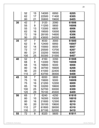
  • 29. 28 Dimensions and static and dynamic load capabilities of single–row deep groove ball bearings. Principal dimensions (mm) Basic load ratings(N) Designation d D B C 0C 10 19 5 1480 630 61800 26 8 4620 1960 6000 30 9 5070 2240 6200 35 11 8060 3750 6300 12 21 5 1430 695 61801 28 8 5070 2240 6001 32 10 6890 3100 6201 37 12 9750 4650 6301 15 24 5 1560 815 61802 32 9 5590 2500 6002 35 11 7800 3550 6202 42 13 11400 5400 6302 17 26 5 1680 930 61803 35 10 6050 2800 6003 40 12 9560 4500 6202 47 14 13500 6550 6303 62 17 22900 11800 6403 20 32 7 2700 1500 61804 42 8 7020 3400 16400 42 12 9360 4500 6004 47 14 12700 6200 6204 52 15 15900 7800 6304 72 19 30700 16600 6404 25 37 7 3120 1960 61805 47 8 7610 4000 16005 47 12 11200 5600 6005 A MEADinfo Publication Shinto Mathew
  • 30. 29 52 15 14000 6950 6205 62 17 22500 11400 6305 80 21 35800 19600 6405 30 42 7 3120 2080 61806 55 9 11200 5850 16006 55 13 13300 6800 6006 62 16 19500 10000 6206 72 19 28100 14600 6306 90 23 43600 24000 6406 35 47 7 4030 3000 61800 62 9 12400 6950 16007 62 14 15900 8500 6007 72 17 25500 13700 6207 80 21 33200 18000 6307 100 25 55300 31000 6407 40 52 7 4160 3350 61808 68 9 13300 7800 16008 68 15 16800 9300 6008 80 18 30700 16600 6208 90 23 41000 22400 6308 110 27 63700 36500 6408 45 58 7 6050 3800 61809 75 10 15600 9300 16009 75 16 21200 12200 6009 85 19 33200 18600 6209 100 25 52700 30000 6309 120 29 76100 45500 6409 50 65 7 6240 4250 61810 80 10 16300 10000 16010 80 16 21600 12300 6010 90 20 35100 19600 6210 110 27 61800 36000 6310 130 31 87100 52000 6410 55 72 9 8320 5600 61811 A MEADinfo Publication Shinto Mathew
  • 31. 30 90 11 19500 12200 16011 90 18 28100 17000 6011 100 21 43600 25000 6211 120 29 71500 41500 6311 140 33 99500 63000 6411 60 78 10 8710 6100 61812 95 11 19900 13200 16012 95 18 29600 18300 6012 110 22 47500 28000 6212 130 31 81900 48000 6312 150 35 108000 69500 6412 65 85 10 11700 8300 61813 100 11 21200 14600 16013 100 18 30700 19600 6013 120 23 55900 34000 6213 140 33 92300 56000 6313 160 37 119000 78000 6413 70 90 10 12100 9150 61814 110 13 28100 19000 16014 110 20 37700 24500 6014 125 24 61800 37500 6214 150 35 104000 63000 6314 180 42 143000 104000 6414 75 95 10 12500 9800 61815 115 13 28600 20000 10615 115 20 39700 26000 6015 130 25 66300 40500 6215 160 37 112000 72000 6315 190 45 153000 114000 6415 A MEADinfo Publication Shinto Mathew
  • 32. 31 Dynamic load capacity p P C L ⎟ ⎠ ⎞ ⎜ ⎝ ⎛ = A MEADinfo Publication Shinto Mathew
  • 33. 32 Selection of Taper Roller Bearings Y F F r a 5.0 = Where Y is the thrust factor Equivalent dynamic load for single row taper roller bearings is given by ( ) ( ) eFFwhenYFFP eFFwhenFP raar rar >+= ≤= 4.0 Dimensions, Dynamic capabilities and calculation factors for single row taper roller bearing d D B C Designation e Y 20 42 15 22900 32004X 0.37 1.6 47 15.25 26000 30204 0.35 1.7 52 16.25 31900 30304 0.30 2.0 52 72.25 41300 32304 0.30 2.0 25 47 15 25500 32005X 0.43 1.4 52 16.25 29200 30205 0.37 1.6 52 19.25 34100 32205B 0.57 1.05 52 22 44000 33205 0.35 1.7 62 18.25 41800 30305 0.30 2 62 18.25 35800 31305 0.83 0.72 62 25.25 56100 32305 0.30 2 30 55 17 33600 32006X 0.43 1.4 62 17.25 38000 30206 0.37 1.6 62 21.25 47300 32206 0.37 1.6 62 21.25 45700 32206B 0.57 1.05 A MEADinfo Publication Shinto Mathew
  • 34. 33 30 62 25 60500 33206 0.35 1.7 72 20.75 52800 30306 0.31 1.9 72 20.75 44600 31306 0.83 0.72 72 28.75 72100 32306 0.31 1.9 35 62 18 40200 32007X 0.46 1.3 72 18.25 48400 30207 0.37 1.6 72 24.25 61600 32207 0.37 1.6 72 24.25 57200 32207B 0.57 1.05 72 28 79200 33207 0.35 1.7 80 22.75 68200 30307 0.31 1.9 80 22.75 57200 31307 0.83 0.72 80 32.75 89700 32307 0.31 1.9 80 32.75 88000 32307B 0.54 1.1 40 68 19 49500 32008X 0.37 1.6 75 26 74800 33108 0.35 1.7 80 19.75 58300 30208 0.37 1.6 80 24.75 70400 32208 0.37 1.6 80 32 96800 33208 0.35 1.7 85 33 114000 T2EE040 0.35 1.7 90 25.25 80900 30308 0.35 1.7 90 25.25 69300 31308 0.83 1.72 90 35.25 110000 32308 0.35 1.7 45 75 20 55000 32009X 0.40 1.5 80 26 79200 33109 0.37 1.6 85 20.75 62700 30209 0.40 1.5 85 24.75 74800 32209 0.40 1.5 85 32 101000 33209 0.40 1.5 95 29 84200 T7FC045 0.88 0.68 95 36 140000 T2ED045 0.33 1.8 100 27.25 101000 30309 0.35 1.7 100 27.25 85800 31309 0.83 0.72 100 38.25 132000 32309 0.35 1.7 100 38.25 128000 32309B 0.54 1.1 50 80 20 57200 32010X 0.43 1.4 A MEADinfo Publication Shinto Mathew
  • 35. 34 50 80 24 64400 33010 0.31 1.9 85 26 80900 33110 0.40 1.5 90 21.75 70400 30210 0.43 1.4 90 24.75 76500 32210 0.43 1.4 90 32 108000 33210 0.40 1.5 100 36 145000 T2ED050 0.35 1.7 105 32 102000 T7FC050 0.88 0.68 110 29.25 117000 30310 0.35 1.7 110 29.25 99000 31310 0.83 0.72 110 42.25 161000 32310 0.35 1.7 110 42.25 151000 32310B 0.54 1.1 60 95 23 76500 32012X 0.43 1.4 95 27 85800 33012 0.33 1.8 100 30 110000 33112 0.40 1.5 110 23.75 91300 30212 0.40 1.5 110 29.75 119000 32212 0.40 1.5 110 38 157000 33212 0.40 1.5 115 39 157000 T5ED060 0.54 1.1 115 40 183000 T2EE060 0.33 1.8 125 37 145000 T7FC060 0.83 0.72 130 33.5 161000 30312 0.35 1.7 130 33.5 134000 31312 0.83 0.72 130 48.5 216000 32312 0.35 1.7 130 48.5 205000 32312B 0.54 1.1 70 110 25 95200 32014X 0.43 1.4 110 31 121000 33014 0.28 2.1 120 37 161000 33114 0.37 1.6 125 26.25 119000 30214 0.43 1.4 125 33.25 147000 32214 0.43 1.4 125 41 190000 33214 0.40 1.5 130 43 220000 T2ED070 0.33 1.8 140 39 168000 T7FC070 0.88 0.68 140 32 264000 T4FE070 0.44 1.35 150 38 209000 3014 0.35 1.7 A MEADinfo Publication Shinto Mathew
  • 36. 35 70 150 38 176000 31314 0.83 0.72 150 54 275000 32314 0.35 1.7 150 54 264000 32314B 0.54 1.1 80 125 29 128000 32016X 0.43 1.4 125 36 157000 33016 0.28 2.1 130 37 168000 33116 0.43 1.4 140 28.25 140000 30216 0.43 1.4 140 35.25 176000 32216 0.43 1.4 140 46 233000 33216 0.43 1.4 145 46 264000 T2ED080 0.31 1.9 170 42.5 255000 30316 0.35 1.7 170 42.5 212000 31316 0.83 0.72 170 61.5 358000 32316 0.35 1.7 170 61.5 336000 32316B 0.54 1.1 90 140 32 157000 32018X 0.43 1.4 140 39 205000 33018 0.27 2.2 150 45 238000 33118 0.40 1.5 155 46 270000 T2ED090 0.33 1.8 160 32.5 183000 30218 0.43 1.4 160 42.5 238000 32218 0.43 1.4 190 46.5 308000 30318 0.35 1.7 190 46.5 251000 31318 0.83 0.72 190 67.5 429000 32318 0.35 1.7 100 145 24 119000 T4CB100 0.48 1.25 150 32 161000 32020X 0.46 1.3 150 39 212000 33020 0.28 2.1 165 47 292000 T2EE100 0.31 1.9 180 37 233000 30220 0.43 1.4 180 49 297000 32220 0.43 1.4 180 63 402000 33220 0.40 1.5 215 51.5 380000 30320 0.35 1.7 215 56.5 352000 31320X 0.83 0.72 215 77.5 539000 32320 0.35 1.7 150 225 48 347000 32030X 0.46 1.3 A MEADinfo Publication Shinto Mathew
  • 37. 36 150 270 49 402000 30230 0.43 1.4 270 77 682000 32230 0.43 1.4 320 72 765000 30330 0.35 1.7 320 82 837000 31330X 0.83 0.72 200 280 51 446000 32940 0.40 1.5 310 70 704000 32040X 0.43 1.4 360 64 737000 30240 0.43 1.4 360 104 1140000 32240 0.40 1.5 300 420 76 990000 32960 0.40 1.5 A MEADinfo Publication Shinto Mathew
  • 38. 37 A MEADinfo Publication Shinto Mathew
  • 39. 38 Design for Cyclic Load and Speeds 3 3 ⎥ ⎦ ⎤ ⎢ ⎣ ⎡ Σ Σ = N BP Pe Bearing With a Probability of Survival Other Than 90 Percent b e e R R L L 1 90 90 1 log 1 log ⎥ ⎥ ⎥ ⎥ ⎥ ⎦ ⎤ ⎢ ⎢ ⎢ ⎢ ⎢ ⎣ ⎡ ⎟⎟ ⎠ ⎞ ⎜⎜ ⎝ ⎛ ⎟ ⎠ ⎞ ⎜ ⎝ ⎛ =⎟⎟ ⎠ ⎞ ⎜⎜ ⎝ ⎛ Where b = 1.17 A MEADinfo Publication Shinto Mathew
  • 40. 39 Sliding Contact Bearing Effect of Temperature on Viscosity A MEADinfo Publication Shinto Mathew
  • 41. 40 Hydrostatic Step Bearing The following notations are used in the analysis, W = Trust load 0R = outer radius of the shaft iR = inner radius of the shaft iP = supply of inlet pressure oP = outlet or atmospheric pressure 0h = fluid film thickness Q = flow of the lubricant μ = viscosity of the lubricant ⎟⎟ ⎠ ⎞ ⎜⎜ ⎝ ⎛ = i e i R R hP Q 0 3 0 log6μ π ⎥ ⎥ ⎥ ⎥ ⎥ ⎦ ⎤ ⎢ ⎢ ⎢ ⎢ ⎢ ⎣ ⎡ ⎟⎟ ⎠ ⎞ ⎜⎜ ⎝ ⎛ − = i e ii R R RRP W 0 22 0 log 2 π Energy Losses in Hydrostatic Thrust Bearing )10)(()( 6 0 − −= PPQkW ip pkW )( = power loss in pumping 0 44 0 2 6 )( 1005.58 1 )( h RRn kW i f − ⎥⎦ ⎤ ⎢⎣ ⎡ × = μ fkW )( = power loss due to friction A MEADinfo Publication Shinto Mathew
  • 42. 41 fpt kWkWkW )()()( += tkW )( = total power loss Reynold’s Equation ⎟ ⎠ ⎞ ⎜ ⎝ ⎛ ∂ ∂ =⎥ ⎦ ⎤ ⎢ ⎣ ⎡ ∂ ∂ ∂ ∂ +⎥ ⎦ ⎤ ⎢ ⎣ ⎡ ∂ ∂ ∂ ∂ x h U z p h zx p h x μ633 Raimondi and Boyd Method Dimensionless performance parameters for full journal bearings with side flow ⎟ ⎠ ⎞ ⎜ ⎝ ⎛ d l ε ⎟ ⎠ ⎞ ⎜ ⎝ ⎛ c h0 S φ f c r ⎟ ⎠ ⎞ ⎜ ⎝ ⎛ ⎟⎟ ⎠ ⎞ ⎜⎜ ⎝ ⎛ lrcn Q s ⎟⎟ ⎠ ⎞ ⎜⎜ ⎝ ⎛ Q Qs ⎟⎟ ⎠ ⎞ ⎜⎜ ⎝ ⎛ maxp p ∞ 0 1.0 ∞ 70.92 ∞ π 0 _ 0.1 0.9 0.240 69.10 4.80 3.03 0 0.826 0.2 0.8 0.123 67.26 2.57 2.83 0 0.814 0.4 0.6 0.0626 61.94 1.52 2.26 0 0.764 0.6 0.4 0.0389 54.31 1.20 1.56 0 0.667 0.8 0.2 0.021 42.22 0.961 0.760 0 0.495 0.9 0.1 0.0115 31.62 0.756 0.411 0 0.358 0.97 0.03 _ _ _ _ 0 _ 1.0 0 0 0 0 0 0 0 1 0 1.0 ∞ 85 ∞ π 0 _ 0.1 0.9 1.33 79.5 26.4 3.37 0.150 0.540 0.2 0.8 0.631 74.02 12.8 3.59 0.280 0.529 0.4 0.6 0.264 63.10 5.79 3.99 0.497 0.484 0.6 0.4 0.121 50.58 3.22 4.33 0.680 0.415 0.8 0.2 0.0446 36.24 1.70 4.62 0.842 0.313 0.9 0.1 0.0188 26.45 1.05 4.74 0.919 0.247 A MEADinfo Publication Shinto Mathew
  • 43. 42 0.97 0.03 0.00474 15.47 0.514 4.82 0.973 0.152 1.0 0 0 0 0 0 1.0 _ ½ 0 1.0 ∞ 88.5 ∞ π 0 _ 0.1 0.9 4.31 81.62 85.6 3.43 0.173 0.523 0.2 0.8 2.03 74.94 40.9 3.72 0.318 0.506 0.4 0.6 0.779 61.45 17.0 4.29 0.552 0.441 0.6 0.4 0.319 48.14 8.10 4.85 0.730 0.365 0.8 0.2 0.0923 33.31 3.26 5.41 0.874 0.267 0.9 0.1 0.0313 23.66 1.60 5.69 0.939 0.206 0.97 0.03 0.00609 13.75 0.610 5.88 0.980 0.126 1.0 0 0 0 0 _ 1.0 0 ¼ 0 1.0 ∞ 89.5 ∞ π 0 _ 0.1 0.9 16.2 82.31 322.0 3.45 0.180 0.515 0.2 0.8 7.57 75.18 153.0 3.76 0.330 0.489 0.4 0.6 2.83 60.86 61.1 4.37 0.567 0.415 0.6 0.4 1.07 46.72 26.7 4.99 0.746 0.334 0.8 0.2 0.261 31.04 8.8 5.60 0.884 0.240 0.9 0.1 0.0736 21.85 3.50 5.91 0.945 0.180 0.97 0.03 0.0101 12.22 0.922 6.12 0.984 0.108 1.0 0 0 0 0 _ 1.0 0 c = R-r Where c = radial clearance (mm) R = radius of bearing r = radius of journal c e =ε Where e =eccentricity ratio, ε = eccentricity ratio ⎟ ⎠ ⎞ ⎜ ⎝ ⎛ −= c h0 1ε Where 0h =film thickness A MEADinfo Publication Shinto Mathew
  • 44. 43 ⎟ ⎠ ⎞ ⎜ ⎝ ⎛ c h0 is called the minimum film thickness variable The Sommerfed number is given by p n c r S sμ 2 ⎟ ⎠ ⎞ ⎜ ⎝ ⎛ = Where sn =journal speed p = unit bearing pressure The Coefficient of Friction Variable (CFV) is given by f c r CFV ⎟ ⎠ ⎞ ⎜ ⎝ ⎛ =)( Where f is the coefficient of friction Frictional power 6 10 2 )( fWrn kW s f π = The Flow Variable (FV) is given by lrcn Q FV s =)( Where l = length of the bearing Q= flow of the lubricant Temperature Rise )( )(3.8 FV CFVp t =Δ 2 t TT iav Δ += A MEADinfo Publication Shinto Mathew
  • 45. 44 Bearing Design – Selection of Parameters A MEADinfo Publication Shinto Mathew
  • 46. 45 Spur Gears The pitch circle diameter is given by mzd =1 Centre to centre distance, 2 )( gpn zzm a + = Here transmission ratio g p p g n n z z i == Standard System of Gear Tooth Choice 1 (preferred) 1.00 5.00 1.25 6.0 1.50 8.00 2.00 10.00 2.5 12.00 3.00 16.00 4.0 20.00 Choice2 1.12 5.5 1.375 7.00 1.75 9.00 2.25 11.00 2.75 14.0 3.50 18.00 4.5 Addendum( )ah =(m) Dedendum ( )fh =1.25m Clearance(c) =0.25m Tooth thickness = 1.5708m Fillet radius = 0.4m A MEADinfo Publication Shinto Mathew
  • 47. 46 Force Analysis n kW Mt π2 )(1060 6 × = 1 2 d m p t t = αtantr PP = αcos t N P P = Number of Teeth α2min sin 2 =z Pressure angle ( )α 0 5.14 0 20 0 25 minz (Theoretical) 32 17 11 minz (Practical) 27 14 9 Face Width (3m)<b< (12m) In preliminary stages of gear design, the face width assumed as ten times of module. A MEADinfo Publication Shinto Mathew
  • 48. 47 Beam Strength of Gear Tooth YmbS bb σ= Values of the Lewis form factor Y for 200 full depth involute system z Y z Y z Y 15 0.289 27 0.348 55 0.415 16 0.295 28 0.352 60 0.421 17 0.302 29 0.355 65 0.425 18 0.308 30 0.358 70 0.429 19 0.314 32 0.364 75 0.433 20 0.320 33 0.367 80 0.436 21 0.326 35 0.373 90 0.442 22 0.330 37 0.380 100 0.446 23 0.333 39 0.386 150 0.458 24 0.337 40 0.389 200 0.463 25 0.340 45 0.399 300 0.471 26 0.344 50 0.408 Rack 0.484 A MEADinfo Publication Shinto Mathew
  • 49. 48 Effective Load on Gear Tooth (1)For ordinary and commercially cut gears made with form cutters with v<10m/s v Cv + = 3 3 (2) For actually hobbled and generated gears with v<20m/s, v Cv + = 6 6 (3) For precision gears with shaving, grinding and lapping operations and with v>20m/s, v Cv + = 6.5 6.5 The pitch line velocity is given by 3 1060 ' × = nd v π The effective load between two meshing teeth is given by v ts eff C PC P = n the final stages of gear design, when the gear dimensions are known, the errors specified and the quality of gears determined, the dynamic load is calculated by the equations derived by Prof. Spotts. The effective load is given by ( )dtseff PPCP += where dP is the dynamic load Depending upon the materials of the pinion and the gear, there are three equations for the dynamic load. (1) Steel Pinion with steel gear: ( )2 2 2 1 21 2530 rr rbrzen P pp d + = A MEADinfo Publication Shinto Mathew
  • 50. 49 (2) C.I Pinion with C.I gear: ( )2 2 2 1 21 3785 rr rbrzen P pp d + = (3) Steel Pinion with C.I Gear ( )2 2 2 1 21 92.03260 rr rbrzen P pp d + = e = sum of errors between two meshing teeth (mm) gp eee += where pe =error for pinion ge =error for gear Type of driven machines Source of power Electric motor Turbine/Multi cylinder engine Single-cylinder engine Generators-feeding mechanisms-belt conveyors- blowers-compressors-agitators and mixers 1.10 1.25 1.50 Machine tools-hoist and cranes-rotary drives-piston pumps-distribution pumps 1.25 1.50 1.75 Blanking and shearing presses -rolling mills-centrifuges-steel work machinery 1.75 2.00 2.25 A MEADinfo Publication Shinto Mathew
  • 51. 50 Estimation of Module Based on Beam Strength ( ) ( ) 31 6 3 1060 ⎟⎟ ⎟ ⎟ ⎟ ⎠ ⎞ ⎜⎜ ⎜ ⎜ ⎜ ⎝ ⎛ ⎪ ⎪ ⎭ ⎪⎪ ⎬ ⎫ ⎪ ⎪ ⎩ ⎪⎪ ⎨ ⎧ ⎟ ⎠ ⎞ ⎜ ⎝ ⎛ ⎟ ⎠ ⎞ ⎜ ⎝ ⎛ × = Y S m b znC fsCkW m ut v s π Wear Strength of Gear Tooth ( ) 4.1 11cossin 21 2 EE K c + = αασ A MEADinfo Publication Shinto Mathew
  • 52. 51 KbQdS pw 1 = pg g zz z Q − = 2 Expression for the load stress factor K can be simplified when all the gears are made of steel with a 200 pressure angle . in this special case, 2 21 207000 mmNEE == 0 20=α 2 ))(81.9(27.0 mmNBHNc =σ where BHN=Brinell Hardness Number. Therefore, 2 100 16.0 ⎟ ⎠ ⎞ ⎜ ⎝ ⎛ = BHN K Estimation of Module Based on Wear Strength ( ) ( ) 31 2 6 1060 ⎟ ⎟ ⎟ ⎟ ⎠ ⎞ ⎜ ⎜ ⎜ ⎜ ⎝ ⎛ ⎪ ⎪ ⎭ ⎪⎪ ⎬ ⎫ ⎪ ⎪ ⎩ ⎪⎪ ⎨ ⎧ ⎟ ⎠ ⎞ ⎜ ⎝ ⎛ × = QK m b Cnz fsCkW m vpp s π Gear Design for Maximum Power Transmitting Capacity dw PS 2= 2 w dt S PP == A MEADinfo Publication Shinto Mathew
  • 53. 52 Helical gears ψcos P Pn = ψcosmmn = nm = normal module m = transverse module ψtan p pa = α α ψ tan tan cos n = ψcos nzm d = ψcos2 )( 21 zzm a n + = p g g p z z i == ω ω Where i=speed ratio for helical gear Suffixes p and g refer to the pinion and gear respectively a is the centre to centre distance between two helical gears having 1z and 2z as the number of teeth. The normal pressure angle is usually 0 20 . Virtual number of teeth ψ3 1 cos z z = A MEADinfo Publication Shinto Mathew
  • 54. 53 Tooth proportions In helical gears, the normal module nm should be selected from standards. The first preference values of the normal module are nm (mm) 1, 1.25, 1.5, 2, 2.5,3,4,5,6,8 and10. The standard proportions of the addendum and dedendum are, Addendum na mh =)( Dedendum nf mh 25.1)( = Clearance nmc 25.0)( = Addendum circle diameter ad is given by ⎥ ⎦ ⎤ ⎢ ⎣ ⎡ += 2 cos ψ z md na Dedendum circle diameter fd is given by ⎥ ⎦ ⎤ ⎢ ⎣ ⎡ −= 5.2 cosψ z md nf ψ π sin nm b ≥ This is the minimum face width. Force Analysis =tp Tangential component =rp Radial component =ap Axial or thrust component ψα coscos nt pp = ψtanta pp = A MEADinfo Publication Shinto Mathew
  • 55. 54 ⎥ ⎦ ⎤ ⎢ ⎣ ⎡ = ψ α cos tan n tr pp d m p t t 2 = Beam strength of helical gears YmS bnb σ= Effective load on gear tooth n kW Mt π2 )(1060 6 × = d M P t t 2 = v ts eff C PC P = sC = service factor (from table) vC = velocity factor The velocity factor , v Cv + = 6.5 6.5 Dynamic load is given by A MEADinfo Publication Shinto Mathew
  • 56. 55 2 2 2 1 21 2530 rr rbrzen P pp d + = )coscos( ψαndtseff PPCP += )( fsPS effb = Wear strength of helical gears ψ2 cos KbQd S p w = 11 1 2 pg g zz z Q + = pg g zz z Q + = 2 for internal helical gear pg g zz z Q − = 2 4.1 11 cossin 21 2 ⎥ ⎦ ⎤ ⎢ ⎣ ⎡ + = EE K nnc αασ A MEADinfo Publication Shinto Mathew
  • 57. 56 =nα Normal pressure angle )20( 0 2 100 16.0 ⎟ ⎠ ⎞ ⎜ ⎝ ⎛ = BHN K )( fsPS effw = A MEADinfo Publication Shinto Mathew
  • 58. 57 Bevel Gears γcos2 D rb = γcos 1 z z = g p z z =γtan p g z z =Γtan 2 π γ =Γ+ The cone distance 0A is given by 22 0 22 ⎟⎟ ⎠ ⎞ ⎜⎜ ⎝ ⎛ +⎟⎟ ⎠ ⎞ ⎜⎜ ⎝ ⎛ = gp DD A Force Analysis ⎥ ⎦ ⎤ ⎢ ⎣ ⎡ −= 2 sin 2 γbD r p m Where mr = radius of the pinion at the mid point along the face width b = face width of the tooth A MEADinfo Publication Shinto Mathew
  • 59. 58 m t t r M P = αtants PP = Where tP = tangential or useful component which is perpendicular to the plane of the paper. sP = the separating force between the two meshing teeth γα γα sintan costan ta tr PP PP = = Beam Strength of Bevel Gears ⎥ ⎦ ⎤ ⎢ ⎣ ⎡ −= 0 1 A b YmbS bb σ Where bS beam strength of the tooth m = module at the large end of the tooth b = face width bσ = permissible bending stress ( 3utS ) Y = Lewis form factor based on formative number of teeth 0A = cone distance D M P t t 2 = face width of the bevel gear is generally taken as (10 m) or ( 30A ) whichever is smaller A MEADinfo Publication Shinto Mathew
  • 60. 59 ∴b = (10 m) or ( )30A (Whichever is smaller) WEAR STRENGTH OF BEVEL GEARS Buckingham’s equation KbQdS pw 1 = Where wS = wear strength b = face width of gears Q = ratio factors 1 pd = pitch circle diameter of the formative pinion K = material constant bp rd 21 = γcos 75.0 KbQD S p w = (Buckingham’s equation) γtan 2 pg g zz z Q + = 4.1 11 cossin2 ⎥ ⎥ ⎦ ⎤ ⎢ ⎢ ⎣ ⎡ + = gp c EE K αασ When pinion as well as the gear is made of steel with 0 20 pressure angle, the value of K is given by 2 100 16.0 ⎟ ⎠ ⎞ ⎜ ⎝ ⎛ = BHN K A MEADinfo Publication Shinto Mathew
  • 61. 60 EFFECTIVE LOAD ON GEAR TOOTH n kW Mt π2 )(1060 6 × = D M P t t 2 = v ts eff C PC P = sC = service factor (from table) Type of driven machines Source of power Electric motor Turbine/Multi cylinder engine Single-cylinder engine Generators-feeding mechanisms-belt conveyors- blowers-compressors-agitators and mixers 1.10 1.25 1.50 Machine tools-hoist and cranes-rotary drives-piston pumps-distribution pumps 1.25 1.50 1.75 Blanking and shearing presses -rolling mills-centrifuges-steel work machinery 1.75 2.00 2.25 vC = velocity factor The velocity factor for cut teeth is given by A MEADinfo Publication Shinto Mathew
  • 62. 61 v Cv + = 6 6 For general teeth, v Cv + = 6.5 6.5 Dynamic load is given by 2 2 2 1 21 1 2530 rr rrbzen P pp d + 21,rr Radii of the pinion and gear respectively 1 b Axial width of the gear blank ⎥ ⎦ ⎤ ⎢ ⎣ ⎡ −= 2 sin 2 1 γbD r p ⎥ ⎦ ⎤ ⎢ ⎣ ⎡ −= 2 cos 2 2 γbD r g )( dtseff PPCP += Stress in gear tooth due to bending )( fsPS effb = Stress in gear tooth due to pitting )( fsPS effw = A MEADinfo Publication Shinto Mathew
  • 63. 62 Worm Gears Notations:- 1z = number of starts on the worm 2z = number of teeth on the worm wheel q = diametral quotient m = module 1d = pitch circle diameter of the worm 1ad = outer diameter of the worm 2ad = outer diameter of the worm wheel 2d = pitch circle diameter of the worm wheel l = lead of the worm xp = axial pitch of the worm a = the centre distance i = the speed ratio. F = the effective face width rl = the length of the root of the worm gear teeth. Proportions of Worm Gears A MEADinfo Publication Shinto Mathew
  • 64. 63 m d q 1 = 1zpl x= 22 mzd = mp x π= 1mzl π= )( 2 1 2zqma += A MEADinfo Publication Shinto Mathew
  • 65. 64 1 2 z z i = )1(2 += qmF ⎟⎟ ⎠ ⎞ ⎜⎜ ⎝ ⎛ + += − cd F cdl a ar 2 sin)2( 1 1 1 Force Analysis tP )( 1 = tangential component on the worm aP )( 1 = axial component on the worm rP )( 1 = radial component on the worm 1 1 2 )( d M P t t = ( ) ( )γμγα γμγα cossincos sincoscos )()( 11 + − ×= ta PP )cossin(cos sin )()( 11 γμγα α + ×= tr PP Friction in worm gears sv = rubbing velocity 1v = pitch line velocity of the worm 2v = pitch line velocity of the worm wheel )1000)(60( 11 1 nd v π = γ π cos)60000( 11nd vs = ( ) )cot( tancos γμα γμα η + − = cas A MEADinfo Publication Shinto Mathew
  • 66. 65 Strength Rating Of Worm Gears γ γ cos65.17)( cos65.17)( 2222 2111 dmlSXM dmlSXM rbbt rbbt = = 1)( tM , 2)( tM = permissible torque on the worm wheel 1bX , 2bX = speed factors for the strength of worm and worm wheel 1bS , 2bS = bending stress factors for worm and worm wheel A MEADinfo Publication Shinto Mathew
  • 67. 66 m = module rl = the length of the root of the worm gear teeth. 2d = pitch circle diameter of the worm wheel γ = lead angle of the worm Power transmitting capacity of the worm gear based on the beam strength is given by 6 1060 2 × = tnM kW π Where )( tM is the lower value between 1)( tM and 2)( tM . A MEADinfo Publication Shinto Mathew
  • 68. 67 Wear Rating of Worm Gears mdYSXM mdYSXM Zcct Zcct 8.1 2224 8.1 2113 )(64.18)( )(64.18)( = = 3)( tM , 4)( tM = permissible torque on the worm wheel 1cX , 2cX = speed factors for the strength of worm and worm wheel 1cS , 2cS = surface stress factors of the worm and worm wheel zY = zone factor Thermal Considerations kWH g )1(1000 η−= Where gH = rate heat generation A MEADinfo Publication Shinto Mathew
  • 69. 68 η = efficiency of the of the worm gear (fraction) kW = power transmitted by the gears AttkHd )( 0−= Where dH = rate of heat dissipation k = overall heat transfer coefficient of housing walls( )CmW 02 t = temperature of the lubrication oil. ( C0 ) 0t = temperature of the surrounding air ( C0 ) A = effective surface area of housing kA kW tt Attk kW )1(1000 )1(1000 )( 0 0 η η − += − − = A MEADinfo Publication Shinto Mathew