SlideShare a Scribd company logo
4
Most read
8
Most read
9
Most read
1
LABORATORY MANUAL OF EEC456 & EEE454
Prepared at Ashoka Institute of Technology & Management, Aktha, Sarnath, Varanasi, U.P.
With
Participation & Valuable Contributions from
Er. Anupam Kumar, ECE, HOD & Assistant Professor, AITM
(anupamkumarmtec@gmail.com)
Department of Electronics & Communication Engineering
1 To study 8085 microprocessor System
2 To study 8086 microprocessor System
3 To develop and run a program for finding out the largest/smallest number from a given set of
numbers.
4 To develop and run a program for arranging in ascending/descending order of a set of numbers
5 To develop and run a programme to compute square root of a given number
6 To perform multiplication/division of given numbers
7 To perform floating point mathematical operations (addition, subtraction, multiplication and
division)
8 To obtain interfacing of keyboard controller
9 To perform interfacing of DMA controller
10 To obtain interfacing of RAM chip to 8085/8086 based system
Textbook: Lab Manual EEC456
Additional Readings:
1. Ramesh Gaonkar,”Microprocessor Architecture, Programming, and Applications with the
8051, 5th
Edition, Penram International Publication (India) Pvt. Ltd.
2. Douglas V. Hail,” Microprocessor and Interfacing,”2nd
Edition,TMH,2006
3. User’s Guide (XPO 85/SW), ANSHUMAN Tech Pvt. Ltd.
Course Code: E E C 4 5 6
Course
Title: Microprocessors Laboratory
FACULTY NAME MR. ANUPAM KUMAR
Attendance
Weightages
CA MTE ETE
0 0 0
2
3
 QUICK STEPS TO LEARN OPERATION WITH KIT
Step I:-Procedure to operate kit using assembly language program.
Do connections as per your figure
Switch ON power supply (i.e. SMPS (Switched mode power supply)
ANSHUMAN will be display on display board.
Press ENTER key
Go to command mode
COMMAND=
Press E
EXPAND=
Press A
2 PASS ASSEMBLER?
Press ENTER key 3 times
Files EXIST?
Press ‘N’ (No)
ARE YOU SURE?
Press ENTER KEY
C=
Press ‘W’
0001 ORG 6000H (Write your program here)
0002 MVI A, 22H
0003 MVI B, 33H
0004 ADD B
0005 RST 1
Press Ctrl key+ C
C=
4
Press ‘A’ Key
Will show message save code at DSTN? Y/N
Press ‘Y’ (Yes)
C=
Press ‘ESC’ two times
COMMAND= (Go to command mode)
Execution of the program
Press ‘G’
Go to?
Press ENTER key 2 times
BURST ADDR
GIVE 6000H
Press ENTER Key
COMMAND= (Go to command mode)
Checking contents of registers
Press ‘S’
SUBSTUT?
Press ENTER key
MEMORY
Press ‘any key’ other than ‘Enter Key’ 2 times
IO REGISTER (GIVE THE NAME)
Press ENTER key
NAME
5
A=55(Result i.e. 22+33=55)
 NOTE: - On Pressing Enter subsequently all registers contents will display.
 PROCEDURE TO OPERATE KIT USING DISASSEMBLER
Press E
EXPAND
Press U
Press ENTER key 3 times
STRT
Give 6000
Press ENTER
END
Give 6009
Press ENTER
DSTN
Give 6000
Press ENTER
PRINTER?
Press ‘’CTR+C’’ step by step
ABBREVIATIONS & DESCRIPTIONS:-
 S (SUBSTUT)-Use substitute command to enter program.
 Ctr+U- You can check data previously entered by pressing Ctrl-U key.
 ESC (Display COMMAND) - Come to command mode.
 CR (MEMORY) - Display first mode: Memory.
 BURST- Use to BURST Mode.
 ADDR- Asks the program address.
 COMMAND- Comes back to command mode.
 REGISTER- Display next mode: Register.
 Any key IO- Displays next mode: Input/output port.
6
APPARATUS
8085 TRAINER KIT & 8085 SIMULATOR SOFTWARE
7
INTERFACING STUDY CARDS
8
OTHERS EXPERIMENTS
AIM: Interfacing and control of stepper motor using 8085 microprocessor.
Apparatus required: stepper motor (12 volts)
SAMPLE PROGRAM: Interface a Stepper Motor to the 8085 microprocessor system and
write an 8085 assembly language program to control the Stepper Motor.
Block Diagram:-
SOFTWARE FOR STEPPER MOTOR CONTROL:
As port A is used as an output port, control word for 8255 is 80H. Stepper Motor Control
Program: 6000H Excite code DB 03H, 06H, 09H, and OCH: This is the code sequence for
clockwise rotation Subroutine to rotate a stepper motor clockwise by 360° - Set the counts:
MVI C, 32H: Set repetition count to 50ıο
START: MVI B, 04H: Counts excitation sequence
LXI H, 6000H: Initialize pointer
BACK1: MOV A, M: Get the Excite code
OUT PORTA: Send Excite code
CALL DELAY: Wait
INX H: Increment pointer
DCR B: Repeat 4 times JNZ BACK l
9
Delay subroutine:
Delay: LXI D, Count
Back: DCX D
MOV A, D
ORA E
JNZ Back RET
FLOWCHARTS: Stepper motor subroutine
Conclusion: - A stepper motor is a digital motor. It can be driven by digital signal. Fig.
shows the typical 2 phase motor rated 12V /0.67 A/ph interfaced with the 8085
microprocessor system using 8255. Motor shown in the circuit has two phases, with center-
tap winding. The center taps of these windings are connected to the 12V supply. Due to this,
motor can be excited by grounding four terminals of the two windings. Motor can be rotated
in steps by giving proper excitation sequence to these windings. The lower nibble of port A
of the 8255 is used to generate excitation signals in the proper sequence. These excitation
signals are buffered using driver transistors. The transistors are selected such that they can
source rated current for the windings. Motor is rotated by 1.80 per excitation.
EXPERIMENT
AIM Generation of delay in binary counting using 8085 microprocessor.
SAMPLE PROGRAM Write a program for displaying binary up counter. Counter should
count numbers from 00 to FFH and it should increment after every 0.5 sec.
10
Source Program:
LXI SP, 27FFH: Initialize stack pointer
MVI C, OOH: Initialize counter
BACK: CALL Display: Call display subroutine
CALL Delay: Call delay subroutine
INR C: Increment counter
MOV A, C
CPI OOH: Check counter is > FFH
JNZ BACK: If not, repeat
HLT: Stop
Delay Subroutine: Delay: LXI B, count: Initialize count
BACK: DCX D: Decrement count
MOV A, E
ORA D: Logically OR D and E
JNZ BACK: If result is not 0 repeat
RET: Return to main program
Conclusion: Assume operating frequency of 8085 equal to 2MHz. Display routine is
available.
11
PHOTO GALLARY: STUDENTS PERFORM EXPERIMENTS ON KIT & SIMULATOR
12
13
LAB ASSIGNMENT
1. (A) Addition of two nos. is stored in location 20C0 & 20C1 respective & result is
stored in 20C2. (B) Subtraction of two no.
2. Write a program using 8085 microprocessor for Decimal, Hexadecimal addition and
subtraction of two numbers.
3. To perform multiplication and division of two 8 bit numbers using 8085.
4. To find the largest and smallest number in an array of data using 8085 instruction
set.
5. To write a program to arrange an array of data in ascending & descending order.
6. To convert given Hexadecimal number into its equivalent ASCII number & vice
versa using 8085.

More Related Content

PPTX
Bus aribration
PPTX
8255 Programmble Peripheral Interface
PPTX
MULTIPLEXER
PPT
Digital Logic Design
PPTX
Latches and flip flop
PPTX
8086 Micro-processor and MDA 8086 Trainer Kit
PPTX
Lcd interfaing using 8051 and assambly language programming
Bus aribration
8255 Programmble Peripheral Interface
MULTIPLEXER
Digital Logic Design
Latches and flip flop
8086 Micro-processor and MDA 8086 Trainer Kit
Lcd interfaing using 8051 and assambly language programming

What's hot (20)

DOCX
Lambda design rule
PDF
8051 interfacing
PPT
Programmable Logic Devices Plds
PPT
basic logic gates
PPT
Memory organization of 8051
PPTX
Ipv4 and Ipv6
PDF
8086 microprocessor lab manual
PPTX
TCP and UDP
PPTX
Direct memory access (dma)
PPTX
Raspberry Pi (Introduction)
PPT
Sequential circuits
PDF
Designing of 8 BIT Arithmetic and Logical Unit and implementing on Xilinx Ver...
PPTX
Osi model
PPT
Adc interfacing
PDF
Cs8591 Computer Networks
PPTX
Combinational circuits
PDF
8051 microcontroller
ODP
axi protocol
PPTX
Application layer protocols
PPT
OSI Model
Lambda design rule
8051 interfacing
Programmable Logic Devices Plds
basic logic gates
Memory organization of 8051
Ipv4 and Ipv6
8086 microprocessor lab manual
TCP and UDP
Direct memory access (dma)
Raspberry Pi (Introduction)
Sequential circuits
Designing of 8 BIT Arithmetic and Logical Unit and implementing on Xilinx Ver...
Osi model
Adc interfacing
Cs8591 Computer Networks
Combinational circuits
8051 microcontroller
axi protocol
Application layer protocols
OSI Model
Ad

Viewers also liked (20)

PDF
Mp lab manual
PDF
8085 microprocessor lab manual
PDF
Microprocessor lab
PDF
8080 8085 assembly language_programming manual programando
PDF
Microprocessor and Interfacing Lab Notes - Akshansh
PDF
Anshuman Tech Private Limited, Pune, Training Equipment
PDF
Micro Processor Lab Manual!
PDF
Microprocessor lab manual
PDF
Micro prointronprog
DOCX
8085 manual NCIT SAROZ BISTA SIR
PDF
computer architecture lab manual
PDF
Mp &mc programs
PDF
Microprocessor lab
PPTX
Micro Processor Mini Project,Electronic Quiz Table
PPT
Assemblylanguageprogrammingof8085 100523023329-phpapp02
PDF
8085 lab
PPT
8085 instruction-set new
PPT
Unit – 2
Mp lab manual
8085 microprocessor lab manual
Microprocessor lab
8080 8085 assembly language_programming manual programando
Microprocessor and Interfacing Lab Notes - Akshansh
Anshuman Tech Private Limited, Pune, Training Equipment
Micro Processor Lab Manual!
Microprocessor lab manual
Micro prointronprog
8085 manual NCIT SAROZ BISTA SIR
computer architecture lab manual
Mp &mc programs
Microprocessor lab
Micro Processor Mini Project,Electronic Quiz Table
Assemblylanguageprogrammingof8085 100523023329-phpapp02
8085 lab
8085 instruction-set new
Unit – 2
Ad

Similar to Microprocessor lab manual (20)

PDF
Lab manual mp
PDF
Real Time Embedded System
PDF
Microprocessor and Microcontroller Lab Manual!
PDF
Switch Control and Time Delay - Keypad
DOCX
Introduction to 8085 & it's description(includes basic lab experiments)
PDF
EE2356 Microprocessor and Microcontroller Lab Manuel
PDF
Microprocessor Lab Manual by Er. Swapnil V. Kaware
PDF
Analog to Digital Converter
DOCX
Temperature Controlled Fan Report
DOCX
Mpi lab manual eee
PPT
Assembly Language Programming Of 8085
DOCX
Mechatronics Manual.docx
PDF
Pf700 energy savings_lab
PPTX
PDF
Diljit.pdf
PPT
1. Instructionset.pptfor engineering student
PPT
Malp edusat
PPTX
Arduino Interfacing with different sensors and motor
PDF
Microprocessorlabmanual ee0310
DOC
180410227 ae2406-lab-manual-doc
Lab manual mp
Real Time Embedded System
Microprocessor and Microcontroller Lab Manual!
Switch Control and Time Delay - Keypad
Introduction to 8085 & it's description(includes basic lab experiments)
EE2356 Microprocessor and Microcontroller Lab Manuel
Microprocessor Lab Manual by Er. Swapnil V. Kaware
Analog to Digital Converter
Temperature Controlled Fan Report
Mpi lab manual eee
Assembly Language Programming Of 8085
Mechatronics Manual.docx
Pf700 energy savings_lab
Diljit.pdf
1. Instructionset.pptfor engineering student
Malp edusat
Arduino Interfacing with different sensors and motor
Microprocessorlabmanual ee0310
180410227 ae2406-lab-manual-doc

More from ASHOKA INSTITUTE OF TECHNOLOGY & MANAGEMENT,VARANASI,U.P. (20)

PDF
Some advanced instructions of the 8085 microprocessors
PDF
Introduction to-microprocessors-unit-1
PDF
Microprocessor paper 4 with solutions
PDF
Microprocessor paper 3 with solutions
Some advanced instructions of the 8085 microprocessors
Introduction to-microprocessors-unit-1
Microprocessor paper 4 with solutions
Microprocessor paper 3 with solutions

Recently uploaded (20)

PPTX
Lecture Notes Electrical Wiring System Components
DOCX
573137875-Attendance-Management-System-original
PDF
Mitigating Risks through Effective Management for Enhancing Organizational Pe...
PPTX
M Tech Sem 1 Civil Engineering Environmental Sciences.pptx
PPTX
MCN 401 KTU-2019-PPE KITS-MODULE 2.pptx
PPTX
CYBER-CRIMES AND SECURITY A guide to understanding
PDF
Mohammad Mahdi Farshadian CV - Prospective PhD Student 2026
PDF
BMEC211 - INTRODUCTION TO MECHATRONICS-1.pdf
PDF
Embodied AI: Ushering in the Next Era of Intelligent Systems
PPTX
Geodesy 1.pptx...............................................
PDF
Digital Logic Computer Design lecture notes
PDF
keyrequirementskkkkkkkkkkkkkkkkkkkkkkkkkkkkkkkkkkkkk
PPTX
Infosys Presentation by1.Riyan Bagwan 2.Samadhan Naiknavare 3.Gaurav Shinde 4...
PDF
PPT on Performance Review to get promotions
PPTX
Welding lecture in detail for understanding
PPT
Project quality management in manufacturing
PPTX
Internet of Things (IOT) - A guide to understanding
PPTX
bas. eng. economics group 4 presentation 1.pptx
PPTX
IOT PPTs Week 10 Lecture Material.pptx of NPTEL Smart Cities contd
PPTX
Construction Project Organization Group 2.pptx
Lecture Notes Electrical Wiring System Components
573137875-Attendance-Management-System-original
Mitigating Risks through Effective Management for Enhancing Organizational Pe...
M Tech Sem 1 Civil Engineering Environmental Sciences.pptx
MCN 401 KTU-2019-PPE KITS-MODULE 2.pptx
CYBER-CRIMES AND SECURITY A guide to understanding
Mohammad Mahdi Farshadian CV - Prospective PhD Student 2026
BMEC211 - INTRODUCTION TO MECHATRONICS-1.pdf
Embodied AI: Ushering in the Next Era of Intelligent Systems
Geodesy 1.pptx...............................................
Digital Logic Computer Design lecture notes
keyrequirementskkkkkkkkkkkkkkkkkkkkkkkkkkkkkkkkkkkkk
Infosys Presentation by1.Riyan Bagwan 2.Samadhan Naiknavare 3.Gaurav Shinde 4...
PPT on Performance Review to get promotions
Welding lecture in detail for understanding
Project quality management in manufacturing
Internet of Things (IOT) - A guide to understanding
bas. eng. economics group 4 presentation 1.pptx
IOT PPTs Week 10 Lecture Material.pptx of NPTEL Smart Cities contd
Construction Project Organization Group 2.pptx

Microprocessor lab manual

  • 1. 1 LABORATORY MANUAL OF EEC456 & EEE454 Prepared at Ashoka Institute of Technology & Management, Aktha, Sarnath, Varanasi, U.P. With Participation & Valuable Contributions from Er. Anupam Kumar, ECE, HOD & Assistant Professor, AITM (anupamkumarmtec@gmail.com) Department of Electronics & Communication Engineering 1 To study 8085 microprocessor System 2 To study 8086 microprocessor System 3 To develop and run a program for finding out the largest/smallest number from a given set of numbers. 4 To develop and run a program for arranging in ascending/descending order of a set of numbers 5 To develop and run a programme to compute square root of a given number 6 To perform multiplication/division of given numbers 7 To perform floating point mathematical operations (addition, subtraction, multiplication and division) 8 To obtain interfacing of keyboard controller 9 To perform interfacing of DMA controller 10 To obtain interfacing of RAM chip to 8085/8086 based system Textbook: Lab Manual EEC456 Additional Readings: 1. Ramesh Gaonkar,”Microprocessor Architecture, Programming, and Applications with the 8051, 5th Edition, Penram International Publication (India) Pvt. Ltd. 2. Douglas V. Hail,” Microprocessor and Interfacing,”2nd Edition,TMH,2006 3. User’s Guide (XPO 85/SW), ANSHUMAN Tech Pvt. Ltd. Course Code: E E C 4 5 6 Course Title: Microprocessors Laboratory FACULTY NAME MR. ANUPAM KUMAR Attendance Weightages CA MTE ETE 0 0 0
  • 2. 2
  • 3. 3  QUICK STEPS TO LEARN OPERATION WITH KIT Step I:-Procedure to operate kit using assembly language program. Do connections as per your figure Switch ON power supply (i.e. SMPS (Switched mode power supply) ANSHUMAN will be display on display board. Press ENTER key Go to command mode COMMAND= Press E EXPAND= Press A 2 PASS ASSEMBLER? Press ENTER key 3 times Files EXIST? Press ‘N’ (No) ARE YOU SURE? Press ENTER KEY C= Press ‘W’ 0001 ORG 6000H (Write your program here) 0002 MVI A, 22H 0003 MVI B, 33H 0004 ADD B 0005 RST 1 Press Ctrl key+ C C=
  • 4. 4 Press ‘A’ Key Will show message save code at DSTN? Y/N Press ‘Y’ (Yes) C= Press ‘ESC’ two times COMMAND= (Go to command mode) Execution of the program Press ‘G’ Go to? Press ENTER key 2 times BURST ADDR GIVE 6000H Press ENTER Key COMMAND= (Go to command mode) Checking contents of registers Press ‘S’ SUBSTUT? Press ENTER key MEMORY Press ‘any key’ other than ‘Enter Key’ 2 times IO REGISTER (GIVE THE NAME) Press ENTER key NAME
  • 5. 5 A=55(Result i.e. 22+33=55)  NOTE: - On Pressing Enter subsequently all registers contents will display.  PROCEDURE TO OPERATE KIT USING DISASSEMBLER Press E EXPAND Press U Press ENTER key 3 times STRT Give 6000 Press ENTER END Give 6009 Press ENTER DSTN Give 6000 Press ENTER PRINTER? Press ‘’CTR+C’’ step by step ABBREVIATIONS & DESCRIPTIONS:-  S (SUBSTUT)-Use substitute command to enter program.  Ctr+U- You can check data previously entered by pressing Ctrl-U key.  ESC (Display COMMAND) - Come to command mode.  CR (MEMORY) - Display first mode: Memory.  BURST- Use to BURST Mode.  ADDR- Asks the program address.  COMMAND- Comes back to command mode.  REGISTER- Display next mode: Register.  Any key IO- Displays next mode: Input/output port.
  • 6. 6 APPARATUS 8085 TRAINER KIT & 8085 SIMULATOR SOFTWARE
  • 8. 8 OTHERS EXPERIMENTS AIM: Interfacing and control of stepper motor using 8085 microprocessor. Apparatus required: stepper motor (12 volts) SAMPLE PROGRAM: Interface a Stepper Motor to the 8085 microprocessor system and write an 8085 assembly language program to control the Stepper Motor. Block Diagram:- SOFTWARE FOR STEPPER MOTOR CONTROL: As port A is used as an output port, control word for 8255 is 80H. Stepper Motor Control Program: 6000H Excite code DB 03H, 06H, 09H, and OCH: This is the code sequence for clockwise rotation Subroutine to rotate a stepper motor clockwise by 360° - Set the counts: MVI C, 32H: Set repetition count to 50ıο START: MVI B, 04H: Counts excitation sequence LXI H, 6000H: Initialize pointer BACK1: MOV A, M: Get the Excite code OUT PORTA: Send Excite code CALL DELAY: Wait INX H: Increment pointer DCR B: Repeat 4 times JNZ BACK l
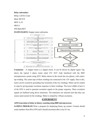
  • 9. 9 Delay subroutine: Delay: LXI D, Count Back: DCX D MOV A, D ORA E JNZ Back RET FLOWCHARTS: Stepper motor subroutine Conclusion: - A stepper motor is a digital motor. It can be driven by digital signal. Fig. shows the typical 2 phase motor rated 12V /0.67 A/ph interfaced with the 8085 microprocessor system using 8255. Motor shown in the circuit has two phases, with center- tap winding. The center taps of these windings are connected to the 12V supply. Due to this, motor can be excited by grounding four terminals of the two windings. Motor can be rotated in steps by giving proper excitation sequence to these windings. The lower nibble of port A of the 8255 is used to generate excitation signals in the proper sequence. These excitation signals are buffered using driver transistors. The transistors are selected such that they can source rated current for the windings. Motor is rotated by 1.80 per excitation. EXPERIMENT AIM Generation of delay in binary counting using 8085 microprocessor. SAMPLE PROGRAM Write a program for displaying binary up counter. Counter should count numbers from 00 to FFH and it should increment after every 0.5 sec.
  • 10. 10 Source Program: LXI SP, 27FFH: Initialize stack pointer MVI C, OOH: Initialize counter BACK: CALL Display: Call display subroutine CALL Delay: Call delay subroutine INR C: Increment counter MOV A, C CPI OOH: Check counter is > FFH JNZ BACK: If not, repeat HLT: Stop Delay Subroutine: Delay: LXI B, count: Initialize count BACK: DCX D: Decrement count MOV A, E ORA D: Logically OR D and E JNZ BACK: If result is not 0 repeat RET: Return to main program Conclusion: Assume operating frequency of 8085 equal to 2MHz. Display routine is available.
  • 11. 11 PHOTO GALLARY: STUDENTS PERFORM EXPERIMENTS ON KIT & SIMULATOR
  • 12. 12
  • 13. 13 LAB ASSIGNMENT 1. (A) Addition of two nos. is stored in location 20C0 & 20C1 respective & result is stored in 20C2. (B) Subtraction of two no. 2. Write a program using 8085 microprocessor for Decimal, Hexadecimal addition and subtraction of two numbers. 3. To perform multiplication and division of two 8 bit numbers using 8085. 4. To find the largest and smallest number in an array of data using 8085 instruction set. 5. To write a program to arrange an array of data in ascending & descending order. 6. To convert given Hexadecimal number into its equivalent ASCII number & vice versa using 8085.