Password based door lock system using 8051 microcontroller final report
Download as DOCX, PDF82 likes57,114 views

This document describes a password-based door lock system using an 8051 microcontroller. The system uses a keypad to enter a password, which is compared to a predefined password stored in the microcontroller's memory. If the entered password matches, the microcontroller will open the door by activating a motor. If an incorrect password is entered more than three times, an alarm will sound. The system is designed to only grant access to those who know the correct password, while denying access and potentially alerting others for incorrect password attempts.


![while(!col2);
return key;
}
if(!col3)
{
key = k+2;
while(!col3);
return key;
}
j++;
}
k+=3;
keyport |= 0x80>>i;
delayms(10);
}
return FALSE;
}
unsigned char translate(unsigned char keyval)
{ if(keyval<10)
return keyval+'
else if(keyval==10)
return 'x';
else if(keyval==11)
return '0';
else if(keyval==12)
return 'e';
}
LCD program:
#include "lcd.h"
#include "delay.h"
#include <REG2051.H>
unsigned char codelockicon[]={0xe, 0xa, 0x1f, 0x1f, 0x1b, 0x1b, 0xe, 0x0};
unsigned char codeunlockicon[]={0xe, 0x2, 0x1f, 0x1f, 0x1b, 0x1b, 0xe, 0x0};
unsigned char codeex[]={0x1f, 0x1b, 0x1b, 0x1b, 0x1b, 0x1f, 0x1b, 0x1f};
unsigned char codeok[]={0x0, 0x1, 0x3, 0x16, 0x1c, 0x8, 0x0, 0x0};
void lcd_reset()
{ lcd_port= 0xFF;
delayms(20);
lcd_port= 0x03+LCD_EN;
lcd_port = 0x03;](https://image.slidesharecdn.com/passwordbaseddoorlocksystemusing8051microcontrollerfinalreport-150418010421-conversion-gate02/85/Password-based-door-lock-system-using-8051-microcontroller-final-report-11-320.jpg)
![delayms(10);
lcd_port= 0x03+LCD_EN;
lcd_port= 0x03;
delayms(1);
lcd_port= 0x03+LCD_EN;
lcd_port= 0x03;
delayms(1);
lcd_port= 0x02+LCD_EN;
lcd_port= 0x02;
delayms(1);
}
void lcd_init ()
{ unsigned char i;
lcd_reset();
lcd_cmd(LCD_SETFUNCTION);// 4-bit mode - 1 line - 5x7 font.
lcd_cmd(LCD_SETVISIBLE+0x04); // Display no cursor - no blink.
lcd_cmd(LCD_SETMODE+0x02); // Automatic Increment - No Display shift.
lcd_cmd(LCD_SETCGADDR);
for(i=0;i<8;i++)
lcd_data(lockicon[i]); 27](https://image.slidesharecdn.com/passwordbaseddoorlocksystemusing8051microcontrollerfinalreport-150418010421-conversion-gate02/85/Password-based-door-lock-system-using-8051-microcontroller-final-report-12-320.jpg)
![for(i=0;i<8;i++)
lcd_data(unlockicon[i]);
for(i=0;i<8;i++)
lcd_data(ex[i]);
for(i=0;i<8;i++)
lcd_data(for(i=0;i<8;i++)
lcd_data(unlockicon[i]);
for(i=0;i<8;i++)
lcd_data(ex[i]);
for(i=0;i<8;i++)
lcd_data(ok[i]);
lcd_cmd(LCD_SETDDADDR); // Address DDRAM with 0 offset 80h.
}
void lcd_cmd (char cmd)
{ lcd_port= ((cmd >> 4) & 0x0F)|LCD_EN;
lcd_port= ((cmd >> 4) & 0x0F);
lcd_port= (cmd & 0x0F)|LCD_EN;
lcd_port= (cmd & 0x0F);
delayus(200);
delayus(200);
}
void lcd_data (unsigned char dat)
{ lcd_port= (((dat >> 4) & 0x0F)|LCD_EN|LCD_RS);
lcd_port= (((dat >> 4) & 0x0F)|LCD_RS);
lcd_port= ((dat & 0x0F)|LCD_EN|LCD_RS); lcd_port= ((dat &
0x0F)|LCD_RS);
delayus(200);
delayus(200);
}
void lcd_str(unsigned char *str)
{ while(*str){
lcd_data(*str++);
}
}
Lock program:
#include "keypad.h"
#include "lcd.h"
#include "delay.h"
#include "lock.h"
unsigned char codemasterlock[10]="1234567890", defaultulock[5]="54321";
unsigned char userlock[5], input[10];
extern bit newlock;
bit check(unsigned char *first, unsigned char *second, unsigned char len)](https://image.slidesharecdn.com/passwordbaseddoorlocksystemusing8051microcontrollerfinalreport-150418010421-conversion-gate02/85/Password-based-door-lock-system-using-8051-microcontroller-final-report-13-320.jpg)

![while(1){
while(!(key=getkey()));
key = translate(key);
input[i]=key;
if(key=='x'){
if(i==0)
return EXIT;
i--;
lcd_cmd(0xC2+i);
lcd_data(' ');
lcd_cmd(0xC2+i);
}
else if(key=='e')
{ return TRUE;
}
else{
i++;
if(i>max){
lcd_cmd(LCD_CLS); lcd_data(EX);
lcd_str(" Codetoo Long...");
delayms(250);
delayms(250);
delayms(250);
delayms(250);
return RETRY;
}
lcd_data('*');
} } }
void store_code(){
unsigned char i;
for(i=0;i<5;i++)
userlock[i]=input[i];
}
Main program:
#include "lcd.h"
#include "keypad.h"
#include "lock.h"
#include "delay.h"extern unsigned char input[10], userlock[5];
extern unsigned char codedefaultulock[5],masterlock[10];
bit newlock=FALSE;
unsigned char retrycount=3;
void main(){
unsigned char status,i=0;](https://image.slidesharecdn.com/passwordbaseddoorlocksystemusing8051microcontrollerfinalreport-150418010421-conversion-gate02/85/Password-based-door-lock-system-using-8051-microcontroller-final-report-15-320.jpg)


Password based door lock system using 8051 microcontroller final report
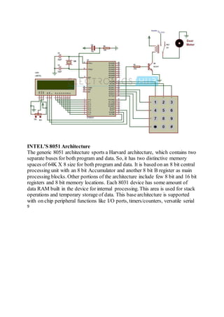
- 1. Password Based Door Lock System using 8051 Microcontroller Traditional lock systems using mechanical lock and key mechanism are being replaced by new advanced techniques of locking system. These techniques are an integration of mechanical and electronic devices and highly intelligent. One of the prominent features of these innovative lock systems is their simplicity and high efficiency. Such an automatic lock system consists of electronic control assembly which controls the output load through a password. This output load can be a motor or a lamp or any other mechanical/electrical load. Here we develop an electronic code lock system using 8051 microcontroller, which provides control to the actuating the load. It is a simple embedded system with input from the keyboard and the output being actuated accordingly. This system demonstrates a password based door lock system wherein once the correct code or password is entered, the door is opened and the concerned person is allowed access to the secured area. Again if another person arrives it will ask to enter the password. If the password is wrong then door would remain closed, denying the access to the person. Principle Behind the Circuit: The main component in the circuit is 8051 controller. In this project 4×3 keypad is used to enter the password. The password which is entered is compared with the predefined password. If the entered password is correct then the system opens the door by rotating door motor and displays the status of door on LCD. If the password is wrong then door is remain closed and displays “pwd is wrong” on LCD. Circuit Diagram of Password Based Door Lock System using 8051 Microcontroller:
- 2. Password Based Door Locking System Project Required Components: Hardware Requirements: at89c51 controller 8051 programming board Programming cable DC battery or 12V,1A adaptor 4×3 matrix keypad 16×2 LCD 5V Relay DC motor BC 547 Transistor 10k, 330 Ω resistor (1/4 watt) 10uF electrolytic capacitor 33pF capacitors – 2 12MHz Crystal
- 3. Pot 10k (1/4 watt) – 1 connecting wires Software Requirements: Keil compiler Flash magic Proteus Electronic Code Lock System Circuit Design: Password based door lock circuit design uses five major components – a Microcontroller, a Relay, a DC motor, a 4×3 matrix keypad and a LCD. Here AT89C51 microcontroller is used and it is an 8-bit controller. This controller requires a supply voltage of +5V DC. In order to provide regulated 5V DC voltage to the controller we need to use 7805 power supply circuit. We can use 9V DC battery or 12V, 1A adaptor as a power source. Reset Circuit Design: The reset pin of the microcontroller is kept active till the power supply is in the specified range and a minimum oscillation level is maintained. In other words to ensure the supply voltage does not falls below the threshold level of 1.2V and the reset pulse width is greater than 100ms (recommended for 89C51), we select the values of resistor and capacitor such that RC >=100ms. Here we select a 10K resistor and a 10uF electrolyte capacitor. Oscillator Circuit Design: A crystal oscillator is used to provide external clock signal to the microcontroller. To ensure smooth operation, we connect two ceramic capacitors ranges from 20pF to 40pF. This crystal oscillator is connected between pin 18 and 19 of the microcontroller. Compilation of Microcontroller Code: Once the circuit is designed and drawn on a piece of paper, the next step is to write and compile the code. Here we select the Kiel uVision software to write the program in C language. Prior to writing the code, general steps needs to be followed like creating a new project and selecting the target device or the required microcontroller. Once the code is written, we saved it with .c extension and then added it to the source file group under the target folder. The code is then compiled by pressing F7 key. Once the code is compiled, a hex file is created. In the next step, we use Proteus software to draw the circuit. The code is dumped into the microcontroller by right clicking on the IC and then adding the hex file.
- 4. FINAL REPORT Password Based Door Lock System using 8051 Microcontroller Submitted by CHINARAJA BARATAM 13BEC0728 SAMMER 13BEC0475 RAKESH 12BEC0419
- 5. ABSTRACT Security is a prime concernin our day-today life. Everyone wants to be as much secure as possible. An accesscontrolfor doors forms a vital link in a security chain. The microcontrollerbasedDoorlocker is an accesscontrol system that allows only authorized persons to accessa restricted area. The system is fully controlledby the 8 bit microcontrollerAT89C2051which has a 2Kbytes of ROM for the program memory. The passwordis storedin the EPROM so that we can change it at any time. The system has a Keypad by which the passwordcanbe entered through it. When they entered passwordequals with the passwordstoredin the memory then the relay gets on and so that the door is opened. If we entered a wrong passwordfor more than three times then the Alarm is switchedon. When we go inside and come back then the microcontrollerwill sense the person using the Laserlight, the microcontrollerwill automatically open the door for you. LIST OF TABLES: 1. PIN DESCRIPTION OF AT89C2051 2. PORT ALTERNATE FUNCTIONS LIST OF FIGURES: A. BLOCK DIAGRAM B. PIN OUT OF AT89C2051 C. BLOCK DIAGRAM OF AT89C2051 D. PCB FBRICATION E. FLOW CHART F. PINOUT FOR IC LM7805 G. BLOCK DIAGRAM OF IC LM7805 H. PINOUT FOR BC547
- 6. 1. INTRODUCTION “Password Based Door Security System using Microcontroller” is used in the places where we need more security. It can also used to secure lockers and other protective doors. The system comprises a number keypad and the keypads are connected to the 8 bit microcontroller AT89C2051. This is one of the popular Microcontrollers. It has only 20 pins and there are 15 input/output lines. The microcontroller has a program memory of 2Kilobytes. The microcontroller continuously monitor the keypad and if somebodyenters the password it will check the entered password with the password which was stored in the memory and if it they are same then the microcontroller will switch on the corresponding device. The systemwill allow the person who knows the passwordand it will not allow who don‟t know the passwordand the system will also show the persons who try to break the protection barrier. 2.1 BLOCK DIAGRAM
- 7. INTEL’S 8051 Architecture The generic 8051 architecture sports a Harvard architecture, which contains two separate buses for both program and data. So, it has two distinctive memory spaces of 64K X 8 size for both program and data. It is based on an 8 bit central processing unit with an 8 bit Accumulator and another 8 bit B register as main processing blocks. Other portions of the architecture include few 8 bit and 16 bit registers and 8 bit memory locations. Each 8031 device has some amount of data RAM built in the device for internal processing. This area is used for stack operations and temporary storage of data. This base architecture is supported with on chip peripheral functions like I/O ports, timers/counters, versatile serial 9
- 8. communication port. So it is clear that this 8051 architecture was designed to cater many real time embedded needs. The following list gives the features of the 8051 architecture: pace. Timers/Counters 8031 has two 16 bit Timers/Counters capable of working in different modes. Each consists of a `High' byte and a `Low' byte which can be accessed under software. There is a mode control register and a controlregister to configure these timers/counters in number of ways. These timers can be used to measure time intervals, determine pulse widths or initiate events with one microsecond resolution up to a maximum of 65 millisecond (correspondingto 65, 536 counts). Use software to get longer delays. Working as counter, they can accumulate occurrences of external events (from DC to 500 KHz) with 16 bit precision. In our project we are using 8 bit microcontroller AT89C2051, it is the advanced 8 bit microcontroller from ATMEL, which incorporates Flash Rom, and Timer etc. Features of AT89C2051: -51 Products -Level Program Memory Lock -Bit Internal RAM -Bit Timer/Counters 12
- 9. -Chip Analog Comparator 5. ALGORITM 1. START 2. initialise lcd , keypad 3. clear lcd 4. print “Enter lock code”on lcd 5. get 5 char long password using matrix key pad 6. if input = “12345” then 6.1 print “Enter master code” 6.2 get 10 char long password using matrix key pad 6.3 if input = masterlock then 6.3.1 change user password 6.3.2 go to step 4 6.4 else 6.4.1 print “ wrong code” on lcd 6.4.2 go to step 4 7. else 7.1 if input = userlock or input = default lock then 7.1.1 unlock the lock 7.1.2 retry count = 3 7.1.3 print “ „ #‟ to lock ” on lcd 7.1.4 acceptinput using matrix key pad 7.1.5 if input = “ # ” then lock 7.1.6 goto step 4 7.2 else 7.2.1 decrement retry count 7.2.2 print “ wrong code” on lcd 7.2.3 if retry count = 0 then sound alarm on 7.2.4 go to step 4 8. STOP
- 10. PROGRAM Delay program: #include "delay.h" void delayus(unsigned char delay) { while(delay--); } void delayms(unsigned char delay) { while(delay--) delayus(149); } Keypad program: #include "keypad.h" #include "delay.h" bit keystatus = FALSE; void keypad_init() { keyport &=0x0F; } unsigned char getkey () { unsigned char i,j,k,key=0,temp; k=1; for(i=0;i<4;i++) { keyport &=~(0x80>>i); temp = keyport; temp &= 0x07; if(7-temp) { if(!col1) { key = k+0; while(!col1); return key; } if(!col2) { key = k+1; 24
- 11. while(!col2); return key; } if(!col3) { key = k+2; while(!col3); return key; } j++; } k+=3; keyport |= 0x80>>i; delayms(10); } return FALSE; } unsigned char translate(unsigned char keyval) { if(keyval<10) return keyval+' else if(keyval==10) return 'x'; else if(keyval==11) return '0'; else if(keyval==12) return 'e'; } LCD program: #include "lcd.h" #include "delay.h" #include <REG2051.H> unsigned char codelockicon[]={0xe, 0xa, 0x1f, 0x1f, 0x1b, 0x1b, 0xe, 0x0}; unsigned char codeunlockicon[]={0xe, 0x2, 0x1f, 0x1f, 0x1b, 0x1b, 0xe, 0x0}; unsigned char codeex[]={0x1f, 0x1b, 0x1b, 0x1b, 0x1b, 0x1f, 0x1b, 0x1f}; unsigned char codeok[]={0x0, 0x1, 0x3, 0x16, 0x1c, 0x8, 0x0, 0x0}; void lcd_reset() { lcd_port= 0xFF; delayms(20); lcd_port= 0x03+LCD_EN; lcd_port = 0x03;
- 12. delayms(10); lcd_port= 0x03+LCD_EN; lcd_port= 0x03; delayms(1); lcd_port= 0x03+LCD_EN; lcd_port= 0x03; delayms(1); lcd_port= 0x02+LCD_EN; lcd_port= 0x02; delayms(1); } void lcd_init () { unsigned char i; lcd_reset(); lcd_cmd(LCD_SETFUNCTION);// 4-bit mode - 1 line - 5x7 font. lcd_cmd(LCD_SETVISIBLE+0x04); // Display no cursor - no blink. lcd_cmd(LCD_SETMODE+0x02); // Automatic Increment - No Display shift. lcd_cmd(LCD_SETCGADDR); for(i=0;i<8;i++) lcd_data(lockicon[i]); 27
- 13. for(i=0;i<8;i++) lcd_data(unlockicon[i]); for(i=0;i<8;i++) lcd_data(ex[i]); for(i=0;i<8;i++) lcd_data(for(i=0;i<8;i++) lcd_data(unlockicon[i]); for(i=0;i<8;i++) lcd_data(ex[i]); for(i=0;i<8;i++) lcd_data(ok[i]); lcd_cmd(LCD_SETDDADDR); // Address DDRAM with 0 offset 80h. } void lcd_cmd (char cmd) { lcd_port= ((cmd >> 4) & 0x0F)|LCD_EN; lcd_port= ((cmd >> 4) & 0x0F); lcd_port= (cmd & 0x0F)|LCD_EN; lcd_port= (cmd & 0x0F); delayus(200); delayus(200); } void lcd_data (unsigned char dat) { lcd_port= (((dat >> 4) & 0x0F)|LCD_EN|LCD_RS); lcd_port= (((dat >> 4) & 0x0F)|LCD_RS); lcd_port= ((dat & 0x0F)|LCD_EN|LCD_RS); lcd_port= ((dat & 0x0F)|LCD_RS); delayus(200); delayus(200); } void lcd_str(unsigned char *str) { while(*str){ lcd_data(*str++); } } Lock program: #include "keypad.h" #include "lcd.h" #include "delay.h" #include "lock.h" unsigned char codemasterlock[10]="1234567890", defaultulock[5]="54321"; unsigned char userlock[5], input[10]; extern bit newlock; bit check(unsigned char *first, unsigned char *second, unsigned char len)
- 14. { unsigned char i=0; lcd_str("Enter new code"); lcd_cmd(0xC0); lcd_data(LOCK); lcd_data(':'); status = getinput(5); if(status == TRUE){ lcd_cmd(LCD_CLS); lcd_data(OK); lcd_str("lockcodesaved!"); newlock = TRUE; store_code(); delayms(250); delayms(250); delayms(250); delayms(250); goto exit; } else if(status == RETRY) goto retry1; else if(status == EXIT goto exit; } else{ lcd_cmd(LCD_CLS); lcd_str("WRONG CODE!"); delayms(250); delayms(250); delayms(250); delayms(250); goto exit; } } else if(status == RETRY) goto retry; else if(status == EXIT) goto exit; exit:; } char getinput(unsigned char max) { unsigned char i,key; i=0;
- 15. while(1){ while(!(key=getkey())); key = translate(key); input[i]=key; if(key=='x'){ if(i==0) return EXIT; i--; lcd_cmd(0xC2+i); lcd_data(' '); lcd_cmd(0xC2+i); } else if(key=='e') { return TRUE; } else{ i++; if(i>max){ lcd_cmd(LCD_CLS); lcd_data(EX); lcd_str(" Codetoo Long..."); delayms(250); delayms(250); delayms(250); delayms(250); return RETRY; } lcd_data('*'); } } } void store_code(){ unsigned char i; for(i=0;i<5;i++) userlock[i]=input[i]; } Main program: #include "lcd.h" #include "keypad.h" #include "lock.h" #include "delay.h"extern unsigned char input[10], userlock[5]; extern unsigned char codedefaultulock[5],masterlock[10]; bit newlock=FALSE; unsigned char retrycount=3; void main(){ unsigned char status,i=0;
- 16. bit lockstatus; lcd_init(); keypad_init(); while(1){ lcd_cmd(LCD_CLS); lcd_str("Enter lock code"); lcd_cmd(0xC0); lcd_data(LOCK); lcd_data(':'); status = getinput(5); if(check(input,"12345",5)){ setulock();if(check(input,masterlock,10)){ retrycount=3; lcd_cmd(LCD_CLS); lcd_data(EX); lcd_str("UNBLOCKED"); lcd_data(EX); delayms(250); delayms(250); delayms(250); delayms(250); } else{ lcd_cmd(LCD_CLS); lcd_data(EX); lcd_str("WRONG CODE"); lcd_data(EX); delayms(250); delayms(250); delayms(250); delayms(goto blocked; } } } } done:; } }
- 17. Resistor: Resistor is a component that resists the flow of direct or alternating electric circuit. Resistors can limit or divide the current, reduce the voltage, protect an electric circuit, or provide large amounts of heat or light. An electric current is the movement of charged particles called electrons from one region to another. Resistors are usually placed in electric circuits. Physicists explain the flow of current through a material, such as a resistor, by comparing it to water flowing through a pipe. Resistors are designed to have a specific value of resistance. Resistors used in electric circuits are cylindrical. They are often colour coded by three or four colour bands that indicate the specific value of resistance. Resistors obey ohm‟s law, which states that the current density is directly proportional to the electric field when the temperature is constant. 7.2 Capacitor: Capacitor or electric condenseris a device for storing an electric charge. The simplest form of capacitor consists of two metal plates separated by a non touching layer called the dielectric. When one plate is charged with electricity from a direct current or electrostatic source, the other plate have induced in it a charge of the oppositesign; that is, positive if the original charge is negative and negative if the original charge ispositive. The electrical size of the capacitor is its capacitance. Capacitors are limited in the amount of electric charge they can absorb;they can conductdirect current for only instances but function well as conductors in alternating current circuits. Fixed capacity and variable capacity capacitors are used in conjunction with coils as resonant circuits in radios and other electronic equipment. Capacitors are produced in a wide variety of forms. Air, Mica, Ceramics, Paper, Oil, and Vacuums are used as dielectrics depending on the purposefor which the device is intended. 7.3 Transistor: Transistor is a device which transforms current flow from low resistance path to high resistance path. It is capable of performing many functions of the vacuum tube in electronic circuits, the transistor is the solid state device consisting of a tiny piece of semi conducting material, usually germanium or silicon, to which three or more electrical connections are made. N-type and P-type Transistor: A germanium or silicon crystal, containing donorimpurity atoms is called a negative or n-type semiconductorto indicate the presence of excess negatively charged electrons. The use of an acceptorimpurity produces a positive, or p- type semiconductorso called because of the presence of positively charged holes. When an electrical voltage is applied, the n-p junction acts as a rectifier, permitting current to flow in only onedirection. If the p-type region is connected to the positive terminal of the battery and the n-type to the negative terminal, a large current flows through the material across the junction.
- 18. 7.4 Diode: Diode is a electronic device that allows the passageof current in only one direction. The first such devices were vacuum-tube diodes, consisting of an evacuated glass or steel envelope containing two electrodes – a cathode and an anode. The diodes commonly used in electronic circuits are semiconductor diodes. There are different diodes used in electronic circuits such as Junction diode, Zener diode, Photo diodes, and tunnel diode. Junction diodes consist of junction of two different kinds of semiconductor material. The Zener diode is a special junction type diode, using silicon, in which the voltage across the junction is independent of the current through the junction. 7.5 Integrated circuits RegulatorIC (LM 7805): The LM7805 monolithic 3-terminal positive voltage regulators employ internal current-limiting, thermal shutdown and safe-area compensation, making them essentiallyindestructible. If adequate heat sinking is provided, they can deliver over 1.0A outputcurrent. They are intended as fixed voltage regulators in a wide range of applications including local(on- card) regulation for elimination of noise and distribution problems associatedwith single-point regulation. In addition to use as fixed voltage regulators, these devices canbe used with external components to obtain adjustable output voltages and currents. Considerable effort was expended to make the entire series of regulators easyto use and minimize the number of external components. It is not necessaryto bypass the output, although this does improve transient response. Input bypassing is needed only if the regulatoris locatedfar from the filter capacitorof the powersupply. thermal - Output transistorsafe area protection
- 19. RelayDriver (BC547): The BC547 transistor is an NPN Epitaxial Silicon Transistor. The BC547 transistor is a general-purpose transistor in small plastic packages. It is used in general-purpose switching and amplification BC847/BC547 series 45 V, 100 mA NPN general-purpose transistors. The BC547 transistor is an NPN bipolar transistor, in which the letters "N" and "P" refer to the majority charge carriers inside the different regions of the transistor. Most bipolar transistors used today are NPN, because electron mobility is higher than whole mobility in semiconductors, allowing greater currents and faster operation. NPN transistors consistof a layer of P- dopedsemiconductor(the "base")between two N-doped layers. A small current entering the base in common-emitter mode is amplified in the collector output. In other terms, an NPN transistor is "on" when its base is pulled high relative to the emitter. The arrow in the NPN transistor symbolis on the emitter leg and points in the direction of the conventional current flow when the device is in forward active mode. One mnemonic device for identifying the symbol for the NPN transistor is "not pointing in." An NPN transistor can be considered as two diodes with a shared anode region. In typical operation, the emitter base junction is forward biased and the base collector junction is reverse biased. In an NPN transistor, for example, when a positive oltage is applied to the base emitter junction, the equilibrium between thermally generated carriers and the repelling electric field of the depletion region becomes unbalanced, allowing thermally excited electrons to inject into the base region. These electrons wander (or "diffuse") through the base from the region of high concentration near the emitter towards the region of low concentration near the collector. The electrons in the base are called minority carriers because the base is doped p- type which would make holes the majority carrier in the base *PCB FABRICATION The first step of assembling is to produce a printed circuit board. The fabrication of the programcounter plays a crucial role in the electronic field. The success of the circuit is also dependent on the PCB. As far as the costis concerned, more than 25% of the total costis for the PCB design and fabrication. The board is designed using a personalcomputer. The layout is drawn using the software“AdobePageMaker 6.5”. The layoutis printed in a “buffer sheet” using a laser procedure. First, a negative screen of the layout is prepared with the help of a professionalscreen printer. Then the copper clad sheet is kept under this screen. The screen printing ink is poured on the screen and brushed
- 20. through the top of the screen. The printed board is kept under shadefor few hours till the ink becomes dry. The etching medium is prepared with the un-hydrous ferric chloridewater. The printed board is kept in this solution till the exposed copper dissolves in the solution fully. After that the board is taken out and rinsed in flowing water under a tap. The ink is removed with solder in order to prevent oxidation. Another screen, whichcontains component side layout, is preparedandthe same is printedonthe component side of the board. A paper epoxy laminate is usedas the board. Boththe component and the track layout of the peripheral PCB is givenat the end of this report. APPLICATIONS Our electronic doorlock performed as expected. We were able to implement all the functions specifiedin our proposal. The biggesthurdle we had to overcome with this projectwas interfacing the micro controller with the hardware components. We feel that this electronic doorlock is very marketable because it is easyto use, comparatively inexpensive due to low powerconsumption, and highly reliable. This door lock is therefore particularly useful in applications such as hotel room door locks, residential housing, and even office buildings. 10. FUTURE ENHANCEMENTS separate passwords. e system can be easily connected to the personal computer for further control. Other than the speaker sounds, all the lights are made to turned on if password entered is wrong for three times and also a hidden camera is used to record the faces who trespassed. We can use this system as an attendance register for the students to enter a class room with their respective password. 11. CONCLUSION This project is meant for security systems whose access is only for respected authorities. Using a microcontroller the password entered is checked with the stored password and then does the corresponding operations. Here we use a 5 digit password for better secrecy.
- 21. 12. REFERENCES Electronic circuits and devices: J.B. Gupta. Op-amps and linear integrated circuits: Ramakanth A. Gayakward Integrated circuits : K.R. Botkar The 8051 microcontrollers: Muhammed Ali Mazidi